WO2012153629A1 - Dispositif et procédé pour contrôler la prédiction du mouvement - Google Patents
Dispositif et procédé pour contrôler la prédiction du mouvement Download PDFInfo
- Publication number
- WO2012153629A1 WO2012153629A1 PCT/JP2012/060918 JP2012060918W WO2012153629A1 WO 2012153629 A1 WO2012153629 A1 WO 2012153629A1 JP 2012060918 W JP2012060918 W JP 2012060918W WO 2012153629 A1 WO2012153629 A1 WO 2012153629A1
- Authority
- WO
- WIPO (PCT)
- Prior art keywords
- robot
- internal state
- control
- data storage
- state
- Prior art date
Links
Images


Classifications
-
- B—PERFORMING OPERATIONS; TRANSPORTING
- B25—HAND TOOLS; PORTABLE POWER-DRIVEN TOOLS; MANIPULATORS
- B25J—MANIPULATORS; CHAMBERS PROVIDED WITH MANIPULATION DEVICES
- B25J13/00—Controls for manipulators
- B25J13/08—Controls for manipulators by means of sensing devices, e.g. viewing or touching devices
-
- B—PERFORMING OPERATIONS; TRANSPORTING
- B25—HAND TOOLS; PORTABLE POWER-DRIVEN TOOLS; MANIPULATORS
- B25J—MANIPULATORS; CHAMBERS PROVIDED WITH MANIPULATION DEVICES
- B25J19/00—Accessories fitted to manipulators, e.g. for monitoring, for viewing; Safety devices combined with or specially adapted for use in connection with manipulators
- B25J19/02—Sensing devices
- B25J19/021—Optical sensing devices
- B25J19/023—Optical sensing devices including video camera means
-
- B—PERFORMING OPERATIONS; TRANSPORTING
- B25—HAND TOOLS; PORTABLE POWER-DRIVEN TOOLS; MANIPULATORS
- B25J—MANIPULATORS; CHAMBERS PROVIDED WITH MANIPULATION DEVICES
- B25J5/00—Manipulators mounted on wheels or on carriages
- B25J5/007—Manipulators mounted on wheels or on carriages mounted on wheels
-
- B—PERFORMING OPERATIONS; TRANSPORTING
- B25—HAND TOOLS; PORTABLE POWER-DRIVEN TOOLS; MANIPULATORS
- B25J—MANIPULATORS; CHAMBERS PROVIDED WITH MANIPULATION DEVICES
- B25J9/00—Programme-controlled manipulators
- B25J9/16—Programme controls
- B25J9/1656—Programme controls characterised by programming, planning systems for manipulators
- B25J9/1664—Programme controls characterised by programming, planning systems for manipulators characterised by motion, path, trajectory planning
-
- B—PERFORMING OPERATIONS; TRANSPORTING
- B25—HAND TOOLS; PORTABLE POWER-DRIVEN TOOLS; MANIPULATORS
- B25J—MANIPULATORS; CHAMBERS PROVIDED WITH MANIPULATION DEVICES
- B25J9/00—Programme-controlled manipulators
- B25J9/16—Programme controls
- B25J9/1694—Programme controls characterised by use of sensors other than normal servo-feedback from position, speed or acceleration sensors, perception control, multi-sensor controlled systems, sensor fusion
- B25J9/1697—Vision controlled systems
-
- G—PHYSICS
- G05—CONTROLLING; REGULATING
- G05B—CONTROL OR REGULATING SYSTEMS IN GENERAL; FUNCTIONAL ELEMENTS OF SUCH SYSTEMS; MONITORING OR TESTING ARRANGEMENTS FOR SUCH SYSTEMS OR ELEMENTS
- G05B2219/00—Program-control systems
- G05B2219/30—Nc systems
- G05B2219/32—Operator till task planning
- G05B2219/32357—Simulation of material handling, flexible conveyor system fcs
-
- G—PHYSICS
- G05—CONTROLLING; REGULATING
- G05B—CONTROL OR REGULATING SYSTEMS IN GENERAL; FUNCTIONAL ELEMENTS OF SUCH SYSTEMS; MONITORING OR TESTING ARRANGEMENTS FOR SUCH SYSTEMS OR ELEMENTS
- G05B2219/00—Program-control systems
- G05B2219/30—Nc systems
- G05B2219/37—Measurements
- G05B2219/37436—Prediction of displacement, relative or absolute, motion
-
- G—PHYSICS
- G05—CONTROLLING; REGULATING
- G05B—CONTROL OR REGULATING SYSTEMS IN GENERAL; FUNCTIONAL ELEMENTS OF SUCH SYSTEMS; MONITORING OR TESTING ARRANGEMENTS FOR SUCH SYSTEMS OR ELEMENTS
- G05B2219/00—Program-control systems
- G05B2219/30—Nc systems
- G05B2219/40—Robotics, robotics mapping to robotics vision
- G05B2219/40512—Real time path planning, trajectory generation
-
- G—PHYSICS
- G05—CONTROLLING; REGULATING
- G05B—CONTROL OR REGULATING SYSTEMS IN GENERAL; FUNCTIONAL ELEMENTS OF SUCH SYSTEMS; MONITORING OR TESTING ARRANGEMENTS FOR SUCH SYSTEMS OR ELEMENTS
- G05B2219/00—Program-control systems
- G05B2219/30—Nc systems
- G05B2219/41—Servomotor, servo controller till figures
- G05B2219/41146—Kalman filter
-
- G—PHYSICS
- G05—CONTROLLING; REGULATING
- G05B—CONTROL OR REGULATING SYSTEMS IN GENERAL; FUNCTIONAL ELEMENTS OF SUCH SYSTEMS; MONITORING OR TESTING ARRANGEMENTS FOR SUCH SYSTEMS OR ELEMENTS
- G05B2219/00—Program-control systems
- G05B2219/30—Nc systems
- G05B2219/42—Servomotor, servo controller kind till VSS
- G05B2219/42263—Different sample rates, multiple sample rates for the different loops
-
- Y—GENERAL TAGGING OF NEW TECHNOLOGICAL DEVELOPMENTS; GENERAL TAGGING OF CROSS-SECTIONAL TECHNOLOGIES SPANNING OVER SEVERAL SECTIONS OF THE IPC; TECHNICAL SUBJECTS COVERED BY FORMER USPC CROSS-REFERENCE ART COLLECTIONS [XRACs] AND DIGESTS
- Y02—TECHNOLOGIES OR APPLICATIONS FOR MITIGATION OR ADAPTATION AGAINST CLIMATE CHANGE
- Y02P—CLIMATE CHANGE MITIGATION TECHNOLOGIES IN THE PRODUCTION OR PROCESSING OF GOODS
- Y02P90/00—Enabling technologies with a potential contribution to greenhouse gas [GHG] emissions mitigation
- Y02P90/02—Total factory control, e.g. smart factories, flexible manufacturing systems [FMS] or integrated manufacturing systems [IMS]
Definitions
- the present invention relates to a motion prediction control apparatus and method for predicting the motion of a workpiece, a robot, etc., among automatic devices using a robot or the like.
- Sensors and measurement methods used to measure the robot's position and orientation in a control device that calculates and controls the robot's position and orientation using sensor information installed on and outside the robot The following is common.
- a method using an internal sensor on the robot For example, the speed, acceleration, angular velocity, etc. of the robot are measured with a gyro sensor or wheel encoder installed on the robot.
- the steer angle of the robot is measured with the encoder of the steering unit installed on the robot.
- LRF laser range finder
- One or both of the current position and posture of the robot are measured with a GPS compass installed on the robot.
- a method of measuring with an external sensor outside the robot The position and orientation of the robot within the measurement range are measured with a distance measuring sensor or camera installed outside the robot.
- the position and orientation measured in (3) are a relative position and orientation represented by a sensor to be measured and a coordinate system based on a specific point.
- the base points of the measurement coordinates are different from one another, and in the case of a sensor on the robot, the position of the robot itself as the base point is unknown, so it is difficult to compare these measurement results simply by coordinate transformation or the like. Since (1) does not directly measure the position or orientation, it cannot be directly compared with (2) or (3).
- the measurement times of the obtained measurement results may be different. Since the position and posture of the robot change from moment to moment, it is not possible to simply compare measurement results that do not have the same time. In particular, when the robot speed is high, the amount of change in position and orientation is large, and such a problem is likely to occur.
- sensor information of internal sensors in the same robot is acquired synchronously.
- b When using an external sensor as in (3), it is difficult to synchronize the external sensor and the sensor on the robot when a synchronization signal needs to be exchanged between a plurality of devices, as in a.
- the sensors used in (2) and (3) have a measurement delay due to the measurement time of the sensor itself, the time to process sensor information obtained from the sensor, and the like.
- the measurement result obtained by the sensor becomes sensor information that is old due to the measurement delay, the sensor information of the internal sensor as in (1) is different from the measurement time. Further, since the measurement target may be out of the field of view of the sensor, the measurement result at the designated time is not always obtained.
- the position of the workpiece is measured by a visual sensor such as a camera installed on the robot or outside the robot, or a distance measuring sensor such as a laser range finder (LRF). Based on this, it is necessary to control the robot arm to follow up. Even in the case of a mobile robot in which the robot itself moves, it is necessary to measure the position of the mobile robot with a sensor installed on the robot or outside the robot and control the robot based on the measurement result, and the same technique is used.
- a visual sensor such as a camera installed on the robot or outside the robot
- LRF laser range finder
- the method for measuring the position of the robot includes a method for measuring the relative position to the landmark with a sensor on the robot and a method for directly measuring the position of the robot with a sensor installed outside the robot.
- the moving workpiece and the moving robot are also simply referred to as “moving body”.
- the object that changes from moment to moment and the relative position between the robots are measured at a constant period (eg, 30 fps camera), and based on the measurement result, for example, the workpiece A movement command is output to the robot to bring the robot closer to the robot.
- a constant period eg, 30 fps camera
- the robot may not be able to follow the workpiece that is moving due to control delays such as sensor measurement delay, data acquisition delay, and robot operation delay.
- control delays such as sensor measurement delay, data acquisition delay, and robot operation delay.
- the robot since the sensor measurement cycle is generally longer than the robot control cycle (eg, 4 ms), the robot cannot obtain the latest measurement results for each control cycle. Become.
- the image processing takes time or the work is out of the field of view of the camera, the measurement result update period becomes longer and is not constant.
- the tracking performance of the robot is deteriorated due to a control delay.
- Patent Documents 1 to 4 In order to solve the problems related to the background art described above, various control means have already been proposed (for example, Patent Documents 1 to 4).
- the “three-dimensional motion prediction device” of Patent Document 1 estimates a motion parameter from position data of an object that performs simple vibration, predicts its future position, and uses a manipulator to select the object based on the position information. To grip.
- the “state estimation means” in Patent Document 2 estimates the internal state of the system that performed the observation based on the observation signal input in time series by the observation.
- the internal state means state variables such as the position, posture, and deflection angle of the object.
- the “motion prediction device” of Patent Document 3 performs automatic tracking and motion prediction by using both background processing and foreground processing.
- Robot Device and Control Method Therefor” of Patent Document 4 first, the arm is made to follow the object, and the movement state of the arm at the time of following and the movement state of the object coincide with each other. A method for predicting the destination of the movement has been proposed. As described above, the moving object is grasped by predicting the movement destination of the object in consideration of the movement state of the arm.
- Patent Document 1 by estimating the motion state of the object from the observation history of measuring the object (measured object or workpiece), the data while the measured value is not obtained can be supplemented. It is possible to predict the gripping point when the object is gripped by the robot.
- a Bayesian filter such as a Kalman filter or a particle filter is generally used for estimating the motion state.
- the state of motion (speed, acceleration, etc. of the object) is set to “internal state”, and “state transition” indicating how the internal state changes with time.
- the “model” in advance and define the “observation equation”.
- the Bayes filter is roughly divided into the following two processes.
- Prediction process for predicting an internal state at an arbitrary time.
- Update process in which a measurement value is predicted from an internal state and compared with an actual measurement value to correct the internal state (described in Patent Document 2 as “filter estimation means”).
- the update process of the state estimator generally takes time, especially when there are many types of measurement values, and particularly when using a particle filter or other complicated processes.
- the means of Patent Document 2 can reduce the amount of calculation according to the purpose by dividing the prediction process and the update process according to the types of observation values and state variables. When all values are to be reflected, all processes need to be connected after all, so the amount of calculation required for estimation does not decrease.
- the robot controller does not need to perform the update process, but after the robot requests the predicted value, the estimation apparatus must complete the prediction process within a certain time and return the predicted value. I must.
- the following problems need to be considered.
- an object of the present invention is to estimate the internal state of one or both of the object and the robot, and generate a predicted value (control command value) necessary for controlling the robot based on this internal state.
- An object of the present invention is to provide a motion prediction control apparatus and method capable of generating a control command value in a predetermined control cycle without being affected by the time required for state update processing.
- a measuring device that acquires sensor information by measuring one or both of an object and a robot; A state estimation device that predicts and updates the internal state of one or both of the object and the robot based on the sensor information; A data storage device for storing the internal state; A robot control device for controlling the robot, The state estimation device updates the internal state at an arbitrary timing independent of the robot control cycle, The robot control device is provided with a motion prediction control device that calculates a prediction value necessary for controlling the robot based on the latest internal state stored in the data storage device in the control cycle.
- the measuring device measures the relative relationship between the object and the robot as the sensor information
- the state estimation device is used for the object and the robot (one or both of the object and the robot).
- Predict and update internal state
- the state estimation device includes an overall prediction unit that predicts the internal state, and an update unit that updates the internal state stored in the data storage device
- the robot control device has an on-robot prediction unit that predicts a prediction value necessary for the control in the control period of the robot, (A) At an arbitrary timing that does not depend on the control cycle, the measurement device, the state estimation device, and the data storage device measure the relative relationship between the object and the robot and predict the internal state of the object and the robot.
- the robot control device predicts the predicted value in the control cycle based on the latest internal state stored in the data storage device, and controls the robot in real time based on the predicted value.
- the relative relationship between the target object and the robot is a relative relationship between the target object and the robot controlled by the robot control device (for example, relative position, relative posture, relative speed, relative acceleration, or relative posture change), or It means a relative relationship (for example, relative position, relative posture, relative speed, relative acceleration, or relative posture change) between a robot controlled by the robot control device and another robot (the same applies hereinafter).
- the measuring device can be used for an object and a plurality of robots (that is, the object and the plurality of robots, the object, the plurality of robots, or , Part of multiple robots) sensor information
- the state estimation device acquires the sensor information
- the state estimation device predicts the internal state of each robot at the same time as the time when the sensor information is acquired, and converts the predicted internal state (for example, into sensor information using an observation equation).
- Update compared to the measured sensor information
- the data storage device stores the updated internal state and the state transition equation used for the prediction
- the plurality of robot control devices predict a predicted value required for each robot based on the latest internal state stored in the data storage device.
- the robot grips a relatively moving object
- the measuring device measures the position or orientation of the object as the sensor information
- the state estimation device updates the internal state of the object including the accuracy index value based on the state transition model and the observation model from the measurement result obtained by measuring the object, and determines whether the object can be gripped from the accuracy index value.
- the robot control device controls the robot to perform a gripping operation by predicting the destination of the target based on the update result of the internal state.
- (A) sensor information is acquired by measuring one or both of the object and the robot with a measuring device, (B) Based on the sensor information, the state estimation device predicts and updates the internal state of one or both of the object and the robot, (C) storing the internal state by a data storage device; (D) controlling the robot with a robot controller; In (B), the state estimation device updates the internal state at an arbitrary timing that does not depend on the robot control cycle, In (D), the robot controller calculates a predicted value necessary for controlling the robot based on the latest internal state stored in the data storage device in the control cycle.
- a control method is provided.
- the state estimation device includes an overall prediction unit that predicts the internal state, and an update unit that updates the internal state stored in the data storage device,
- the relative relationship between the object and the robot is measured as the sensor information by the measurement device, the state estimation device, and the data storage device at an arbitrary timing that does not depend on the control cycle.
- Predict and update the internal state of the object or robot store the updated internal state and the state transition equation used for the prediction,
- the robot control device predicts the predicted value in the control cycle, and controls the robot in real time.
- the sensor device acquires sensor information of the object and the plurality of robots in (A).
- the internal state of each robot at the same time as the time when the sensor information is acquired by the state estimation device is predicted, and the predicted internal state is updated by comparing with the sensor information.
- the update is performed by the data storage device.
- a plurality of robot control devices predict predicted values required for each robot based on the latest internal state stored in the data storage device.
- the robot grips a relatively moving object, In (A), the measurement device measures the position or orientation of the object as the sensor information, In (B), the state estimation device updates the internal state of the object including the accuracy index value based on the state transition model and the observation model, and grasps the object from the accuracy index value. Determine whether or not In (D), when the gripping is possible, the robot controller predicts the movement destination of the object based on the update result of the internal state, and causes the robot to perform a gripping operation. If gripping is not possible, repeat steps (A) and (B) until gripping is possible.
- sensor information of one or both of the object and the robot is acquired at an arbitrary timing that does not depend on the control cycle of the robot, and the internal state of one or both of the object and the robot is based on the sensor information. Therefore, it is not necessary to update the internal state within the robot control cycle. Further, since the predicted value is predicted in the control cycle based on the latest internal state stored in the data storage device and the robot is controlled in real time, it is determined without being affected by the amount of calculation of state estimation. It is possible to control the robot by calculating a predicted value (control command value) necessary for controlling the robot in the control cycle. Therefore, the robot controller can generate a control command value at a determined control cycle without being affected by the time required for the internal state update process.
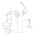
- FIG. 1 is a first configuration example of a robot system including a motion prediction control apparatus according to a first embodiment of the present invention.
- 1 is a workpiece
- 2 is a movable robot
- 3 is a robot arm
- 4 is a hand
- 5a is a first camera fixed to the hand 4
- 5b is a second camera fixed to an external fixed position
- 6 is a fixed landmark
- 10 is a motion prediction control apparatus of the first embodiment.
- the workpiece 1 and the landmark 6 are collectively referred to as an “object”.
- This robot system measures the workpiece 1 moving while pendulum movement and the fixed landmark 6 with the cameras 5a and 5b, measures the robot 2 with the camera 5b, and controls the robot 2 to follow the workpiece 1,
- the workpiece 1 is held by the hand 4.
- the position of the landmark 6 need not be known.
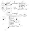
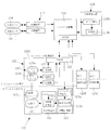
- FIG. 2 is a first configuration example of the motion prediction control apparatus according to the first embodiment of the present invention.
- the motion prediction control device 10 of the first embodiment includes a measurement device 12, a state estimation device 14, a data storage device 16, and a robot control device 20.
- the devices 12, 14 and 20 are connected to the data storage device 16.
- the measuring device 12 measures the relative relationship between the object and the robot 2.
- a measurement result Y such as the relative position or posture between the object and the robot measured by the measurement device 12 is defined as a measurement value Y.
- the measurement value Y is defined according to the type of measurement device and the object to be measured.
- the measured value Y differs depending on the object to be measured (whether it is workpiece 1, landmark 6 or mobile robot 2) and the type of measuring device.
- the relative relationship is information such as position, posture, speed, angular velocity, acceleration, angular acceleration, and the like.
- the measurement device 12 includes three measurement devices (first measurement device 12a, second measurement device 12b, and third measurement device 12c) connected to the first camera 5a, the second camera 5b, and the robot control device 20, respectively. ). That is, in this example, two cameras and two measuring devices are used, the images of the object are taken from the first camera 5a and the second camera 5b, and the measurement value Y of the object is obtained by image processing.
- the measuring device 12b also captures the image of the robot 2 and obtains the measured value Y of the robot 2 by image processing.
- the measuring device 12c measures the amount of movement of the tire of the robot 2 and the amount of rotation of the arm joint with an encoder, and obtains the measured value Y of the robot 2.
- the obtained object and the measured value Y of the robot 2 are stored in the data storage device 16.
- the measuring device 12 is not limited to this configuration, and a device that can measure the relative relationship between the object and the robot 2, such as a laser radar, an acceleration sensor, a gyro sensor, or a speed sensor, may be used.
- the state estimation device 14 is implemented with a state estimation algorithm based on the Kalman filter algorithm.
- the swing angle ⁇ of the pendulum on which the workpiece 1 is suspended ⁇ , fulcrum positions x, y, and z, the positions Xl, Yl, and Zl of the landmark 6, the postures RXl, RYl, RZl, and the position of the robot 2
- State variables such as Xr, Yr, Zr, and postures RXr, RYr, RZr are collectively set as an internal state X.
- An observation equation is defined for each type of measurement value Y. This algorithm manages the error distribution C ov X of the internal state X, the error distribution C ov Y of the measurement value, and the like, and the accuracy of state estimation can be obtained from these data. In the following example, these accuracy index values are collectively referred to as E.
- the state estimation device 14 includes an overall prediction unit 15 a that predicts the internal state of the object and the robot 2, and an update unit 15 b that updates the internal state stored in the data storage device 16. Predict and update internal state.
- the overall prediction unit 15a performs a calculation for causing the internal state X recorded in the data storage device 16 to transition to a designated time using the state transition equation f (X).
- the update unit 15b calculates the predicted value of the measurement value Y of the object and the robot 2 using the internal state X in the data storage device 16 and the observation equation h (X).
- the input measurement value Y and the predicted value are compared, and the internal state X is updated and recorded in the data storage device 16.
- the state estimation accuracy index E is simultaneously updated and recorded in the data storage device 16.
- the measurement device 12, the state estimation device 14, and the data storage device 16 described above are non-real-time processing systems that are executed at a timing different from the control cycle of the robot 2.
- the processing interval of this non-real time processing system may be longer than the control cycle of the robot 2 and the cycle may not be constant. This processing interval is, for example, 30 to 80 ms. Therefore, with the above-described configuration, the measurement device 12, the state estimation device 14, and the data storage device 16 measure the relative relationship (for example, relative position and posture) between the object and the robot at a timing different from the control cycle of the robot 2. Then, the internal state of the object and the robot 2 is predicted and updated, and the updated internal state and the state transition equation used for the prediction are stored.
- the robot control device 20 includes a reception unit 21, a command value calculation unit 22, a transmission unit 23, and an on-robot prediction unit 24.
- the receiving unit 21 receives position information (such as encoder information) from the robot 2.
- the command value calculation unit 22 calculates a command value for the robot 2 from the prediction value obtained by the on-robot prediction unit 24.
- the predicted value is, for example, the current position or future position of the workpiece 1 or the robot 2.
- the transmission unit 23 transmits the calculated command value to the robot 2.
- the on-robot prediction unit 24 predicts a prediction value necessary for controlling the robot 2 at a predetermined control cycle.
- the robot control device 20 includes an on-robot prediction unit 24 that performs a prediction process (prediction) for obtaining a prediction value necessary for controlling the robot 2.
- the on-robot prediction unit 24 only needs to be able to predict the internal quantity (predicted value) related to the control of the robot 2, and does not need to predict all the internal quantities.
- the robot control device 20 transmits an operation command to the robot 2 at a constant cycle (for example, 4 ms) and receives encoder information of the robot 2 and the like.
- the received position information is acquired by the above-described measuring device 12 c and becomes the measurement value Y of the mobile robot 2.
- the on-robot prediction unit 24 is used to predict current and future motion states of the target object and the robot 2 and use them to calculate command values.
- the on-robot prediction unit 24 calculates the state quantity related to the robot control among the internal states X recorded in the data storage device 16 by using the state transition equation f (X) until the specified time. I do.
- the data storage device 16 holds data such as the internal state X, the internal model time tx, the measured value Y, the measured time ty, the state transition equation f, the observation equation h, and the state estimation accuracy index value E. To do.
- the robot control device 20 described above is a real-time processing system controlled by the control cycle of the robot 2.
- This control cycle is a fixed cycle shorter than the processing interval of the non-real time processing system described above.
- This control cycle is, for example, 3 to 4 ms. Therefore, with the above-described configuration, the robot control device 20 predicts a predicted value necessary for the control in the control cycle of the robot 2 based on the latest internal state stored in the data storage device 16, and makes the robot 2 in real time. To control.
- the measuring device 12 measures the object and the robot 2 at an arbitrary timing, and records the measurement result as sensor information in the data storage device 16.
- the state estimation device 14 estimates the internal state by a prediction process and an update process (Collection). The calculated internal state and the state transition equation used for estimation are recorded in the data storage device 16.
- the robot control device 20 controls the robot 2 at a constant control cycle. At this time, the predicted position of the object and the robot 2 at an arbitrary time is calculated using the on-robot prediction unit 24 and used for control.
- the on-robot prediction unit 24 performs a prediction process using the latest internal state or state transition model recorded in the data storage device 16.
- the robot controller 20 operates as a real-time processing system that performs processing at a constant control cycle. Each of the other devices may be a non-real-time processing system that does not have a fixed period time constraint.
- the two measuring devices repeat the following (1) to (3) at an arbitrary timing.
- a shutter signal is transmitted to the cameras 5a and 5b at an arbitrary timing, and a captured image is acquired.
- the position / posture information (measurement value Y) of the object and the robot 2 is acquired from the obtained image by image processing. For example, a white area in the image is extracted and the center of gravity is obtained.
- the calculated measurement value Y, the shutter time (measured value time ty), and the error distribution C ov Y of the measurement value Y are recorded in the data storage device 16.
- the measuring device 12c repeats the following (a1) to (a3) at an arbitrary timing.
- A1 Acquire encoder information of the robot controller 20 at an arbitrary timing.
- A2) The movement amount and joint angle of the tire are obtained from the obtained encoder information, and the position / posture information (measured value Y) of the mobile robot 2 is obtained.
- A3) The calculated measurement value Y, the measurement time of the encoder, and the error distribution C ov Y of the measurement value Y are recorded in the data storage device 16.
- the state estimation device 14 performs the following (4) to (6) every time the measurement value Y is updated.
- the data storage device 16 is monitored, and if a new measurement value Y is recorded, Y, ty, X, tx, f, h, E are read from the data storage device 16.
- the internal state X indicates the internal state at the time tx
- the internal state at the time ty is predicted using the overall prediction unit 15a.
- (6) Using the update unit 15b, the measured value at the time ty is predicted, the predicted value and the measured value Y are compared, and the internal state X is corrected.
- the update unit 15 b calculates an error distribution C ov X of the internal state X and an accuracy index E such as a difference between the measured value and the predicted value, and records it in the data storage device 16.
- the robot controller 20 repeats the following (7) to (10) at an arbitrary cycle.
- Communication with the robot 2 is managed by the robot 2 so as to be performed, for example, at a cycle of 4 ms. Therefore, the robot control unit 20 must wait until data is received, and complete the transmission process (11) within 4 ms after receiving the data.
- the current position of the workpiece and the robot and the future position are calculated using the robot prediction unit 24. When performing this calculation, the on-robot prediction unit 24 refers to the latest internal state or the like in the data storage device 16. (9) A target trajectory is calculated so that the arm hand approaches the predicted position of the workpiece 1.
- the arm target trajectory and the hand opening / closing command value are calculated so that the gripping operation is performed to the position of the future workpiece. . (10)
- the calculated target trajectory and hand opening / closing command value are transmitted to the robot 2.
- FIG. 3 is a second configuration example of the motion prediction control apparatus according to the first embodiment of the present invention. This example is suitable when the time required for communication between the robot control device 20 and the data storage device 16 is long. That is, in this example, the data storage device 16 has a function of transferring the latest internal state stored in the data storage device 16 to the robot storage unit 26 at a timing that does not depend on the request from the robot 2.
- the data storage device 16 transfers the internal state and state transition model recorded in the data storage device 16 to the on-robot storage unit 26.
- the on-robot prediction unit 24 performs processing with reference to data stored in the on-robot storage unit 26.
- the transfer timing may be when the internal state X of the data storage device 16 is updated (immediately after (6)). Data transfer is performed when it is detected that new data has been recorded in the data storage device 16 (immediately after (6)) or at regular intervals. Alternatively, it may be performed at both timings described above.
- the contents of the data storage device 16 are sequentially transferred to the on-robot storage unit 26, and the on-robot prediction unit 24 refers to the on-robot storage unit 26. Therefore, it is necessary to communicate in the calculation of (8) described above. There is no. Therefore, even when communication using a long communication time such as wireless communication is used, the influence of communication time can be avoided.
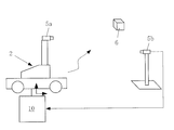
- FIG. 4 is a second configuration example of the robot system including the motion prediction control apparatus according to the first embodiment.
- This example is different from the first configuration example of the robot system in that the robot 2 is fixed and there is no landmark 6.
- Other configurations are the same as those of the first configuration example. That is, this example is a case in which the workpiece 1 moving with the arm 3 of the fixed robot 2 is gripped, and is different from the first configuration example of the robot system in that it is not necessary to estimate the robot 2.
- FIG. 5 is a third configuration example of the robot system including the motion prediction control device according to the first embodiment.
- This example is a case in which the robot 2 estimates its own position from the landmark 6 whose position is known, and the first configuration example is that it is not necessary to estimate the workpiece and the position and orientation of the landmark 6. And different.
- the mobile robot 2 measures the landmark 6 whose position is known, and estimates the self-position of the robot 2.
- the estimated internal quantity X is the origin position (X r , Y r , Z r ) of the robot 2 and the posture (R xr , R yr , R zr ) of the robot 2.
- the steer angle, speed, angular velocity, etc. of the wheel may be estimated.
- the wheel rotation amount ( ⁇ ) recorded by the robot controller 20 as a result of measuring the landmark 6 by the camera 5a, the position of the robot 2 by the camera 5b, or the like is used.
- the other points may be the same as those of the first configuration example of the robot system.
- the first embodiment of the present invention is not limited to the configuration example described above.
- it is a combination of workpiece motion state estimation and robot motion state estimation, so the first embodiment described above realizes a system that takes into account the time constraints of robot control. it can.
- the pendulum work and the wheel-type mobile robot are shown.
- the form in which each moves is not limited thereto.
- the workpiece may be one that moves on a conveyor, one that floats on water, or one that is flying.
- the robot may be a crawler type or a type that moves on a rail.
- “moving” includes cases in which the base sways or passively moves even with a fixed arm.
- each device need not be separated into separate processing devices.
- a configuration in which a plurality of programs are processed in parallel on one PC may be used as the measurement program and the state estimation program.
- the robot control device is a real-time processing system that performs processing under the constraint of a fixed period.
- a non-real-time processing program and a real-time processing program can be paralleled.
- the data storage device 16 may be a shared memory in which a plurality of devices and programs read and write the same data. Therefore, it is not necessary to use an independent device, and it is sufficient that the device is prepared in a memory space such as the state estimation device 14 or the measurement device 12.
- the measurement device 12, the state estimation device 14, and the data storage device 16 measure the relative relationship (for example, relative position) between the object and the robot, Predicts and updates the internal state between robots and stores the updated internal state and the state transition equation used for the prediction, so the measurement results (for example, position and orientation) of the object (work or landmark) and the robot ) To predict the motion of the moving body (work or mobile robot).
- the robot control device 20 has an on-robot prediction unit 24 that predicts a predicted value necessary for controlling the robot 2 in the control cycle of the robot 2, and the latest internal state stored in the data storage device 16 is updated. Based on this, the predicted value is predicted in the control cycle, and the robot 2 is controlled in real time. Therefore, the control command value is calculated in the control cycle determined for each robot without being affected by the calculation amount of the state estimation. The robot 2 can be controlled.
- the robot controller 20 can operate without being affected by the time required for the state estimation update process. Even when the number of measuring devices 12 and robot control devices 20 increases and the amount of calculation for state estimation increases, the time required for the prediction process does not increase because each robot control device 20 performs prediction calculation independently. Therefore, it is not necessary to review the design of arithmetic processing capacity when the system is changed. Furthermore, the time constraint of the prediction process can be set for each robot control device 20. Also, the accuracy of the predicted value to be calculated, the type of predicted value, and the like can be set for each robot control device 20. Therefore, in consideration of the time required for the prediction process, the control period, and the like, the respective robots 2 can realize contrivances such as changing the accuracy of the prediction calculation or calculating only necessary variables in the internal state.
- the data storage device 16 transfers the latest internal state stored in the data storage device 16 to the on-robot storage unit 26 at a timing that does not depend on the request from the robot 2, so that the robot controller 20 and the state estimation are performed. Even when the communication between the devices 14 takes a long time or when the required communication time is not constant, the data necessary for the prediction process can be referred to immediately. In this case, the data referred to on the robot 2 does not necessarily become the latest value due to the influence of communication delay, but the prediction process can be completed within a certain time.
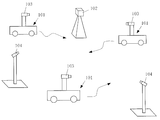
- FIG. 6 is a schematic diagram of a robot system including a motion prediction control apparatus according to the second embodiment of the present invention.
- 101 is a mobile robot
- 102 is a landmark fixed to the outside of the mobile robot 101
- 103 is an internal sensor fixed to the mobile robot 101
- 104 is an external sensor fixed to the outside of the mobile robot 101.
- a plurality of mobile robots 101 can move autonomously.
- the mobile robot is simply referred to as “robot”.
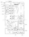
- FIG. 7 is a first configuration example of a motion prediction control apparatus according to the second embodiment of the present invention.
- the motion prediction control device 110 of the second embodiment includes a measurement device 112, a state estimation device 114, a data storage device 116, and a plurality of robot control devices 120.
- Devices 112, 114, 120 are each directly connected to data storage device 116.
- the plurality of robot control devices 120 include a first robot control device 120A, a second robot control device 120B, and a third robot control device 120C.
- the number of robot control devices 120 is three, but may be two or four or more.
- the measuring device 112 is connected to the corresponding external sensor 104 and takes in sensor information (observed values) of the external sensor 104.
- the external sensor 104 include a camera, a laser range finder (LRF), a three-dimensional laser radar, a gyro sensor, a GPS compass, and a pulse encoder.
- the measurement device 112 reads sensor information from the external sensor 104 at an arbitrary timing, and performs measurement processing (operations (1) to (3)) described later.
- the measurement unit 124 on the robot control device 120 has the same function as the measurement device 112.
- the configuration of the robot control device 120 described later that does not have a moving mechanism or a processing unit for drive control is referred to as a “measurement device 112”.
- the state estimation device 114 is implemented with a state estimation algorithm based on the Kalman filter algorithm.
- state variables such as the position x, y, z, velocity vx, vy, vz, angular velocity drx, dry, drz of the robot 101 are collectively defined as an internal state X.
- a state transition equation X (t + ⁇ t) f (X (t)) indicating how the internal state X changes with time
- an observation equation Y h that associates the internal state X with the observed value Y.
- (X) An observation equation is defined for each type of observation value Y (sensor information).
- this algorithm and the error distribution C ov X of internal state X, manages and error distribution C ov Y observations Y, can be determined the accuracy of the state estimation from these data.
- these accuracy index values are collectively referred to as E.
- the state estimation device 114 is provided with two functions of an overall prediction unit 115a and an update unit 115b.
- the overall prediction unit 115a performs a calculation of causing the internal state X recorded in the data storage device 116 to transition to a designated time using the state transition equation f (X).
- the update unit 115b uses the overall prediction unit 115a to transition to the measurement time and uses the observation equation h (X) and the predicted value of the observed value Y of the target (robot 101 or landmark 102). Is calculated.
- the input observed value Y and the predicted value are compared, and the internal state X is updated and recorded in the data storage device 116.
- the state estimation accuracy index value E is also updated and recorded in the data storage device 116.
- the robot control device 120 in FIG. 7 shows a configuration used in a general robot 101.
- a robot control device 120 performs a sensor process of a driving unit 121 for movement, a vehicle control unit 122 that controls the driving unit 121, an action planning unit 123 that calculates a target trajectory of the robot 101, and each sensor 103.
- the measuring unit 124 is configured.
- the sensors 103 are mainly used for measuring the angular velocity or acceleration of the robot 101, the distance measuring sensor 103b (LRF) for measuring the surrounding shape, and the amount of rotation of the wheels provided in the robot 101. This is the wheel encoder 103c.
- FIG. 8 is a second configuration example of the motion prediction control apparatus according to the second embodiment of the present invention.
- the type of the sensor 103 is not limited. That is, for example, as shown in FIG. 8, sensors such as a camera 103d, a GPS compass 103e, and a steering angle encoder 103f for measuring the steering angle of wheels provided in the robot 101 may be added, or some sensors may be used. There may be no configuration.
- other points may be the same as those of the first configuration example of the motion prediction control apparatus.
- the action planning unit 123 is a real-time processing system that operates at a constant control cycle, and predicts the current or future position or posture of the robot 101 using the on-robot prediction unit 123a. It is used for calculation of the target trajectory of the robot 101 by the trajectory generation unit 123b. Moreover, the present or future position or posture of the other robot 101 is predicted as necessary, such as in the case of collision avoidance.
- the on-robot prediction unit 123a performs a calculation for transitioning a state quantity related to robot control from the internal state X recorded in the data storage device 116 to a specified time using the state transition equation f (X). I do.
- the on-robot prediction unit 123a is designed to perform prediction processing under the time constraint of real-time control.
- the vehicle control unit 122 is a real-time processing system that operates at a constant control cycle, and controls the drive unit 121 by calculating a command value using the command value calculation unit 122a so that the robot 101 moves along the target trajectory.
- the communication unit 125 has a data communication function between the robot 101 (that is, the robot control device 120 provided in the robot 101) and the data storage device 116. Specifically, a device that performs wired communication such as Ethernet (registered trademark) or USB, or wireless communication such as Bluetooth (registered trademark) or wireless LAN is used.
- wired communication such as Ethernet (registered trademark) or USB
- wireless communication such as Bluetooth (registered trademark) or wireless LAN is used.
- the data storage device 116 holds data such as the internal state X, the model time tx of the internal state, the observed value Y, the measured time ty, the state transition equation f, the observation equation h, and the state estimation accuracy index value E.
- the measuring device 112 or the measuring unit 124 repeats the following (1) to (3) at an arbitrary timing.
- Acquire sensor information at an arbitrary timing For example, in the case of a camera, a shutter signal is transmitted to the camera, and a captured image is acquired.
- the acquired sensor information is processed, and an observed value Y such as the position and posture of the robot 101 or the landmark 102 and the speed or angular velocity of the robot 101 is obtained. Since the observed value Y differs for each sensor, it is defined for each sensor.
- the sensor information processing performed here also differs depending on the type of sensor.
- sensor information on the position and orientation of an object is acquired from the obtained image by image processing (eg, a white area in the image is extracted to obtain the center of gravity).
- image processing e.g, a white area in the image is extracted to obtain the center of gravity.
- a pulse wave counting process or the like can be considered.
- the calculated observed value Y, the measured time ty (such as shutter time), and the error distribution C ov Y of the observed value Y are recorded in the data storage device 116.
- the state estimation device 114 performs the following (4) to (6) every time the observed value Y is updated.
- the data storage device 116 is monitored, and if a new observed value Y is recorded, Y, ty, X, tx, f, h, E are read from the data storage device 116.
- the observed value at the time ty is predicted from the internal state predicted in (5), and the predicted value and the observed value Y are compared to correct (update) the internal state X. .
- the updating unit 115 b calculates an accuracy distribution value E such as the error distribution C ov X of the internal state X and the magnitude of the difference between the observed value and the predicted value, and records it in the data storage device 116.
- the action planning unit 123 on the robot control device 120 repeats the following (7) to (8) at a constant cycle.
- the current position and future position of the robot 101 are calculated using the robot prediction unit 123a. Further, the current position and future position of the other robot 101 are calculated as necessary for collision avoidance and the like.
- a target trajectory is generated so that the robot 101 moves to the target position.
- the vehicle control unit 122 on the robot control device 120 repeats the following (9) to (11) at a constant cycle.
- the current speed of the robot 101 is obtained from the wheel encoder 103c.
- a control command value that moves along the target trajectory generated by the action planning unit 123 is calculated.
- the calculated control command value is transmitted to the drive unit 121.
- the vehicle control unit 122 needs to calculate a control command value at a constant period. Further, the target trajectory referred to by the vehicle control unit 122 needs to be generated in advance by the action planning unit 123. Therefore, the process of the action plan part 123 and the vehicle control part 122 is a real-time process repeated with a fixed period.
- the control cycle of the action planning unit 123 is longer than the control cycle of the vehicle control unit 122 (depending on the length of the target trajectory generated at one time).
- the target trajectory includes a rough movement route to the target point in addition to the latest movement route referred to by the vehicle control unit 122. Therefore, the action planning unit 123 may be further divided into two or more processes such as local route generation, global route generation, and global route generation. In this case, the process of generating a local route is a shorter control cycle.
- the global region may be a long control cycle or non-real-time processing in which the cycle is not constant.
- FIG. 9 is a third configuration example of the motion prediction control apparatus according to the second embodiment of the present invention.
- the robot control device 120 further includes an on-robot storage unit 126.
- the on-robot prediction unit 123a refers to the latest internal state X in the data storage device 116.
- the predicted value may not be obtained under a certain time constraint. Therefore, in this example, the contents of the data storage device 116 are sequentially transferred to the on-robot storage unit 126, and the on-robot prediction unit 123a refers to the on-robot storage unit 126.
- the transfer timing is when the internal state X of the data storage device 116 is updated (immediately after (6) described above).
- the second robot control device 120B and the third robot control device 120C also include an on-robot prediction unit 123a, an on-robot storage unit 126, and the like.
- the number of robot control devices 120 is three, but may be two or four or more.
- other points may be the same as those of the first configuration example or the second configuration example of the motion prediction control apparatus.
- FIG. 10 is a fourth configuration example of the motion prediction control apparatus according to the second embodiment of the present invention.
- the expression “measuring device 112” is used for explanation, but the measuring device 112 is provided in the robot control device 120 (that is, the robot 101) that does not have a moving mechanism. Treat as a kind. Therefore, it is assumed that the system configuration in the second embodiment of the present invention includes two types of state estimation device 114 and robot control device 120, and robot control device 120 (robot 101) includes one that does not have a moving mechanism.
- the data storage device 116 may be a shared memory in which a plurality of devices and programs read and write the same data.
- the state estimation device 114 may be installed on any of the robots 101 and integrated with the robot control device 120 as shown in FIG.
- a plurality of programs can be processed in parallel on one PC as a state estimation program and a robot control program.
- other points may be the same as those of the first configuration example, the second configuration example, or the third configuration example of the motion prediction control apparatus.
- the predicted value calculated by the on-robot prediction unit 123a is used for the control of the robot 101.
- the robot 101 measures surrounding people and objects, and the information on the position and motion is detected by the on-robot prediction unit 123a. It can also be used for services that present information that changes in real time, such as predicting and presenting to people.
- the measurement device 112, the state estimation device 114, and the data storage device 116 can be used to detect an object or a plurality of objects at an arbitrary timing that does not depend on the control cycle of the robot 101.
- the sensor information of the robot 101 is acquired, the internal state X of each robot 101 at the same time as the time when the sensor information is acquired is predicted, the predicted internal state is updated by comparing with the sensor information, and the updated internal state Since X and the state transition equation f (X) used for the prediction are stored, the motion prediction of each robot 101 is performed based on the object (for example, the landmark 102) and the sensor information (for example, the position and orientation) of the robot 101. Can do.
- the plurality of robot control devices 120 predict the predicted value required for each robot 101 based on the latest internal state X stored in the data storage device 116, it is not affected by the calculation amount of the state estimation. It is possible to control a plurality of robots 101 by calculating a control command value at a control cycle determined for each robot 101.
- each robot control device 120 can operate without being affected by the time required for the state estimation update process. Also, when the number of measuring devices 112 and robot control devices 120 increases and the amount of calculation for state estimation increases, the time required for the prediction process does not increase because each robot control device 120 performs prediction calculation independently. Therefore, it is not necessary to review the design of arithmetic processing capacity when the system is changed. Furthermore, the time constraint of the prediction process can be set for each robot control device 120. In addition, the accuracy of the predicted value to be calculated, the type of predicted value, and the like can be set for each robot control device 120. Therefore, each robot 101 can realize a device such as changing the accuracy of prediction calculation or calculating only necessary variables in the internal state X in consideration of the time required for the prediction process, the control cycle, and the like.
- the data storage device 116 transfers the latest internal state X stored in the data storage device 116 to the on-robot storage unit 126 at a timing that does not depend on the request from the robot 101, so that the state of the robot control device 120 Even when the communication between the estimation devices 114 takes a long time or when the required communication time is not constant, the data necessary for the prediction process can be referred to immediately. In this case, the data referred on the robot does not necessarily become the latest value due to the influence of communication delay, but the prediction process can be completed within a certain time.
- the second embodiment of the present invention is not limited to the above-described configuration example, is shown by the description of the scope of claims, and further includes meanings equivalent to the description of the scope of claims and all modifications within the scope. It is a waste.
- FIG. 11 is a configuration example of a robot system having a motion prediction control apparatus according to the third embodiment of the present invention.
- 201 is an object (work)
- 202 is a robot
- 203 is a robot arm
- 204 is a hand
- 205a is a first camera fixed to the hand 204
- 205b is a second camera fixed to an external fixed position.
- 210 is a motion prediction control device.
- a workpiece 201 that moves while moving in a pendulum is measured by cameras 205 a and 205 b
- the robot 202 is controlled to follow the workpiece 201
- the workpiece 201 is gripped by the hand 204.
- FIG. 12 is a configuration example of a motion prediction control apparatus according to the third embodiment of the present invention.
- the motion prediction control device 210 includes a measurement device 212, a state estimation device 214, and a robot control device 220.
- the state estimation device 214 includes a data storage device 216.
- the measuring device 212 measures the position and orientation of the object 201.
- the measurement device 212 includes two measurement devices (a first measurement device 212a and a second measurement device 212b) connected to the first camera 205a and the second camera 205b, respectively.
- two cameras and two measuring devices are used, images of the object 201 are captured from the first camera 205a and the second camera 205b, and the position and orientation of the object 201 are obtained by image processing.
- the obtained position and orientation of the object 201 are stored in the data storage device 216.
- the measurement device 212 is not limited to this configuration, and a measurement device capable of three-dimensionally measuring the position of the object 201, for example, a laser radar may be used.
- the state estimation device 214 estimates (updates) the internal state of the object 201 including the accuracy index value E (described later) from the measurement result obtained by measuring the object 201 based on the state transition model and the observation model, and It has a function of determining whether or not the object 201 can be gripped from the accuracy index value E.
- a state estimation algorithm based on the Kalman filter algorithm is implemented in the state estimation device 214.
- the following four are defined as “state transition models”.
- Internal state at time t 0: X 0
- Covariance of initial condition X 0 C ov X 0
- State transition equation: X t + ⁇ t f (X t , ⁇ t) (1)
- state variables such as the swing angle ⁇ , the angular velocity ⁇ , and the fulcrum positions x, y, and z of the pendulum on which the object 201 is suspended are collectively defined as an internal state X.
- a covariance C ov X 0 is defined that predicts how large the difference between the initial condition and the actual one will be.
- the state transition equation (1) shows how the internal state X changes with time. In the case of this example, the state transition equation is defined from the equation of motion of the pendulum and the fact that the fulcrum position moves at a constant linear velocity.
- the Kalman filter defines the “observation model” (observation equation and observation noise) of equations (2) and (3) with the position and orientation of the object 201 calculated by the measurement device 212 as the measurement value Y.
- Observation equation: Y t g (X t ) (2)
- Observation equation (2) is an equation that associates the internal state X with the measured value Y.
- the observation noise (3) is a covariance representing how much measurement error is included in the measurement at time t, and is determined by the resolution of the camera and the orientation of the viewpoint.
- the observation noise (3) is not a fixed value, but is calculated by the measurement device 212 for each image and is passed to the state estimation device 214 together with the measurement value.
- the robot control device 220 has a function of controlling the robot 202 so as to perform a gripping operation by predicting the movement destination of the object 201 based on the estimation result (update result) of the internal state when it can be gripped.
- Robot control device 220 receives hand position information from robot 202 and transmits hand speed command values and hand opening / closing command values. These transmission and reception are performed at a constant control cycle (4 ms cycle).
- the measurement device 212 measures the position and orientation of the object 201 as sensor information.
- the state estimation device 214 estimates (updates) the internal state of the object 201 including the accuracy index value E based on the state transition model, and (C) the accuracy index value. Whether or not the object 201 can be gripped is determined from E.
- the robot controller 220 predicts the movement destination of the object 201 based on the estimation result of the internal state and causes the robot 202 to perform a gripping operation.
- the robot 202 is moved by the robot controller 220 so that the measurement of the position and orientation of the object 201 can be continued.
- the accuracy index value E includes an error between a predicted value obtained by predicting the position and orientation of the object 201 and an actual measurement value thereof, and a covariance matrix that predicts the variance of the error based on the state transition model and the observation model.
- the first threshold value and the second threshold value are arbitrary threshold values set in advance.
- the error less than a square third threshold Mahalanobis distance M t divided by the covariance matrix and, when the trace of the covariance matrix is less than the fourth threshold value, determines that the graspable May be.
- the third threshold value and the fourth threshold value are arbitrary threshold values set in advance.
- the measurement device 212 (the first measurement device 212a and the second measurement device 212b) transmits a shutter signal to each of the two cameras (the first camera 205a and the second camera 205b) at an arbitrary timing, and is imaged. Get an image.
- Information (measurement value Y) of the position and orientation of the object 201 is acquired from the obtained image by image processing by the measurement device 212. For example, a white area in the image is extracted and the center of gravity is obtained.
- the time when the shutter signal is transmitted from the measuring device 212 is ty.
- the state estimation device 214 corrects the internal state X by comparing the measured value Y with the predicted value Ym of Y predicted by the state transition model and the observation model. Also, an accuracy index value E representing the accuracy of predicting the position of the object 201 is calculated. The internal state is updated at an arbitrary timing that does not depend on the control cycle of the robot controller 220.
- the robot control device 220 refers to the result of the state estimation device 214 for each control cycle, evaluates the accuracy index value E, and determines whether to start the gripping operation.
- a time width ⁇ t for state transition is calculated from the measurement time ty and the current model time t.
- the initial value of the model time t is the time when measurement is started. Further, the measurement time may be defined as an elapsed time with the start time as a base point, and the initial value of the model time may be set to zero.
- K t + ⁇ t (C ov X t + ⁇ t
- the internal state is corrected (that is, updated) based on the observed value at time ty.
- the internal state is updated at an arbitrary timing that does not depend on the control cycle of the robot controller 220. Therefore, as the entire system repeats the processes (a1) to (a6), the internal state gradually approaches a true value (actual speed of the object, etc.).
- the state estimation device 214 calculates an accuracy index value E representing the accuracy of the current state estimation as follows after the processing from (b1) to (b9).
- the accuracy index value E is calculated by any of the following (c1), (c2), and (c3).
- equation (16) in (c1) is an evaluation equation for model fitness of a normal distribution
- equation (18) in (c3) is an information criterion (AIC).
- Expression (17) of (c2) is characterized in that a covariance C ov Y trace is used as the denominator.
- the square root of the covariance determinant represents the volume of the distribution of eY.
- the square root of the trace represents the radius of the smallest sphere that wraps around the distribution.
- FIG. 13 is an overall flowchart of the motion prediction control method according to the third embodiment of the present invention. As shown in this figure, the motion prediction control method includes steps (steps) S1 to S12.
- hand position information is received from the robot 202.
- the communication with the robot 202 is managed by the robot 202 so as to be performed, for example, with a control period of 4 ms. Therefore, the robot controller 220 must wait until data is received, and complete the transmission process of S12 within a control period of, for example, 4 ms after receiving the data.
- a flag F indicating that the gripping operation is being performed is determined. The flag F is initialized to false at the start of the program.
- the determination means uses any of the following (d1) to (d3).
- the object 201 is out of the field of view of one camera and measurement is continued with only one camera.
- the covariances C ov Y and V are covariance matrices indicating a long and narrow distribution in the viewing direction of the camera.
- the gripping operation may be started.
- Vx Kpx ⁇ (mx ⁇ rx) + Kdx ⁇ (mx ⁇ rx ⁇ pr_x) (19)
- Vy Kpy ⁇ (my ⁇ ry) + Kdy ⁇ (my ⁇ ry ⁇ pr_y) (20)
- Vz Kpz ⁇ (mz ⁇ rz) + Kdz ⁇ (mz ⁇ rz ⁇ pr_z) (21)
- This control is PD control, where mx, my, and mz are the current position [mm] of the measured object, and rx, ry, and rz are the current position [mm on the camera's line of sight] [mm]. ], Pr_x, pr_y, pr_z are position deviations (my-ry, mz-rz, etc.) calculated in the previous step, Kp is a position control gain, and Kd is a differential control gain.
- the gripping operation flag F is set to true when the gripping operation is started.
- the target speed of the robot arm 203 is calculated so that the robot arm 203 moves to the gripping position A during the gripping operation.
- the gripping operation flag F is set to false. When the gripping operation is not terminated, the gripping operation flag F remains true, so that the gripping operation is continued from the next time due to the branch of S2.
- the calculated target speed and hand opening / closing command value are transmitted to the robot 202.
- the Kalman filter is used as a method for estimating the motion state of the object 201.
- any other method may be used as long as it is a state estimation method that satisfies the following conditions.
- a particle filter or a least square method can be applied.
- the future state can be predicted by estimating the motion state of the object 201.
- E2 A covariance matrix representing the variance of the prediction error when a future position is predicted can be calculated.
- FIG. 14 is a diagram illustrating the relationship between the elapsed time and the accuracy index value E in the embodiment. This example is a result of calculating the accuracy index value E by the above-described equation (17) of (c2).
- the accuracy index value E gradually increases from the start of measurement, and stabilizes at 80 or more after 2 seconds from the start of measurement. Therefore, it can be said that the gripping failure is unlikely to occur when the gripping operation start condition is that the accuracy index value E of Expression (17) is 80 or more.
- the accuracy index value may temporarily increase as seen in the elapsed time around 1 second. Therefore, as in (c3) described above, it is preferable to make a determination in consideration of accuracy index values for the past several points.
- the average value of past several points exceeds 80, or exceeds 80 continuously for a certain time.
- the accuracy index value exceeds 80 continuously for 120 ms or longer” may be set as the gripping operation start condition.
- the measurement apparatus 212 and the state estimation apparatus 214 measure the position or orientation of the object 201 and estimate the internal state of the object 201. Even if it is a motion other than a fast linear motion, a uniform circular motion, and a uniform acceleration linear motion, the motion of the target 201 is predicted based on the internal state (for example, position, posture, speed, angular velocity) of the target 201 (for example, a workpiece). can do.
- the internal state for example, position, posture, speed, angular velocity
- the state estimation device 214 estimates the internal state of the object 201 including the accuracy index value E based on the state transition model and the observation model, and determines whether or not the object 201 can be gripped from the accuracy index value E.
- the robot controller 220 moves the robot 202 so that measurement of the position and orientation of the object 201 can be continued, for example, so that gripping failure can be avoided even when the prediction accuracy decreases. be able to.
- the robot controller 220 predicts the movement destination of the target object 201 based on the estimation result of the internal state and grips the robot 202. Therefore, the robot 202 is made to follow the target object 201. It can be securely gripped.
- the object 201 is moved and the robot 202 is fixed.
- the third embodiment of the present invention is not limited to this example, and the object is moved even when the robot moves without moving the object. And both robots may move. Therefore, “movement of the object” in the third embodiment of the present invention means relative movement of the object as viewed from the robot.
- the third embodiment of the present invention is not limited to the above-described configuration example, is shown by the description of the scope of claims, and further includes all modifications within the meaning and scope equivalent to the description of the scope of claims. It is a waste.
Abstract
L'invention porte sur la prédiction du mouvement. (A) Une information de capteurs est acquise par la mesure d'un ou de chacun d'un objet cible et d'un robot (2) à l'aide de dispositifs de mesure (12a, 12b). (B) Les états internes d'un ou de chacun de l'objet cible et du robot (2) sont prédits et mis à jour par un dispositif d'estimation d'état (14) sur la base de l'information de capteurs. (C) Les états internes sont stockés à l'aide d'un dispositif de stockage de données (16). (D) Le robot (2) est commandé par un dispositif de commande de robot (20). Dans (B), les états internes sont mis à jour par le dispositif d'estimation d'état (14) avec un programme choisi qui ne dépend pas du cycle de commande du robot. Dans (B), la valeur de prédiction nécessaire pour la commande du robot est calculée par le dispositif de commande du robot avec la périodicité du cycle de commande sur la base des états internes les plus récents qui sont stockés dans le dispositif de stockage de données (16)
Priority Applications (3)
| Application Number | Priority Date | Filing Date | Title |
|---|---|---|---|
| CN201280022935.9A CN103517789B (zh) | 2011-05-12 | 2012-04-24 | 运动预测控制装置和方法 |
| EP12782445.6A EP2708334B1 (fr) | 2011-05-12 | 2012-04-24 | Dispositif et procédé pour contrôler la prédiction du mouvement |
| US14/078,342 US9108321B2 (en) | 2011-05-12 | 2013-11-12 | Motion prediction control device and method |
Applications Claiming Priority (6)
| Application Number | Priority Date | Filing Date | Title |
|---|---|---|---|
| JP2011106822A JP5733516B2 (ja) | 2011-05-12 | 2011-05-12 | 移動体把持装置と方法 |
| JP2011-106822 | 2011-05-12 | ||
| JP2011-116663 | 2011-05-25 | ||
| JP2011116883A JP5679121B2 (ja) | 2011-05-25 | 2011-05-25 | ロボットの運動予測制御方法と装置 |
| JP2011116663A JP5733518B2 (ja) | 2011-05-25 | 2011-05-25 | 運動予測制御装置と方法 |
| JP2011-116883 | 2011-05-25 |
Related Child Applications (1)
| Application Number | Title | Priority Date | Filing Date |
|---|---|---|---|
| US14/078,342 Continuation US9108321B2 (en) | 2011-05-12 | 2013-11-12 | Motion prediction control device and method |
Publications (1)
| Publication Number | Publication Date |
|---|---|
| WO2012153629A1 true WO2012153629A1 (fr) | 2012-11-15 |
Family
ID=47139115
Family Applications (1)
| Application Number | Title | Priority Date | Filing Date |
|---|---|---|---|
| PCT/JP2012/060918 WO2012153629A1 (fr) | 2011-05-12 | 2012-04-24 | Dispositif et procédé pour contrôler la prédiction du mouvement |
Country Status (4)
| Country | Link |
|---|---|
| US (1) | US9108321B2 (fr) |
| EP (1) | EP2708334B1 (fr) |
| CN (1) | CN103517789B (fr) |
| WO (1) | WO2012153629A1 (fr) |
Cited By (4)
| Publication number | Priority date | Publication date | Assignee | Title |
|---|---|---|---|---|
| CN104802174A (zh) * | 2013-10-10 | 2015-07-29 | 精工爱普生株式会社 | 机器人控制系统、机器人、程序以及机器人控制方法 |
| CN109866206A (zh) * | 2017-11-24 | 2019-06-11 | 株式会社安川电机 | 机器人系统以及机器人系统的控制方法 |
| CN111360829A (zh) * | 2020-03-13 | 2020-07-03 | 哈尔滨工程大学 | 人工智能大数据下医疗用品运送机器人及其控制方法 |
| CN113687652A (zh) * | 2015-09-10 | 2021-11-23 | 波士顿动力公司 | 使用时空对象清单确定监测参数的系统和方法 |
Families Citing this family (32)
| Publication number | Priority date | Publication date | Assignee | Title |
|---|---|---|---|---|
| JP2013022705A (ja) | 2011-07-25 | 2013-02-04 | Sony Corp | ロボット装置及びロボット装置の制御方法、コンピューター・プログラム、並びにロボット・システム |
| CN103895017B (zh) * | 2014-03-14 | 2015-09-09 | 北京邮电大学 | 一种基于使用可靠度的空间机械臂控制方法及系统 |
| JP6364836B2 (ja) * | 2014-03-14 | 2018-08-01 | セイコーエプソン株式会社 | ロボット、ロボットシステム、及び制御装置 |
| CN103991074B (zh) * | 2014-05-21 | 2015-10-21 | 北京邮电大学 | 一种基于粒子滤波算法的空间机械臂控制方法及系统 |
| WO2016004587A1 (fr) * | 2014-07-08 | 2016-01-14 | 北京航空航天大学 | Cadre d'application de système hybride robotique basé sur une architecture de processeur multicoeur |
| US9597801B2 (en) * | 2014-10-21 | 2017-03-21 | Centurylink Intellectual Property Llc | Automated data center |
| US9889566B2 (en) * | 2015-05-01 | 2018-02-13 | General Electric Company | Systems and methods for control of robotic manipulation |
| US10059004B2 (en) * | 2015-06-22 | 2018-08-28 | Ricoh Company, Ltd. | Robot, information processing system, and storage medium |
| JP6077617B1 (ja) * | 2015-09-25 | 2017-02-08 | ファナック株式会社 | 最適な速度分布を生成する工作機械 |
| JP6711591B2 (ja) * | 2015-11-06 | 2020-06-17 | キヤノン株式会社 | ロボット制御装置およびロボット制御方法 |
| GB2563785B (en) * | 2016-03-28 | 2021-03-03 | Groove X Inc | Autonomously acting robot that performs a greeting action |
| JP6544878B2 (ja) * | 2016-05-16 | 2019-07-17 | 本田技研工業株式会社 | 車両制御システム、車両制御方法、および車両制御プログラム |
| JP6444940B2 (ja) * | 2016-05-17 | 2018-12-26 | ファナック株式会社 | 被加工物保持システム |
| JP6514156B2 (ja) | 2016-08-17 | 2019-05-15 | ファナック株式会社 | ロボット制御装置 |
| EP3324360A4 (fr) * | 2016-09-13 | 2019-05-08 | Hitachi Information & Telecommunication Engineering, Ltd. | Dispositif et procédé de prédiction d'état |
| JP2018126796A (ja) * | 2017-02-06 | 2018-08-16 | セイコーエプソン株式会社 | 制御装置、ロボットおよびロボットシステム |
| DE102017005194C5 (de) * | 2017-05-31 | 2022-05-19 | Kuka Deutschland Gmbh | Steuern einer Roboteranordnung |
| DE102017115833A1 (de) * | 2017-07-13 | 2019-01-17 | SW Automation GmbH | Verfahren zum Betreiben einer Werkstück-Bearbeitungs-Anlage und Werkstück-Bearbeitungs-Anlage |
| US11453123B2 (en) * | 2017-12-27 | 2022-09-27 | Stmicroelectronics, Inc. | Robotic device with time-of-flight proximity sensing system |
| CN111615443B (zh) * | 2018-01-23 | 2023-05-26 | 索尼公司 | 信息处理装置、信息处理方法和信息处理系统 |
| SG11202010344QA (en) | 2018-06-22 | 2020-11-27 | Soft Servo Systems Inc | Motion control program, motion control method, and motion control device |
| US11392103B2 (en) | 2018-06-22 | 2022-07-19 | Soft Servo Systems, Inc. | Motion control program, motion control method, and motion control device |
| JP6473917B1 (ja) * | 2018-06-22 | 2019-02-27 | ソフトサーボシステムズ株式会社 | モーション制御プログラム、モーション制御方法及びモーション制御装置 |
| CN110733034B (zh) * | 2018-07-20 | 2022-10-21 | 台达电子工业股份有限公司 | 机械手臂校正方法、机械手臂校正系统以及输送系统 |
| JP6878391B2 (ja) | 2018-12-18 | 2021-05-26 | ファナック株式会社 | ロボットシステムとその調整方法 |
| JP7178931B2 (ja) * | 2019-03-11 | 2022-11-28 | 本田技研工業株式会社 | センサ配置態様の取得装置 |
| JP7207207B2 (ja) * | 2019-07-09 | 2023-01-18 | トヨタ自動車株式会社 | 演算装置、機械学習方法及び制御プログラム |
| CN110355788A (zh) * | 2019-07-24 | 2019-10-22 | 哈尔滨工业大学(深圳) | 移动操作机器人大尺度空间高精度在线标定系统 |
| JP7358994B2 (ja) * | 2020-01-08 | 2023-10-11 | オムロン株式会社 | ロボット制御装置、ロボット制御システム、ロボット制御方法及びロボット制御プログラム |
| WO2021147035A1 (fr) | 2020-01-22 | 2021-07-29 | Abb Schweiz Ag | Système et procédé d'actionnement de robot, dispositif électronique et support lisible par ordinateur |
| US20220176564A1 (en) | 2020-12-04 | 2022-06-09 | GM Global Technology Operations LLC | Accurate position control for fixtureless assembly |
| CN117182928B (zh) * | 2023-11-03 | 2024-01-26 | 深圳市磐锋精密技术有限公司 | 一种智能抓取机器手同步控制系统 |
Citations (4)
| Publication number | Priority date | Publication date | Assignee | Title |
|---|---|---|---|---|
| JPH0719818A (ja) * | 1993-06-30 | 1995-01-20 | Kajima Corp | 3次元運動予測装置 |
| JPH1124718A (ja) * | 1997-07-07 | 1999-01-29 | Toshiba Corp | ロボットの制御装置及び制御方法 |
| JPH11327620A (ja) * | 1998-05-20 | 1999-11-26 | Yaskawa Electric Corp | 数値制御装置における位置指令方法および装置 |
| JP2011209203A (ja) * | 2010-03-30 | 2011-10-20 | Sony Corp | 自己位置推定装置および自己位置推定方法 |
Family Cites Families (17)
| Publication number | Priority date | Publication date | Assignee | Title |
|---|---|---|---|---|
| JP4153625B2 (ja) | 1999-08-19 | 2008-09-24 | 株式会社トキメック | 運動予測装置 |
| JP4265088B2 (ja) | 2000-07-10 | 2009-05-20 | 株式会社豊田中央研究所 | ロボット装置及びその制御方法 |
| JP4072017B2 (ja) * | 2002-08-02 | 2008-04-02 | 日本放送協会 | 状態推定装置、その方法及びそのプログラム、並びに、現在状態推定装置及び未来状態推定装置 |
| WO2006079617A1 (fr) * | 2005-01-26 | 2006-08-03 | Abb Ab | Dispositif et procede d'etalonnage du point central d'un outil monte sur un robot au moyen d'un appareil photographique |
| JP4504228B2 (ja) * | 2005-03-01 | 2010-07-14 | 川崎重工業株式会社 | ロボットの制御装置および制御方法 |
| JP2007090448A (ja) * | 2005-09-27 | 2007-04-12 | Honda Motor Co Ltd | 二次元コード検出装置及びそのプログラム、並びに、ロボット制御情報生成装置及びロボット |
| EP1815972B1 (fr) * | 2006-02-06 | 2013-12-18 | ABB Research Ltd. | Système de train de presses et procédé |
| JP2007316966A (ja) * | 2006-05-26 | 2007-12-06 | Fujitsu Ltd | 移動ロボット、その制御方法及びプログラム |
| US8676379B2 (en) * | 2006-07-04 | 2014-03-18 | Panasonic Corporation | Device and method for controlling robot arm, robot, and robot arm control program |
| JP4836872B2 (ja) * | 2007-05-31 | 2011-12-14 | 株式会社東芝 | 制御装置、制御方法、プログラム及びロボット |
| CN101216711A (zh) * | 2008-01-08 | 2008-07-09 | 哈尔滨工程大学 | 两栖机械螃蟹的分级控制装置及控制方法 |
| KR101686517B1 (ko) * | 2009-05-22 | 2016-12-14 | 도요타지도샤 히가시니혼 가부시키가이샤 | 작업 지원 로봇 시스템 |
| CN101920498A (zh) * | 2009-06-16 | 2010-12-22 | 泰怡凯电器(苏州)有限公司 | 实现室内服务机器人同时定位和地图创建的装置及机器人 |
| CN101630413B (zh) * | 2009-08-14 | 2012-01-25 | 浙江大学 | 一种多机器人跟踪移动目标方法 |
| KR101633362B1 (ko) * | 2010-01-18 | 2016-06-28 | 삼성전자 주식회사 | 인간형 로봇 및 그 보행 제어방법 |
| JP4850956B2 (ja) * | 2010-02-19 | 2012-01-11 | ファナック株式会社 | 学習制御機能を備えたロボット |
| CN101943916B (zh) * | 2010-09-07 | 2012-09-26 | 陕西科技大学 | 一种基于卡尔曼滤波器预测的机器人避障方法 |
-
2012
- 2012-04-24 WO PCT/JP2012/060918 patent/WO2012153629A1/fr active Application Filing
- 2012-04-24 CN CN201280022935.9A patent/CN103517789B/zh active Active
- 2012-04-24 EP EP12782445.6A patent/EP2708334B1/fr active Active
-
2013
- 2013-11-12 US US14/078,342 patent/US9108321B2/en active Active
Patent Citations (4)
| Publication number | Priority date | Publication date | Assignee | Title |
|---|---|---|---|---|
| JPH0719818A (ja) * | 1993-06-30 | 1995-01-20 | Kajima Corp | 3次元運動予測装置 |
| JPH1124718A (ja) * | 1997-07-07 | 1999-01-29 | Toshiba Corp | ロボットの制御装置及び制御方法 |
| JPH11327620A (ja) * | 1998-05-20 | 1999-11-26 | Yaskawa Electric Corp | 数値制御装置における位置指令方法および装置 |
| JP2011209203A (ja) * | 2010-03-30 | 2011-10-20 | Sony Corp | 自己位置推定装置および自己位置推定方法 |
Non-Patent Citations (1)
| Title |
|---|
| See also references of EP2708334A4 * |
Cited By (7)
| Publication number | Priority date | Publication date | Assignee | Title |
|---|---|---|---|---|
| CN104802174A (zh) * | 2013-10-10 | 2015-07-29 | 精工爱普生株式会社 | 机器人控制系统、机器人、程序以及机器人控制方法 |
| CN113687652A (zh) * | 2015-09-10 | 2021-11-23 | 波士顿动力公司 | 使用时空对象清单确定监测参数的系统和方法 |
| CN109866206A (zh) * | 2017-11-24 | 2019-06-11 | 株式会社安川电机 | 机器人系统以及机器人系统的控制方法 |
| JP2019093481A (ja) * | 2017-11-24 | 2019-06-20 | 株式会社安川電機 | ロボットシステム及びロボットシステムの制御方法 |
| US11241796B2 (en) | 2017-11-24 | 2022-02-08 | Kabushiki Kaisha Yaskawa Denki | Robot system and method for controlling robot system |
| CN111360829A (zh) * | 2020-03-13 | 2020-07-03 | 哈尔滨工程大学 | 人工智能大数据下医疗用品运送机器人及其控制方法 |
| CN111360829B (zh) * | 2020-03-13 | 2023-12-05 | 苏州三百亿科技有限公司 | 人工智能大数据下医疗用品运送机器人及其控制方法 |
Also Published As
| Publication number | Publication date |
|---|---|
| EP2708334A1 (fr) | 2014-03-19 |
| CN103517789B (zh) | 2015-11-25 |
| EP2708334B1 (fr) | 2020-05-06 |
| US20140074291A1 (en) | 2014-03-13 |
| EP2708334A4 (fr) | 2015-07-01 |
| CN103517789A (zh) | 2014-01-15 |
| US9108321B2 (en) | 2015-08-18 |
Similar Documents
| Publication | Publication Date | Title |
|---|---|---|
| WO2012153629A1 (fr) | Dispositif et procédé pour contrôler la prédiction du mouvement | |
| CN110262495B (zh) | 可实现移动机器人自主导航与精确定位的控制系统及方法 | |
| JP5733518B2 (ja) | 運動予測制御装置と方法 | |
| CN101943916B (zh) | 一种基于卡尔曼滤波器预测的机器人避障方法 | |
| EP3186041B1 (fr) | Tangage et roulis naturels | |
| JP5902425B2 (ja) | ロボット制御装置、外乱判定方法およびアクチュエータ制御方法 | |
| US6704619B1 (en) | Method and system for universal guidance and control of automated machines | |
| KR101475826B1 (ko) | 백스테핑 기법을 이용한 선도 추종자 대형제어 장치, 방법 및 이동로봇 | |
| CN112203812B (zh) | 机器人系统及追加学习方法 | |
| CN114347033B (zh) | 机器人物品抓取方法、装置、机器人及存储介质 | |
| JP2019113926A (ja) | モデル予測制御装置 | |
| JP5679121B2 (ja) | ロボットの運動予測制御方法と装置 | |
| JP4578438B2 (ja) | ロボット装置 | |
| US20040210346A1 (en) | Method and apparatus for allowing mobile robot to return to docking station | |
| WO2020167299A1 (fr) | Systèmes d'impression | |
| JP5169273B2 (ja) | 移動ロボットの制御装置および移動ロボットシステム | |
| Xu et al. | Magnetic locating AGV navigation based on Kalman filter and PID control | |
| Basiuk et al. | Mobile Robot Position Determining Using Odometry Method | |
| JP5733516B2 (ja) | 移動体把持装置と方法 | |
| WO2022126396A1 (fr) | Procédé et appareil de détermination d'informations d'état, plateforme et support de stockage lisible par ordinateur | |
| CN111045428B (zh) | 避障方法、移动机器人及计算机可读存储介质 | |
| CN114643579B (zh) | 一种机器人定位方法、装置、机器人及存储介质 | |
| WO2023066201A1 (fr) | Procédé et appareil de planification de trajet de mouvement de bras mécanique, dispositif, programme et support | |
| US10922154B1 (en) | Systems and methods for inter-process communication within a robot | |
| CN114415655A (zh) | 一种基于改进slam的巡检机器人导航控制方法 |
Legal Events
| Date | Code | Title | Description |
|---|---|---|---|
| 121 | Ep: the epo has been informed by wipo that ep was designated in this application |
Ref document number: 12782445 Country of ref document: EP Kind code of ref document: A1 |
|
| NENP | Non-entry into the national phase |
Ref country code: DE |
|
| WWE | Wipo information: entry into national phase |
Ref document number: 2012782445 Country of ref document: EP |