WO2012153629A1 - Device and method for controlling prediction of motion - Google Patents
Device and method for controlling prediction of motion Download PDFInfo
- Publication number
- WO2012153629A1 WO2012153629A1 PCT/JP2012/060918 JP2012060918W WO2012153629A1 WO 2012153629 A1 WO2012153629 A1 WO 2012153629A1 JP 2012060918 W JP2012060918 W JP 2012060918W WO 2012153629 A1 WO2012153629 A1 WO 2012153629A1
- Authority
- WO
- WIPO (PCT)
- Prior art keywords
- robot
- internal state
- control
- data storage
- state
- Prior art date
Links
Images


Classifications
-
- B—PERFORMING OPERATIONS; TRANSPORTING
- B25—HAND TOOLS; PORTABLE POWER-DRIVEN TOOLS; MANIPULATORS
- B25J—MANIPULATORS; CHAMBERS PROVIDED WITH MANIPULATION DEVICES
- B25J13/00—Controls for manipulators
- B25J13/08—Controls for manipulators by means of sensing devices, e.g. viewing or touching devices
-
- B—PERFORMING OPERATIONS; TRANSPORTING
- B25—HAND TOOLS; PORTABLE POWER-DRIVEN TOOLS; MANIPULATORS
- B25J—MANIPULATORS; CHAMBERS PROVIDED WITH MANIPULATION DEVICES
- B25J19/00—Accessories fitted to manipulators, e.g. for monitoring, for viewing; Safety devices combined with or specially adapted for use in connection with manipulators
- B25J19/02—Sensing devices
- B25J19/021—Optical sensing devices
- B25J19/023—Optical sensing devices including video camera means
-
- B—PERFORMING OPERATIONS; TRANSPORTING
- B25—HAND TOOLS; PORTABLE POWER-DRIVEN TOOLS; MANIPULATORS
- B25J—MANIPULATORS; CHAMBERS PROVIDED WITH MANIPULATION DEVICES
- B25J5/00—Manipulators mounted on wheels or on carriages
- B25J5/007—Manipulators mounted on wheels or on carriages mounted on wheels
-
- B—PERFORMING OPERATIONS; TRANSPORTING
- B25—HAND TOOLS; PORTABLE POWER-DRIVEN TOOLS; MANIPULATORS
- B25J—MANIPULATORS; CHAMBERS PROVIDED WITH MANIPULATION DEVICES
- B25J9/00—Programme-controlled manipulators
- B25J9/16—Programme controls
- B25J9/1656—Programme controls characterised by programming, planning systems for manipulators
- B25J9/1664—Programme controls characterised by programming, planning systems for manipulators characterised by motion, path, trajectory planning
-
- B—PERFORMING OPERATIONS; TRANSPORTING
- B25—HAND TOOLS; PORTABLE POWER-DRIVEN TOOLS; MANIPULATORS
- B25J—MANIPULATORS; CHAMBERS PROVIDED WITH MANIPULATION DEVICES
- B25J9/00—Programme-controlled manipulators
- B25J9/16—Programme controls
- B25J9/1694—Programme controls characterised by use of sensors other than normal servo-feedback from position, speed or acceleration sensors, perception control, multi-sensor controlled systems, sensor fusion
- B25J9/1697—Vision controlled systems
-
- G—PHYSICS
- G05—CONTROLLING; REGULATING
- G05B—CONTROL OR REGULATING SYSTEMS IN GENERAL; FUNCTIONAL ELEMENTS OF SUCH SYSTEMS; MONITORING OR TESTING ARRANGEMENTS FOR SUCH SYSTEMS OR ELEMENTS
- G05B2219/00—Program-control systems
- G05B2219/30—Nc systems
- G05B2219/32—Operator till task planning
- G05B2219/32357—Simulation of material handling, flexible conveyor system fcs
-
- G—PHYSICS
- G05—CONTROLLING; REGULATING
- G05B—CONTROL OR REGULATING SYSTEMS IN GENERAL; FUNCTIONAL ELEMENTS OF SUCH SYSTEMS; MONITORING OR TESTING ARRANGEMENTS FOR SUCH SYSTEMS OR ELEMENTS
- G05B2219/00—Program-control systems
- G05B2219/30—Nc systems
- G05B2219/37—Measurements
- G05B2219/37436—Prediction of displacement, relative or absolute, motion
-
- G—PHYSICS
- G05—CONTROLLING; REGULATING
- G05B—CONTROL OR REGULATING SYSTEMS IN GENERAL; FUNCTIONAL ELEMENTS OF SUCH SYSTEMS; MONITORING OR TESTING ARRANGEMENTS FOR SUCH SYSTEMS OR ELEMENTS
- G05B2219/00—Program-control systems
- G05B2219/30—Nc systems
- G05B2219/40—Robotics, robotics mapping to robotics vision
- G05B2219/40512—Real time path planning, trajectory generation
-
- G—PHYSICS
- G05—CONTROLLING; REGULATING
- G05B—CONTROL OR REGULATING SYSTEMS IN GENERAL; FUNCTIONAL ELEMENTS OF SUCH SYSTEMS; MONITORING OR TESTING ARRANGEMENTS FOR SUCH SYSTEMS OR ELEMENTS
- G05B2219/00—Program-control systems
- G05B2219/30—Nc systems
- G05B2219/41—Servomotor, servo controller till figures
- G05B2219/41146—Kalman filter
-
- G—PHYSICS
- G05—CONTROLLING; REGULATING
- G05B—CONTROL OR REGULATING SYSTEMS IN GENERAL; FUNCTIONAL ELEMENTS OF SUCH SYSTEMS; MONITORING OR TESTING ARRANGEMENTS FOR SUCH SYSTEMS OR ELEMENTS
- G05B2219/00—Program-control systems
- G05B2219/30—Nc systems
- G05B2219/42—Servomotor, servo controller kind till VSS
- G05B2219/42263—Different sample rates, multiple sample rates for the different loops
-
- Y—GENERAL TAGGING OF NEW TECHNOLOGICAL DEVELOPMENTS; GENERAL TAGGING OF CROSS-SECTIONAL TECHNOLOGIES SPANNING OVER SEVERAL SECTIONS OF THE IPC; TECHNICAL SUBJECTS COVERED BY FORMER USPC CROSS-REFERENCE ART COLLECTIONS [XRACs] AND DIGESTS
- Y02—TECHNOLOGIES OR APPLICATIONS FOR MITIGATION OR ADAPTATION AGAINST CLIMATE CHANGE
- Y02P—CLIMATE CHANGE MITIGATION TECHNOLOGIES IN THE PRODUCTION OR PROCESSING OF GOODS
- Y02P90/00—Enabling technologies with a potential contribution to greenhouse gas [GHG] emissions mitigation
- Y02P90/02—Total factory control, e.g. smart factories, flexible manufacturing systems [FMS] or integrated manufacturing systems [IMS]
Definitions
- the present invention relates to a motion prediction control apparatus and method for predicting the motion of a workpiece, a robot, etc., among automatic devices using a robot or the like.
- Sensors and measurement methods used to measure the robot's position and orientation in a control device that calculates and controls the robot's position and orientation using sensor information installed on and outside the robot The following is common.
- a method using an internal sensor on the robot For example, the speed, acceleration, angular velocity, etc. of the robot are measured with a gyro sensor or wheel encoder installed on the robot.
- the steer angle of the robot is measured with the encoder of the steering unit installed on the robot.
- LRF laser range finder
- One or both of the current position and posture of the robot are measured with a GPS compass installed on the robot.
- a method of measuring with an external sensor outside the robot The position and orientation of the robot within the measurement range are measured with a distance measuring sensor or camera installed outside the robot.
- the position and orientation measured in (3) are a relative position and orientation represented by a sensor to be measured and a coordinate system based on a specific point.
- the base points of the measurement coordinates are different from one another, and in the case of a sensor on the robot, the position of the robot itself as the base point is unknown, so it is difficult to compare these measurement results simply by coordinate transformation or the like. Since (1) does not directly measure the position or orientation, it cannot be directly compared with (2) or (3).
- the measurement times of the obtained measurement results may be different. Since the position and posture of the robot change from moment to moment, it is not possible to simply compare measurement results that do not have the same time. In particular, when the robot speed is high, the amount of change in position and orientation is large, and such a problem is likely to occur.
- sensor information of internal sensors in the same robot is acquired synchronously.
- b When using an external sensor as in (3), it is difficult to synchronize the external sensor and the sensor on the robot when a synchronization signal needs to be exchanged between a plurality of devices, as in a.
- the sensors used in (2) and (3) have a measurement delay due to the measurement time of the sensor itself, the time to process sensor information obtained from the sensor, and the like.
- the measurement result obtained by the sensor becomes sensor information that is old due to the measurement delay, the sensor information of the internal sensor as in (1) is different from the measurement time. Further, since the measurement target may be out of the field of view of the sensor, the measurement result at the designated time is not always obtained.
- the position of the workpiece is measured by a visual sensor such as a camera installed on the robot or outside the robot, or a distance measuring sensor such as a laser range finder (LRF). Based on this, it is necessary to control the robot arm to follow up. Even in the case of a mobile robot in which the robot itself moves, it is necessary to measure the position of the mobile robot with a sensor installed on the robot or outside the robot and control the robot based on the measurement result, and the same technique is used.
- a visual sensor such as a camera installed on the robot or outside the robot
- LRF laser range finder
- the method for measuring the position of the robot includes a method for measuring the relative position to the landmark with a sensor on the robot and a method for directly measuring the position of the robot with a sensor installed outside the robot.
- the moving workpiece and the moving robot are also simply referred to as “moving body”.
- the object that changes from moment to moment and the relative position between the robots are measured at a constant period (eg, 30 fps camera), and based on the measurement result, for example, the workpiece A movement command is output to the robot to bring the robot closer to the robot.
- a constant period eg, 30 fps camera
- the robot may not be able to follow the workpiece that is moving due to control delays such as sensor measurement delay, data acquisition delay, and robot operation delay.
- control delays such as sensor measurement delay, data acquisition delay, and robot operation delay.
- the robot since the sensor measurement cycle is generally longer than the robot control cycle (eg, 4 ms), the robot cannot obtain the latest measurement results for each control cycle. Become.
- the image processing takes time or the work is out of the field of view of the camera, the measurement result update period becomes longer and is not constant.
- the tracking performance of the robot is deteriorated due to a control delay.
- Patent Documents 1 to 4 In order to solve the problems related to the background art described above, various control means have already been proposed (for example, Patent Documents 1 to 4).
- the “three-dimensional motion prediction device” of Patent Document 1 estimates a motion parameter from position data of an object that performs simple vibration, predicts its future position, and uses a manipulator to select the object based on the position information. To grip.
- the “state estimation means” in Patent Document 2 estimates the internal state of the system that performed the observation based on the observation signal input in time series by the observation.
- the internal state means state variables such as the position, posture, and deflection angle of the object.
- the “motion prediction device” of Patent Document 3 performs automatic tracking and motion prediction by using both background processing and foreground processing.
- Robot Device and Control Method Therefor” of Patent Document 4 first, the arm is made to follow the object, and the movement state of the arm at the time of following and the movement state of the object coincide with each other. A method for predicting the destination of the movement has been proposed. As described above, the moving object is grasped by predicting the movement destination of the object in consideration of the movement state of the arm.
- Patent Document 1 by estimating the motion state of the object from the observation history of measuring the object (measured object or workpiece), the data while the measured value is not obtained can be supplemented. It is possible to predict the gripping point when the object is gripped by the robot.
- a Bayesian filter such as a Kalman filter or a particle filter is generally used for estimating the motion state.
- the state of motion (speed, acceleration, etc. of the object) is set to “internal state”, and “state transition” indicating how the internal state changes with time.
- the “model” in advance and define the “observation equation”.
- the Bayes filter is roughly divided into the following two processes.
- Prediction process for predicting an internal state at an arbitrary time.
- Update process in which a measurement value is predicted from an internal state and compared with an actual measurement value to correct the internal state (described in Patent Document 2 as “filter estimation means”).
- the update process of the state estimator generally takes time, especially when there are many types of measurement values, and particularly when using a particle filter or other complicated processes.
- the means of Patent Document 2 can reduce the amount of calculation according to the purpose by dividing the prediction process and the update process according to the types of observation values and state variables. When all values are to be reflected, all processes need to be connected after all, so the amount of calculation required for estimation does not decrease.
- the robot controller does not need to perform the update process, but after the robot requests the predicted value, the estimation apparatus must complete the prediction process within a certain time and return the predicted value. I must.
- the following problems need to be considered.
- an object of the present invention is to estimate the internal state of one or both of the object and the robot, and generate a predicted value (control command value) necessary for controlling the robot based on this internal state.
- An object of the present invention is to provide a motion prediction control apparatus and method capable of generating a control command value in a predetermined control cycle without being affected by the time required for state update processing.
- a measuring device that acquires sensor information by measuring one or both of an object and a robot; A state estimation device that predicts and updates the internal state of one or both of the object and the robot based on the sensor information; A data storage device for storing the internal state; A robot control device for controlling the robot, The state estimation device updates the internal state at an arbitrary timing independent of the robot control cycle, The robot control device is provided with a motion prediction control device that calculates a prediction value necessary for controlling the robot based on the latest internal state stored in the data storage device in the control cycle.
- the measuring device measures the relative relationship between the object and the robot as the sensor information
- the state estimation device is used for the object and the robot (one or both of the object and the robot).
- Predict and update internal state
- the state estimation device includes an overall prediction unit that predicts the internal state, and an update unit that updates the internal state stored in the data storage device
- the robot control device has an on-robot prediction unit that predicts a prediction value necessary for the control in the control period of the robot, (A) At an arbitrary timing that does not depend on the control cycle, the measurement device, the state estimation device, and the data storage device measure the relative relationship between the object and the robot and predict the internal state of the object and the robot.
- the robot control device predicts the predicted value in the control cycle based on the latest internal state stored in the data storage device, and controls the robot in real time based on the predicted value.
- the relative relationship between the target object and the robot is a relative relationship between the target object and the robot controlled by the robot control device (for example, relative position, relative posture, relative speed, relative acceleration, or relative posture change), or It means a relative relationship (for example, relative position, relative posture, relative speed, relative acceleration, or relative posture change) between a robot controlled by the robot control device and another robot (the same applies hereinafter).
- the measuring device can be used for an object and a plurality of robots (that is, the object and the plurality of robots, the object, the plurality of robots, or , Part of multiple robots) sensor information
- the state estimation device acquires the sensor information
- the state estimation device predicts the internal state of each robot at the same time as the time when the sensor information is acquired, and converts the predicted internal state (for example, into sensor information using an observation equation).
- Update compared to the measured sensor information
- the data storage device stores the updated internal state and the state transition equation used for the prediction
- the plurality of robot control devices predict a predicted value required for each robot based on the latest internal state stored in the data storage device.
- the robot grips a relatively moving object
- the measuring device measures the position or orientation of the object as the sensor information
- the state estimation device updates the internal state of the object including the accuracy index value based on the state transition model and the observation model from the measurement result obtained by measuring the object, and determines whether the object can be gripped from the accuracy index value.
- the robot control device controls the robot to perform a gripping operation by predicting the destination of the target based on the update result of the internal state.
- (A) sensor information is acquired by measuring one or both of the object and the robot with a measuring device, (B) Based on the sensor information, the state estimation device predicts and updates the internal state of one or both of the object and the robot, (C) storing the internal state by a data storage device; (D) controlling the robot with a robot controller; In (B), the state estimation device updates the internal state at an arbitrary timing that does not depend on the robot control cycle, In (D), the robot controller calculates a predicted value necessary for controlling the robot based on the latest internal state stored in the data storage device in the control cycle.
- a control method is provided.
- the state estimation device includes an overall prediction unit that predicts the internal state, and an update unit that updates the internal state stored in the data storage device,
- the relative relationship between the object and the robot is measured as the sensor information by the measurement device, the state estimation device, and the data storage device at an arbitrary timing that does not depend on the control cycle.
- Predict and update the internal state of the object or robot store the updated internal state and the state transition equation used for the prediction,
- the robot control device predicts the predicted value in the control cycle, and controls the robot in real time.
- the sensor device acquires sensor information of the object and the plurality of robots in (A).
- the internal state of each robot at the same time as the time when the sensor information is acquired by the state estimation device is predicted, and the predicted internal state is updated by comparing with the sensor information.
- the update is performed by the data storage device.
- a plurality of robot control devices predict predicted values required for each robot based on the latest internal state stored in the data storage device.
- the robot grips a relatively moving object, In (A), the measurement device measures the position or orientation of the object as the sensor information, In (B), the state estimation device updates the internal state of the object including the accuracy index value based on the state transition model and the observation model, and grasps the object from the accuracy index value. Determine whether or not In (D), when the gripping is possible, the robot controller predicts the movement destination of the object based on the update result of the internal state, and causes the robot to perform a gripping operation. If gripping is not possible, repeat steps (A) and (B) until gripping is possible.
- sensor information of one or both of the object and the robot is acquired at an arbitrary timing that does not depend on the control cycle of the robot, and the internal state of one or both of the object and the robot is based on the sensor information. Therefore, it is not necessary to update the internal state within the robot control cycle. Further, since the predicted value is predicted in the control cycle based on the latest internal state stored in the data storage device and the robot is controlled in real time, it is determined without being affected by the amount of calculation of state estimation. It is possible to control the robot by calculating a predicted value (control command value) necessary for controlling the robot in the control cycle. Therefore, the robot controller can generate a control command value at a determined control cycle without being affected by the time required for the internal state update process.
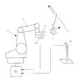
- FIG. 1 is a first configuration example of a robot system including a motion prediction control apparatus according to a first embodiment of the present invention.
- 1 is a workpiece
- 2 is a movable robot
- 3 is a robot arm
- 4 is a hand
- 5a is a first camera fixed to the hand 4
- 5b is a second camera fixed to an external fixed position
- 6 is a fixed landmark
- 10 is a motion prediction control apparatus of the first embodiment.
- the workpiece 1 and the landmark 6 are collectively referred to as an “object”.
- This robot system measures the workpiece 1 moving while pendulum movement and the fixed landmark 6 with the cameras 5a and 5b, measures the robot 2 with the camera 5b, and controls the robot 2 to follow the workpiece 1,
- the workpiece 1 is held by the hand 4.
- the position of the landmark 6 need not be known.
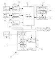
- FIG. 2 is a first configuration example of the motion prediction control apparatus according to the first embodiment of the present invention.
- the motion prediction control device 10 of the first embodiment includes a measurement device 12, a state estimation device 14, a data storage device 16, and a robot control device 20.
- the devices 12, 14 and 20 are connected to the data storage device 16.
- the measuring device 12 measures the relative relationship between the object and the robot 2.
- a measurement result Y such as the relative position or posture between the object and the robot measured by the measurement device 12 is defined as a measurement value Y.
- the measurement value Y is defined according to the type of measurement device and the object to be measured.
- the measured value Y differs depending on the object to be measured (whether it is workpiece 1, landmark 6 or mobile robot 2) and the type of measuring device.
- the relative relationship is information such as position, posture, speed, angular velocity, acceleration, angular acceleration, and the like.
- the measurement device 12 includes three measurement devices (first measurement device 12a, second measurement device 12b, and third measurement device 12c) connected to the first camera 5a, the second camera 5b, and the robot control device 20, respectively. ). That is, in this example, two cameras and two measuring devices are used, the images of the object are taken from the first camera 5a and the second camera 5b, and the measurement value Y of the object is obtained by image processing.
- the measuring device 12b also captures the image of the robot 2 and obtains the measured value Y of the robot 2 by image processing.
- the measuring device 12c measures the amount of movement of the tire of the robot 2 and the amount of rotation of the arm joint with an encoder, and obtains the measured value Y of the robot 2.
- the obtained object and the measured value Y of the robot 2 are stored in the data storage device 16.
- the measuring device 12 is not limited to this configuration, and a device that can measure the relative relationship between the object and the robot 2, such as a laser radar, an acceleration sensor, a gyro sensor, or a speed sensor, may be used.
- the state estimation device 14 is implemented with a state estimation algorithm based on the Kalman filter algorithm.
- the swing angle ⁇ of the pendulum on which the workpiece 1 is suspended ⁇ , fulcrum positions x, y, and z, the positions Xl, Yl, and Zl of the landmark 6, the postures RXl, RYl, RZl, and the position of the robot 2
- State variables such as Xr, Yr, Zr, and postures RXr, RYr, RZr are collectively set as an internal state X.
- An observation equation is defined for each type of measurement value Y. This algorithm manages the error distribution C ov X of the internal state X, the error distribution C ov Y of the measurement value, and the like, and the accuracy of state estimation can be obtained from these data. In the following example, these accuracy index values are collectively referred to as E.
- the state estimation device 14 includes an overall prediction unit 15 a that predicts the internal state of the object and the robot 2, and an update unit 15 b that updates the internal state stored in the data storage device 16. Predict and update internal state.
- the overall prediction unit 15a performs a calculation for causing the internal state X recorded in the data storage device 16 to transition to a designated time using the state transition equation f (X).
- the update unit 15b calculates the predicted value of the measurement value Y of the object and the robot 2 using the internal state X in the data storage device 16 and the observation equation h (X).
- the input measurement value Y and the predicted value are compared, and the internal state X is updated and recorded in the data storage device 16.
- the state estimation accuracy index E is simultaneously updated and recorded in the data storage device 16.
- the measurement device 12, the state estimation device 14, and the data storage device 16 described above are non-real-time processing systems that are executed at a timing different from the control cycle of the robot 2.
- the processing interval of this non-real time processing system may be longer than the control cycle of the robot 2 and the cycle may not be constant. This processing interval is, for example, 30 to 80 ms. Therefore, with the above-described configuration, the measurement device 12, the state estimation device 14, and the data storage device 16 measure the relative relationship (for example, relative position and posture) between the object and the robot at a timing different from the control cycle of the robot 2. Then, the internal state of the object and the robot 2 is predicted and updated, and the updated internal state and the state transition equation used for the prediction are stored.
- the robot control device 20 includes a reception unit 21, a command value calculation unit 22, a transmission unit 23, and an on-robot prediction unit 24.
- the receiving unit 21 receives position information (such as encoder information) from the robot 2.
- the command value calculation unit 22 calculates a command value for the robot 2 from the prediction value obtained by the on-robot prediction unit 24.
- the predicted value is, for example, the current position or future position of the workpiece 1 or the robot 2.
- the transmission unit 23 transmits the calculated command value to the robot 2.
- the on-robot prediction unit 24 predicts a prediction value necessary for controlling the robot 2 at a predetermined control cycle.
- the robot control device 20 includes an on-robot prediction unit 24 that performs a prediction process (prediction) for obtaining a prediction value necessary for controlling the robot 2.
- the on-robot prediction unit 24 only needs to be able to predict the internal quantity (predicted value) related to the control of the robot 2, and does not need to predict all the internal quantities.
- the robot control device 20 transmits an operation command to the robot 2 at a constant cycle (for example, 4 ms) and receives encoder information of the robot 2 and the like.
- the received position information is acquired by the above-described measuring device 12 c and becomes the measurement value Y of the mobile robot 2.
- the on-robot prediction unit 24 is used to predict current and future motion states of the target object and the robot 2 and use them to calculate command values.
- the on-robot prediction unit 24 calculates the state quantity related to the robot control among the internal states X recorded in the data storage device 16 by using the state transition equation f (X) until the specified time. I do.
- the data storage device 16 holds data such as the internal state X, the internal model time tx, the measured value Y, the measured time ty, the state transition equation f, the observation equation h, and the state estimation accuracy index value E. To do.
- the robot control device 20 described above is a real-time processing system controlled by the control cycle of the robot 2.
- This control cycle is a fixed cycle shorter than the processing interval of the non-real time processing system described above.
- This control cycle is, for example, 3 to 4 ms. Therefore, with the above-described configuration, the robot control device 20 predicts a predicted value necessary for the control in the control cycle of the robot 2 based on the latest internal state stored in the data storage device 16, and makes the robot 2 in real time. To control.
- the measuring device 12 measures the object and the robot 2 at an arbitrary timing, and records the measurement result as sensor information in the data storage device 16.
- the state estimation device 14 estimates the internal state by a prediction process and an update process (Collection). The calculated internal state and the state transition equation used for estimation are recorded in the data storage device 16.
- the robot control device 20 controls the robot 2 at a constant control cycle. At this time, the predicted position of the object and the robot 2 at an arbitrary time is calculated using the on-robot prediction unit 24 and used for control.
- the on-robot prediction unit 24 performs a prediction process using the latest internal state or state transition model recorded in the data storage device 16.
- the robot controller 20 operates as a real-time processing system that performs processing at a constant control cycle. Each of the other devices may be a non-real-time processing system that does not have a fixed period time constraint.
- the two measuring devices repeat the following (1) to (3) at an arbitrary timing.
- a shutter signal is transmitted to the cameras 5a and 5b at an arbitrary timing, and a captured image is acquired.
- the position / posture information (measurement value Y) of the object and the robot 2 is acquired from the obtained image by image processing. For example, a white area in the image is extracted and the center of gravity is obtained.
- the calculated measurement value Y, the shutter time (measured value time ty), and the error distribution C ov Y of the measurement value Y are recorded in the data storage device 16.
- the measuring device 12c repeats the following (a1) to (a3) at an arbitrary timing.
- A1 Acquire encoder information of the robot controller 20 at an arbitrary timing.
- A2) The movement amount and joint angle of the tire are obtained from the obtained encoder information, and the position / posture information (measured value Y) of the mobile robot 2 is obtained.
- A3) The calculated measurement value Y, the measurement time of the encoder, and the error distribution C ov Y of the measurement value Y are recorded in the data storage device 16.
- the state estimation device 14 performs the following (4) to (6) every time the measurement value Y is updated.
- the data storage device 16 is monitored, and if a new measurement value Y is recorded, Y, ty, X, tx, f, h, E are read from the data storage device 16.
- the internal state X indicates the internal state at the time tx
- the internal state at the time ty is predicted using the overall prediction unit 15a.
- (6) Using the update unit 15b, the measured value at the time ty is predicted, the predicted value and the measured value Y are compared, and the internal state X is corrected.
- the update unit 15 b calculates an error distribution C ov X of the internal state X and an accuracy index E such as a difference between the measured value and the predicted value, and records it in the data storage device 16.
- the robot controller 20 repeats the following (7) to (10) at an arbitrary cycle.
- Communication with the robot 2 is managed by the robot 2 so as to be performed, for example, at a cycle of 4 ms. Therefore, the robot control unit 20 must wait until data is received, and complete the transmission process (11) within 4 ms after receiving the data.
- the current position of the workpiece and the robot and the future position are calculated using the robot prediction unit 24. When performing this calculation, the on-robot prediction unit 24 refers to the latest internal state or the like in the data storage device 16. (9) A target trajectory is calculated so that the arm hand approaches the predicted position of the workpiece 1.
- the arm target trajectory and the hand opening / closing command value are calculated so that the gripping operation is performed to the position of the future workpiece. . (10)
- the calculated target trajectory and hand opening / closing command value are transmitted to the robot 2.
- FIG. 3 is a second configuration example of the motion prediction control apparatus according to the first embodiment of the present invention. This example is suitable when the time required for communication between the robot control device 20 and the data storage device 16 is long. That is, in this example, the data storage device 16 has a function of transferring the latest internal state stored in the data storage device 16 to the robot storage unit 26 at a timing that does not depend on the request from the robot 2.
- the data storage device 16 transfers the internal state and state transition model recorded in the data storage device 16 to the on-robot storage unit 26.
- the on-robot prediction unit 24 performs processing with reference to data stored in the on-robot storage unit 26.
- the transfer timing may be when the internal state X of the data storage device 16 is updated (immediately after (6)). Data transfer is performed when it is detected that new data has been recorded in the data storage device 16 (immediately after (6)) or at regular intervals. Alternatively, it may be performed at both timings described above.
- the contents of the data storage device 16 are sequentially transferred to the on-robot storage unit 26, and the on-robot prediction unit 24 refers to the on-robot storage unit 26. Therefore, it is necessary to communicate in the calculation of (8) described above. There is no. Therefore, even when communication using a long communication time such as wireless communication is used, the influence of communication time can be avoided.
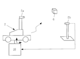
- FIG. 4 is a second configuration example of the robot system including the motion prediction control apparatus according to the first embodiment.
- This example is different from the first configuration example of the robot system in that the robot 2 is fixed and there is no landmark 6.
- Other configurations are the same as those of the first configuration example. That is, this example is a case in which the workpiece 1 moving with the arm 3 of the fixed robot 2 is gripped, and is different from the first configuration example of the robot system in that it is not necessary to estimate the robot 2.
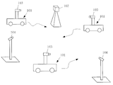
- FIG. 5 is a third configuration example of the robot system including the motion prediction control device according to the first embodiment.
- This example is a case in which the robot 2 estimates its own position from the landmark 6 whose position is known, and the first configuration example is that it is not necessary to estimate the workpiece and the position and orientation of the landmark 6. And different.
- the mobile robot 2 measures the landmark 6 whose position is known, and estimates the self-position of the robot 2.
- the estimated internal quantity X is the origin position (X r , Y r , Z r ) of the robot 2 and the posture (R xr , R yr , R zr ) of the robot 2.
- the steer angle, speed, angular velocity, etc. of the wheel may be estimated.
- the wheel rotation amount ( ⁇ ) recorded by the robot controller 20 as a result of measuring the landmark 6 by the camera 5a, the position of the robot 2 by the camera 5b, or the like is used.
- the other points may be the same as those of the first configuration example of the robot system.
- the first embodiment of the present invention is not limited to the configuration example described above.
- it is a combination of workpiece motion state estimation and robot motion state estimation, so the first embodiment described above realizes a system that takes into account the time constraints of robot control. it can.
- the pendulum work and the wheel-type mobile robot are shown.
- the form in which each moves is not limited thereto.
- the workpiece may be one that moves on a conveyor, one that floats on water, or one that is flying.
- the robot may be a crawler type or a type that moves on a rail.
- “moving” includes cases in which the base sways or passively moves even with a fixed arm.
- each device need not be separated into separate processing devices.
- a configuration in which a plurality of programs are processed in parallel on one PC may be used as the measurement program and the state estimation program.
- the robot control device is a real-time processing system that performs processing under the constraint of a fixed period.
- a non-real-time processing program and a real-time processing program can be paralleled.
- the data storage device 16 may be a shared memory in which a plurality of devices and programs read and write the same data. Therefore, it is not necessary to use an independent device, and it is sufficient that the device is prepared in a memory space such as the state estimation device 14 or the measurement device 12.
- the measurement device 12, the state estimation device 14, and the data storage device 16 measure the relative relationship (for example, relative position) between the object and the robot, Predicts and updates the internal state between robots and stores the updated internal state and the state transition equation used for the prediction, so the measurement results (for example, position and orientation) of the object (work or landmark) and the robot ) To predict the motion of the moving body (work or mobile robot).
- the robot control device 20 has an on-robot prediction unit 24 that predicts a predicted value necessary for controlling the robot 2 in the control cycle of the robot 2, and the latest internal state stored in the data storage device 16 is updated. Based on this, the predicted value is predicted in the control cycle, and the robot 2 is controlled in real time. Therefore, the control command value is calculated in the control cycle determined for each robot without being affected by the calculation amount of the state estimation. The robot 2 can be controlled.
- the robot controller 20 can operate without being affected by the time required for the state estimation update process. Even when the number of measuring devices 12 and robot control devices 20 increases and the amount of calculation for state estimation increases, the time required for the prediction process does not increase because each robot control device 20 performs prediction calculation independently. Therefore, it is not necessary to review the design of arithmetic processing capacity when the system is changed. Furthermore, the time constraint of the prediction process can be set for each robot control device 20. Also, the accuracy of the predicted value to be calculated, the type of predicted value, and the like can be set for each robot control device 20. Therefore, in consideration of the time required for the prediction process, the control period, and the like, the respective robots 2 can realize contrivances such as changing the accuracy of the prediction calculation or calculating only necessary variables in the internal state.
- the data storage device 16 transfers the latest internal state stored in the data storage device 16 to the on-robot storage unit 26 at a timing that does not depend on the request from the robot 2, so that the robot controller 20 and the state estimation are performed. Even when the communication between the devices 14 takes a long time or when the required communication time is not constant, the data necessary for the prediction process can be referred to immediately. In this case, the data referred to on the robot 2 does not necessarily become the latest value due to the influence of communication delay, but the prediction process can be completed within a certain time.
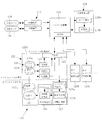
- FIG. 6 is a schematic diagram of a robot system including a motion prediction control apparatus according to the second embodiment of the present invention.
- 101 is a mobile robot
- 102 is a landmark fixed to the outside of the mobile robot 101
- 103 is an internal sensor fixed to the mobile robot 101
- 104 is an external sensor fixed to the outside of the mobile robot 101.
- a plurality of mobile robots 101 can move autonomously.
- the mobile robot is simply referred to as “robot”.
- FIG. 7 is a first configuration example of a motion prediction control apparatus according to the second embodiment of the present invention.
- the motion prediction control device 110 of the second embodiment includes a measurement device 112, a state estimation device 114, a data storage device 116, and a plurality of robot control devices 120.
- Devices 112, 114, 120 are each directly connected to data storage device 116.
- the plurality of robot control devices 120 include a first robot control device 120A, a second robot control device 120B, and a third robot control device 120C.
- the number of robot control devices 120 is three, but may be two or four or more.
- the measuring device 112 is connected to the corresponding external sensor 104 and takes in sensor information (observed values) of the external sensor 104.
- the external sensor 104 include a camera, a laser range finder (LRF), a three-dimensional laser radar, a gyro sensor, a GPS compass, and a pulse encoder.
- the measurement device 112 reads sensor information from the external sensor 104 at an arbitrary timing, and performs measurement processing (operations (1) to (3)) described later.
- the measurement unit 124 on the robot control device 120 has the same function as the measurement device 112.
- the configuration of the robot control device 120 described later that does not have a moving mechanism or a processing unit for drive control is referred to as a “measurement device 112”.
- the state estimation device 114 is implemented with a state estimation algorithm based on the Kalman filter algorithm.
- state variables such as the position x, y, z, velocity vx, vy, vz, angular velocity drx, dry, drz of the robot 101 are collectively defined as an internal state X.
- a state transition equation X (t + ⁇ t) f (X (t)) indicating how the internal state X changes with time
- an observation equation Y h that associates the internal state X with the observed value Y.
- (X) An observation equation is defined for each type of observation value Y (sensor information).
- this algorithm and the error distribution C ov X of internal state X, manages and error distribution C ov Y observations Y, can be determined the accuracy of the state estimation from these data.
- these accuracy index values are collectively referred to as E.
- the state estimation device 114 is provided with two functions of an overall prediction unit 115a and an update unit 115b.
- the overall prediction unit 115a performs a calculation of causing the internal state X recorded in the data storage device 116 to transition to a designated time using the state transition equation f (X).
- the update unit 115b uses the overall prediction unit 115a to transition to the measurement time and uses the observation equation h (X) and the predicted value of the observed value Y of the target (robot 101 or landmark 102). Is calculated.
- the input observed value Y and the predicted value are compared, and the internal state X is updated and recorded in the data storage device 116.
- the state estimation accuracy index value E is also updated and recorded in the data storage device 116.
- the robot control device 120 in FIG. 7 shows a configuration used in a general robot 101.
- a robot control device 120 performs a sensor process of a driving unit 121 for movement, a vehicle control unit 122 that controls the driving unit 121, an action planning unit 123 that calculates a target trajectory of the robot 101, and each sensor 103.
- the measuring unit 124 is configured.
- the sensors 103 are mainly used for measuring the angular velocity or acceleration of the robot 101, the distance measuring sensor 103b (LRF) for measuring the surrounding shape, and the amount of rotation of the wheels provided in the robot 101. This is the wheel encoder 103c.
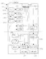
- FIG. 8 is a second configuration example of the motion prediction control apparatus according to the second embodiment of the present invention.
- the type of the sensor 103 is not limited. That is, for example, as shown in FIG. 8, sensors such as a camera 103d, a GPS compass 103e, and a steering angle encoder 103f for measuring the steering angle of wheels provided in the robot 101 may be added, or some sensors may be used. There may be no configuration.
- other points may be the same as those of the first configuration example of the motion prediction control apparatus.
- the action planning unit 123 is a real-time processing system that operates at a constant control cycle, and predicts the current or future position or posture of the robot 101 using the on-robot prediction unit 123a. It is used for calculation of the target trajectory of the robot 101 by the trajectory generation unit 123b. Moreover, the present or future position or posture of the other robot 101 is predicted as necessary, such as in the case of collision avoidance.
- the on-robot prediction unit 123a performs a calculation for transitioning a state quantity related to robot control from the internal state X recorded in the data storage device 116 to a specified time using the state transition equation f (X). I do.
- the on-robot prediction unit 123a is designed to perform prediction processing under the time constraint of real-time control.
- the vehicle control unit 122 is a real-time processing system that operates at a constant control cycle, and controls the drive unit 121 by calculating a command value using the command value calculation unit 122a so that the robot 101 moves along the target trajectory.
- the communication unit 125 has a data communication function between the robot 101 (that is, the robot control device 120 provided in the robot 101) and the data storage device 116. Specifically, a device that performs wired communication such as Ethernet (registered trademark) or USB, or wireless communication such as Bluetooth (registered trademark) or wireless LAN is used.
- wired communication such as Ethernet (registered trademark) or USB
- wireless communication such as Bluetooth (registered trademark) or wireless LAN is used.
- the data storage device 116 holds data such as the internal state X, the model time tx of the internal state, the observed value Y, the measured time ty, the state transition equation f, the observation equation h, and the state estimation accuracy index value E.
- the measuring device 112 or the measuring unit 124 repeats the following (1) to (3) at an arbitrary timing.
- Acquire sensor information at an arbitrary timing For example, in the case of a camera, a shutter signal is transmitted to the camera, and a captured image is acquired.
- the acquired sensor information is processed, and an observed value Y such as the position and posture of the robot 101 or the landmark 102 and the speed or angular velocity of the robot 101 is obtained. Since the observed value Y differs for each sensor, it is defined for each sensor.
- the sensor information processing performed here also differs depending on the type of sensor.
- sensor information on the position and orientation of an object is acquired from the obtained image by image processing (eg, a white area in the image is extracted to obtain the center of gravity).
- image processing e.g, a white area in the image is extracted to obtain the center of gravity.
- a pulse wave counting process or the like can be considered.
- the calculated observed value Y, the measured time ty (such as shutter time), and the error distribution C ov Y of the observed value Y are recorded in the data storage device 116.
- the state estimation device 114 performs the following (4) to (6) every time the observed value Y is updated.
- the data storage device 116 is monitored, and if a new observed value Y is recorded, Y, ty, X, tx, f, h, E are read from the data storage device 116.
- the observed value at the time ty is predicted from the internal state predicted in (5), and the predicted value and the observed value Y are compared to correct (update) the internal state X. .
- the updating unit 115 b calculates an accuracy distribution value E such as the error distribution C ov X of the internal state X and the magnitude of the difference between the observed value and the predicted value, and records it in the data storage device 116.
- the action planning unit 123 on the robot control device 120 repeats the following (7) to (8) at a constant cycle.
- the current position and future position of the robot 101 are calculated using the robot prediction unit 123a. Further, the current position and future position of the other robot 101 are calculated as necessary for collision avoidance and the like.
- a target trajectory is generated so that the robot 101 moves to the target position.
- the vehicle control unit 122 on the robot control device 120 repeats the following (9) to (11) at a constant cycle.
- the current speed of the robot 101 is obtained from the wheel encoder 103c.
- a control command value that moves along the target trajectory generated by the action planning unit 123 is calculated.
- the calculated control command value is transmitted to the drive unit 121.
- the vehicle control unit 122 needs to calculate a control command value at a constant period. Further, the target trajectory referred to by the vehicle control unit 122 needs to be generated in advance by the action planning unit 123. Therefore, the process of the action plan part 123 and the vehicle control part 122 is a real-time process repeated with a fixed period.
- the control cycle of the action planning unit 123 is longer than the control cycle of the vehicle control unit 122 (depending on the length of the target trajectory generated at one time).
- the target trajectory includes a rough movement route to the target point in addition to the latest movement route referred to by the vehicle control unit 122. Therefore, the action planning unit 123 may be further divided into two or more processes such as local route generation, global route generation, and global route generation. In this case, the process of generating a local route is a shorter control cycle.
- the global region may be a long control cycle or non-real-time processing in which the cycle is not constant.
- FIG. 9 is a third configuration example of the motion prediction control apparatus according to the second embodiment of the present invention.
- the robot control device 120 further includes an on-robot storage unit 126.
- the on-robot prediction unit 123a refers to the latest internal state X in the data storage device 116.
- the predicted value may not be obtained under a certain time constraint. Therefore, in this example, the contents of the data storage device 116 are sequentially transferred to the on-robot storage unit 126, and the on-robot prediction unit 123a refers to the on-robot storage unit 126.
- the transfer timing is when the internal state X of the data storage device 116 is updated (immediately after (6) described above).
- the second robot control device 120B and the third robot control device 120C also include an on-robot prediction unit 123a, an on-robot storage unit 126, and the like.
- the number of robot control devices 120 is three, but may be two or four or more.
- other points may be the same as those of the first configuration example or the second configuration example of the motion prediction control apparatus.
- FIG. 10 is a fourth configuration example of the motion prediction control apparatus according to the second embodiment of the present invention.
- the expression “measuring device 112” is used for explanation, but the measuring device 112 is provided in the robot control device 120 (that is, the robot 101) that does not have a moving mechanism. Treat as a kind. Therefore, it is assumed that the system configuration in the second embodiment of the present invention includes two types of state estimation device 114 and robot control device 120, and robot control device 120 (robot 101) includes one that does not have a moving mechanism.
- the data storage device 116 may be a shared memory in which a plurality of devices and programs read and write the same data.
- the state estimation device 114 may be installed on any of the robots 101 and integrated with the robot control device 120 as shown in FIG.
- a plurality of programs can be processed in parallel on one PC as a state estimation program and a robot control program.
- other points may be the same as those of the first configuration example, the second configuration example, or the third configuration example of the motion prediction control apparatus.
- the predicted value calculated by the on-robot prediction unit 123a is used for the control of the robot 101.
- the robot 101 measures surrounding people and objects, and the information on the position and motion is detected by the on-robot prediction unit 123a. It can also be used for services that present information that changes in real time, such as predicting and presenting to people.
- the measurement device 112, the state estimation device 114, and the data storage device 116 can be used to detect an object or a plurality of objects at an arbitrary timing that does not depend on the control cycle of the robot 101.
- the sensor information of the robot 101 is acquired, the internal state X of each robot 101 at the same time as the time when the sensor information is acquired is predicted, the predicted internal state is updated by comparing with the sensor information, and the updated internal state Since X and the state transition equation f (X) used for the prediction are stored, the motion prediction of each robot 101 is performed based on the object (for example, the landmark 102) and the sensor information (for example, the position and orientation) of the robot 101. Can do.
- the plurality of robot control devices 120 predict the predicted value required for each robot 101 based on the latest internal state X stored in the data storage device 116, it is not affected by the calculation amount of the state estimation. It is possible to control a plurality of robots 101 by calculating a control command value at a control cycle determined for each robot 101.
- each robot control device 120 can operate without being affected by the time required for the state estimation update process. Also, when the number of measuring devices 112 and robot control devices 120 increases and the amount of calculation for state estimation increases, the time required for the prediction process does not increase because each robot control device 120 performs prediction calculation independently. Therefore, it is not necessary to review the design of arithmetic processing capacity when the system is changed. Furthermore, the time constraint of the prediction process can be set for each robot control device 120. In addition, the accuracy of the predicted value to be calculated, the type of predicted value, and the like can be set for each robot control device 120. Therefore, each robot 101 can realize a device such as changing the accuracy of prediction calculation or calculating only necessary variables in the internal state X in consideration of the time required for the prediction process, the control cycle, and the like.
- the data storage device 116 transfers the latest internal state X stored in the data storage device 116 to the on-robot storage unit 126 at a timing that does not depend on the request from the robot 101, so that the state of the robot control device 120 Even when the communication between the estimation devices 114 takes a long time or when the required communication time is not constant, the data necessary for the prediction process can be referred to immediately. In this case, the data referred on the robot does not necessarily become the latest value due to the influence of communication delay, but the prediction process can be completed within a certain time.
- the second embodiment of the present invention is not limited to the above-described configuration example, is shown by the description of the scope of claims, and further includes meanings equivalent to the description of the scope of claims and all modifications within the scope. It is a waste.
- FIG. 11 is a configuration example of a robot system having a motion prediction control apparatus according to the third embodiment of the present invention.
- 201 is an object (work)
- 202 is a robot
- 203 is a robot arm
- 204 is a hand
- 205a is a first camera fixed to the hand 204
- 205b is a second camera fixed to an external fixed position.
- 210 is a motion prediction control device.
- a workpiece 201 that moves while moving in a pendulum is measured by cameras 205 a and 205 b
- the robot 202 is controlled to follow the workpiece 201
- the workpiece 201 is gripped by the hand 204.
- FIG. 12 is a configuration example of a motion prediction control apparatus according to the third embodiment of the present invention.
- the motion prediction control device 210 includes a measurement device 212, a state estimation device 214, and a robot control device 220.
- the state estimation device 214 includes a data storage device 216.
- the measuring device 212 measures the position and orientation of the object 201.
- the measurement device 212 includes two measurement devices (a first measurement device 212a and a second measurement device 212b) connected to the first camera 205a and the second camera 205b, respectively.
- two cameras and two measuring devices are used, images of the object 201 are captured from the first camera 205a and the second camera 205b, and the position and orientation of the object 201 are obtained by image processing.
- the obtained position and orientation of the object 201 are stored in the data storage device 216.
- the measurement device 212 is not limited to this configuration, and a measurement device capable of three-dimensionally measuring the position of the object 201, for example, a laser radar may be used.
- the state estimation device 214 estimates (updates) the internal state of the object 201 including the accuracy index value E (described later) from the measurement result obtained by measuring the object 201 based on the state transition model and the observation model, and It has a function of determining whether or not the object 201 can be gripped from the accuracy index value E.
- a state estimation algorithm based on the Kalman filter algorithm is implemented in the state estimation device 214.
- the following four are defined as “state transition models”.
- Internal state at time t 0: X 0
- Covariance of initial condition X 0 C ov X 0
- State transition equation: X t + ⁇ t f (X t , ⁇ t) (1)
- state variables such as the swing angle ⁇ , the angular velocity ⁇ , and the fulcrum positions x, y, and z of the pendulum on which the object 201 is suspended are collectively defined as an internal state X.
- a covariance C ov X 0 is defined that predicts how large the difference between the initial condition and the actual one will be.
- the state transition equation (1) shows how the internal state X changes with time. In the case of this example, the state transition equation is defined from the equation of motion of the pendulum and the fact that the fulcrum position moves at a constant linear velocity.
- the Kalman filter defines the “observation model” (observation equation and observation noise) of equations (2) and (3) with the position and orientation of the object 201 calculated by the measurement device 212 as the measurement value Y.
- Observation equation: Y t g (X t ) (2)
- Observation equation (2) is an equation that associates the internal state X with the measured value Y.
- the observation noise (3) is a covariance representing how much measurement error is included in the measurement at time t, and is determined by the resolution of the camera and the orientation of the viewpoint.
- the observation noise (3) is not a fixed value, but is calculated by the measurement device 212 for each image and is passed to the state estimation device 214 together with the measurement value.
- the robot control device 220 has a function of controlling the robot 202 so as to perform a gripping operation by predicting the movement destination of the object 201 based on the estimation result (update result) of the internal state when it can be gripped.
- Robot control device 220 receives hand position information from robot 202 and transmits hand speed command values and hand opening / closing command values. These transmission and reception are performed at a constant control cycle (4 ms cycle).
- the measurement device 212 measures the position and orientation of the object 201 as sensor information.
- the state estimation device 214 estimates (updates) the internal state of the object 201 including the accuracy index value E based on the state transition model, and (C) the accuracy index value. Whether or not the object 201 can be gripped is determined from E.
- the robot controller 220 predicts the movement destination of the object 201 based on the estimation result of the internal state and causes the robot 202 to perform a gripping operation.
- the robot 202 is moved by the robot controller 220 so that the measurement of the position and orientation of the object 201 can be continued.
- the accuracy index value E includes an error between a predicted value obtained by predicting the position and orientation of the object 201 and an actual measurement value thereof, and a covariance matrix that predicts the variance of the error based on the state transition model and the observation model.
- the first threshold value and the second threshold value are arbitrary threshold values set in advance.
- the error less than a square third threshold Mahalanobis distance M t divided by the covariance matrix and, when the trace of the covariance matrix is less than the fourth threshold value, determines that the graspable May be.
- the third threshold value and the fourth threshold value are arbitrary threshold values set in advance.
- the measurement device 212 (the first measurement device 212a and the second measurement device 212b) transmits a shutter signal to each of the two cameras (the first camera 205a and the second camera 205b) at an arbitrary timing, and is imaged. Get an image.
- Information (measurement value Y) of the position and orientation of the object 201 is acquired from the obtained image by image processing by the measurement device 212. For example, a white area in the image is extracted and the center of gravity is obtained.
- the time when the shutter signal is transmitted from the measuring device 212 is ty.
- the state estimation device 214 corrects the internal state X by comparing the measured value Y with the predicted value Ym of Y predicted by the state transition model and the observation model. Also, an accuracy index value E representing the accuracy of predicting the position of the object 201 is calculated. The internal state is updated at an arbitrary timing that does not depend on the control cycle of the robot controller 220.
- the robot control device 220 refers to the result of the state estimation device 214 for each control cycle, evaluates the accuracy index value E, and determines whether to start the gripping operation.
- a time width ⁇ t for state transition is calculated from the measurement time ty and the current model time t.
- the initial value of the model time t is the time when measurement is started. Further, the measurement time may be defined as an elapsed time with the start time as a base point, and the initial value of the model time may be set to zero.
- K t + ⁇ t (C ov X t + ⁇ t
- the internal state is corrected (that is, updated) based on the observed value at time ty.
- the internal state is updated at an arbitrary timing that does not depend on the control cycle of the robot controller 220. Therefore, as the entire system repeats the processes (a1) to (a6), the internal state gradually approaches a true value (actual speed of the object, etc.).
- the state estimation device 214 calculates an accuracy index value E representing the accuracy of the current state estimation as follows after the processing from (b1) to (b9).
- the accuracy index value E is calculated by any of the following (c1), (c2), and (c3).
- equation (16) in (c1) is an evaluation equation for model fitness of a normal distribution
- equation (18) in (c3) is an information criterion (AIC).
- Expression (17) of (c2) is characterized in that a covariance C ov Y trace is used as the denominator.
- the square root of the covariance determinant represents the volume of the distribution of eY.
- the square root of the trace represents the radius of the smallest sphere that wraps around the distribution.
- FIG. 13 is an overall flowchart of the motion prediction control method according to the third embodiment of the present invention. As shown in this figure, the motion prediction control method includes steps (steps) S1 to S12.
- hand position information is received from the robot 202.
- the communication with the robot 202 is managed by the robot 202 so as to be performed, for example, with a control period of 4 ms. Therefore, the robot controller 220 must wait until data is received, and complete the transmission process of S12 within a control period of, for example, 4 ms after receiving the data.
- a flag F indicating that the gripping operation is being performed is determined. The flag F is initialized to false at the start of the program.
- the determination means uses any of the following (d1) to (d3).
- the object 201 is out of the field of view of one camera and measurement is continued with only one camera.
- the covariances C ov Y and V are covariance matrices indicating a long and narrow distribution in the viewing direction of the camera.
- the gripping operation may be started.
- Vx Kpx ⁇ (mx ⁇ rx) + Kdx ⁇ (mx ⁇ rx ⁇ pr_x) (19)
- Vy Kpy ⁇ (my ⁇ ry) + Kdy ⁇ (my ⁇ ry ⁇ pr_y) (20)
- Vz Kpz ⁇ (mz ⁇ rz) + Kdz ⁇ (mz ⁇ rz ⁇ pr_z) (21)
- This control is PD control, where mx, my, and mz are the current position [mm] of the measured object, and rx, ry, and rz are the current position [mm on the camera's line of sight] [mm]. ], Pr_x, pr_y, pr_z are position deviations (my-ry, mz-rz, etc.) calculated in the previous step, Kp is a position control gain, and Kd is a differential control gain.
- the gripping operation flag F is set to true when the gripping operation is started.
- the target speed of the robot arm 203 is calculated so that the robot arm 203 moves to the gripping position A during the gripping operation.
- the gripping operation flag F is set to false. When the gripping operation is not terminated, the gripping operation flag F remains true, so that the gripping operation is continued from the next time due to the branch of S2.
- the calculated target speed and hand opening / closing command value are transmitted to the robot 202.
- the Kalman filter is used as a method for estimating the motion state of the object 201.
- any other method may be used as long as it is a state estimation method that satisfies the following conditions.
- a particle filter or a least square method can be applied.
- the future state can be predicted by estimating the motion state of the object 201.
- E2 A covariance matrix representing the variance of the prediction error when a future position is predicted can be calculated.
- FIG. 14 is a diagram illustrating the relationship between the elapsed time and the accuracy index value E in the embodiment. This example is a result of calculating the accuracy index value E by the above-described equation (17) of (c2).
- the accuracy index value E gradually increases from the start of measurement, and stabilizes at 80 or more after 2 seconds from the start of measurement. Therefore, it can be said that the gripping failure is unlikely to occur when the gripping operation start condition is that the accuracy index value E of Expression (17) is 80 or more.
- the accuracy index value may temporarily increase as seen in the elapsed time around 1 second. Therefore, as in (c3) described above, it is preferable to make a determination in consideration of accuracy index values for the past several points.
- the average value of past several points exceeds 80, or exceeds 80 continuously for a certain time.
- the accuracy index value exceeds 80 continuously for 120 ms or longer” may be set as the gripping operation start condition.
- the measurement apparatus 212 and the state estimation apparatus 214 measure the position or orientation of the object 201 and estimate the internal state of the object 201. Even if it is a motion other than a fast linear motion, a uniform circular motion, and a uniform acceleration linear motion, the motion of the target 201 is predicted based on the internal state (for example, position, posture, speed, angular velocity) of the target 201 (for example, a workpiece). can do.
- the internal state for example, position, posture, speed, angular velocity
- the state estimation device 214 estimates the internal state of the object 201 including the accuracy index value E based on the state transition model and the observation model, and determines whether or not the object 201 can be gripped from the accuracy index value E.
- the robot controller 220 moves the robot 202 so that measurement of the position and orientation of the object 201 can be continued, for example, so that gripping failure can be avoided even when the prediction accuracy decreases. be able to.
- the robot controller 220 predicts the movement destination of the target object 201 based on the estimation result of the internal state and grips the robot 202. Therefore, the robot 202 is made to follow the target object 201. It can be securely gripped.
- the object 201 is moved and the robot 202 is fixed.
- the third embodiment of the present invention is not limited to this example, and the object is moved even when the robot moves without moving the object. And both robots may move. Therefore, “movement of the object” in the third embodiment of the present invention means relative movement of the object as viewed from the robot.
- the third embodiment of the present invention is not limited to the above-described configuration example, is shown by the description of the scope of claims, and further includes all modifications within the meaning and scope equivalent to the description of the scope of claims. It is a waste.
Abstract
(A) Sensor information is acquired by measuring one or both of a target object and a robot (2) with measuring devices (12a, 12b). (B) The internal states of one or both of the target object and the robot (2) are predicted and updated by a state-estimating device (14) based on the sensor information. (C) The internal states are stored using a data storage device (16). (D) The robot (2) is controlled by a robot control device (20). In (B), the internal states are updated by the state-estimating device (14) with a chosen timing that does not depend on the robot control cycle. In (D), the prediction value necessary for control of the robot is calculated by the robot control device with the periodicity of the control cycle based on the most recent internal states stored in the data storage device (16).
Description
本発明は、ロボットなどを使った自動装置のうち、ワークやロボットなどの運動を予測する運動予測制御装置と方法に関する。
The present invention relates to a motion prediction control apparatus and method for predicting the motion of a workpiece, a robot, etc., among automatic devices using a robot or the like.
(ロボットの位置を計測してロボットを制御する場合)
ロボット上やロボットの外部に設置したセンサ情報を使って、ロボットの位置や姿勢を算出し、ロボットを駆動制御する制御装置において、ロボットの位置と姿勢の計測に使われるセンサや計測方法としては、以下が一般的である。
(1) ロボット上の内界センサを使う方法。
例えば、ロボット上に設置したジャイロセンサや車輪のエンコーダなどで、ロボットの速度、加速度、角速度などを計測する。ロボット上に設置したステアリング部のエンコーダなどで、ロボットのステア角を計測する。
(2) ロボット上の外界センサを使う方法。
例えば、ロボット上に設置した測距センサ(レーザーレンジファインダ(LRF)、レーザレーダなど)やカメラなどで、ロボット周囲のランドマークの位置や姿勢を計測する。ロボット上に設置したGPSコンパスなどで、ロボットの現在の位置と姿勢の一方又は両方を計測する。
(3) ロボット外の外部センサで計測する方法。
ロボット外部に設置した測距センサやカメラなどで、計測範囲内のロボットの位置や姿勢を計測する。 (When controlling the robot by measuring the robot position)
Sensors and measurement methods used to measure the robot's position and orientation in a control device that calculates and controls the robot's position and orientation using sensor information installed on and outside the robot. The following is common.
(1) A method using an internal sensor on the robot.
For example, the speed, acceleration, angular velocity, etc. of the robot are measured with a gyro sensor or wheel encoder installed on the robot. The steer angle of the robot is measured with the encoder of the steering unit installed on the robot.
(2) Using an external sensor on the robot.
For example, the position and orientation of landmarks around the robot are measured by a distance measuring sensor (laser range finder (LRF), laser radar, etc.) or a camera installed on the robot. One or both of the current position and posture of the robot are measured with a GPS compass installed on the robot.
(3) A method of measuring with an external sensor outside the robot.
The position and orientation of the robot within the measurement range are measured with a distance measuring sensor or camera installed outside the robot.
単一のセンサでロボットの位置や姿勢を精度よく求めることは困難なため、上述のセンサや計測方法を複数用いて、得られた複数の計測結果から位置や姿勢を求めることがある。
しかし、以下のような理由で、複数の計測結果を簡単に比較することはできない。
(2)(3)で計測される位置と姿勢は、計測するセンサや、特定の点を基点とする座標系で表される相対的な位置と姿勢である。計測座標の基点はそれぞれ異なる上に、ロボット上のセンサの場合は、基点となるロボット自身の位置が不明なため、単純に座標変換等で、これらの計測結果を比較することは難しい。
(1)は、位置や姿勢を直接計測するものではないため、(2)(3)と直接比較できない。 Since it is difficult to accurately determine the position and orientation of the robot with a single sensor, the position and orientation may be obtained from a plurality of obtained measurement results using a plurality of the above-described sensors and measurement methods.
However, a plurality of measurement results cannot be easily compared for the following reasons.
(2) The position and orientation measured in (3) are a relative position and orientation represented by a sensor to be measured and a coordinate system based on a specific point. The base points of the measurement coordinates are different from one another, and in the case of a sensor on the robot, the position of the robot itself as the base point is unknown, so it is difficult to compare these measurement results simply by coordinate transformation or the like.
Since (1) does not directly measure the position or orientation, it cannot be directly compared with (2) or (3).
また、以下で述べるように、全てのセンサ情報を同期して計測することは困難である。したがって、得られた計測結果の計測時刻は、それぞれ異なる場合がある。ロボットの位置と姿勢は時々刻々と変化するため、時刻の揃っていない計測結果を単純に比較することはできない。特にロボットの速度が速い場合などでは、位置と姿勢の変化量が大きいため、このような問題が起こりやすい。
Also, as described below, it is difficult to measure all sensor information synchronously. Therefore, the measurement times of the obtained measurement results may be different. Since the position and posture of the robot change from moment to moment, it is not possible to simply compare measurement results that do not have the same time. In particular, when the robot speed is high, the amount of change in position and orientation is large, and such a problem is likely to occur.
a 一般的に、同一ロボット内の内界センサのセンサ情報は同期して取得される。しかし、例えば、異なるロボット間で、1つの同期信号を共有するのは難しい(有線接続が必要)。したがって、複数のロボット間で内界センサの情報を同期するのは困難である。
b (3)のように外部センサを用いる場合も、aと同様に、複数の装置間で同期信号を授受する必要がある場合には、外部センサとロボット上のセンサの同期は困難である。
c (2)や(3)で使われるセンサには、センサそのものの計測時間や、センサから得られたセンサ情報を処理する時間などによる計測遅れがある。したがって、センサで得られる計測結果は、計測遅れの分古いセンサ情報となるため、(1)のような内界センサのセンサ情報と計測時刻が異なる。また、計測対象がセンサの視野から外れる場合があるため、指定した時刻の計測結果が常に得られるとは限らない。 a In general, sensor information of internal sensors in the same robot is acquired synchronously. However, for example, it is difficult to share one synchronization signal between different robots (requires a wired connection). Therefore, it is difficult to synchronize the information of the internal sensor between a plurality of robots.
b When using an external sensor as in (3), it is difficult to synchronize the external sensor and the sensor on the robot when a synchronization signal needs to be exchanged between a plurality of devices, as in a.
c The sensors used in (2) and (3) have a measurement delay due to the measurement time of the sensor itself, the time to process sensor information obtained from the sensor, and the like. Therefore, since the measurement result obtained by the sensor becomes sensor information that is old due to the measurement delay, the sensor information of the internal sensor as in (1) is different from the measurement time. Further, since the measurement target may be out of the field of view of the sensor, the measurement result at the designated time is not always obtained.
(移動するワークをハンドリングする場合)
移動するワークをロボットでハンドリングする自動装置では、ロボット上やロボットの外部に設置したカメラなどの視覚センサやレーザーレンジファインダ(LRF)などの測距センサでワークの位置を計測し、その計測結果に基づいてロボットアームを追従制御させる必要がある。
ロボット自身が移動する移動ロボットの場合でも、ロボット上やロボットの外部に設置したセンサで移動ロボットの位置を計測し、計測結果に基づいてロボットを制御する必要があり、同様の技術が用いられる。ロボットの位置を計測する方法には、上述のように、ロボット上のセンサでランドマークとの相対位置を計測する方法や、ロボットの外部に設置したセンサでロボットの位置を直接計測する方法がある。
以下、移動するワークや移動ロボットを単に「移動体」とも呼ぶ。 (When handling moving workpieces)
In an automatic device that handles a moving workpiece with a robot, the position of the workpiece is measured by a visual sensor such as a camera installed on the robot or outside the robot, or a distance measuring sensor such as a laser range finder (LRF). Based on this, it is necessary to control the robot arm to follow up.
Even in the case of a mobile robot in which the robot itself moves, it is necessary to measure the position of the mobile robot with a sensor installed on the robot or outside the robot and control the robot based on the measurement result, and the same technique is used. As described above, the method for measuring the position of the robot includes a method for measuring the relative position to the landmark with a sensor on the robot and a method for directly measuring the position of the robot with a sensor installed outside the robot. .
Hereinafter, the moving workpiece and the moving robot are also simply referred to as “moving body”.
上述したロボットの運動予測制御では、時々刻々と変化する対象物(ワークやランドマーク)やロボット間の相対位置を一定周期(例:30fpsのカメラ)で計測し、計測結果に基づいて、例えばワークにロボットを近づけるような、移動指令がロボットに出力される。
In the robot motion prediction control described above, the object (work or landmark) that changes from moment to moment and the relative position between the robots are measured at a constant period (eg, 30 fps camera), and based on the measurement result, for example, the workpiece A movement command is output to the robot to bring the robot closer to the robot.
しかし、計測したワークの位置を目標としてロボットを動作させても、センサの計測遅れ、データの取得遅れ、ロボットの動作遅れなどの制御遅れにより、ロボットが移動するワークに追従できないことがある。
また、視覚センサの場合、センサの計測周期はロボットの制御周期(例:4ms)よりも一般に長いため、ロボットは制御周期ごとに最新の計測結果を得られるわけではなく、その分が計測遅れとなる。特に、画像処理に時間がかかったり、ワークがカメラの視野から外れたりすると、計測結果が更新される周期はさらに長くなり、かつ一定ではなくなる。このように、移動するワークや移動ロボットを扱う装置では、制御遅れによりロボットの追従性能が低下する問題点があった。 However, even if the robot is operated with the measured workpiece position as a target, the robot may not be able to follow the workpiece that is moving due to control delays such as sensor measurement delay, data acquisition delay, and robot operation delay.
In the case of a visual sensor, since the sensor measurement cycle is generally longer than the robot control cycle (eg, 4 ms), the robot cannot obtain the latest measurement results for each control cycle. Become. In particular, if the image processing takes time or the work is out of the field of view of the camera, the measurement result update period becomes longer and is not constant. As described above, in a device that handles a moving workpiece or a mobile robot, there is a problem that the tracking performance of the robot is deteriorated due to a control delay.
上述した背景技術についての問題を解決するために、種々の制御手段が既に提案されている(例えば、特許文献1~4)。
In order to solve the problems related to the background art described above, various control means have already been proposed (for example, Patent Documents 1 to 4).
特許文献1の「3次元運動予測装置」は、単振動を行う対象物の位置データからその運動パラメータを推定し、その将来の位置を予測し、その位置情報を基にマニュピュレータにより対象物を把持するものである。
特許文献2の「状態推定手段」は、観測により時系列に入力される観測信号に基づいて、その観測を行ったシステムの内部状態を推定するものである。内部状態とは、対象物の位置、姿勢、振れ角などの状態変数を意味する。
特許文献3の「運動予測装置」は、バックグラウンド処理とフォアグラウンド処理を併用して自動追尾と運動予測を行うものである。
特許文献4の「ロボット装置及びその制御方法」では、まずアームを対象物に追従させ、追従時のアームの運動状態と、対象物の運動状態が一致していることを利用して、対象物の移動先を予測する方法が提案されている。このように、アームの運動状態を考慮して、対象物の移動先を予測することで、移動体の把持が実現される。 The “three-dimensional motion prediction device” ofPatent Document 1 estimates a motion parameter from position data of an object that performs simple vibration, predicts its future position, and uses a manipulator to select the object based on the position information. To grip.
The “state estimation means” inPatent Document 2 estimates the internal state of the system that performed the observation based on the observation signal input in time series by the observation. The internal state means state variables such as the position, posture, and deflection angle of the object.
The “motion prediction device” ofPatent Document 3 performs automatic tracking and motion prediction by using both background processing and foreground processing.
In “Robot Device and Control Method Therefor” ofPatent Document 4, first, the arm is made to follow the object, and the movement state of the arm at the time of following and the movement state of the object coincide with each other. A method for predicting the destination of the movement has been proposed. As described above, the moving object is grasped by predicting the movement destination of the object in consideration of the movement state of the arm.
特許文献2の「状態推定手段」は、観測により時系列に入力される観測信号に基づいて、その観測を行ったシステムの内部状態を推定するものである。内部状態とは、対象物の位置、姿勢、振れ角などの状態変数を意味する。
特許文献3の「運動予測装置」は、バックグラウンド処理とフォアグラウンド処理を併用して自動追尾と運動予測を行うものである。
特許文献4の「ロボット装置及びその制御方法」では、まずアームを対象物に追従させ、追従時のアームの運動状態と、対象物の運動状態が一致していることを利用して、対象物の移動先を予測する方法が提案されている。このように、アームの運動状態を考慮して、対象物の移動先を予測することで、移動体の把持が実現される。 The “three-dimensional motion prediction device” of
The “state estimation means” in
The “motion prediction device” of
In “Robot Device and Control Method Therefor” of
上述した特許文献1によれば、対象物(被計測体またはワーク)を計測した観測履歴から、対象物の運動状態を推定することで、計測値が得られていない間のデータを補完したり、対象物をロボットで把持する際の把持地点を予測したりすることができる。
According to Patent Document 1 described above, by estimating the motion state of the object from the observation history of measuring the object (measured object or workpiece), the data while the measured value is not obtained can be supplemented. It is possible to predict the gripping point when the object is gripped by the robot.
運動状態の推定には、カルマンフィルタやパーティクルフィルタなどのベイズフィルタが一般的に用いられる。ベイズフィルタでは、特許文献2に開示されているように、運動の状態(対象物の速度、加速度など)を「内部状態」とし、内部状態が時間と共にどのように変化するかを表す「状態遷移モデル」を事前に定義し、「観測方程式」を定義する。
A Bayesian filter such as a Kalman filter or a particle filter is generally used for estimating the motion state. In the Bayesian filter, as disclosed in Patent Document 2, the state of motion (speed, acceleration, etc. of the object) is set to “internal state”, and “state transition” indicating how the internal state changes with time. Define the “model” in advance and define the “observation equation”.
ベイズフィルタは、大きく分けて、以下の2つの処理で実現される。
(1)任意の時刻における内部状態を予測する「予測処理」。
(2)内部状態から計測値を予測し、実際の計測値と比較して、内部状態を修正する「更新処理」(特許文献2では、「濾波推定手段」と記述されている)。 The Bayes filter is roughly divided into the following two processes.
(1) “Prediction process” for predicting an internal state at an arbitrary time.
(2) “Update process” in which a measurement value is predicted from an internal state and compared with an actual measurement value to correct the internal state (described inPatent Document 2 as “filter estimation means”).
(1)任意の時刻における内部状態を予測する「予測処理」。
(2)内部状態から計測値を予測し、実際の計測値と比較して、内部状態を修正する「更新処理」(特許文献2では、「濾波推定手段」と記述されている)。 The Bayes filter is roughly divided into the following two processes.
(1) “Prediction process” for predicting an internal state at an arbitrary time.
(2) “Update process” in which a measurement value is predicted from an internal state and compared with an actual measurement value to correct the internal state (described in
ロボットが状態推定結果を制御に用いる場合、以下の2通りの構成が考えられる。
A ロボット制御装置内に上記のアルゴリズムが実装され、ロボット制御周期ごとに(1)の予測処理を行い、センサの計測値が得られた時に、(2)の更新処理を行う。
B 特許文献1のように、状態推定装置とロボットで構成されるシステムとし、ロボットが推定装置から予測値を読み出して制御に用いる。 When the robot uses the state estimation result for control, the following two configurations are conceivable.
A When the above algorithm is implemented in the robot control device, the prediction process (1) is performed every robot control cycle, and the update process (2) is performed when the sensor measurement value is obtained.
B As inPatent Document 1, a system including a state estimation device and a robot is used, and the robot reads a predicted value from the estimation device and uses it for control.
A ロボット制御装置内に上記のアルゴリズムが実装され、ロボット制御周期ごとに(1)の予測処理を行い、センサの計測値が得られた時に、(2)の更新処理を行う。
B 特許文献1のように、状態推定装置とロボットで構成されるシステムとし、ロボットが推定装置から予測値を読み出して制御に用いる。 When the robot uses the state estimation result for control, the following two configurations are conceivable.
A When the above algorithm is implemented in the robot control device, the prediction process (1) is performed every robot control cycle, and the update process (2) is performed when the sensor measurement value is obtained.
B As in
ロボットなどの自動機械の運動を制御する際、一定の制御周期(例:4ms周期)で制御指令値を算出することが求められる。これに対し従来技術では、運動状態の推定を使うシステムを、時間制約を考慮して構成する具体的な方法が提案されていなかった。
When controlling the motion of an automatic machine such as a robot, it is required to calculate a control command value at a constant control cycle (eg, 4 ms cycle). On the other hand, the prior art has not proposed a specific method for configuring a system using motion state estimation in consideration of time constraints.
すなわち、ロボット制御装置は、運動状態(内部状態)を更新する処理にかかる時間の影響を受けるため、決められた制御周期で制御指令値を算出し、ロボットを制御することが困難となりえる。例えば、以下のような問題がある。
That is, since the robot control device is affected by the time required for the process of updating the motion state (internal state), it may be difficult to calculate the control command value at a predetermined control cycle and control the robot. For example, there are the following problems.
上述したAの手段では、ロボットの制御周期内に更新処理が終わらない可能性がある。状態推定器の更新処理には、一般的に時間がかかり、特に計測値の種類が多い場合、パーティクルフィルタや、その他の複雑な処理を使う場合には特に時間がかかる。
また、特許文献2の手段は、観測値や状態変数の種類に応じて予測処理、更新処理を分けることで、目的に応じて計算量を減らすことができるが、複雑な運動や、得られる計測値を全て反映させたい場合は、結局全ての処理を連結する必要があるため、推定に必要な計算量は減少しない。 With the means A described above, there is a possibility that the update process does not end within the robot control cycle. The update process of the state estimator generally takes time, especially when there are many types of measurement values, and particularly when using a particle filter or other complicated processes.
In addition, the means ofPatent Document 2 can reduce the amount of calculation according to the purpose by dividing the prediction process and the update process according to the types of observation values and state variables. When all values are to be reflected, all processes need to be connected after all, so the amount of calculation required for estimation does not decrease.
また、特許文献2の手段は、観測値や状態変数の種類に応じて予測処理、更新処理を分けることで、目的に応じて計算量を減らすことができるが、複雑な運動や、得られる計測値を全て反映させたい場合は、結局全ての処理を連結する必要があるため、推定に必要な計算量は減少しない。 With the means A described above, there is a possibility that the update process does not end within the robot control cycle. The update process of the state estimator generally takes time, especially when there are many types of measurement values, and particularly when using a particle filter or other complicated processes.
In addition, the means of
また上述したBの方法は、ロボット制御装置が更新処理をする必要はないが、ロボットが予測値を要求してから、推定装置が一定時間内に予測処理を完了し、予測値を返答しなければならない。これを満たす状態推定装置を設計するには、例えば、次のような問題を考慮する必要がある。
In the method B described above, the robot controller does not need to perform the update process, but after the robot requests the predicted value, the estimation apparatus must complete the prediction process within a certain time and return the predicted value. I must. In order to design a state estimation apparatus that satisfies this requirement, for example, the following problems need to be considered.
(1)ロボットが多数に増えた時や、更新処理の負荷が高い時は、推定装置の演算処理能力が分散される。このような状況でも、予測処理は一定時間内に完了しなければならない。
(2)ロボットの制御周期はロボットごとに異なるため、ロボット側の要求から予測値を返すまでの時間制約は、一意に決まらない。
(3)ロボット制御装置と状態推定装置間の通信に、一定の時間がかかる。この通信の所要時間は、通信方式(有線・無線など)によって異なる。 (1) When the number of robots increases or when the load of update processing is high, the arithmetic processing capability of the estimation device is distributed. Even in such a situation, the prediction process must be completed within a certain time.
(2) Since the robot control cycle is different for each robot, the time constraint until the predicted value is returned from the request on the robot side is not uniquely determined.
(3) A certain amount of time is required for communication between the robot control device and the state estimation device. The time required for this communication varies depending on the communication method (wired / wireless).
上記のような問題によって、上述のように、決められた制御周期で制御指令値を算出し、ロボットを制御することが困難となりえる。
Due to the above problems, as described above, it may be difficult to control the robot by calculating the control command value at a predetermined control cycle.
そこで、本発明の目的は、対象物とロボットの一方または両方の内部状態を推定し、この内部状態に基づいて、ロボットの制御に必要な予測値(制御指令値)を生成する場合に、内部状態の更新処理にかかる時間の影響を受けることなく、決められた制御周期で制御指令値を生成できる運動予測制御装置と方法を提供することにある。
Therefore, an object of the present invention is to estimate the internal state of one or both of the object and the robot, and generate a predicted value (control command value) necessary for controlling the robot based on this internal state. An object of the present invention is to provide a motion prediction control apparatus and method capable of generating a control command value in a predetermined control cycle without being affected by the time required for state update processing.
本発明によれば、対象物とロボットの一方または両方を計測することによりセンサ情報を取得する計測装置と、
センサ情報に基づいて、対象物とロボットの一方または両方の内部状態を予測して更新する状態推定装置と、
前記内部状態を記憶するデータ記憶装置と、
前記ロボットを制御するロボット制御装置と、を備え、
状態推定装置は、ロボットの制御周期に依らない任意のタイミングで、前記内部状態を更新し、
ロボット制御装置は、前記制御周期で、データ記憶装置に記憶された最新の内部状態に基づいて、ロボットの制御に必要な予測値を算出する、ことを特徴とする運動予測制御装置が提供される。 According to the present invention, a measuring device that acquires sensor information by measuring one or both of an object and a robot;
A state estimation device that predicts and updates the internal state of one or both of the object and the robot based on the sensor information;
A data storage device for storing the internal state;
A robot control device for controlling the robot,
The state estimation device updates the internal state at an arbitrary timing independent of the robot control cycle,
The robot control device is provided with a motion prediction control device that calculates a prediction value necessary for controlling the robot based on the latest internal state stored in the data storage device in the control cycle. .
本発明の第1実施形態によると、計測装置は、対象物やロボット間の相対関係を前記センサ情報として計測し、状態推定装置は、対象物やロボット(対象物とロボットの一方または両方)の内部状態を予測して更新し、
前記状態推定装置は、前記内部状態を予測する全体予測部と、データ記憶装置に記憶された内部状態を更新する更新部とを有し、
前記ロボット制御装置は、前記ロボットの制御周期でその制御に必要な予測値を予測するロボット上予測部を有しており、
(A)前記制御周期に依らない任意のタイミングで、前記計測装置、状態推定装置、及びデータ記憶装置により、対象物やロボット間の相対関係を計測し、対象物やロボットの内部状態を予測して更新し、更新した内部状態と予測に用いた状態遷移方程式を記憶し、
(B)前記ロボット制御装置により、データ記憶装置に記憶された最新の内部状態に基づき、前記制御周期で、前記予測値を予測し、予測値に基づいてロボットをリアルタイムに制御する。
なお、対象物やロボット間の相対関係とは、対象物と、ロボット制御装置が制御するロボットとの相対関係(例えば、相対位置、相対姿勢、相対速度、相対加速度または相対姿勢変化)、または、ロボット制御装置が制御するロボットと他のロボットとの相対関係(例えば、相対位置、相対姿勢、相対速度、相対加速度または相対姿勢変化)を意味する(以下、同様)。 According to the first embodiment of the present invention, the measuring device measures the relative relationship between the object and the robot as the sensor information, and the state estimation device is used for the object and the robot (one or both of the object and the robot). Predict and update internal state,
The state estimation device includes an overall prediction unit that predicts the internal state, and an update unit that updates the internal state stored in the data storage device,
The robot control device has an on-robot prediction unit that predicts a prediction value necessary for the control in the control period of the robot,
(A) At an arbitrary timing that does not depend on the control cycle, the measurement device, the state estimation device, and the data storage device measure the relative relationship between the object and the robot and predict the internal state of the object and the robot. Store the updated internal state and the state transition equation used for prediction,
(B) The robot control device predicts the predicted value in the control cycle based on the latest internal state stored in the data storage device, and controls the robot in real time based on the predicted value.
The relative relationship between the target object and the robot is a relative relationship between the target object and the robot controlled by the robot control device (for example, relative position, relative posture, relative speed, relative acceleration, or relative posture change), or It means a relative relationship (for example, relative position, relative posture, relative speed, relative acceleration, or relative posture change) between a robot controlled by the robot control device and another robot (the same applies hereinafter).
本発明の第2実施形態によると、計測装置は、ロボットの制御周期に依らない任意のタイミングで、対象物や複数のロボット(すなわち、対象物と複数のロボット、対象物、複数のロボット、または、複数のロボットのうちの一部)のセンサ情報を取得し、
状態推定装置は、前記センサ情報を取得したときに、センサ情報を取得した時刻と同時刻の各ロボットの内部状態を予測して、予測した内部状態を(例えば観測方程式によりセンサ情報に変換して)、計測したセンサ情報と比較して更新し、
データ記憶装置は、前記更新が行われたときに、更新した内部状態と予測に用いた状態遷移方程式を記憶し、
複数のロボット制御装置は、データ記憶装置に記憶された最新の内部状態に基づき、各ロボットに必要な予測値を予測する。 According to the second embodiment of the present invention, the measuring device can be used for an object and a plurality of robots (that is, the object and the plurality of robots, the object, the plurality of robots, or , Part of multiple robots) sensor information,
When the state estimation device acquires the sensor information, the state estimation device predicts the internal state of each robot at the same time as the time when the sensor information is acquired, and converts the predicted internal state (for example, into sensor information using an observation equation). ), Update compared to the measured sensor information,
When the update is performed, the data storage device stores the updated internal state and the state transition equation used for the prediction,
The plurality of robot control devices predict a predicted value required for each robot based on the latest internal state stored in the data storage device.
本発明の第3実施形態によると、前記ロボットは、相対的に移動する対象物を把持するものであり、
計測装置は、対象物の位置又は姿勢を前記センサ情報として計測し、
状態推定装置は、対象物を計測した計測結果から、状態遷移モデルと観測モデルに基づいて、精度指標値を含む対象物の内部状態を更新し、かつ精度指標値から対象物の把持の可否を判定し、
把持可能の場合、ロボット制御装置は、内部状態の更新結果に基づいて対象物の移動先を予測して把持動作するようにロボットを制御する。 According to a third embodiment of the present invention, the robot grips a relatively moving object,
The measuring device measures the position or orientation of the object as the sensor information,
The state estimation device updates the internal state of the object including the accuracy index value based on the state transition model and the observation model from the measurement result obtained by measuring the object, and determines whether the object can be gripped from the accuracy index value. Judgment,
If gripping is possible, the robot control device controls the robot to perform a gripping operation by predicting the destination of the target based on the update result of the internal state.
また、本発明によれば、(A)対象物とロボットの一方または両方を計測装置で計測することによりセンサ情報を取得し、
(B)センサ情報に基づいて、対象物とロボットの一方または両方の内部状態を状態推定装置により予測して更新し、
(C)前記内部状態をデータ記憶装置により記憶し、
(D)前記ロボットをロボット制御装置により制御し、
前記(B)において、状態推定装置により、ロボットの制御周期に依らない任意のタイミングで、前記内部状態を更新し、
前記(D)において、ロボット制御装置により、前記制御周期で、データ記憶装置に記憶された最新の内部状態に基づいて、ロボットの制御に必要な予測値を算出する、ことを特徴とする運動予測制御方法が提供される。 According to the present invention, (A) sensor information is acquired by measuring one or both of the object and the robot with a measuring device,
(B) Based on the sensor information, the state estimation device predicts and updates the internal state of one or both of the object and the robot,
(C) storing the internal state by a data storage device;
(D) controlling the robot with a robot controller;
In (B), the state estimation device updates the internal state at an arbitrary timing that does not depend on the robot control cycle,
In (D), the robot controller calculates a predicted value necessary for controlling the robot based on the latest internal state stored in the data storage device in the control cycle. A control method is provided.
本発明の第1実施形態によると、前記状態推定装置は、前記内部状態を予測する全体予測部と、データ記憶装置に記憶された内部状態を更新する更新部とを有するものであり、
前記(A)~(C)において、前記制御周期に依らない任意のタイミングで、前記計測装置、状態推定装置、及びデータ記憶装置により、対象物やロボット間の相対関係を前記センサ情報として計測し、対象物やロボットの内部状態を予測して更新し、更新した内部状態と予測に用いた状態遷移方程式を記憶し、
前記(D)において、前記ロボット制御装置により、データ記憶装置に記憶された最新の内部状態に基づき、前記制御周期で、前記予測値を予測し、ロボットをリアルタイムに制御する。 According to the first embodiment of the present invention, the state estimation device includes an overall prediction unit that predicts the internal state, and an update unit that updates the internal state stored in the data storage device,
In (A) to (C), the relative relationship between the object and the robot is measured as the sensor information by the measurement device, the state estimation device, and the data storage device at an arbitrary timing that does not depend on the control cycle. , Predict and update the internal state of the object or robot, store the updated internal state and the state transition equation used for the prediction,
In (D), based on the latest internal state stored in the data storage device, the robot control device predicts the predicted value in the control cycle, and controls the robot in real time.
本発明の第2実施形態によると、ロボットの制御周期に依らない任意のタイミングで、前記(A)において、計測装置により対象物や複数のロボットのセンサ情報を取得し、前記(B)において、状態推定装置によりセンサ情報を取得した時刻と同時刻の各ロボットの内部状態を予測して、予測した内部状態をセンサ情報と比較して更新し、前記(C)において、データ記憶装置により、更新した内部状態と予測に用いた状態遷移方程式を記憶し、
前記(D)において、複数のロボット制御装置により、データ記憶装置に記憶された最新の内部状態に基づき、各ロボットに必要な予測値を予測する。 According to the second embodiment of the present invention, in (A) at an arbitrary timing that does not depend on the control period of the robot, the sensor device acquires sensor information of the object and the plurality of robots in (A). The internal state of each robot at the same time as the time when the sensor information is acquired by the state estimation device is predicted, and the predicted internal state is updated by comparing with the sensor information. In (C), the update is performed by the data storage device. Memorized internal state and state transition equation used for prediction,
In (D) above, a plurality of robot control devices predict predicted values required for each robot based on the latest internal state stored in the data storage device.
本発明の第3実施形態によると、前記ロボットは、相対的に移動する対象物を把持するものであり、
前記(A)において、計測装置により、対象物の位置又は姿勢を前記センサ情報として計測し、
前記(B)において、計測した計測結果から、状態推定装置により、状態遷移モデルと観測モデルに基づいて、精度指標値を含む対象物の内部状態を更新し、かつ精度指標値から対象物の把持の可否を判定し、
前記(D)において、把持可能の場合、ロボット制御装置により、内部状態の更新結果に基づいて対象物の移動先を予測してロボットに把持動作をさせ、
把持不可の場合、把持可能となるまで、前記(A)と(B)を繰り返す According to a third embodiment of the present invention, the robot grips a relatively moving object,
In (A), the measurement device measures the position or orientation of the object as the sensor information,
In (B), the state estimation device updates the internal state of the object including the accuracy index value based on the state transition model and the observation model, and grasps the object from the accuracy index value. Determine whether or not
In (D), when the gripping is possible, the robot controller predicts the movement destination of the object based on the update result of the internal state, and causes the robot to perform a gripping operation.
If gripping is not possible, repeat steps (A) and (B) until gripping is possible.
上述した本発明によると、ロボットの制御周期に依らない任意のタイミングで、対象物とロボットの一方または両方のセンサ情報を取得し、センサ情報に基づいて対象物とロボットの一方または両方の内部状態を予測して更新するので、ロボットの制御周期内に、内部状態を更新する必要がなくなる。
また、データ記憶装置に記憶された最新の内部状態に基づき、前記制御周期で、前記予測値を予測し、ロボットをリアルタイムに制御するので、状態推定の計算量の影響を受けることなく、決められた制御周期でロボットの制御に必要な予測値(制御指令値)を算出し、ロボットを制御することができる。
したがって、ロボット制御装置は、内部状態の更新処理にかかる時間の影響を受けることなく、決められた制御周期で制御指令値を生成できる。
According to the present invention described above, sensor information of one or both of the object and the robot is acquired at an arbitrary timing that does not depend on the control cycle of the robot, and the internal state of one or both of the object and the robot is based on the sensor information. Therefore, it is not necessary to update the internal state within the robot control cycle.
Further, since the predicted value is predicted in the control cycle based on the latest internal state stored in the data storage device and the robot is controlled in real time, it is determined without being affected by the amount of calculation of state estimation. It is possible to control the robot by calculating a predicted value (control command value) necessary for controlling the robot in the control cycle.
Therefore, the robot controller can generate a control command value at a determined control cycle without being affected by the time required for the internal state update process.
以下、本発明の好ましい実施形態を添付図面に基づいて詳細に説明する。なお、各図において共通する部分には同一の符号を付し、重複した説明を省略する。
Hereinafter, preferred embodiments of the present invention will be described in detail with reference to the accompanying drawings. In addition, the same code | symbol is attached | subjected to the common part in each figure, and the overlapping description is abbreviate | omitted.
[本発明の第1実施形態]
図1は、本発明の第1実施形態による運動予測制御装置を備えたロボットシステムの第1構成例である。
この図において、1はワーク、2は移動可能なロボット、3はロボットアーム、4はハンド、5aはハンド4に固定された第1カメラ、5bは外部の定位置に固定された第2カメラ、6は固定されたランドマーク、10は第1実施形態の運動予測制御装置である。以下、ワーク1とランドマーク6をまとめて「対象物」とする。
このロボットシステムは、振り子運動しながら移動するワーク1や固定されたランドマーク6をカメラ5a,5bで計測し、ロボット2をカメラ5bで計測し、ロボット2をワーク1に追従させて制御し、ハンド4によりワーク1を把持するようになっている。なお、この例においてランドマーク6の位置は分かっている必要はない。 [First embodiment of the present invention]
FIG. 1 is a first configuration example of a robot system including a motion prediction control apparatus according to a first embodiment of the present invention.
In this figure, 1 is a workpiece, 2 is a movable robot, 3 is a robot arm, 4 is a hand, 5a is a first camera fixed to the hand 4, 5b is a second camera fixed to an external fixed position, 6 is a fixed landmark, and 10 is a motion prediction control apparatus of the first embodiment. Hereinafter, the workpiece 1 and the landmark 6 are collectively referred to as an “object”.
This robot system measures theworkpiece 1 moving while pendulum movement and the fixed landmark 6 with the cameras 5a and 5b, measures the robot 2 with the camera 5b, and controls the robot 2 to follow the workpiece 1, The workpiece 1 is held by the hand 4. In this example, the position of the landmark 6 need not be known.
図1は、本発明の第1実施形態による運動予測制御装置を備えたロボットシステムの第1構成例である。
この図において、1はワーク、2は移動可能なロボット、3はロボットアーム、4はハンド、5aはハンド4に固定された第1カメラ、5bは外部の定位置に固定された第2カメラ、6は固定されたランドマーク、10は第1実施形態の運動予測制御装置である。以下、ワーク1とランドマーク6をまとめて「対象物」とする。
このロボットシステムは、振り子運動しながら移動するワーク1や固定されたランドマーク6をカメラ5a,5bで計測し、ロボット2をカメラ5bで計測し、ロボット2をワーク1に追従させて制御し、ハンド4によりワーク1を把持するようになっている。なお、この例においてランドマーク6の位置は分かっている必要はない。 [First embodiment of the present invention]
FIG. 1 is a first configuration example of a robot system including a motion prediction control apparatus according to a first embodiment of the present invention.
In this figure, 1 is a workpiece, 2 is a movable robot, 3 is a robot arm, 4 is a hand, 5a is a first camera fixed to the
This robot system measures the
図2は、本発明の第1実施形態による運動予測制御装置の第1構成例である。
この図において、第1実施形態の運動予測制御装置10は、計測装置12、状態推定装置14、データ記憶装置16、及びロボット制御装置20を備える。装置12、14、20は、データ記憶装置16に接続されている。 FIG. 2 is a first configuration example of the motion prediction control apparatus according to the first embodiment of the present invention.
In this figure, the motionprediction control device 10 of the first embodiment includes a measurement device 12, a state estimation device 14, a data storage device 16, and a robot control device 20. The devices 12, 14 and 20 are connected to the data storage device 16.
この図において、第1実施形態の運動予測制御装置10は、計測装置12、状態推定装置14、データ記憶装置16、及びロボット制御装置20を備える。装置12、14、20は、データ記憶装置16に接続されている。 FIG. 2 is a first configuration example of the motion prediction control apparatus according to the first embodiment of the present invention.
In this figure, the motion
計測装置12は、対象物やロボット2間の相対関係を計測する。計測装置12で計測される対象物やロボット間の相対位置や姿勢などの計測結果を、計測値Yとする。計測値Yは、計測装置の種類や、計測される対象に応じてそれぞれ定義される。計測値Yは、計測される対象(ワーク1か、ランドマーク6か、移動ロボット2か)や、計測装置の種類によって、中身が異なる。
例えば、相対関係とは、位置、姿勢、速度、角速度、加速度、角加速度などの情報である。 The measuringdevice 12 measures the relative relationship between the object and the robot 2. A measurement result Y such as the relative position or posture between the object and the robot measured by the measurement device 12 is defined as a measurement value Y. The measurement value Y is defined according to the type of measurement device and the object to be measured. The measured value Y differs depending on the object to be measured (whether it is workpiece 1, landmark 6 or mobile robot 2) and the type of measuring device.
For example, the relative relationship is information such as position, posture, speed, angular velocity, acceleration, angular acceleration, and the like.
例えば、相対関係とは、位置、姿勢、速度、角速度、加速度、角加速度などの情報である。 The measuring
For example, the relative relationship is information such as position, posture, speed, angular velocity, acceleration, angular acceleration, and the like.
計測装置12は、この例では第1カメラ5a、第2カメラ5b、ロボット制御装置20にそれぞれ接続された3台の計測装置(第1計測装置12a、第2計測装置12b、第3計測装置12c)からなる。
すなわち、この例では、カメラと計測装置をそれぞれ2台用い、第1カメラ5aと第2カメラ5bから対象物の画像を取り込み、画像処理によって、対象物の計測値Yを求める。また、計測装置12bは、ロボット2の画像も取り込み、画像処理によって、ロボット2の計測値Yも求める。計測装置12cは、ロボット2のタイヤの移動量や、アーム関節の回転量をエンコーダで計測し、ロボット2の計測値Yを求める。求められた対象物やロボット2の計測値Yは、データ記憶装置16に記憶される。
なお、計測装置12は、この構成に限定されず、対象物やロボット2間の相対関係を計測することができる装置、例えばレーザレーダ、加速度センサ、ジャイロセンサ、速度センサなどを用いてもよい。 In this example, themeasurement device 12 includes three measurement devices (first measurement device 12a, second measurement device 12b, and third measurement device 12c) connected to the first camera 5a, the second camera 5b, and the robot control device 20, respectively. ).
That is, in this example, two cameras and two measuring devices are used, the images of the object are taken from thefirst camera 5a and the second camera 5b, and the measurement value Y of the object is obtained by image processing. The measuring device 12b also captures the image of the robot 2 and obtains the measured value Y of the robot 2 by image processing. The measuring device 12c measures the amount of movement of the tire of the robot 2 and the amount of rotation of the arm joint with an encoder, and obtains the measured value Y of the robot 2. The obtained object and the measured value Y of the robot 2 are stored in the data storage device 16.
Note that the measuringdevice 12 is not limited to this configuration, and a device that can measure the relative relationship between the object and the robot 2, such as a laser radar, an acceleration sensor, a gyro sensor, or a speed sensor, may be used.
すなわち、この例では、カメラと計測装置をそれぞれ2台用い、第1カメラ5aと第2カメラ5bから対象物の画像を取り込み、画像処理によって、対象物の計測値Yを求める。また、計測装置12bは、ロボット2の画像も取り込み、画像処理によって、ロボット2の計測値Yも求める。計測装置12cは、ロボット2のタイヤの移動量や、アーム関節の回転量をエンコーダで計測し、ロボット2の計測値Yを求める。求められた対象物やロボット2の計測値Yは、データ記憶装置16に記憶される。
なお、計測装置12は、この構成に限定されず、対象物やロボット2間の相対関係を計測することができる装置、例えばレーザレーダ、加速度センサ、ジャイロセンサ、速度センサなどを用いてもよい。 In this example, the
That is, in this example, two cameras and two measuring devices are used, the images of the object are taken from the
Note that the measuring
状態推定装置14には、カルマンフィルタのアルゴリズムを基にした状態推定アルゴリズムが実装されている。このアルゴリズムでは、ワーク1が吊るされている振り子の振れ角θや、Δθ、支点位置x,y,z、ランドマーク6の位置Xl,Yl,Zl,姿勢RXl,RYl,RZl,ロボット2の位置Xr,Yr,Zr,姿勢RXr,RYr,RZrなどの状態変数をまとめて、内部状態Xとする。
また、時刻が進むと内部状態Xがどのように変化するかを示す状態遷移方程式X(t+Δt)=f(X(t))と、内部状態Xと計測値Yを対応づける観測方程式Y=h(X)を定義する。観測方程式は、計測値Yの種類ごとにそれぞれ定義される。
またこのアルゴリズムは、内部状態Xの誤差分布CovXや、計測値の誤差分布CovYなどを管理しており、これらのデータから状態推定の精度を求めることができる。なお以下の例では、これらの精度指標値をまとめてEとする。 Thestate estimation device 14 is implemented with a state estimation algorithm based on the Kalman filter algorithm. In this algorithm, the swing angle θ of the pendulum on which the workpiece 1 is suspended, Δθ, fulcrum positions x, y, and z, the positions Xl, Yl, and Zl of the landmark 6, the postures RXl, RYl, RZl, and the position of the robot 2 State variables such as Xr, Yr, Zr, and postures RXr, RYr, RZr are collectively set as an internal state X.
Further, a state transition equation X (t + Δt) = f (X (t)) indicating how the internal state X changes as time advances, and an observation equation Y = h that associates the internal state X with the measured value Y. Define (X). An observation equation is defined for each type of measurement value Y.
This algorithm manages the error distribution C ov X of the internal state X, the error distribution C ov Y of the measurement value, and the like, and the accuracy of state estimation can be obtained from these data. In the following example, these accuracy index values are collectively referred to as E.
また、時刻が進むと内部状態Xがどのように変化するかを示す状態遷移方程式X(t+Δt)=f(X(t))と、内部状態Xと計測値Yを対応づける観測方程式Y=h(X)を定義する。観測方程式は、計測値Yの種類ごとにそれぞれ定義される。
またこのアルゴリズムは、内部状態Xの誤差分布CovXや、計測値の誤差分布CovYなどを管理しており、これらのデータから状態推定の精度を求めることができる。なお以下の例では、これらの精度指標値をまとめてEとする。 The
Further, a state transition equation X (t + Δt) = f (X (t)) indicating how the internal state X changes as time advances, and an observation equation Y = h that associates the internal state X with the measured value Y. Define (X). An observation equation is defined for each type of measurement value Y.
This algorithm manages the error distribution C ov X of the internal state X, the error distribution C ov Y of the measurement value, and the like, and the accuracy of state estimation can be obtained from these data. In the following example, these accuracy index values are collectively referred to as E.
状態推定装置14は、対象物やロボット2の内部状態を予測する全体予測部15aと、データ記憶装置16に記憶された内部状態を更新する更新部15bとを有し、対象物やロボット2の内部状態を予測し更新する。
The state estimation device 14 includes an overall prediction unit 15 a that predicts the internal state of the object and the robot 2, and an update unit 15 b that updates the internal state stored in the data storage device 16. Predict and update internal state.
全体予測部15aでは、データ記憶装置16に記録されている内部状態Xを、状態遷移方程式f(X)を使って、指定された時刻まで遷移させる計算を行う。
The overall prediction unit 15a performs a calculation for causing the internal state X recorded in the data storage device 16 to transition to a designated time using the state transition equation f (X).
更新部15bでは、データ記憶装置16にある内部状態Xと、観測方程式h(X)を使って、対象物やロボット2の計測値Yの予測値を算出する。入力された計測値Yと、予測値を比較して、内部状態Xを更新し、データ記憶装置16に記録する。この時、状態推定の精度指標Eも同時に更新し、データ記憶装置16に記録する。
The update unit 15b calculates the predicted value of the measurement value Y of the object and the robot 2 using the internal state X in the data storage device 16 and the observation equation h (X). The input measurement value Y and the predicted value are compared, and the internal state X is updated and recorded in the data storage device 16. At this time, the state estimation accuracy index E is simultaneously updated and recorded in the data storage device 16.
上述した計測装置12、状態推定装置14、及びデータ記憶装置16は、ロボット2の制御周期と異なるタイミングで実行される非リアルタイム処理系である。この非リアルタイム処理系の処理間隔は、ロボット2の制御周期よりも長くてもよく、かつ周期が一定でなくてもよい。この処理間隔は、例えば30~80msである。
従って、上述した構成により、ロボット2の制御周期と異なるタイミングで、計測装置12、状態推定装置14、及びデータ記憶装置16により、対象物やロボット間の相対関係(例えば相対位置と姿勢)を計測し、対象物やロボット2の内部状態を予測して更新し、更新した内部状態と予測に用いた状態遷移方程式を記憶する。 Themeasurement device 12, the state estimation device 14, and the data storage device 16 described above are non-real-time processing systems that are executed at a timing different from the control cycle of the robot 2. The processing interval of this non-real time processing system may be longer than the control cycle of the robot 2 and the cycle may not be constant. This processing interval is, for example, 30 to 80 ms.
Therefore, with the above-described configuration, themeasurement device 12, the state estimation device 14, and the data storage device 16 measure the relative relationship (for example, relative position and posture) between the object and the robot at a timing different from the control cycle of the robot 2. Then, the internal state of the object and the robot 2 is predicted and updated, and the updated internal state and the state transition equation used for the prediction are stored.
従って、上述した構成により、ロボット2の制御周期と異なるタイミングで、計測装置12、状態推定装置14、及びデータ記憶装置16により、対象物やロボット間の相対関係(例えば相対位置と姿勢)を計測し、対象物やロボット2の内部状態を予測して更新し、更新した内部状態と予測に用いた状態遷移方程式を記憶する。 The
Therefore, with the above-described configuration, the
ロボット制御装置20は、この例では、受信部21、指令値算出部22、送信部23、及びロボット上予測部24を有する。
In this example, the robot control device 20 includes a reception unit 21, a command value calculation unit 22, a transmission unit 23, and an on-robot prediction unit 24.
受信部21は、ロボット2からその位置情報(エンコーダ情報など)を受信する。
指令値算出部22は、ロボット上予測部24による予測値から、ロボット2に対する指令値を算出する。予測値は、例えばワーク1やロボット2の現在位置や未来位置である。
送信部23は、算出された指令値をロボット2に送信する。
ロボット上予測部24は、所定の制御周期でロボット2の制御に必要な予測値を予測する。 The receivingunit 21 receives position information (such as encoder information) from the robot 2.
The commandvalue calculation unit 22 calculates a command value for the robot 2 from the prediction value obtained by the on-robot prediction unit 24. The predicted value is, for example, the current position or future position of the workpiece 1 or the robot 2.
Thetransmission unit 23 transmits the calculated command value to the robot 2.
The on-robot prediction unit 24 predicts a prediction value necessary for controlling the robot 2 at a predetermined control cycle.
指令値算出部22は、ロボット上予測部24による予測値から、ロボット2に対する指令値を算出する。予測値は、例えばワーク1やロボット2の現在位置や未来位置である。
送信部23は、算出された指令値をロボット2に送信する。
ロボット上予測部24は、所定の制御周期でロボット2の制御に必要な予測値を予測する。 The receiving
The command
The
The on-
すなわち、ロボット制御装置20は、ロボット2の制御に必要な予測値を得るための予測処理(prediction)を行うロボット上予測部24を有する。
なおロボット上予測部24は、ロボット2の制御に関連する内部量(予測値)を予測できれば良く、全ての内部量を予測する必要はない。 That is, therobot control device 20 includes an on-robot prediction unit 24 that performs a prediction process (prediction) for obtaining a prediction value necessary for controlling the robot 2.
The on-robot prediction unit 24 only needs to be able to predict the internal quantity (predicted value) related to the control of the robot 2, and does not need to predict all the internal quantities.
なおロボット上予測部24は、ロボット2の制御に関連する内部量(予測値)を予測できれば良く、全ての内部量を予測する必要はない。 That is, the
The on-
ロボット制御装置20は、ロボット2に一定周期(例:4ms)で動作指令を送信し、ロボット2のエンコーダ情報などを受信する。受信した位置情報は、前述の計測装置12cによって取得され、移動ロボット2の計測値Yとなる。
ロボット上予測部24を使って、対象物やロボット2の現在及び未来の運動状態を予測し、指令値の算出に用いる。
ロボット上予測部24は、データ記憶装置16に記録されている内部状態Xのうち、ロボット制御に関連する状態量を、状態遷移方程式f(X)を使って、指定された時刻まで遷移させる計算を行う。 Therobot control device 20 transmits an operation command to the robot 2 at a constant cycle (for example, 4 ms) and receives encoder information of the robot 2 and the like. The received position information is acquired by the above-described measuring device 12 c and becomes the measurement value Y of the mobile robot 2.
The on-robot prediction unit 24 is used to predict current and future motion states of the target object and the robot 2 and use them to calculate command values.
The on-robot prediction unit 24 calculates the state quantity related to the robot control among the internal states X recorded in the data storage device 16 by using the state transition equation f (X) until the specified time. I do.
ロボット上予測部24を使って、対象物やロボット2の現在及び未来の運動状態を予測し、指令値の算出に用いる。
ロボット上予測部24は、データ記憶装置16に記録されている内部状態Xのうち、ロボット制御に関連する状態量を、状態遷移方程式f(X)を使って、指定された時刻まで遷移させる計算を行う。 The
The on-
The on-
データ記憶装置16は、上述した内部状態X、内部状態のモデル時刻tx、計測値Y、計測された時刻ty、状態遷移方程式f、観測方程式h、状態推定の精度指標値Eなどのデータを保持する。
The data storage device 16 holds data such as the internal state X, the internal model time tx, the measured value Y, the measured time ty, the state transition equation f, the observation equation h, and the state estimation accuracy index value E. To do.
上述したロボット制御装置20は、ロボット2の制御周期で制御されるリアルタイム処理系である。この制御周期は、上述した非リアルタイム処理系の処理間隔よりも短い一定周期である。この制御周期は、例えば3~4msである。
従って、上述した構成により、ロボット制御装置20により、データ記憶装置16に記憶された最新の内部状態に基づき、ロボット2の制御周期で、その制御に必要な予測値を予測し、ロボット2をリアルタイムに制御する。 Therobot control device 20 described above is a real-time processing system controlled by the control cycle of the robot 2. This control cycle is a fixed cycle shorter than the processing interval of the non-real time processing system described above. This control cycle is, for example, 3 to 4 ms.
Therefore, with the above-described configuration, therobot control device 20 predicts a predicted value necessary for the control in the control cycle of the robot 2 based on the latest internal state stored in the data storage device 16, and makes the robot 2 in real time. To control.
従って、上述した構成により、ロボット制御装置20により、データ記憶装置16に記憶された最新の内部状態に基づき、ロボット2の制御周期で、その制御に必要な予測値を予測し、ロボット2をリアルタイムに制御する。 The
Therefore, with the above-described configuration, the
以下、本発明の第1実施形態による運動予測制御装置10の動作を説明する。
計測装置12は、任意のタイミングで対象物やロボット2を計測し、データ記憶装置16に計測結果をセンサ情報として記録する。
状態推定装置14は、データ記憶装置16に新しい計測結果が記録されると、予測処理、更新処理(Correction)によって、内部状態を推定する。算出した内部状態や、推定に使った状態遷移方程式などはデータ記憶装置16に記録する。 Hereinafter, the operation of the motionprediction control apparatus 10 according to the first embodiment of the present invention will be described.
The measuringdevice 12 measures the object and the robot 2 at an arbitrary timing, and records the measurement result as sensor information in the data storage device 16.
When a new measurement result is recorded in thedata storage device 16, the state estimation device 14 estimates the internal state by a prediction process and an update process (Collection). The calculated internal state and the state transition equation used for estimation are recorded in the data storage device 16.
計測装置12は、任意のタイミングで対象物やロボット2を計測し、データ記憶装置16に計測結果をセンサ情報として記録する。
状態推定装置14は、データ記憶装置16に新しい計測結果が記録されると、予測処理、更新処理(Correction)によって、内部状態を推定する。算出した内部状態や、推定に使った状態遷移方程式などはデータ記憶装置16に記録する。 Hereinafter, the operation of the motion
The measuring
When a new measurement result is recorded in the
ロボット制御装置20は、一定の制御周期でロボット2を制御する。この時、ロボット上予測部24を使って、任意の時刻における対象物やロボット2の予測位置を算出し、制御に用いる。ロボット上予測部24は、データ記憶装置16に記録されている最新の内部状態や、状態遷移モデルを使って、予測処理を行う。
ロボット制御装置20は、一定の制御周期で処理を行うリアルタイム処理系として動作する。それ以外の各装置は、一定周期の時間制約を持たない、非リアルタイム処理系でよい。 Therobot control device 20 controls the robot 2 at a constant control cycle. At this time, the predicted position of the object and the robot 2 at an arbitrary time is calculated using the on-robot prediction unit 24 and used for control. The on-robot prediction unit 24 performs a prediction process using the latest internal state or state transition model recorded in the data storage device 16.
Therobot controller 20 operates as a real-time processing system that performs processing at a constant control cycle. Each of the other devices may be a non-real-time processing system that does not have a fixed period time constraint.
ロボット制御装置20は、一定の制御周期で処理を行うリアルタイム処理系として動作する。それ以外の各装置は、一定周期の時間制約を持たない、非リアルタイム処理系でよい。 The
The
以下、上述した第1実施形態の運動予測制御装置10の作用を説明する。
2台の計測装置(第1計測装置12aと第2計測装置12b)は以下の(1)~(3)を任意のタイミングで繰り返す。
(1)任意のタイミングでカメラ5a,5bにシャッター信号を送信し、撮像された画像を取得する。
(2)得られた画像から画像処理によって対象物やロボット2の位置・姿勢情報(計測値Y)を取得する。例えば、画像内の白色領域を抽出し、重心を求める。
(3)算出した計測値Yと、シャッター時刻(計測値された時刻ty)、計測値Yの誤差分布CovYをデータ記憶装置16に記録する。 Hereinafter, the operation of the motionprediction control apparatus 10 of the first embodiment described above will be described.
The two measuring devices (thefirst measuring device 12a and the second measuring device 12b) repeat the following (1) to (3) at an arbitrary timing.
(1) A shutter signal is transmitted to the cameras 5a and 5b at an arbitrary timing, and a captured image is acquired.
(2) The position / posture information (measurement value Y) of the object and therobot 2 is acquired from the obtained image by image processing. For example, a white area in the image is extracted and the center of gravity is obtained.
(3) The calculated measurement value Y, the shutter time (measured value time ty), and the error distribution C ov Y of the measurement value Y are recorded in thedata storage device 16.
2台の計測装置(第1計測装置12aと第2計測装置12b)は以下の(1)~(3)を任意のタイミングで繰り返す。
(1)任意のタイミングでカメラ5a,5bにシャッター信号を送信し、撮像された画像を取得する。
(2)得られた画像から画像処理によって対象物やロボット2の位置・姿勢情報(計測値Y)を取得する。例えば、画像内の白色領域を抽出し、重心を求める。
(3)算出した計測値Yと、シャッター時刻(計測値された時刻ty)、計測値Yの誤差分布CovYをデータ記憶装置16に記録する。 Hereinafter, the operation of the motion
The two measuring devices (the
(1) A shutter signal is transmitted to the
(2) The position / posture information (measurement value Y) of the object and the
(3) The calculated measurement value Y, the shutter time (measured value time ty), and the error distribution C ov Y of the measurement value Y are recorded in the
また、計測装置12cは、以下の(a1)~(a3)を任意のタイミングで繰り返す。
(a1)任意のタイミングでロボット制御装置20のエンコーダ情報を取得する。
(a2)得られたエンコーダ情報から、タイヤの移動量や関節角度を求め、移動ロボット2の位置・姿勢情報(計測値Y)を取得する。
(a3)算出した計測値Yと、エンコーダの計測時刻、計測値Yの誤差分布CovYをデータ記憶装置16に記録する。 The measuringdevice 12c repeats the following (a1) to (a3) at an arbitrary timing.
(A1) Acquire encoder information of therobot controller 20 at an arbitrary timing.
(A2) The movement amount and joint angle of the tire are obtained from the obtained encoder information, and the position / posture information (measured value Y) of themobile robot 2 is obtained.
(A3) The calculated measurement value Y, the measurement time of the encoder, and the error distribution C ov Y of the measurement value Y are recorded in thedata storage device 16.
(a1)任意のタイミングでロボット制御装置20のエンコーダ情報を取得する。
(a2)得られたエンコーダ情報から、タイヤの移動量や関節角度を求め、移動ロボット2の位置・姿勢情報(計測値Y)を取得する。
(a3)算出した計測値Yと、エンコーダの計測時刻、計測値Yの誤差分布CovYをデータ記憶装置16に記録する。 The measuring
(A1) Acquire encoder information of the
(A2) The movement amount and joint angle of the tire are obtained from the obtained encoder information, and the position / posture information (measured value Y) of the
(A3) The calculated measurement value Y, the measurement time of the encoder, and the error distribution C ov Y of the measurement value Y are recorded in the
状態推定装置14は以下の(4)~(6)を計測値Yが更新されるたびに実施する。
(4)データ記憶装置16を監視し、新たな計測値Yが記録されていたら、データ記憶装置16からY,ty,X,tx,f,h,Eを読み出す。
(5)内部状態Xは、時刻txの時の内部状態を示しているので、全体予測部15aを使って、時刻tyのときの内部状態を予測する。
(6)更新部15bを使って、時刻tyの時の計測値を予測し、予測値と計測値Yを比較して、内部状態Xを修正する。修正した内部状態Xと新たなモデル時刻tx(=ty)をデータ記憶装置16に記録する。また更新部15bは、内部状態Xの誤差分布CovXや、計測値と予測値の差などの精度指標Eを算出し、データ記憶装置16に記録する。 Thestate estimation device 14 performs the following (4) to (6) every time the measurement value Y is updated.
(4) Thedata storage device 16 is monitored, and if a new measurement value Y is recorded, Y, ty, X, tx, f, h, E are read from the data storage device 16.
(5) Since the internal state X indicates the internal state at the time tx, the internal state at the time ty is predicted using theoverall prediction unit 15a.
(6) Using theupdate unit 15b, the measured value at the time ty is predicted, the predicted value and the measured value Y are compared, and the internal state X is corrected. The corrected internal state X and the new model time tx (= ty) are recorded in the data storage device 16. Further, the update unit 15 b calculates an error distribution C ov X of the internal state X and an accuracy index E such as a difference between the measured value and the predicted value, and records it in the data storage device 16.
(4)データ記憶装置16を監視し、新たな計測値Yが記録されていたら、データ記憶装置16からY,ty,X,tx,f,h,Eを読み出す。
(5)内部状態Xは、時刻txの時の内部状態を示しているので、全体予測部15aを使って、時刻tyのときの内部状態を予測する。
(6)更新部15bを使って、時刻tyの時の計測値を予測し、予測値と計測値Yを比較して、内部状態Xを修正する。修正した内部状態Xと新たなモデル時刻tx(=ty)をデータ記憶装置16に記録する。また更新部15bは、内部状態Xの誤差分布CovXや、計測値と予測値の差などの精度指標Eを算出し、データ記憶装置16に記録する。 The
(4) The
(5) Since the internal state X indicates the internal state at the time tx, the internal state at the time ty is predicted using the
(6) Using the
ロボット制御装置20は以下の(7)~(10)を任意の周期で繰り返す。
(7)ロボット2からエンコーダ情報などを受信する。ロボット2との通信は、例えば4ms周期で行われるようにロボット2が管理する。したがって、ロボット制御部20は、データを受信するまで待機し、データを受信してから4ms以内に(11)の送信処理を完了しなければならない。
(8)ロボット上予測部24を使ってワークやロボットの現在位置や、未来の位置を算出する。この計算を行う際、ロボット上予測部24は、データ記憶装置16にある最新の内部状態等を参照する。
(9)予測したワーク1の位置にアーム手先が近づくように、目標軌道を算出する。また、状態推定の精度指標値Eを評価して、状態推定が精度良く行われている場合は、未来のワークの位置へ把持動作するように、アームの目標軌道、ハンド開閉指令値を算出する。
(10)算出された目標軌道やハンド開閉指令値をロボット2に送信する。 Therobot controller 20 repeats the following (7) to (10) at an arbitrary cycle.
(7) Receive encoder information from therobot 2. Communication with the robot 2 is managed by the robot 2 so as to be performed, for example, at a cycle of 4 ms. Therefore, the robot control unit 20 must wait until data is received, and complete the transmission process (11) within 4 ms after receiving the data.
(8) The current position of the workpiece and the robot and the future position are calculated using therobot prediction unit 24. When performing this calculation, the on-robot prediction unit 24 refers to the latest internal state or the like in the data storage device 16.
(9) A target trajectory is calculated so that the arm hand approaches the predicted position of theworkpiece 1. Further, when the state estimation accuracy index value E is evaluated and the state estimation is performed with high accuracy, the arm target trajectory and the hand opening / closing command value are calculated so that the gripping operation is performed to the position of the future workpiece. .
(10) The calculated target trajectory and hand opening / closing command value are transmitted to therobot 2.
(7)ロボット2からエンコーダ情報などを受信する。ロボット2との通信は、例えば4ms周期で行われるようにロボット2が管理する。したがって、ロボット制御部20は、データを受信するまで待機し、データを受信してから4ms以内に(11)の送信処理を完了しなければならない。
(8)ロボット上予測部24を使ってワークやロボットの現在位置や、未来の位置を算出する。この計算を行う際、ロボット上予測部24は、データ記憶装置16にある最新の内部状態等を参照する。
(9)予測したワーク1の位置にアーム手先が近づくように、目標軌道を算出する。また、状態推定の精度指標値Eを評価して、状態推定が精度良く行われている場合は、未来のワークの位置へ把持動作するように、アームの目標軌道、ハンド開閉指令値を算出する。
(10)算出された目標軌道やハンド開閉指令値をロボット2に送信する。 The
(7) Receive encoder information from the
(8) The current position of the workpiece and the robot and the future position are calculated using the
(9) A target trajectory is calculated so that the arm hand approaches the predicted position of the
(10) The calculated target trajectory and hand opening / closing command value are transmitted to the
図3は、本発明の第1実施形態による運動予測制御装置の第2構成例である。
この例は、ロボット制御装置20とデータ記憶装置16の間の通信所要時間が長い場合に適している。
すなわちこの例において、データ記憶装置16は、ロボット2からの要求に依らないタイミングで、データ記憶装置16に記憶された最新の内部状態をロボット上記憶部26に転送する機能を有する。 FIG. 3 is a second configuration example of the motion prediction control apparatus according to the first embodiment of the present invention.
This example is suitable when the time required for communication between therobot control device 20 and the data storage device 16 is long.
That is, in this example, thedata storage device 16 has a function of transferring the latest internal state stored in the data storage device 16 to the robot storage unit 26 at a timing that does not depend on the request from the robot 2.
この例は、ロボット制御装置20とデータ記憶装置16の間の通信所要時間が長い場合に適している。
すなわちこの例において、データ記憶装置16は、ロボット2からの要求に依らないタイミングで、データ記憶装置16に記憶された最新の内部状態をロボット上記憶部26に転送する機能を有する。 FIG. 3 is a second configuration example of the motion prediction control apparatus according to the first embodiment of the present invention.
This example is suitable when the time required for communication between the
That is, in this example, the
この構成により、データ記憶装置16は、データ記憶装置16に記録されている内部状態や状態遷移モデルを、ロボット上記憶部26に転送する。ロボット上予測部24は、ロボット上記憶部26にあるデータを参照して処理を行う。
転送するタイミングは、データ記憶装置16の内部状態Xが更新された時((6)の直後)であるのがよい。
なおデータ転送を、データ記憶装置16に新たなデータが記録されたことを検出した時((6)の直後)とするか、または、一定の時間ごとに行う。あるいは前述の両方のタイミングで行ってもよい。 With this configuration, thedata storage device 16 transfers the internal state and state transition model recorded in the data storage device 16 to the on-robot storage unit 26. The on-robot prediction unit 24 performs processing with reference to data stored in the on-robot storage unit 26.
The transfer timing may be when the internal state X of thedata storage device 16 is updated (immediately after (6)).
Data transfer is performed when it is detected that new data has been recorded in the data storage device 16 (immediately after (6)) or at regular intervals. Alternatively, it may be performed at both timings described above.
転送するタイミングは、データ記憶装置16の内部状態Xが更新された時((6)の直後)であるのがよい。
なおデータ転送を、データ記憶装置16に新たなデータが記録されたことを検出した時((6)の直後)とするか、または、一定の時間ごとに行う。あるいは前述の両方のタイミングで行ってもよい。 With this configuration, the
The transfer timing may be when the internal state X of the
Data transfer is performed when it is detected that new data has been recorded in the data storage device 16 (immediately after (6)) or at regular intervals. Alternatively, it may be performed at both timings described above.
この構成により、データ記憶装置16の内容を、ロボット上記憶部26に逐次転送し、ロボット上予測部24は、ロボット上記憶部26を参照するので、上述した(8)の計算では通信する必要が無い。したがって、無線通信などの通信所用時間が長い通信を用いた場合でも、通信時間の影響を回避することができる。
With this configuration, the contents of the data storage device 16 are sequentially transferred to the on-robot storage unit 26, and the on-robot prediction unit 24 refers to the on-robot storage unit 26. Therefore, it is necessary to communicate in the calculation of (8) described above. There is no. Therefore, even when communication using a long communication time such as wireless communication is used, the influence of communication time can be avoided.
図4は、第1実施形態による運動予測制御装置を備えたロボットシステムの第2構成例である。
この例は、ロボット2が固定されており、ランドマーク6がない点でロボットシステムの第1構成例と相違する。その他の構成は第1構成例と同様である。
すなわちこの例は、固定されたロボット2のアーム3で移動するワーク1を把持するケースであり、ロボット2に関する推定をしなくても良い点でロボットシステムの第1構成例と相違する。 FIG. 4 is a second configuration example of the robot system including the motion prediction control apparatus according to the first embodiment.
This example is different from the first configuration example of the robot system in that therobot 2 is fixed and there is no landmark 6. Other configurations are the same as those of the first configuration example.
That is, this example is a case in which theworkpiece 1 moving with the arm 3 of the fixed robot 2 is gripped, and is different from the first configuration example of the robot system in that it is not necessary to estimate the robot 2.
この例は、ロボット2が固定されており、ランドマーク6がない点でロボットシステムの第1構成例と相違する。その他の構成は第1構成例と同様である。
すなわちこの例は、固定されたロボット2のアーム3で移動するワーク1を把持するケースであり、ロボット2に関する推定をしなくても良い点でロボットシステムの第1構成例と相違する。 FIG. 4 is a second configuration example of the robot system including the motion prediction control apparatus according to the first embodiment.
This example is different from the first configuration example of the robot system in that the
That is, this example is a case in which the
図5は、第1実施形態による運動予測制御装置を備えたロボットシステムの第3構成例である。
この例は、ロボット2が位置の分かっているランドマーク6から自己位置推定するケースであり、ワークに関する推定や、ランドマーク6の位置と姿勢の推定をしなくても良い点で第1構成例と相違する。 FIG. 5 is a third configuration example of the robot system including the motion prediction control device according to the first embodiment.
This example is a case in which therobot 2 estimates its own position from the landmark 6 whose position is known, and the first configuration example is that it is not necessary to estimate the workpiece and the position and orientation of the landmark 6. And different.
この例は、ロボット2が位置の分かっているランドマーク6から自己位置推定するケースであり、ワークに関する推定や、ランドマーク6の位置と姿勢の推定をしなくても良い点で第1構成例と相違する。 FIG. 5 is a third configuration example of the robot system including the motion prediction control device according to the first embodiment.
This example is a case in which the
この例は、移動ロボット2が位置の分かっているランドマーク6を計測して、ロボット2の自己位置を推定する場合である。この例では、推定する内部量Xは、ロボット2の原点位置(Xr,Yr,Zr)、ロボット2の姿勢(Rxr,Ryr,Rzr)である。その他に、車輪のステア角、速度、角速度などを推定してもよい。
In this example, the mobile robot 2 measures the landmark 6 whose position is known, and estimates the self-position of the robot 2. In this example, the estimated internal quantity X is the origin position (X r , Y r , Z r ) of the robot 2 and the posture (R xr , R yr , R zr ) of the robot 2. In addition, the steer angle, speed, angular velocity, etc. of the wheel may be estimated.
更新処理で用いる計測値には、カメラ5aがランドマーク6を計測した結果、カメラ5bがロボット2の位置を計測した結果、ロボット制御装置20が記録する車輪の回転量(θ)などを用いる。
ロボットシステムの第3構成例において、他の点は、ロボットシステムの第1構成例と同じであってよい。 As the measurement value used in the update process, the wheel rotation amount (θ) recorded by therobot controller 20 as a result of measuring the landmark 6 by the camera 5a, the position of the robot 2 by the camera 5b, or the like is used.
In the third configuration example of the robot system, the other points may be the same as those of the first configuration example of the robot system.
ロボットシステムの第3構成例において、他の点は、ロボットシステムの第1構成例と同じであってよい。 As the measurement value used in the update process, the wheel rotation amount (θ) recorded by the
In the third configuration example of the robot system, the other points may be the same as those of the first configuration example of the robot system.
なお、本発明の第1実施形態は上述した構成例に限定されない。
例えば、複数のロボットとワークが存在する場合も、ワークの運動状態推定と、ロボットの運動状態推定の組み合わせとなるため、上述した第1実施形態により、ロボット制御の時間制約を考慮したシステムを実現できる。
上述した実施例では、振り子運動するワーク、車輪型の移動ロボットを示したが、それぞれが移動する形態はこれらに限定されない。例えば、ワークは、コンベア上を移動するもの、水上で浮遊するもの、飛んでいるものでもよい。ロボットは、クローラ式や、レール上を移動する方式などでもよい。また、固定されたアームでも、土台が揺れたり、受動的に動いたりするケースも「移動」に含む。 The first embodiment of the present invention is not limited to the configuration example described above.
For example, even when there are multiple robots and workpieces, it is a combination of workpiece motion state estimation and robot motion state estimation, so the first embodiment described above realizes a system that takes into account the time constraints of robot control. it can.
In the above-described embodiments, the pendulum work and the wheel-type mobile robot are shown. However, the form in which each moves is not limited thereto. For example, the workpiece may be one that moves on a conveyor, one that floats on water, or one that is flying. The robot may be a crawler type or a type that moves on a rail. In addition, “moving” includes cases in which the base sways or passively moves even with a fixed arm.
また、各装置は、別々の処理装置に分ける必要はない。例えば、計測プログラム、状態推定プログラムとして、一つのPC上で複数プログラムを並列処理させる構成であってもよい。
ただし、ロボット制御装置(プログラム)は、一定周期の制約下で処理を行うリアルタイム処理系とする。なおリアルタイムOSでは、非リアルタイム処理のプログラムとリアルタイム処理のプログラムを並列させることもできる。
データ記憶装置16は、複数の装置、プログラムが同一のデータを読み書きする共有メモリであれば良い。したがって、独立した装置とする必要はなく、状態推定装置14や計測装置12などのメモリ空間上に用意されていれば良い。 Also, each device need not be separated into separate processing devices. For example, a configuration in which a plurality of programs are processed in parallel on one PC may be used as the measurement program and the state estimation program.
However, the robot control device (program) is a real-time processing system that performs processing under the constraint of a fixed period. In the real-time OS, a non-real-time processing program and a real-time processing program can be paralleled.
Thedata storage device 16 may be a shared memory in which a plurality of devices and programs read and write the same data. Therefore, it is not necessary to use an independent device, and it is sufficient that the device is prepared in a memory space such as the state estimation device 14 or the measurement device 12.
ただし、ロボット制御装置(プログラム)は、一定周期の制約下で処理を行うリアルタイム処理系とする。なおリアルタイムOSでは、非リアルタイム処理のプログラムとリアルタイム処理のプログラムを並列させることもできる。
データ記憶装置16は、複数の装置、プログラムが同一のデータを読み書きする共有メモリであれば良い。したがって、独立した装置とする必要はなく、状態推定装置14や計測装置12などのメモリ空間上に用意されていれば良い。 Also, each device need not be separated into separate processing devices. For example, a configuration in which a plurality of programs are processed in parallel on one PC may be used as the measurement program and the state estimation program.
However, the robot control device (program) is a real-time processing system that performs processing under the constraint of a fixed period. In the real-time OS, a non-real-time processing program and a real-time processing program can be paralleled.
The
上述した第1実施形態の装置と方法によれば、計測装置12、状態推定装置14、及びデータ記憶装置16により、対象物やロボット間の相対関係(例えば相対位置)を計測し、対象物やロボット間の内部状態を予測して更新し、更新した内部状態と予測に用いた状態遷移方程式を記憶するので、対象物(ワークやランドマーク)やロボットの相対関係の計測結果(例えば位置、姿勢)に基づいて移動体(ワークや移動ロボット)の運動予測をすることができる。
According to the apparatus and method of the first embodiment described above, the measurement device 12, the state estimation device 14, and the data storage device 16 measure the relative relationship (for example, relative position) between the object and the robot, Predicts and updates the internal state between robots and stores the updated internal state and the state transition equation used for the prediction, so the measurement results (for example, position and orientation) of the object (work or landmark) and the robot ) To predict the motion of the moving body (work or mobile robot).
また、ロボット制御装置20が、ロボット2の制御周期でロボット2の制御に必要な予測値を予測するロボット上予測部24を有しており、データ記憶装置16に記憶された最新の内部状態に基づき、前記制御周期で、前記予測値を予測し、ロボット2をリアルタイムに制御するので、状態推定の計算量の影響を受けることなく、ロボットごとに決められた制御周期で制御指令値を算出し、ロボット2を制御することができる。
In addition, the robot control device 20 has an on-robot prediction unit 24 that predicts a predicted value necessary for controlling the robot 2 in the control cycle of the robot 2, and the latest internal state stored in the data storage device 16 is updated. Based on this, the predicted value is predicted in the control cycle, and the robot 2 is controlled in real time. Therefore, the control command value is calculated in the control cycle determined for each robot without being affected by the calculation amount of the state estimation. The robot 2 can be controlled.
すなわち、ロボット制御装置20は、状態推定の更新処理にかかる時間の影響を受けることなく動作できる。
また、計測装置12やロボット制御装置20が増え、状態推定の計算量が増加する場合も、各ロボット制御装置20が独立して予測計算を行うため、予測処理にかかる時間は長くならない。したがって、システム変更の際に、演算処理能力などの設計を見直す必要がなくなる。
さらに、予測処理の時間制約をロボット制御装置20ごとに設定できる。また、算出する予測値の精度や、予測値の種類なども、ロボット制御装置20ごとに設定できる。したがって、予測処理にかかる時間や制御周期等を考慮して、予測計算の精度を変えたり、内部状態のうち必要な変数のみを計算したりといった工夫を、それぞれのロボット2で実現できる。 That is, therobot controller 20 can operate without being affected by the time required for the state estimation update process.
Even when the number of measuringdevices 12 and robot control devices 20 increases and the amount of calculation for state estimation increases, the time required for the prediction process does not increase because each robot control device 20 performs prediction calculation independently. Therefore, it is not necessary to review the design of arithmetic processing capacity when the system is changed.
Furthermore, the time constraint of the prediction process can be set for eachrobot control device 20. Also, the accuracy of the predicted value to be calculated, the type of predicted value, and the like can be set for each robot control device 20. Therefore, in consideration of the time required for the prediction process, the control period, and the like, the respective robots 2 can realize contrivances such as changing the accuracy of the prediction calculation or calculating only necessary variables in the internal state.
また、計測装置12やロボット制御装置20が増え、状態推定の計算量が増加する場合も、各ロボット制御装置20が独立して予測計算を行うため、予測処理にかかる時間は長くならない。したがって、システム変更の際に、演算処理能力などの設計を見直す必要がなくなる。
さらに、予測処理の時間制約をロボット制御装置20ごとに設定できる。また、算出する予測値の精度や、予測値の種類なども、ロボット制御装置20ごとに設定できる。したがって、予測処理にかかる時間や制御周期等を考慮して、予測計算の精度を変えたり、内部状態のうち必要な変数のみを計算したりといった工夫を、それぞれのロボット2で実現できる。 That is, the
Even when the number of measuring
Furthermore, the time constraint of the prediction process can be set for each
また、データ記憶装置16が、ロボット2からの要求に依らないタイミングで、データ記憶装置16に記憶された最新の内部状態をロボット上記憶部26に転送することで、ロボット制御装置20と状態推定装置14間の通信に時間がかかる場合や、通信所要時間が一定でない場合でも、予測処理に必要なデータをすぐに参照できる。この場合、ロボット2上で参照されるデータは、通信遅れの影響で、必ずしも最新値とならないが、予測処理が一定時間内に完了することができる。
In addition, the data storage device 16 transfers the latest internal state stored in the data storage device 16 to the on-robot storage unit 26 at a timing that does not depend on the request from the robot 2, so that the robot controller 20 and the state estimation are performed. Even when the communication between the devices 14 takes a long time or when the required communication time is not constant, the data necessary for the prediction process can be referred to immediately. In this case, the data referred to on the robot 2 does not necessarily become the latest value due to the influence of communication delay, but the prediction process can be completed within a certain time.
なお、第1実施形態は上述した構成例に限定されず、特許請求の範囲の記載によって示され、さらに特許請求の範囲の記載と均等の意味および範囲内でのすべての変更を含むものである。
The first embodiment is not limited to the above-described configuration example, is shown by the description of the scope of claims, and further includes all modifications within the meaning and scope equivalent to the description of the scope of claims.
[本発明の第2実施形態]
図6は、本発明の第2実施形態による運動予測制御装置を備えたロボットシステムの模式図である。
この図において、101は移動ロボット、102は移動ロボット101の外部に固定されたランドマーク、103は移動ロボット101に固定された内部センサ、104は移動ロボット101の外部に固定された外部センサである。
このシステムにおいて、複数の移動ロボット101は、それぞれ自律的に移動できるようになっている。
以下、第2実施形態において、移動ロボットを単に「ロボット」と呼ぶ。 [Second embodiment of the present invention]
FIG. 6 is a schematic diagram of a robot system including a motion prediction control apparatus according to the second embodiment of the present invention.
In this figure, 101 is a mobile robot, 102 is a landmark fixed to the outside of the mobile robot 101, 103 is an internal sensor fixed to the mobile robot 101, and 104 is an external sensor fixed to the outside of the mobile robot 101. .
In this system, a plurality ofmobile robots 101 can move autonomously.
Hereinafter, in the second embodiment, the mobile robot is simply referred to as “robot”.
図6は、本発明の第2実施形態による運動予測制御装置を備えたロボットシステムの模式図である。
この図において、101は移動ロボット、102は移動ロボット101の外部に固定されたランドマーク、103は移動ロボット101に固定された内部センサ、104は移動ロボット101の外部に固定された外部センサである。
このシステムにおいて、複数の移動ロボット101は、それぞれ自律的に移動できるようになっている。
以下、第2実施形態において、移動ロボットを単に「ロボット」と呼ぶ。 [Second embodiment of the present invention]
FIG. 6 is a schematic diagram of a robot system including a motion prediction control apparatus according to the second embodiment of the present invention.
In this figure, 101 is a mobile robot, 102 is a landmark fixed to the outside of the
In this system, a plurality of
Hereinafter, in the second embodiment, the mobile robot is simply referred to as “robot”.
図7は、本発明の第2実施形態による運動予測制御装置の第1構成例である。
この図において、第2実施形態の運動予測制御装置110は、計測装置112、状態推定装置114、データ記憶装置116、及び複数のロボット制御装置120を備える。装置112、114、120は、データ記憶装置116にそれぞれ直接接続されている。
複数のロボット制御装置120は、この例では第1ロボット制御装置120A、第2ロボット制御装置120B、および第3ロボット制御装置120Cからなる。
なお、ロボット制御装置120は、この例では3台であるが、2台でも、4台以上であってもよい。 FIG. 7 is a first configuration example of a motion prediction control apparatus according to the second embodiment of the present invention.
In this figure, the motionprediction control device 110 of the second embodiment includes a measurement device 112, a state estimation device 114, a data storage device 116, and a plurality of robot control devices 120. Devices 112, 114, 120 are each directly connected to data storage device 116.
In this example, the plurality ofrobot control devices 120 include a first robot control device 120A, a second robot control device 120B, and a third robot control device 120C.
In this example, the number ofrobot control devices 120 is three, but may be two or four or more.
この図において、第2実施形態の運動予測制御装置110は、計測装置112、状態推定装置114、データ記憶装置116、及び複数のロボット制御装置120を備える。装置112、114、120は、データ記憶装置116にそれぞれ直接接続されている。
複数のロボット制御装置120は、この例では第1ロボット制御装置120A、第2ロボット制御装置120B、および第3ロボット制御装置120Cからなる。
なお、ロボット制御装置120は、この例では3台であるが、2台でも、4台以上であってもよい。 FIG. 7 is a first configuration example of a motion prediction control apparatus according to the second embodiment of the present invention.
In this figure, the motion
In this example, the plurality of
In this example, the number of
計測装置112は、対応する外部センサ104に接続され、外部センサ104のセンサ情報(観測値)を取り込む。外部センサ104としては、カメラ、レーザーレンジファインダ(LRF)、3次元レーザレーダ、ジャイロセンサ、GPSコンパス、パルスエンコーダ、などが挙げられる。
計測装置112は、任意のタイミングで、外部センサ104からセンサ情報を読み込み、後述する計測処理(作用の(1)~(3))を行う。
ロボット制御装置120上の計測部124は、計測装置112と同様の機能を有する。また、後述するロボット制御装置120の構成のうち、移動機構や駆動制御のための処理部が無いものを、この例では「計測装置112」とする。 The measuringdevice 112 is connected to the corresponding external sensor 104 and takes in sensor information (observed values) of the external sensor 104. Examples of the external sensor 104 include a camera, a laser range finder (LRF), a three-dimensional laser radar, a gyro sensor, a GPS compass, and a pulse encoder.
Themeasurement device 112 reads sensor information from the external sensor 104 at an arbitrary timing, and performs measurement processing (operations (1) to (3)) described later.
Themeasurement unit 124 on the robot control device 120 has the same function as the measurement device 112. In addition, in this example, the configuration of the robot control device 120 described later that does not have a moving mechanism or a processing unit for drive control is referred to as a “measurement device 112”.
計測装置112は、任意のタイミングで、外部センサ104からセンサ情報を読み込み、後述する計測処理(作用の(1)~(3))を行う。
ロボット制御装置120上の計測部124は、計測装置112と同様の機能を有する。また、後述するロボット制御装置120の構成のうち、移動機構や駆動制御のための処理部が無いものを、この例では「計測装置112」とする。 The measuring
The
The
状態推定装置114には、カルマンフィルタのアルゴリズムを基にした状態推定アルゴリズムが実装されている。このアルゴリズムでは、ロボット101の位置x,y,z、速度vx,vy,vz、角速度drx,dry,drzなどの状態変数をまとめて、内部状態Xとする。
また、時刻が進むと内部状態Xがどのように変化するかを示す状態遷移方程式X(t+Δt)=f(X(t))と、内部状態Xと観測値Yを対応づける観測方程式Y=h(X)を定義する。観測方程式は、観測値Y(センサ情報)の種類ごとにそれぞれ定義される。
またこのアルゴリズムは、内部状態Xの誤差分布CovXや、観測値Yの誤差分布CovYなどを管理しており、これらのデータから状態推定の精度を求めることができる。なお以下の例では、これらの精度指標値をまとめてEとする。 Thestate estimation device 114 is implemented with a state estimation algorithm based on the Kalman filter algorithm. In this algorithm, state variables such as the position x, y, z, velocity vx, vy, vz, angular velocity drx, dry, drz of the robot 101 are collectively defined as an internal state X.
Further, a state transition equation X (t + Δt) = f (X (t)) indicating how the internal state X changes with time, and an observation equation Y = h that associates the internal state X with the observed value Y. Define (X). An observation equation is defined for each type of observation value Y (sensor information).
Also this algorithm, and the error distribution C ov X of internal state X, manages and error distribution C ov Y observations Y, can be determined the accuracy of the state estimation from these data. In the following example, these accuracy index values are collectively referred to as E.
また、時刻が進むと内部状態Xがどのように変化するかを示す状態遷移方程式X(t+Δt)=f(X(t))と、内部状態Xと観測値Yを対応づける観測方程式Y=h(X)を定義する。観測方程式は、観測値Y(センサ情報)の種類ごとにそれぞれ定義される。
またこのアルゴリズムは、内部状態Xの誤差分布CovXや、観測値Yの誤差分布CovYなどを管理しており、これらのデータから状態推定の精度を求めることができる。なお以下の例では、これらの精度指標値をまとめてEとする。 The
Further, a state transition equation X (t + Δt) = f (X (t)) indicating how the internal state X changes with time, and an observation equation Y = h that associates the internal state X with the observed value Y. Define (X). An observation equation is defined for each type of observation value Y (sensor information).
Also this algorithm, and the error distribution C ov X of internal state X, manages and error distribution C ov Y observations Y, can be determined the accuracy of the state estimation from these data. In the following example, these accuracy index values are collectively referred to as E.
状態推定装置114には、全体予測部115aと更新部115bの2つの機能が実装される。
The state estimation device 114 is provided with two functions of an overall prediction unit 115a and an update unit 115b.
全体予測部115aは、データ記憶装置116に記録されている内部状態Xを、状態遷移方程式f(X)を使って、指定された時刻まで遷移させる計算を行う。
更新部115bは、全体予測部115aを使って計測時刻まで遷移させた内部状態Xと、観測方程式h(X)を使って、対象物(ロボット101又はランドマーク102)の観測値Yの予測値を算出する。入力された観測値Yと、予測値を比較して、内部状態Xを更新し、データ記憶装置116に記録する。この時、状態推定の精度指標値Eも同時に更新し、データ記憶装置116に記録する。 Theoverall prediction unit 115a performs a calculation of causing the internal state X recorded in the data storage device 116 to transition to a designated time using the state transition equation f (X).
Theupdate unit 115b uses the overall prediction unit 115a to transition to the measurement time and uses the observation equation h (X) and the predicted value of the observed value Y of the target (robot 101 or landmark 102). Is calculated. The input observed value Y and the predicted value are compared, and the internal state X is updated and recorded in the data storage device 116. At this time, the state estimation accuracy index value E is also updated and recorded in the data storage device 116.
更新部115bは、全体予測部115aを使って計測時刻まで遷移させた内部状態Xと、観測方程式h(X)を使って、対象物(ロボット101又はランドマーク102)の観測値Yの予測値を算出する。入力された観測値Yと、予測値を比較して、内部状態Xを更新し、データ記憶装置116に記録する。この時、状態推定の精度指標値Eも同時に更新し、データ記憶装置116に記録する。 The
The
図7のロボット制御装置120は、一般的なロボット101で用いられる構成を示している。
この図において、ロボット制御装置120は、移動のための駆動部121、駆動部121を制御する車両制御部122、ロボット101の目標軌道を算出する行動計画部123、各センサ103のセンサ処理を行う計測部124で構成される。
センサ103として用いられるのは、主に、ロボット101の角速度又は加速度を計測するジャイロセンサ103a、周囲の形状を計測する測距センサ103b(LRF)、ロボット101に設けられた車輪の回転量を計測する車輪用エンコーダ103cである。 Therobot control device 120 in FIG. 7 shows a configuration used in a general robot 101.
In this figure, arobot control device 120 performs a sensor process of a driving unit 121 for movement, a vehicle control unit 122 that controls the driving unit 121, an action planning unit 123 that calculates a target trajectory of the robot 101, and each sensor 103. The measuring unit 124 is configured.
Thesensors 103 are mainly used for measuring the angular velocity or acceleration of the robot 101, the distance measuring sensor 103b (LRF) for measuring the surrounding shape, and the amount of rotation of the wheels provided in the robot 101. This is the wheel encoder 103c.
この図において、ロボット制御装置120は、移動のための駆動部121、駆動部121を制御する車両制御部122、ロボット101の目標軌道を算出する行動計画部123、各センサ103のセンサ処理を行う計測部124で構成される。
センサ103として用いられるのは、主に、ロボット101の角速度又は加速度を計測するジャイロセンサ103a、周囲の形状を計測する測距センサ103b(LRF)、ロボット101に設けられた車輪の回転量を計測する車輪用エンコーダ103cである。 The
In this figure, a
The
図8は、本発明の第2実施形態による運動予測制御装置の第2構成例である。なおこの図では、ロボット制御装置120のみを示している。
第2実施形態では、センサ103の種類は限定されない。すなわち例えば図8に示すように、カメラ103d、GPSコンパス103e、ロボット101に設けられた車輪のステア角計測用のステア角エンコーダ103fなどのセンサを追加しても良いし、一部のセンサを使わない構成としても良い。運動予測制御装置の第2構成例において、他の点は、運動予測制御装置の第1構成例と同じであってよい。 FIG. 8 is a second configuration example of the motion prediction control apparatus according to the second embodiment of the present invention. In this figure, only therobot controller 120 is shown.
In the second embodiment, the type of thesensor 103 is not limited. That is, for example, as shown in FIG. 8, sensors such as a camera 103d, a GPS compass 103e, and a steering angle encoder 103f for measuring the steering angle of wheels provided in the robot 101 may be added, or some sensors may be used. There may be no configuration. In the second configuration example of the motion prediction control apparatus, other points may be the same as those of the first configuration example of the motion prediction control apparatus.
第2実施形態では、センサ103の種類は限定されない。すなわち例えば図8に示すように、カメラ103d、GPSコンパス103e、ロボット101に設けられた車輪のステア角計測用のステア角エンコーダ103fなどのセンサを追加しても良いし、一部のセンサを使わない構成としても良い。運動予測制御装置の第2構成例において、他の点は、運動予測制御装置の第1構成例と同じであってよい。 FIG. 8 is a second configuration example of the motion prediction control apparatus according to the second embodiment of the present invention. In this figure, only the
In the second embodiment, the type of the
図7、図8において、行動計画部123は、一定の制御周期で動作するリアルタイム処理系であり、ロボット上予測部123aを使って、自ロボット101の現在又は未来の位置や姿勢を予測し、軌道生成部123bによるロボット101の目標軌道の算出に用いる。また、衝突回避の場合など、必要に応じて、他ロボット101の現在又は未来の位置や姿勢を予測する。
7 and 8, the action planning unit 123 is a real-time processing system that operates at a constant control cycle, and predicts the current or future position or posture of the robot 101 using the on-robot prediction unit 123a. It is used for calculation of the target trajectory of the robot 101 by the trajectory generation unit 123b. Moreover, the present or future position or posture of the other robot 101 is predicted as necessary, such as in the case of collision avoidance.
ロボット上予測部123aは、データ記憶装置116に記録されている内部状態Xのうち、ロボット制御に関連する状態量を、状態遷移方程式f(X)を使って、指定された時刻まで遷移させる計算を行う。ロボット上予測部123aは、リアルタイム制御の時間制約下で予測処理できるように設計される。
The on-robot prediction unit 123a performs a calculation for transitioning a state quantity related to robot control from the internal state X recorded in the data storage device 116 to a specified time using the state transition equation f (X). I do. The on-robot prediction unit 123a is designed to perform prediction processing under the time constraint of real-time control.
車両制御部122は、一定の制御周期で動作するリアルタイム処理系であり、ロボット101が目標軌道に沿って動くように、指令値算出部122aで指令値を算出し駆動部121を制御する。
The vehicle control unit 122 is a real-time processing system that operates at a constant control cycle, and controls the drive unit 121 by calculating a command value using the command value calculation unit 122a so that the robot 101 moves along the target trajectory.
通信部125は、ロボット101(すなわち、ロボット101に設けられたロボット制御装置120)とデータ記憶装置116間のデータ通信機能を有する。具体的には、イーサネット(登録商標)やUSBなどの有線通信や、Bluetooth(登録商標)、無線LAN、などの無線通信を行うデバイスを用いる。
The communication unit 125 has a data communication function between the robot 101 (that is, the robot control device 120 provided in the robot 101) and the data storage device 116. Specifically, a device that performs wired communication such as Ethernet (registered trademark) or USB, or wireless communication such as Bluetooth (registered trademark) or wireless LAN is used.
データ記憶装置116は、内部状態X、内部状態のモデル時刻tx、観測値Y、計測された時刻ty、状態遷移方程式f、観測方程式h、状態推定の精度指標値Eなどのデータを保持する。
The data storage device 116 holds data such as the internal state X, the model time tx of the internal state, the observed value Y, the measured time ty, the state transition equation f, the observation equation h, and the state estimation accuracy index value E.
以下、上述した本発明の第2実施形態の運動予測制御装置110の作用を説明する。
計測装置112または計測部124は、以下の(1)~(3)を任意のタイミングで繰り返す。
(1)任意のタイミングでセンサ情報を取得する。例えばカメラの場合は、カメラにシャッター信号を送信し、撮像された画像を取得する。
(2)取得したセンサ情報を処理し、ロボット101やランドマーク102の位置と姿勢や、ロボット101の速度又は角速度などの、観測値Yを求める。観測値Yは、センサごとに異なるため、センサごとに定義される。また、ここで行うセンサ情報の処理も、センサの種類によって異なる。例えばカメラの場合は、得られた画像から画像処理によって対象物(ロボット101又はランドマーク102)の位置と姿勢のセンサ情報を取得する(例:画像内の白色領域を抽出し、重心を求める)。また例えば、パルスエンコーダの場合はパルス波のカウント処理などが考えられる。
(3)算出した観測値Yと、計測された時刻ty(シャッター時刻など)、観測値Yの誤差分布CovYをデータ記憶装置116に記録する。 Hereinafter, the operation of the motionprediction control device 110 according to the second embodiment of the present invention described above will be described.
The measuringdevice 112 or the measuring unit 124 repeats the following (1) to (3) at an arbitrary timing.
(1) Acquire sensor information at an arbitrary timing. For example, in the case of a camera, a shutter signal is transmitted to the camera, and a captured image is acquired.
(2) The acquired sensor information is processed, and an observed value Y such as the position and posture of therobot 101 or the landmark 102 and the speed or angular velocity of the robot 101 is obtained. Since the observed value Y differs for each sensor, it is defined for each sensor. The sensor information processing performed here also differs depending on the type of sensor. For example, in the case of a camera, sensor information on the position and orientation of an object (robot 101 or landmark 102) is acquired from the obtained image by image processing (eg, a white area in the image is extracted to obtain the center of gravity). . Further, for example, in the case of a pulse encoder, a pulse wave counting process or the like can be considered.
(3) The calculated observed value Y, the measured time ty (such as shutter time), and the error distribution C ov Y of the observed value Y are recorded in thedata storage device 116.
計測装置112または計測部124は、以下の(1)~(3)を任意のタイミングで繰り返す。
(1)任意のタイミングでセンサ情報を取得する。例えばカメラの場合は、カメラにシャッター信号を送信し、撮像された画像を取得する。
(2)取得したセンサ情報を処理し、ロボット101やランドマーク102の位置と姿勢や、ロボット101の速度又は角速度などの、観測値Yを求める。観測値Yは、センサごとに異なるため、センサごとに定義される。また、ここで行うセンサ情報の処理も、センサの種類によって異なる。例えばカメラの場合は、得られた画像から画像処理によって対象物(ロボット101又はランドマーク102)の位置と姿勢のセンサ情報を取得する(例:画像内の白色領域を抽出し、重心を求める)。また例えば、パルスエンコーダの場合はパルス波のカウント処理などが考えられる。
(3)算出した観測値Yと、計測された時刻ty(シャッター時刻など)、観測値Yの誤差分布CovYをデータ記憶装置116に記録する。 Hereinafter, the operation of the motion
The measuring
(1) Acquire sensor information at an arbitrary timing. For example, in the case of a camera, a shutter signal is transmitted to the camera, and a captured image is acquired.
(2) The acquired sensor information is processed, and an observed value Y such as the position and posture of the
(3) The calculated observed value Y, the measured time ty (such as shutter time), and the error distribution C ov Y of the observed value Y are recorded in the
また、状態推定装置114は以下の(4)~(6)を観測値Yが更新されるたびに実施する。
(4)データ記憶装置116を監視し、新たな観測値Yが記録されていたら、データ記憶装置116からY,ty,X,tx,f,h,Eを読み出す。
(5)内部状態Xは、時刻txの時の内部状態を示しているので、全体予測部115aを使って、時刻tyのときの内部状態を予測する。
(6)更新部115bを使って、(5)で予測した内部状態から時刻tyの時の観測値を予測し、予測値と観測値Yを比較して、内部状態Xを修正(更新)する。修正した内部状態Xと新たなモデル時刻tx(=ty)をデータ記憶装置116に記録する。また更新部115bは、内部状態Xの誤差分布CovXや、観測値と予測値のずれの大きさなどの精度指標値Eを算出し、データ記憶装置116に記録する。 Thestate estimation device 114 performs the following (4) to (6) every time the observed value Y is updated.
(4) Thedata storage device 116 is monitored, and if a new observed value Y is recorded, Y, ty, X, tx, f, h, E are read from the data storage device 116.
(5) Since the internal state X indicates the internal state at the time tx, the internal state at the time ty is predicted using theoverall prediction unit 115a.
(6) Using the updatingunit 115b, the observed value at the time ty is predicted from the internal state predicted in (5), and the predicted value and the observed value Y are compared to correct (update) the internal state X. . The corrected internal state X and the new model time tx (= ty) are recorded in the data storage device 116. The updating unit 115 b calculates an accuracy distribution value E such as the error distribution C ov X of the internal state X and the magnitude of the difference between the observed value and the predicted value, and records it in the data storage device 116.
(4)データ記憶装置116を監視し、新たな観測値Yが記録されていたら、データ記憶装置116からY,ty,X,tx,f,h,Eを読み出す。
(5)内部状態Xは、時刻txの時の内部状態を示しているので、全体予測部115aを使って、時刻tyのときの内部状態を予測する。
(6)更新部115bを使って、(5)で予測した内部状態から時刻tyの時の観測値を予測し、予測値と観測値Yを比較して、内部状態Xを修正(更新)する。修正した内部状態Xと新たなモデル時刻tx(=ty)をデータ記憶装置116に記録する。また更新部115bは、内部状態Xの誤差分布CovXや、観測値と予測値のずれの大きさなどの精度指標値Eを算出し、データ記憶装置116に記録する。 The
(4) The
(5) Since the internal state X indicates the internal state at the time tx, the internal state at the time ty is predicted using the
(6) Using the updating
また、ロボット制御装置120上の行動計画部123は、以下の(7)~(8)を一定の周期で繰り返す。
(7)ロボット上予測部123aを使って自ロボット101の現在位置や未来の位置を算出する。また、衝突回避などの必要に応じて、他ロボット101の現在位置や未来の位置を算出する。
(8)自ロボット101が目標位置に移動するような目標軌道を生成する。 Further, theaction planning unit 123 on the robot control device 120 repeats the following (7) to (8) at a constant cycle.
(7) The current position and future position of therobot 101 are calculated using the robot prediction unit 123a. Further, the current position and future position of the other robot 101 are calculated as necessary for collision avoidance and the like.
(8) A target trajectory is generated so that therobot 101 moves to the target position.
(7)ロボット上予測部123aを使って自ロボット101の現在位置や未来の位置を算出する。また、衝突回避などの必要に応じて、他ロボット101の現在位置や未来の位置を算出する。
(8)自ロボット101が目標位置に移動するような目標軌道を生成する。 Further, the
(7) The current position and future position of the
(8) A target trajectory is generated so that the
また、ロボット制御装置120上の車両制御部122は、以下の(9)~(11)を一定の周期で繰り返す。
(9)車輪用エンコーダ103cから自ロボット101の現在速度を求める。
(10)行動計画部123で生成された目標軌道に沿って動くような、制御指令値を算出する。
(11)駆動部121に算出した制御指令値を送信する。 Further, thevehicle control unit 122 on the robot control device 120 repeats the following (9) to (11) at a constant cycle.
(9) The current speed of therobot 101 is obtained from the wheel encoder 103c.
(10) A control command value that moves along the target trajectory generated by theaction planning unit 123 is calculated.
(11) The calculated control command value is transmitted to thedrive unit 121.
(9)車輪用エンコーダ103cから自ロボット101の現在速度を求める。
(10)行動計画部123で生成された目標軌道に沿って動くような、制御指令値を算出する。
(11)駆動部121に算出した制御指令値を送信する。 Further, the
(9) The current speed of the
(10) A control command value that moves along the target trajectory generated by the
(11) The calculated control command value is transmitted to the
駆動部121を精密に制御するには、車両制御部122が一定周期で制御指令値を算出する必要がある。また、車両制御部122で参照する目標軌道は、行動計画部123で事前に生成されている必要がある。したがって、行動計画部123、車両制御部122の処理は、一定の周期で繰り返されるリアルタイム処理である。
To precisely control the drive unit 121, the vehicle control unit 122 needs to calculate a control command value at a constant period. Further, the target trajectory referred to by the vehicle control unit 122 needs to be generated in advance by the action planning unit 123. Therefore, the process of the action plan part 123 and the vehicle control part 122 is a real-time process repeated with a fixed period.
一般に、行動計画部123の制御周期は、車両制御部122の制御周期よりも長い(一度に生成する目標軌道の長さなどによる)。また、目標軌道には、車両制御部122が参照する直近の移動経路の他に、目標地点までの大まかな移動経路などがある。したがって、局所の経路生成、大域の経路生成、より大域の経路生成のように、行動計画部123をさらに2つ以上の処理に分けることもある。この場合は、局所の経路を生成する処理の方が、短い制御周期となる。大域の方は、長い制御周期か、周期が一定でない非リアルタイムな処理でも構わない。
Generally, the control cycle of the action planning unit 123 is longer than the control cycle of the vehicle control unit 122 (depending on the length of the target trajectory generated at one time). The target trajectory includes a rough movement route to the target point in addition to the latest movement route referred to by the vehicle control unit 122. Therefore, the action planning unit 123 may be further divided into two or more processes such as local route generation, global route generation, and global route generation. In this case, the process of generating a local route is a shorter control cycle. The global region may be a long control cycle or non-real-time processing in which the cycle is not constant.
図9は、本発明の第2実施形態による運動予測制御装置の第3構成例である。この例において、ロボット制御装置120は、さらにロボット上記憶部126を備える。
上述した(7)の計算を行う際、ロボット上予測部123aは、データ記憶装置116にある最新の内部状態Xを参照する。この時、通信のための時間がかかることで、一定の時間制約下で予測値を求められない場合がある。そこで、この例では、データ記憶装置116の内容を、ロボット上記憶部126に逐次転送し、ロボット上予測部123aは、ロボット上記憶部126を参照する。転送するタイミングは、データ記憶装置116の内部状態Xが更新された時とする(上述した(6)の直後)。 FIG. 9 is a third configuration example of the motion prediction control apparatus according to the second embodiment of the present invention. In this example, therobot control device 120 further includes an on-robot storage unit 126.
When performing the above calculation (7), the on-robot prediction unit 123a refers to the latest internal state X in the data storage device 116. At this time, since it takes time for communication, the predicted value may not be obtained under a certain time constraint. Therefore, in this example, the contents of the data storage device 116 are sequentially transferred to the on-robot storage unit 126, and the on-robot prediction unit 123a refers to the on-robot storage unit 126. The transfer timing is when the internal state X of the data storage device 116 is updated (immediately after (6) described above).
上述した(7)の計算を行う際、ロボット上予測部123aは、データ記憶装置116にある最新の内部状態Xを参照する。この時、通信のための時間がかかることで、一定の時間制約下で予測値を求められない場合がある。そこで、この例では、データ記憶装置116の内容を、ロボット上記憶部126に逐次転送し、ロボット上予測部123aは、ロボット上記憶部126を参照する。転送するタイミングは、データ記憶装置116の内部状態Xが更新された時とする(上述した(6)の直後)。 FIG. 9 is a third configuration example of the motion prediction control apparatus according to the second embodiment of the present invention. In this example, the
When performing the above calculation (7), the on-
第2ロボット制御装置120B、第3ロボット制御装置120Cも、第1ロボット制御装置120Aと同様に、ロボット上予測部123aとロボット上記憶部126などを有する。
なお、ロボット制御装置120は、この例では3台であるが、2台でも、4台以上であってもよい。
運動予測制御装置の第3構成例において、他の点は、運動予測制御装置の第1構成例または第2構成例と同じであってよい。 Similarly to the firstrobot control device 120A, the second robot control device 120B and the third robot control device 120C also include an on-robot prediction unit 123a, an on-robot storage unit 126, and the like.
In this example, the number ofrobot control devices 120 is three, but may be two or four or more.
In the third configuration example of the motion prediction control apparatus, other points may be the same as those of the first configuration example or the second configuration example of the motion prediction control apparatus.
なお、ロボット制御装置120は、この例では3台であるが、2台でも、4台以上であってもよい。
運動予測制御装置の第3構成例において、他の点は、運動予測制御装置の第1構成例または第2構成例と同じであってよい。 Similarly to the first
In this example, the number of
In the third configuration example of the motion prediction control apparatus, other points may be the same as those of the first configuration example or the second configuration example of the motion prediction control apparatus.
図10は、本発明の第2実施形態による運動予測制御装置の第4構成例である。なおこの図では、ロボット制御装置120のみを示している。
上述した例では、説明上「計測装置112」という表現を用いたが、計測装置112は移動機構を持たないロボット制御装置120(すなわちロボット101)に設けられたものであり、ロボット制御装置120の一種として扱う。
したがって、本発明の第2実施形態におけるシステム構成は状態推定装置114とロボット制御装置120の2種類とし、ロボット制御装置120(ロボット101)は、移動機構を持たないものを含むとする。
データ記憶装置116は、複数の装置、プログラムが同一のデータを読み書きする共有メモリであれば良い。したがって、独立した装置とする必要はなく、図10に示すように通信部125や状態推定装置114などのメモリ空間上に用意されていれば良い。
また状態推定装置114は、いずれかのロボット101上に設置され、図10に示すようにロボット制御装置120と一体とする構成であってもよい。例えば、状態推定プログラム、ロボット制御プログラムとして、一つのPC上で複数プログラムを並列処理させることができる。
運動予測制御装置の第4構成例において、他の点は、運動予測制御装置の第1構成例、第2構成例または第3構成例と同じであってよい。 FIG. 10 is a fourth configuration example of the motion prediction control apparatus according to the second embodiment of the present invention. In this figure, only therobot controller 120 is shown.
In the above-described example, the expression “measuringdevice 112” is used for explanation, but the measuring device 112 is provided in the robot control device 120 (that is, the robot 101) that does not have a moving mechanism. Treat as a kind.
Therefore, it is assumed that the system configuration in the second embodiment of the present invention includes two types ofstate estimation device 114 and robot control device 120, and robot control device 120 (robot 101) includes one that does not have a moving mechanism.
Thedata storage device 116 may be a shared memory in which a plurality of devices and programs read and write the same data. Therefore, it is not necessary to use an independent device, as long as it is prepared in a memory space such as the communication unit 125 and the state estimation device 114 as shown in FIG.
Further, thestate estimation device 114 may be installed on any of the robots 101 and integrated with the robot control device 120 as shown in FIG. For example, a plurality of programs can be processed in parallel on one PC as a state estimation program and a robot control program.
In the fourth configuration example of the motion prediction control apparatus, other points may be the same as those of the first configuration example, the second configuration example, or the third configuration example of the motion prediction control apparatus.
上述した例では、説明上「計測装置112」という表現を用いたが、計測装置112は移動機構を持たないロボット制御装置120(すなわちロボット101)に設けられたものであり、ロボット制御装置120の一種として扱う。
したがって、本発明の第2実施形態におけるシステム構成は状態推定装置114とロボット制御装置120の2種類とし、ロボット制御装置120(ロボット101)は、移動機構を持たないものを含むとする。
データ記憶装置116は、複数の装置、プログラムが同一のデータを読み書きする共有メモリであれば良い。したがって、独立した装置とする必要はなく、図10に示すように通信部125や状態推定装置114などのメモリ空間上に用意されていれば良い。
また状態推定装置114は、いずれかのロボット101上に設置され、図10に示すようにロボット制御装置120と一体とする構成であってもよい。例えば、状態推定プログラム、ロボット制御プログラムとして、一つのPC上で複数プログラムを並列処理させることができる。
運動予測制御装置の第4構成例において、他の点は、運動予測制御装置の第1構成例、第2構成例または第3構成例と同じであってよい。 FIG. 10 is a fourth configuration example of the motion prediction control apparatus according to the second embodiment of the present invention. In this figure, only the
In the above-described example, the expression “measuring
Therefore, it is assumed that the system configuration in the second embodiment of the present invention includes two types of
The
Further, the
In the fourth configuration example of the motion prediction control apparatus, other points may be the same as those of the first configuration example, the second configuration example, or the third configuration example of the motion prediction control apparatus.
上述した例では、ロボット上予測部123aで算出した予測値をロボット101の制御に用いたが、周囲の人や物体をロボット101が計測して、その位置や運動の情報をロボット上予測部123aで予測して人に提示するなど、リアルタイムに変化する情報を提示するサービスに用いることもできる。
In the above-described example, the predicted value calculated by the on-robot prediction unit 123a is used for the control of the robot 101. However, the robot 101 measures surrounding people and objects, and the information on the position and motion is detected by the on-robot prediction unit 123a. It can also be used for services that present information that changes in real time, such as predicting and presenting to people.
上述した本発明の第2実施形態の方法と装置によれば、計測装置112、状態推定装置114、及びデータ記憶装置116により、ロボット101の制御周期に依らない任意のタイミングで、対象物や複数のロボット101のセンサ情報を取得し、センサ情報を取得した時刻と同時刻の各ロボット101の内部状態Xを予測して、予測した内部状態をセンサ情報と比較して更新し、更新した内部状態Xと予測に用いた状態遷移方程式f(X)を記憶するので、対象物(例えばランドマーク102)やロボット101のセンサ情報(例えば位置、姿勢)に基づいて各ロボット101の運動予測をすることができる。
According to the above-described method and apparatus of the second embodiment of the present invention, the measurement device 112, the state estimation device 114, and the data storage device 116 can be used to detect an object or a plurality of objects at an arbitrary timing that does not depend on the control cycle of the robot 101. The sensor information of the robot 101 is acquired, the internal state X of each robot 101 at the same time as the time when the sensor information is acquired is predicted, the predicted internal state is updated by comparing with the sensor information, and the updated internal state Since X and the state transition equation f (X) used for the prediction are stored, the motion prediction of each robot 101 is performed based on the object (for example, the landmark 102) and the sensor information (for example, the position and orientation) of the robot 101. Can do.
また、複数のロボット制御装置120が、データ記憶装置116に記憶された最新の内部状態Xに基づき、各ロボット101に必要な予測値を予測するので、状態推定の計算量の影響を受けることなく、ロボット101ごとに決められた制御周期で制御指令値を算出し、複数のロボット101を制御することができる。
In addition, since the plurality of robot control devices 120 predict the predicted value required for each robot 101 based on the latest internal state X stored in the data storage device 116, it is not affected by the calculation amount of the state estimation. It is possible to control a plurality of robots 101 by calculating a control command value at a control cycle determined for each robot 101.
すなわち、各ロボット制御装置120は、状態推定の更新処理にかかる時間の影響を受けることなく動作できる。
また、計測装置112やロボット制御装置120が増え、状態推定の計算量が増加する場合も、各ロボット制御装置120が独立して予測計算を行うため、予測処理にかかる時間は長くならない。したがって、システム変更の際に、演算処理能力などの設計を見直す必要がなくなる。
さらに、予測処理の時間制約をロボット制御装置120ごとに設定できる。また、算出する予測値の精度や、予測値の種類なども、ロボット制御装置120ごとに設定できる。したがって、予測処理にかかる時間や制御周期等を考慮して、予測計算の精度を変えたり、内部状態Xのうち必要な変数のみを計算したりといった工夫を、それぞれのロボット101で実現できる。 That is, eachrobot control device 120 can operate without being affected by the time required for the state estimation update process.
Also, when the number of measuringdevices 112 and robot control devices 120 increases and the amount of calculation for state estimation increases, the time required for the prediction process does not increase because each robot control device 120 performs prediction calculation independently. Therefore, it is not necessary to review the design of arithmetic processing capacity when the system is changed.
Furthermore, the time constraint of the prediction process can be set for eachrobot control device 120. In addition, the accuracy of the predicted value to be calculated, the type of predicted value, and the like can be set for each robot control device 120. Therefore, each robot 101 can realize a device such as changing the accuracy of prediction calculation or calculating only necessary variables in the internal state X in consideration of the time required for the prediction process, the control cycle, and the like.
また、計測装置112やロボット制御装置120が増え、状態推定の計算量が増加する場合も、各ロボット制御装置120が独立して予測計算を行うため、予測処理にかかる時間は長くならない。したがって、システム変更の際に、演算処理能力などの設計を見直す必要がなくなる。
さらに、予測処理の時間制約をロボット制御装置120ごとに設定できる。また、算出する予測値の精度や、予測値の種類なども、ロボット制御装置120ごとに設定できる。したがって、予測処理にかかる時間や制御周期等を考慮して、予測計算の精度を変えたり、内部状態Xのうち必要な変数のみを計算したりといった工夫を、それぞれのロボット101で実現できる。 That is, each
Also, when the number of measuring
Furthermore, the time constraint of the prediction process can be set for each
また、データ記憶装置116が、ロボット101からの要求に依らないタイミングで、データ記憶装置116に記憶された最新の内部状態Xをロボット上記憶部126に転送することで、ロボット制御装置120と状態推定装置114間の通信に時間がかかる場合や、通信所要時間が一定でない場合でも、予測処理に必要なデータをすぐに参照できる。この場合、ロボット上で参照されるデータは、通信遅れの影響で、必ずしも最新値とならないが、予測処理が一定時間内に完了することができる。
In addition, the data storage device 116 transfers the latest internal state X stored in the data storage device 116 to the on-robot storage unit 126 at a timing that does not depend on the request from the robot 101, so that the state of the robot control device 120 Even when the communication between the estimation devices 114 takes a long time or when the required communication time is not constant, the data necessary for the prediction process can be referred to immediately. In this case, the data referred on the robot does not necessarily become the latest value due to the influence of communication delay, but the prediction process can be completed within a certain time.
なお、本発明の第2実施形態は上述した構成例に限定されず、特許請求の範囲の記載によって示され、さらに特許請求の範囲の記載と均等の意味および範囲内でのすべての変更を含むものである。
The second embodiment of the present invention is not limited to the above-described configuration example, is shown by the description of the scope of claims, and further includes meanings equivalent to the description of the scope of claims and all modifications within the scope. It is a waste.
[本発明の第3実施形態]
図11は、本発明の第3実施形態による運動予測制御装置を有するロボットシステムの構成例である。
この図において、201は対象物(ワーク)、202はロボット、203はロボットアーム、204はハンド、205aはハンド204に固定された第1カメラ、205bは外部の定位置に固定された第2カメラ、210は運動予測制御装置である。
このロボットシステムは、振り子運動しながら移動するワーク201をカメラ205a,205bで計測し、ロボット202をワーク201に追従させて制御し、ハンド204によりワーク201を把持するようになっている。 [Third embodiment of the present invention]
FIG. 11 is a configuration example of a robot system having a motion prediction control apparatus according to the third embodiment of the present invention.
In this figure, 201 is an object (work), 202 is a robot, 203 is a robot arm, 204 is a hand, 205a is a first camera fixed to the hand 204, and 205b is a second camera fixed to an external fixed position. , 210 is a motion prediction control device.
In this robot system, aworkpiece 201 that moves while moving in a pendulum is measured by cameras 205 a and 205 b, the robot 202 is controlled to follow the workpiece 201, and the workpiece 201 is gripped by the hand 204.
図11は、本発明の第3実施形態による運動予測制御装置を有するロボットシステムの構成例である。
この図において、201は対象物(ワーク)、202はロボット、203はロボットアーム、204はハンド、205aはハンド204に固定された第1カメラ、205bは外部の定位置に固定された第2カメラ、210は運動予測制御装置である。
このロボットシステムは、振り子運動しながら移動するワーク201をカメラ205a,205bで計測し、ロボット202をワーク201に追従させて制御し、ハンド204によりワーク201を把持するようになっている。 [Third embodiment of the present invention]
FIG. 11 is a configuration example of a robot system having a motion prediction control apparatus according to the third embodiment of the present invention.
In this figure, 201 is an object (work), 202 is a robot, 203 is a robot arm, 204 is a hand, 205a is a first camera fixed to the
In this robot system, a
図12は、本発明の第3実施形態による運動予測制御装置の構成例である。
この図において、運動予測制御装置210は、計測装置212、状態推定装置214、及びロボット制御装置220を備える。状態推定装置214は、データ記憶装置216を備える。 FIG. 12 is a configuration example of a motion prediction control apparatus according to the third embodiment of the present invention.
In this figure, the motionprediction control device 210 includes a measurement device 212, a state estimation device 214, and a robot control device 220. The state estimation device 214 includes a data storage device 216.
この図において、運動予測制御装置210は、計測装置212、状態推定装置214、及びロボット制御装置220を備える。状態推定装置214は、データ記憶装置216を備える。 FIG. 12 is a configuration example of a motion prediction control apparatus according to the third embodiment of the present invention.
In this figure, the motion
計測装置212は、対象物201の位置と姿勢を計測する。
計測装置212は、この例では第1カメラ205aと第2カメラ205bにそれぞれ接続された2台の計測装置(第1計測装置212aと第2計測装置212b)からなる。
すなわち、この例では、カメラと計測装置をそれぞれ2台用い、第1カメラ205aと第2カメラ205bから対象物201の画像を取り込み、画像処理によって、対象物201の位置と姿勢を求める。求められた対象物201の位置と姿勢は、データ記憶装置216に記憶される。
なお、計測装置212は、この構成に限定されず、対象物201の位置を1台で3次元計測することができる計測装置、例えばレーザレーダを用いてもよい。 The measuringdevice 212 measures the position and orientation of the object 201.
In this example, themeasurement device 212 includes two measurement devices (a first measurement device 212a and a second measurement device 212b) connected to the first camera 205a and the second camera 205b, respectively.
In other words, in this example, two cameras and two measuring devices are used, images of theobject 201 are captured from the first camera 205a and the second camera 205b, and the position and orientation of the object 201 are obtained by image processing. The obtained position and orientation of the object 201 are stored in the data storage device 216.
Note that themeasurement device 212 is not limited to this configuration, and a measurement device capable of three-dimensionally measuring the position of the object 201, for example, a laser radar may be used.
計測装置212は、この例では第1カメラ205aと第2カメラ205bにそれぞれ接続された2台の計測装置(第1計測装置212aと第2計測装置212b)からなる。
すなわち、この例では、カメラと計測装置をそれぞれ2台用い、第1カメラ205aと第2カメラ205bから対象物201の画像を取り込み、画像処理によって、対象物201の位置と姿勢を求める。求められた対象物201の位置と姿勢は、データ記憶装置216に記憶される。
なお、計測装置212は、この構成に限定されず、対象物201の位置を1台で3次元計測することができる計測装置、例えばレーザレーダを用いてもよい。 The measuring
In this example, the
In other words, in this example, two cameras and two measuring devices are used, images of the
Note that the
状態推定装置214は、対象物201を計測した計測結果から、状態遷移モデルと観測モデルに基づいて、精度指標値E(後述する)を含む対象物201の内部状態を推定(更新)し、かつ精度指標値Eから対象物201の把持の可否を判定する機能を有する。
The state estimation device 214 estimates (updates) the internal state of the object 201 including the accuracy index value E (described later) from the measurement result obtained by measuring the object 201 based on the state transition model and the observation model, and It has a function of determining whether or not the object 201 can be gripped from the accuracy index value E.
状態推定装置214には、この例ではカルマンフィルタのアルゴリズムを基にした状態推定アルゴリズムが実装されている。
この状態推定アルゴリズムでは、「状態遷移モデル」として、以下の4つを定義する。
時刻t=0の時の内部状態:X0
初期条件X0の共分散:CovX0
状態遷移方程式:Xt+Δt=f(Xt,Δt)・・・(1)
単位時間当たりのプロセスノイズ(共分散):Q In this example, a state estimation algorithm based on the Kalman filter algorithm is implemented in thestate estimation device 214.
In this state estimation algorithm, the following four are defined as “state transition models”.
Internal state at time t = 0: X 0
Covariance of initial condition X 0 : C ov X 0
State transition equation: X t + Δt = f (X t , Δt) (1)
Process noise per unit time (covariance): Q
この状態推定アルゴリズムでは、「状態遷移モデル」として、以下の4つを定義する。
時刻t=0の時の内部状態:X0
初期条件X0の共分散:CovX0
状態遷移方程式:Xt+Δt=f(Xt,Δt)・・・(1)
単位時間当たりのプロセスノイズ(共分散):Q In this example, a state estimation algorithm based on the Kalman filter algorithm is implemented in the
In this state estimation algorithm, the following four are defined as “state transition models”.
Internal state at time t = 0: X 0
Covariance of initial condition X 0 : C ov X 0
State transition equation: X t + Δt = f (X t , Δt) (1)
Process noise per unit time (covariance): Q
このアルゴリズムでは、対象物201が吊るされている振り子の振れ角θや、角速度Δθ、支点位置x,y,zなどの状態変数をまとめて、内部状態Xとする。モデルを定義する際、初期条件が必ずしも正確にわかるわけではない。したがって、初期条件と実物の差がどの程度大きくなるかを予想した共分散CovX0を定義する。
状態遷移方程式(1)は、時刻が進むと内部状態Xがどのように変化するかを示す。この例の場合、振り子の運動方程式や、支点位置が等速直線運動することなどから、状態遷移方程式を定義する。 In this algorithm, state variables such as the swing angle θ, the angular velocity Δθ, and the fulcrum positions x, y, and z of the pendulum on which theobject 201 is suspended are collectively defined as an internal state X. When defining a model, the initial conditions are not always known accurately. Therefore, a covariance C ov X 0 is defined that predicts how large the difference between the initial condition and the actual one will be.
The state transition equation (1) shows how the internal state X changes with time. In the case of this example, the state transition equation is defined from the equation of motion of the pendulum and the fact that the fulcrum position moves at a constant linear velocity.
状態遷移方程式(1)は、時刻が進むと内部状態Xがどのように変化するかを示す。この例の場合、振り子の運動方程式や、支点位置が等速直線運動することなどから、状態遷移方程式を定義する。 In this algorithm, state variables such as the swing angle θ, the angular velocity Δθ, and the fulcrum positions x, y, and z of the pendulum on which the
The state transition equation (1) shows how the internal state X changes with time. In the case of this example, the state transition equation is defined from the equation of motion of the pendulum and the fact that the fulcrum position moves at a constant linear velocity.
定義した状態遷移方程式(1)は、必ずしも実際の対象物201の運動と一致しない。そこで、単位時間(Δt=1)の時間幅だけ状態遷移計算をした時に、実際の運動とどの程度差が生まれるかを示す共分散Qを定義する。
また、カルマンフィルタは、計測装置212で算出される対象物201の位置と姿勢を計測値Yとし、式(2)(3)の「観測モデル」(観測方程式と観測ノイズ)を定義する。
観測方程式:Yt=g(Xt)・・・(2)
観測ノイズ(共分散):CovSt・・・(3) The defined state transition equation (1) does not necessarily coincide with the actual motion of theobject 201. Therefore, a covariance Q is defined which indicates how much difference is produced from the actual motion when the state transition calculation is performed for the unit time (Δt = 1).
In addition, the Kalman filter defines the “observation model” (observation equation and observation noise) of equations (2) and (3) with the position and orientation of theobject 201 calculated by the measurement device 212 as the measurement value Y.
Observation equation: Y t = g (X t ) (2)
Observation noise (covariance): C ov S t ··· ( 3)
また、カルマンフィルタは、計測装置212で算出される対象物201の位置と姿勢を計測値Yとし、式(2)(3)の「観測モデル」(観測方程式と観測ノイズ)を定義する。
観測方程式:Yt=g(Xt)・・・(2)
観測ノイズ(共分散):CovSt・・・(3) The defined state transition equation (1) does not necessarily coincide with the actual motion of the
In addition, the Kalman filter defines the “observation model” (observation equation and observation noise) of equations (2) and (3) with the position and orientation of the
Observation equation: Y t = g (X t ) (2)
Observation noise (covariance): C ov S t ··· ( 3)
観測方程式(2)は、内部状態Xと計測値Yを対応づける式である。また、観測ノイズ(3)は、時刻tの時の計測にどの程度の計測誤差が含まれるかを表す共分散であり、カメラの分解能や視点の向きによって決まる。観測ノイズ(3)は固定値ではなく、画像ごとに計測装置212が算出し、計測値と共に状態推定装置214に渡される。
Observation equation (2) is an equation that associates the internal state X with the measured value Y. The observation noise (3) is a covariance representing how much measurement error is included in the measurement at time t, and is determined by the resolution of the camera and the orientation of the viewpoint. The observation noise (3) is not a fixed value, but is calculated by the measurement device 212 for each image and is passed to the state estimation device 214 together with the measurement value.
ロボット制御装置220は、把持可能の場合、内部状態の推定結果(更新結果)に基づいて対象物201の移動先を予測して把持動作するようにロボット202を制御する機能を有する。
The robot control device 220 has a function of controlling the robot 202 so as to perform a gripping operation by predicting the movement destination of the object 201 based on the estimation result (update result) of the internal state when it can be gripped.
ロボット制御装置220は、ロボット202から手先位置情報などを受信し、手先速度指令値やハンド開閉指令値を送信する。これらの送受信を、一定の制御周期(4ms周期)で行う。
Robot control device 220 receives hand position information from robot 202 and transmits hand speed command values and hand opening / closing command values. These transmission and reception are performed at a constant control cycle (4 ms cycle).
以下、図12に基づき本発明の第3実施形態による運動予測制御方法を説明する。
第3実施形態の方法では、(A)初めに、計測装置212により、対象物201の位置と姿勢をセンサ情報として計測する。
(B)次いで、計測した計測結果から、状態推定装置214により、状態遷移モデルに基づいて、精度指標値Eを含む対象物201の内部状態を推定(更新)し、かつ(C)精度指標値Eから対象物201の把持の可否を判定する。
(D)次に、把持可能の場合、ロボット制御装置220により、内部状態の推定結果に基づいて対象物201の移動先を予測してロボット202に把持動作をさせ、(E)把持不可の場合、ロボット制御装置220により、対象物201の位置と姿勢の計測を継続できるようにロボット202を移動させる。 Hereinafter, a motion prediction control method according to a third embodiment of the present invention will be described with reference to FIG.
In the method of the third embodiment, (A) First, themeasurement device 212 measures the position and orientation of the object 201 as sensor information.
(B) Next, thestate estimation device 214 estimates (updates) the internal state of the object 201 including the accuracy index value E based on the state transition model, and (C) the accuracy index value. Whether or not the object 201 can be gripped is determined from E.
(D) Next, when gripping is possible, therobot controller 220 predicts the movement destination of the object 201 based on the estimation result of the internal state and causes the robot 202 to perform a gripping operation. (E) When gripping is not possible Then, the robot 202 is moved by the robot controller 220 so that the measurement of the position and orientation of the object 201 can be continued.
第3実施形態の方法では、(A)初めに、計測装置212により、対象物201の位置と姿勢をセンサ情報として計測する。
(B)次いで、計測した計測結果から、状態推定装置214により、状態遷移モデルに基づいて、精度指標値Eを含む対象物201の内部状態を推定(更新)し、かつ(C)精度指標値Eから対象物201の把持の可否を判定する。
(D)次に、把持可能の場合、ロボット制御装置220により、内部状態の推定結果に基づいて対象物201の移動先を予測してロボット202に把持動作をさせ、(E)把持不可の場合、ロボット制御装置220により、対象物201の位置と姿勢の計測を継続できるようにロボット202を移動させる。 Hereinafter, a motion prediction control method according to a third embodiment of the present invention will be described with reference to FIG.
In the method of the third embodiment, (A) First, the
(B) Next, the
(D) Next, when gripping is possible, the
精度指標値Eは、対象物201の位置と姿勢を予測した予測値とその実測値との誤差と、状態遷移モデルと観測モデルに基づいて前記誤差の分散を予想した共分散行列とからなる。
The accuracy index value E includes an error between a predicted value obtained by predicting the position and orientation of the object 201 and an actual measurement value thereof, and a covariance matrix that predicts the variance of the error based on the state transition model and the observation model.
前記(C)において、前記誤差を前記共分散行列で割ったマハラノビス距離Mtの自乗が第1閾値より小さく、かつ、共分散行列の行列式が第2閾値より小さい時に、把持可能と判定する、ことが好ましい。
第1閾値と第2閾値は、予め設定した任意の閾値である。 In (C), when the square of the Mahalanobis distance M t obtained by dividing the error by the covariance matrix is smaller than the first threshold value and the determinant of the covariance matrix is smaller than the second threshold value, it is determined that grasping is possible. It is preferable.
The first threshold value and the second threshold value are arbitrary threshold values set in advance.
また前記(C)において、前記誤差を前記共分散行列で割ったマハラノビス距離Mtの自乗が第3閾値より小さく、かつ、共分散行列のトレースが第4閾値より小さい時に、把持可能と判定してもよい。
第3閾値と第4閾値は、予め設定した任意の閾値である。 In the (C), the error less than a square third threshold Mahalanobis distance M t divided by the covariance matrix, and, when the trace of the covariance matrix is less than the fourth threshold value, determines that the graspable May be.
The third threshold value and the fourth threshold value are arbitrary threshold values set in advance.
以下、第3実施形態の運動予測制御装置の動作を説明する。
(a1)計測装置212(第1計測装置212aと第2計測装置212b)は任意のタイミングで2台のカメラ(第1カメラ205aと第2カメラ205b)にそれぞれシャッター信号を送信し、撮像された画像を取得する。
(a2)計測装置212により、得られた画像から画像処理によって対象物201の位置と姿勢の情報(計測値Y)を取得する。例えば、画像内の白色領域を抽出し、重心を求める。
(a3)計測装置212からシャッター信号を送信した時刻をtyとする。また、カメラ205a,205bの向きや分解能などから、観測ノイズCovSを算出する。
(a4)状態推定装置214は、計測値Yと、状態遷移モデルと観測モデルによって予測したYの予測値Ymを比較して、内部状態Xを修正する。また、対象物201の位置を予測する精度を表す精度指標値Eを算出する。内部状態の更新は、ロボット制御装置220の制御周期に依らない任意のタイミングで行われる。
(a5)ロボット制御装置220は、制御周期ごとに状態推定装置214の結果を参照し、精度指標値Eを評価して、把持動作を開始するかどうかの判定を行う。
(a6)把持動作を開始する場合は、対象物201の未来の位置を予測し、予測した把持位置を目指して手先速度指令値を算出する。把持動作しない場合は、カメラ205a,205bが対象物201を捕捉し続けられるように、手先速度指令値を算出する。 Hereinafter, the operation of the motion prediction control apparatus of the third embodiment will be described.
(A1) The measurement device 212 (thefirst measurement device 212a and the second measurement device 212b) transmits a shutter signal to each of the two cameras (the first camera 205a and the second camera 205b) at an arbitrary timing, and is imaged. Get an image.
(A2) Information (measurement value Y) of the position and orientation of theobject 201 is acquired from the obtained image by image processing by the measurement device 212. For example, a white area in the image is extracted and the center of gravity is obtained.
(A3) The time when the shutter signal is transmitted from the measuringdevice 212 is ty. In addition, the observation noise C ov S is calculated from the orientation and resolution of the cameras 205a and 205b.
(A4) Thestate estimation device 214 corrects the internal state X by comparing the measured value Y with the predicted value Ym of Y predicted by the state transition model and the observation model. Also, an accuracy index value E representing the accuracy of predicting the position of the object 201 is calculated. The internal state is updated at an arbitrary timing that does not depend on the control cycle of the robot controller 220.
(A5) Therobot control device 220 refers to the result of the state estimation device 214 for each control cycle, evaluates the accuracy index value E, and determines whether to start the gripping operation.
(A6) When starting the gripping operation, the future position of theobject 201 is predicted, and the hand speed command value is calculated aiming at the predicted gripping position. When the gripping operation is not performed, the hand speed command value is calculated so that the cameras 205a and 205b can continue to capture the object 201.
(a1)計測装置212(第1計測装置212aと第2計測装置212b)は任意のタイミングで2台のカメラ(第1カメラ205aと第2カメラ205b)にそれぞれシャッター信号を送信し、撮像された画像を取得する。
(a2)計測装置212により、得られた画像から画像処理によって対象物201の位置と姿勢の情報(計測値Y)を取得する。例えば、画像内の白色領域を抽出し、重心を求める。
(a3)計測装置212からシャッター信号を送信した時刻をtyとする。また、カメラ205a,205bの向きや分解能などから、観測ノイズCovSを算出する。
(a4)状態推定装置214は、計測値Yと、状態遷移モデルと観測モデルによって予測したYの予測値Ymを比較して、内部状態Xを修正する。また、対象物201の位置を予測する精度を表す精度指標値Eを算出する。内部状態の更新は、ロボット制御装置220の制御周期に依らない任意のタイミングで行われる。
(a5)ロボット制御装置220は、制御周期ごとに状態推定装置214の結果を参照し、精度指標値Eを評価して、把持動作を開始するかどうかの判定を行う。
(a6)把持動作を開始する場合は、対象物201の未来の位置を予測し、予測した把持位置を目指して手先速度指令値を算出する。把持動作しない場合は、カメラ205a,205bが対象物201を捕捉し続けられるように、手先速度指令値を算出する。 Hereinafter, the operation of the motion prediction control apparatus of the third embodiment will be described.
(A1) The measurement device 212 (the
(A2) Information (measurement value Y) of the position and orientation of the
(A3) The time when the shutter signal is transmitted from the measuring
(A4) The
(A5) The
(A6) When starting the gripping operation, the future position of the
上記(a4)における状態推定装置214の処理内容の詳細を以下に説明する。以下の処理内容は、カルマンフィルタを利用した一般的な状態推定手段である。
(b1)計測時刻tyと現在のモデル時刻tから、状態遷移させる時間幅Δtを算出する。モデル時刻tの初期値は、計測を開始した時刻とする。また、計測時刻を、開始時刻を基点とした経過時間として定義し、モデル時刻の初期値を0としても良い。
状態遷移させる時間幅Δtは、Δt=ty-t・・・(4)で表される。 Details of the processing contents of thestate estimation device 214 in the above (a4) will be described below. The following processing contents are general state estimation means using a Kalman filter.
(B1) A time width Δt for state transition is calculated from the measurement time ty and the current model time t. The initial value of the model time t is the time when measurement is started. Further, the measurement time may be defined as an elapsed time with the start time as a base point, and the initial value of the model time may be set to zero.
A time width Δt for state transition is expressed by Δt = ty−t (4).
(b1)計測時刻tyと現在のモデル時刻tから、状態遷移させる時間幅Δtを算出する。モデル時刻tの初期値は、計測を開始した時刻とする。また、計測時刻を、開始時刻を基点とした経過時間として定義し、モデル時刻の初期値を0としても良い。
状態遷移させる時間幅Δtは、Δt=ty-t・・・(4)で表される。 Details of the processing contents of the
(B1) A time width Δt for state transition is calculated from the measurement time ty and the current model time t. The initial value of the model time t is the time when measurement is started. Further, the measurement time may be defined as an elapsed time with the start time as a base point, and the initial value of the model time may be set to zero.
A time width Δt for state transition is expressed by Δt = ty−t (4).
(b2)計測時刻tyにおける内部状態を予測する。
内部状態の予測値Xt+Δtは、上述した状態遷移モデルで定義した、Xt+Δt=f(Xt,Δt)・・・(1)で表される。 (B2) The internal state at the measurement time ty is predicted.
The predicted value X t + Δt of the internal state is represented by X t + Δt = f (X t , Δt) (1) defined by the state transition model described above.
内部状態の予測値Xt+Δtは、上述した状態遷移モデルで定義した、Xt+Δt=f(Xt,Δt)・・・(1)で表される。 (B2) The internal state at the measurement time ty is predicted.
The predicted value X t + Δt of the internal state is represented by X t + Δt = f (X t , Δt) (1) defined by the state transition model described above.
(b3)計測時刻における、内部状態予測値の共分散を算出する。ここで、行列Aは状態遷移方程式fを偏微分した行列である。
更新(b9)前の内部状態の共分散CovXt+Δt|tは、式(5)で表される。
CovXt+Δt|t=At(Δt)・CovXt・At(Δt)T+Q・|Δt|
・・・(5)
状態遷移方程式の偏微分行列At(Δt)は、式(6)で表される。
At(Δt)=(∂f(Xt,Δt)/∂Xt)・・・(6) (B3) The covariance of the predicted internal state value at the measurement time is calculated. Here, the matrix A is a matrix obtained by partial differentiation of the state transition equation f.
The covariance C ov X t + Δt | t of the internal state before the update (b9) is expressed by Expression (5).
C ov Xt + Δt | t = A t (Δt) · C ov X t · A t (Δt) T + Q · | Δt |
... (5)
The partial differential matrix A t (Δt) of the state transition equation is expressed by Expression (6).
A t (Δt) = (∂f (X t , Δt) / ∂X t ) (6)
(b4)内部状態予測値と観測方程式を用いて、式(7)で計測値Yの予測値Ymt+Δtを予測する。
Ymt+Δt=g(Xt+Δt)・・・(7) (B4) Using the internal state predicted value and the observation equation, the predicted value Ymt + Δt of the measured value Y is predicted by Expression (7).
Ym t + Δt = g (X t + Δt ) (7)
Ymt+Δt=g(Xt+Δt)・・・(7) (B4) Using the internal state predicted value and the observation equation, the predicted value Ymt + Δt of the measured value Y is predicted by Expression (7).
Ym t + Δt = g (X t + Δt ) (7)
(b5)内部状態予測値の共分散に基づいて、予測値Ymの共分散CovYt+Δtを式(8)で求める。ここで、行列Hは観測方程式gを偏微分した行列である。
CovYt+Δt=Ht・CovXt+Δt|t・Ht T・・・(8)
観測方程式の偏微分行列Htは、式(9)で表される。
Ht=(∂g(Xt)/∂Xt)・・・(9) (B5) Based on the covariance of the internal state predicted value, the covariance C ov Y t + Δt of the predicted value Ym is obtained by Expression (8). Here, the matrix H is a matrix obtained by partial differentiation of the observation equation g.
C ov Y t + Δt = H t · C ov X t + Δt | t · H t T (8)
The partial differential matrix H t of the observation equation is expressed by Expression (9).
H t = (∂g (X t ) / ∂X t ) (9)
(b6)予測値Ymの共分散CovYに加えて、カメラの計測誤差を考慮した共分散Vt+Δtを、式(10)で求める。CovSt+Δtは時刻ty(=t+Δt)の時の観測ノイズであり、計測装置212が算出する。
共分散Vt+Δtは、予測値Ymの共分散に、カメラの観測ノイズを加えているため、予測値Ymと観測値Yの差の大きさを示す共分散となる。
Vt+Δt=CovYt+Δt+CovSt+Δt・・・(10) (B6) In addition to the covariance C ov Y of the predicted value Ym, a covariance V t + Δt considering the camera measurement error is obtained by Expression (10). C ov S t + Δt is observation noise at time ty (= t + Δt), and is calculated by themeasurement device 212.
The covariance V t + Δt is a covariance indicating the magnitude of the difference between the predicted value Ym and the observed value Y because camera observation noise is added to the covariance of the predicted value Ym.
V t + Δt = C ov Y t + Δt + C ov S t + Δt (10)
共分散Vt+Δtは、予測値Ymの共分散に、カメラの観測ノイズを加えているため、予測値Ymと観測値Yの差の大きさを示す共分散となる。
Vt+Δt=CovYt+Δt+CovSt+Δt・・・(10) (B6) In addition to the covariance C ov Y of the predicted value Ym, a covariance V t + Δt considering the camera measurement error is obtained by Expression (10). C ov S t + Δt is observation noise at time ty (= t + Δt), and is calculated by the
The covariance V t + Δt is a covariance indicating the magnitude of the difference between the predicted value Ym and the observed value Y because camera observation noise is added to the covariance of the predicted value Ym.
V t + Δt = C ov Y t + Δt + C ov S t + Δt (10)
(b7)カルマンゲインKt+Δtを式(11)で算出する。
Kt+Δt=(CovXt+Δt|t・Ht T)/(Vt+Δt)・・・(11) (B7) The Kalman gain K t + Δt is calculated by the equation (11).
K t + Δt = (C ov X t + Δt | t · H t T ) / (V t + Δt ) (11)
Kt+Δt=(CovXt+Δt|t・Ht T)/(Vt+Δt)・・・(11) (B7) The Kalman gain K t + Δt is calculated by the equation (11).
K t + Δt = (C ov X t + Δt | t · H t T ) / (V t + Δt ) (11)
(b8)内部状態Xt+Δtを式(12)(13)で更新する。なお、更新前の内部状態をXt+Δt|tと表記する。なおYはセンサで計測された観測値である。
eYt+Δt=Ymt+Δt|t-Yt+Δt・・・(12)
Xt+Δt=Xt+Δt|t-Kt+Δt・eYt+Δt・・・(13) (B8) The internal state Xt + Δt is updated with the equations (12) and (13). Note that the internal state before the update is expressed as X t + Δt | t . Y is an observed value measured by the sensor.
eY t + Δt = Ym t + Δt | t −Y t + Δt (12)
Xt + Δt = Xt + Δt | t −Kt + Δt · eY t + Δt (13)
(b9)更新後の内部状態の共分散CovXt+Δtを式(14)で算出する。
CovXt+Δt=(I-Kt+ΔtHt)CovXt+Δt|t・・・(14) (B9) The covariance C ov X t + Δt of the internal state after the update is calculated by Expression (14).
C ov X t + Δt = (I−K t + Δt H t ) C ov X t + Δt | t (14)
CovXt+Δt=(I-Kt+ΔtHt)CovXt+Δt|t・・・(14) (B9) The covariance C ov X t + Δt of the internal state after the update is calculated by Expression (14).
C ov X t + Δt = (I−K t + Δt H t ) C ov X t + Δt | t (14)
上述した(b1)から(b9)までの処理によって、時刻tyの観測値に基づいて、内部状態が修正(すなわち更新)される。内部状態の更新は、ロボット制御装置220の制御周期に依らない任意のタイミングで行われる。
したがって、システム全体が上記(a1)~(a6)の処理を繰り返すことで、内部状態が徐々に真の値(対象物の実速度など)に近づく。 By the processing from (b1) to (b9) described above, the internal state is corrected (that is, updated) based on the observed value at time ty. The internal state is updated at an arbitrary timing that does not depend on the control cycle of therobot controller 220.
Therefore, as the entire system repeats the processes (a1) to (a6), the internal state gradually approaches a true value (actual speed of the object, etc.).
したがって、システム全体が上記(a1)~(a6)の処理を繰り返すことで、内部状態が徐々に真の値(対象物の実速度など)に近づく。 By the processing from (b1) to (b9) described above, the internal state is corrected (that is, updated) based on the observed value at time ty. The internal state is updated at an arbitrary timing that does not depend on the control cycle of the
Therefore, as the entire system repeats the processes (a1) to (a6), the internal state gradually approaches a true value (actual speed of the object, etc.).
内部状態がどの程度、真の値に近づいているか、を判断するには、上記(b5)、(b6)で求めた予測値の共分散CovY、Vを評価する。これらの共分散は、現在の推定結果を使って対象物の位置と姿勢を予測した場合の、予測誤差の大きさを表す。
To determine how close the internal state is to the true value, the covariances C ov Y and V of the predicted values obtained in (b5) and (b6) above are evaluated. These covariances represent the size of the prediction error when the position and orientation of the object are predicted using the current estimation result.
事前に定義した状態遷移モデルと観測モデルが正確な場合、観測値と予測値の差eYは、共分散Vにしたがった分布となる。したがって、実際の差eYが、Vに比べて大きな値となった場合は、事前に定めたモデルが正しくないことを意味する。このような評価には、式(15)に示すマハラノビス距離Mtを用いる。
Mt=(eYt T・Vt -1・eYt)0.5・・・(15) When the state transition model and the observation model defined in advance are accurate, the difference eY between the observed value and the predicted value becomes a distribution according to the covariance V. Therefore, when the actual difference eY is larger than V, it means that the model determined in advance is not correct. For such evaluation, the Mahalanobis distance M t shown in Expression (15) is used.
M t = (eY t T · V t −1 · eY t ) 0.5 (15)
そこで状態推定装置214では、(b1)から(b9)の処理後に、現在の状態推定の精度を表す精度指標値Eを、以下のように算出する。
(b10)以下の(c1)(c2)(c3)のいずれかにより精度指標値Eを算出する。 Therefore, thestate estimation device 214 calculates an accuracy index value E representing the accuracy of the current state estimation as follows after the processing from (b1) to (b9).
(B10) The accuracy index value E is calculated by any of the following (c1), (c2), and (c3).
(b10)以下の(c1)(c2)(c3)のいずれかにより精度指標値Eを算出する。 Therefore, the
(B10) The accuracy index value E is calculated by any of the following (c1), (c2), and (c3).
(c1)E=exp(-Mt+Δt
2/2)/((2π)m|Vt+Δt|)0.5
・・・(16)
ここでmとYとYmとeYとは、同じ数の変数で表される。
(c2)E=exp(-Mt+Δt 2/2)/(trace(CovYt+Δt))0.5
・・・(17)
(c3)式(16)または(17)のEを、過去の計測結果全てについて総和したもの。例えば式(18)によるE。ここでpは、内部状態の変数の数である。 (C1) E = exp (-M t +Δt 2/2) / ((2π) m | V t + Δt |) 0.5
... (16)
Here, m, Y, Ym, and eY are represented by the same number of variables.
(C2) E = exp (-M t +Δt 2/2) / (trace (C ov Y t + Δt)) 0.5
... (17)
(C3) A sum of E in the formula (16) or (17) for all past measurement results. For example, E according to equation (18). Here, p is the number of variables in the internal state.
・・・(16)
ここでmとYとYmとeYとは、同じ数の変数で表される。
(c2)E=exp(-Mt+Δt 2/2)/(trace(CovYt+Δt))0.5
・・・(17)
(c3)式(16)または(17)のEを、過去の計測結果全てについて総和したもの。例えば式(18)によるE。ここでpは、内部状態の変数の数である。 (C1) E = exp (-M t +
... (16)
Here, m, Y, Ym, and eY are represented by the same number of variables.
(C2) E = exp (-M t +
... (17)
(C3) A sum of E in the formula (16) or (17) for all past measurement results. For example, E according to equation (18). Here, p is the number of variables in the internal state.

なお、(c1)の式(16)は、正規分布のモデル適合度の評価式であり、(c3)の式(18)は、情報量基準(AIC)である。
(c2)の式(17)は、分母に共分散CovYのトレースを用いる点に特徴がある。
式(16)において共分散の行列式の平方根は、eYの分布の体積を表す。一方、式(17)においてトレースの平方根は、分布を包み込む最小の球の半径を表す。 Note that equation (16) in (c1) is an evaluation equation for model fitness of a normal distribution, and equation (18) in (c3) is an information criterion (AIC).
Expression (17) of (c2) is characterized in that a covariance C ov Y trace is used as the denominator.
In equation (16), the square root of the covariance determinant represents the volume of the distribution of eY. On the other hand, in equation (17), the square root of the trace represents the radius of the smallest sphere that wraps around the distribution.
次に上記(a5)(a6)におけるロボット制御装置220の処理内容を以下に示す。
図13は、本発明の第3実施形態による運動予測制御方法の全体フロー図である。この図に示すように、運動予測制御方法は、S1~S12の各ステップ(工程)からなる。 Next, processing contents of therobot controller 220 in the above (a5) and (a6) are shown below.
FIG. 13 is an overall flowchart of the motion prediction control method according to the third embodiment of the present invention. As shown in this figure, the motion prediction control method includes steps (steps) S1 to S12.
図13は、本発明の第3実施形態による運動予測制御方法の全体フロー図である。この図に示すように、運動予測制御方法は、S1~S12の各ステップ(工程)からなる。 Next, processing contents of the
FIG. 13 is an overall flowchart of the motion prediction control method according to the third embodiment of the present invention. As shown in this figure, the motion prediction control method includes steps (steps) S1 to S12.
S1では、ロボット202から手先位置情報などを受信する。ロボット202との通信は、例えば4msの制御周期で行われるようにロボット202が管理する。したがって、ロボット制御装置220は、データを受信するまで待機し、データを受信してから例えば4msの制御周期以内でS12の送信処理を完了しなければならない。
S2では、把持動作中を示すフラグFを判定する。フラグFはプログラム開始時にfalseに初期化されている。 In S <b> 1, hand position information is received from therobot 202. The communication with the robot 202 is managed by the robot 202 so as to be performed, for example, with a control period of 4 ms. Therefore, the robot controller 220 must wait until data is received, and complete the transmission process of S12 within a control period of, for example, 4 ms after receiving the data.
In S2, a flag F indicating that the gripping operation is being performed is determined. The flag F is initialized to false at the start of the program.
S2では、把持動作中を示すフラグFを判定する。フラグFはプログラム開始時にfalseに初期化されている。 In S <b> 1, hand position information is received from the
In S2, a flag F indicating that the gripping operation is being performed is determined. The flag F is initialized to false at the start of the program.
S3では、把持動作中でない場合、上記(a1)から(a4)の処理を行う。この処理は、別の処理系が任意の実行周期で実施し、ロボット制御装置220は最新の推定結果と精度指標値Eを参照する形式でも良い。
In S3, when the gripping operation is not being performed, the processes (a1) to (a4) are performed. This processing may be performed by another processing system at an arbitrary execution cycle, and the robot controller 220 may refer to the latest estimation result and the accuracy index value E.
S4では、現在の状態推定の精度指標値Eから、把持動作を行うか、追従動作を継続するかを判定する。判定手段は以下の(d1)~(d3)のいずれかを用いる。
In S4, it is determined from the accuracy index value E of the current state estimation whether the gripping operation is performed or the tracking operation is continued. The determination means uses any of the following (d1) to (d3).
(d1)上述した(c1)の精度指標値Eがある閾値(第1閾値)を超えるかどうかを判定する。式(16)では、マハラノビス距離Mtが大きい場合、指数関数部が0に近づく。また、共分散Vの体積が大きい場合、分母が大きくなる。したがって、マハラノビス距離Mtが小さく、かつ、共分散Vの体積が小さい時のみ、把持動作が開始される。
(D1) It is determined whether or not the accuracy index value E of (c1) described above exceeds a certain threshold value (first threshold value). In Expression (16), when the Mahalanobis distance M t is large, the exponential function part approaches 0. Further, when the volume of the covariance V is large, the denominator becomes large. Therefore, smaller Mahalanobis distance M t, and, when the volume of the covariance V is small only the grasping operation is started.
この例のように2台のカメラ(第1カメラ205aと第2カメラ205b)を用いる場合、対象物201が片方のカメラの視野から外れ、1台のカメラのみで計測を続ける状況が起こりうる。この時、片方の視点でしか計測されないため、共分散CovY、Vはカメラの視線方向に細長い分布を示す共分散行列となる。(d1)の手段の場合、Vが細長い場合でも体積は小さくなるので、把持動作が開始される可能性がある。
When using two cameras (the first camera 205a and the second camera 205b) as in this example, a situation may occur in which the object 201 is out of the field of view of one camera and measurement is continued with only one camera. At this time, since the measurement is performed only from one viewpoint, the covariances C ov Y and V are covariance matrices indicating a long and narrow distribution in the viewing direction of the camera. In the case of means (d1), since the volume is reduced even when V is elongated, the gripping operation may be started.
(d2)上述した(c2)の精度指標値Eがある閾値(第3閾値)を超えるかどうかを判定する。式(17)の精度指標値Eは、CovYが細長い分布を表す場合、小さな値となる。したがって、2台のカメラが両方とも対象物201を捉えている時のみ、把持動作が開始される。
(D2) It is determined whether or not the accuracy index value E of (c2) described above exceeds a certain threshold value (third threshold value). The accuracy index value E in Expression (17) is a small value when C ov Y represents a long and narrow distribution. Therefore, the gripping operation is started only when both the two cameras are capturing the object 201.
(d3)上述した(d1)(d2)は、共に、最新の計測結果で判定するが、過去数点分の精度指標値を考慮して判定しても良い。例えば、上述した(c3)のように、過去に算出された精度指標値の対数をとって、総和する方法や、過去一定時間分の平均値をとる方法などが挙げられる。
(D3) Both (d1) and (d2) described above are determined based on the latest measurement result, but may be determined in consideration of accuracy index values for the past several points. For example, as described above (c3), there are a method of taking the logarithm of accuracy index values calculated in the past and summing them up, a method of taking an average value for a certain past time, and the like.
S5では、把持動作をしない場合、把持動作中フラグFはfalseとする。
S6では、把持動作をしない場合、例えば以下の式(19)(20)(21)のようにアーム速度Vx、Vy、Vzを設定する。
Vx=Kpx・(mx-rx)+Kdx・(mx-rx-pr_x)・・・(19)
Vy=Kpy・(my-ry)+Kdy・(my-ry-pr_y)・・・(20)
Vz=Kpz・(mz-rz)+Kdz・(mz-rz-pr_z)・・・(21) In S5, when the gripping operation is not performed, the gripping operation flag F is set to false.
In S6, when the gripping operation is not performed, the arm speeds Vx, Vy, and Vz are set as in the following formulas (19), (20), and (21), for example.
Vx = Kpx · (mx−rx) + Kdx · (mx−rx−pr_x) (19)
Vy = Kpy · (my−ry) + Kdy · (my−ry−pr_y) (20)
Vz = Kpz · (mz−rz) + Kdz · (mz−rz−pr_z) (21)
この制御は、PD制御であり、mx、my、mzは、計測された対象物の現在位置[mm]、rx、ry、rzは追従制御点(カメラの視線上の点)の現在位置[mm]、pr_x、pr_y、pr_zは、前回のステップで算出された位置偏差(my-ry、mz-rzなど)、Kpは位置制御ゲイン、Kdは微分制御ゲインである。
This control is PD control, where mx, my, and mz are the current position [mm] of the measured object, and rx, ry, and rz are the current position [mm on the camera's line of sight] [mm]. ], Pr_x, pr_y, pr_z are position deviations (my-ry, mz-rz, etc.) calculated in the previous step, Kp is a position control gain, and Kd is a differential control gain.
S7では、S4で把持動作を行うと判定された場合は、状態遷移モデルと観測モデルを用いて、未来の対象物201の位置と姿勢を予測し、把持位置Aとする。
S8では、把持動作開始時に、把持動作中フラグFをtrueにする。
S9では、把持動作中は、ロボットアーム203が把持位置Aに移動するように、ロボットアーム203の目標速度を算出する。
S10では、把持動作が終了したかどうかを判定する。例えば、ロボットアーム203が把持位置Aに到達して、ハンド204を閉じる動作が終了している場合に把持動作終了と判定する。
S11では、把持動作を終了する場合、把持動作フラグFをfalseにする。把持動作を終了しない場合は、把持動作フラグFはtrueのままなので、S2の分岐により、次回以降も把持動作が継続される。
S12では、算出された目標速度やハンド開閉指令値をロボット202に送信する。 In S7, when it is determined in S4 that the gripping operation is performed, the position and orientation of thefuture target object 201 are predicted using the state transition model and the observation model, and the gripping position A is set.
In S8, the gripping operation flag F is set to true when the gripping operation is started.
In S9, the target speed of therobot arm 203 is calculated so that the robot arm 203 moves to the gripping position A during the gripping operation.
In S10, it is determined whether the gripping operation is finished. For example, when therobot arm 203 has reached the gripping position A and the operation of closing the hand 204 has ended, it is determined that the gripping operation has ended.
In S11, when the gripping operation is finished, the gripping operation flag F is set to false. When the gripping operation is not terminated, the gripping operation flag F remains true, so that the gripping operation is continued from the next time due to the branch of S2.
InS 12, the calculated target speed and hand opening / closing command value are transmitted to the robot 202.
S8では、把持動作開始時に、把持動作中フラグFをtrueにする。
S9では、把持動作中は、ロボットアーム203が把持位置Aに移動するように、ロボットアーム203の目標速度を算出する。
S10では、把持動作が終了したかどうかを判定する。例えば、ロボットアーム203が把持位置Aに到達して、ハンド204を閉じる動作が終了している場合に把持動作終了と判定する。
S11では、把持動作を終了する場合、把持動作フラグFをfalseにする。把持動作を終了しない場合は、把持動作フラグFはtrueのままなので、S2の分岐により、次回以降も把持動作が継続される。
S12では、算出された目標速度やハンド開閉指令値をロボット202に送信する。 In S7, when it is determined in S4 that the gripping operation is performed, the position and orientation of the
In S8, the gripping operation flag F is set to true when the gripping operation is started.
In S9, the target speed of the
In S10, it is determined whether the gripping operation is finished. For example, when the
In S11, when the gripping operation is finished, the gripping operation flag F is set to false. When the gripping operation is not terminated, the gripping operation flag F remains true, so that the gripping operation is continued from the next time due to the branch of S2.
In
なお上述の例では、対象物201の運動状態を推定する方法として、カルマンフィルタを用いたが、以下のような条件を満たす状態推定手法であれば、他の手法を用いても良い。例えば、パーティクルフィルタ、最小自乗法などを適用できる。
(e1)対象物201の運動状態を推定して、未来の位置を予測できること。
(e2)未来の位置を予測した時の予測誤差の分散を表す共分散行列を算出できること。 In the above example, the Kalman filter is used as a method for estimating the motion state of theobject 201. However, any other method may be used as long as it is a state estimation method that satisfies the following conditions. For example, a particle filter or a least square method can be applied.
(E1) The future state can be predicted by estimating the motion state of theobject 201.
(E2) A covariance matrix representing the variance of the prediction error when a future position is predicted can be calculated.
(e1)対象物201の運動状態を推定して、未来の位置を予測できること。
(e2)未来の位置を予測した時の予測誤差の分散を表す共分散行列を算出できること。 In the above example, the Kalman filter is used as a method for estimating the motion state of the
(E1) The future state can be predicted by estimating the motion state of the
(E2) A covariance matrix representing the variance of the prediction error when a future position is predicted can be calculated.
上述のc1では、Vの行列式を使った判定の例を示しているが、V,CovYのどちらの行列式を使っても構わない。また、上述のc2では、CovYのtraceを使った判定の例を示しているが、V,CovYのどちらのtraceを使っても構わない。
すなわち「誤差の分散を予想した共分散行列」は、V,CovYのどちらを用いたものであってもよい。 In the above c1, an example of determination using the determinant of V is shown, but either determinant of V or C ov Y may be used. Further, in the above c2, an example of determination using the trace of C ov Y is shown, but either trace of V or C ov Y may be used.
That is, the “covariance matrix in which the variance of error is predicted” may be either V or C ov Y.
図14は、実施例における経過時間と精度指標値Eとの関係を示す図である。
この例は、上述した(c2)の式(17)で、精度指標値Eを算出した結果である。 FIG. 14 is a diagram illustrating the relationship between the elapsed time and the accuracy index value E in the embodiment.
This example is a result of calculating the accuracy index value E by the above-described equation (17) of (c2).
この例は、上述した(c2)の式(17)で、精度指標値Eを算出した結果である。 FIG. 14 is a diagram illustrating the relationship between the elapsed time and the accuracy index value E in the embodiment.
This example is a result of calculating the accuracy index value E by the above-described equation (17) of (c2).
この図から計測開始時から精度指標値Eは徐々に大きくなり、計測開始から経過時間が2秒後以降は80以上で安定することがわかる。
したがって、式(17)の精度指標値Eが80以上であることを把持動作開始条件とすれば、把持失敗しにくくなるといえる。 From this figure, it can be seen that the accuracy index value E gradually increases from the start of measurement, and stabilizes at 80 or more after 2 seconds from the start of measurement.
Therefore, it can be said that the gripping failure is unlikely to occur when the gripping operation start condition is that the accuracy index value E of Expression (17) is 80 or more.
また、この図で経過時間が1秒付近に見られるように、一時的に精度指標値が高くなる場合がある。したがって、上述した(c3)のように、過去数点分の精度指標値を考慮して判定することが好ましい。
Also, as shown in this figure, the accuracy index value may temporarily increase as seen in the elapsed time around 1 second. Therefore, as in (c3) described above, it is preferable to make a determination in consideration of accuracy index values for the past several points.
例えば、過去数点の平均値が80を超えている、一定時間以上連続して80を超えているなどを考慮する。
例えば、「120ms以上連続して、精度指標値が80を超えている」ことを把持動作開始条件とするのがよい。 For example, it is considered that the average value of past several points exceeds 80, or exceeds 80 continuously for a certain time.
For example, “the accuracy index value exceeds 80 continuously for 120 ms or longer” may be set as the gripping operation start condition.
上述した本発明の第3実施形態の装置と方法によれば、計測装置212及び状態推定装置214により、対象物201の位置又は姿勢を計測し、対象物201の内部状態を推定するので、等速直線運動、等速円運動、等加速度直線運動以外の運動であっても対象物201(例えばワーク)の内部状態(例えば位置、姿勢、速度、角速度)に基づいて対象物201の運動予測をすることができる。
According to the above-described apparatus and method of the third embodiment of the present invention, the measurement apparatus 212 and the state estimation apparatus 214 measure the position or orientation of the object 201 and estimate the internal state of the object 201. Even if it is a motion other than a fast linear motion, a uniform circular motion, and a uniform acceleration linear motion, the motion of the target 201 is predicted based on the internal state (for example, position, posture, speed, angular velocity) of the target 201 (for example, a workpiece). can do.
また、状態推定装置214により、状態遷移モデルと観測モデルに基づいて、精度指標値Eを含む対象物201の内部状態を推定し、精度指標値Eから対象物201の把持の可否を判定するので、把持不可の場合、ロボット制御装置220により、例えば対象物201の位置と姿勢の計測を継続できるようにロボット202を移動させることで、予測精度が低下する場合でも把持の失敗を未然に回避することができる。
Further, the state estimation device 214 estimates the internal state of the object 201 including the accuracy index value E based on the state transition model and the observation model, and determines whether or not the object 201 can be gripped from the accuracy index value E. When gripping is impossible, the robot controller 220 moves the robot 202 so that measurement of the position and orientation of the object 201 can be continued, for example, so that gripping failure can be avoided even when the prediction accuracy decreases. be able to.
さらに、把持可能の場合に、ロボット制御装置220により、内部状態の推定結果に基づいて対象物201の移動先を予測してロボット202を把持動作するので、ロボット202を対象物201に追従させて確実に把持することができる。
Further, when the robot 202 can grip, the robot controller 220 predicts the movement destination of the target object 201 based on the estimation result of the internal state and grips the robot 202. Therefore, the robot 202 is made to follow the target object 201. It can be securely gripped.
上述した例では、対象物201が移動しロボット202が固定されているが、本発明の第3実施形態はこの例に限定されず、対象物が動かずにロボットが移動する場合でも、対象物とロボットの両方が移動する場合でもよい。
したがって、本発明の第3実施形態における「対象物の移動」は、ロボットから見た対象物の相対的な移動を意味する。 In the example described above, theobject 201 is moved and the robot 202 is fixed. However, the third embodiment of the present invention is not limited to this example, and the object is moved even when the robot moves without moving the object. And both robots may move.
Therefore, “movement of the object” in the third embodiment of the present invention means relative movement of the object as viewed from the robot.
したがって、本発明の第3実施形態における「対象物の移動」は、ロボットから見た対象物の相対的な移動を意味する。 In the example described above, the
Therefore, “movement of the object” in the third embodiment of the present invention means relative movement of the object as viewed from the robot.
なお、本発明の第3実施形態は上述した構成例に限定されず、特許請求の範囲の記載によって示され、さらに特許請求の範囲の記載と均等の意味および範囲内でのすべての変更を含むものである。
The third embodiment of the present invention is not limited to the above-described configuration example, is shown by the description of the scope of claims, and further includes all modifications within the meaning and scope equivalent to the description of the scope of claims. It is a waste.
1 ワーク(対象物)、2 ロボット、
3 ロボットアーム、4 ハンド、
5a第1カメラ、5b 第2カメラ、6 ランドマーク、
10 運動予測制御装置、12 計測装置、
12a 第1計測装置、12b 第2計測装置、12c 第3計測装置
14 状態推定装置、15a 全体予測部、
15b 更新部、16 データ記憶装置、
20 ロボット制御装置、21 受信部、
22 指令値算出部、23 送信部、
24 ロボット上予測部、26 ロボット上記憶部
101 ロボット(自ロボット、他ロボット)、
102 ランドマーク、103 内部センサ、
103a ジャイロセンサ、103b 測距センサ(LRF)、
103c 車輪用エンコーダ、103d カメラ、103e GPSコンパス、
103f ステア角エンコーダ、104 外部センサ、
110 運動予測制御装置、112 計測装置、114 状態推定装置、
115a 全体予測部、115b 更新部、116 データ記憶装置、
120 ロボット制御装置、120A 第1ロボット制御装置、
120B 第2ロボット制御装置、120C 第3ロボット制御装置、
121 駆動部、122 車両制御部、
122a 指令値算出部、123 行動計画部、
123a ロボット上予測部、123b 軌道生成部、124 計測部、
125 通信部、126 ロボット上記憶部
201 ワーク(対象物)、202 ロボット、
203 ロボットアーム、204 ハンド、
205a 第1カメラ、205b 第2カメラ、
210 運動予測制御装置、212 計測装置、
212a 第1計測装置、212b 第2計測装置、
214 状態推定装置、216 データ記憶装置、
220 ロボット制御装置 1 work (object), 2 robot,
3 Robot arms, 4 hands,
5a 1st camera, 5b 2nd camera, 6 landmark,
10 motion prediction control device, 12 measuring device,
12a 1st measuring device, 12b 2nd measuring device, 12c3rd measuring device 14 State estimating device, 15a Whole prediction part,
15b update unit, 16 data storage device,
20 robot controller, 21 receiver,
22 command value calculation unit, 23 transmission unit,
24 robot prediction unit, 26robot storage unit 101 robot (own robot, other robot),
102 landmark, 103 internal sensor,
103a Gyro sensor, 103b Ranging sensor (LRF),
103c wheel encoder, 103d camera, 103e GPS compass,
103f Steer angle encoder, 104 External sensor,
110 motion prediction control device, 112 measurement device, 114 state estimation device,
115a global prediction unit, 115b update unit, 116 data storage device,
120 robot controller, 120A first robot controller,
120B second robot controller, 120C third robot controller,
121 drive unit, 122 vehicle control unit,
122a command value calculation unit, 123 action plan unit,
123a Prediction unit on robot, 123b Trajectory generation unit, 124 Measurement unit,
125 communication unit, 126 storage unit onrobot 201 work (object), 202 robot,
203 robot arm, 204 hand,
205a first camera, 205b second camera,
210 motion prediction control device, 212 measuring device,
212a first measurement device, 212b second measurement device,
214 state estimation device, 216 data storage device,
220 Robot controller
3 ロボットアーム、4 ハンド、
5a第1カメラ、5b 第2カメラ、6 ランドマーク、
10 運動予測制御装置、12 計測装置、
12a 第1計測装置、12b 第2計測装置、12c 第3計測装置
14 状態推定装置、15a 全体予測部、
15b 更新部、16 データ記憶装置、
20 ロボット制御装置、21 受信部、
22 指令値算出部、23 送信部、
24 ロボット上予測部、26 ロボット上記憶部
101 ロボット(自ロボット、他ロボット)、
102 ランドマーク、103 内部センサ、
103a ジャイロセンサ、103b 測距センサ(LRF)、
103c 車輪用エンコーダ、103d カメラ、103e GPSコンパス、
103f ステア角エンコーダ、104 外部センサ、
110 運動予測制御装置、112 計測装置、114 状態推定装置、
115a 全体予測部、115b 更新部、116 データ記憶装置、
120 ロボット制御装置、120A 第1ロボット制御装置、
120B 第2ロボット制御装置、120C 第3ロボット制御装置、
121 駆動部、122 車両制御部、
122a 指令値算出部、123 行動計画部、
123a ロボット上予測部、123b 軌道生成部、124 計測部、
125 通信部、126 ロボット上記憶部
201 ワーク(対象物)、202 ロボット、
203 ロボットアーム、204 ハンド、
205a 第1カメラ、205b 第2カメラ、
210 運動予測制御装置、212 計測装置、
212a 第1計測装置、212b 第2計測装置、
214 状態推定装置、216 データ記憶装置、
220 ロボット制御装置 1 work (object), 2 robot,
3 Robot arms, 4 hands,
5a 1st camera, 5b 2nd camera, 6 landmark,
10 motion prediction control device, 12 measuring device,
12a 1st measuring device, 12b 2nd measuring device, 12c
15b update unit, 16 data storage device,
20 robot controller, 21 receiver,
22 command value calculation unit, 23 transmission unit,
24 robot prediction unit, 26
102 landmark, 103 internal sensor,
103a Gyro sensor, 103b Ranging sensor (LRF),
103c wheel encoder, 103d camera, 103e GPS compass,
103f Steer angle encoder, 104 External sensor,
110 motion prediction control device, 112 measurement device, 114 state estimation device,
115a global prediction unit, 115b update unit, 116 data storage device,
120 robot controller, 120A first robot controller,
120B second robot controller, 120C third robot controller,
121 drive unit, 122 vehicle control unit,
122a command value calculation unit, 123 action plan unit,
123a Prediction unit on robot, 123b Trajectory generation unit, 124 Measurement unit,
125 communication unit, 126 storage unit on
203 robot arm, 204 hand,
205a first camera, 205b second camera,
210 motion prediction control device, 212 measuring device,
212a first measurement device, 212b second measurement device,
214 state estimation device, 216 data storage device,
220 Robot controller
Claims (18)
- 対象物とロボットの一方または両方を計測することによりセンサ情報を取得する計測装置と、
センサ情報に基づいて、対象物とロボットの一方または両方の内部状態を予測して更新する状態推定装置と、
前記内部状態を記憶するデータ記憶装置と、
前記ロボットを制御するロボット制御装置と、を備え、
状態推定装置は、ロボットの制御周期に依らない任意のタイミングで、前記内部状態を更新し、
ロボット制御装置は、前記制御周期で、データ記憶装置に記憶された最新の内部状態に基づいて、ロボットの制御に必要な予測値を算出する、ことを特徴とする運動予測制御装置。 A measuring device that acquires sensor information by measuring one or both of an object and a robot;
A state estimation device that predicts and updates the internal state of one or both of the object and the robot based on the sensor information;
A data storage device for storing the internal state;
A robot control device for controlling the robot,
The state estimation device updates the internal state at an arbitrary timing independent of the robot control cycle,
The robot control device calculates a predicted value necessary for controlling the robot based on the latest internal state stored in the data storage device in the control cycle. - 計測装置は、対象物やロボット間の相対関係を前記センサ情報として計測し、状態推定装置は、対象物やロボットの内部状態を予測して更新し、
前記状態推定装置は、前記内部状態を予測する全体予測部と、データ記憶装置に記憶された内部状態を更新する更新部とを有し、
前記ロボット制御装置は、前記ロボットの制御周期でその制御に必要な予測値を予測するロボット上予測部を有しており、
(A)前記制御周期に依らない任意のタイミングで、前記計測装置、状態推定装置、及びデータ記憶装置により、対象物やロボット間の相対関係を計測し、対象物やロボットの内部状態を予測して更新し、更新した内部状態と予測に用いた状態遷移方程式を記憶し、
(B)前記ロボット制御装置により、データ記憶装置に記憶された最新の内部状態に基づき、前記制御周期で、前記予測値を予測し、予測値に基づいてロボットをリアルタイムに制御する、ことを特徴とする請求項1に記載の運動予測制御装置。 The measurement device measures the relative relationship between the object and the robot as the sensor information, and the state estimation device predicts and updates the internal state of the object and the robot,
The state estimation device includes an overall prediction unit that predicts the internal state, and an update unit that updates the internal state stored in the data storage device,
The robot control device has an on-robot prediction unit that predicts a prediction value necessary for the control in the control period of the robot,
(A) At an arbitrary timing that does not depend on the control cycle, the measurement device, the state estimation device, and the data storage device measure the relative relationship between the object and the robot and predict the internal state of the object and the robot. Store the updated internal state and the state transition equation used for prediction,
(B) The robot control device predicts the predicted value at the control cycle based on the latest internal state stored in a data storage device, and controls the robot in real time based on the predicted value. The motion prediction control apparatus according to claim 1. - 前記ロボット制御装置は、データ記憶装置に記憶された最新の内部状態を記憶するロボット上記憶部を有し、
前記データ記憶装置は、ロボットからの要求に依らないタイミングで、データ記憶装置に記憶された最新の内部状態をロボット上記憶部に転送する、ことを特徴とする請求項2に記載の運動予測制御装置。 The robot control device has a storage unit on the robot that stores the latest internal state stored in the data storage device,
The motion prediction control according to claim 2, wherein the data storage device transfers the latest internal state stored in the data storage device to the storage unit on the robot at a timing not depending on a request from the robot. apparatus. - 前記内部状態は、対象物やロボットの位置又は姿勢、もしくは、対象物が吊るされている振り子の振れ角又は振り子の支点位置を示す状態変数である、ことを特徴とする請求項2に記載の運動予測制御装置。 The internal state is a state variable indicating a position or posture of an object or a robot, or a swing angle of a pendulum on which the object is suspended or a fulcrum position of the pendulum. Motion prediction control device.
- 計測する前記相対関係は、対象物やロボット間の相対位置又は姿勢である、ことを特徴とする請求項2に記載の運動予測制御装置。 3. The motion prediction control apparatus according to claim 2, wherein the relative relationship to be measured is a relative position or posture between an object and a robot.
- 計測する前記相対関係は、対象物やロボット間の相対速度又は姿勢変化である、ことを特徴とする請求項2に記載の運動予測制御装置。 3. The motion prediction control apparatus according to claim 2, wherein the relative relationship to be measured is a relative speed or a posture change between the object and the robot.
- 計測装置は、ロボットの制御周期に依らない任意のタイミングで、対象物や複数のロボットのセンサ情報を取得し、
状態推定装置は、前記センサ情報を取得したときに、センサ情報を取得した時刻と同時刻の各ロボットの内部状態を予測して、予測した内部状態をセンサ情報と比較して更新し、
データ記憶装置は、前記更新が行われたときに、更新した内部状態と予測に用いた状態遷移方程式を記憶し、
複数のロボット制御装置は、データ記憶装置に記憶された最新の内部状態に基づき、各ロボットに必要な予測値を予測する、ことを特徴とする請求項1に記載のロボットの運動予測制御装置。 The measurement device acquires sensor information of the target object and multiple robots at any timing that does not depend on the robot control cycle,
When the state estimation device acquires the sensor information, it predicts the internal state of each robot at the same time as the time when the sensor information is acquired, and updates the predicted internal state by comparing with the sensor information.
When the update is performed, the data storage device stores the updated internal state and the state transition equation used for the prediction,
The robot motion prediction control device according to claim 1, wherein the plurality of robot control devices predict a predicted value required for each robot based on a latest internal state stored in the data storage device. - 前記複数のロボット制御装置は、各ロボットの制御周期で、各ロボットの制御に必要な予測値を予測し、複数のロボットをリアルタイムに制御する、ことを特徴とする請求項7に記載の運動予測制御装置。 The motion prediction according to claim 7, wherein the plurality of robot control devices predict a predicted value necessary for controlling each robot in a control cycle of each robot, and control the plurality of robots in real time. Control device.
- 状態推定装置は、前記内部状態を予測する全体予測部と、全体予測部が予測した内部状態を更新する更新部とを有し、
各ロボット制御装置は、各ロボットの制御周期でその制御に必要な予測値を予測するロボット上予測部を有する、ことを特徴とする請求項7に記載の運動予測制御装置。 The state estimation device includes an overall prediction unit that predicts the internal state, and an update unit that updates the internal state predicted by the overall prediction unit,
The motion prediction control apparatus according to claim 7, wherein each robot control apparatus includes an on-robot prediction unit that predicts a prediction value necessary for the control in a control cycle of each robot. - 各ロボット制御装置は、データ記憶装置に記憶された最新の内部状態を記憶するロボット上記憶部を有し、
データ記憶装置は、ロボットからの要求に依らないタイミングで、データ記憶装置に記憶された最新の内部状態をロボット上記憶部に転送する、ことを特徴とする請求項7に記載の運動予測制御装置。 Each robot control device has a storage unit on the robot that stores the latest internal state stored in the data storage device,
8. The motion prediction control device according to claim 7, wherein the data storage device transfers the latest internal state stored in the data storage device to the storage unit on the robot at a timing not depending on a request from the robot. . - 前記内部状態は、ロボットの位置、姿勢、速度、又は角速度を示す状態変数である、ことを特徴とする請求項7に記載の運動予測制御装置。 The motion prediction control apparatus according to claim 7, wherein the internal state is a state variable indicating a position, posture, speed, or angular velocity of the robot.
- 前記ロボットは、相対的に移動する対象物を把持するものであり、
計測装置は、対象物の位置又は姿勢を前記センサ情報として計測し、
状態推定装置は、対象物を計測した計測結果から、状態遷移モデルと観測モデルに基づいて、精度指標値を含む対象物の内部状態を更新し、かつ精度指標値から対象物の把持の可否を判定し、
把持可能の場合、ロボット制御装置は、内部状態の更新結果に基づいて対象物の移動先を予測して把持動作するようにロボットを制御する、ことを特徴とする請求項1に記載の運動予測制御装置。 The robot grips a relatively moving object,
The measuring device measures the position or orientation of the object as the sensor information,
The state estimation device updates the internal state of the object including the accuracy index value based on the state transition model and the observation model from the measurement result obtained by measuring the object, and determines whether the object can be gripped from the accuracy index value. Judgment,
2. The motion prediction according to claim 1, wherein, when the robot is capable of gripping, the robot control device controls the robot to perform a gripping operation by predicting a movement destination of the object based on an update result of the internal state. Control device. - (A)対象物とロボットの一方または両方を計測装置で計測することによりセンサ情報を取得し、
(B)センサ情報に基づいて、対象物とロボットの一方または両方の内部状態を状態推定装置により予測して更新し、
(C)前記内部状態をデータ記憶装置により記憶し、
(D)前記ロボットをロボット制御装置により制御し、
前記(B)において、状態推定装置により、ロボットの制御周期に依らない任意のタイミングで、前記内部状態を更新し、
前記(D)において、ロボット制御装置により、前記制御周期で、データ記憶装置に記憶された最新の内部状態に基づいて、ロボットの制御に必要な予測値を算出する、ことを特徴とする運動予測制御方法。 (A) Acquire sensor information by measuring one or both of the object and the robot with a measuring device,
(B) Based on the sensor information, the state estimation device predicts and updates the internal state of one or both of the object and the robot,
(C) storing the internal state by a data storage device;
(D) controlling the robot with a robot controller;
In (B), the state estimation device updates the internal state at an arbitrary timing that does not depend on the robot control cycle,
In (D), the robot controller calculates a predicted value necessary for controlling the robot based on the latest internal state stored in the data storage device in the control cycle. Control method. - 前記状態推定装置は、前記内部状態を予測する全体予測部と、データ記憶装置に記憶された内部状態を更新する更新部とを有するものであり、
前記(A)~(C)において、前記制御周期に依らない任意のタイミングで、前記計測装置、状態推定装置、及びデータ記憶装置により、対象物やロボット間の相対関係を前記センサ情報として計測し、対象物やロボットの内部状態を予測して更新し、更新、した内部状態と予測に用いた状態遷移方程式を記憶し、
前記(D)において、前記ロボット制御装置により、データ記憶装置に記憶された最新の内部状態に基づき、前記制御周期で、前記予測値を予測し、ロボットをリアルタイムに制御する、ことを特徴とすることを特徴とする請求項13に記載の運動予測制御方法。 The state estimation device includes an overall prediction unit that predicts the internal state, and an update unit that updates the internal state stored in the data storage device,
In (A) to (C), the relative relationship between the object and the robot is measured as the sensor information by the measurement device, the state estimation device, and the data storage device at an arbitrary timing that does not depend on the control cycle. , Predict and update the internal state of the object or robot, store the updated internal state and the state transition equation used for prediction,
In (D), the robot control device predicts the predicted value at the control cycle based on the latest internal state stored in the data storage device, and controls the robot in real time. The motion prediction control method according to claim 13. - ロボットの制御周期に依らない任意のタイミングで、前記(A)において、計測装置により対象物や複数のロボットのセンサ情報を取得し、前記(B)において、状態推定装置によりセンサ情報を取得した時刻と同時刻の各ロボットの内部状態を予測して、予測した内部状態をセンサ情報と比較して更新し、前記(C)において、データ記憶装置により、更新した内部状態と予測に用いた状態遷移方程式を記憶し、
前記(D)において、複数のロボット制御装置により、データ記憶装置に記憶された最新の内部状態に基づき、各ロボットに必要な予測値を予測する、ことを特徴とする請求項13に記載のロボットの運動予測制御方法。 Time at which sensor information of an object and a plurality of robots is acquired by the measuring device in (A) at an arbitrary timing that does not depend on the control cycle of the robot, and sensor information is acquired by the state estimation device in (B) The internal state of each robot at the same time is predicted, and the predicted internal state is updated by comparing with the sensor information. In (C), the updated internal state and the state transition used for the prediction by the data storage device Remember the equation,
The robot according to claim 13, wherein in (D), a plurality of robot control devices predict a predicted value required for each robot based on a latest internal state stored in a data storage device. Motion prediction control method. - 前記(D)において、各ロボットの制御周期で、各ロボットの制御に必要な予測値を予測し、複数のロボットをリアルタイムに制御する、ことを特徴とする請求項15に記載の運動予測制御方法。 16. The motion prediction control method according to claim 15, wherein in (D), a predicted value necessary for controlling each robot is predicted at a control cycle of each robot, and a plurality of robots are controlled in real time. .
- 前記制御周期は、計測装置の処理間隔よりも短い一定周期である、ことを特徴とする請求項14または15に記載の運動予測制御方法。 16. The motion predictive control method according to claim 14, wherein the control cycle is a constant cycle shorter than a processing interval of the measuring device.
- 前記ロボットは、相対的に移動する対象物を把持するものであり、
前記(A)において、計測装置により、対象物の位置又は姿勢を前記センサ情報として計測し、
前記(B)において、計測した計測結果から、状態推定装置により、状態遷移モデルと観測モデルに基づいて、精度指標値を含む対象物の内部状態を更新し、かつ精度指標値から対象物の把持の可否を判定し、
前記(D)において、把持可能の場合、ロボット制御装置により、内部状態の更新結果に基づいて対象物の移動先を予測してロボットに把持動作をさせ、
把持不可の場合、把持可能となるまで、前記(A)と(B)を繰り返す、ことを特徴とする請求項13に記載の運動予測制御方法。
The robot grips a relatively moving object,
In (A), the measurement device measures the position or orientation of the object as the sensor information,
In (B), the state estimation device updates the internal state of the object including the accuracy index value based on the state transition model and the observation model, and grasps the object from the accuracy index value. Determine whether or not
In (D), when the gripping is possible, the robot controller predicts the movement destination of the object based on the update result of the internal state, and causes the robot to perform a gripping operation.
The motion prediction control method according to claim 13, wherein, when gripping is impossible, the steps (A) and (B) are repeated until gripping becomes possible.
Priority Applications (3)
| Application Number | Priority Date | Filing Date | Title |
|---|---|---|---|
| EP12782445.6A EP2708334B1 (en) | 2011-05-12 | 2012-04-24 | Device and method for controlling prediction of motion |
| CN201280022935.9A CN103517789B (en) | 2011-05-12 | 2012-04-24 | motion prediction control device and method |
| US14/078,342 US9108321B2 (en) | 2011-05-12 | 2013-11-12 | Motion prediction control device and method |
Applications Claiming Priority (6)
| Application Number | Priority Date | Filing Date | Title |
|---|---|---|---|
| JP2011-106822 | 2011-05-12 | ||
| JP2011106822A JP5733516B2 (en) | 2011-05-12 | 2011-05-12 | Moving body gripping apparatus and method |
| JP2011-116663 | 2011-05-25 | ||
| JP2011-116883 | 2011-05-25 | ||
| JP2011116883A JP5679121B2 (en) | 2011-05-25 | 2011-05-25 | Robot motion prediction control method and apparatus |
| JP2011116663A JP5733518B2 (en) | 2011-05-25 | 2011-05-25 | Motion prediction control apparatus and method |
Related Child Applications (1)
| Application Number | Title | Priority Date | Filing Date |
|---|---|---|---|
| US14/078,342 Continuation US9108321B2 (en) | 2011-05-12 | 2013-11-12 | Motion prediction control device and method |
Publications (1)
| Publication Number | Publication Date |
|---|---|
| WO2012153629A1 true WO2012153629A1 (en) | 2012-11-15 |
Family
ID=47139115
Family Applications (1)
| Application Number | Title | Priority Date | Filing Date |
|---|---|---|---|
| PCT/JP2012/060918 WO2012153629A1 (en) | 2011-05-12 | 2012-04-24 | Device and method for controlling prediction of motion |
Country Status (4)
| Country | Link |
|---|---|
| US (1) | US9108321B2 (en) |
| EP (1) | EP2708334B1 (en) |
| CN (1) | CN103517789B (en) |
| WO (1) | WO2012153629A1 (en) |
Cited By (4)
| Publication number | Priority date | Publication date | Assignee | Title |
|---|---|---|---|---|
| CN104802174A (en) * | 2013-10-10 | 2015-07-29 | 精工爱普生株式会社 | Robot control system, robot, program and robot control method |
| CN109866206A (en) * | 2017-11-24 | 2019-06-11 | 株式会社安川电机 | The control method of robot system and robot system |
| CN111360829A (en) * | 2020-03-13 | 2020-07-03 | 哈尔滨工程大学 | Medical supply conveying robot under artificial intelligence big data and control method thereof |
| CN113687652A (en) * | 2015-09-10 | 2021-11-23 | 波士顿动力公司 | System and method for determining monitoring parameters using spatiotemporal object inventory |
Families Citing this family (32)
| Publication number | Priority date | Publication date | Assignee | Title |
|---|---|---|---|---|
| JP2013022705A (en) * | 2011-07-25 | 2013-02-04 | Sony Corp | Robot device, control method of the robot device, computer program, and robot system |
| CN103895017B (en) * | 2014-03-14 | 2015-09-09 | 北京邮电大学 | A kind of space manipulator control method based on use reliability and system |
| JP6364836B2 (en) * | 2014-03-14 | 2018-08-01 | セイコーエプソン株式会社 | Robot, robot system, and control device |
| CN103991074B (en) * | 2014-05-21 | 2015-10-21 | 北京邮电大学 | A kind of space manipulator control method based on particle filter algorithm and system |
| WO2016004587A1 (en) * | 2014-07-08 | 2016-01-14 | 北京航空航天大学 | Robotic hybrid system application framework based on multi-core processor architecture |
| US9597801B2 (en) * | 2014-10-21 | 2017-03-21 | Centurylink Intellectual Property Llc | Automated data center |
| US9889566B2 (en) * | 2015-05-01 | 2018-02-13 | General Electric Company | Systems and methods for control of robotic manipulation |
| US10059004B2 (en) * | 2015-06-22 | 2018-08-28 | Ricoh Company, Ltd. | Robot, information processing system, and storage medium |
| JP6077617B1 (en) * | 2015-09-25 | 2017-02-08 | ファナック株式会社 | Machine tools that generate optimal speed distribution |
| JP6711591B2 (en) * | 2015-11-06 | 2020-06-17 | キヤノン株式会社 | Robot controller and robot control method |
| CN109153127B (en) * | 2016-03-28 | 2022-05-31 | Groove X 株式会社 | Behavior autonomous robot for executing head-on behavior |
| JP6544878B2 (en) * | 2016-05-16 | 2019-07-17 | 本田技研工業株式会社 | Vehicle control system, vehicle control method, and vehicle control program |
| JP6444940B2 (en) * | 2016-05-17 | 2018-12-26 | ファナック株式会社 | Workpiece holding system |
| JP6514156B2 (en) | 2016-08-17 | 2019-05-15 | ファナック株式会社 | Robot controller |
| JP6431204B2 (en) * | 2016-09-13 | 2018-11-28 | 株式会社日立情報通信エンジニアリング | State prediction apparatus and state prediction method |
| JP2018126796A (en) * | 2017-02-06 | 2018-08-16 | セイコーエプソン株式会社 | Control device, robot, and robot system |
| DE102017005194C5 (en) * | 2017-05-31 | 2022-05-19 | Kuka Deutschland Gmbh | Controlling a robot assembly |
| DE102017115833A1 (en) * | 2017-07-13 | 2019-01-17 | SW Automation GmbH | Method for operating a workpiece machining system and workpiece machining system |
| US11453123B2 (en) * | 2017-12-27 | 2022-09-27 | Stmicroelectronics, Inc. | Robotic device with time-of-flight proximity sensing system |
| WO2019146201A1 (en) * | 2018-01-23 | 2019-08-01 | ソニー株式会社 | Information processing device, information processing method, and information processing system |
| KR102287969B1 (en) * | 2018-06-22 | 2021-08-09 | 소프트 서보 시스템즈 가부시키가이샤 | Motion control program, motion control method and motion control device |
| EP3812854B1 (en) | 2018-06-22 | 2023-09-06 | Soft Servo Systems, Inc. | Motion control program, motion control method, and motion control device |
| EP3812855B1 (en) | 2018-06-22 | 2024-01-17 | Soft Servo Systems, Inc. | Motion control program, motion control method, and motion control device |
| CN110733034B (en) * | 2018-07-20 | 2022-10-21 | 台达电子工业股份有限公司 | Robot arm correction method, robot arm correction system, and transport system |
| JP6878391B2 (en) | 2018-12-18 | 2021-05-26 | ファナック株式会社 | Robot system and its adjustment method |
| JP7178931B2 (en) * | 2019-03-11 | 2022-11-28 | 本田技研工業株式会社 | Acquisition device for sensor arrangement mode |
| JP7207207B2 (en) * | 2019-07-09 | 2023-01-18 | トヨタ自動車株式会社 | Arithmetic device, machine learning method and control program |
| CN110355788A (en) * | 2019-07-24 | 2019-10-22 | 哈尔滨工业大学(深圳) | Moving operation machine National People's Congress scale space high-precision on-line proving system |
| JP7358994B2 (en) * | 2020-01-08 | 2023-10-11 | オムロン株式会社 | Robot control device, robot control system, robot control method, and robot control program |
| US20230032982A1 (en) | 2020-01-22 | 2023-02-02 | Abb Schweiz Ag | System and method for operating the robot, electronic device and computer readable medium |
| US20220176564A1 (en) | 2020-12-04 | 2022-06-09 | GM Global Technology Operations LLC | Accurate position control for fixtureless assembly |
| CN117182928B (en) * | 2023-11-03 | 2024-01-26 | 深圳市磐锋精密技术有限公司 | Intelligent grabbing robot hand synchronous control system |
Citations (4)
| Publication number | Priority date | Publication date | Assignee | Title |
|---|---|---|---|---|
| JPH0719818A (en) * | 1993-06-30 | 1995-01-20 | Kajima Corp | Three-dimensional movement predicting device |
| JPH1124718A (en) * | 1997-07-07 | 1999-01-29 | Toshiba Corp | Device and method for controlling robot |
| JPH11327620A (en) * | 1998-05-20 | 1999-11-26 | Yaskawa Electric Corp | Position commanding method in numerical controller and device therefor |
| JP2011209203A (en) * | 2010-03-30 | 2011-10-20 | Sony Corp | Self-position estimating device and self-position estimating method |
Family Cites Families (17)
| Publication number | Priority date | Publication date | Assignee | Title |
|---|---|---|---|---|
| JP4153625B2 (en) | 1999-08-19 | 2008-09-24 | 株式会社トキメック | Motion prediction device |
| JP4265088B2 (en) | 2000-07-10 | 2009-05-20 | 株式会社豊田中央研究所 | Robot apparatus and control method thereof |
| JP4072017B2 (en) * | 2002-08-02 | 2008-04-02 | 日本放送協会 | State estimation device, method and program thereof, current state estimation device and future state estimation device |
| EP1841570A1 (en) * | 2005-01-26 | 2007-10-10 | Abb Ab | Device and method for calibrating the center point of tool mounted on a robot by means of a camera |
| JP4504228B2 (en) * | 2005-03-01 | 2010-07-14 | 川崎重工業株式会社 | Robot control apparatus and control method |
| JP2007090448A (en) * | 2005-09-27 | 2007-04-12 | Honda Motor Co Ltd | Two-dimensional code detecting device, program for it, and robot control information generating device and robot |
| EP1815972B1 (en) * | 2006-02-06 | 2013-12-18 | ABB Research Ltd. | Press line system and method |
| JP2007316966A (en) * | 2006-05-26 | 2007-12-06 | Fujitsu Ltd | Mobile robot, control method thereof and program |
| JP4243309B2 (en) * | 2006-07-04 | 2009-03-25 | パナソニック株式会社 | Robot arm control device |
| JP4836872B2 (en) * | 2007-05-31 | 2011-12-14 | 株式会社東芝 | Control device, control method, program, and robot |
| CN101216711A (en) * | 2008-01-08 | 2008-07-09 | 哈尔滨工程大学 | Amphibious mechanical crab step control device and control method |
| CN104308848B (en) * | 2009-05-22 | 2016-06-01 | 丰田自动车东日本株式会社 | Operation robotic system |
| CN101920498A (en) * | 2009-06-16 | 2010-12-22 | 泰怡凯电器(苏州)有限公司 | Device for realizing simultaneous positioning and map building of indoor service robot and robot |
| CN101630413B (en) * | 2009-08-14 | 2012-01-25 | 浙江大学 | Multi-robot tracked mobile target algorithm |
| KR101633362B1 (en) * | 2010-01-18 | 2016-06-28 | 삼성전자 주식회사 | Humanoid robot and walking control method thereof |
| JP4850956B2 (en) * | 2010-02-19 | 2012-01-11 | ファナック株式会社 | Robot with learning control function |
| CN101943916B (en) * | 2010-09-07 | 2012-09-26 | 陕西科技大学 | Kalman filter prediction-based robot obstacle avoidance method |
-
2012
- 2012-04-24 EP EP12782445.6A patent/EP2708334B1/en active Active
- 2012-04-24 CN CN201280022935.9A patent/CN103517789B/en active Active
- 2012-04-24 WO PCT/JP2012/060918 patent/WO2012153629A1/en active Application Filing
-
2013
- 2013-11-12 US US14/078,342 patent/US9108321B2/en active Active
Patent Citations (4)
| Publication number | Priority date | Publication date | Assignee | Title |
|---|---|---|---|---|
| JPH0719818A (en) * | 1993-06-30 | 1995-01-20 | Kajima Corp | Three-dimensional movement predicting device |
| JPH1124718A (en) * | 1997-07-07 | 1999-01-29 | Toshiba Corp | Device and method for controlling robot |
| JPH11327620A (en) * | 1998-05-20 | 1999-11-26 | Yaskawa Electric Corp | Position commanding method in numerical controller and device therefor |
| JP2011209203A (en) * | 2010-03-30 | 2011-10-20 | Sony Corp | Self-position estimating device and self-position estimating method |
Non-Patent Citations (1)
| Title |
|---|
| See also references of EP2708334A4 * |
Cited By (7)
| Publication number | Priority date | Publication date | Assignee | Title |
|---|---|---|---|---|
| CN104802174A (en) * | 2013-10-10 | 2015-07-29 | 精工爱普生株式会社 | Robot control system, robot, program and robot control method |
| CN113687652A (en) * | 2015-09-10 | 2021-11-23 | 波士顿动力公司 | System and method for determining monitoring parameters using spatiotemporal object inventory |
| CN109866206A (en) * | 2017-11-24 | 2019-06-11 | 株式会社安川电机 | The control method of robot system and robot system |
| JP2019093481A (en) * | 2017-11-24 | 2019-06-20 | 株式会社安川電機 | Robot system and robot system control method |
| US11241796B2 (en) | 2017-11-24 | 2022-02-08 | Kabushiki Kaisha Yaskawa Denki | Robot system and method for controlling robot system |
| CN111360829A (en) * | 2020-03-13 | 2020-07-03 | 哈尔滨工程大学 | Medical supply conveying robot under artificial intelligence big data and control method thereof |
| CN111360829B (en) * | 2020-03-13 | 2023-12-05 | 苏州三百亿科技有限公司 | Medical supplies transporting robot under artificial intelligence big data and control method thereof |
Also Published As
| Publication number | Publication date |
|---|---|
| US9108321B2 (en) | 2015-08-18 |
| US20140074291A1 (en) | 2014-03-13 |
| EP2708334B1 (en) | 2020-05-06 |
| CN103517789B (en) | 2015-11-25 |
| EP2708334A1 (en) | 2014-03-19 |
| CN103517789A (en) | 2014-01-15 |
| EP2708334A4 (en) | 2015-07-01 |
Similar Documents
| Publication | Publication Date | Title |
|---|---|---|
| WO2012153629A1 (en) | Device and method for controlling prediction of motion | |
| CN110262495B (en) | Control system and method capable of realizing autonomous navigation and accurate positioning of mobile robot | |
| JP5733518B2 (en) | Motion prediction control apparatus and method | |
| CN101943916B (en) | Kalman filter prediction-based robot obstacle avoidance method | |
| EP3186041B1 (en) | Natural pitch and roll | |
| JP5902425B2 (en) | Robot control apparatus, disturbance determination method, and actuator control method | |
| US6704619B1 (en) | Method and system for universal guidance and control of automated machines | |
| KR101475826B1 (en) | Leader-Follower Formation Device, Method and Mobile robot using Backstepping Method | |
| WO2018209864A1 (en) | Moving control method and device, robot and storage medium | |
| CN112203812B (en) | Robot system and additional learning method | |
| CN114347033B (en) | Robot character grabbing method and device, robot and storage medium | |
| JP5679121B2 (en) | Robot motion prediction control method and apparatus | |
| JP2019113926A (en) | Model predictive control device | |
| JP4578438B2 (en) | Robot device | |
| US20040210346A1 (en) | Method and apparatus for allowing mobile robot to return to docking station | |
| JP5169273B2 (en) | Mobile robot control device and mobile robot system | |
| Xu et al. | Magnetic locating AGV navigation based on Kalman filter and PID control | |
| Basiuk et al. | Mobile Robot Position Determining Using Odometry Method | |
| JP5733516B2 (en) | Moving body gripping apparatus and method | |
| CN111045428B (en) | Obstacle avoidance method, mobile robot, and computer-readable storage medium | |
| CN114643579B (en) | Robot positioning method and device, robot and storage medium | |
| WO2023066201A1 (en) | Mechanical arm motion path planning method and apparatus, device, program, and medium | |
| WO2022126396A1 (en) | State information determination method and apparatus, and platform and computer-readable storage medium | |
| US10922154B1 (en) | Systems and methods for inter-process communication within a robot | |
| CN114415655A (en) | Inspection robot navigation control method based on improved SLAM |
Legal Events
| Date | Code | Title | Description |
|---|---|---|---|
| 121 | Ep: the epo has been informed by wipo that ep was designated in this application |
Ref document number: 12782445 Country of ref document: EP Kind code of ref document: A1 |
|
| NENP | Non-entry into the national phase |
Ref country code: DE |
|
| WWE | Wipo information: entry into national phase |
Ref document number: 2012782445 Country of ref document: EP |