WO2012153426A1 - スライドファスナー用スライダー - Google Patents
スライドファスナー用スライダー Download PDFInfo
- Publication number
- WO2012153426A1 WO2012153426A1 PCT/JP2011/060992 JP2011060992W WO2012153426A1 WO 2012153426 A1 WO2012153426 A1 WO 2012153426A1 JP 2011060992 W JP2011060992 W JP 2011060992W WO 2012153426 A1 WO2012153426 A1 WO 2012153426A1
- Authority
- WO
- WIPO (PCT)
- Prior art keywords
- closing
- opening
- slide fastener
- closing member
- slider
- Prior art date
Links
Images


Classifications
-
- A—HUMAN NECESSITIES
- A44—HABERDASHERY; JEWELLERY
- A44B—BUTTONS, PINS, BUCKLES, SLIDE FASTENERS, OR THE LIKE
- A44B19/00—Slide fasteners
- A44B19/24—Details
- A44B19/26—Sliders
-
- A—HUMAN NECESSITIES
- A44—HABERDASHERY; JEWELLERY
- A44B—BUTTONS, PINS, BUCKLES, SLIDE FASTENERS, OR THE LIKE
- A44B19/00—Slide fasteners
- A44B19/24—Details
- A44B19/26—Sliders
- A44B19/30—Sliders with means for locking in position
- A44B19/308—Sliders with means for locking in position in the form of a spring-actuated locking member actuated by the pull member
Definitions
- the present invention relates to a slide fastener slider, and more particularly to a slide fastener slider in which a handle can be attached to and detached from a trunk.
- a slider for a slide fastener As a conventional slider for a slide fastener, a body, a lock member supported by a column portion standing on the upper surface of the body, a cover member that covers the column portion and the lock member from above, a column portion, a lock member, and There are known ones that include a pin that penetrates the cover member and serves as a rotation center of the lock member, and an opening / closing member that is formed between the end of the cover member and the body and opens and closes a gap through which the handle is inserted. (For example, refer to Patent Document 1).
- the present invention has been made in view of the above-described circumstances, and an object thereof is to provide a slider for a slide fastener that can easily insert a handle into an operation recess of a lock member.
- the above object of the present invention can be achieved by the following constitution.
- the opening / closing member is formed at a rear end portion of the opening / closing member, and has a first closing portion having a substantially trapezoidal shape in side view, and a second closing portion formed in a front end portion of the opening / closing member and having a substantially trapezoidal shape in side view.
- a slide fastener slider characterized in that the upper surface of the second closing part is formed on a flat slope extending forwardly upward.
- the second closing portion has an upper surface, a front surface, and a rear surface, the rear surface is formed on a flat slope extending forwardly upward, and an inclination angle of the upper surface is smaller than an inclination angle of the rear surface.
- the cover member extends downward from the top plate, a pair of left and right side plates extending downward from both side edges of the top plate, a front plate extending downward from the front end portion of the top plate, and a rear end portion of the top plate. And a pair of left and right side plates are formed between a retracting portion and a puller accommodating portion formed in a concave shape on the lower end surface thereof, and between the retracting portion and the puller accommodating portion. And the upper surface of the second closing part is arranged to face the lower end surface of the projecting piece, and the gap between the upper surface and the lower end surface of the projecting piece gradually increases toward the front of the fuselage.
- the slider for slide fastener according to (1) or (2), wherein the slider is narrowed.
- the shaft portion of the handle since the upper surface of the second closing portion of the opening / closing member is formed on a flat slope extending forwardly upward, the shaft portion of the handle also enters the bottom (back) portion of the operating recess. Thus, it is possible to easily insert the shaft portion of the handle into the operation recess of the lock member.
- the upper side is the upper side of the paper surface of FIG. 2
- the lower side is the lower side of the paper surface of FIG. 2
- the front side is the left side of the paper surface of FIG.
- the right side and the right side with respect to the paper surface of 2 are the back side with respect to the paper surface of FIG. 2
- the left side is the front side with respect to the paper surface of FIG.
- the left-right direction of the slider is also called the width direction.
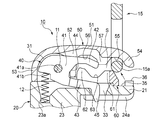
- the slide fastener slider 10 is a slider with an automatic stop function capable of attaching and detaching a handle to the body, and includes a body 20 as shown in FIGS. 1 and 2.
- Upper wing plate 21 and lower wing plate 22 that are spaced apart from each other in parallel, guide columns 23 that connect upper wing plate 21 and lower wing plate 22 at the front end, and left and right side edges of upper wing plate 21 And an upper flange 24a projecting downward along the left and right side edges of the lower blade 22 and a lower flange 24b projecting upward.
- left and right shoulders 25 separated by the guide pillars 23 are formed at the front of the body 20, and a rear opening 26 is formed at the rear of the body 20.
- a substantially Y-shaped element guide path 27 that connects the left and right shoulder openings 25 and the rear opening 26 is formed between the upper wing board 21 and the lower wing board 22.
- a passage through which the illustrated fastener element row is inserted is formed.
- the slide fastener slider 10 includes a lock member 40 that is supported by a column portion 31 erected on the front end portion of the upper surface of the upper blade 21 so as to be able to swing up and down, and the column portion 31 and the lock member 40 are moved upward.
- the cover member 50 covering from the top, the pillar portion 31, the lock member 40, and the pin 11 that is the rotation center of the lock member 40, and between the rear end portion of the cover member 50 and the upper blade plate 21.
- an opening / closing member 60 that opens and closes a gap S (hereinafter referred to as “insertion gap S”) through which the shaft portion 15a of the handle 15 is inserted.
- the column part 31 has left and right wall parts 31a and 31b spaced apart from each other so that the lock member 40 can be fitted therein.
- the pin 11 is inserted into the left and right wall parts 31a and 31b.
- the holes 31c are formed along the width direction.
- the lock member 40 has a base part 41 having a pin insertion hole 41 a through which the pin 11 is inserted, and extends rearward from the base part 41, and is arranged facing the vertical direction.
- the cover member 50 includes a top plate 51 that is curved upward and convex, a pair of left and right side plates 52 that extend downward from both side edges of the top plate 51, and a front end of the top plate 51. And a rear plate 54 extending downward from the rear end portion of the top plate 51.
- a retracting portion 55 is formed in a concave shape facing the body 20 on the lower end surface of the rear portion of the pair of left and right side plates 52.
- a handle housing portion 56 is formed in a concave shape facing the body 20 downward.
- a projecting piece 57 extending downward is formed between the retracting portion 55 and the handle accommodating portion 56.
- the lock member 40 is inserted between the left and right wall portions 31a and 31b of the column portion 31, and the pin 11 is inserted into the pin insertion hole 41a of the lock member 40 and the pin insertion holes 31c of the left and right wall portions 31a and 31b. As a result, it is pivotally supported with respect to the body 20 so as to be swingable up and down.
- the pin 11 is inserted into a through hole 52 a formed in the pair of left and right side plates 52 of the cover member 50, and the cover member 50 is fixed to the column portion 31 via the pin 11.
- the lock member 40 is urged by the first coil spring 12 built in the slider 10 so that the claw portion 45 of the lock member 40 enters the element guide path 27.
- the first coil spring 12 is contracted between a spring receiving surface 41b formed on the lower surface of the base 41 of the lock member 40 and a spring holding hole 23a formed on the guide post 23,
- the lock member 40 is swung with the pin 11 as a fulcrum when the spring receiving surface 41 b receives the urging force of the first coil spring 12 so that the claw portion 45 protrudes from the claw hole 33 to the element guide path 27.
- the spring receiving surface 41 b is formed in a surface that is recessed in a step shape above the lock member 40 at the front and lower portion of the pin insertion hole 41 a of the base 41 of the lock member 40.
- the spring holding hole 23 a extends along the vertical direction of the slider 10 and has a bottom surface on which the first coil spring 12 is placed.
- the opening / closing member 60 is formed in a substantially U shape in plan view so as not to come into contact with the lock member 40 when attached to the body 20.
- the first closing part 61 is formed in a substantially trapezoidal shape when viewed from the side
- the second closing part 62 is formed at the front end of the opening / closing member 60 and is substantially trapezoidal when viewed from the side
- the first closing part 61 and the second closing part are formed in a concave valley portion 63 formed between the portion 62.
- the opening / closing member 60 is provided to be slidable in the front-rear direction with respect to the body 20.
- the second coil spring 13 is contracted between the front end portion of the opening / closing member 60 and the spring holding groove 35 a formed in the guide groove 35, and the opening / closing member 60 is connected to the second coil spring 13. Is always urged toward the rear opening 26 side.
- a pair of left and right members that stop the opening / closing member 60 at a gap closing position that closes the insertion gap S and prevent the opening / closing member 60 from being removed from the guide groove 35.
- a stopper 36 is formed.
- the opening / closing member 60 is slid to a gap opening position that opens the insertion gap S, and the shaft portion 15a of the handle 15 is inserted into the insertion gap S, whereby the shaft portion 15a is inserted into the operating recess 44 of the lock member 40. Be contained.
- the second closing portion 62 of the opening / closing member 60 has a front surface 65, an upper surface 66, and a rear surface 67, and the upper surface 66 and the rear surface 67 are planar slopes extending forward. Is formed.
- the upper surface 66 is a surface that is inclined upward at an angle ⁇ 1 of 15 degrees to 30 degrees with respect to the lower surface of the opening / closing member 60 (the upper surface of the upper blade 21). Further, the inclination angle ⁇ 1 of the upper surface 66 is set smaller than the inclination angle ⁇ 2 of the rear surface 67.
- the rear surface 67 is a surface that is inclined upward with respect to the lower surface of the opening / closing member 60 at an angle ⁇ 2 of 45 to 60 degrees.
- the front surface 65 is formed on a flat slope extending forward and downward, and is a surface inclined downward at an angle ⁇ 3 of 45 ° to 70 ° with respect to the lower surface of the opening / closing member 60.
- the intersection of the upper surface 66 and the front surface 65 is disposed above the intersection of the upper surface 66 and the rear surface 67.
- the projecting piece 57 of the cover member 50 is arranged to face the opening / closing member 60 in the vertical direction, and the lower end surface 57a of the projecting piece 57 is when the opening / closing member 60 is stopped at the gap closed position.
- the upper surface 66 of the second closing part 62 of the opening / closing member 60 faces.
- the lower end surface 57 a of the projecting piece 57 is formed on a surface parallel to the upper surface of the upper blade 21.
- the upper surface 66 of the second closing portion 62 is a surface that is inclined forward with respect to the upper surface of the upper wing plate 21. Therefore, the gap between the upper surface 66 of the second closing portion 62 and the lower end surface 57 a of the projecting piece 57 is gradually narrowed toward the front of the body 20.
- the shaft portion 15 a of the handle 15 is pushed forward into the insertion gap S from the rear to the front, so that the opening / closing member 60 slides forward, and the shaft 15 a of the handle 15 is moved to the cover member 50.
- the opening / closing member 60 slides backward, and the shaft portion 15 a of the handle 15 enters the valley portion 63 of the opening / closing member 60.
- the shaft portion 15 a of the pull handle 15 is pushed further forward in the insertion gap S, whereby the opening / closing member 60 slides forward, and the shaft portion 15 a of the pull handle 15 is pulled by the handle of the cover member 50.
- the lock member 40 is inserted into the housing portion 56 while being lifted upward (see FIG. 7), and as shown in FIG. 8, the opening / closing member 60 slides backward, and the shaft portion 15a of the handle 15 operates the lock member 40. It is inserted into the recess 44.
- the shaft portion 15 a of the handle 15 is pushed forward from the retracting portion 55 of the cover member 50, so that the shaft portion 15 a is The shaft portion 15 a is guided forward and upward by contacting the upper surface 66 and the rear surface 67 of the second closing portion 62 of the opening / closing member 60. As a result, the shaft portion 15 a of the handle 15 is easily inserted into the operating recess 44 of the lock member 40.
- the shaft portion 15a of the pull handle 15 it is conceivable to reduce the height of the second closing portion 62 of the opening and closing member 60.
- the shaft portion 15 a comes into contact with the front corner portion of the projecting piece 57 of the cover member 50, and bending stress is generated to lift the cover member 50 upward.
- the upper surface 66 is formed on the front rising slope and the height of the second closing portion 62 is sufficiently secured, so that even if the handle 15 is pulled backward, FIG. As shown, the shaft portion 15a comes into contact with the front surface of the protruding piece 57 of the cover member 50, and bending stress for lifting the cover member 50 hardly occurs.
- the slide fastener slider 10 of the present embodiment since the upper surface 66 of the second closing portion 62 is formed on a flat slope extending forwardly, when the handle 15 is inserted, When the shaft portion 15 a of the handle 15 is guided upward by the inclined upper surface 66, the shaft portion 15 a automatically lifts the upper piece portion 42 of the lock member 40, and moves between the upper surface 66 and the upper piece portion 42. As a result, an action of entering the bottom (back) portion of the operating recess 44 occurs. Thereby, it is possible to easily insert the shaft portion 15 a of the handle 15 into the operation recess 44 of the lock member 40.
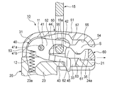
- the upper surface 66 of the second closing portion 162 of the opening / closing member 160 of the slide fastener slider 110 shown in FIGS. 11 and 12 is a flat slope extending forward. Is formed. Further, the front surface 65 and the rear surface 67 of the second closing portion 162 are the same as those in the first embodiment.
- the slide fastener slider 110 is a slider with an automatic stop function capable of attaching and detaching a handle to the body, and includes a body 120 as shown in FIGS. 11 and 12, and the body 120 is spaced apart in the vertical direction.
- the upper wing plate 121 and the lower wing plate 122 arranged in parallel, the guide pillar 123 connecting the upper wing plate 121 and the lower wing plate 122 at the front end, and the lower side along the left and right side edges of the upper wing plate 121.
- An upper flange 124a projecting toward the upper side, and a lower flange 124b projecting upward along the left and right side edges of the lower blade 122.
- left and right shoulders 125 separated by the guide pillar 123 are formed at the front of the body 120, and a rear opening 126 is formed at the rear of the body 120.
- a substantially Y-shaped element guide path 127 that communicates the left and right shoulder openings 125 and the rear opening 126 is formed between the upper wing plate 121 and the lower wing plate 122.
- a passage through which the pair of left and right fastener element rows shown in the figure is inserted is configured.
- the slide fastener slider 110 includes a lock member 140 that is supported by a column portion 131 erected on the front end portion of the upper surface of the upper wing plate 121 so as to be swingable up and down, and a front end portion of the upper surface of the upper wing plate 121.
- the cover member 150 that covers the column portion 131 and the lock member 140 from above, and a gap that is formed between the rear end portion of the cover member 150 and the upper blade 121 and through which the shaft portion 15a of the handle 15 is inserted.
- an opening / closing member 160 that opens and closes S (hereinafter referred to as “insertion gap S”).
- the column portion 131 includes left and right wall portions 131a and 131b spaced apart from each other so that the lock member 140 can be fitted therein, and a support convex portion 132 formed between the left and right wall portions 131a and 131b.
- the lock member 140 includes a base 141 supported by the column part 131 of the body 120, and an upper piece that extends from the base 141 toward the rear and is opposed to the vertical direction. Part 142 and lower piece part 143. Further, between the upper piece 142 and the lower piece 143, an operating recess 144 that opens toward the rear port 126 in the attached state and accommodates the shaft 15a of the pull handle 15 is formed. Further, a claw portion 145 that enters the element guide path 127 through a claw hole 133 formed in the upper blade 121 is formed at the tip of the lower piece portion 143 so as to face downward.
- a support concave portion 141 a that is swingably supported by the support convex portion 132 of the column portion 131 is formed on the lower surface of the base portion 141. Further, the claw hole 133 penetrates the element guide path 127 from the upper surface of the upper blade 121.
- the cover member 150 includes a top plate 151 that is curved upward, a pair of left and right side plates 152 that extend downward from both side edges of the top plate 151, and a front end of the top plate 151. And a rear plate 154 extending downward from the rear end portion of the top plate 51. Further, a retracting portion 155 is formed in a concave shape facing the body 120 on the lower end surface of the rear portion of the pair of left and right side plates 152. Further, on the lower end surface of the center portion of the pair of left and right side plates 152, a handle housing portion 156 is formed in a concave shape facing the body 120 downward. Further, a projecting piece 157 extending downward is formed between the retracting portion 155 and the handle accommodating portion 156.
- fitting pieces 158 that fit into fitting grooves 134 formed in the front end portion of the upper blade plate 121 are formed at the lower ends of the front end sides of the pair of left and right side plates 152, respectively. Then, by fitting the fitting piece 158 into the fitting groove 134 and caulking the pair of left and right side plates 152 to the recess 131c formed on the outer surface of the left and right wall portions 131a and 131b of the column portion 131, The front end portion of the cover member 150 is fixed to the front end portion of the upper blade 121 and is attached to the fuselage 120 in a cantilever manner along the front-rear direction.
- fitting grooves 134 are respectively formed on the left and right sides of the column part 131 and extend in the front-rear direction of the body 120.
- the fitting piece 158 protrudes laterally from the lower end of the pair of left and right side plates 152 of the cover member 150.
- a rectangular leaf spring 170 is provided between the lock member 140 and the cover member 150 to urge the claw portion 145 of the lock member 140 so as to enter the element guide path 127.
- Locking recesses 171 are formed on the front and rear ends of the leaf spring 170, respectively.
- the front and rear locking recesses 171 are formed on locking protrusions 151a formed on the front and rear of the top plate 151 of the cover member 150.
- the leaf springs 170 are mounted in the cover member 150 by locking them.
- the locking projection 151a is disposed inside the cover member 150 (in a space surrounded by the top plate 151, the pair of left and right side plates 152, the front plate 153, and the rear plate 154).
- the opening / closing member 160 is formed in a substantially U shape in plan view so as not to come into contact with the lock member 140 when attached to the body 120.
- the first closing portion 161 is formed in a substantially trapezoidal shape when viewed from the side
- the second closing portion 162 is formed at the front end portion of the opening and closing member 160 and is substantially trapezoidal when viewed from the side, and the first closing portion 161 and the second closing portion.
- a concave valley portion 163 formed between the first and second portions 162.
- guide portions 164 that are slidably fitted in guide grooves 135 formed along the front-rear direction on the upper surface of the rear portion of the upper blade 121 are formed at the lower ends of both side surfaces of the opening / closing member 160, respectively. Accordingly, the opening / closing member 160 is provided to be slidable in the front-rear direction with respect to the body 120.
- a coil spring 112 is contracted between the front end of the opening / closing member 160 and a spring holding groove 135 a formed in the guide groove 135, and the opening / closing member 160 is urged by the biasing force of the coil spring 112.
- the rear opening 126 is always urged.
- a pair of left and right members that stop the opening / closing member 160 at a gap closing position that closes the insertion gap S and prevent the opening / closing member 160 from being removed from the guide groove 135.
- a stopper 136 is formed. Then, the opening / closing member 160 is slid to a gap opening position that opens the insertion gap S, and the shaft portion 15a of the handle 15 is inserted into the insertion gap S, so that the shaft portion 15a is inserted into the operating recess 144 of the lock member 140. Be contained.
- the projecting piece 157 of the cover member 150 is arranged to face the opening / closing member 160 in the vertical direction, and the lower end surface 157a of the projecting piece 157 is when the opening / closing member 160 is stopped at the gap closed position. , Facing the upper surface 66 of the second closing part 162 of the opening and closing member 160. Further, the lower end surface 157 a of the projecting piece 157 is formed on a surface parallel to the upper surface of the upper blade 121.
- the upper surface 66 of the second closing portion 162 is a surface that is inclined forward with respect to the upper surface of the upper wing plate 121. Therefore, the gap between the upper surface 66 of the second closing portion 162 and the lower end surface 157 a of the projecting piece 157 gradually narrows toward the front of the body 120. About another structure and an effect, it is the same as that of the said 1st Embodiment.
Abstract
ロック部材の作動凹部に引手を挿入しやすくすることができるスライドファスナー用スライダーを提供する。 スライドファスナー用スライダー10は、胴体20と、胴体20の上面の前端部に立設される柱部31に揺動可能に支持されるロック部材40と、柱部31及びロック部材40を上方から覆うカバー部材50と、カバー部材50の後端部と胴体20との間に形成され、引手15の軸部15aが挿通される間隙Sを開閉する開閉部材60と、を備え、開閉部材60は、開閉部材60の後端部に形成され、側面視略台形状の第1閉鎖部61と、開閉部材60の前端部に形成され、側面視略台形状の第2閉鎖部62と、を有し、第2閉鎖部62の上面66が前上りに延びる平面状の斜面に形成される。
Description
本発明は、スライドファスナー用スライダーに関し、より詳細には、引手を胴体に着脱可能なスライドファスナー用スライダーに関する。
従来のスライドファスナー用スライダーとしては、胴体と、胴体の上面に立設される柱部に支持されるロック部材と、柱部及びロック部材を上方から覆うカバー部材と、柱部、ロック部材、及びカバー部材を貫通し、ロック部材の回転中心となるピンと、カバー部材の端部と胴体との間に形成され、引手が挿通される間隙を開閉する開閉部材と、を備えるものが知られている(例えば、特許文献1参照)。
しかしながら、上記特許文献1に記載のスライドファスナー用スライダーでは、開閉部材の第2閉塞部の上面が胴体の上翼板と略平行に形成されているため、ロック部材の作動凹部に引手を挿入し難くなる場合があった。
本発明は、前述した事情に鑑みてなされたものであり、その目的は、ロック部材の作動凹部に引手を挿入しやすくすることができるスライドファスナー用スライダーを提供することにある。
本発明の上記目的は、下記の構成により達成される。
(1)胴体と、胴体の上面の前端部に立設される柱部に揺動可能に支持されるロック部材と、柱部及びロック部材を上方から覆うカバー部材と、カバー部材の後端部と胴体との間に形成され、引手の軸部が挿通される間隙を開閉する開閉部材と、を備え、開閉部材が胴体に対して前後方向に摺動可能に設けられるスライドファスナー用スライダーであって、開閉部材は、開閉部材の後端部に形成され、側面視略台形状の第1閉鎖部と、開閉部材の前端部に形成され、側面視略台形状の第2閉鎖部と、を有し、第2閉鎖部の上面が前上りに延びる平面状の斜面に形成されることを特徴とするスライドファスナー用スライダー。
(2)第2閉鎖部は、上面、前面、及び後面を有し、後面が前上りに延びる平面状の斜面に形成され、上面の傾斜角度が、後面の傾斜角度よりも小さいことを特徴とする(1)に記載のスライドファスナー用スライダー。
(3)カバー部材は、天板と、天板の両側縁から下方に延びる左右一対の側面板と、天板の前端部から下方に延びる前面板と、天板の後端部から下方に延びる後面板と、を有し、左右一対の側面板は、その下端面において、下向きに凹状に形成される退避部及び引手収容部と、退避部と引手収容部との間に形成され、下方に延びる突片と、を有し、第2閉鎖部の上面は、突片の下端面と対向して配置され、上面と突片の下端面との間の隙間が、胴体の前方に向けて漸次狭まることを特徴とする(1)又は(2)に記載のスライドファスナー用スライダー。
本発明のスライドファスナー用スライダーによれば、開閉部材の第2閉鎖部の上面が前上りに延びる平面状の斜面に形成されるため、引手の軸部が作動凹部の底(奥)部分に入り込もうとする作用が生じて、ロック部材の作動凹部に引手の軸部を挿入しやすくすることができる。
以下、本発明に係るスライドファスナー用スライダーの各実施形態について、図面に基づいて詳細に説明する。なお、以後の説明において、上側とは図2の紙面に対して上側、下側とは図2の紙面に対して下側、前側とは図2の紙面に対して左側、後側とは図2の紙面に対して右側、右側とは図2の紙面に対して奥側、左側とは図2の紙面に対して手前側とする。また、スライダーの左右方向は幅方向ともいう。
(第1実施形態)
まず、図1~図9を参照して、本発明に係るスライドファスナー用スライダーの第1実施形態について説明する。
まず、図1~図9を参照して、本発明に係るスライドファスナー用スライダーの第1実施形態について説明する。
本実施形態のスライドファスナー用スライダー10は、引手を胴体に着脱可能な自動停止機能付きスライダーであって、図1及び図2に示すように、胴体20を備えており、この胴体20は、上下方向に離間して並行に配置される上翼板21及び下翼板22と、上翼板21及び下翼板22を前端部において連結する案内柱23と、上翼板21の左右両側縁に沿って下方に向けて突設される上側フランジ24aと、下翼板22の左右両側縁に沿って上方に向けて突設される下側フランジ24bと、を備える。これにより、胴体20の前部には案内柱23により分離された左右の肩口25が形成され、胴体20の後部には後口26が形成される。そして、上翼板21と下翼板22との間には、左右の肩口25と後口26とを連通する略Y字状のエレメント案内路27が形成され、このエレメント案内路27は、不図示のファスナーエレメント列を挿通させる通路を構成する。
また、スライドファスナー用スライダー10は、上翼板21の上面の前端部に立設される柱部31に上下に揺動可能に支持されるロック部材40と、柱部31及びロック部材40を上方から覆うカバー部材50と、柱部31、ロック部材40、及びカバー部材50を貫通し、ロック部材40の回転中心となるピン11と、カバー部材50の後端部と上翼板21との間に形成され、引手15の軸部15aが挿通される間隙S(以下、「挿通間隙S」と称する)を開閉する開閉部材60と、を備える。
柱部31は、ロック部材40が嵌め込み可能な間隔をあけて離間した左右の壁部31a,31bを有しており、この左右の壁部31a,31bには、ピン11が挿通されるピン挿通穴31cが幅方向に沿ってそれぞれ形成されている。
ロック部材40は、図1及び図2に示すように、ピン11が挿通されるピン挿通穴41aを有する基部41と、基部41から後方に向けてそれぞれ延び、上下方向に対向して配置される上片部42及び下片部43と、を有する。また、上片部42と下片部43との間には、取付状態において、後口26側に向かって開口し、引手15の軸部15aを収容する作動凹部44が形成されている。また、下片部43の先端部には、上翼板21に形成される爪穴33を介してエレメント案内路27に入り込む爪部45が下方に向けて形成されている。また、爪穴33は、上翼板21の上面からエレメント案内路27に貫通している。
カバー部材50は、図1及び図2に示すように、上向きに凸状に湾曲した天板51と、天板51の両側縁から下方に延びる左右一対の側面板52と、天板51の前端部から下方に延びる前面板53と、天板51の後端部から下方に延びる後面板54と、を有する。また、左右一対の側面板52の後部の下端面には、退避部55が胴体20に対向して下向きに凹状に形成されている。また、左右一対の側面板52の中央部の下端面には、引手収容部56が胴体20に対向して下向きに凹状に形成されている。また、退避部55と引手収容部56との間には、下方に延びる突片57が形成されている。
そして、ロック部材40は、柱部31の左右の壁部31a,31b間に挿入され、ロック部材40のピン挿通穴41a及び左右の壁部31a,31bのピン挿通穴31cにピン11が挿通されることにより、胴体20に対して上下に揺動可能に軸支される。また、ピン11は、カバー部材50の左右一対の側面板52に形成される貫通穴52aに挿入されており、カバー部材50は、ピン11を介して柱部31に対して固定される。
また、図2に示すように、ロック部材40は、スライダー10に内蔵された第1コイルばね12により、ロック部材40の爪部45がエレメント案内路27に入り込むように付勢されている。具体的には、ロック部材40の基部41の下面に形成されるばね受け面41bと案内柱23に形成されるばね保持孔23aとの間に、第1コイルばね12が縮設されており、ロック部材40は、この第1コイルばね12の付勢力をばね受け面41bが受けることによりピン11を支点にして揺動し、爪部45が爪穴33からエレメント案内路27に突出するように常時付勢されている。なお、ばね受け面41bは、ロック部材40の基部41のピン挿通穴41aの前方且つ下方部分において、ロック部材40の上方へ段差状に窪んだ面に形成される。また、ばね保持孔23aは、スライダー10の上下方向に沿って延びており、第1コイルばね12を載せるための底面を有する。
開閉部材60は、図1及び図2に示すように、胴体20に取り付けられた状態においてロック部材40と接触しないように、平面視略U字状に形成されており、開閉部材60の後端部に形成され、側面視略台形状の第1閉鎖部61と、開閉部材60の前端部に形成され、側面視略台形状の第2閉鎖部62と、第1閉鎖部61と第2閉鎖部62との間に形成される凹状の谷部63と、を有する。
また、開閉部材60の両側面の下端部には、上翼板21の後部上面に前後方向に沿って形成されるガイド溝35にスライド可能に嵌合するガイド部64がそれぞれ形成されている。これにより、開閉部材60は、胴体20に対して前後方向に摺動可能に設けられる。また、開閉部材60の前端部とガイド溝35内に形成されるばね保持溝35aとの間には、第2コイルばね13が縮設されており、開閉部材60は、この第2コイルばね13の付勢力により、後口26側に常時付勢されている。
また、上翼板21の上面の後端部には、開閉部材60を挿通間隙Sを閉鎖する間隙閉鎖位置にて停止すると共に、開閉部材60のガイド溝35からの離脱を阻止する左右一対のストッパ36が形成される。そして、開閉部材60を挿通間隙Sを開放する間隙開放位置へとスライドさせ、引手15の軸部15aを挿通間隙Sに挿通させることにより、軸部15aは、ロック部材40の作動凹部44内に収容される。
そして、図3に示すように、開閉部材60の第2閉鎖部62は、前面65、上面66、及び後面67を有し、その上面66及び後面67は、前上りに延びる平面状の斜面に形成されている。また、上面66は、開閉部材60の下面(上翼板21の上面)に対して15度~30度の角度θ1で上り傾斜する面である。さらに、上面66の傾斜角度θ1は、後面67の傾斜角度θ2よりも小さく設定されている。
また、後面67は、開閉部材60の下面に対して45度~60度の角度θ2で上り傾斜する面である。また、前面65は、前下りで延びる平面状の斜面に形成され、開閉部材60の下面に対して45度~70度の角度θ3で下り傾斜する面である。また、上面66と前面65の交点は、上面66と後面67の交点よりも上方に配置されている。
また、カバー部材50の突片57は、開閉部材60と上下方向に対向して配置されており、その突片57の下端面57aは、開閉部材60が隙閉鎖位置にて停止している時、開閉部材60の第2閉鎖部62の上面66と対面する。また、突片57の下端面57aは、上翼板21の上面と平行な面に形成される。そして、突片57の下端面57aが上翼板21の上面と平行な面であるのに、第2閉鎖部62の上面66が上翼板21の上面に対して前上りに傾斜する面であるので、第2閉鎖部62の上面66と突片57の下端面57aとの間の隙間が、胴体20の前方に向けて漸次狭まるようになっている。
次に、図4~図8を参照して、スライドファスナー用スライダー10に引手15を取り付ける手順を説明する。
まず、図4に示すように、引手15の軸部15aを挿通間隙S内に後方から前方に押し込むことにより、開閉部材60が前方にスライドして、引手15の軸部15aがカバー部材50の退避部55内に入り込むと共に、図5に示すように、開閉部材60が後方にスライドして、引手15の軸部15aが開閉部材60の谷部63に入り込む。
次いで、図6に示すように、引手15の軸部15aを挿通間隙S内において更に前方に押し込むことにより、開閉部材60が前方にスライドして、引手15の軸部15aがカバー部材50の引手収容部56内にロック部材40を上方に持ち上げながら入り込む(図7参照)と共に、図8に示すように、開閉部材60が後方にスライドして、引手15の軸部15aがロック部材40の作動凹部44に挿入される。
このように構成されたスライドファスナー用スライダー10では、図6及び図7に示すように、引手15の軸部15aがカバー部材50の退避部55内から前方に押し込まれることにより、軸部15aが開閉部材60の第2閉鎖部62の上面66及び後面67に接触して、軸部15aが前方且つ上方に案内される。これにより、引手15の軸部15aがロック部材40の作動凹部44に容易に挿入される。
ここで、引手15の軸部15aを挿入しやすくするために、開閉部材60の第2閉鎖部62の高さを低くすることも考えられるが、この場合、引手15が後方に引っ張られると、図10に示すように、軸部15aがカバー部材50の突片57の前方角部に接触して、カバー部材50を上方に持ち上げようとする曲げ応力が発生してしまう。しかし、本実施形態では、上面66を前上りの斜面に形成して、第2閉鎖部62の高さを十分に確保しているので、引手15が後方に引っ張られたとしても、図9に示すように、軸部15aがカバー部材50の突片57の前面に接触して、カバー部材50を持ち上げようとする曲げ応力はほぼ発生しない。
以上説明したように、本実施形態のスライドファスナー用スライダー10によれば、第2閉鎖部62の上面66が前上りに延びる平面状の斜面に形成されるため、引手15を挿入する際に、引手15の軸部15aが斜面状の上面66により上方に案内されると、軸部15aが、ロック部材40の上片部42を自動的に持ち上げ、上面66と上片部42との間を通って、作動凹部44の底(奥)部分に入り込もうとする作用が生じる。これにより、ロック部材40の作動凹部44に引手15の軸部15aを挿入しやすくすることができる。
(第2実施形態)
次に、図11及び図12を参照して、本発明に係るスライドファスナー用スライダーの第2実施形態について説明する。なお、上記第1実施形態と同一又は同等部分については、図面に同一符号を付してその説明を省略或いは簡略化する。
次に、図11及び図12を参照して、本発明に係るスライドファスナー用スライダーの第2実施形態について説明する。なお、上記第1実施形態と同一又は同等部分については、図面に同一符号を付してその説明を省略或いは簡略化する。
本実施形態では、上記第1実施形態と同様に、図11及び図12に示すスライドファスナー用スライダー110の開閉部材160の第2閉鎖部162の上面66が、前上りに延びる平面状の斜面に形成されている。また、第2閉鎖部162の前面65及び後面67も上記第1実施形態と同様である。
スライドファスナー用スライダー110は、引手を胴体に着脱可能な自動停止機能付きスライダーであって、図11及び図12に示すように、胴体120を備えており、この胴体120は、上下方向に離間して並行に配置される上翼板121及び下翼板122と、上翼板121及び下翼板122を前端部において連結する案内柱123と、上翼板121の左右両側縁に沿って下方に向けて突設される上側フランジ124aと、下翼板122の左右両側縁に沿って上方に向けて突設される下側フランジ124bと、を備える。これにより、胴体120の前部には案内柱123により分離された左右の肩口125が形成され、胴体120の後部には後口126が形成される。そして、上翼板121と下翼板122との間には、左右の肩口125と後口126とを連通する略Y字状のエレメント案内路127が形成され、このエレメント案内路127は、不図示の左右一対のファスナーエレメント列を挿通させる通路を構成する。
また、スライドファスナー用スライダー110は、上翼板121の上面の前端部に立設される柱部131に上下に揺動可能に支持されるロック部材140と、上翼板121の上面の前端部に取り付けられ、柱部131及びロック部材140を上方から覆うカバー部材150と、カバー部材150の後端部と上翼板121との間に形成され、引手15の軸部15aが挿通される間隙S(以下、「挿通間隙S」と称する)を開閉する開閉部材160と、を備える。
柱部131は、ロック部材140が嵌め込み可能な間隔をあけて離間した左右の壁部131a,131bと、左右の壁部131a,131b間に形成される支持凸部132と、を有する。
ロック部材140は、図11及び図12に示すように、胴体120の柱部131に支持される基部141と、基部141から後方に向けてそれぞれ延び、上下方向に対向して配置される上片部142及び下片部143と、を有する。また、上片部142と下片部143との間には、取付状態において、後口126側に向かって開口し、引手15の軸部15aを収容する作動凹部144が形成されている。また、下片部143の先端部には、上翼板121に形成される爪穴133を介してエレメント案内路127に入り込む爪部145が下方に向けて形成されている。また、基部141の下面には、柱部131の支持凸部132に揺動可能に支持される支持凹部141aが形成されている。また、爪穴133は、上翼板121の上面からエレメント案内路127に貫通している。
カバー部材150は、図11及び図12に示すように、上向きに凸状に湾曲した天板151と、天板151の両側縁から下方に延びる左右一対の側面板152と、天板151の前端部から下方に延びる前面板153と、天板51の後端部から下方に延びる後面板154と、を有する。また、左右一対の側面板152の後部の下端面には、退避部155が胴体120に対向して下向きに凹状に形成されている。また、左右一対の側面板152の中央部の下端面には、引手収容部156が胴体120に対向して下向きに凹状に形成されている。また、退避部155と引手収容部156との間には、下方に延びる突片157が形成されている。
また、左右一対の側面板152の前端側下端部には、上翼板121の前端部に形成される嵌合溝134に嵌合する嵌合片158がそれぞれ形成されている。そして、この嵌合片158を嵌合溝134に嵌合し、左右一対の側面板152を柱部131の左右の壁部131a,131bの外側面に形成される凹部131cにかしめることによって、カバー部材150は、その前端部が上翼板121の前端部に固定され、胴体120に対して前後方向に沿って片持状に取り付けられる。また、嵌合溝134は、柱部131の左右にそれぞれ形成され、胴体120の前後方向に延びている。また、嵌合片158は、カバー部材150の左右一対の側面板152の下端から側方へ突出している。
また、ロック部材140とカバー部材150との間には、ロック部材140の爪部145がエレメント案内路127に入り込むように付勢する長方形の板ばね170が設けられている。この板ばね170の前後端部には、係止凹部171がそれぞれ形成されており、この前後の係止凹部171を、カバー部材150の天板151の前後に形成される係止凸部151aにそれぞれ係止させることにより、カバー部材150内に板ばね170が装着される。また、係止凸部151aは、カバー部材150の内部(天板151、左右一対の側面板152、前面板153、及び後面板154により囲まれた空間内)に配置されている。
開閉部材160は、図11及び図12に示すように、胴体120に取り付けられた状態においてロック部材140と接触しないように、平面視略U字状に形成されており、開閉部材160の後端部に形成され、側面視略台形状の第1閉鎖部161と、開閉部材160の前端部に形成され、側面視略台形状の第2閉鎖部162と、第1閉鎖部161と第2閉鎖部162との間に形成される凹状の谷部163と、を有する。
また、開閉部材160の両側面の下端部には、上翼板121の後部上面に前後方向に沿って形成されるガイド溝135にスライド可能に嵌合するガイド部164がそれぞれ形成されている。これにより、開閉部材160は、胴体120に対して前後方向に摺動可能に設けられる。また、開閉部材160の前端部とガイド溝135内に形成されるばね保持溝135aとの間には、コイルばね112が縮設されており、開閉部材160は、このコイルばね112の付勢力により、後口126側に常時付勢されている。
また、上翼板121の上面の後端部には、開閉部材160を挿通間隙Sを閉鎖する間隙閉鎖位置にて停止すると共に、開閉部材160のガイド溝135からの離脱を阻止する左右一対のストッパ136が形成されている。そして、開閉部材160を挿通間隙Sを開放する間隙開放位置へとスライドさせ、引手15の軸部15aを挿通間隙Sに挿通させることにより、軸部15aは、ロック部材140の作動凹部144内に収容される。
また、カバー部材150の突片157は、開閉部材160と上下方向に対向して配置されており、その突片157の下端面157aは、開閉部材160が隙閉鎖位置にて停止している時、開閉部材160の第2閉鎖部162の上面66と対面する。また、突片157の下端面157aは、上翼板121の上面と平行な面に形成される。そして、突片157の下端面157aが上翼板121の上面と平行な面であるのに、第2閉鎖部162の上面66が上翼板121の上面に対して前上りに傾斜する面であるので、第2閉鎖部162の上面66と突片157の下端面157aとの間の隙間が、胴体120の前方に向けて漸次狭まるようになっている。
その他の構成及び作用効果については、上記第1実施形態と同様である。
その他の構成及び作用効果については、上記第1実施形態と同様である。
なお、本発明は上記実施形態に例示したものに限定されるものではなく、本発明の要旨を逸脱しない範囲において適宜変更可能である。
10,110 スライドファスナー用スライダー
20,120 胴体
31,131 柱部
40,140 ロック部材
50,150 カバー部材
51,151 天板
52,152 側面板
53,153 前面板
54,154 後面板
55,155 退避部
56,156 引手収容部
57,157 突片
57a,157a 下端面
60,160 開閉部材
61,161 第1閉鎖部
62,162 第2閉鎖部
65 前面
66 上面
67 後面
15 引手
15a 軸部
S 挿通間隙
θ1 上面の傾斜角度
θ2 後面の傾斜角度
θ3 前面の傾斜角度
20,120 胴体
31,131 柱部
40,140 ロック部材
50,150 カバー部材
51,151 天板
52,152 側面板
53,153 前面板
54,154 後面板
55,155 退避部
56,156 引手収容部
57,157 突片
57a,157a 下端面
60,160 開閉部材
61,161 第1閉鎖部
62,162 第2閉鎖部
65 前面
66 上面
67 後面
15 引手
15a 軸部
S 挿通間隙
θ1 上面の傾斜角度
θ2 後面の傾斜角度
θ3 前面の傾斜角度
Claims (3)
- 胴体(20,120)と、
前記胴体の上面の前端部に立設される柱部(31,131)に揺動可能に支持されるロック部材(40,140)と、
前記柱部及び前記ロック部材を上方から覆うカバー部材(50,150)と、
前記カバー部材の後端部と前記胴体との間に形成され、引手(15)の軸部(15a)が挿通される間隙(S)を開閉する開閉部材(60,160)と、を備え、
前記開閉部材が前記胴体に対して前後方向に摺動可能に設けられるスライドファスナー用スライダー(10,110)であって、
前記開閉部材は、前記開閉部材の後端部に形成され、側面視略台形状の第1閉鎖部(61,161)と、前記開閉部材の前端部に形成され、側面視略台形状の第2閉鎖部(62,162)と、を有し、
前記第2閉鎖部の上面(66)が前上りに延びる平面状の斜面に形成されることを特徴とするスライドファスナー用スライダー。 - 前記第2閉鎖部(62,162)は、前記上面(66)、前面(65)、及び後面(67)を有し、
前記後面が前上りに延びる平面状の斜面に形成され、
前記上面の傾斜角度(θ1)が、前記後面の傾斜角度(θ2)よりも小さいことを特徴とする請求項1に記載のスライドファスナー用スライダー。 - 前記カバー部材(50,150)は、天板(51,151)と、前記天板の両側縁から下方に延びる左右一対の側面板(52,152)と、前記天板の前端部から下方に延びる前面板(53,153)と、前記天板の後端部から下方に延びる後面板(54,154)と、を有し、
前記左右一対の側面板は、その下端面において、下向きに凹状に形成される退避部(55,155)及び引手収容部(56,156)と、前記退避部と前記引手収容部との間に形成され、下方に延びる突片(57,157)と、を有し、
前記第2閉鎖部(62,162)の前記上面(66)は、前記突片の下端面(57a,157a)と対向して配置され、前記上面と前記突片の前記下端面との間の隙間が、前記胴体(20,120)の前方に向けて漸次狭まることを特徴とする請求項1又は2に記載のスライドファスナー用スライダー。
Priority Applications (4)
| Application Number | Priority Date | Filing Date | Title |
|---|---|---|---|
| PCT/JP2011/060992 WO2012153426A1 (ja) | 2011-05-12 | 2011-05-12 | スライドファスナー用スライダー |
| JP2013513871A JP5592563B2 (ja) | 2011-05-12 | 2011-05-12 | スライドファスナー用スライダー |
| CN201180070797.7A CN103517651B (zh) | 2011-05-12 | 2011-05-12 | 拉链用拉头 |
| TW101116995A TWI465205B (zh) | 2011-05-12 | 2012-05-11 | Zipper with slider |
Applications Claiming Priority (1)
| Application Number | Priority Date | Filing Date | Title |
|---|---|---|---|
| PCT/JP2011/060992 WO2012153426A1 (ja) | 2011-05-12 | 2011-05-12 | スライドファスナー用スライダー |
Publications (1)
| Publication Number | Publication Date |
|---|---|
| WO2012153426A1 true WO2012153426A1 (ja) | 2012-11-15 |
Family
ID=47138924
Family Applications (1)
| Application Number | Title | Priority Date | Filing Date |
|---|---|---|---|
| PCT/JP2011/060992 WO2012153426A1 (ja) | 2011-05-12 | 2011-05-12 | スライドファスナー用スライダー |
Country Status (4)
| Country | Link |
|---|---|
| JP (1) | JP5592563B2 (ja) |
| CN (1) | CN103517651B (ja) |
| TW (1) | TWI465205B (ja) |
| WO (1) | WO2012153426A1 (ja) |
Cited By (1)
| Publication number | Priority date | Publication date | Assignee | Title |
|---|---|---|---|---|
| JP2017217342A (ja) * | 2016-06-10 | 2017-12-14 | Ykk株式会社 | 調整具 |
Citations (4)
| Publication number | Priority date | Publication date | Assignee | Title |
|---|---|---|---|---|
| JPS6399511U (ja) * | 1986-12-19 | 1988-06-28 | ||
| JPH0432974Y2 (ja) * | 1986-12-19 | 1992-08-07 | ||
| JPH10295415A (ja) * | 1997-05-02 | 1998-11-10 | Ykk Corp | スライドファスナー用スライダー |
| JP2009106611A (ja) * | 2007-10-31 | 2009-05-21 | Ykk Corp | 自動停止機構付スライドファスナー用スライダー |
Family Cites Families (1)
| Publication number | Priority date | Publication date | Assignee | Title |
|---|---|---|---|---|
| JP4799452B2 (ja) * | 2007-03-16 | 2011-10-26 | Ykk株式会社 | スライドファスナー用スライダー |
-
2011
- 2011-05-12 JP JP2013513871A patent/JP5592563B2/ja active Active
- 2011-05-12 WO PCT/JP2011/060992 patent/WO2012153426A1/ja active Application Filing
- 2011-05-12 CN CN201180070797.7A patent/CN103517651B/zh active Active
-
2012
- 2012-05-11 TW TW101116995A patent/TWI465205B/zh active
Patent Citations (4)
| Publication number | Priority date | Publication date | Assignee | Title |
|---|---|---|---|---|
| JPS6399511U (ja) * | 1986-12-19 | 1988-06-28 | ||
| JPH0432974Y2 (ja) * | 1986-12-19 | 1992-08-07 | ||
| JPH10295415A (ja) * | 1997-05-02 | 1998-11-10 | Ykk Corp | スライドファスナー用スライダー |
| JP2009106611A (ja) * | 2007-10-31 | 2009-05-21 | Ykk Corp | 自動停止機構付スライドファスナー用スライダー |
Cited By (1)
| Publication number | Priority date | Publication date | Assignee | Title |
|---|---|---|---|---|
| JP2017217342A (ja) * | 2016-06-10 | 2017-12-14 | Ykk株式会社 | 調整具 |
Also Published As
| Publication number | Publication date |
|---|---|
| JP5592563B2 (ja) | 2014-09-17 |
| CN103517651A (zh) | 2014-01-15 |
| TWI465205B (zh) | 2014-12-21 |
| CN103517651B (zh) | 2016-01-20 |
| TW201247125A (en) | 2012-12-01 |
| JPWO2012153426A1 (ja) | 2014-07-28 |
Similar Documents
| Publication | Publication Date | Title |
|---|---|---|
| TWI376211B (ja) | ||
| JP5647730B2 (ja) | スライドファスナー用スライダー | |
| JP5647728B2 (ja) | スライドファスナー用スライダー | |
| WO2010058465A1 (ja) | 引手着脱可能なスライドファスナー用スライダー | |
| WO2013011591A1 (ja) | スライドファスナー用スライダー | |
| JP5592563B2 (ja) | スライドファスナー用スライダー | |
| TWI459914B (zh) | Zipper with the slider | |
| TWI465204B (zh) | Zipper with the slider | |
| TWI465206B (zh) | Zipper with slider | |
| JP5462978B2 (ja) | スライドファスナー用スライダー | |
| TWI510201B (zh) | Zipper with slider | |
| TWI580373B (zh) | Slip and zipper | |
| TW201311173A (zh) | 拉鏈用滑件 | |
| WO2016139789A1 (ja) | スライドファスナーのスライダー | |
| JP3205204U (ja) | スライドファスナー用スライダー | |
| JP4658645B2 (ja) | カードアダプタ | |
| KR101060409B1 (ko) | 슬라이드 파스너용 자동 잠김 슬라이더 | |
| WO2013030962A1 (ja) | スライドファスナー用スライダー |
Legal Events
| Date | Code | Title | Description |
|---|---|---|---|
| 121 | Ep: the epo has been informed by wipo that ep was designated in this application |
Ref document number: 11865262 Country of ref document: EP Kind code of ref document: A1 |
|
| ENP | Entry into the national phase |
Ref document number: 2013513871 Country of ref document: JP Kind code of ref document: A |
|
| NENP | Non-entry into the national phase |
Ref country code: DE |
|
| 122 | Ep: pct application non-entry in european phase |
Ref document number: 11865262 Country of ref document: EP Kind code of ref document: A1 |