WO2012148164A1 - 좌우편차를 고려한 자기유도식 급전장치, 집전장치 및 전력전달장치 - Google Patents
좌우편차를 고려한 자기유도식 급전장치, 집전장치 및 전력전달장치 Download PDFInfo
- Publication number
- WO2012148164A1 WO2012148164A1 PCT/KR2012/003181 KR2012003181W WO2012148164A1 WO 2012148164 A1 WO2012148164 A1 WO 2012148164A1 KR 2012003181 W KR2012003181 W KR 2012003181W WO 2012148164 A1 WO2012148164 A1 WO 2012148164A1
- Authority
- WO
- WIPO (PCT)
- Prior art keywords
- feed
- current collector
- core
- width direction
- power feeding
- Prior art date
Links
Images


Classifications
-
- B—PERFORMING OPERATIONS; TRANSPORTING
- B60—VEHICLES IN GENERAL
- B60L—PROPULSION OF ELECTRICALLY-PROPELLED VEHICLES; SUPPLYING ELECTRIC POWER FOR AUXILIARY EQUIPMENT OF ELECTRICALLY-PROPELLED VEHICLES; ELECTRODYNAMIC BRAKE SYSTEMS FOR VEHICLES IN GENERAL; MAGNETIC SUSPENSION OR LEVITATION FOR VEHICLES; MONITORING OPERATING VARIABLES OF ELECTRICALLY-PROPELLED VEHICLES; ELECTRIC SAFETY DEVICES FOR ELECTRICALLY-PROPELLED VEHICLES
- B60L5/00—Current collectors for power supply lines of electrically-propelled vehicles
- B60L5/005—Current collectors for power supply lines of electrically-propelled vehicles without mechanical contact between the collector and the power supply line
-
- B—PERFORMING OPERATIONS; TRANSPORTING
- B60—VEHICLES IN GENERAL
- B60L—PROPULSION OF ELECTRICALLY-PROPELLED VEHICLES; SUPPLYING ELECTRIC POWER FOR AUXILIARY EQUIPMENT OF ELECTRICALLY-PROPELLED VEHICLES; ELECTRODYNAMIC BRAKE SYSTEMS FOR VEHICLES IN GENERAL; MAGNETIC SUSPENSION OR LEVITATION FOR VEHICLES; MONITORING OPERATING VARIABLES OF ELECTRICALLY-PROPELLED VEHICLES; ELECTRIC SAFETY DEVICES FOR ELECTRICALLY-PROPELLED VEHICLES
- B60L53/00—Methods of charging batteries, specially adapted for electric vehicles; Charging stations or on-board charging equipment therefor; Exchange of energy storage elements in electric vehicles
- B60L53/10—Methods of charging batteries, specially adapted for electric vehicles; Charging stations or on-board charging equipment therefor; Exchange of energy storage elements in electric vehicles characterised by the energy transfer between the charging station and the vehicle
- B60L53/12—Inductive energy transfer
- B60L53/126—Methods for pairing a vehicle and a charging station, e.g. establishing a one-to-one relation between a wireless power transmitter and a wireless power receiver
-
- B—PERFORMING OPERATIONS; TRANSPORTING
- B60—VEHICLES IN GENERAL
- B60L—PROPULSION OF ELECTRICALLY-PROPELLED VEHICLES; SUPPLYING ELECTRIC POWER FOR AUXILIARY EQUIPMENT OF ELECTRICALLY-PROPELLED VEHICLES; ELECTRODYNAMIC BRAKE SYSTEMS FOR VEHICLES IN GENERAL; MAGNETIC SUSPENSION OR LEVITATION FOR VEHICLES; MONITORING OPERATING VARIABLES OF ELECTRICALLY-PROPELLED VEHICLES; ELECTRIC SAFETY DEVICES FOR ELECTRICALLY-PROPELLED VEHICLES
- B60L53/00—Methods of charging batteries, specially adapted for electric vehicles; Charging stations or on-board charging equipment therefor; Exchange of energy storage elements in electric vehicles
- B60L53/30—Constructional details of charging stations
- B60L53/35—Means for automatic or assisted adjustment of the relative position of charging devices and vehicles
- B60L53/36—Means for automatic or assisted adjustment of the relative position of charging devices and vehicles by positioning the vehicle
-
- B—PERFORMING OPERATIONS; TRANSPORTING
- B60—VEHICLES IN GENERAL
- B60L—PROPULSION OF ELECTRICALLY-PROPELLED VEHICLES; SUPPLYING ELECTRIC POWER FOR AUXILIARY EQUIPMENT OF ELECTRICALLY-PROPELLED VEHICLES; ELECTRODYNAMIC BRAKE SYSTEMS FOR VEHICLES IN GENERAL; MAGNETIC SUSPENSION OR LEVITATION FOR VEHICLES; MONITORING OPERATING VARIABLES OF ELECTRICALLY-PROPELLED VEHICLES; ELECTRIC SAFETY DEVICES FOR ELECTRICALLY-PROPELLED VEHICLES
- B60L53/00—Methods of charging batteries, specially adapted for electric vehicles; Charging stations or on-board charging equipment therefor; Exchange of energy storage elements in electric vehicles
- B60L53/30—Constructional details of charging stations
- B60L53/35—Means for automatic or assisted adjustment of the relative position of charging devices and vehicles
- B60L53/38—Means for automatic or assisted adjustment of the relative position of charging devices and vehicles specially adapted for charging by inductive energy transfer
- B60L53/39—Means for automatic or assisted adjustment of the relative position of charging devices and vehicles specially adapted for charging by inductive energy transfer with position-responsive activation of primary coils
-
- B—PERFORMING OPERATIONS; TRANSPORTING
- B60—VEHICLES IN GENERAL
- B60M—POWER SUPPLY LINES, AND DEVICES ALONG RAILS, FOR ELECTRICALLY- PROPELLED VEHICLES
- B60M7/00—Power lines or rails specially adapted for electrically-propelled vehicles of special types, e.g. suspension tramway, ropeway, underground railway
- B60M7/003—Power lines or rails specially adapted for electrically-propelled vehicles of special types, e.g. suspension tramway, ropeway, underground railway for vehicles using stored power (e.g. charging stations)
-
- H—ELECTRICITY
- H01—ELECTRIC ELEMENTS
- H01F—MAGNETS; INDUCTANCES; TRANSFORMERS; SELECTION OF MATERIALS FOR THEIR MAGNETIC PROPERTIES
- H01F38/00—Adaptations of transformers or inductances for specific applications or functions
- H01F38/14—Inductive couplings
-
- H—ELECTRICITY
- H02—GENERATION; CONVERSION OR DISTRIBUTION OF ELECTRIC POWER
- H02J—CIRCUIT ARRANGEMENTS OR SYSTEMS FOR SUPPLYING OR DISTRIBUTING ELECTRIC POWER; SYSTEMS FOR STORING ELECTRIC ENERGY
- H02J50/00—Circuit arrangements or systems for wireless supply or distribution of electric power
- H02J50/10—Circuit arrangements or systems for wireless supply or distribution of electric power using inductive coupling
- H02J50/12—Circuit arrangements or systems for wireless supply or distribution of electric power using inductive coupling of the resonant type
-
- H—ELECTRICITY
- H02—GENERATION; CONVERSION OR DISTRIBUTION OF ELECTRIC POWER
- H02J—CIRCUIT ARRANGEMENTS OR SYSTEMS FOR SUPPLYING OR DISTRIBUTING ELECTRIC POWER; SYSTEMS FOR STORING ELECTRIC ENERGY
- H02J7/00—Circuit arrangements for charging or depolarising batteries or for supplying loads from batteries
- H02J7/0042—Circuit arrangements for charging or depolarising batteries or for supplying loads from batteries characterised by the mechanical construction
- H02J7/0045—Circuit arrangements for charging or depolarising batteries or for supplying loads from batteries characterised by the mechanical construction concerning the insertion or the connection of the batteries
-
- H—ELECTRICITY
- H02—GENERATION; CONVERSION OR DISTRIBUTION OF ELECTRIC POWER
- H02J—CIRCUIT ARRANGEMENTS OR SYSTEMS FOR SUPPLYING OR DISTRIBUTING ELECTRIC POWER; SYSTEMS FOR STORING ELECTRIC ENERGY
- H02J2310/00—The network for supplying or distributing electric power characterised by its spatial reach or by the load
- H02J2310/40—The network being an on-board power network, i.e. within a vehicle
- H02J2310/48—The network being an on-board power network, i.e. within a vehicle for electric vehicles [EV] or hybrid vehicles [HEV]
-
- Y—GENERAL TAGGING OF NEW TECHNOLOGICAL DEVELOPMENTS; GENERAL TAGGING OF CROSS-SECTIONAL TECHNOLOGIES SPANNING OVER SEVERAL SECTIONS OF THE IPC; TECHNICAL SUBJECTS COVERED BY FORMER USPC CROSS-REFERENCE ART COLLECTIONS [XRACs] AND DIGESTS
- Y02—TECHNOLOGIES OR APPLICATIONS FOR MITIGATION OR ADAPTATION AGAINST CLIMATE CHANGE
- Y02T—CLIMATE CHANGE MITIGATION TECHNOLOGIES RELATED TO TRANSPORTATION
- Y02T10/00—Road transport of goods or passengers
- Y02T10/60—Other road transportation technologies with climate change mitigation effect
- Y02T10/70—Energy storage systems for electromobility, e.g. batteries
-
- Y—GENERAL TAGGING OF NEW TECHNOLOGICAL DEVELOPMENTS; GENERAL TAGGING OF CROSS-SECTIONAL TECHNOLOGIES SPANNING OVER SEVERAL SECTIONS OF THE IPC; TECHNICAL SUBJECTS COVERED BY FORMER USPC CROSS-REFERENCE ART COLLECTIONS [XRACs] AND DIGESTS
- Y02—TECHNOLOGIES OR APPLICATIONS FOR MITIGATION OR ADAPTATION AGAINST CLIMATE CHANGE
- Y02T—CLIMATE CHANGE MITIGATION TECHNOLOGIES RELATED TO TRANSPORTATION
- Y02T10/00—Road transport of goods or passengers
- Y02T10/60—Other road transportation technologies with climate change mitigation effect
- Y02T10/7072—Electromobility specific charging systems or methods for batteries, ultracapacitors, supercapacitors or double-layer capacitors
-
- Y—GENERAL TAGGING OF NEW TECHNOLOGICAL DEVELOPMENTS; GENERAL TAGGING OF CROSS-SECTIONAL TECHNOLOGIES SPANNING OVER SEVERAL SECTIONS OF THE IPC; TECHNICAL SUBJECTS COVERED BY FORMER USPC CROSS-REFERENCE ART COLLECTIONS [XRACs] AND DIGESTS
- Y02—TECHNOLOGIES OR APPLICATIONS FOR MITIGATION OR ADAPTATION AGAINST CLIMATE CHANGE
- Y02T—CLIMATE CHANGE MITIGATION TECHNOLOGIES RELATED TO TRANSPORTATION
- Y02T90/00—Enabling technologies or technologies with a potential or indirect contribution to GHG emissions mitigation
- Y02T90/10—Technologies relating to charging of electric vehicles
- Y02T90/12—Electric charging stations
-
- Y—GENERAL TAGGING OF NEW TECHNOLOGICAL DEVELOPMENTS; GENERAL TAGGING OF CROSS-SECTIONAL TECHNOLOGIES SPANNING OVER SEVERAL SECTIONS OF THE IPC; TECHNICAL SUBJECTS COVERED BY FORMER USPC CROSS-REFERENCE ART COLLECTIONS [XRACs] AND DIGESTS
- Y02—TECHNOLOGIES OR APPLICATIONS FOR MITIGATION OR ADAPTATION AGAINST CLIMATE CHANGE
- Y02T—CLIMATE CHANGE MITIGATION TECHNOLOGIES RELATED TO TRANSPORTATION
- Y02T90/00—Enabling technologies or technologies with a potential or indirect contribution to GHG emissions mitigation
- Y02T90/10—Technologies relating to charging of electric vehicles
- Y02T90/14—Plug-in electric vehicles
Definitions
- Embodiment of the present invention relates to a self-induction power supply device, current collector and power transmission device in consideration of left and right deviation. More specifically, when a moving object such as an electric vehicle is charged while driving on a road and is supplied with electric power for driving, a left and right deviation for effectively supplying electric power for driving even if a certain distance is moved left or right from a feeder line embedded in the road
- the present invention relates to a magnetic induction feeding device, a current collector, and a power transmission device in consideration.
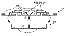
- FIG. 1A is a diagram illustrating a state in which an electric vehicle is driving on a road while receiving electric power supplied through a feed line embedded in a road
- FIG. 1B is a power supply core required for power transmission except for a car and a road in FIG. 1A.
- the feed line and the current collector are shown in simplified form.
- the electric vehicle 100 includes a feed core 112 and a feed line 114 when high frequency power is supplied to the feed line 114 positioned on the feed core 112 while driving on a road.
- a feed core 112 and a feed line 114 when high frequency power is supplied to the feed line 114 positioned on the feed core 112 while driving on a road.
- the principle of electromagnetic induction acting between the power supply device 110 and the current collector 130 is supplied with power necessary for driving.
- FIG. 1C is a view illustrating a cross section taken along line AA ′ in FIG. 1B as viewed in the X direction.
- FIG. 1C in order to mainly describe the state of the magnetic field, a detailed illustration of the reference number is omitted, and the reference number shown in the description of FIG. 1C refers to FIG. 1B.
- the magnetic flux generated by the feed line 114 generates magnetic flux in the direction of the arrow of the semicircle to generate induced electromotive force in the current collecting line 134.
- FIG. 2 is a diagram illustrating a magnetic field generated according to the positional relationship between the feed core 112, the feed line 114, and the current collector 130 in FIG. 1C.
- the current collector 130 is embedded in the road so that the current collector 130 of the electric vehicle 100 receives the maximum power Arrangement shapes of the power feeding core 112, the power feeding line 114, and the current collecting device 130 when the electric vehicle 100 travels on the road so that the electric vehicle 100 is located at a position (that is, when the current collecting device 130 is in the correct position).
- FIG. 2B illustrates a case in which the current collector 130 is located at a predetermined distance from the center of the feed core 112 and the feed line 114 to the left or the right (ie, The arrangement shape of the power feeding core 112, the power feeding line 114, and the current collecting device 130 of the current collector 130 when it is misaligned is illustrated and a magnetic field generated.
- the current collector line 134 wound around the current collector core 132 may be used.
- the output of the induced electromotive force can be generated to a normal magnitude.
- Arrows shown as semicircles in FIG. 2A conceptually show the direction of the magnetic field contributing to the induced electromotive force of the current collector 130.
- Figure 2 (B) is not only contributes to the induced electromotive force, but also contributes to the induced electromotive force when the electric vehicle 100 is driven so that the distance that the current collector 110 is misaligned occurs over a certain distance Since the amount of magnetic flux in the direction opposite to the direction is increased, there is a problem that power transfer from the power supply device 110 to the current collector 130 is not smoothly performed.
- one embodiment of the present invention when a moving object such as an electric vehicle is charged while driving on the road to receive the power required for driving the current collector mounted on the electric vehicle left or right from the feeder line embedded in the road As a result, even if a certain distance is to be able to effectively supply the power required for operation.
- the purpose of the present invention is to provide a cutout portion in the power feeding core to significantly reduce the amount of use of the core without significantly lowering the power transmission efficiency.
- the main feed portion having a predetermined width and length, and the shape of the cross section cut the feed main portion perpendicular to the longitudinal direction is the width direction
- the feed line may be wound adjacent to the feed protrusion.
- the feed line may be wound around the feed protrusion.
- the power feeding core may have a plurality of cutouts parallel to the width direction.
- the power feeding core may have a predetermined interval between the cutouts in the plurality of cutouts.
- a feed main portion having a predetermined width and length, and the shape of the cross section cut the feed main portion perpendicular to the longitudinal direction is the width direction E-shaped having the feed projections perpendicular to both the width direction and the longitudinal direction and protruding in the same direction at both left and right ends of the center projection in the same direction as the feed projections in the center portion of the width direction Feeding core; And a pair of feed lines wound around left and right ends of the feed main portion, respectively.
- the feed line may be wound adjacent to the feed protrusion or wound around the feed protrusion.
- the power feeding core may have a plurality of cutouts parallel to the width direction to divide the power feeding core into a plurality of core pieces.
- the feeding core may have a thickness greater than that of the core piece in the longitudinal direction.
- a feed main portion having a predetermined width and length, and the shape of the cross section cut the feed main portion perpendicular to the longitudinal direction is the width direction
- the power feeding core may have a plurality of cutouts parallel to the width direction to divide the power feeding core into a plurality of core pieces.
- the thickness of the cutout in the longitudinal direction may have a size substantially similar to the thickness of the core piece.
- the feeding core may have a constant distance between the cutouts in the plurality of cutouts.
- the shape of the current collector main portion having a predetermined width and length, and the shape of the cross section in which the current collector main portion is cut perpendicular to the longitudinal direction is the width direction
- the current collecting line may be wound around the current collecting protrusions protruding from the left end and the right end, respectively.
- the current collecting core may include an extension part extending in the width direction at each end of the current collecting protrusion protruding from the left end and the right end.
- the current collector may be mounted on a lower portion of the vehicle.
- a moving object such as an electric vehicle is charged while driving on a road and is supplied with power necessary for driving, it operates effectively even if a certain distance is deviated to the left or right from a feeder line embedded in the road. There is an effect of enabling to supply the power required for.
- the use amount of the core is greatly reduced without significantly lowering the power transmission efficiency.
- 1A is a diagram illustrating a state in which an electric vehicle is driving on a road while receiving electric power supplied through a feed line embedded in a road.
- FIG. 1B is a simplified diagram illustrating only a power supply core, a power supply line, and a current collector necessary for power transmission except for cars and roads in FIG. 1A.
- FIG. 1C is a view illustrating a cross section taken along line AA ′ in FIG. 1B as viewed in the X direction.
- FIG. 2 is a diagram illustrating a magnetic field generated according to the positional relationship between the feed core 112, the feed line 114, and the current collector 130 in FIG. 1C.
- 3A is a diagram illustrating a power transmission device according to a first embodiment of the present invention.
- 3B is a diagram illustrating a case in which the power feeding core is formed integrally in a U shape without a cutout and in a case where an E-shaped integral shape is formed without a cutout.
- FIG. 4 is a cross-sectional view taken along the line AA ′ of FIG. 3A and viewed in the X direction.
- FIG. 5 is a view illustrating a state of a magnetic field generated in the power transmission device of FIGS. 3A and 4.
- FIG. 6 is a diagram illustrating a power transmission device according to a second embodiment of the present invention.
- FIG. 7 is a cross-sectional view taken along the line AA ′ of FIG. 6 and viewed in the X direction.
- FIG. 8 is a diagram illustrating a magnetic field generated in the power transmission devices of FIGS. 6 and 7.
- FIG. 3A is a diagram illustrating a power transmission device according to a first embodiment of the present invention
- FIG. 4 is a cross-sectional view taken along the line AA ′ in the drawing of FIG. 3A and viewed in the X direction.
- Figure 3b is a diagram illustrating a case where the feed core is formed in a U-shaped integral body without a cutout and a case in which the feed core is formed in an E-shaped integrally without a cutout.
- the power transmission device includes a power feeding device 300 and a current collecting device 400.
- the power feeding device 300 may include a power feeding core 310, a power feeding line 320, and an input power source 330, and a current collecting device according to the first embodiment of the present invention.
- the 400 may include a current collecting core 410, a current collecting line 420, a current collecting circuit 430, and a battery 440.
- the feed core 310 has a feed main portion 312 having a predetermined width and length, and a cross-sectional shape obtained by cutting the feed main portion 312 perpendicular to the longitudinal direction of the feed core 310 has a width of the feed core 310.
- Feed projections 314 and 315 protruding at the left end and the right end in the direction.
- the feed protrusions 314 and 315 are perpendicular to both the width direction of the feed core 310 and the longitudinal direction of the feed core 310 so that the shape of the feed core 310 is U-shaped.
- the feed cores 314 and 315 are provided on the feed core 310 to facilitate the transfer of the magnetic field to the current collector 400.
- the power feeding core 310 further includes a center protrusion 316 protruding in the same direction as the power feeding protrusions 314 and 315 in the center of the width direction of the power feeding main portion 312. ) May have an E-shape to increase the total amount of the magnetic field transmitted to the current collector 400 compared to the U-shape.
- the pair of feed lines 320 is wound around the left end and the right end of the feed main portion 312, respectively.
- the left feed line 320a is wound around the left feed projection 314 in the longitudinal direction of the feed core 310 in the left end of the feed main portion 312, and the right feed line 320b is adjacent to the right feed projection 315.
- the longitudinal direction of the power feeding core 310 may be respectively wound on the right end of the power feeding main portion 312.
- the pair of feed lines 320a and 32b may be wound around the left and right feed protrusions 314 and 315, respectively.
- the power feeding core 310 may be integrally formed as shown in FIG. 3B, or may have a shape having a cutout 340 as shown in FIG. 3A.
- the feed core 310 has a plurality of cutouts 340 parallel to the width direction of the feed core 310 to divide the feed core 310 into a plurality of core pieces having an E-shape (or U-shape). It can also be shaped.
- the distance between the adjacent cutouts 340 may be configured to be constant, and the thickness of the cutouts 340 is greater than the thickness of the core piece having an E shape (or U shape), It may be similar or small.
- FIG. 3A By forming the cutout 340 in the power feeding core 310 as shown in FIG. 3A, when the power feeding core is formed with only half the capacity as compared to the capacity when the power feeding core is integrally formed as shown in FIG. 3B, FIG. 3A. In comparison with the case of the output induced in the current collector 400, a decrease of about 10% appears. However, since the capacity of the ferrite core used for the power feeding core 310 can be reduced to about half, the amount of reduction of the output induced in the current collector 400 is not large compared to saving the ferrite capacity.
- the current collector core 410, the current collector main portion 412 having a predetermined width and length, and the current collector protrusion 412 projecting the current collector main portion 412 in the same direction on the left and right ends in the width direction of the current collector core 410, respectively; 414 and 415, and the protruding directions of the current collector protrusions 414 and 415 are perpendicular to both the width direction of the current collector core 410 and the longitudinal direction of the current collector core 410 so that the current collector main part 412 is extended in the longitudinal direction.
- the shape of the cross section cut vertically should be shaped like a ⁇ . At this time, the current collector protrusions 414 and 415 protrude in a direction opposite to the feed protrusions 314 and 315.
- ends of the current collector protrusions 414 and 415 may include extension parts 416 and 417 extending in the width direction of the current collector core 410, respectively.
- the current collector protrusions 414 and 415 are provided with the extension portions 416 and 417 at the ends of the current collector protrusions 414 and 415 to increase the effective cross-sectional area on the magnetic path, thereby reducing the magnetoresistance.
- the shape of the extension may be a shape toward the outward from the current collector protrusions 414, 415 around the current collector main portion 412, as shown in reference numerals 416, 417, the current collector core 410 from the current collector protrusions (414, 415)
- the width direction of ()) may further include a portion protruding in the direction toward the center of the current collector main portion 412 (ie, opposite to the reference numerals 416, 417 relative to the current collector protrusions 414, 415).
- the current collector line 420 may be wound around the left current collector protrusion 414 and the right current collector protrusion 415 of the current collector core 410, and in some cases, may be wound around the current collector main part 412.
- the current collector circuit 430 may include a rectifier and a regulator.
- FIG. 5 is a view illustrating a state of a magnetic field generated in the power transmission device of FIGS. 3A and 4.
- reference numerals are omitted and reference numerals are used as reference numerals in FIG. 5.
- FIG. 5A illustrates a magnetic field generated when the current collector 400 is in a correct position so that the current collector 400 can receive the maximum power.
- FIG. 5B illustrates a current collector. The magnetic field generated when the device 400 is misaligned.
- the output of the induced electromotive force may be generated to the current collector line 420 wound around the current collector core 410 in a normal size.
- An arrow shown as a semicircle in FIG. 5A conceptually illustrates the direction of magnetic flux that contributes to the induced electromotive force of the current collector 400.
- the width of the power feeding core 110 is 72 cm
- the width of the current collecting device 130 is 110 cm
- the position of the current collecting device 130 as shown in FIG.
- the sum of the voltages generated at the current collector lines is 1651 V as a result of simulating the output current collected at the current collector line 134 under the condition that is the home position, the distance at which the current collector 130 is misaligned as shown in FIG. Is 30 cm
- the sum of the voltages generated in the current collector line 134 is 148 V, which can be seen that the generated voltage is greatly reduced.
- the voltage induced in the current collector 130 decreases, the induced current tends to decrease as well, so it can be seen that the output induced in the current collector 130 decreases rapidly.
- the width of the power feeding core 310 is 72 cm and the current collector 400 is 110 cm under the same conditions as in FIG. 2.
- the current collector 400 is the same as that of FIG. If the distance 400 is misaligned is 30 cm, the sum of the voltages generated at the current collector lines 420 is 1559 V, indicating that the amount of reduction in the generated voltages is not large, which is more effective than in the case of FIG. Can be.
- FIG. 6 is a view illustrating a power transmission device according to a second embodiment of the present invention
- Figure 7 is a view showing a cross-sectional view in the X direction by cutting along the line AA 'in FIG.
- the power transmission device includes a power feeding device 600 and a current collector 700.
- the feed line 620 is wound in the longitudinal direction of the feed core 610 at the center portion in the width direction of the feed main portion 612.
- FIG. 8 is a diagram illustrating a magnetic field generated in the power transmission devices of FIGS. 6 and 7.
- reference numerals are omitted and reference numerals are used as reference numerals in FIG. 8.
- FIG. 8A illustrates a case where the widthwise center portion of the current collector 700 is positioned above the widthwise center portion of the power feeding device 600 so that the current collector 700 can receive the maximum power (that is, FIG. 8B is a diagram illustrating a magnetic field generated when the current collector 700 is misaligned.
- the output of the induced electromotive force may be generated to the current collector line 720 wound around the current collector core 710 in a normal size.
- Arrows shown as semicircles in FIG. 8A conceptually show the direction of the magnetic field contributing to the induced electromotive force of the current collector 700.
- the amount of magnetic flux that does not contribute to the induced electromotive force increases as compared to the case where the current collector 700 is in the correct position. Since the amount of magnetic flux in a direction opposite to the direction contributing to is small, the voltage reduction width of the current collector 130 occurs less than when the current collector 130 is misaligned in a certain distance in FIG. 2.
- the width of the power feeding core 610 is 72 cm and the current collector 700 is 110 cm under the same condition as that of FIG. 5.
- the current collector 700 is misaligned as shown in FIG. 8B.
- the rate at which the generated voltage decreases is not large, which is more effective than in the case of FIG.
- the present invention when a moving object such as an electric vehicle is charged while driving on a road and receives power for driving, the present invention can effectively supply power for driving even if a certain distance is deviated to the left or right from a feeder line embedded in the road. It is a useful invention for generating an effect.
Abstract
Description
| 정위치에서의 출력전압 | 30 cm 미스얼라인먼트시의 출력전압 | 정위치 대비 미스얼라인먼트시의 출력전압 유지비율 | |
| 도 2 | 1651 V | 148 V | 9.0 % |
| 도 5 | 2063 V | 1559 V | 75.9 % |
| 도 8 | 2782 V | 1870 V | 67.2 % |
Claims (18)
- 급전장치에 있어서,소정의 폭과 길이를 갖는 급전주요부와, 상기 급전주요부를 상기 길이 방향에 수직하게 절단한 단면의 형상이 상기 폭 방향의 좌측 단부 및 우측 단부에 상기 폭 방향 및 상기 길이 방향 모두에 수직하고 서로 동일한 방향으로 돌출된 급전돌출부를 가져 U자 형상을 하는 급전코어; 및상기 급전주요부의 좌측 단부 및 우측 단부에 각각 권취된 한 쌍의 급전선을 포함하는 것을 특징으로 하는 급전장치.
- 제 1항에 있어서,상기 급전선은,상기 급전돌출부에 인접하여 권취되는 것을 특징으로 하는 급전장치.
- 제 1항에 있어서,상기 급전선은,상기 급전돌출부에 권취되는 것을 특징으로 하는 급전장치.
- 제 1항에 있어서,상기 급전코어는,상기 폭 방향과 평행한 복수개의 절개부를 갖는 것을 특징으로 하는 급전장치.
- 제 4항에 있어서,상기 급전코어는,상기 복수개의 절개부에서 각 절개부 사이는 일정한 간격을 갖는 것을 특징으로 하는 급전장치.
- 급전장치에 있어서,소정의 폭과 길이를 갖는 급전주요부와, 상기 급전주요부를 상기 길이 방향에 수직하게 절단한 단면의 형상이 상기 폭 방향의 좌측 단부 및 우측 단부에 상기 폭 방향 및 상기 길이 방향 모두에 수직하고 서로 동일한 방향으로 돌출된 급전돌출부를 가지고 상기 폭 방향의 중앙부에 상기 급전돌출부와 동일한 방향의 중앙돌출부를 가져 E자 형상을 하는 급전코어; 및상기 급전주요부의 좌측 단부 및 우측 단부에 각각 권취된 한 쌍의 급전선을 포함하는 것을 특징으로 하는 급전장치.
- 제 6항에 있어서,상기 급전선은,상기 급전돌출부에 인접하여 권취되거나 또는 상기 급전돌출부에 권취되는 것을 특징으로 하는 급전장치.
- 제 6항에 있어서,상기 급전코어는,상기 폭 방향과 평행한 복수개의 절개부를 가져 상기 급전코어를 복수개의 코어조각으로 나누는 것을 특징으로 하는 급전장치.
- 제 8항에 있어서,상기 급전코어는,상기 길이 방향에서 상기 절개부의 두께는 상기 코어조각의 두께보다 큰 것을 특징으로 하는 급전장치.
- 급전장치에 있어서,소정의 폭과 길이를 갖는 급전주요부와, 상기 급전주요부를 상기 길이 방향에 수직하게 절단한 단면의 형상이 상기 폭 방향의 좌측 단부 및 우측 단부에 상기 폭 방향 및 상기 길이 방향 모두에 수직하고 서로 동일한 방향으로 돌출된 급전돌출부를 가져 U자 형상을 하는 급전코어; 및상기 급전주요부의 폭 방향의 중앙부에 상기 급전코어의 길이 방향으로 권취된 급전선을 포함하는 것을 특징으로 하는 급전장치.
- 제 10항에 있어서,상기 급전코어는,상기 폭 방향과 평행한 복수개의 절개부를 가져 상기 급전코어를 복수개의 코어조각으로 나누는 것을 특징으로 하는 급전장치.
- 제 11항에 있어서,상기 급전코어에서,상기 길이 방향에서 상기 절개부의 두께는 상기 코어조각의 두께와 대략 비슷한 크기를 갖는 것을 특징으로 하는 급전장치.
- 제 12항에 있어서,상기 급전코어는,상기 복수개의 절개부에서 절개부 사이의 거리는 일정한 것을 특징으로 하는 급전장치.
- 집전장치에 있어서,소정의 폭과 길이를 갖는 집전주요부와, 상기 집전주요부를 상기 길이 방향에 수직하게 절단한 단면의 형상이 상기 폭 방향 및 상기 길이 방향 모두에 수직하고 서로 동일한 방향으로 상기 폭 방향의 좌측 단부 및 우측 단부에 돌출된 집전돌출부를 가져 ∩ 형상을 하는 집전코어; 및상기 집전코어에 권취되는 집전선을 포함하는 것을 특징으로 하는 집전장치.
- 제 14항에 있어서,상기 집전선은,상기 좌측 단부 및 상기 우측 단부에 돌출된 집전돌출부에 각각 권취되는 것을 특징으로 하는 집전장치.
- 제 14항에 있어서,상기 집전코어는,상기 좌측 단부 및 상기 우측 단부에 돌출된 집전돌출부의 끝에 각각 상기 폭 방향으로 연장된 연장부를 구비하는 것을 특징으로 하는 집전장치.
- 제 14항에 있어서,상기 집전장치는, 차량의 하부에 장착되는 것을 특징으로 하는 집전장치.
- 전력전달장치에 있어서,제 1항 내지 제 13항 중에서 어느 한 항의 급전장치; 및제 14 내지 제 17항 중에서 어느 한 항의 집전장치를 포함하되,상기 급전돌출부와 상기 집전돌출부는 서로 대향된 방향으로 돌출된 것을 특징으로 하는 전력전달장치.
Priority Applications (5)
| Application Number | Priority Date | Filing Date | Title |
|---|---|---|---|
| AU2012248971A AU2012248971B2 (en) | 2011-04-26 | 2012-04-25 | Feed apparatus, current collector, and power transfer apparatus of the magnetic induction type, considering lateral deviation |
| EP12777602.9A EP2704292B1 (en) | 2011-04-26 | 2012-04-25 | Feed apparatus, current collector, and power transfer apparatus of the magnetic induction type, considering lateral deviation |
| CN201280013289.XA CN103548236B (zh) | 2011-04-26 | 2012-04-25 | 考虑到横向偏差的磁感应式供电装置、集电装置及电力输送装置 |
| US14/113,724 US9656562B2 (en) | 2011-04-26 | 2012-04-25 | Feed apparatus, current collector, and power transfer apparatus of the magnetic induction type, considering lateral deviation |
| JP2014501020A JP2014515247A (ja) | 2011-04-26 | 2012-04-25 | 左右偏差を考慮した磁気誘導式給電装置、集電装置、及び電力伝達装置 |
Applications Claiming Priority (2)
| Application Number | Priority Date | Filing Date | Title |
|---|---|---|---|
| KR10-2011-0039206 | 2011-04-26 | ||
| KR1020110039206A KR101182376B1 (ko) | 2011-04-26 | 2011-04-26 | 좌우편차를 고려한 자기유도식 급전장치, 집전장치 및 전력전달장치 |
Publications (1)
| Publication Number | Publication Date |
|---|---|
| WO2012148164A1 true WO2012148164A1 (ko) | 2012-11-01 |
Family
ID=47072566
Family Applications (1)
| Application Number | Title | Priority Date | Filing Date |
|---|---|---|---|
| PCT/KR2012/003181 WO2012148164A1 (ko) | 2011-04-26 | 2012-04-25 | 좌우편차를 고려한 자기유도식 급전장치, 집전장치 및 전력전달장치 |
Country Status (7)
| Country | Link |
|---|---|
| US (1) | US9656562B2 (ko) |
| EP (1) | EP2704292B1 (ko) |
| JP (1) | JP2014515247A (ko) |
| KR (1) | KR101182376B1 (ko) |
| CN (1) | CN103548236B (ko) |
| AU (1) | AU2012248971B2 (ko) |
| WO (1) | WO2012148164A1 (ko) |
Families Citing this family (11)
| Publication number | Priority date | Publication date | Assignee | Title |
|---|---|---|---|---|
| KR101438394B1 (ko) * | 2012-11-19 | 2014-09-17 | 한국과학기술원 | 차량 방향에 강인한 급전선로 및 집전장치 |
| KR101384691B1 (ko) * | 2012-11-23 | 2014-04-21 | 한국과학기술원 | 전기차량용 슬림 픽업 |
| KR102238917B1 (ko) * | 2014-01-27 | 2021-04-13 | 한국과학기술원 | 차폐체가 구비된 무선 전력공급장치 |
| US9522604B2 (en) * | 2014-08-04 | 2016-12-20 | Ford Global Technologies, Llc | Inductive wireless power transfer system having a coupler assembly comprising moveable permeable panels |
| KR101657570B1 (ko) * | 2014-08-19 | 2016-09-20 | 한국과학기술원 | 무선전력전송 시스템의 경량화를 위한 다수개의 코어 슬릿이 형성된 집전장치 |
| KR101589609B1 (ko) * | 2014-08-21 | 2016-01-29 | 한국과학기술원 | 무선 전력공급장치 |
| WO2017116333A1 (en) * | 2015-12-30 | 2017-07-06 | Gebze Teknik Universitesi | A charging system for wireless charging of electric vehicles and an electric vehicle operating suitably with this system |
| EP3188198A1 (de) * | 2015-12-31 | 2017-07-05 | Schneeberger Holding AG | Vorrichtung zur berührungslosen übertragung elektrischer energie in ein bewegtes system einer verschiebeeinrichtung |
| EP3583480B1 (en) * | 2017-02-14 | 2021-09-29 | Volvo Truck Corporation | A sensing arrangement for determining a displacement of a vehicle with respect to an electrical road system |
| KR102611133B1 (ko) | 2017-12-12 | 2023-12-07 | 한국과학기술원 | 주행 중인 차량에 무선으로 전력을 전송하기 위한 편차에 강인한 급전장치 |
| CN112977102A (zh) * | 2021-04-19 | 2021-06-18 | 国网黑龙江省电力有限公司电力科学研究院 | 一种电动汽车动态谐振式磁耦合无线充电系统 |
Citations (4)
| Publication number | Priority date | Publication date | Assignee | Title |
|---|---|---|---|---|
| JP2003143711A (ja) * | 2001-08-21 | 2003-05-16 | Kazumichi Fujioka | 給電装置 |
| KR20050106313A (ko) * | 2004-05-04 | 2005-11-09 | 한국철도기술연구원 | 무접촉 급전방식을 이용한 전기 차량의 배터리 충전 시스템 |
| JP2008120239A (ja) * | 2006-11-10 | 2008-05-29 | Mitsubishi Heavy Ind Ltd | 移動体の非接触給電装置及びその保護装置 |
| KR100944113B1 (ko) * | 2009-02-27 | 2010-02-24 | 한국과학기술원 | 전기자동차용 전원공급 시스템 및 방법 |
Family Cites Families (20)
| Publication number | Priority date | Publication date | Assignee | Title |
|---|---|---|---|---|
| JPS5592504A (en) * | 1978-04-25 | 1980-07-14 | Bolger John George | Vehicle used on road in combination with electric power source for generating magnetic field |
| SU889498A1 (ru) * | 1980-03-27 | 1981-12-15 | Днепропетровский Ордена Трудового Красного Знамени Горный Институт Им. Артема | Энергоприемник бесконтактного электровоза повышенной частоты |
| US4742283A (en) * | 1986-11-28 | 1988-05-03 | Inductran Corporation | Guidance system for inductively coupled electric vehicles |
| US4836344A (en) * | 1987-05-08 | 1989-06-06 | Inductran Corporation | Roadway power and control system for inductively coupled transportation system |
| JPH0837121A (ja) * | 1994-07-26 | 1996-02-06 | Matsushita Electric Works Ltd | 給電装置 |
| JPH0965502A (ja) * | 1995-08-23 | 1997-03-07 | Sumitomo Electric Ind Ltd | 誘導式給電・集電装置 |
| JPH09285042A (ja) * | 1996-04-11 | 1997-10-31 | Sony Corp | 無接点電源装置 |
| JPH1080076A (ja) * | 1996-09-05 | 1998-03-24 | Toyota Autom Loom Works Ltd | 移動体への非接触式給電装置及びピックアップコイルユニット |
| JP2000116035A (ja) * | 1998-09-29 | 2000-04-21 | Yamaha Motor Co Ltd | 輸送設備 |
| US6397990B1 (en) * | 1998-10-20 | 2002-06-04 | Pri Automation, Inc. | Materials transport system having inductive power transfer |
| JP2002170725A (ja) * | 2000-11-30 | 2002-06-14 | Toko Inc | 電源装置 |
| JP2007149845A (ja) * | 2005-11-25 | 2007-06-14 | Matsushita Electric Works Ltd | 磁性コア |
| WO2007063500A2 (en) * | 2005-12-02 | 2007-06-07 | Koninklijke Philips Electronics N.V. | Coupling system |
| NZ546955A (en) * | 2006-05-02 | 2008-09-26 | Auckland Uniservices Ltd | Pick-up apparatus for inductive power transfer systems |
| JP4356844B2 (ja) * | 2006-10-05 | 2009-11-04 | 昭和飛行機工業株式会社 | 非接触給電装置 |
| JP2010022183A (ja) * | 2008-02-08 | 2010-01-28 | Suri-Ai:Kk | 電気自動車及びそれに好適な車両用誘導送電装置 |
| JP5467569B2 (ja) * | 2009-01-21 | 2014-04-09 | 国立大学法人埼玉大学 | 非接触給電装置 |
| KR20110031257A (ko) * | 2009-09-19 | 2011-03-25 | 한국과학기술원 | 전기자동차용 급전장치 및 집전장치 |
| KR101214638B1 (ko) * | 2009-10-16 | 2012-12-21 | 한국과학기술원 | 비접촉 자기 유도 충전 방식의 전기자동차 급전레일 모듈 및 이를 적용한 도로, 그리고 도로 시공방법 |
| WO2011046414A2 (en) * | 2009-10-16 | 2011-04-21 | Korea Advanced Institute Of Science And Technology | Power supply apparatus for on-line electric vehicle, method for forming same and magnetic field cancelation apparatus |
-
2011
- 2011-04-26 KR KR1020110039206A patent/KR101182376B1/ko active IP Right Grant
-
2012
- 2012-04-25 WO PCT/KR2012/003181 patent/WO2012148164A1/ko active Application Filing
- 2012-04-25 AU AU2012248971A patent/AU2012248971B2/en active Active
- 2012-04-25 US US14/113,724 patent/US9656562B2/en active Active
- 2012-04-25 EP EP12777602.9A patent/EP2704292B1/en active Active
- 2012-04-25 CN CN201280013289.XA patent/CN103548236B/zh active Active
- 2012-04-25 JP JP2014501020A patent/JP2014515247A/ja active Pending
Patent Citations (4)
| Publication number | Priority date | Publication date | Assignee | Title |
|---|---|---|---|---|
| JP2003143711A (ja) * | 2001-08-21 | 2003-05-16 | Kazumichi Fujioka | 給電装置 |
| KR20050106313A (ko) * | 2004-05-04 | 2005-11-09 | 한국철도기술연구원 | 무접촉 급전방식을 이용한 전기 차량의 배터리 충전 시스템 |
| JP2008120239A (ja) * | 2006-11-10 | 2008-05-29 | Mitsubishi Heavy Ind Ltd | 移動体の非接触給電装置及びその保護装置 |
| KR100944113B1 (ko) * | 2009-02-27 | 2010-02-24 | 한국과학기술원 | 전기자동차용 전원공급 시스템 및 방법 |
Non-Patent Citations (1)
| Title |
|---|
| See also references of EP2704292A4 * |
Also Published As
| Publication number | Publication date |
|---|---|
| US20140217830A1 (en) | 2014-08-07 |
| KR101182376B1 (ko) | 2012-09-12 |
| EP2704292B1 (en) | 2017-04-05 |
| EP2704292A4 (en) | 2015-06-24 |
| US9656562B2 (en) | 2017-05-23 |
| CN103548236A (zh) | 2014-01-29 |
| AU2012248971B2 (en) | 2015-11-26 |
| CN103548236B (zh) | 2016-04-06 |
| JP2014515247A (ja) | 2014-06-26 |
| AU2012248971A1 (en) | 2013-08-22 |
| EP2704292A1 (en) | 2014-03-05 |
Similar Documents
| Publication | Publication Date | Title |
|---|---|---|
| WO2012148164A1 (ko) | 좌우편차를 고려한 자기유도식 급전장치, 집전장치 및 전력전달장치 | |
| WO2011034393A2 (en) | Power supply and acquisition apparatus for on-line electric vehicle | |
| US20220200446A1 (en) | Magnetic Apparatus and Two-Way DC Converter Circuit | |
| WO2016072779A1 (ko) | 무선충전기용 송신장치 | |
| WO2020230960A1 (ko) | 성능 개선을 위한 절연 구조가 적용된 평면 트랜스포머 | |
| JP6164853B2 (ja) | 走行中非接触給電システム | |
| WO2013094871A1 (ko) | 전기 차량용 배터리 충전 장치 | |
| US10065515B2 (en) | System for wirelessly supplying power during moving | |
| WO2019172595A1 (ko) | 무선전력 송신장치 | |
| WO2016027982A1 (ko) | 무선 전력공급장치 | |
| WO2012141458A2 (en) | Power transmitter, repeater, power receiver, and wireless power transmission system | |
| WO2019198897A1 (ko) | 배터리 팩 및 배터리 팩을 포함하는 전원공급장치 | |
| WO2020032537A1 (ko) | 유무선 통합 전력 수신 시스템 | |
| US11201560B2 (en) | Power conversion device with intermediate terminal | |
| WO2020138654A1 (ko) | 기중회로차단기의 변류기 | |
| WO2022114575A1 (ko) | 배터리 충/방전용 dc-dc 컨버터 | |
| WO2012148241A2 (ko) | 급전선로 보상 전력전송 장치 | |
| WO2020080869A1 (ko) | 인버터 모듈 및 이를 포함하는 전동압축기 | |
| WO2020096344A1 (ko) | 무선 충전 패드 및 무선 충전 장치 | |
| WO2011081457A9 (ko) | 전자유도를 이용한 온라인 전기자동차의 자기장 통신장치 | |
| WO2012143287A2 (de) | Ladesystem zum laden der traktionsbatterie eines elektrisch angetriebenen kraftfahrzeugs | |
| WO2014178589A1 (ko) | 자기에너지전달소자 및 전원장치 | |
| WO2020162682A1 (ko) | 트랜스포머 및 이를 포함하는 직류 컨버터 | |
| WO2022005250A1 (ko) | 전기 차량 및 산업용 장비의 무선충전을 위한 멀티 집전코일 및 이를 구비한 집전장치 | |
| KR101307805B1 (ko) | 대용량 전력 공급을 위한 급전장치 |
Legal Events
| Date | Code | Title | Description |
|---|---|---|---|
| WWE | Wipo information: entry into national phase |
Ref document number: 201280013289.X Country of ref document: CN |
|
| 121 | Ep: the epo has been informed by wipo that ep was designated in this application |
Ref document number: 12777602 Country of ref document: EP Kind code of ref document: A1 |
|
| ENP | Entry into the national phase |
Ref document number: 2012248971 Country of ref document: AU Date of ref document: 20120425 Kind code of ref document: A |
|
| REEP | Request for entry into the european phase |
Ref document number: 2012777602 Country of ref document: EP |
|
| WWE | Wipo information: entry into national phase |
Ref document number: 2012777602 Country of ref document: EP |
|
| ENP | Entry into the national phase |
Ref document number: 2014501020 Country of ref document: JP Kind code of ref document: A |
|
| NENP | Non-entry into the national phase |
Ref country code: DE |
|
| WWE | Wipo information: entry into national phase |
Ref document number: 14113724 Country of ref document: US |