EP3583480B1 - A sensing arrangement for determining a displacement of a vehicle with respect to an electrical road system - Google Patents
A sensing arrangement for determining a displacement of a vehicle with respect to an electrical road system Download PDFInfo
- Publication number
- EP3583480B1 EP3583480B1 EP17705841.9A EP17705841A EP3583480B1 EP 3583480 B1 EP3583480 B1 EP 3583480B1 EP 17705841 A EP17705841 A EP 17705841A EP 3583480 B1 EP3583480 B1 EP 3583480B1
- Authority
- EP
- European Patent Office
- Prior art keywords
- sensor
- vehicle
- electrically energized
- distance
- energized path
- Prior art date
- Legal status (The legal status is an assumption and is not a legal conclusion. Google has not performed a legal analysis and makes no representation as to the accuracy of the status listed.)
- Active
Links
- 238000006073 displacement reaction Methods 0.000 title claims description 19
- 230000009471 action Effects 0.000 claims description 21
- 238000000034 method Methods 0.000 claims description 16
- 230000001939 inductive effect Effects 0.000 claims description 7
- 238000004590 computer program Methods 0.000 claims description 5
- 238000012937 correction Methods 0.000 claims description 4
- 230000003287 optical effect Effects 0.000 claims description 3
- 238000004146 energy storage Methods 0.000 description 5
- 238000012545 processing Methods 0.000 description 4
- 238000012986 modification Methods 0.000 description 3
- 230000004048 modification Effects 0.000 description 3
- 230000008901 benefit Effects 0.000 description 2
- 238000004891 communication Methods 0.000 description 2
- 238000010276 construction Methods 0.000 description 2
- 238000001514 detection method Methods 0.000 description 2
- 230000006870 function Effects 0.000 description 2
- 230000033001 locomotion Effects 0.000 description 2
- 230000010363 phase shift Effects 0.000 description 2
- 230000004075 alteration Effects 0.000 description 1
- 238000013459 approach Methods 0.000 description 1
- 230000005540 biological transmission Effects 0.000 description 1
- 230000008859 change Effects 0.000 description 1
- 238000002485 combustion reaction Methods 0.000 description 1
- 230000007423 decrease Effects 0.000 description 1
- 230000000694 effects Effects 0.000 description 1
- 238000011156 evaluation Methods 0.000 description 1
- 231100001261 hazardous Toxicity 0.000 description 1
- 230000004044 response Effects 0.000 description 1
- 239000000725 suspension Substances 0.000 description 1
- 230000000007 visual effect Effects 0.000 description 1
Images


Classifications
-
- G—PHYSICS
- G05—CONTROLLING; REGULATING
- G05D—SYSTEMS FOR CONTROLLING OR REGULATING NON-ELECTRIC VARIABLES
- G05D1/00—Control of position, course, altitude or attitude of land, water, air or space vehicles, e.g. using automatic pilots
- G05D1/02—Control of position or course in two dimensions
- G05D1/021—Control of position or course in two dimensions specially adapted to land vehicles
- G05D1/0259—Control of position or course in two dimensions specially adapted to land vehicles using magnetic or electromagnetic means
-
- B—PERFORMING OPERATIONS; TRANSPORTING
- B60—VEHICLES IN GENERAL
- B60L—PROPULSION OF ELECTRICALLY-PROPELLED VEHICLES; SUPPLYING ELECTRIC POWER FOR AUXILIARY EQUIPMENT OF ELECTRICALLY-PROPELLED VEHICLES; ELECTRODYNAMIC BRAKE SYSTEMS FOR VEHICLES IN GENERAL; MAGNETIC SUSPENSION OR LEVITATION FOR VEHICLES; MONITORING OPERATING VARIABLES OF ELECTRICALLY-PROPELLED VEHICLES; ELECTRIC SAFETY DEVICES FOR ELECTRICALLY-PROPELLED VEHICLES
- B60L50/00—Electric propulsion with power supplied within the vehicle
- B60L50/50—Electric propulsion with power supplied within the vehicle using propulsion power supplied by batteries or fuel cells
- B60L50/53—Electric propulsion with power supplied within the vehicle using propulsion power supplied by batteries or fuel cells in combination with an external power supply, e.g. from overhead contact lines
-
- B—PERFORMING OPERATIONS; TRANSPORTING
- B60—VEHICLES IN GENERAL
- B60L—PROPULSION OF ELECTRICALLY-PROPELLED VEHICLES; SUPPLYING ELECTRIC POWER FOR AUXILIARY EQUIPMENT OF ELECTRICALLY-PROPELLED VEHICLES; ELECTRODYNAMIC BRAKE SYSTEMS FOR VEHICLES IN GENERAL; MAGNETIC SUSPENSION OR LEVITATION FOR VEHICLES; MONITORING OPERATING VARIABLES OF ELECTRICALLY-PROPELLED VEHICLES; ELECTRIC SAFETY DEVICES FOR ELECTRICALLY-PROPELLED VEHICLES
- B60L50/00—Electric propulsion with power supplied within the vehicle
- B60L50/50—Electric propulsion with power supplied within the vehicle using propulsion power supplied by batteries or fuel cells
- B60L50/60—Electric propulsion with power supplied within the vehicle using propulsion power supplied by batteries or fuel cells using power supplied by batteries
-
- B—PERFORMING OPERATIONS; TRANSPORTING
- B60—VEHICLES IN GENERAL
- B60L—PROPULSION OF ELECTRICALLY-PROPELLED VEHICLES; SUPPLYING ELECTRIC POWER FOR AUXILIARY EQUIPMENT OF ELECTRICALLY-PROPELLED VEHICLES; ELECTRODYNAMIC BRAKE SYSTEMS FOR VEHICLES IN GENERAL; MAGNETIC SUSPENSION OR LEVITATION FOR VEHICLES; MONITORING OPERATING VARIABLES OF ELECTRICALLY-PROPELLED VEHICLES; ELECTRIC SAFETY DEVICES FOR ELECTRICALLY-PROPELLED VEHICLES
- B60L53/00—Methods of charging batteries, specially adapted for electric vehicles; Charging stations or on-board charging equipment therefor; Exchange of energy storage elements in electric vehicles
- B60L53/10—Methods of charging batteries, specially adapted for electric vehicles; Charging stations or on-board charging equipment therefor; Exchange of energy storage elements in electric vehicles characterised by the energy transfer between the charging station and the vehicle
- B60L53/12—Inductive energy transfer
-
- B—PERFORMING OPERATIONS; TRANSPORTING
- B60—VEHICLES IN GENERAL
- B60L—PROPULSION OF ELECTRICALLY-PROPELLED VEHICLES; SUPPLYING ELECTRIC POWER FOR AUXILIARY EQUIPMENT OF ELECTRICALLY-PROPELLED VEHICLES; ELECTRODYNAMIC BRAKE SYSTEMS FOR VEHICLES IN GENERAL; MAGNETIC SUSPENSION OR LEVITATION FOR VEHICLES; MONITORING OPERATING VARIABLES OF ELECTRICALLY-PROPELLED VEHICLES; ELECTRIC SAFETY DEVICES FOR ELECTRICALLY-PROPELLED VEHICLES
- B60L53/00—Methods of charging batteries, specially adapted for electric vehicles; Charging stations or on-board charging equipment therefor; Exchange of energy storage elements in electric vehicles
- B60L53/10—Methods of charging batteries, specially adapted for electric vehicles; Charging stations or on-board charging equipment therefor; Exchange of energy storage elements in electric vehicles characterised by the energy transfer between the charging station and the vehicle
- B60L53/14—Conductive energy transfer
-
- B—PERFORMING OPERATIONS; TRANSPORTING
- B60—VEHICLES IN GENERAL
- B60L—PROPULSION OF ELECTRICALLY-PROPELLED VEHICLES; SUPPLYING ELECTRIC POWER FOR AUXILIARY EQUIPMENT OF ELECTRICALLY-PROPELLED VEHICLES; ELECTRODYNAMIC BRAKE SYSTEMS FOR VEHICLES IN GENERAL; MAGNETIC SUSPENSION OR LEVITATION FOR VEHICLES; MONITORING OPERATING VARIABLES OF ELECTRICALLY-PROPELLED VEHICLES; ELECTRIC SAFETY DEVICES FOR ELECTRICALLY-PROPELLED VEHICLES
- B60L53/00—Methods of charging batteries, specially adapted for electric vehicles; Charging stations or on-board charging equipment therefor; Exchange of energy storage elements in electric vehicles
- B60L53/30—Constructional details of charging stations
- B60L53/35—Means for automatic or assisted adjustment of the relative position of charging devices and vehicles
- B60L53/36—Means for automatic or assisted adjustment of the relative position of charging devices and vehicles by positioning the vehicle
-
- B—PERFORMING OPERATIONS; TRANSPORTING
- B60—VEHICLES IN GENERAL
- B60W—CONJOINT CONTROL OF VEHICLE SUB-UNITS OF DIFFERENT TYPE OR DIFFERENT FUNCTION; CONTROL SYSTEMS SPECIALLY ADAPTED FOR HYBRID VEHICLES; ROAD VEHICLE DRIVE CONTROL SYSTEMS FOR PURPOSES NOT RELATED TO THE CONTROL OF A PARTICULAR SUB-UNIT
- B60W30/00—Purposes of road vehicle drive control systems not related to the control of a particular sub-unit, e.g. of systems using conjoint control of vehicle sub-units
- B60W30/10—Path keeping
- B60W30/12—Lane keeping
-
- G—PHYSICS
- G06—COMPUTING; CALCULATING OR COUNTING
- G06V—IMAGE OR VIDEO RECOGNITION OR UNDERSTANDING
- G06V20/00—Scenes; Scene-specific elements
- G06V20/50—Context or environment of the image
- G06V20/56—Context or environment of the image exterior to a vehicle by using sensors mounted on the vehicle
- G06V20/588—Recognition of the road, e.g. of lane markings; Recognition of the vehicle driving pattern in relation to the road
-
- Y—GENERAL TAGGING OF NEW TECHNOLOGICAL DEVELOPMENTS; GENERAL TAGGING OF CROSS-SECTIONAL TECHNOLOGIES SPANNING OVER SEVERAL SECTIONS OF THE IPC; TECHNICAL SUBJECTS COVERED BY FORMER USPC CROSS-REFERENCE ART COLLECTIONS [XRACs] AND DIGESTS
- Y02—TECHNOLOGIES OR APPLICATIONS FOR MITIGATION OR ADAPTATION AGAINST CLIMATE CHANGE
- Y02T—CLIMATE CHANGE MITIGATION TECHNOLOGIES RELATED TO TRANSPORTATION
- Y02T10/00—Road transport of goods or passengers
- Y02T10/60—Other road transportation technologies with climate change mitigation effect
- Y02T10/70—Energy storage systems for electromobility, e.g. batteries
-
- Y—GENERAL TAGGING OF NEW TECHNOLOGICAL DEVELOPMENTS; GENERAL TAGGING OF CROSS-SECTIONAL TECHNOLOGIES SPANNING OVER SEVERAL SECTIONS OF THE IPC; TECHNICAL SUBJECTS COVERED BY FORMER USPC CROSS-REFERENCE ART COLLECTIONS [XRACs] AND DIGESTS
- Y02—TECHNOLOGIES OR APPLICATIONS FOR MITIGATION OR ADAPTATION AGAINST CLIMATE CHANGE
- Y02T—CLIMATE CHANGE MITIGATION TECHNOLOGIES RELATED TO TRANSPORTATION
- Y02T10/00—Road transport of goods or passengers
- Y02T10/60—Other road transportation technologies with climate change mitigation effect
- Y02T10/7072—Electromobility specific charging systems or methods for batteries, ultracapacitors, supercapacitors or double-layer capacitors
-
- Y—GENERAL TAGGING OF NEW TECHNOLOGICAL DEVELOPMENTS; GENERAL TAGGING OF CROSS-SECTIONAL TECHNOLOGIES SPANNING OVER SEVERAL SECTIONS OF THE IPC; TECHNICAL SUBJECTS COVERED BY FORMER USPC CROSS-REFERENCE ART COLLECTIONS [XRACs] AND DIGESTS
- Y02—TECHNOLOGIES OR APPLICATIONS FOR MITIGATION OR ADAPTATION AGAINST CLIMATE CHANGE
- Y02T—CLIMATE CHANGE MITIGATION TECHNOLOGIES RELATED TO TRANSPORTATION
- Y02T90/00—Enabling technologies or technologies with a potential or indirect contribution to GHG emissions mitigation
- Y02T90/10—Technologies relating to charging of electric vehicles
- Y02T90/12—Electric charging stations
-
- Y—GENERAL TAGGING OF NEW TECHNOLOGICAL DEVELOPMENTS; GENERAL TAGGING OF CROSS-SECTIONAL TECHNOLOGIES SPANNING OVER SEVERAL SECTIONS OF THE IPC; TECHNICAL SUBJECTS COVERED BY FORMER USPC CROSS-REFERENCE ART COLLECTIONS [XRACs] AND DIGESTS
- Y02—TECHNOLOGIES OR APPLICATIONS FOR MITIGATION OR ADAPTATION AGAINST CLIMATE CHANGE
- Y02T—CLIMATE CHANGE MITIGATION TECHNOLOGIES RELATED TO TRANSPORTATION
- Y02T90/00—Enabling technologies or technologies with a potential or indirect contribution to GHG emissions mitigation
- Y02T90/10—Technologies relating to charging of electric vehicles
- Y02T90/14—Plug-in electric vehicles
Definitions
- the invention relates to a sensing arrangement and a method for providing electrical energy to a vehicle driving on an electrical road system.
- the invention can be applied in any type of electrical or hybrid vehicles, such as trucks, buses, cars and construction equipment operable on an electrical road system. Although the invention will be described with respect to a truck, the invention is thus not restricted to this particular vehicle.
- Electric and hybrid vehicles are becoming a more common sight on roads worldwide, and they offer a more environmentally friendly alternative to the typical combustions engine driven vehicles. Although the electric and hybrid vehicles provides excellent solutions for reducing the impact of transportation on the environment, the need for recharging the batteries in the case of electric vehicles still partly limits the usability.
- KR20140034092 discloses a power supply module for an electric vehicle.
- the power supply module is adapted to receive power from a rail in the centre of the road, i.e. the rail is laterally displaced from the vehicle when the vehicle is located (e.g. travels) on the road.
- Sensors are arranged on the side of the vehicle in order to detect the rail such that the power supply module may connect with the rail.
- further improvements are still possible in view of KR20140034092 . For example, situations may appear where the vehicle is not on-course with the rail. In such situation it may be desirable to be able to take the appropriate action to get back on course.
- the system described by KR20140034092 is not able to determine the vehicle orientation with respect to the rail.
- US2005/0103545 discloses a device for inductively supplying power and guiding a mobile object and suffer from similar drawbacks as KR20140034092 . Further, US4227595 discloses a current transmitting system for electrical vehicle and US4742283 discloses a guidance system for inductively coupled vehicles.
- An object of the invention is to provide a sensing arrangement for providing electrical energy to a vehicle driving on an electrical road system with improved capabilities for alignment of the vehicle with relation to a charging surface of the electrical road system.
- the object is achieved by a sensing arrangement according to claim 1.
- a sensing arrangement for determining a displacement of a vehicle with respect to an electrical road system, the vehicle being adapted for driving on said electrical road system comprising an electrically energized path for providing electrical energy to said vehicle, wherein said sensing arrangement comprises: a first sensor configured to detect said electrically energized path and to determine a first signal indicative of the distance between the first sensor and the electrically energized path; a second sensor configured to determine a second signal indicative of the distance between the second sensor and the electrically energized path, wherein said second sensor is located in a pre-defined location of said vehicle spatially separated a distance from said first sensor in a front-rear direction of the vehicle, and a control unit connected with said first sensor and said second sensor, said control unit being configured to determine an angular displacement of the vehicle with respect to said electrically energized path based on the first signal, the second signal and said distance between the first sensor and said second sensor.
- a sensing arrangement which comprises a first sensor and a second sensor which are spatially separated in a front-rear direction of the vehicle, an advantageous way of determining a vehicle heading is provided which enables to predict a future offset of the vehicle with respect to the electrically energized path.
- determining the distance from two points on the vehicle, as provided by the locations of the first and the second sensor, and by having knowledge of the distance between the first and the second sensors one can detect any non-parallel movement of the vehicle with respect to the electrically energized path.
- the present invention is thus based on the realization that by using two spatially separated sensors arranged on the vehicle, both the lateral displacement and the vehicle heading of the vehicle with respect to the electrically energized path may be determined.
- the electrically energized path may be any type of path which is capable of transferring electrical charge from a power source associated with the electrical road system to the vehicle.
- the charging surface may be a visible rail integrated in the road, or a non-visible power line embedded in the road.
- the electrical charge may for example be used for charging an energy storage device on-board the vehicle.
- the first sensor and the second sensor are arranged a known distance from each other in the front-rear direction of the vehicle. Further, a known lateral displacement is also allowable and may be taken into account for in the "known distance".
- the first sensor may be arranged as a rear sensor on the vehicle and the second sensor may be arranged as a front sensor on the vehicle.
- the first sensor and the second sensor are not arranged to intercept with the electrically energized path.
- the minimum distance between the first (second) sensor and the electrically energized path is given by the distance between the first (second) sensor and the electrically energized path when the first (second) sensor is directly above the electrically energized path.
- the minimum distances are the distance along an axis substantially orthogonal to the electrically energized path and intercepting with the first (second) sensor. It should be understood that the above applies also to the relationship between the second sensor and the electrically energized path.
- the first sensor may directly detect the electrically energized path as part of a charging device of the vehicle configured to track the electrically energized path for enabling charging of an electrical energy storage unit of the vehicle.
- the second sensor may either track a mark of some kind which provides a measure indicative of the distance between the second sensor and the electrically energized path, or alternatively the second sensor detects the electrically energized path directly similar to the first sensor.
- the second sensor is advantageously not limited to detecting the electrically energized path directly.
- control unit may be configured to compare the first signal and the second signal to each other, and based on the comparison provide a control signal to execute a further action for controlling the vehicle, the control signal being provided to a vehicle control unit.
- controlling of the vehicle by executing the further action advantageously provides for controlling the vehicle in situations which may otherwise cause a hazardous situation which may lead to an accident.
- controlling and/or correcting the position of the vehicle on the road are advantageously possible by providing the appropriate control signal based on the comparison.
- the control signal may for example be indicative of a trajectory correction for the vehicle, wherein the vehicle control unit is configured to correct the trajectory for the vehicle according to the control signal.
- the comparison may be based on a subtraction of the first signal from the second signal or a subtraction of the second signal from the first signal, the subtraction providing an indication of the difference in distance to the electrically energized path from the first sensor and the second sensor, wherein if the difference in distance exceeds a threshold value, the control unit is configured to provide the control signal to a vehicle control unit for executing the further action.
- the control unit is advantageously configured to provide the control signal for a further action only if a threshold value is exceeded. Accordingly, unnecessary actions executed by the vehicle control unit can be avoided.
- the first sensor and the second sensor are arranged aligned along an axis parallel with a front-to-rear axis of the vehicle.
- a front-rear axis should be understood as an axis substantially parallel with the vehicle heading.
- the first sensor and the second sensor may be inductive sensors arranged to detect a magnetic field transmitted from the path.
- Non-vision sensing is less costly, less sensitive to weather conditions, and it may reduce the computational load on the control units of the vehicle otherwise needed for visual recognition of the electrical energized path.
- An inductive sensor may sense a magnetic field emanating from the electrical energized path.
- the second sensor may be one of a capacitive, inductive, or optical sensor.
- the first sensor is arranged on a movable power pickup device configured to track the electrically energized path based on tracking signals provided by the first sensor, the power pickup device being configured to receive electrical energy from the electrically energized path.
- a movable power pickup device configured to track the electrically energized path based on tracking signals provided by the first sensor, the power pickup device being configured to receive electrical energy from the electrically energized path.
- the power pick-up device may for example be connected to the vehicle with linkage arm, whereby the linkage arm is movable in a controllable manner such that the power pick-up device may be arranged in relation to the electrically energized path such that electrical energy may be transferred from the electrically energized path to the power pick-up device.
- the power pick-up device may for example be arranged aligned with the electrically energized path.
- the first signal and the second signal indicative of the distance between the first and second sensor and the electrically energized path may be based on a received signal from the electrically energized path or from a transmitter device (e.g. an antenna transmitting an RF-signal) associated with the electrically energized path.
- the strength of the respective received signal is indicative of the distance between the first and second sensor and the electrically energized path, respectively.
- the phase of the signal is indicative of on which side of the electrically energized path the first and/or second sensor is located.
- the transmitter device may be a loop structure (e.g. a wire or signal cable) emitting a magnetic field (e.g. an RF-signal) and the first and second sensor may comprise antennas to detect the magnetic field.
- a loop structure e.g. a wire or signal cable
- the first and second sensor may comprise antennas to detect the magnetic field.
- a vehicle comprising: a sensing arrangement according to the first aspect and embodiments thereof.
- the vehicle may be an electrical, hybrid, or plug-in hybrid vehicle comprising an electrical engine, wherein an energy storage pack provides power to an electrical engine of the vehicle for providing propulsion for the electrical, hybrid, or plug-in hybrid vehicle.
- the invention is applicable to any vehicle or electric machine adapted to receive electrical energy from an electrically energized path in the road, the electrically energized path being part of an electrical road system.
- the object is also achieved by a method according to claim 11.
- a method for determining a vehicle heading the vehicle adapted for driving on an electrical road system comprising an electrically energized path for providing electrical energy to the vehicle, the vehicle comprising a first sensor configured to detect the electrically energized path and to determine a first signal indicative of the distance between the first sensor and the electrically energized path; a second sensor configured to determine a second signal indicative of the distance between the second sensor and the electrically energized path, wherein said second sensor is located in a pre-defined location of said vehicle spatially separated a distance from said first sensor in a front-rear direction of the vehicle, wherein said method comprises: determining a first distance between the first sensor and the electrically energized path; determining a second distance between the second sensor and the electrically energized path; and determining an angular displacement of the vehicle with respect to the electrically energized path based on the first signal, the second signal and the distance between the first sensor and the second sensor.
- the method may comprise: comparing the first distance and the second distance to each other, and based on the comparison, executing a further action for controlling the vehicle.
- the step of comparing may comprise determining a difference between the first distance and the second distance, wherein if the difference in distance exceeds a threshold value, executing the further action.
- the step of executing the further action may comprise correcting a trajectory for the vehicle based on the angular displacement.
- a computer program comprising program code means for performing the steps of any of the embodiments of the second aspect when the program is run on a computer.
- a computer readable medium carrying a computer program comprising program code means for performing the steps of any of the embodiments of the second aspect when the program product is run on a computer.
- a control unit for determining a vehicle heading the vehicle adapted for driving on an electrical road system comprising an electrically energized path for providing electrical energy to the vehicle, the vehicle comprising a first sensor configured to detect the electrically energized path and to determine a first signal indicative of the distance between the first sensor and the electrically energized path; and a second sensor configured to determine a second signal indicative of the distance between the second sensor and the electrically energized path, wherein said second sensor is located in a pre-defined location of said vehicle spatially separated a distance from said first sensor in a front-rear direction of the vehicle, the control unit being configured to perform the steps of any of the embodiments of the second aspect.
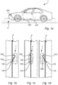
- Fig. 1a illustrates a vehicle in the form of an electrical car 1 operative on an electrical road system comprising an electrically energized path 6.
- the vehicle is here illustrated as an electrical car for exemplary purposes.
- the vehicle may equally well be a hybrid, or plug-in hybrid vehicle comprising an electrical engine, wherein an energy storage pack provides power to an electrical engine of the vehicle for providing propulsion for the electrical, hybrid, or plug-in hybrid vehicle.
- the invention is applicable to any vehicle or electric machine adapted to receive electrical energy from an electrically energized path in the road, the electrically energized path being part of an electrical road system.
- the electric car 1 comprises an electrical energy storage pack (not shown), e.g. a battery pack with a plurality of battery cells.
- the battery pack is arranged to provide power to an electrical engine (not shown) arranged for providing propulsion for the electrical car 1.
- the electrically energized path 6 is configured to provide electrical energy to the vehicle via a charging system comprised in the vehicle 1.
- the electrical charging system may comprise a charging head (se fig. 1b-d ) having thereon arranged a power pick-up device which receives the electrical energy from the electrically energized path 6.
- the vehicle 1 comprises a sensing arrangement for determining a displacement of the vehicle with respect to the electrically energized path 6.
- the sensing arrangement comprises a first sensor 102 and a second sensor 104 spatially separated from the first sensor 102.
- the first sensor 102 is configured to detect the electrically energized path 6 and to determine a first signal indicative of the distance from the first sensor to the electrically energized path 6, and the second sensor 104 is configured to determine the distance from the second sensor to the electrically energized path 6.
- the sensing arrangement further comprises a control unit 108 configured to determine an angular displacement of the vehicle 1 with respect to the electrically energized path 6 based on the first and the second signal.
- the control unit 108 is arranged to communicate with the first sensor 102 and the second sensor 104.
- the first sensor 102 may be an inductive type sensor configured to detect a magnetic field emanating from the electrically energized path 6.
- the electrically energized path 6 may be provided in several different ways, for example, it may be a rail in the road for making electrical contact with a charging head of the charging system om the vehicle, or the electrically energized path 6 may be a power line embedded in the road and instead transferring electrical energy inductively to the charging system of the vehicle 1.
- the second sensor 104 may also be provided in the form of an inductive sensor, but may also be provided as e.g. a capacitive sensor, or a vision based sensor (e.g. a camera).
- the first sensor 102 is here arranged in the rear portion of the vehicle 1 and the second sensor 104 is arranged in the front portion of the vehicle 1.
- the first sensor 102 is arranged on a movable power pickup device 120 configured to track the electrically energized path 6 based on tracking signals provided by the first sensor.
- the power pickup device 120 is configured to receive electrical energy from the electrically energized path 6.
- the tracking of the electrically energized path 6 by the power pickup device 120 is conceptually shown by the sequence of images fig. 1 b-c-d . With this configuration, the distance from the first sensor 102 to the electrically energized path will be at a minimum.
- the measurable minimum distance between the first sensor 102 and the electrically energized path 6 is mainly composed of the distance between the first sensor 102 and the electrically energized path 6 when the first sensor 102 is directly above the electrically energized path 6.
- the difference between the distance from the first sensor to the electrically energized path 6 and the distance from the second sensor 104 and the electrically energized path 6 will be mainly defined by the distance between the second sensor 104 and the electrically energized path 6.
- the moveable power pick-up device 120 is connected to the vehicle 1 with a linkage arm 109 which is movable with respect to the vehicle 1, e.g. rotatable about a pivot point, or laterally displaceable (not shown) such that the power pick-up device 120 may be aligned with the electrically energized path 6.
- Fig. 2a-b conceptually illustrating determining an angular displacement of the vehicle 1 with respect to the electrically energized path 6.
- the vehicle 1 is relatively aligned with the electrically energized path 6 and in fig. 2b , the vehicle is angularly displaced an angle v from the electrically energized path 6.
- a first sensor 102 and the second sensor 104 are spatially separated a distance 106, and the second sensor 104 is arranged in front of the first sensor 102 where the vehicle heading indicates the front of the vehicle 1.
- the vehicle heading is indicated by the arrow 112.
- a control unit (not shown in fig. 2a-b , but see fig. 1 ) is configured to read a first and a second signal from the first and the second sensor, respectively.
- the signals are indicative of the distance from the first 102 and the second sensor 104 and the electrically energized path 6, respectively.
- the angular deviation v may be determined.
- both the first signal and the second signal will indicate a minimum distance between the first sensor 102 and the electrically energized path 6 and between the second sensor 104 and the electrically energized path 6. In this case, the vehicle may be determined to be on course with the electrically energized path 6.
- the first signal will indicate a minimum distance between the first sensor 102 and the electrically energized path 6.
- the second signal will be indicative of a distance x from the second sensor 104 to the electrically energized path 6. Comparing the first signal to the second signal would thus indicate a difference in the distances.
- Such a comparison may be performed in several ways, e.g. through a ratio between the first and the second signal, or through a subtraction. Based on the comparison a decision may be taken by the control unit to provide a control signal to a vehicle control unit. As an example, if the comparison is a subtraction of the distances (e.g.
- a control signal sent to the vehicle control unit is adapted to cause a correction of the trajectory of the vehicle to reduce the angular displacement v.
- the angle v may be determined from knowledge of the distance 106 between the sensors 104 and 102, and the difference between the measured distance from the first sensor to the electrically energized path 6 and the measured distance from the second sensor 104 to the electrically energized path 6, or vice versa, together with trigonometric formulas known to the skilled person.
- first sensor and the second sensor are aligned along an axis 110 parallel with a front-to-rear axis 110 of the vehicle.
- the first and the second distance may preferably indicate the minimum distance from the respective sensor to the electrically energized path 6.
- FIG. 3 schematically shows a vehicle 1 driving on a road having an integrated electrically energized path 6.
- the vehicle 1 is equipped with a sensing arrangement for determining an angular displacement of the vehicle with respect to the electrically energized path 6, the arrangement comprising the first sensor 102 and the second sensor 104.
- the vehicle is driving along the road 106 and is relatively well aligned with the electrically energized path 6, in other words, the distance from the first sensor 102 to the electrically energized path 6 is relatively similar to the distance from the second sensor 104 to the electrically energized path 6, preferable, both the distances are at a minimum distance.
- the distance from the second sensor 104 to the electrically energized path 6 is now the distance x, i.e. larger than zero.
- a comparison between the first distance and the second distance will result in a difference between the distances. If this difference (e.g. a subtraction between the first distance and the second distance) exceeds a threshold value, a control signal may be provided from the control unit to a vehicle control unit such that a further action may be executed. In this case, the further action is to steer "left" such that the vehicle 1 gets back on track.
- the distance from the first sensor 102 to the electrically energized path 6 is relatively similar to the distance from the second sensor 104 to the electrically energized path 6, preferably, both the distances are close to the respective minimum distance. In other words, the vehicle is again back on track.
- phase-shift detection scheme a different phase of a response signal from the electrically energized path 6, or from a signal cable associated with the electrically energized path is measured depending which side (e.g. left-right) of the electrically energized path 6 that the sensor is located. For example, one a first side the phase may be "0°” and on the opposite side of the electrically energized path 6 the phase may be "180°".
- the first signal and the second signal indicative of the distance between the first 102 and second 104 sensor and the electrically energized path 6 may be based on a received signal from the electrically energized path or from a transmitter device (e.g. an antenna transmitting an RF-signal, not shown) associated with the electrically energized path 6.
- the strength of the received first signal is indicative of the distance between the first sensor and the electrically energized path.
- the strength of the received second signal is indicative of the distance between the second sensor 104 and the electrically energized path 6.
- Fig. 4 conceptually illustrates a sensing arrangement 100 according to an embodiment of the invention.
- the sensing arrangement comprises a first sensor 102 configured to determine first signal indicative of a distance from the first sensor 102 to an electrically energized path associated with an electrical road system.
- the signals are provided to a control unit 108 which may be an ECU (electrical control unit) of the vehicle.
- the control unit evaluates the signals and determines an angular displacement of the vehicle with respect to the electrically energized path.
- control unit 108 is configured to provide a control signal to a vehicle control unit 200 which may be part of the vehicles steering control system 200.
- the control signal may include an indication to execute a further action for controlling the vehicle for example to reduce the angular displacement to get back on course.
- the control signal may for example include a trajectory correction such that the vehicle control unit 200 can take the appropriate action (e.g. steering) to correct the trajectory of the vehicle.
- Fig. 5 is a flow-chart of method steps according to embodiments of the invention.
- a first distance between the first sensor and the electrically energized path is determined.
- a second distance is determined between the second sensor and the electrically energized path.
- an angular displacement of the vehicle with respect to the electrically energized path is determined S506.
- Fig. 6 is a flow chart conceptually illustrating embodiments of the invention. If the vehicle is parallel to the electrically energized path and the first and the second sensor both determine the same distance to the electrically energized path S603, the control unit (108) may evaluate S604 the first signal and the second signal indicative of the distances and determine that no action is required S605. However, in a situation where the vehicle is not parallel to the electrically energized path the difference between the distances (indicated by the first and the second signal) is not zero S606. The control unit (108) performs an evaluation S607 and it is determined that the difference exceeds a threshold value S608, a control signal is provided to the relevant vehicle systems S609, such as steering control or braking control systems. If the difference did not exceed the threshold value in S608, no action is performed S605.
- a threshold value S608 such as steering control or braking control systems.
- a control unit may include a microprocessor, microcontroller, programmable digital signal processor or another programmable device.
- the control unit 108, 200 may comprise electronic circuits and connections (not shown) as well as processing circuitry (not shown) such that the control unit can communicate with different parts of the vehicle such as the brakes, suspension, driveline, in particular an electrical engine, an electric machine, a clutch, and a gearbox in order to at least partly operate the vehicle.
- the control unit may comprise modules in either hardware or software, or partially in hardware or software and communicate using known transmission buses such as CAN-bus and/or wireless communication capabilities.
- the processing circuitry may be a general purpose processor or a specific processor.
- the control unit may comprise a non-transistory memory for storing computer program code and data upon. Thus, the skilled addressee realizes that the control unit may be embodied by many different constructions.
- control functionality of the present disclosure may be implemented using existing computer processors, or by a special purpose computer processor for an appropriate system, incorporated for this or another purpose, or by a hardwire system.
- Embodiments within the scope of the present disclosure include program products comprising machine-readable medium for carrying or having machine-executable instructions or data structures stored thereon.
- Such machine-readable media can be any available media that can be accessed by a general purpose or special purpose computer or other machine with a processor.
- machine-readable media can comprise RAM, ROM, EPROM, EEPROM, CD-ROM or other optical disk storage, magnetic disk storage or other magnetic storage devices, or any other medium which can be used to carry or store desired program code in the form of machine-executable instructions or data structures and which can be accessed by a general purpose or special purpose computer or other machine with a processor.
- a network or another communications connection either hardwired, wireless, or a combination of hardwired or wireless
- any such connection is properly termed a machine-readable medium.
- Machine-executable instructions include, for example, instructions and data which cause a general purpose computer, special purpose computer, or special purpose processing machines to perform a certain function or group of functions.
Landscapes
- Engineering & Computer Science (AREA)
- Transportation (AREA)
- Mechanical Engineering (AREA)
- Power Engineering (AREA)
- Physics & Mathematics (AREA)
- Life Sciences & Earth Sciences (AREA)
- Sustainable Development (AREA)
- Sustainable Energy (AREA)
- Automation & Control Theory (AREA)
- General Physics & Mathematics (AREA)
- Radar, Positioning & Navigation (AREA)
- Remote Sensing (AREA)
- Aviation & Aerospace Engineering (AREA)
- Electromagnetism (AREA)
- Multimedia (AREA)
- Theoretical Computer Science (AREA)
- Electric Propulsion And Braking For Vehicles (AREA)
Description
- The invention relates to a sensing arrangement and a method for providing electrical energy to a vehicle driving on an electrical road system.
- The invention can be applied in any type of electrical or hybrid vehicles, such as trucks, buses, cars and construction equipment operable on an electrical road system. Although the invention will be described with respect to a truck, the invention is thus not restricted to this particular vehicle.
- Electric and hybrid vehicles are becoming a more common sight on roads worldwide, and they offer a more environmentally friendly alternative to the typical combustions engine driven vehicles. Although the electric and hybrid vehicles provides excellent solutions for reducing the impact of transportation on the environment, the need for recharging the batteries in the case of electric vehicles still partly limits the usability.
- Recently, electric road systems have been investigated on which the vehicles may charge its batteries while driving. This may provide increased driving range for electrical vehicles, at least on roads which have an associated electrical road system. In such an electric road system, a power line may be integrated in the road such that the vehicle may contact the power line while travelling on the road.
-
KR20140034092 KR20140034092 KR20140034092 -
US2005/0103545 discloses a device for inductively supplying power and guiding a mobile object and suffer from similar drawbacks asKR20140034092 US4227595 discloses a current transmitting system for electrical vehicle andUS4742283 discloses a guidance system for inductively coupled vehicles. - An object of the invention is to provide a sensing arrangement for providing electrical energy to a vehicle driving on an electrical road system with improved capabilities for alignment of the vehicle with relation to a charging surface of the electrical road system.
- The object is achieved by a sensing arrangement according to
claim 1. - According to a first aspect of the invention, there is provided a sensing arrangement for determining a displacement of a vehicle with respect to an electrical road system, the vehicle being adapted for driving on said electrical road system comprising an electrically energized path for providing electrical energy to said vehicle, wherein said sensing arrangement comprises: a first sensor configured to detect said electrically energized path and to determine a first signal indicative of the distance between the first sensor and the electrically energized path; a second sensor configured to determine a second signal indicative of the distance between the second sensor and the electrically energized path, wherein said second sensor is located in a pre-defined location of said vehicle spatially separated a distance from said first sensor in a front-rear direction of the vehicle, and a control unit connected with said first sensor and said second sensor, said control unit being configured to determine an angular displacement of the vehicle with respect to said electrically energized path based on the first signal, the second signal and said distance between the first sensor and said second sensor.
- By the provision of a sensing arrangement which comprises a first sensor and a second sensor which are spatially separated in a front-rear direction of the vehicle, an advantageous way of determining a vehicle heading is provided which enables to predict a future offset of the vehicle with respect to the electrically energized path. In other words, by determining the distance from two points on the vehicle, as provided by the locations of the first and the second sensor, and by having knowledge of the distance between the first and the second sensors, one can detect any non-parallel movement of the vehicle with respect to the electrically energized path.
- The present invention is thus based on the realization that by using two spatially separated sensors arranged on the vehicle, both the lateral displacement and the vehicle heading of the vehicle with respect to the electrically energized path may be determined.
- This advantageously provides the possibility to take appropriate action for the vehicle depending on a predicted future offset of the vehicle with respect to the electrical energized path.
- The electrically energized path may be any type of path which is capable of transferring electrical charge from a power source associated with the electrical road system to the vehicle. For example, the charging surface may be a visible rail integrated in the road, or a non-visible power line embedded in the road. The electrical charge may for example be used for charging an energy storage device on-board the vehicle.
- The first sensor and the second sensor are arranged a known distance from each other in the front-rear direction of the vehicle. Further, a known lateral displacement is also allowable and may be taken into account for in the "known distance".
- The first sensor may be arranged as a rear sensor on the vehicle and the second sensor may be arranged as a front sensor on the vehicle.
- It should be understood that the first sensor and the second sensor are not arranged to intercept with the electrically energized path. In other words, the minimum distance between the first (second) sensor and the electrically energized path is given by the distance between the first (second) sensor and the electrically energized path when the first (second) sensor is directly above the electrically energized path. In other words, the minimum distances are the distance along an axis substantially orthogonal to the electrically energized path and intercepting with the first (second) sensor. It should be understood that the above applies also to the relationship between the second sensor and the electrically energized path.
- The first sensor may directly detect the electrically energized path as part of a charging device of the vehicle configured to track the electrically energized path for enabling charging of an electrical energy storage unit of the vehicle. The second sensor may either track a mark of some kind which provides a measure indicative of the distance between the second sensor and the electrically energized path, or alternatively the second sensor detects the electrically energized path directly similar to the first sensor. Thus, the second sensor is advantageously not limited to detecting the electrically energized path directly.
- According to one embodiment, the control unit may be configured to compare the first signal and the second signal to each other, and based on the comparison provide a control signal to execute a further action for controlling the vehicle, the control signal being provided to a vehicle control unit. Hereby controlling of the vehicle by executing the further action advantageously provides for controlling the vehicle in situations which may otherwise cause a hazardous situation which may lead to an accident. For example, controlling and/or correcting the position of the vehicle on the road are advantageously possible by providing the appropriate control signal based on the comparison.
- The control signal may for example be indicative of a trajectory correction for the vehicle, wherein the vehicle control unit is configured to correct the trajectory for the vehicle according to the control signal.
- Further, the comparison may be based on a subtraction of the first signal from the second signal or a subtraction of the second signal from the first signal, the subtraction providing an indication of the difference in distance to the electrically energized path from the first sensor and the second sensor, wherein if the difference in distance exceeds a threshold value, the control unit is configured to provide the control signal to a vehicle control unit for executing the further action. Hereby, the control unit is advantageously configured to provide the control signal for a further action only if a threshold value is exceeded. Accordingly, unnecessary actions executed by the vehicle control unit can be avoided.
- According to one embodiment, the first sensor and the second sensor are arranged aligned along an axis parallel with a front-to-rear axis of the vehicle. A front-rear axis should be understood as an axis substantially parallel with the vehicle heading.
- The first sensor and the second sensor may be inductive sensors arranged to detect a magnetic field transmitted from the path. Hereby, an advantage is provided by using a non-vision based sensor technique. Non-vision sensing is less costly, less sensitive to weather conditions, and it may reduce the computational load on the control units of the vehicle otherwise needed for visual recognition of the electrical energized path. An inductive sensor may sense a magnetic field emanating from the electrical energized path.
- Alternatively the second sensor may be one of a capacitive, inductive, or optical sensor.
- According to a further embodiment, the first sensor is arranged on a movable power pickup device configured to track the electrically energized path based on tracking signals provided by the first sensor, the power pickup device being configured to receive electrical energy from the electrically energized path. This advantageously provides for using an already existing sensor arranged on the power pick-up device as the first sensor. In this case, the relative locations between the first sensor and the second sensor may be determined by using knowledge of the power pick up device geometry and a position sensor which may determine the present orientation of the power pick up device with respect to the second sensor. The position sensor may be part of an actuator module controlling the motion of the power pick-up device.
- The power pick-up device may for example be connected to the vehicle with linkage arm, whereby the linkage arm is movable in a controllable manner such that the power pick-up device may be arranged in relation to the electrically energized path such that electrical energy may be transferred from the electrically energized path to the power pick-up device. The power pick-up device may for example be arranged aligned with the electrically energized path.
- The first signal and the second signal indicative of the distance between the first and second sensor and the electrically energized path may be based on a received signal from the electrically energized path or from a transmitter device (e.g. an antenna transmitting an RF-signal) associated with the electrically energized path. The strength of the respective received signal is indicative of the distance between the first and second sensor and the electrically energized path, respectively. Furthermore, the phase of the signal is indicative of on which side of the electrically energized path the first and/or second sensor is located. For example, if the phase is determined to be "0°", this may indicate that the respective sensor is on the "left" side of the electrically energized path, and if the phase is determined to be "180°" may indicate that the respective sensor is on the "right" hand side of the electrically energized path. The transmitter device may be a loop structure (e.g. a wire or signal cable) emitting a magnetic field (e.g. an RF-signal) and the first and second sensor may comprise antennas to detect the magnetic field. As the first (or second) sensor approaches the transmitter device from one side, the signal strength increases, when the first (or second) sensor is directly above the loop, the phase of the induced signal in the receiver antenna of the first (or second) sensor will change by 180 degrees. As the sensor moves away from the transmitter device the signal strength decreases but with maintained phase (180 degrees shifted). Thus, from the phase, it can be determined on which side of the electrically energized path the first (or second) second is located.
- There is further provided according to the invention, a vehicle comprising: a sensing arrangement according to the first aspect and embodiments thereof.
- The vehicle may be an electrical, hybrid, or plug-in hybrid vehicle comprising an electrical engine, wherein an energy storage pack provides power to an electrical engine of the vehicle for providing propulsion for the electrical, hybrid, or plug-in hybrid vehicle. The invention is applicable to any vehicle or electric machine adapted to receive electrical energy from an electrically energized path in the road, the electrically energized path being part of an electrical road system.
- The object is also achieved by a method according to claim 11.
- According to second aspect of the invention, there is provided a method for determining a vehicle heading, the vehicle adapted for driving on an electrical road system comprising an electrically energized path for providing electrical energy to the vehicle, the vehicle comprising a first sensor configured to detect the electrically energized path and to determine a first signal indicative of the distance between the first sensor and the electrically energized path; a second sensor configured to determine a second signal indicative of the distance between the second sensor and the electrically energized path, wherein said second sensor is located in a pre-defined location of said vehicle spatially separated a distance from said first sensor in a front-rear direction of the vehicle, wherein said method comprises: determining a first distance between the first sensor and the electrically energized path; determining a second distance between the second sensor and the electrically energized path; and determining an angular displacement of the vehicle with respect to the electrically energized path based on the first signal, the second signal and the distance between the first sensor and the second sensor.
- According to one embodiment, the method may comprise: comparing the first distance and the second distance to each other, and based on the comparison, executing a further action for controlling the vehicle.
- The step of comparing may comprise determining a difference between the first distance and the second distance, wherein if the difference in distance exceeds a threshold value, executing the further action.
- The step of executing the further action may comprise correcting a trajectory for the vehicle based on the angular displacement.
- Effects and features of the second aspect of the invention are largely analogous to those described above in connection with the first aspect.
- Furthermore, there is provided a computer program comprising program code means for performing the steps of any of the embodiments of the second aspect when the program is run on a computer.
- Furthermore, there is provided a computer readable medium carrying a computer program comprising program code means for performing the steps of any of the embodiments of the second aspect when the program product is run on a computer.
- Additionally, there is provided a control unit for determining a vehicle heading, the vehicle adapted for driving on an electrical road system comprising an electrically energized path for providing electrical energy to the vehicle, the vehicle comprising a first sensor configured to detect the electrically energized path and to determine a first signal indicative of the distance between the first sensor and the electrically energized path; and a second sensor configured to determine a second signal indicative of the distance between the second sensor and the electrically energized path, wherein said second sensor is located in a pre-defined location of said vehicle spatially separated a distance from said first sensor in a front-rear direction of the vehicle, the control unit being configured to perform the steps of any of the embodiments of the second aspect.
- Further features of, and advantages with, the present invention will become apparent when studying the appended claims and the following description. The skilled person realize that different features of the present invention may be combined to create embodiments other than those described in the following, without departing from the scope of the present invention.
- With reference to the appended drawings, below follows a more detailed description of embodiments of the invention cited as examples.
- In the drawings:
-
Fig. 1a-d is a vehicle in the form of a car according to example embodiments of the invention; -
Fig. 2a-b is a conceptual drawing of embodiments of the invention; -
Fig. 3 conceptually illustrates an embodiment of the invention in an operative situation; -
Fig. 4 conceptually illustrates a sensing arrangement according to an embodiment of the invention. -
Fig. 5 is a flow-chart of method steps according to embodiments of the invention; and -
Fig. 6 is a flow-chart of method steps according to embodiments of the invention; - The present invention will now be described more fully hereinafter with reference to the accompanying drawings, in which exemplary embodiments of the invention are shown. The invention may, however, be embodied in many different forms and should not be construed as limited to the embodiments set forth herein; rather, these embodiments are provided for thoroughness and completeness. The skilled person will recognize that many changes and modifications may be made within the scope of the appended claims. Like reference character refer to like elements throughout the description.
-
Fig. 1a illustrates a vehicle in the form of anelectrical car 1 operative on an electrical road system comprising an electrically energizedpath 6. The vehicle is here illustrated as an electrical car for exemplary purposes. The vehicle may equally well be a hybrid, or plug-in hybrid vehicle comprising an electrical engine, wherein an energy storage pack provides power to an electrical engine of the vehicle for providing propulsion for the electrical, hybrid, or plug-in hybrid vehicle. The invention is applicable to any vehicle or electric machine adapted to receive electrical energy from an electrically energized path in the road, the electrically energized path being part of an electrical road system. - The
electric car 1 comprises an electrical energy storage pack (not shown), e.g. a battery pack with a plurality of battery cells. The battery pack is arranged to provide power to an electrical engine (not shown) arranged for providing propulsion for theelectrical car 1. The electrically energizedpath 6 is configured to provide electrical energy to the vehicle via a charging system comprised in thevehicle 1. The electrical charging system may comprise a charging head (sefig. 1b-d ) having thereon arranged a power pick-up device which receives the electrical energy from the electrically energizedpath 6. Thevehicle 1 comprises a sensing arrangement for determining a displacement of the vehicle with respect to the electrically energizedpath 6. The sensing arrangement comprises afirst sensor 102 and asecond sensor 104 spatially separated from thefirst sensor 102. Thefirst sensor 102 is configured to detect the electrically energizedpath 6 and to determine a first signal indicative of the distance from the first sensor to the electrically energizedpath 6, and thesecond sensor 104 is configured to determine the distance from the second sensor to the electrically energizedpath 6. The sensing arrangement further comprises acontrol unit 108 configured to determine an angular displacement of thevehicle 1 with respect to the electrically energizedpath 6 based on the first and the second signal. Thecontrol unit 108 is arranged to communicate with thefirst sensor 102 and thesecond sensor 104. - The
first sensor 102 may be an inductive type sensor configured to detect a magnetic field emanating from the electrically energizedpath 6. The electrically energizedpath 6 may be provided in several different ways, for example, it may be a rail in the road for making electrical contact with a charging head of the charging system om the vehicle, or the electrically energizedpath 6 may be a power line embedded in the road and instead transferring electrical energy inductively to the charging system of thevehicle 1. Thesecond sensor 104 may also be provided in the form of an inductive sensor, but may also be provided as e.g. a capacitive sensor, or a vision based sensor (e.g. a camera). Thefirst sensor 102 is here arranged in the rear portion of thevehicle 1 and thesecond sensor 104 is arranged in the front portion of thevehicle 1. - Furthermore, with reference to
fig. 1b-d , thefirst sensor 102 is arranged on a movablepower pickup device 120 configured to track the electrically energizedpath 6 based on tracking signals provided by the first sensor. Thepower pickup device 120 is configured to receive electrical energy from the electrically energizedpath 6. The tracking of the electrically energizedpath 6 by thepower pickup device 120 is conceptually shown by the sequence of imagesfig. 1 b-c-d . With this configuration, the distance from thefirst sensor 102 to the electrically energized path will be at a minimum. The measurable minimum distance between thefirst sensor 102 and the electrically energizedpath 6 is mainly composed of the distance between thefirst sensor 102 and the electrically energizedpath 6 when thefirst sensor 102 is directly above the electrically energizedpath 6. In other words, the difference between the distance from the first sensor to the electrically energizedpath 6 and the distance from thesecond sensor 104 and the electrically energizedpath 6 will be mainly defined by the distance between thesecond sensor 104 and the electrically energizedpath 6. The moveable power pick-updevice 120 is connected to thevehicle 1 with alinkage arm 109 which is movable with respect to thevehicle 1, e.g. rotatable about a pivot point, or laterally displaceable (not shown) such that the power pick-updevice 120 may be aligned with the electrically energizedpath 6. - Now turning to
Fig. 2a-b conceptually illustrating determining an angular displacement of thevehicle 1 with respect to the electrically energizedpath 6. Infig. 2a , thevehicle 1 is relatively aligned with the electrically energizedpath 6 and infig. 2b , the vehicle is angularly displaced an angle v from the electrically energizedpath 6. In bothFig. 2a-b afirst sensor 102 and thesecond sensor 104 are spatially separated adistance 106, and thesecond sensor 104 is arranged in front of thefirst sensor 102 where the vehicle heading indicates the front of thevehicle 1. The vehicle heading is indicated by thearrow 112. - A control unit (not shown in
fig. 2a-b , but seefig. 1 ) is configured to read a first and a second signal from the first and the second sensor, respectively. The signals are indicative of the distance from the first 102 and thesecond sensor 104 and the electrically energizedpath 6, respectively. Based on the signals, the angular deviation v may be determined. Turning first tofig. 2a , both the first signal and the second signal will indicate a minimum distance between thefirst sensor 102 and the electrically energizedpath 6 and between thesecond sensor 104 and the electrically energizedpath 6. In this case, the vehicle may be determined to be on course with the electrically energizedpath 6. - Turning to
fig. 2b , the first signal will indicate a minimum distance between thefirst sensor 102 and the electrically energizedpath 6. However, the second signal will be indicative of a distance x from thesecond sensor 104 to the electrically energizedpath 6. Comparing the first signal to the second signal would thus indicate a difference in the distances. Such a comparison may be performed in several ways, e.g. through a ratio between the first and the second signal, or through a subtraction. Based on the comparison a decision may be taken by the control unit to provide a control signal to a vehicle control unit. As an example, if the comparison is a subtraction of the distances (e.g. the signals), and the difference between the signals exceeds a threshold value, it is indicative that the vehicle is not on the same course as the electrically energizedpath 6. Accordingly, a control signal sent to the vehicle control unit is adapted to cause a correction of the trajectory of the vehicle to reduce the angular displacement v. The angle v may be determined from knowledge of thedistance 106 between thesensors path 6 and the measured distance from thesecond sensor 104 to the electrically energizedpath 6, or vice versa, together with trigonometric formulas known to the skilled person. In addition, the first sensor and the second sensor are aligned along anaxis 110 parallel with a front-to-rear axis 110 of the vehicle. The first and the second distance may preferably indicate the minimum distance from the respective sensor to the electrically energizedpath 6. - Now with reference to
Fig. 3 showing an exemplary operative situation for an embodiment of the invention.Fig. 3 schematically shows avehicle 1 driving on a road having an integrated electrically energizedpath 6. As described with reference tofig. 1a-d , thevehicle 1 is equipped with a sensing arrangement for determining an angular displacement of the vehicle with respect to the electrically energizedpath 6, the arrangement comprising thefirst sensor 102 and thesecond sensor 104. First (A), the vehicle is driving along theroad 106 and is relatively well aligned with the electrically energizedpath 6, in other words, the distance from thefirst sensor 102 to the electrically energizedpath 6 is relatively similar to the distance from thesecond sensor 104 to the electrically energizedpath 6, preferable, both the distances are at a minimum distance. A moment later, the vehicle has travelled to a second position (B), at which moment the distance from thefirst sensor 102 to the electrically energizedpath 6 still is at or close to the minimum distance. However, the distance from thesecond sensor 104 to the electrically energizedpath 6 is now the distance x, i.e. larger than zero. In other words, a comparison between the first distance and the second distance will result in a difference between the distances. If this difference (e.g. a subtraction between the first distance and the second distance) exceeds a threshold value, a control signal may be provided from the control unit to a vehicle control unit such that a further action may be executed. In this case, the further action is to steer "left" such that thevehicle 1 gets back on track. At a yet later moment (C), the distance from thefirst sensor 102 to the electrically energizedpath 6 is relatively similar to the distance from thesecond sensor 104 to the electrically energizedpath 6, preferably, both the distances are close to the respective minimum distance. In other words, the vehicle is again back on track. - In order to determine that the vehicle is parallel to the electrically energized
path 6, it is also advantageous to know on which side of the electrically energizedpath 6 that the first 102 and thesecond sensor 104 are located. This may be performed in several ways, for example by using a camera as thesecond sensor 104, or by implementing a phase-shift detection scheme. With the phase-shift detection scheme, a different phase of a response signal from the electrically energizedpath 6, or from a signal cable associated with the electrically energized path is measured depending which side (e.g. left-right) of the electrically energizedpath 6 that the sensor is located. For example, one a first side the phase may be "0°" and on the opposite side of the electrically energizedpath 6 the phase may be "180°". - The first signal and the second signal indicative of the distance between the first 102 and second 104 sensor and the electrically energized
path 6 may be based on a received signal from the electrically energized path or from a transmitter device (e.g. an antenna transmitting an RF-signal, not shown) associated with the electrically energizedpath 6. The strength of the received first signal is indicative of the distance between the first sensor and the electrically energized path. Similarly, the strength of the received second signal is indicative of the distance between thesecond sensor 104 and the electrically energizedpath 6. -
Fig. 4 conceptually illustrates asensing arrangement 100 according to an embodiment of the invention. The sensing arrangement comprises afirst sensor 102 configured to determine first signal indicative of a distance from thefirst sensor 102 to an electrically energized path associated with an electrical road system. There is further asecond sensor 104 configured to determine second signal indicative of a distance from thesecond sensor 104 to the electrically energized path. The signals are provided to acontrol unit 108 which may be an ECU (electrical control unit) of the vehicle. The control unit evaluates the signals and determines an angular displacement of the vehicle with respect to the electrically energized path. Furthermore, in some embodiments, thecontrol unit 108 is configured to provide a control signal to avehicle control unit 200 which may be part of the vehicles steeringcontrol system 200. The control signal may include an indication to execute a further action for controlling the vehicle for example to reduce the angular displacement to get back on course. The control signal may for example include a trajectory correction such that thevehicle control unit 200 can take the appropriate action (e.g. steering) to correct the trajectory of the vehicle. -
Fig. 5 is a flow-chart of method steps according to embodiments of the invention. In a first step S502, a first distance between the first sensor and the electrically energized path is determined. Subsequently, S504 a second distance is determined between the second sensor and the electrically energized path. Based on the first signal, the second signal and the distance between the first sensor and the second sensor, an angular displacement of the vehicle with respect to the electrically energized path is determined S506. -
Fig. 6 is a flow chart conceptually illustrating embodiments of the invention. If the vehicle is parallel to the electrically energized path and the first and the second sensor both determine the same distance to the electrically energized path S603, the control unit (108) may evaluate S604 the first signal and the second signal indicative of the distances and determine that no action is required S605. However, in a situation where the vehicle is not parallel to the electrically energized path the difference between the distances (indicated by the first and the second signal) is not zero S606. The control unit (108) performs an evaluation S607 and it is determined that the difference exceeds a threshold value S608, a control signal is provided to the relevant vehicle systems S609, such as steering control or braking control systems. If the difference did not exceed the threshold value in S608, no action is performed S605. - A control unit may include a microprocessor, microcontroller, programmable digital signal processor or another programmable device. Thus, the
control unit - The control functionality of the present disclosure may be implemented using existing computer processors, or by a special purpose computer processor for an appropriate system, incorporated for this or another purpose, or by a hardwire system. Embodiments within the scope of the present disclosure include program products comprising machine-readable medium for carrying or having machine-executable instructions or data structures stored thereon. Such machine-readable media can be any available media that can be accessed by a general purpose or special purpose computer or other machine with a processor. By way of example, such machine-readable media can comprise RAM, ROM, EPROM, EEPROM, CD-ROM or other optical disk storage, magnetic disk storage or other magnetic storage devices, or any other medium which can be used to carry or store desired program code in the form of machine-executable instructions or data structures and which can be accessed by a general purpose or special purpose computer or other machine with a processor. When information is transferred or provided over a network or another communications connection (either hardwired, wireless, or a combination of hardwired or wireless) to a machine, the machine properly views the connection as a machine-readable medium. Thus, any such connection is properly termed a machine-readable medium. Combinations of the above are also included within the scope of machine-readable media. Machine-executable instructions include, for example, instructions and data which cause a general purpose computer, special purpose computer, or special purpose processing machines to perform a certain function or group of functions.
- Although the figures may show a sequence the order of the steps may differ from what is depicted. Also two or more steps may be performed concurrently or with partial concurrence. Such variation will depend on the software and hardware systems chosen and on designer choice. All such variations are within the scope of the disclosure. Likewise, software implementations could be accomplished with standard programming techniques with rule based logic and other logic to accomplish the various connection steps, processing steps, comparison steps and decision steps. Additionally, even though the invention has been described with reference to specific exemplifying embodiments thereof, many different alterations, modifications and the like will become apparent for those skilled in the art.
- It is to be understood that the present invention is not limited to the embodiments described above and illustrated in the drawings; rather, the skilled person will recognize that many changes and modifications may be made within the scope of the appended claims.
Claims (16)
- A sensing arrangement (100) for determining a displacement of a vehicle (1) with respect to an electrical road system, the vehicle (1) being adapted for driving on said electrical road system comprising an electrically energized path (6) for providing electrical energy to said vehicle, wherein said sensing arrangement comprises:a first sensor (102) configured to detect said electrically energized path and to determine a first signal indicative of the distance between the first sensor and the electrically energized path;a second sensor (104) configured to determine a second signal indicative of the distance between the second sensor and the electrically energized path, wherein said second sensor is located in a pre-defined location of said vehicle spatially separated a distance (106) from said first sensor in a front-rear direction of the vehicle, anda control unit (108) connected with said first sensor and said second sensor, said control unit being configured to determine an angular displacement of the vehicle with respect to said electrically energized path based on the first signal, the second signal and said distance between the first sensor and said second sensor, wherein the sensing arrangement is characterized in that:
said first sensor is arranged on a movable power pickup device (120) configured to track the electrically energized path based on tracking signals provided by said first sensor, wherein movable power pickup device is connected to the vehicle with a linkage arm (109) which is movable with respect to the vehicle such that the power pickup device is able to align with the electrically energized path said power pickup device being configured to receive electrical energy from said electrically energized path. - The sensing arrangement according to claim 1, characterized in that said second sensor is configured to detect said electrically energized path.
- The sensing arrangement according to any one of the preceding claims, characterized in that said control unit is configured to compare said first signal and said second signal to each other, and based on the comparison provide a control signal to execute a further action for controlling the vehicle, said control signal being provided to a vehicle control unit (200).
- The sensing arrangement according to claim 3, characterized in that said comparison is based on a subtraction of said first signal from said second signal or a subtraction of said second signal from said first signal, said subtraction providing an indication of the difference in distance to the electrically energized path from the first sensor and the second sensor, wherein if said difference in distance exceeds a threshold value, said control unit is configured to provide said control signal to a vehicle control unit for executing said further action.
- The sensing arrangement according to claim 4 or 5, characterized in that said control signal is indicative of a trajectory correction for the vehicle, wherein said vehicle control unit is configured to correct the trajectory for the vehicle according to the control signal.
- The sensing arrangement according to any one of the preceding claims, characterized in that said first sensor and said second sensor are aligned along an axis parallel with a front-to-rear axis of the vehicle.
- The sensing arrangement according to any one of the preceding claims, characterized in that said first sensor and said second sensor are inductive sensors arranged to detect a magnetic field transmitted from said electrically energized path.
- The sensing arrangement according to any one of claims 1 to 6, characterized in that said second sensor is one of a capacitive, inductive, or optical sensor.
- A vehicle (1) comprising:
a sensing arrangement (100) according to any one of claims 1 to 8. - A method for determining a vehicle heading, said vehicle adapted for driving on an electrical road system comprising an electrically energized path for providing electrical energy to said vehicle, said vehicle comprising:a first sensor (102) configured to detect said electrically energized path and to determine a first signal indicative of the distance between the first sensor and the electrically energized path; anda second sensor (104) configured to determine a second signal indicative of the distance between the second sensor and the electrically energized path, wherein said second sensor is located in a pre-defined location of said vehicle spatially separated a distance (106) from said first sensor in a front-rear direction of the vehicle, whereinsaid first sensor is arranged on a movable power pickup device (120) configured to track the electrically energized path based on tracking signals provided by said first sensor, said power pickup device being configured to receive electrical energy from said electrically energized path.wherein said method is characterized by:- determining (S502) a first distance between the first sensor and the electrically energized path;- determining (S504) a second distance between the second sensor and the electrically energized path; and- determining (S506) an angular displacement of the vehicle with respect to said electrically energized path based on the first signal, the second signal and said distance between the first sensor and said second sensor.
- The method according to claim 10, characterized by:- comparing said first distance and said second distance to each other, and- based on the comparison, executing a further action for controlling the vehicle.
- The method according to claim 11, characterized in that said step of comparing comprises determining a difference between said first distance and said second distance, wherein if said difference in distance exceeds a threshold value, executing said further action.
- The method according to claim 12, characterized in that executing said further action comprising correcting a trajectory for said vehicle based on the angular displacement.
- A computer program comprising program code means for performing the steps of any of claims 10-13 when said program is run on a computer.
- A computer readable medium carrying a computer program comprising program code means for performing the steps of any of claims 10-13 when said program product is run on a computer.
- A control unit for determining a vehicle heading, said vehicle adapted for driving on an electrical road system comprising an electrically energized path for providing electrical energy to said vehicle, said vehicle comprising a sensing arrangement according to claim 1, the control unit being configured to perform the steps of the method according to any of claims 10-13.
Applications Claiming Priority (1)
| Application Number | Priority Date | Filing Date | Title |
|---|---|---|---|
| PCT/EP2017/053258 WO2018149478A1 (en) | 2017-02-14 | 2017-02-14 | A sensing arrangement for determining a displacement of a vehicle with respect to an electrical road system |
Publications (2)
| Publication Number | Publication Date |
|---|---|
| EP3583480A1 EP3583480A1 (en) | 2019-12-25 |
| EP3583480B1 true EP3583480B1 (en) | 2021-09-29 |
Family
ID=58057121
Family Applications (1)
| Application Number | Title | Priority Date | Filing Date |
|---|---|---|---|
| EP17705841.9A Active EP3583480B1 (en) | 2017-02-14 | 2017-02-14 | A sensing arrangement for determining a displacement of a vehicle with respect to an electrical road system |
Country Status (4)
| Country | Link |
|---|---|
| US (1) | US11526176B2 (en) |
| EP (1) | EP3583480B1 (en) |
| CN (1) | CN110290970B (en) |
| WO (1) | WO2018149478A1 (en) |
Families Citing this family (4)
| Publication number | Priority date | Publication date | Assignee | Title |
|---|---|---|---|---|
| US11541768B2 (en) * | 2017-02-15 | 2023-01-03 | Volvo Truck Corporation | Arrangement and method for active alignment control of a contact element |
| CN111409632B (en) * | 2018-12-19 | 2021-09-10 | 长沙智能驾驶研究院有限公司 | Vehicle control method and device, computer equipment and storage medium |
| SE1950714A1 (en) * | 2019-06-13 | 2020-09-29 | Elonroad Ab | Method, control circuit and control system for guiding a sliding contact of a vehicle to collect electrical power |
| US11845347B2 (en) | 2021-05-12 | 2023-12-19 | David Alan Copeland | Precision charging control of an untethered vehicle with a modular vehicle charging roadway |
Family Cites Families (29)
| Publication number | Priority date | Publication date | Assignee | Title |
|---|---|---|---|---|
| JPS5820814B2 (en) | 1978-09-07 | 1983-04-25 | 日産自動車株式会社 | Power supply device for loop-shaped power supply trolley |
| US4742283A (en) * | 1986-11-28 | 1988-05-03 | Inductran Corporation | Guidance system for inductively coupled electric vehicles |
| CH682738A5 (en) * | 1991-12-06 | 1993-11-15 | Von Roll Ag | Means for securely automatically controlling the mutual distance of vehicles. |
| AU2898795A (en) * | 1995-07-04 | 1997-02-05 | Hiroyuki Minakami | Traffic/transportation system |
| JPH0965502A (en) * | 1995-08-23 | 1997-03-07 | Sumitomo Electric Ind Ltd | Induction type power feeding-collecting equipment |
| DE19816762A1 (en) | 1998-04-16 | 1999-10-28 | Goetting Jun | Process for energy supply as well as positioning and / or management of an object |
| DE10216422C5 (en) | 2002-04-12 | 2011-02-10 | Conductix-Wampfler Ag | Device for inductive power supply and guidance of a moving object |
| WO2007107079A1 (en) | 2006-03-18 | 2007-09-27 | Xiaolong Li | Energy-saving enviroment-protecting vehicle and its traveling line |
| US20090038902A1 (en) * | 2007-08-07 | 2009-02-12 | Sitaramarao Srinivas Yechuri | Method of providing electricity to a moving automobile |
| US8306683B2 (en) | 2007-08-17 | 2012-11-06 | Simmons Robert J | Guide-by-wire vehicle steering |
| TW200940375A (en) | 2008-03-26 | 2009-10-01 | Gong-Shuo Xie | Vehicle with electricity pick-up device |
| US20110101646A1 (en) | 2009-10-30 | 2011-05-05 | Masami Sakita | Vehicle equipped with coupler |
| KR20110089374A (en) | 2009-11-24 | 2011-08-05 | 히로마사 키타구치 | Transport system capable of recharging vehicles while in motion |
| SE535747C2 (en) | 2011-03-31 | 2012-12-04 | Elways Ab | Mechanical arrangement |
| KR101182376B1 (en) * | 2011-04-26 | 2012-09-12 | 한국과학기술원 | Magnetic Inductive Apparatus for Power Transmission, Power Collection and Power Transmission Considering Horizontal Deviation |
| KR20140034092A (en) | 2012-09-11 | 2014-03-19 | 손평생 | Power supply module for electric vehicle |
| CN105189181B (en) * | 2013-05-08 | 2018-03-23 | 沃尔沃卡车集团 | The method of at least one component and/or combustion engine of vehicle propulsion system and heating vehicle exhaust after-treatment system |
| GB2521676B (en) * | 2013-12-31 | 2016-08-03 | Electric Road Ltd | System and method for powering an electric vehicle on a road |
| EP3124311A4 (en) * | 2014-03-27 | 2017-11-29 | Honda Motor Co., Ltd. | Electric vehicle and vehicle power feeding method |
| KR101589609B1 (en) * | 2014-08-21 | 2016-01-29 | 한국과학기술원 | Wireless Electric Power Supply Apparatus |
| US9923406B2 (en) * | 2015-09-04 | 2018-03-20 | Qualcomm Incorporated | System and method for reducing leakage flux in wireless charging systems |
| JP6528382B2 (en) * | 2014-10-22 | 2019-06-12 | 株式会社Soken | Vehicle Obstacle Detection Device |
| CN104477037A (en) | 2014-11-29 | 2015-04-01 | 梁晓军 | Road surface powered electric tricycle |
| CN104578343A (en) * | 2014-12-15 | 2015-04-29 | 杨春文 | Electrical highway charging system |
| US9717387B1 (en) * | 2015-02-26 | 2017-08-01 | Brain Corporation | Apparatus and methods for programming and training of robotic household appliances |
| IL237971A (en) * | 2015-03-26 | 2016-10-31 | Gandelsman Mark | Device and method for determining the relative orientation between two different locations |
| CN105207374B (en) * | 2015-10-30 | 2018-05-11 | 武汉大学 | Radio energy transmission system, method and following-up type transmitting coil device |
| KR20180095022A (en) * | 2015-12-18 | 2018-08-24 | 볼보 트럭 코퍼레이션 | A method of locating a vehicle using an electric road system and a vehicle operated using the method |
| KR102493721B1 (en) * | 2016-02-04 | 2023-02-01 | 삼성전자주식회사 | Electronic device and method for establishing a connection with a external electronic device |
-
2017
- 2017-02-14 CN CN201780086131.8A patent/CN110290970B/en active Active
- 2017-02-14 WO PCT/EP2017/053258 patent/WO2018149478A1/en active Search and Examination
- 2017-02-14 US US16/482,407 patent/US11526176B2/en active Active
- 2017-02-14 EP EP17705841.9A patent/EP3583480B1/en active Active
Also Published As
| Publication number | Publication date |
|---|---|
| US20190359210A1 (en) | 2019-11-28 |
| US11526176B2 (en) | 2022-12-13 |
| EP3583480A1 (en) | 2019-12-25 |
| CN110290970A (en) | 2019-09-27 |
| CN110290970B (en) | 2022-12-27 |
| WO2018149478A1 (en) | 2018-08-23 |
Similar Documents
| Publication | Publication Date | Title |
|---|---|---|
| EP3583480B1 (en) | A sensing arrangement for determining a displacement of a vehicle with respect to an electrical road system | |
| US10543841B2 (en) | Vehicle with autonomous driving capability | |
| EP3285084B1 (en) | Vehicle communication system for cloud-hosting sensor-data | |
| CN109515430B (en) | Travel control system and vehicle control method | |
| US10043392B2 (en) | Sensing apparatus for vehicle, sensing method for vehicle and control apparatus for vehicle | |
| JP5338851B2 (en) | Power transmission / reception system for vehicles | |
| KR102179227B1 (en) | Non-contact power supply system and power reception device | |
| JP6060195B2 (en) | Vehicle parking control device | |
| KR101356203B1 (en) | Aytomomous travelling controll system | |
| CN101837779B (en) | Auto-seek electrical connection system for a plug-in hybrid electric vehicle | |
| CN101868397B (en) | Method and device for planning a path when parking a vehicle | |
| US20160329747A1 (en) | Contactless Electrical Coupling for a Rotatable LIDAR Device | |
| US20160052450A1 (en) | Haptic feedback guidance for a vehicle approaching a wireless charging location | |
| JPWO2018154861A1 (en) | Vehicle control system and control method | |
| CN104918817A (en) | Guidance system and method | |
| CN103580102A (en) | Method for positioning a motor vehicle, system with such a motor vehicle, and motor vehicle | |
| KR20160138155A (en) | Train control method and train control system | |
| CN105432074A (en) | Camera system for a vehicle, and method and device for controlling an image region of an image of a vehicle camera for a vehicle | |
| US11673572B2 (en) | Vehicle control apparatus | |
| WO2019151156A1 (en) | Object detection device and parking assistance device | |
| US11848487B2 (en) | Modular telematics control unit with directional Bluetooth low energy | |
| US20200009976A1 (en) | An arrangement and method for active alignment control of a contact element | |
| JP7026493B2 (en) | vehicle | |
| CN115257713A (en) | Always-on transverse advanced driving assistance system | |
| JP2019208321A (en) | Power supply vehicle |
Legal Events
| Date | Code | Title | Description |
|---|---|---|---|
| STAA | Information on the status of an ep patent application or granted ep patent |
Free format text: STATUS: UNKNOWN |
|
| STAA | Information on the status of an ep patent application or granted ep patent |
Free format text: STATUS: THE INTERNATIONAL PUBLICATION HAS BEEN MADE |
|
| PUAI | Public reference made under article 153(3) epc to a published international application that has entered the european phase |
Free format text: ORIGINAL CODE: 0009012 |
|
| STAA | Information on the status of an ep patent application or granted ep patent |
Free format text: STATUS: REQUEST FOR EXAMINATION WAS MADE |
|
| 17P | Request for examination filed |
Effective date: 20190815 |
|
| AK | Designated contracting states |
Kind code of ref document: A1 Designated state(s): AL AT BE BG CH CY CZ DE DK EE ES FI FR GB GR HR HU IE IS IT LI LT LU LV MC MK MT NL NO PL PT RO RS SE SI SK SM TR |
|
| AX | Request for extension of the european patent |
Extension state: BA ME |
|
| DAV | Request for validation of the european patent (deleted) | ||
| DAX | Request for extension of the european patent (deleted) | ||
| STAA | Information on the status of an ep patent application or granted ep patent |
Free format text: STATUS: EXAMINATION IS IN PROGRESS |
|
| 17Q | First examination report despatched |
Effective date: 20200930 |
|
| STAA | Information on the status of an ep patent application or granted ep patent |
Free format text: STATUS: EXAMINATION IS IN PROGRESS |
|
| GRAP | Despatch of communication of intention to grant a patent |
Free format text: ORIGINAL CODE: EPIDOSNIGR1 |
|
| STAA | Information on the status of an ep patent application or granted ep patent |
Free format text: STATUS: GRANT OF PATENT IS INTENDED |
|
| INTG | Intention to grant announced |
Effective date: 20210423 |
|
| RIC1 | Information provided on ipc code assigned before grant |
Ipc: B60L 50/53 20190101ALI20210409BHEP Ipc: B60L 53/36 20190101ALI20210409BHEP Ipc: B60L 53/14 20190101ALI20210409BHEP Ipc: B60L 53/12 20190101ALI20210409BHEP Ipc: B60L 53/00 20190101ALI20210409BHEP Ipc: B60L 50/60 20190101ALI20210409BHEP Ipc: G05D 1/02 20200101AFI20210409BHEP |
|
| GRAS | Grant fee paid |
Free format text: ORIGINAL CODE: EPIDOSNIGR3 |
|
| GRAA | (expected) grant |
Free format text: ORIGINAL CODE: 0009210 |
|
| STAA | Information on the status of an ep patent application or granted ep patent |
Free format text: STATUS: THE PATENT HAS BEEN GRANTED |
|
| AK | Designated contracting states |
Kind code of ref document: B1 Designated state(s): AL AT BE BG CH CY CZ DE DK EE ES FI FR GB GR HR HU IE IS IT LI LT LU LV MC MK MT NL NO PL PT RO RS SE SI SK SM TR |
|
| REG | Reference to a national code |
Ref country code: GB Ref legal event code: FG4D |
|
| REG | Reference to a national code |
Ref country code: DE Ref legal event code: R096 Ref document number: 602017046710 Country of ref document: DE |
|
| REG | Reference to a national code |
Ref country code: CH Ref legal event code: EP Ref country code: AT Ref legal event code: REF Ref document number: 1434760 Country of ref document: AT Kind code of ref document: T Effective date: 20211015 |
|
| REG | Reference to a national code |
Ref country code: IE Ref legal event code: FG4D |
|
| REG | Reference to a national code |
Ref country code: LT Ref legal event code: MG9D |
|
| PG25 | Lapsed in a contracting state [announced via postgrant information from national office to epo] |
Ref country code: BG Free format text: LAPSE BECAUSE OF FAILURE TO SUBMIT A TRANSLATION OF THE DESCRIPTION OR TO PAY THE FEE WITHIN THE PRESCRIBED TIME-LIMIT Effective date: 20211229 Ref country code: LT Free format text: LAPSE BECAUSE OF FAILURE TO SUBMIT A TRANSLATION OF THE DESCRIPTION OR TO PAY THE FEE WITHIN THE PRESCRIBED TIME-LIMIT Effective date: 20210929 Ref country code: NO Free format text: LAPSE BECAUSE OF FAILURE TO SUBMIT A TRANSLATION OF THE DESCRIPTION OR TO PAY THE FEE WITHIN THE PRESCRIBED TIME-LIMIT Effective date: 20211229 Ref country code: FI Free format text: LAPSE BECAUSE OF FAILURE TO SUBMIT A TRANSLATION OF THE DESCRIPTION OR TO PAY THE FEE WITHIN THE PRESCRIBED TIME-LIMIT Effective date: 20210929 Ref country code: RS Free format text: LAPSE BECAUSE OF FAILURE TO SUBMIT A TRANSLATION OF THE DESCRIPTION OR TO PAY THE FEE WITHIN THE PRESCRIBED TIME-LIMIT Effective date: 20210929 Ref country code: SE Free format text: LAPSE BECAUSE OF FAILURE TO SUBMIT A TRANSLATION OF THE DESCRIPTION OR TO PAY THE FEE WITHIN THE PRESCRIBED TIME-LIMIT Effective date: 20210929 Ref country code: HR Free format text: LAPSE BECAUSE OF FAILURE TO SUBMIT A TRANSLATION OF THE DESCRIPTION OR TO PAY THE FEE WITHIN THE PRESCRIBED TIME-LIMIT Effective date: 20210929 |
|
| REG | Reference to a national code |
Ref country code: NL Ref legal event code: MP Effective date: 20210929 |
|
| REG | Reference to a national code |
Ref country code: AT Ref legal event code: MK05 Ref document number: 1434760 Country of ref document: AT Kind code of ref document: T Effective date: 20210929 |
|
| PG25 | Lapsed in a contracting state [announced via postgrant information from national office to epo] |
Ref country code: LV Free format text: LAPSE BECAUSE OF FAILURE TO SUBMIT A TRANSLATION OF THE DESCRIPTION OR TO PAY THE FEE WITHIN THE PRESCRIBED TIME-LIMIT Effective date: 20210929 Ref country code: GR Free format text: LAPSE BECAUSE OF FAILURE TO SUBMIT A TRANSLATION OF THE DESCRIPTION OR TO PAY THE FEE WITHIN THE PRESCRIBED TIME-LIMIT Effective date: 20211230 |
|
| PG25 | Lapsed in a contracting state [announced via postgrant information from national office to epo] |
Ref country code: AT Free format text: LAPSE BECAUSE OF FAILURE TO SUBMIT A TRANSLATION OF THE DESCRIPTION OR TO PAY THE FEE WITHIN THE PRESCRIBED TIME-LIMIT Effective date: 20210929 |
|
| PG25 | Lapsed in a contracting state [announced via postgrant information from national office to epo] |
Ref country code: IS Free format text: LAPSE BECAUSE OF FAILURE TO SUBMIT A TRANSLATION OF THE DESCRIPTION OR TO PAY THE FEE WITHIN THE PRESCRIBED TIME-LIMIT Effective date: 20220129 Ref country code: SK Free format text: LAPSE BECAUSE OF FAILURE TO SUBMIT A TRANSLATION OF THE DESCRIPTION OR TO PAY THE FEE WITHIN THE PRESCRIBED TIME-LIMIT Effective date: 20210929 Ref country code: RO Free format text: LAPSE BECAUSE OF FAILURE TO SUBMIT A TRANSLATION OF THE DESCRIPTION OR TO PAY THE FEE WITHIN THE PRESCRIBED TIME-LIMIT Effective date: 20210929 Ref country code: PT Free format text: LAPSE BECAUSE OF FAILURE TO SUBMIT A TRANSLATION OF THE DESCRIPTION OR TO PAY THE FEE WITHIN THE PRESCRIBED TIME-LIMIT Effective date: 20220131 Ref country code: PL Free format text: LAPSE BECAUSE OF FAILURE TO SUBMIT A TRANSLATION OF THE DESCRIPTION OR TO PAY THE FEE WITHIN THE PRESCRIBED TIME-LIMIT Effective date: 20210929 Ref country code: NL Free format text: LAPSE BECAUSE OF FAILURE TO SUBMIT A TRANSLATION OF THE DESCRIPTION OR TO PAY THE FEE WITHIN THE PRESCRIBED TIME-LIMIT Effective date: 20210929 Ref country code: ES Free format text: LAPSE BECAUSE OF FAILURE TO SUBMIT A TRANSLATION OF THE DESCRIPTION OR TO PAY THE FEE WITHIN THE PRESCRIBED TIME-LIMIT Effective date: 20210929 Ref country code: EE Free format text: LAPSE BECAUSE OF FAILURE TO SUBMIT A TRANSLATION OF THE DESCRIPTION OR TO PAY THE FEE WITHIN THE PRESCRIBED TIME-LIMIT Effective date: 20210929 Ref country code: CZ Free format text: LAPSE BECAUSE OF FAILURE TO SUBMIT A TRANSLATION OF THE DESCRIPTION OR TO PAY THE FEE WITHIN THE PRESCRIBED TIME-LIMIT Effective date: 20210929 Ref country code: AL Free format text: LAPSE BECAUSE OF FAILURE TO SUBMIT A TRANSLATION OF THE DESCRIPTION OR TO PAY THE FEE WITHIN THE PRESCRIBED TIME-LIMIT Effective date: 20210929 |
|
| REG | Reference to a national code |
Ref country code: DE Ref legal event code: R097 Ref document number: 602017046710 Country of ref document: DE |
|
| PG25 | Lapsed in a contracting state [announced via postgrant information from national office to epo] |
Ref country code: DK Free format text: LAPSE BECAUSE OF FAILURE TO SUBMIT A TRANSLATION OF THE DESCRIPTION OR TO PAY THE FEE WITHIN THE PRESCRIBED TIME-LIMIT Effective date: 20210929 |
|
| PLBE | No opposition filed within time limit |
Free format text: ORIGINAL CODE: 0009261 |
|
| STAA | Information on the status of an ep patent application or granted ep patent |
Free format text: STATUS: NO OPPOSITION FILED WITHIN TIME LIMIT |
|
| 26N | No opposition filed |
Effective date: 20220630 |
|
| PG25 | Lapsed in a contracting state [announced via postgrant information from national office to epo] |
Ref country code: MC Free format text: LAPSE BECAUSE OF FAILURE TO SUBMIT A TRANSLATION OF THE DESCRIPTION OR TO PAY THE FEE WITHIN THE PRESCRIBED TIME-LIMIT Effective date: 20210929 |
|
| REG | Reference to a national code |
Ref country code: CH Ref legal event code: PL |
|
| REG | Reference to a national code |
Ref country code: BE Ref legal event code: MM Effective date: 20220228 |
|
| GBPC | Gb: european patent ceased through non-payment of renewal fee |
Effective date: 20220214 |
|
| PG25 | Lapsed in a contracting state [announced via postgrant information from national office to epo] |
Ref country code: LU Free format text: LAPSE BECAUSE OF NON-PAYMENT OF DUE FEES Effective date: 20220214 |
|
| PG25 | Lapsed in a contracting state [announced via postgrant information from national office to epo] |
Ref country code: SI Free format text: LAPSE BECAUSE OF FAILURE TO SUBMIT A TRANSLATION OF THE DESCRIPTION OR TO PAY THE FEE WITHIN THE PRESCRIBED TIME-LIMIT Effective date: 20210929 |
|
| PG25 | Lapsed in a contracting state [announced via postgrant information from national office to epo] |
Ref country code: LI Free format text: LAPSE BECAUSE OF NON-PAYMENT OF DUE FEES Effective date: 20220228 Ref country code: IT Free format text: LAPSE BECAUSE OF FAILURE TO SUBMIT A TRANSLATION OF THE DESCRIPTION OR TO PAY THE FEE WITHIN THE PRESCRIBED TIME-LIMIT Effective date: 20210929 Ref country code: IE Free format text: LAPSE BECAUSE OF NON-PAYMENT OF DUE FEES Effective date: 20220214 Ref country code: GB Free format text: LAPSE BECAUSE OF NON-PAYMENT OF DUE FEES Effective date: 20220214 Ref country code: CH Free format text: LAPSE BECAUSE OF NON-PAYMENT OF DUE FEES Effective date: 20220228 |
|
| PG25 | Lapsed in a contracting state [announced via postgrant information from national office to epo] |
Ref country code: BE Free format text: LAPSE BECAUSE OF NON-PAYMENT OF DUE FEES Effective date: 20220228 |
|
| REG | Reference to a national code |
Ref country code: DE Ref legal event code: R079 Ref document number: 602017046710 Country of ref document: DE Free format text: PREVIOUS MAIN CLASS: G05D0001020000 Ipc: G05D0001430000 |
|
| PG25 | Lapsed in a contracting state [announced via postgrant information from national office to epo] |
Ref country code: SM Free format text: LAPSE BECAUSE OF FAILURE TO SUBMIT A TRANSLATION OF THE DESCRIPTION OR TO PAY THE FEE WITHIN THE PRESCRIBED TIME-LIMIT Effective date: 20210929 Ref country code: MK Free format text: LAPSE BECAUSE OF FAILURE TO SUBMIT A TRANSLATION OF THE DESCRIPTION OR TO PAY THE FEE WITHIN THE PRESCRIBED TIME-LIMIT Effective date: 20210929 Ref country code: CY Free format text: LAPSE BECAUSE OF FAILURE TO SUBMIT A TRANSLATION OF THE DESCRIPTION OR TO PAY THE FEE WITHIN THE PRESCRIBED TIME-LIMIT Effective date: 20210929 |
|
| PGFP | Annual fee paid to national office [announced via postgrant information from national office to epo] |
Ref country code: DE Payment date: 20240228 Year of fee payment: 8 |
|
| PG25 | Lapsed in a contracting state [announced via postgrant information from national office to epo] |
Ref country code: HU Free format text: LAPSE BECAUSE OF FAILURE TO SUBMIT A TRANSLATION OF THE DESCRIPTION OR TO PAY THE FEE WITHIN THE PRESCRIBED TIME-LIMIT; INVALID AB INITIO Effective date: 20170214 |
|
| PGFP | Annual fee paid to national office [announced via postgrant information from national office to epo] |
Ref country code: FR Payment date: 20240226 Year of fee payment: 8 |