WO2012147599A1 - 直線作動装置に用いられるウェアリング - Google Patents
直線作動装置に用いられるウェアリング Download PDFInfo
- Publication number
- WO2012147599A1 WO2012147599A1 PCT/JP2012/060537 JP2012060537W WO2012147599A1 WO 2012147599 A1 WO2012147599 A1 WO 2012147599A1 JP 2012060537 W JP2012060537 W JP 2012060537W WO 2012147599 A1 WO2012147599 A1 WO 2012147599A1
- Authority
- WO
- WIPO (PCT)
- Prior art keywords
- wear ring
- peripheral surface
- piston
- main body
- linear actuator
- Prior art date
Links
Images


Classifications
-
- F—MECHANICAL ENGINEERING; LIGHTING; HEATING; WEAPONS; BLASTING
- F16—ENGINEERING ELEMENTS AND UNITS; GENERAL MEASURES FOR PRODUCING AND MAINTAINING EFFECTIVE FUNCTIONING OF MACHINES OR INSTALLATIONS; THERMAL INSULATION IN GENERAL
- F16J—PISTONS; CYLINDERS; SEALINGS
- F16J9/00—Piston-rings, e.g. non-metallic piston-rings, seats therefor; Ring sealings of similar construction
- F16J9/12—Details
- F16J9/20—Rings with special cross-section; Oil-scraping rings
-
- F—MECHANICAL ENGINEERING; LIGHTING; HEATING; WEAPONS; BLASTING
- F04—POSITIVE - DISPLACEMENT MACHINES FOR LIQUIDS; PUMPS FOR LIQUIDS OR ELASTIC FLUIDS
- F04B—POSITIVE-DISPLACEMENT MACHINES FOR LIQUIDS; PUMPS
- F04B53/00—Component parts, details or accessories not provided for in, or of interest apart from, groups F04B1/00 - F04B23/00 or F04B39/00 - F04B47/00
- F04B53/02—Packing the free space between cylinders and pistons
-
- F—MECHANICAL ENGINEERING; LIGHTING; HEATING; WEAPONS; BLASTING
- F04—POSITIVE - DISPLACEMENT MACHINES FOR LIQUIDS; PUMPS FOR LIQUIDS OR ELASTIC FLUIDS
- F04B—POSITIVE-DISPLACEMENT MACHINES FOR LIQUIDS; PUMPS
- F04B53/00—Component parts, details or accessories not provided for in, or of interest apart from, groups F04B1/00 - F04B23/00 or F04B39/00 - F04B47/00
- F04B53/14—Pistons, piston-rods or piston-rod connections
- F04B53/143—Sealing provided on the piston
-
- F—MECHANICAL ENGINEERING; LIGHTING; HEATING; WEAPONS; BLASTING
- F04—POSITIVE - DISPLACEMENT MACHINES FOR LIQUIDS; PUMPS FOR LIQUIDS OR ELASTIC FLUIDS
- F04B—POSITIVE-DISPLACEMENT MACHINES FOR LIQUIDS; PUMPS
- F04B53/00—Component parts, details or accessories not provided for in, or of interest apart from, groups F04B1/00 - F04B23/00 or F04B39/00 - F04B47/00
- F04B53/16—Casings; Cylinders; Cylinder liners or heads; Fluid connections
- F04B53/162—Adaptations of cylinders
- F04B53/164—Stoffing boxes
-
- F—MECHANICAL ENGINEERING; LIGHTING; HEATING; WEAPONS; BLASTING
- F15—FLUID-PRESSURE ACTUATORS; HYDRAULICS OR PNEUMATICS IN GENERAL
- F15B—SYSTEMS ACTING BY MEANS OF FLUIDS IN GENERAL; FLUID-PRESSURE ACTUATORS, e.g. SERVOMOTORS; DETAILS OF FLUID-PRESSURE SYSTEMS, NOT OTHERWISE PROVIDED FOR
- F15B15/00—Fluid-actuated devices for displacing a member from one position to another; Gearing associated therewith
- F15B15/08—Characterised by the construction of the motor unit
- F15B15/14—Characterised by the construction of the motor unit of the straight-cylinder type
- F15B15/1423—Component parts; Constructional details
- F15B15/1447—Pistons; Piston to piston rod assemblies
-
- F—MECHANICAL ENGINEERING; LIGHTING; HEATING; WEAPONS; BLASTING
- F16—ENGINEERING ELEMENTS AND UNITS; GENERAL MEASURES FOR PRODUCING AND MAINTAINING EFFECTIVE FUNCTIONING OF MACHINES OR INSTALLATIONS; THERMAL INSULATION IN GENERAL
- F16J—PISTONS; CYLINDERS; SEALINGS
- F16J15/00—Sealings
- F16J15/16—Sealings between relatively-moving surfaces
- F16J15/32—Sealings between relatively-moving surfaces with elastic sealings, e.g. O-rings
-
- F—MECHANICAL ENGINEERING; LIGHTING; HEATING; WEAPONS; BLASTING
- F16—ENGINEERING ELEMENTS AND UNITS; GENERAL MEASURES FOR PRODUCING AND MAINTAINING EFFECTIVE FUNCTIONING OF MACHINES OR INSTALLATIONS; THERMAL INSULATION IN GENERAL
- F16J—PISTONS; CYLINDERS; SEALINGS
- F16J15/00—Sealings
- F16J15/56—Other sealings for reciprocating rods
Definitions
- the present invention relates to a wear ring that is used in a linear actuator including a displacement body that is displaced along an axial direction, and is attached to the displacement body.
- a fluid pressure cylinder including a piston that is linearly displaced by a pressure fluid is known as a driving means for conveying and positioning a workpiece or driving various industrial machines.
- a piston is movably inserted into a cylindrical cylinder tube, and a piston rod connected to the piston is connected to a rod cover. It is supported so as to be freely displaceable. Then, when the pressure fluid is introduced into the cylinder tube from the ports provided in the cylinder tube and the rod cover, the piston and the piston rod are displaced along the axial direction.
- a packing and a wear ring are mounted on the outer peripheral surface of the piston, and are in sliding contact with the inner peripheral surface of the cylinder tube.
- the piston is generally arranged coaxially with the cylinder tube, and the packing and wear ring provided on the outer peripheral surface thereof are uniform with respect to the inner peripheral surface of the cylinder tube. It is comprised so that it may slidably contact.
- the packing and the wear ring are on one side with respect to the inner peripheral surface of the cylinder tube.
- the present invention provides a linear actuator having a body and a displacement body provided so as to be displaceable along the inside of the body, and is mounted on an outer peripheral surface of the displacement body via a groove portion and abuts against an inner wall surface of the body.
- An annular wear ring The wear ring is formed in an annular shape, and has a main body portion having an outer peripheral surface having a planar cross section that comes into contact with the inner wall surface;
- a bulging portion that is provided on the inner peripheral surface of the main body portion, is formed in a cross-sectional shape that bulges in a radially inward direction, and contacts the bottom wall of the groove portion;
- the annular main body portion having an outer peripheral surface having a planar cross section that comes into contact with the inner wall surface of the body, And a bulging portion having a cross-sectional shape that bulges inward in the radial direction, and is mounted so that the bulging portion contacts the bottom wall of the groove portion.
- the wear ring is tilted through the bulging portion, whereby the outer peripheral surface of the main body portion and the inner wall surface of the body are The contact area does not change, and the contact area can always be constant.
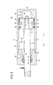
- FIG. 1 is an overall cross-sectional view of a fluid pressure cylinder in which a wear ring according to a first embodiment of the present invention is used.
- FIG. 2 is an enlarged sectional view showing the vicinity of the wear ring in the fluid pressure cylinder of FIG.
- FIG. 3 is a front view of the wear ring shown in FIG. 4 is a cross-sectional view taken along line IV-IV in FIG.
- FIG. 5 is an overall cross-sectional view showing a case where the piston and the piston rod incline with respect to the axis of the cylinder tube in the fluid pressure cylinder of FIG.
- FIG. 6 is an enlarged sectional view showing the vicinity of the wear ring in the fluid pressure cylinder of FIG. FIG.
- FIG. 7 is an enlarged sectional view showing the vicinity of the wear ring according to the second embodiment of the present invention.
- FIG. 8 is an enlarged sectional view showing a modification of the wear ring of FIG.
- FIG. 9 is an enlarged cross-sectional view showing another modification of the wear ring of FIG.
- reference numeral 10 indicates a fluid pressure cylinder which is a linear actuator to which a wear ring according to the first embodiment of the present invention is applied.
- the fluid pressure cylinder 10 includes a cylinder tube (body) 12 formed in a bottomed cylindrical shape, and a rod cover 14 attached to an open end of the cylinder tube 12. And a piston (displacement body) 16 that displaces the inside of the cylinder tube 12 along the axial direction (arrows A and B directions), a piston rod 18 connected to the piston 16, and an outer peripheral surface of the piston 16. And a wear ring 20 to be mounted.
- a first port 22 through which pressure fluid is supplied and discharged is formed on one side of the cylinder tube 12.
- the first port 22 communicates with a cylinder chamber 26 formed inside the cylinder tube 12 through a communication path 24.
- the cylinder chamber 26 is formed along the inside of the cylinder tube 12, and the piston 16 is disposed in the cylinder chamber 26 so as to be freely displaceable.
- the cylinder chamber 26 includes a first cylinder chamber 28 formed between the piston 16 and one end portion where the cylinder tube 12 is closed, and a second cylinder chamber formed between the piston 16 and the rod cover 14. 32. That is, the first cylinder chamber 28 communicates with the first port 22 through the communication path 24.
- the rod cover 14 is integrally connected by being threaded on the outer peripheral surface of one end thereof and screwed to the opening end of the cylinder tube 12. At this time, the seal member 34 attached to the opening end of the cylinder tube 12 abuts against the end surface of the rod cover 14, so that the airtightness in the cylinder chamber 26 is suitably maintained.
- a second port 36 through which pressure fluid is supplied and discharged is formed on the side surface of the rod cover 14, and the second port 36 has a rod hole 40 penetrating through the central portion of the rod cover 14 through the communication path 38. Communicate.
- This rod hole 40 penetrates along the axial direction (arrow A, B direction) of the rod cover 14, and the piston rod 18 is inserted through the rod hole 40 so as to be displaceable.
- a bush 42 is attached to the rod hole 40 through an annular groove at a substantially central portion along the axial direction.
- a rod packing 44 is mounted via an annular groove.
- the bush 42 is formed, for example, from a metal material into a ring shape having a substantially rectangular cross section, and the inner peripheral surface thereof is in contact with the outer peripheral surface of the piston rod 18.
- the piston 16 is made of, for example, a metal material, and is inserted into a piston hole 46 penetrating through the center of the piston 16 on one end side (in the direction of arrow A) of the piston rod 18 and is connected by being screwed.
- first to third annular grooves 48, 50, 52 are formed on the outer peripheral surface of the piston 16 so as to be spaced apart by a predetermined distance along the axial direction (arrow A, B direction) of the piston 16.
- the first annular groove 48 is provided closest to the rod cover 14 (in the direction of arrow B), and a piston packing 54 is mounted inside the first annular groove 48.
- a magnet 56 is installed in the second annular groove 50 adjacent to the first annular groove 48.
- the wear ring 20 is attached to the third annular groove (groove portion) 52 that is farthest from the rod cover 14.
- the first to third annular grooves 48, 50, 52 are all formed in a substantially rectangular cross section.
- the air tightness of the first and second cylinder chambers 28 and 32 in the cylinder tube 12 is suitably maintained by the piston packing 54, and the magnet 56 is connected via position detecting means (not shown) provided in the cylinder tube 12.
- position detecting means not shown
- the position along the axial direction (arrow A, B direction) of the piston 16 can be detected.
- the wear ring 20 is formed of, for example, a resin material and includes an annular main body 58 that contacts the inner wall surface 12a of the cylinder tube 12.
- the main body 58 has a cutout portion 60 that is partially cut along the axial direction (arrow A and B directions), and is formed so as to be radially expandable in the radial direction via the cutout portion 60.
- the cross section is formed in a substantially rectangular shape that is long in the axial direction.
- the outer peripheral surface 58a of the main body portion 58 is formed in a cross-sectional plane substantially parallel to the axis of the main body portion 58, while the inner peripheral surface 58b of the main body portion 58 is gentle with a predetermined radius in the radially inward direction.
- a chamfered portion 64 inclined in an oblique direction is formed at a boundary portion between the inner peripheral surface 58b and both side walls 62a and 62b.
- the chamfered portion 64 is formed at an angle of 45 ° with respect to the side walls 62a and 62b, for example. That is, the wear ring 20 is held in a state in which the inner peripheral surface 58 b formed in an arcuate cross section is in line contact with the bottom wall surface of the third annular groove 52.
- the outer peripheral surface 58 a is in surface contact with and contacts the inner wall surface 12 a of the cylinder tube 12, while the inner peripheral surface 58 b is the third annular shape in the cylinder tube 12. It is in contact with the bottom wall surface of the groove 52.
- the piston rod 18 is formed with a thin shaft portion 66 to which the piston 16 is connected on one end side (arrow A direction), and has a diameter larger than that of the thin shaft portion 66 on the other end side (arrow B direction).
- the thick shaft portion 68 is formed.
- the thick shaft portion 68 is inserted into the rod hole 40 of the rod cover 14 and is supported via the bush 42 so as to be displaceable along the axial direction (arrow A and B directions). Further, the rod packing 44 comes into contact with the outer peripheral surface 58a of the thick shaft portion 68, and leakage of the pressure fluid from between the rod hole 40 and the piston rod 18 is prevented.
- the fluid pressure cylinder 10 that is a linear actuator using the wear ring 20 according to the first embodiment of the present invention is basically configured as described above. The effect will be described.
- a pressure fluid for example, compressed air
- a pressure fluid supply source not shown
- the pressure fluid supplied to the first port 22 is introduced into the first cylinder chamber 28 through the communication path 24. Is done.
- the piston 16 provided in the cylinder tube 12 is pressed from the initial position shown in FIG. 1 toward the rod cover 14 (arrow B direction), and the piston 16 moves toward the rod cover 14. Displace.
- the pressure fluid in the second cylinder chamber 32 is discharged to the outside from the second port 36 in a state where no pressure fluid is supplied through the communication passage 38.
- the wear ring 20 is displaced while its outer peripheral surface 58a is in sliding contact with the inner wall surface 12a of the cylinder chamber 26.
- the pressure fluid supply source (not shown) is supplied to the first port 22.
- the pressurized fluid is supplied to the second port 36 under the switching action of a switching valve (not shown), and the first port 22 is not supplied with the pressurized fluid.
- the pressure fluid supplied to the second port 36 is introduced into the second cylinder chamber 32 through the communication passage 38, and the piston 16 is pressed in a direction away from the rod cover 14 (arrow A direction), whereby the piston 16 is displaced away from the rod cover 14.
- the wear ring 20 is displaced while its outer peripheral surface 58a is in sliding contact with the inner wall surface 12a of the cylinder chamber 26, and the inner peripheral surface 58b is in contact with the bottom wall surface of the third annular groove 52. is there.
- the pressure fluid in the first cylinder chamber 28 is discharged from the first port 22 to the outside through the communication path 24.
- a load F is applied to the other end portion of the piston rod 18 in a direction orthogonal to the axis of the piston rod 18 (vertical direction), and the piston rod 18 and the piston 16 are directed to the axis of the cylinder tube 12.
- tilting will be described with reference to FIGS.
- the inner peripheral surface 58b of the wear ring 20 has a circular arc shape and bulges in the radially inward direction, the inner peripheral surface 58a remains in surface contact with the inner wall surface 12a of the cylinder tube 12.
- the wear ring 20 tilts inside the third annular groove 52 using 58b as a fulcrum. That is, the wear ring 20 is tilted by a predetermined angle with respect to the piston 16 so as to maintain a contact state with the inner wall surface 12a of the cylinder tube 12 when the piston 16 is tilted with respect to the axis of the cylinder tube 12. Therefore, the contact area between the inner peripheral surface 58b and the outer peripheral surface 58a of the wear ring 20 does not change.
- the wear ring 20 is tilted so as to be inclined with respect to the axis line from a state substantially parallel to the axis line of the piston 16, so that the outer peripheral surface 58 a of the wear ring 20 is always moved along the inner wall surface 12 a of the cylinder tube 12. Can be kept in surface contact with each other.
- the contact area between the wear ring 20 and the cylinder tube 12 can be made constant at all times.
- an increase in the surface pressure applied to the wear ring 20 can be suppressed. That is, the contact area of the wear ring 20 with respect to the cylinder tube 12 does not change, and a stable contact area can be obtained.
- FIG. 1 a wear ring 100 according to a second embodiment and a fluid pressure cylinder 102 to which the wear ring 100 is applied are shown in FIG.
- the same referential mark is attached
- the wear ring 100 according to the second embodiment is the first embodiment in that the outer peripheral surface 104a of the main body 104 has a groove portion (lubricating groove) 106 that can be filled with the lubricant S. This is different from the wear ring 20 according to FIG.
- the inner peripheral surface 104b of the wear ring 100 is formed in substantially the same shape as the wear ring 20 according to the first embodiment.
- the groove 106 is formed in a rectangular cross section, is formed in an annular shape along the outer peripheral surface 104a of the main body 104, and has a width dimension along the axial direction (arrow A, B direction) of the main body 104. Is provided at a substantially central portion.
- the cross-sectional shape of the groove 106 is not limited to a rectangular shape.
- a groove (lubricating groove) 106a is connected to the inner peripheral side of the main body 104 like a wear ring 100a shown in FIG. It is good also as a cross-sectional triangle shape which becomes a taper shape toward. Then, when the outer peripheral surface 104a of the main body 104 comes into contact with the inner wall surface 12a of the cylinder tube 12, the lubricant S is sealed in the grooves 106 and 106a.
- the groove 106 is not limited to a single case with respect to the outer peripheral surface 104a of the main body 104.
- the width of the main body 104 can be changed like a wear ring 100b shown in FIG.
- a pair of groove portions (lubricating grooves) 106b may be provided in parallel at positions that are spaced apart from each other by a predetermined distance from the center in the direction and on the side walls 62a and 62b side.
- the cross-sectional area of the pair of groove portions 106b substantially equal to the cross-sectional area of the single groove portion 106, the filling amount of the lubricant S filled in the groove portions 106b can be made equal. Become.
- the wear ring used in the linear actuator according to the present invention is not limited to the above-described embodiment, and it is needless to say that various configurations can be adopted without departing from the gist of the present invention.
Abstract
本発明は、ウェアリングに関するものであり、このウェアリング(20)は、流体圧シリンダ(10)におけるピストン(16)の外周側に装着され、環状に形成された本体部(58)の内周面(58b)が、半径内方向に向かって断面円弧状に膨出して形成される。一方、本体部(58)の外周面(58a)が、該本体部(58)の軸線と略平行な平面状に形成されシリンダチューブ(12)の内壁面(12a)に当接する。そして、ウェアリング(20)は、その内周面(58b)によってピストン(16)の第3環状溝(52)に対して傾動自在に設けられる。
Description
本発明は、軸線方向に沿って変位する変位体を備える直線作動装置に用いられ、前記変位体に装着されるウェアリングに関する。
従来から、例えば、ワークの搬送や位置決め、あるいは種々の産業機械を駆動させるための駆動手段として圧力流体によって直線変位するピストンを備えた流体圧シリンダが知られている。
この流体圧シリンダは、例えば、特開平5-187413号公報に開示されているように、筒状のシリンダチューブの内部にピストンが変位自在に挿通され、前記ピストンに連結されたピストンロッドがロッドカバーによって変位自在に支持されている。そして、シリンダチューブ及びロッドカバーに設けられたポートから前記シリンダチューブ内に圧力流体が導入されることにより、前記ピストン及びピストンロッドが軸線方向に沿って変位する。このような流体圧シリンダでは、ピストンの外周面にパッキン及びウェアリングが装着され、シリンダチューブの内周面に摺接している。
上述したような流体圧シリンダでは、一般的に、ピストンがシリンダチューブに対して同軸上に配置され、その外周面に設けられたパッキン及びウェアリングが、前記シリンダチューブの内周面に対して均一に摺接するように構成されている。しかしながら、例えば、シリンダチューブから突出したピストンロッドの端部に、その軸線と直交方向に荷重が付与された場合、又は、前記ピストンロッド等の自重によって該ピストンロッドと共にピストンが前記シリンダチューブ内で若干だけ傾斜した際、パッキン及びウェアリングが、前記シリンダチューブの内周面に対して片辺りすることとなる。これにより、ピストンが変位する際の摺動抵抗が増加し、該ピストンの変位抵抗となると共に、ウェアリングが偏摩耗してしまうことがある。
本発明の一般的な目的は、変位体がボディに対して傾斜した場合でも、前記変位体を円滑に直線変位させることが可能な直線作動装置に用いられるウェアリングを提供することにある。
本発明は、ボディと、該ボディの内部に沿って変位自在に設けられる変位体とを有する直線作動装置において、前記変位体の外周面に溝部を介して装着され前記ボディの内壁面に当接する環状のウェアリングであって、
前記ウェアリングは、環状に形成され、前記内壁面に対して当接する断面平面状の外周面を有した本体部と、
前記本体部の内周面に設けられ、半径内方向に向かって膨出した断面形状で形成され、前記溝部の底壁に当接する膨出部と、
を備え、
前記本体部は、前記変位体が前記ボディの軸線に対して傾斜した際、前記外周面が前記内壁面に当接した状態を維持しつつ前記溝部内において傾動することを特徴とする。
前記ウェアリングは、環状に形成され、前記内壁面に対して当接する断面平面状の外周面を有した本体部と、
前記本体部の内周面に設けられ、半径内方向に向かって膨出した断面形状で形成され、前記溝部の底壁に当接する膨出部と、
を備え、
前記本体部は、前記変位体が前記ボディの軸線に対して傾斜した際、前記外周面が前記内壁面に当接した状態を維持しつつ前記溝部内において傾動することを特徴とする。
本発明によれば、変位体の外周面に溝部を介して装着されるウェアリングにおいて、ボディの内壁面に対して当接する断面平面状の外周面を有した環状の本体部と、前記本体部の内周面に設けられ、半径内方向に向かって膨出した断面形状の膨出部とを備え、前記膨出部が前記溝部の底壁に当接するように装着される。そして、変位体がボディの軸線に対して傾斜した際に、ウェアリングは、その外周面がボディの内壁面に当接した状態を維持するために溝部内で傾動動作する。
従って、直線作動装置において、何らかの原因で変位体がボディの軸線に対して傾斜した場合でも、ウェアリングが膨出部を介して傾動動作することによって本体部の外周面とボディの内壁面との接触面積が変化してしまうことがなく、常に一定の接触面積とすることができる。
その結果、変位体が傾斜した場合でも、ウェアリングに付与される面圧の増加を抑制することができるため、変位体がボディの内部に沿って変位する際の摺動抵抗が増加してしまうことが回避され、前記ウェアリングによって前記変位体をボディに沿って円滑且つ安定的に変位させることができる。
図1において、参照符号10は、本発明の第1の実施の形態に係るウェアリングの適用された直線作動装置である流体圧シリンダを示す。
この流体圧シリンダ10は、図1及び図2に示されるように、有底筒状に形成されるシリンダチューブ(ボディ)12と、前記シリンダチューブ12の開口した端部に装着されるロッドカバー14と、前記シリンダチューブ12の内部を軸線方向(矢印A、B方向)に沿って変位するピストン(変位体)16と、前記ピストン16に連結されるピストンロッド18と、前記ピストン16の外周面に装着されるウェアリング20とを含む。
シリンダチューブ12の一端部には、その側面に圧力流体が供給・排出される第1ポート22が形成されている。第1ポート22は、連通路24を介して前記シリンダチューブ12の内部に形成されたシリンダ室26と連通する。また、シリンダ室26は、シリンダチューブ12の内部に沿って形成され、該シリンダ室26にピストン16が変位自在に配設される。このシリンダ室26は、ピストン16とシリンダチューブ12の閉塞された一端部との間に形成される第1シリンダ室28と、前記ピストン16とロッドカバー14との間に形成される第2シリンダ室32とから構成される。すなわち、第1シリンダ室28が、連通路24を通じて第1ポート22と連通している。
ロッドカバー14は、その一端部の外周面にねじ部が刻設され、シリンダチューブ12の開口端部に対して螺合されることにより一体的に連結される。この際、シリンダチューブ12の開口端部に装着されたシール部材34が前記ロッドカバー14の端面に当接することにより、シリンダ室26内の気密が好適に保持される。
また、ロッドカバー14の側面には、圧力流体が供給・排出される第2ポート36が形成され、該第2ポート36は連通路38を通じて該ロッドカバー14の中央部を貫通したロッド孔40と連通している。このロッド孔40は、ロッドカバー14の軸線方向(矢印A、B方向)に沿って貫通し、その内部にはピストンロッド18が変位自在に挿通されている。
ロッド孔40には、軸線方向に沿った略中央部に環状溝を介してブッシュ42が装着されると共に、前記ブッシュ42と隣接したロッドカバー14の他端部側(矢印B方向)には、環状溝を介してロッドパッキン44が装着されている。ブッシュ42は、例えば、金属製材料から断面略長方形状のリング状に形成され、その内周面がピストンロッド18の外周面に当接している。そして、ピストンロッド18が軸線方向(矢印A、B方向)に沿って変位する際、その外周面に当接することによって変位自在に支持している。
ピストン16は、例えば、金属製材料から形成され、その中心部を貫通したピストン孔46にピストンロッド18の一端部側(矢印A方向)に挿通され、螺合されることによって連結される。
また、ピストン16の外周面には、該ピストン16の軸線方向(矢印A、B方向)に沿って所定間隔離間した第1~第3環状溝48、50、52が形成される。第1環状溝48は、最もロッドカバー14側(矢印B方向)に設けられ、その内部にはピストンパッキン54が装着され、該第1環状溝48に隣接した第2環状溝50にはマグネット56が装着され、最も前記ロッドカバー14から離間した第3環状溝(溝部)52にはウェアリング20が装着される。なお、第1~第3環状溝48、50、52は、いずれも断面略矩形状に形成される。
すなわち、ピストンパッキン54によってシリンダチューブ12における第1及び第2シリンダ室28、32の気密が好適に保持されると共に、シリンダチューブ12に設けられた位置検出手段(図示しない)を介してマグネット56を検出することにより、前記ピストン16の軸線方向(矢印A、B方向)に沿った位置を検出することが可能となる。
ウェアリング20は、図1~図4に示されるように、例えば、樹脂製材料から形成され、シリンダチューブ12の内壁面12aに当接する環状の本体部58を備える。
本体部58は、その一部が軸線方向(矢印A、B方向)に沿って切断された切欠部60を有し、該切欠部60を介して半径方向に拡径自在に形成されると共に、前記軸線方向に長尺な断面略長方形状に形成される。
この本体部58の外周面58aは、該本体部58の軸線と略平行な断面平面状に形成され、一方、前記本体部58の内周面58bは、半径内方向に向かって所定半径で緩やかに膨出した断面円弧状に形成され、該内周面58bと両側壁62a、62bとの境界部位には、斜め方向に傾斜した面取部64がそれぞれ形成される。面取部64は、例えば、側壁62a、62bに対して45°の角度で形成される。すなわち、ウェアリング20は、断面円弧状に形成された内周面58bが第3環状溝52の底壁面に対して線接触した状態で保持されている。
そして、ウェアリング20がピストン16に装着された状態において、その外周面58aがシリンダチューブ12の内壁面12aに面接触して当接し、一方、内周面58bが前記シリンダチューブ12における第3環状溝52の底壁面に当接している。
ピストンロッド18は、その一端部側(矢印A方向)にピストン16の連結される細軸部66が形成されると共に、他端部側(矢印B方向)には前記細軸部66より拡径した太軸部68が形成される。そして、太軸部68は、ロッドカバー14のロッド孔40に挿通され、ブッシュ42を介して軸線方向(矢印A、B方向)に沿って変位自在に支持される。また、太軸部68の外周面58aにロッドパッキン44が当接し、ロッド孔40とピストンロッド18との間からの圧力流体の漏出が防止される。
本発明の第1の実施の形態に係るウェアリング20の用いられた直線作動装置である流体圧シリンダ10は、基本的には以上のように構成されるものであり、次にその動作並びに作用効果について説明する。
図示しない圧力流体供給源から第1ポート22に圧力流体(例えば、圧縮エア)を供給することにより、前記第1ポート22に供給された圧力流体が、連通路24を通じて第1シリンダ室28に導入される。これにより、シリンダチューブ12の内部に設けられたピストン16が、図1に示される初期位置からロッドカバー14側(矢印B方向)に向かって押圧され、前記ピストン16がロッドカバー14側に向かって変位する。なお、第2シリンダ室32における圧力流体は、連通路38を通じて圧力流体の供給されていない状態にある第2ポート36から外部へと排出される。
この際、ウェアリング20は、その外周面58aがシリンダ室26の内壁面12aに摺接しながら変位する。
そして、ピストン16が、ロッドカバー14の端面に当接することにより流体圧シリンダ10におけるピストン16の変位終端位置となる。
一方、上述した変位終端位置にあるピストン16をロッドカバー14から離間させる方向(矢印A方向)へと変位させる場合には、第1ポート22に圧力流体供給源(図示せず)から供給されていた圧力流体を、図示しない切換弁の切換作用下に第2ポート36へと供給すると共に、前記第1ポート22を圧力流体が供給されていない状態とする。
第2ポート36に供給された圧力流体は、連通路38を通じて第2シリンダ室32に導入され、ピストン16がロッドカバー14から離間する方向(矢印A方向)へと押圧されることにより、前記ピストン16が前記ロッドカバー14から離間する方向へと変位する。この場合も同様に、ウェアリング20は、その外周面58aがシリンダ室26の内壁面12aに摺接しながら変位し、内周面58bは、第3環状溝52の底壁面に当接した状態にある。なお、第1シリンダ室28における圧力流体は、連通路24を通じて第1ポート22から外部へと排出される。
そして、ピストン16が、シリンダチューブ12の閉塞された一端部側(矢印A方向)に当接することにより、流体圧シリンダ10におけるピストン16の初期位置へと復帰する(図1参照)。
次に、例えば、ピストンロッド18の他端部に対して該ピストンロッド18の軸線と直交方向(鉛直方向)に荷重Fが付与され前記ピストンロッド18及びピストン16がシリンダチューブ12の軸線に対して傾斜した場合について、図5及び図6を参照しながら説明する。
このような荷重F(図5参照)が付与された場合には、ピストンロッド18の他端部が下方へと押圧され、ロッドカバー14によって支持された部位を支点として前記他端部が下方へと所定角度だけ傾斜した状態となる。これにより、ピストンロッド18の一端部及び該一端部に連結されたピストン16が、ピストン16の外周面58aとシリンダ室26の内壁面12aとの間に設けられたクリアランスを介してシリンダ室26内で上方に向かって所定角度だけ傾斜した状態となる。
この際、ウェアリング20は、その内周面58bが断面円弧状で半径内方向に膨出しているため、外周面58aがシリンダチューブ12の内壁面12aに面接触した状態のまま前記内周面58bを支点として前記ウェアリング20が第3環状溝52の内部で傾動する。すなわち、ウェアリング20は、ピストン16がシリンダチューブ12の軸線に対して傾斜した際、前記シリンダチューブ12の内壁面12aとの当接状態を維持するように前記ピストン16に対して所定角度だけ傾動するため、前記内周面58bと前記ウェアリング20の外周面58aとの接触面積が変わることがない。
換言すれば、ウェアリング20は、ピストン16の軸線と略平行な状態から該軸線に対して傾斜するように傾動することにより、前記ウェアリング20の外周面58aを常にシリンダチューブ12の内壁面12aに対して面接触させておくことが可能となる。
その結果、何らかの原因でピストンロッド18の他端部に対して荷重Fが付与され、前記ピストン16がシリンダ室26内において傾斜した場合でも、ピストンロッド18及びピストン16が、シリンダチューブ12の軸線と同軸上に設けられた通常状態(図1参照)と比較し、ウェアリング20とシリンダチューブ12との接触面積を常に一定とすることができ、それに伴って、前記シリンダチューブ12に当接した際に前記ウェアリング20に付与される面圧の増加を抑制することができる。すなわち、シリンダチューブ12に対するウェアリング20の接触面積が変化することがなく、安定した接触面積が得られる。
これにより、流体圧シリンダ10において、ピストン16を軸線方向(矢印A、B方向)に沿って変位する際の摺動抵抗が増加してしまうことが回避され、前記ウェアリング20によってピストン16及びピストンロッド18をシリンダチューブ12の軸線方向(矢印A、B方向)に沿って円滑且つ安定的に変位させることが可能となる。
次に、第2の実施の形態に係るウェアリング100及び該ウェアリング100の適用された流体圧シリンダ102を図7に示す。なお、上述した第1の実施の形態に係る該ウェアリング20の適用された流体圧シリンダ10と同一の構成要素には同一の参照符号を付して、その詳細な説明を省略する。
この第2の実施の形態に係るウェアリング100では、本体部104の外周面104aに潤滑剤Sの充填可能な溝部(潤滑用溝)106を有している点で、第1の実施の形態に係るウェアリング20と相違している。なお、ウェアリング100の内周面104bは、第1の実施の形態に係るウェアリング20と略同一の形状で形成される。
この溝部106は、例えば、断面矩形状に形成され、本体部104の外周面104aに沿って環状に形成されると共に、前記本体部104の軸線方向(矢印A、B方向)に沿った幅寸法の略中央部に設けられる。
なお、この溝部106の断面形状は、矩形状に限定されるものではなく、例えば、図8に示されるウェアリング100aのように、溝部(潤滑用溝)106aを、本体部104の内周側に向かって先細状となる断面三角形状としてもよい。 そして、本体部104の外周面104aがシリンダチューブ12の内壁面12aに当接した際、溝部106、106aの内部に潤滑剤Sが封入された状態となる。
さらに、溝部106は、本体部104の外周面104aに対して単一で設けられる場合に限定されるものではなく、例えば、図9に示されるウェアリング100bのように、該本体部104の幅方向中央から互いに所定間隔離間し、両側壁62a、62b側となる位置に一組の溝部(潤滑用溝)106bを並列に設けるようにしてもよい。この場合、一組の溝部106bの断面積を、単一の溝部106の断面積と略同等とすることにより、該溝部106bに充填される潤滑剤Sの充填量を同等とすることが可能となる。
これらのウェアリング100、100a、100bがピストン16に装着された状態において、その外周面104aがシリンダチューブ12の内壁面12aに面接触して当接し、溝部106、106a、106bに充填された潤滑剤Sによって前記ピストン16とシリンダチューブ12との間の潤滑がなされるため、前記ピストン16が前記シリンダチューブ12に沿ってより一層円滑に変位させることが可能となる。
なお、本発明に係る直線作動装置に用いられるウェアリングは、上述の実施の形態に限らず、本発明の要旨を逸脱することなく、種々の構成を採り得ることはもちろんである。
Claims (9)
- ボディ(12)と、該ボディ(12)の内部に沿って変位自在に設けられる変位体(16)を有する直線作動装置(10、102)において、前記変位体(16)の外周面に溝部(52)を介して装着され前記ボディ(12)の内壁面に当接する環状のウェアリング(20、100、100a、100b)であって、
前記ウェアリング(20、100、100a、100b)は、環状に形成され、前記内壁面に対して当接する断面平面状の外周面(58a)を有した本体部(58、104)と、
前記本体部(58、104)の内周面(58b)に設けられ、半径内方向に向かって膨出した断面形状で形成され、前記溝部(52)の底壁に当接する膨出部と、
を備え、
前記本体部(58、104)は、前記変位体(16)が前記ボディ(12)の軸線に対して傾斜した際、前記外周面(58a)が前記内壁面に当接した状態を維持しつつ前記溝部(52)内において傾動することを特徴とする直線作動装置に用いられるウェアリング。 - 請求項1記載のウェアリングにおいて、
前記膨出部は、断面円弧状に膨出して形成されることを特徴とする直線作動装置に用いられるウェアリング。 - 請求項2記載のウェアリングにおいて、
前記膨出部は、前記溝部(52)に対して線接触するように設けられることを特徴とする直線作動装置に用いられるウェアリング。 - 請求項1記載のウェアリングにおいて、
前記本体部(104)には、潤滑剤が充填され、前記ボディ(12)と前記変位体(16)との間に前記潤滑剤を供給する潤滑用溝(106、106a、106b)が設けられることを特徴とする直線作動装置に用いられるウェアリング。 - 請求項4記載のウェアリングにおいて、
前記潤滑用溝(106、106a、106b)は、前記本体部(104)の外周面(104a)に形成されることを特徴とする直線作動装置に用いられるウェアリング。 - 請求項4記載のウェアリングにおいて、
前記潤滑用溝(106b)は、複数設けられ互いに離間して並列に配置されることを特徴とする直線作動装置に用いられるウェアリング。 - 請求項5記載のウェアリングにおいて、
前記潤滑用溝(106b)は、複数設けられ互いに離間して並列に配置されることを特徴とする直線作動装置に用いられるウェアリング。 - 請求項1記載のウェアリングにおいて、
前記本体部(58、104)の内周面(58b、104b)には、前記膨出部と近接した一組の面取部(64)が形成されることを特徴とする直線作動装置に用いられるウェアリング。 - 請求項4記載のウェアリングにおいて、
前記潤滑用溝(106、106a、106b)は、断面矩形状、又は、前記本体部(104)の内周側に向かって先細状となる断面三角形状に形成されることを特徴とする直線作動装置に用いられるウェアリング。
Applications Claiming Priority (2)
| Application Number | Priority Date | Filing Date | Title |
|---|---|---|---|
| JP2011098866A JP5397407B2 (ja) | 2011-04-27 | 2011-04-27 | 直線作動装置に用いられるウェアリング |
| JP2011-098866 | 2011-04-27 |
Publications (1)
| Publication Number | Publication Date |
|---|---|
| WO2012147599A1 true WO2012147599A1 (ja) | 2012-11-01 |
Family
ID=47072120
Family Applications (1)
| Application Number | Title | Priority Date | Filing Date |
|---|---|---|---|
| PCT/JP2012/060537 WO2012147599A1 (ja) | 2011-04-27 | 2012-04-19 | 直線作動装置に用いられるウェアリング |
Country Status (3)
| Country | Link |
|---|---|
| JP (1) | JP5397407B2 (ja) |
| TW (1) | TWI547658B (ja) |
| WO (1) | WO2012147599A1 (ja) |
Families Citing this family (3)
| Publication number | Priority date | Publication date | Assignee | Title |
|---|---|---|---|---|
| JP6103349B2 (ja) | 2012-12-10 | 2017-03-29 | Smc株式会社 | 流体圧シリンダ |
| JP6240983B2 (ja) | 2014-04-01 | 2017-12-06 | Smc株式会社 | 流体圧シリンダ |
| JP6808182B2 (ja) | 2017-09-07 | 2021-01-06 | Smc株式会社 | 流体圧シリンダ |
Citations (5)
| Publication number | Priority date | Publication date | Assignee | Title |
|---|---|---|---|---|
| JPS62856U (ja) * | 1985-06-19 | 1987-01-07 | ||
| JPS628401U (ja) * | 1986-02-26 | 1987-01-19 | ||
| JPS6228086A (ja) * | 1985-07-26 | 1987-02-06 | Tanaka Kikinzoku Kogyo Kk | 抵抗溶接装置 |
| JPH02114780U (ja) * | 1989-03-01 | 1990-09-13 | ||
| JPH062768A (ja) * | 1992-06-18 | 1994-01-11 | Tokico Ltd | 揺動式圧縮機のピストンリング |
Family Cites Families (3)
| Publication number | Priority date | Publication date | Assignee | Title |
|---|---|---|---|---|
| US3333513A (en) * | 1963-01-15 | 1967-08-01 | Wettstein Fritz Alexander | Guide arrangement for pistons and cylinders |
| JPS6228086U (ja) * | 1985-08-05 | 1987-02-20 | ||
| JP4737454B2 (ja) * | 2006-12-06 | 2011-08-03 | Smc株式会社 | 流体圧シリンダに用いられる止め輪 |
-
2011
- 2011-04-27 JP JP2011098866A patent/JP5397407B2/ja not_active Expired - Fee Related
-
2012
- 2012-04-19 WO PCT/JP2012/060537 patent/WO2012147599A1/ja active Application Filing
- 2012-04-25 TW TW101114653A patent/TWI547658B/zh not_active IP Right Cessation
Patent Citations (5)
| Publication number | Priority date | Publication date | Assignee | Title |
|---|---|---|---|---|
| JPS62856U (ja) * | 1985-06-19 | 1987-01-07 | ||
| JPS6228086A (ja) * | 1985-07-26 | 1987-02-06 | Tanaka Kikinzoku Kogyo Kk | 抵抗溶接装置 |
| JPS628401U (ja) * | 1986-02-26 | 1987-01-19 | ||
| JPH02114780U (ja) * | 1989-03-01 | 1990-09-13 | ||
| JPH062768A (ja) * | 1992-06-18 | 1994-01-11 | Tokico Ltd | 揺動式圧縮機のピストンリング |
Also Published As
| Publication number | Publication date |
|---|---|
| JP2012229760A (ja) | 2012-11-22 |
| TWI547658B (zh) | 2016-09-01 |
| TW201307710A (zh) | 2013-02-16 |
| JP5397407B2 (ja) | 2014-01-22 |
Similar Documents
| Publication | Publication Date | Title |
|---|---|---|
| KR101945788B1 (ko) | 유체압 실린더 | |
| JP3191509U (ja) | 流体圧シリンダ | |
| US8739684B2 (en) | Fluid pressure apparatus | |
| KR20080048970A (ko) | 유체압 실린더 | |
| JP6159938B2 (ja) | 流体圧シリンダ | |
| US20110283883A1 (en) | Fluid pressure apparatus | |
| US10316868B2 (en) | Fluid pressure cylinder | |
| WO2012147599A1 (ja) | 直線作動装置に用いられるウェアリング | |
| JP2017015245A (ja) | 流体圧シリンダ | |
| US10480540B2 (en) | Double-acting cylinder | |
| US10451093B2 (en) | Fluid pressure cylinder | |
| JP5665030B2 (ja) | 直線作動装置に用いられるウェアリング | |
| EP3673179B1 (en) | Actuator bearing arrangement | |
| KR20210031906A (ko) | 스풀식 스위칭 밸브에 있어서의 시일 구조 및 그 스풀식 스위칭 밸브 | |
| KR102066407B1 (ko) | 차량 브레이크 시스템의 펌프 부재용 밀봉 링 | |
| JP6796291B2 (ja) | エアシリンダ | |
| KR200457197Y1 (ko) | 스풀밸브용 패킹 및 이를 장착한 스풀밸브 |
Legal Events
| Date | Code | Title | Description |
|---|---|---|---|
| 121 | Ep: the epo has been informed by wipo that ep was designated in this application |
Ref document number: 12777666 Country of ref document: EP Kind code of ref document: A1 |
|
| NENP | Non-entry into the national phase |
Ref country code: DE |
|
| 122 | Ep: pct application non-entry in european phase |
Ref document number: 12777666 Country of ref document: EP Kind code of ref document: A1 |