WO2012147416A1 - 半導体製造装置用溶接ベローズ - Google Patents
半導体製造装置用溶接ベローズ Download PDFInfo
- Publication number
- WO2012147416A1 WO2012147416A1 PCT/JP2012/056061 JP2012056061W WO2012147416A1 WO 2012147416 A1 WO2012147416 A1 WO 2012147416A1 JP 2012056061 W JP2012056061 W JP 2012056061W WO 2012147416 A1 WO2012147416 A1 WO 2012147416A1
- Authority
- WO
- WIPO (PCT)
- Prior art keywords
- bellows
- plate
- processing
- welding
- semiconductor manufacturing
- Prior art date
- Legal status (The legal status is an assumption and is not a legal conclusion. Google has not performed a legal analysis and makes no representation as to the accuracy of the status listed.)
- Ceased
Links
Images



Classifications
-
- F—MECHANICAL ENGINEERING; LIGHTING; HEATING; WEAPONS; BLASTING
- F16—ENGINEERING ELEMENTS AND UNITS; GENERAL MEASURES FOR PRODUCING AND MAINTAINING EFFECTIVE FUNCTIONING OF MACHINES OR INSTALLATIONS; THERMAL INSULATION IN GENERAL
- F16J—PISTONS; CYLINDERS; SEALINGS
- F16J3/00—Diaphragms; Bellows; Bellows pistons
- F16J3/04—Bellows
- F16J3/047—Metallic bellows
-
- F—MECHANICAL ENGINEERING; LIGHTING; HEATING; WEAPONS; BLASTING
- F16—ENGINEERING ELEMENTS AND UNITS; GENERAL MEASURES FOR PRODUCING AND MAINTAINING EFFECTIVE FUNCTIONING OF MACHINES OR INSTALLATIONS; THERMAL INSULATION IN GENERAL
- F16J—PISTONS; CYLINDERS; SEALINGS
- F16J15/00—Sealings
- F16J15/50—Sealings between relatively-movable members, by means of a sealing without relatively-moving surfaces, e.g. fluid-tight sealings for transmitting motion through a wall
- F16J15/52—Sealings between relatively-movable members, by means of a sealing without relatively-moving surfaces, e.g. fluid-tight sealings for transmitting motion through a wall by means of sealing bellows or diaphragms
-
- F—MECHANICAL ENGINEERING; LIGHTING; HEATING; WEAPONS; BLASTING
- F16—ENGINEERING ELEMENTS AND UNITS; GENERAL MEASURES FOR PRODUCING AND MAINTAINING EFFECTIVE FUNCTIONING OF MACHINES OR INSTALLATIONS; THERMAL INSULATION IN GENERAL
- F16J—PISTONS; CYLINDERS; SEALINGS
- F16J3/00—Diaphragms; Bellows; Bellows pistons
- F16J3/04—Bellows
Definitions
- the present invention relates to a bellows-shaped welding bellows that is used in a sealing part of a semiconductor manufacturing apparatus and has sealing properties and flexibility, and is suitable for sealing a gate valve that can open and close an opening of a vacuum processing chamber, for example. It relates to welding bellows.
- the bellows-shaped weld metal bellows having sealing properties and flexibility are used for sealing moving members of various devices because they can be compressed until the bellows plates are in close contact with each other.
- a weld metal bellows used for sealing a gate valve that can open and close an opening of a vacuum processing chamber used in a manufacturing process of a semiconductor manufacturing apparatus is hermetically sealed between a vacuum side and an atmosphere side.
- a bellows plate 50 is connected to the inner diameter side and the outer diameter side by welding to form a bellows shape, and repeatedly performs expansion and contraction operations of several million strokes at a high speed. (Hereinafter referred to as “prior art 1”). At this time, as shown in FIG.
- a weld metal bellows 60 as shown in FIG. 5 is known as one having excellent corrosion resistance and operating spring properties (hereinafter referred to as “conventional”). This is referred to as “Technology 2”.
- an austenitic stainless steel plate 62 is disposed on the sealed fluid side, and a spring steel plate 63 is disposed on the non-sealed fluid side. And is formed in a double layer by welding.
- a welded metal bellows 70 as shown in FIG. 6 is known as one that provides a bellows that can withstand a large pressure without sacrificing the flexibility of the bellows (hereinafter referred to as “Prior Art 3”).
- Prior Art 3 a welded metal bellows 70 as shown in FIG. 6
- the bellows plate 71 constituting the bellows structure of the welded metal bellows 70 of prior art 3 is formed in a double layer by welding and fixing two discs 72, 73 of uniform thickness on the outer diameter side and inner diameter side. It has been made.
- a vent hole 74 is provided in the atmospheric disk 72 so that no gas pocket exists between the disks 72 and 73.
- the prior art 2 shown in FIG. 5 is intended to provide a welded bellows with excellent corrosion resistance and operating spring properties, and since no countermeasure is taken against repeated bending deformation due to the intrusion of foreign matter, for example, a sealed fluid
- the prior art 3 shown in FIG. 6 provides a bellows that can withstand a large pressure without sacrificing flexibility, and has a vent hole 74 formed in the bellows plate 72 on the atmosphere side.
- the present invention has been made to solve the above-described problems of the prior art, and in a welding bellows for a semiconductor manufacturing apparatus in which the bellows plate has a double structure, of the two bellows plates, the processing side (vacuum) ) And the non-processed (atmosphere) bellows plate, which functions as a sealing and strength member, is less likely to be damaged by foreign matter. It is an object of the present invention to provide a welding bellows having redundancy so that even if the plate is damaged, this can be supplemented by a bellows plate on the non-processing side.
- a welding bellows for a semiconductor manufacturing apparatus is, firstly, a bellows in which a plurality of annular bellows plates that are curved in the radial direction are alternately connected on the outer diameter side and the inner diameter side.
- an annular bellows plate includes a processing side bellows plate and a non-processing side bellows plate, an air layer interposed between the two bellows plates, and a processing side bellows plate
- the plate thickness of the non-process side bellows plate is configured to be thick.
- the welding bellows for a semiconductor manufacturing apparatus is characterized in that, in the first feature, the processing side is vacuum and the non-processing side is air.
- a gate valve capable of airtightly opening and closing an opening of a vacuum processing chamber used in the manufacturing process of the semiconductor manufacturing apparatus. It is used for sealing.
- the welding bellows for a semiconductor manufacturing apparatus is expanded and contracted in a range of several Hz, the expansion speed is 100 mm / sec or more, and the repeated life is. It is characterized by being 1 ⁇ 10 6 or more.
- the processing side bellows plate is less likely to be damaged by foreign matter, and in the unlikely event that the processing side bellows plate is damaged, it can be supplemented by the non-processing side bellows plate. It is possible to provide a welded bellows having the characteristics.
- the processing side bellows plate is used as a discarded plate, so that it has the role of preventing the non-processing side bellows plate from being damaged, and the non-processing side bellows plate has the sealing and strength as the original bellows plate. By providing a role as a member, a welded bellows that can withstand long-term use can be provided.
- the bellows plate on the processing side is thin and has an air layer such as air or Ar gas behind, it can flexibly follow foreign substances. It is hard to break, and furthermore, the bending deformation of the processing side bellows plate due to the intrusion of foreign matter is hardly transmitted to the non-processing side bellows plate due to the presence of the air layer, so that the non-processing side bellows plate can be prevented from being damaged. .
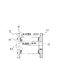
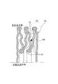
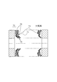
- the main part at the time of using the welding bellows for semiconductor manufacturing apparatuses which concern on embodiment of this invention for the sealing of the support rod of the gate valve which can open and close airtightly the opening part of the vacuum processing chamber used for the manufacturing process of a semiconductor manufacturing apparatus It is sectional drawing. It is sectional drawing which shows the whole structure of the welding bellows for semiconductor manufacturing apparatuses which concerns on embodiment of this invention. It is a schematic diagram which shows the principal part of the welding bellows for semiconductor manufacturing apparatuses which concerns on embodiment of this invention. It is a schematic diagram of the principal part for demonstrating the prior art 1. FIG. It is principal part sectional drawing for demonstrating the prior art 2. FIG. It is principal part sectional drawing for demonstrating the prior art 3. FIG.
- FIG. 1 shows a welding bellows for a semiconductor manufacturing apparatus according to an embodiment of the present invention, which is used for sealing a support rod of a gate valve capable of opening and closing an opening of a vacuum processing chamber used in a manufacturing process of a semiconductor manufacturing apparatus.
- a gate valve 1 has a valve box 3 in which a through hole 2 is formed at a position facing each other, and a pair of valve plates 4 and 5, and a valve assembly disposed in the valve box 3.
- a support rod 7 that supports the valve assembly 6 at the tip, a bellows 8 that seals the valve box 3 side and the support rod 7 side, and the valve assembly 6 is opened via the support rod 7.
- An air cylinder 9 that moves between a position and a valve closing position is provided.
- the gate valve 1 is provided, for example, between vacuum processing chambers S1 and S2 in a semiconductor manufacturing process, and the valve assembly 6 is moved between a valve opening position and a valve closing position by a support rod 7, and the valve is closed.
- a support rod 7 By supplying or discharging compressed air from an air supply device and a vacuum pump (not shown) to the valve assembly 6 positioned at a position, the pair of valve plates 4 and 5 are pressed or separated against the periphery of the through hole 2.
- the gates G of the vacuum processing chambers S1 and S2 can be opened and closed.
- the bellows 8 of the gate valve 1 is a metal member for sealing the valve box 3 side and the support rod 7 side, and one end of the bellows 8 is attached to the bottom plate of the valve box 3 on the O-ring 10.
- the upper ring member 11 is fixed to the upper ring member 11 with a fixed member, for example, by welding or the like, while being kept airtight.
- the other end of the bellows 8 is also fixed to the lower ring member 12 fitted and fixed to the support rod 7 by using, for example, a fixing member or by welding or the like.
- an O-ring 13 is interposed between the lower ring member 12 and the support rod 8, so that even if the support rod 7 moves up and down, the valve box 3 can be sealed, particles and the like from the outside. It is possible to prevent the entry of contaminants.
- the bellows 8 of the gate valve 1 is required to withstand expansion / contraction operation that is expanded / contracted in the range of several Hz, the expansion / contraction speed is 100 mm / sec or more, and the repetition life is about 1 ⁇ 10 6 times. It is difficult to avoid damage with the welded bellows configured as in the prior art.
- FIG. 2 is a cross-sectional view showing an overall configuration of a welding bellows for a semiconductor manufacturing apparatus according to an embodiment of the present invention.
- the bellows 8 is formed in a bellows structure by alternately connecting a plurality of annular bellows plates 15 having a curved surface with respect to the radial direction on the outer diameter side and the inner diameter side.
- the bellows plates 15 are connected to each other by TIG welding or the like in the air or in an Ar gas atmosphere.
- the inner diameter side of the bellows 8 is the processing side, and the degree of vacuum is, for example, 1 ⁇ 10 ⁇ 6 Pa.
- the outer diameter side of the bellows 8 is a non-processing side and is atmospheric pressure.
- the bellows 8 is set to operate in a range of about 0.5 L to 1.2 L with respect to the free length L, for example. Further, the speed of expansion and contraction during operation reaches 100 mm / s or more.
- the bellows 8 is formed of a metal material.
- the upper ring member 11 and the lower ring member 12 are formed of austenitic stainless steel
- the bellows plate 15 is formed of precipitation hardening semi-austenitic stainless steel.
- FIG. 3 is a schematic diagram showing the main part of the welding bellows for a semiconductor manufacturing apparatus according to the first embodiment of the present invention, in which the upper side is the processing side (vacuum) and the lower side is the non-processing side (atmosphere).
- a bellows 8 is formed in a bellows structure in which a plurality of annular bellows plates 15 having a curved surface with respect to the radial direction are alternately connected on the inner diameter side 16 and the outer diameter side 17 by welding.
- the bellows plate 15 is composed of a double layer of a processing side bellows plate 18 and a non-processing side bellows plate 19, and air or a bellows plate 19 is disposed between the processing side bellows plate 18 and the non-processing side bellows plate 19.
- a gas layer 20 such as Ar gas is interposed.
- the processing-side bellows plate 18 is thin, and the non-processing-side bellows plate 19 is thick.
- the processing-side bellows plate 18 and the non-processing-side bellows plate 19 have thicknesses that are set in consideration of operating conditions. However, the processing-side bellows plate 18 is adjacent to a foreign substance 21 in addition to a sealing function.
- the processing-side bellows plate 18 and the non-processing-side bellows plate 19 As materials for the processing-side bellows plate 18 and the non-processing-side bellows plate 19, precipitation-hardening semi-austenitic stainless steel is usually used, but it is not always necessary to use the same material.
- the treatment-side bellows plate 18 may be made of mild steel or spring steel, and the non-treatment-side bellows plate 19 may be made of precipitation hardenable semi-austenitic stainless steel.
- the exposed surface of the processing side bellows plate 18 may be coated with a fluororesin or a silicone resin so that the foreign matter 21 does not directly contact the metal surface.
- an air layer 20 such as air or Ar gas is formed between the processing side bellows plate 18 and the non-processing side bellows plate 19.
- the air layer 20 is welded with an appropriate gap between the bellows plates 18 and 19 when the inner diameter side 16 and the outer diameter side 17 of the bellows plates 18 and 19 are welded in the
- the adjacent bellows plates 15 and 15 repeat contact and separation.
- the bellows plates 18 and 18 on the processing side repeatedly receive the bending force with the foreign matter 21 as a fulcrum. become.
- the bellows plate 18 on the processing side can follow the foreign substance 21 flexibly because the plate thickness is thin and the air layer 20 such as air or Ar gas exists behind. Further, the transmission of the bending force due to the intrusion of the foreign matter 21 to the non-process side bellows plate 19 is considerably reduced by the interposition of the air layer 20.
- the non-processed bellows plate 19 serves as a sealing and strength member as an original bellows plate
- the process-side bellows plate 18 is a non-processed bellows plate 19. Since it plays a role of preventing damage and sealing member, it is redundant with double safety measures.
- the bellows plate 18 on the processing side has a thin plate thickness and an air layer 20 such as air or Ar gas is present behind, so that it can flexibly follow the foreign matter 21.
- the processing-side bellows plate 18 is used as a discard plate, and serves to prevent the non-processing-side bellows plate 19 from being damaged.
Landscapes
- Engineering & Computer Science (AREA)
- General Engineering & Computer Science (AREA)
- Mechanical Engineering (AREA)
- Diaphragms And Bellows (AREA)
- Details Of Valves (AREA)
- Sealing Devices (AREA)
- Sliding Valves (AREA)
Abstract
Description
また、図6に示す従来技術3は可撓性を犠牲にすることなく大きい圧力に耐え得るふいごを提供するものであって、大気側のベローズプレート72に通気孔74が形成されているため、異物75の侵入により大気側と反対側のベローズプレート73が繰返しの曲げ変形により破損されると、もはや密封作用を保持することができなくなり、結局、1枚のベローズプレートの場合と同じ寿命しか有さないという問題があった。
(1)処理側のベローズプレートにより異物による損傷を受けにくくするとともに、万一、処理側のベローズプレートが損傷を受けた場合でもこれを非処理側のベローズプレートで補完することができるため、冗長性のある溶接ベローズを提供することができる。
(2)処理側のベローズプレートを、いわば、捨て板材として使用し、非処理側のベローズプレートの破損を防止する役割を持たせ、非処理側のベローズプレートに本来のベローズプレートとしての密封兼強度部材としての役割を持たせることにより、長期の使用に耐える溶接ベローズを提供することができる。
(3)処理側のベローズプレートは、板厚が薄いこと、及び、空気あるいはArガスなどの気層が背後に存在することから、異物に対してしなやかに追従することができるので、自分自身が破損しにくく、さらに、気層の介在により、異物の侵入に起因する処理側のベローズプレートの曲げ変形が非処理側のベローズプレートにほとんど伝達されないため、非処理側のベローズプレートの破損も防止できる。
図1において、ゲートバルブ1は、相互に対向する位置に通孔2が形成された弁箱3と、一対の弁板4、5を有し、この弁箱3内に配置された弁組立体6と、この弁組立体6を先端に支持している支持ロッド7と、弁箱3側と支持ロッド7側とをシールするベローズ8と、支持ロッド7を介して弁組立体6を開弁位置と閉弁位置との間を移動させるエアシリンダ9、を備えている。
図2において、ベローズ8は、径方向に対して曲面をなす複数の環状のベローズプレート15が外径側及び内径側において交互に接続されて蛇腹構造に形成される。
ベローズプレート15同士の接続は、大気中あるいはArガス雰囲気中でTIG溶接などにより行われる。
図においては、ベローズ8の内径側が処理側で、例えば、1×10⁻⁶Paの真空度となる。ベローズ8の外径側は非処理側であり、大気圧である。
ベローズ8は、例えば、自由長Lに対して、約0.5L~1.2Lの範囲で作動するように設定される。また、作動時における伸縮の速度は、100mm/s以上に達する。
ベローズ8は金属材料から形成されるもので、例えば、上部リング部材11及び下部リング部材12はオーステナイト系ステンレス鋼により形成され、また、ベローズプレート15は、析出硬化性セミオーステナイト系ステンレス鋼により形成される。
図3において、ベローズ8は、径方向に対して曲面をなす複数の環状のベローズプレート15が内径側16及び外径側17において交互に溶接により接続されて蛇腹構造に形成されるものであって、該ベローズプレート15は、処理側のベローズプレート18と非処理側のベローズプレート19との2重の層からなり、処理側のベローズプレート18と非処理側のベローズプレート19との間に空気あるいはArガスなどの気層20が介在されている。また、処理側のベローズプレート18の板厚が薄く、非処理側のベローズプレート19の板厚が厚く構成されている。処理側のベローズプレート18及び非処理側のベローズプレート19の板厚は、作動条件を考慮して設定されるものあるが、処理側のベローズプレート18は、密封機能の他、異物21が隣接するベローズプレート15、15間に侵入した際、この異物に接してしなやかに追従するような機能が要求される。一方、非処理側のベローズプレート19は、密封機能及び強度部材しての機能が要求され、また、万一、処理側のベローズプレート18が破損した場合でも、密封機能を保持するものである。
処理側のベローズプレート18の板圧をt1、非処理側のベローズプレート19の板圧をt2とすると、t1/t2=0.1~0.7の範囲に設定することが望ましい。
また、処理側のベローズプレート18と非処理側のベローズプレート19との間に空気あるいはArガスなどの気層20を形成する。該気層20は、大気中あるいはArガス雰囲気で両ベローズプレート18、19の内径側16及び外径側17を溶接する際、両ベローズプレート18、19間に適度の隙間を持たせて溶接し、密封することにより形成される。
また、その際、処理側のベローズプレート18は、板厚が薄いこと、及び、空気あるいはArガスなどの気層20が背後に存在することから、異物21に対してしなやかに追従することができるので、自分自身が破損しにくく、さらに、気層20の介在により、異物21の侵入に起因する自身の曲げ変形を非処理側のベローズプレート19にほとんど伝達しないため、非処理側のベローズプレート19の破損も防止される。
さらに、長期間の使用により、万一、処理側のベローズプレート18が破損したとしても、板厚の厚い非処理側のベローズプレート19が存在するので、密封性を保持しつつ、稼働し続けることができるものである。このように、処理側のベローズプレート18は、いわば、捨て板材として使用され、非処理側のベローズプレート19の破損を防止する役割を果たすものである。
2 通孔
3 弁箱
4 弁板
5 弁板
6 弁組立体
7 支持ロッド
8 ベローズ
9 エアシリンダ
10 Oリング
11 上部リング部材
12 下部リング部材
13 Oリング
15 ベローズプレート
16 ベローズプレートの内径側
17 ベローズプレートの外径側
18 処理側のベローズプレート
19 非処理側のベローズプレート
20 気層
21 異物
S1、S2 真空処理室
G ゲート
Claims (4)
- 径方向に対して曲面をなす複数の環状のベローズプレートが外径側及び内径側において交互に接続されてなる蛇腹構造の半導体製造装置用溶接ベローズにおいて、環状のベローズプレートが、処理側のベローズプレートと非処理側のベローズプレートとを備え、2つのベローズプレートの間に気層を介在させ、処理側のベローズプレートの板厚を薄く、非処理側のベローズプレートの板厚を厚く構成したことを特徴とする半導体製造装置用溶接ベローズ。
- 処理側が真空であり、非処理側が大気であることを特徴とする請求項1記載の半導体製造装置用溶接ベローズ。
- 半導体製造装置の製造工程に用いられる真空処理室の開口部を気密に開閉可能なゲートバルブの密封に用いられることを特徴とする請求項1又は2記載の半導体製造装置用溶接ベローズ。
- 数Hzの範囲で伸縮作動され、伸縮速度が100mm/sec以上で、繰り返し寿命が1×106以上であることを特徴とする請求項1ないし請求項3のいずれか1項に記載の半導体製造装置用溶接ベローズ。
Priority Applications (2)
| Application Number | Priority Date | Filing Date | Title |
|---|---|---|---|
| US14/110,641 US8727355B2 (en) | 2011-04-26 | 2012-03-09 | Semiconductor fabrication device welded bellows |
| JP2013511966A JP5794456B2 (ja) | 2011-04-26 | 2012-03-09 | 半導体製造装置用溶接ベローズ |
Applications Claiming Priority (2)
| Application Number | Priority Date | Filing Date | Title |
|---|---|---|---|
| JP2011097745 | 2011-04-26 | ||
| JP2011-097745 | 2011-04-26 |
Publications (1)
| Publication Number | Publication Date |
|---|---|
| WO2012147416A1 true WO2012147416A1 (ja) | 2012-11-01 |
Family
ID=47071944
Family Applications (1)
| Application Number | Title | Priority Date | Filing Date |
|---|---|---|---|
| PCT/JP2012/056061 Ceased WO2012147416A1 (ja) | 2011-04-26 | 2012-03-09 | 半導体製造装置用溶接ベローズ |
Country Status (3)
| Country | Link |
|---|---|
| US (1) | US8727355B2 (ja) |
| JP (1) | JP5794456B2 (ja) |
| WO (1) | WO2012147416A1 (ja) |
Cited By (3)
| Publication number | Priority date | Publication date | Assignee | Title |
|---|---|---|---|---|
| US9147571B2 (en) | 2011-04-26 | 2015-09-29 | Eagle Industry Co., Ltd. | Welded bellows for semiconductor manufacturing device |
| JP2019202329A (ja) * | 2018-05-23 | 2019-11-28 | 株式会社鷺宮製作所 | 溶接構造および弁装置 |
| JP2020153418A (ja) * | 2019-03-19 | 2020-09-24 | 株式会社鷺宮製作所 | 溶接構造 |
Families Citing this family (2)
| Publication number | Priority date | Publication date | Assignee | Title |
|---|---|---|---|---|
| EP3916224B1 (en) * | 2019-01-21 | 2024-07-10 | Eagle Industry Co., Ltd. | Capacity control valve |
| JP7808959B2 (ja) * | 2021-12-27 | 2026-01-30 | 日機装株式会社 | 封止部材およびサブマージドポンプシステム |
Citations (5)
| Publication number | Priority date | Publication date | Assignee | Title |
|---|---|---|---|---|
| JPS584848U (ja) * | 1981-07-03 | 1983-01-12 | イ−グル工業株式会社 | ベロ−ズ |
| JPS62251570A (ja) * | 1986-04-25 | 1987-11-02 | Hitachi Ltd | 多重ベロ−ズ及びその製造方法 |
| JPH04282499A (ja) * | 1991-03-08 | 1992-10-07 | Ishikawajima Harima Heavy Ind Co Ltd | Sor光装置におけるsor光出射用窓装置 |
| JPH06281000A (ja) * | 1993-03-22 | 1994-10-07 | Ishikawajima Harima Heavy Ind Co Ltd | ベローズ製造方法 |
| JPH0972419A (ja) * | 1995-09-04 | 1997-03-18 | Naberu:Kk | 蛇腹用シート体及び蛇腹 |
Family Cites Families (3)
| Publication number | Priority date | Publication date | Assignee | Title |
|---|---|---|---|---|
| JP4152802B2 (ja) * | 2003-05-09 | 2008-09-17 | 日本エー・エス・エム株式会社 | 薄膜形成装置 |
| US8517388B2 (en) * | 2009-03-31 | 2013-08-27 | Eagle Industry Co., Ltd. | Bellows type mechanical seal |
| US9147571B2 (en) | 2011-04-26 | 2015-09-29 | Eagle Industry Co., Ltd. | Welded bellows for semiconductor manufacturing device |
-
2012
- 2012-03-09 WO PCT/JP2012/056061 patent/WO2012147416A1/ja not_active Ceased
- 2012-03-09 JP JP2013511966A patent/JP5794456B2/ja active Active
- 2012-03-09 US US14/110,641 patent/US8727355B2/en active Active
Patent Citations (5)
| Publication number | Priority date | Publication date | Assignee | Title |
|---|---|---|---|---|
| JPS584848U (ja) * | 1981-07-03 | 1983-01-12 | イ−グル工業株式会社 | ベロ−ズ |
| JPS62251570A (ja) * | 1986-04-25 | 1987-11-02 | Hitachi Ltd | 多重ベロ−ズ及びその製造方法 |
| JPH04282499A (ja) * | 1991-03-08 | 1992-10-07 | Ishikawajima Harima Heavy Ind Co Ltd | Sor光装置におけるsor光出射用窓装置 |
| JPH06281000A (ja) * | 1993-03-22 | 1994-10-07 | Ishikawajima Harima Heavy Ind Co Ltd | ベローズ製造方法 |
| JPH0972419A (ja) * | 1995-09-04 | 1997-03-18 | Naberu:Kk | 蛇腹用シート体及び蛇腹 |
Cited By (4)
| Publication number | Priority date | Publication date | Assignee | Title |
|---|---|---|---|---|
| US9147571B2 (en) | 2011-04-26 | 2015-09-29 | Eagle Industry Co., Ltd. | Welded bellows for semiconductor manufacturing device |
| JP2019202329A (ja) * | 2018-05-23 | 2019-11-28 | 株式会社鷺宮製作所 | 溶接構造および弁装置 |
| JP2020153418A (ja) * | 2019-03-19 | 2020-09-24 | 株式会社鷺宮製作所 | 溶接構造 |
| JP7324018B2 (ja) | 2019-03-19 | 2023-08-09 | 株式会社鷺宮製作所 | 溶接構造 |
Also Published As
| Publication number | Publication date |
|---|---|
| US8727355B2 (en) | 2014-05-20 |
| US20140035236A1 (en) | 2014-02-06 |
| JPWO2012147416A1 (ja) | 2014-07-28 |
| JP5794456B2 (ja) | 2015-10-14 |
Similar Documents
| Publication | Publication Date | Title |
|---|---|---|
| JP5794456B2 (ja) | 半導体製造装置用溶接ベローズ | |
| TWI766051B (zh) | 包含壓力感測器之真空閥 | |
| JP5791085B2 (ja) | 半導体製造装置用溶接ベローズ | |
| JP2011127763A (ja) | 真空バルブ | |
| TW201920862A (zh) | 密封裝置 | |
| CN107110379A (zh) | 蝶阀 | |
| US11112029B2 (en) | Vacuum valve comprising a force sensor | |
| US20200185589A1 (en) | Piezoelectric bending actuator drive for use in a moist environment | |
| CN102767639A (zh) | 带有至少一个封闭机构的阀 | |
| CN103282701B (zh) | 金属垫片 | |
| JP4778433B2 (ja) | O−リングを形成するシーリングワッシャ | |
| JP4855356B2 (ja) | 密封構造体 | |
| JP6343454B2 (ja) | シール構造およびシール方法 | |
| JP2016011719A (ja) | ゲートバルブ | |
| CN203082237U (zh) | 一种在阀门中使用的密封件 | |
| US9945486B2 (en) | Radial sealing butterfly valve | |
| JP5660821B2 (ja) | シート貼付装置及び貼付方法 | |
| CN105659014A (zh) | 操作装置和用于操作阀门的方法 | |
| JP5514893B2 (ja) | ゲートバルブのシール構造 | |
| CN113758654A (zh) | 一种密封圈密封能力验证装置 | |
| JPWO2017038274A1 (ja) | 管継手、流体制御機器、流体制御装置、及び半導体製造装置、並びに管継手の製造方法 | |
| JP2017160948A (ja) | 調節弁 | |
| JP2008204896A (ja) | 感圧スイッチ装置及び感圧スイッチ装置の製造方法 | |
| CN213089456U (zh) | 一种防碎流量观察视镜 | |
| KR101643627B1 (ko) | 반도체 제조용 격리 밸브의 리크 프루프 디바이스 |
Legal Events
| Date | Code | Title | Description |
|---|---|---|---|
| 121 | Ep: the epo has been informed by wipo that ep was designated in this application |
Ref document number: 12777539 Country of ref document: EP Kind code of ref document: A1 |
|
| ENP | Entry into the national phase |
Ref document number: 2013511966 Country of ref document: JP Kind code of ref document: A |
|
| WWE | Wipo information: entry into national phase |
Ref document number: 14110641 Country of ref document: US |
|
| NENP | Non-entry into the national phase |
Ref country code: DE |
|
| 122 | Ep: pct application non-entry in european phase |
Ref document number: 12777539 Country of ref document: EP Kind code of ref document: A1 |