WO2012144514A1 - 面光源装置およびその製造方法、表示装置、照明装置 - Google Patents
面光源装置およびその製造方法、表示装置、照明装置 Download PDFInfo
- Publication number
- WO2012144514A1 WO2012144514A1 PCT/JP2012/060429 JP2012060429W WO2012144514A1 WO 2012144514 A1 WO2012144514 A1 WO 2012144514A1 JP 2012060429 W JP2012060429 W JP 2012060429W WO 2012144514 A1 WO2012144514 A1 WO 2012144514A1
- Authority
- WO
- WIPO (PCT)
- Prior art keywords
- light
- light source
- source device
- main surface
- light guide
- Prior art date
Links
Images


Classifications
-
- G—PHYSICS
- G02—OPTICS
- G02F—OPTICAL DEVICES OR ARRANGEMENTS FOR THE CONTROL OF LIGHT BY MODIFICATION OF THE OPTICAL PROPERTIES OF THE MEDIA OF THE ELEMENTS INVOLVED THEREIN; NON-LINEAR OPTICS; FREQUENCY-CHANGING OF LIGHT; OPTICAL LOGIC ELEMENTS; OPTICAL ANALOGUE/DIGITAL CONVERTERS
- G02F1/00—Devices or arrangements for the control of the intensity, colour, phase, polarisation or direction of light arriving from an independent light source, e.g. switching, gating or modulating; Non-linear optics
- G02F1/01—Devices or arrangements for the control of the intensity, colour, phase, polarisation or direction of light arriving from an independent light source, e.g. switching, gating or modulating; Non-linear optics for the control of the intensity, phase, polarisation or colour
- G02F1/13—Devices or arrangements for the control of the intensity, colour, phase, polarisation or direction of light arriving from an independent light source, e.g. switching, gating or modulating; Non-linear optics for the control of the intensity, phase, polarisation or colour based on liquid crystals, e.g. single liquid crystal display cells
- G02F1/133—Constructional arrangements; Operation of liquid crystal cells; Circuit arrangements
- G02F1/1333—Constructional arrangements; Manufacturing methods
- G02F1/1335—Structural association of cells with optical devices, e.g. polarisers or reflectors
- G02F1/1336—Illuminating devices
- G02F1/133602—Direct backlight
- G02F1/133603—Direct backlight with LEDs
-
- G—PHYSICS
- G02—OPTICS
- G02B—OPTICAL ELEMENTS, SYSTEMS OR APPARATUS
- G02B6/00—Light guides; Structural details of arrangements comprising light guides and other optical elements, e.g. couplings
- G02B6/0001—Light guides; Structural details of arrangements comprising light guides and other optical elements, e.g. couplings specially adapted for lighting devices or systems
- G02B6/0011—Light guides; Structural details of arrangements comprising light guides and other optical elements, e.g. couplings specially adapted for lighting devices or systems the light guides being planar or of plate-like form
- G02B6/0033—Means for improving the coupling-out of light from the light guide
- G02B6/005—Means for improving the coupling-out of light from the light guide provided by one optical element, or plurality thereof, placed on the light output side of the light guide
-
- G—PHYSICS
- G02—OPTICS
- G02F—OPTICAL DEVICES OR ARRANGEMENTS FOR THE CONTROL OF LIGHT BY MODIFICATION OF THE OPTICAL PROPERTIES OF THE MEDIA OF THE ELEMENTS INVOLVED THEREIN; NON-LINEAR OPTICS; FREQUENCY-CHANGING OF LIGHT; OPTICAL LOGIC ELEMENTS; OPTICAL ANALOGUE/DIGITAL CONVERTERS
- G02F1/00—Devices or arrangements for the control of the intensity, colour, phase, polarisation or direction of light arriving from an independent light source, e.g. switching, gating or modulating; Non-linear optics
- G02F1/01—Devices or arrangements for the control of the intensity, colour, phase, polarisation or direction of light arriving from an independent light source, e.g. switching, gating or modulating; Non-linear optics for the control of the intensity, phase, polarisation or colour
- G02F1/13—Devices or arrangements for the control of the intensity, colour, phase, polarisation or direction of light arriving from an independent light source, e.g. switching, gating or modulating; Non-linear optics for the control of the intensity, phase, polarisation or colour based on liquid crystals, e.g. single liquid crystal display cells
- G02F1/133—Constructional arrangements; Operation of liquid crystal cells; Circuit arrangements
- G02F1/1333—Constructional arrangements; Manufacturing methods
- G02F1/1335—Structural association of cells with optical devices, e.g. polarisers or reflectors
- G02F1/1336—Illuminating devices
- G02F1/133615—Edge-illuminating devices, i.e. illuminating from the side
-
- G—PHYSICS
- G02—OPTICS
- G02B—OPTICAL ELEMENTS, SYSTEMS OR APPARATUS
- G02B6/00—Light guides; Structural details of arrangements comprising light guides and other optical elements, e.g. couplings
- G02B6/0001—Light guides; Structural details of arrangements comprising light guides and other optical elements, e.g. couplings specially adapted for lighting devices or systems
- G02B6/0011—Light guides; Structural details of arrangements comprising light guides and other optical elements, e.g. couplings specially adapted for lighting devices or systems the light guides being planar or of plate-like form
- G02B6/0013—Means for improving the coupling-in of light from the light source into the light guide
- G02B6/0023—Means for improving the coupling-in of light from the light source into the light guide provided by one optical element, or plurality thereof, placed between the light guide and the light source, or around the light source
- G02B6/0025—Diffusing sheet or layer; Prismatic sheet or layer
-
- G—PHYSICS
- G02—OPTICS
- G02B—OPTICAL ELEMENTS, SYSTEMS OR APPARATUS
- G02B6/00—Light guides; Structural details of arrangements comprising light guides and other optical elements, e.g. couplings
- G02B6/0001—Light guides; Structural details of arrangements comprising light guides and other optical elements, e.g. couplings specially adapted for lighting devices or systems
- G02B6/0011—Light guides; Structural details of arrangements comprising light guides and other optical elements, e.g. couplings specially adapted for lighting devices or systems the light guides being planar or of plate-like form
- G02B6/0013—Means for improving the coupling-in of light from the light source into the light guide
- G02B6/0023—Means for improving the coupling-in of light from the light source into the light guide provided by one optical element, or plurality thereof, placed between the light guide and the light source, or around the light source
- G02B6/0028—Light guide, e.g. taper
-
- G—PHYSICS
- G02—OPTICS
- G02B—OPTICAL ELEMENTS, SYSTEMS OR APPARATUS
- G02B6/00—Light guides; Structural details of arrangements comprising light guides and other optical elements, e.g. couplings
- G02B6/0001—Light guides; Structural details of arrangements comprising light guides and other optical elements, e.g. couplings specially adapted for lighting devices or systems
- G02B6/0011—Light guides; Structural details of arrangements comprising light guides and other optical elements, e.g. couplings specially adapted for lighting devices or systems the light guides being planar or of plate-like form
- G02B6/0013—Means for improving the coupling-in of light from the light source into the light guide
- G02B6/0023—Means for improving the coupling-in of light from the light source into the light guide provided by one optical element, or plurality thereof, placed between the light guide and the light source, or around the light source
- G02B6/0031—Reflecting element, sheet or layer
-
- G—PHYSICS
- G02—OPTICS
- G02B—OPTICAL ELEMENTS, SYSTEMS OR APPARATUS
- G02B6/00—Light guides; Structural details of arrangements comprising light guides and other optical elements, e.g. couplings
- G02B6/0001—Light guides; Structural details of arrangements comprising light guides and other optical elements, e.g. couplings specially adapted for lighting devices or systems
- G02B6/0011—Light guides; Structural details of arrangements comprising light guides and other optical elements, e.g. couplings specially adapted for lighting devices or systems the light guides being planar or of plate-like form
- G02B6/0066—Light guides; Structural details of arrangements comprising light guides and other optical elements, e.g. couplings specially adapted for lighting devices or systems the light guides being planar or of plate-like form characterised by the light source being coupled to the light guide
- G02B6/0068—Arrangements of plural sources, e.g. multi-colour light sources
-
- G—PHYSICS
- G02—OPTICS
- G02F—OPTICAL DEVICES OR ARRANGEMENTS FOR THE CONTROL OF LIGHT BY MODIFICATION OF THE OPTICAL PROPERTIES OF THE MEDIA OF THE ELEMENTS INVOLVED THEREIN; NON-LINEAR OPTICS; FREQUENCY-CHANGING OF LIGHT; OPTICAL LOGIC ELEMENTS; OPTICAL ANALOGUE/DIGITAL CONVERTERS
- G02F1/00—Devices or arrangements for the control of the intensity, colour, phase, polarisation or direction of light arriving from an independent light source, e.g. switching, gating or modulating; Non-linear optics
- G02F1/01—Devices or arrangements for the control of the intensity, colour, phase, polarisation or direction of light arriving from an independent light source, e.g. switching, gating or modulating; Non-linear optics for the control of the intensity, phase, polarisation or colour
- G02F1/13—Devices or arrangements for the control of the intensity, colour, phase, polarisation or direction of light arriving from an independent light source, e.g. switching, gating or modulating; Non-linear optics for the control of the intensity, phase, polarisation or colour based on liquid crystals, e.g. single liquid crystal display cells
- G02F1/133—Constructional arrangements; Operation of liquid crystal cells; Circuit arrangements
- G02F1/1333—Constructional arrangements; Manufacturing methods
- G02F1/1335—Structural association of cells with optical devices, e.g. polarisers or reflectors
- G02F1/1336—Illuminating devices
- G02F1/133602—Direct backlight
- G02F1/133606—Direct backlight including a specially adapted diffusing, scattering or light controlling members
- G02F1/133607—Direct backlight including a specially adapted diffusing, scattering or light controlling members the light controlling member including light directing or refracting elements, e.g. prisms or lenses
Definitions
- the present invention relates to a surface light source device, a manufacturing method thereof, a display device, and an illumination device.
- a transmissive liquid crystal display device that performs display using light emitted from a surface light source device.
- This type of liquid crystal display device has a liquid crystal panel and a surface light source device disposed on the back side of the liquid crystal panel.
- a conventional surface light source device includes a light source such as a light emitting diode (hereinafter, abbreviated as LED) and a light guide plate.
- LED light emitting diode
- the light emitted from the light source is propagated inside the light guide plate and emitted from the entire surface of the light guide plate.
- the surface light source device provided on the back side of the display panel may be referred to as a backlight.
- a backlight device including a light generation device, a light guide plate, a microprism, and a microlens array is disclosed (Patent Document 1 below). reference).
- the light emitted from the light generating device enters the microprism while propagating through the light guide plate, the light is reflected by the microprism and the traveling direction is changed, and is extracted to the front. Further, the light emitted from the microprism enters the microlens array, and the parallelism is increased by each microlens and is emitted from the backlight device.
- An aspect of the present invention has been made to solve the above-described problem, and an object thereof is to provide a surface light source device that can obtain light with high directivity.
- An object is to provide a low-cost surface light source device.
- An object of the present invention is to provide a method for manufacturing this type of surface light source device. It is an object of the present invention to provide a display device and an illumination device provided with this type of surface light source device.
- a surface light source device includes a light source, a first main surface, and a second main surface, and the light emitted from the light source is the first main surface.
- a reflection part that changes the traveling direction of the light and re-enters the light guide to be emitted from the first main surface
- the reflection unit includes the second main surface of the light guide and A concave mirror having a reflective surface facing each other and having a focal point in a plane parallel to the light propagation direction and perpendicular to the second main surface, and in contact with the second main surface of the light guide Of the light that is provided at a position including the focal point of the concave mirror and propagates through the light guide to reach the second main surface, Focal or by transmitting light through the vicinity of the focal point and a light transmitting
- the surface light source device further includes a convex lens in a recess of the concave mirror, and the mutually opposing surfaces of the light guide and the convex lens are spaced apart from each other, and the light guide and the convex lens May be connected via the light transmission part.
- the planar shape of the concave mirror viewed from the normal direction of the second main surface of the light guide may be circular.
- the light source may be provided on a first end surface and a second end surface of the light guide that face each other.
- the planar shape of the concave mirror viewed from the normal direction of the second main surface of the light guide may be substantially semicircular.
- the light source is provided on the first end surface of the light guide, and the concave mirror is disposed so that the substantially semicircular straight side of the planar shape faces the first end surface. May be.
- the concave mirror has a curvature in a direction parallel to the light propagation direction, and a curvature in a direction perpendicular to the light propagation direction and parallel to the second main surface.
- the light transmission part may extend in a direction perpendicular to the light propagation direction and parallel to the second main surface.
- the surface light source device may be provided with a plurality of the concave mirrors.
- the planar dimensions of at least some of the concave mirrors may be different from the planar dimensions of other concave mirrors.
- the arrangement density of the plurality of concave mirrors may be sequentially increased along the light propagation direction.
- the planar shape of the concave mirror viewed from the normal direction of the second main surface of the light guide is a polygon, and the adjacent polygons are in close contact with each other. It may be arranged.
- the light source may impart directivity to the emitted light in a direction perpendicular to the light propagation direction and parallel to the second main surface.
- the light source has a size in the direction parallel to the light propagation direction that is successively smaller along the direction perpendicular to the light propagation direction and parallel to the second main surface.
- a wedge-shaped light guide member may be provided.
- the light source includes a light emitting element and a mirror that reflects light emitted from the light emitting element, and the mirror is parallel to the second main surface of the light guide.
- the light emitting element is disposed such that the focal point is located on a light emitting surface, and light from the light emitting element is incident on the light guide through the mirror. Good.
- a method of manufacturing a surface light source device including manufacturing a mirror lens having a concave mirror having a focal point on one surface of a convex lens, and applying a photocurable resin to the other surface of the convex lens.
- a display device includes the above-described surface light source device and a display element that performs display using light emitted from the surface light source device.
- An illumination device includes the surface light source device of the present invention.
- a surface light source device that can obtain light with high directivity.
- a low-cost surface light source device can be provided.
- the method of manufacturing this kind of surface light source device can be provided.
- a display apparatus and an illuminating device provided with this kind of surface light source device can be provided.
- FIG. 3 is a cross-sectional view taken along line A-A ′ of FIG. 2. It is a figure which shows the manufacturing process of the surface light source device of this embodiment. It is a figure which shows the manufacturing process of the surface light source device of this embodiment. It is a figure which shows the manufacturing process of the surface light source device of this embodiment. It is a figure which shows the manufacturing process of the surface light source device of this embodiment. It is a figure which shows the manufacturing process of the surface light source device of this embodiment. It is a figure which shows the manufacturing process of the surface light source device of this embodiment. It is a figure which shows the brightness
- FIG. 1 is a perspective view showing the surface light source device of this embodiment.
- FIG. 2 is a plan view showing the surface light source device of the present embodiment.
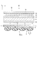
- FIG. 3 is a cross-sectional view taken along the line AA ′ of FIG.
- FIG. 4 is a diagram showing a manufacturing process of the surface light source device of this embodiment.
- the scale of the size may be varied depending on the component.
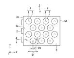
- the surface light source device 1 includes a plurality of LEDs 2 (light sources), a light guide 3 and a plurality of reflecting portions 4 as shown in FIG.
- Each reflecting portion 4 includes a mirror lens 7 and a light transmitting portion 8.
- the light guide 3 has a function of causing the light emitted from the LED 2 to enter and propagating the inside while totally reflecting between the first main surface 3a and the second main surface 3b.
- the reflection unit 4 reflects a part of light emitted from the second main surface 3b out of the light propagating through the light guide 3, changes the traveling direction of the light, and re-enters the light guide 3. And has a function of injecting from the first main surface 3a. In order to make the drawing easier to see, only 14 reflecting portions 4 are shown on the light guide 3 in the drawing, but actually, a larger number of reflecting portions 4 are provided.
- the light guide 3 is a plate made of a resin having optical transparency such as acrylic resin. 2 and 3, among the six surfaces of the light guide 3, the two main surfaces 3a and 3b facing each other are parallel, and the two end surfaces 3c and 3d facing each other are parallel.
- a plurality (three in this embodiment) of LEDs 2 are installed on one end surface 3 c of the light guide plate 3.
- the light emission surface 2 a of each LED 2 faces the end surface 3 c of the light guide plate 3. Therefore, of the two end faces 3c and 3d of the light guide plate 3, the end face 3c on the side where the LED 2 is provided becomes a light incident end face on which the light emitted from each LED 2 is incident.
- the end surface 3c on the side where the LED 2 is provided is referred to as a first end surface
- the end surface 3d on the side where the LED 2 is not provided is referred to as a second end surface.
- LED2 of this embodiment does not have directivity. Therefore, the LED 2 emits diffused light having a predetermined divergence angle.
- a plurality of reflecting portions 4 are provided on one main surface 3 b.
- the planar shape of the reflecting portion 4 viewed from the normal direction of the main surface 3b is a circle.
- the plurality of reflecting portions 4 are two-dimensionally arranged in two directions (x-axis direction and y-axis direction) orthogonal to each other in the plane of the main surface 3 b. If the distance between the centers of the adjacent reflecting portions 4 is 1 pitch, the plurality of reflecting portions 4 in adjacent rows are arranged at positions shifted by 1/2 pitch in the row direction.
- the other main surface 3a of the light guide plate 3 serves as a light emitting surface for emitting the light reflected by the plurality of reflecting portions 4, as shown in FIG.
- the main surface 3a on the side where the reflecting portion 4 is not provided is referred to as a first main surface
- the main surface 3b on the side where the reflecting portion 4 is provided is referred to as a second main surface.
- the light propagation direction in the first main surface 3a of the light guide 3 is the x-axis direction
- the direction orthogonal to the light propagation direction is the y-axis direction
- the first main surface 3a is orthogonal.
- the direction (thickness direction of the light guide 3) is defined as the z-axis direction. Therefore, “the propagation direction of light” in the present specification means the direction in which light (indicated by the dashed line arrow L) propagates while reflecting in the xz section of the light guide 3 shown in FIG. Instead, it means a direction (indicated by a solid arrow X) in which light propagates when viewed from the normal direction of the first main surface 3a of the light guide 3.
- Each reflection part 4 is comprised from the mirror lens 7 which consists of the convex lens 5 and the concave mirror 6, and the light transmissive part 8, as shown in FIG.
- the convex lens 5 is made of a light-transmitting resin such as an acrylic resin.
- the convex lens 5 is a so-called plano-convex lens in which one surface 5a is a flat surface (light emission surface) and the other surface 5b is a paraboloid (reflection surface).
- the concave mirror 6 is composed of a metal thin film with high reflectivity, such as aluminum, formed along the paraboloid 5b of the convex lens 5.
- the shape of the top part into which the light L injects is a paraboloid shape
- the shape of a side part is a cylindrical shape.
- the range in which the light L is incident through the light transmitting portion 8 may be at least parabolic, but the entire concave mirror 6 may be parabolic.
- the concave mirror 6 has a paraboloid at least in part, it has a focal point.
- the light transmitting portion 8 is a columnar member made of a resin having a light transmission property such as an acrylic resin. As will be described later, it is desirable that the light transmissive resin used for the light transmissive portion 8 has ultraviolet curability.
- the light transmissive resin used for the light transmissive portion 8 may be the same as or different from the light transmissive resin used for the convex lens 5. Therefore, the refractive index of the light transmitting resin used for the light transmitting portion 8 and the refractive index of the light transmitting resin used for the convex lens 5 may be the same or different.
- the light transmission unit 8 has a function of connecting the light guide 3 and the mirror lens 7 and guiding the light L propagating through the light guide 3 to the mirror lens 7.
- the mirror lens 7 is connected to the light guide 3 by the light transmitting portion 8 with the flat lens 5 side of the convex lens 5 facing the second main surface 3 b of the light guide 3.
- the diameter Dt of the light transmission part 8 is sufficiently smaller than the diameter of the mirror lens D1
- the light transmission part 8 has only the focal point S of the concave mirror 6 and its vicinity as shown in FIG. Is provided.
- the focal point S of the concave mirror 6 is preferably located at the interface between the light transmission part 8 and the mirror lens 7, but may be located inside the light transmission part 8, or may be guided to the light transmission part 8.
- the plane 5a of the convex lens 5 and the second main surface 3b of the light guide 3 are separated from each other, and air 9 is in the space sandwiched between the plane 5a of the convex lens 5 and the second main surface 3b of the light guide 3. Existing.
- the surface light source device 1 having the above configuration
- a method for manufacturing the surface light source device 1 having the above configuration For example, after producing the convex lens 5 made of a light-transmitting resin using a technique such as injection molding, a metal thin film such as aluminum is formed on the paraboloid 5b of the convex lens 5 using a sputtering method or the like, The mirror lens 7 is produced by forming the concave mirror 6.
- an ultraviolet curable resin (photo curable resin) is applied to one surface (plane 5a) of the mirror lens 7 to form an ultraviolet curable resin film 10 (photo curable resin film).
- the film thickness of the ultraviolet curable resin film 10 with respect to the shape of the paraboloid 5b is adjusted so that the focal point S of the concave mirror 6 is located on the upper surface, the lower surface, or the inside of the ultraviolet curable resin film 10.
- the ultraviolet ray UV is irradiated to the concave mirror 6 through the ultraviolet curable resin film 10 and the convex lens 5 with such a weak intensity that the curing of the ultraviolet curable resin film 10 does not start.
- the intensity of the ultraviolet ray UV is weak, the ultraviolet curable resin is not cured to the extent that the ultraviolet ray UV passes through the ultraviolet curable resin film 10 once.
- the reflected ultraviolet ray UV is condensed at the position of the focal point S.
- the intensity of the ultraviolet rays UV is increased at the focal point S and in the vicinity thereof, the ultraviolet curable resin film 10 is cured.
- the ultraviolet curable resin film 10 after being irradiated with the ultraviolet UV is developed.
- This remaining portion becomes a light transmission portion 8 that connects the mirror lens 7 and the light guide 3.
- the reflection part 4 is completed by the steps so far.
- the reflecting portion 4 is bonded and fixed to the light guide 3 via the light transmitting portion 8.
- the light L emitted from the LED 2 is diffused light having a certain extent.
- the light from the LED 2 travels from the first end surface 3c side to the second end surface 3d side while repeating total reflection between the first main surface 3a and the second main surface 3b of the light guide 3.
- the refractive index of the light-transmitting resin for example, acrylic resin
- the first main surface 3a and the second main surface 3b of the light guide 3 are refracted. It becomes an interface between a light-transmitting resin having a refractive index of 1.5 and air having a refractive index of 1.0.
- the critical angle at the first main surface 3a and the second main surface 3b of the light guide 3 is approximately 42 degrees. That is, light having an incident angle ⁇ of 42 degrees or more with respect to the first main surface 3a and the second main surface 3b of the light guide 3 is totally reflected on the first main surface 3a and the second main surface 3b of the light guide 3. .
- the refractive index of the light transmitting resin (for example, acrylic resin) constituting the light transmission portion 8 is 1.5. If so, the second main surface 3b of the light guide 3 is an interface between a light-transmitting resin having a refractive index of 1.5 and a light-transmitting resin having a refractive index of 1.5. In this case, total reflection does not occur on the second main surface 3 b of the light guide 3. Therefore, like the light L shown in FIG. 3, only the light L that has reached the position of the light transmitting portion 8 can pass through the light transmitting portion 8 and enter the mirror lens 7.
- the light transmitting resin for example, acrylic resin
- the light incident on the mirror lens 7 is reflected by the concave mirror 6.
- the light L reflected by the concave mirror 6 travels in a direction substantially perpendicular to the second main surface 3b of the light guide 3. To do. That is, since at least a part of the light L passes through the focal point S of the concave mirror 6, the light L reflected by the concave mirror 6 is in a direction substantially perpendicular to the second main surface 3 b of the light guide 3. proceed.
- the light L reflected by the concave mirror 6 passes through the convex lens 5 and is then emitted from the first main surface 3a of the light guide 3 only in a direction substantially perpendicular to the first main surface 3a.
- the surface light source device 1 of the present embodiment light with high directivity can be obtained in the normal direction of the first main surface 3a of the light guide 3.
- the light L passes through the focal point S of the concave mirror 6 when at least part of the light L passes through the focal point S of the concave mirror 6.
- “near the focus” means a range in which the distance from the focus is within 0 to 10% of the diameter of the mirror lens 7. That is, “near the focus” means a range surrounded by a circle having a diameter of 10% of the diameter of the mirror lens 7 with the focus at the center. For example, when the diameter of the mirror lens 7 is 100 ⁇ m, “near the focus” means a range surrounded by a circle having a diameter of 10 ⁇ m with the focus at the center.
- the surface light source device 1 of the present embodiment can obtain light with high directivity in any azimuth angle direction.
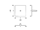
- FIG. 5 is a diagram showing the simulation result.
- the angle of the emitted light is parallel to the first main surface 3a with reference to the front direction as viewed from the first main surface 3a of the light guide 3, that is, the normal direction of the first main surface 3a is 0 degrees, and the normal direction is the reference.
- the major directions were +90 degrees and -90 degrees. 5 corresponds to the x axis (light propagation direction) in the plan view of FIG. 2, and the y axis of FIG.
- the diameter Dl of the mirror lens 7 was 100 ⁇ m
- the radius of curvature of the paraboloid of the mirror lens 7 was 50 ⁇ m
- the diameter Dt of the columnar body of the light transmitting portion 8 was 5 ⁇ m.
- the light emitted from the light guide 3 has high directivity within 20 degrees in both the x-axis direction and the y-axis direction. From this, it is estimated that the light emitted from the light guide 3 has high directivity in all azimuth angles, not limited to the x-axis direction and the y-axis direction.
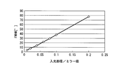
- the present inventors fixed the diameter Dl of the mirror lens 7 to 100 ⁇ m, the radius of curvature of the paraboloid of the mirror lens 7 to 50 ⁇ m, and the angle when the diameter Dt of the light transmission part 8 was changed. -The half width of the luminance profile was examined. The result is shown in FIG. 6 represents the ratio of the diameter Dt of the light transmission part 8 to the diameter Dl of the mirror lens 7, and the vertical axis of FIG. 6 represents the half-value width [degree].
- the ratio of the diameter Dt of the light transmitting portion 8 to the diameter Dl of the mirror lens 7 is preferably about 0.05.
- the ratio of the diameter Dt of the light transmission part 8 to the diameter Dl of the mirror lens 7 is preferably about 0.05.
- the diameter ratio the better.
- the diameter ratio is too small, the amount of light incident on the mirror lens 7 decreases, and the amount of light that can be extracted from the light guide 3 decreases.
- the UV light is irradiated with weak intensity through the UV curable resin film 10. Utilizing the fact that the irradiated ultraviolet ray UV is condensed at the focal point S when reflected by the concave mirror 6, the ultraviolet curable resin film 10 is left only at the focal point S and its vicinity, and this is used as the light transmitting portion 8. It is said. Therefore, the position of the light transmission part 8 with respect to the mirror lens 7 is determined in a self-aligning manner.
- the surface light source device 1 having high directivity can be manufactured with a high yield.
- a reflective film may be formed on the second end surface 3d of the light guide 3. In that case, the light reaching the second end surface 3d of the light guide 3 is reflected by the reflective film and returns toward the first end surface 3c. In the returning path, the light that has reached the light transmitting portion 8 can be taken out of the light guide 3. Further, a reflective film may be formed on the side surface of the light guide 3.
- FIG. 7 is a plan view of the surface light source device of the present embodiment, and corresponds to FIG. 2 of the first embodiment. In FIG. 7, the same components as those in FIG.
- the LED 2 is provided only on the first end surface 3 c of the light guide 3.
- a plurality of LEDs 2 are also provided on the second end surface 3 d of the light guide 3. Is provided.
- the number of the reflection parts 4 provided in the light guide 3 is the same as in the first embodiment.
- the surface light source device 12 of the present embodiment it is possible to obtain the same effect as that of the first embodiment that emitted light having high directivity can be obtained.
- the number of the reflection parts 4 is the same as that of the first embodiment, the light from the LED 2 provided on the first end surface 3c of the light guide 3 and the LED 2 provided on the second end surface 3d Since the light can be extracted by the same reflecting portion 4, an efficient surface light source device can be provided.
- FIG. 8 is a plan view of the surface light source device of this embodiment, and corresponds to FIG. 2 of the first embodiment. In FIG. 8, the same components as those in FIG.
- the circular reflecting portion 4 is provided when viewed from the normal direction of the second main surface 3b of the light guide 3.
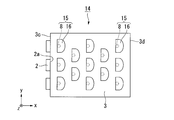
- the surface light source device 14 of the present embodiment is provided with a substantially semicircular reflecting portion 15 when viewed from the normal direction of the second main surface 3b of the light guide 3, as shown in FIG. Yes.
- the light transmission part 8 is comprised with the cylindrical body similarly to 1st Embodiment. Therefore, the planar shape of the mirror lens 16 is substantially semicircular. Further, the mirror lens 16 is arranged so that the straight side of the semicircle that is the planar shape of the mirror lens 16 faces the first end surface 3 c of the light guide 3.
- the surface light source device 14 of the present embodiment it is possible to obtain the same effect as that of the first embodiment that emitted light having high directivity can be obtained. If only the light traveling from the LED 2 provided on the first end surface 3c of the light guide 3 to the second end surface 3d is used, the circular mirror lens 7 as in the first embodiment is used as in the present embodiment. Of these, half of the light guide 3 on the second end face 3d side is sufficient. According to the configuration of the present embodiment, since the area occupied by the mirror lens 16 is smaller than that of the first embodiment, the arrangement density of the mirror lenses 16 can be increased. As a result, the light extraction efficiency can be increased.
- FIG. 9 is a plan view of the surface light source device of this embodiment, and corresponds to FIG. 2 of the first embodiment. In FIG. 9, the same components as those in FIG.
- the circular reflection part 4 was provided seeing from the normal line direction of the 2nd main surface 3b of the light guide 3.
- the surface light source device 18 of the present embodiment is provided with a regular hexagonal reflection portion 19 on the second main surface 3 b of the light guide 3 when viewed from the normal direction.
- the light transmission part 8 is comprised with the cylindrical body similarly to 1st Embodiment. Therefore, the planar shape of the mirror lens 20 is a regular hexagon.
- the mirror lens 20 of the present embodiment is obtained by simply cutting the edge of a circular mirror lens similar to the first embodiment into a regular hexagon, and the top of the mirror lens 20 is the same as that of the first embodiment. Has a parabolic surface. Adjacent mirror lenses 20 are arranged in close contact so that regular hexagonal sides are in contact with each other.
- the plurality of mirror lenses 20 are formed of an integral light transmissive resin.
- the surface light source device 18 of the present embodiment it is possible to obtain the same effect as that of the first embodiment that emitted light having high directivity can be obtained.
- the arrangement density of the mirror lenses 20 can be increased.
- the light extraction efficiency can be increased.
- the plurality of mirror lenses 20 are formed of an integral light transmissive resin, handling becomes easy when the reflecting portion 19 is manufactured.
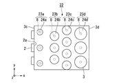
- FIG. 10 is a plan view of the surface light source device of this embodiment, and corresponds to FIG. 2 of the first embodiment. In FIG. 10, the same components as those in FIG.
- the dimensions of the plurality of reflecting portions 4 are equal, and the plurality of reflecting portions 4 are arranged uniformly over the entire light guide 3.
- the shapes of the reflecting portions 23a to 23d are all circular, but the dimensions of the plurality of reflecting portions 23a to 23d are different. Further, the arrangement of the plurality of reflecting portions 23a to 23d on the light guide 3 is uneven.
- the diameter of the mirror lens 24a located near the first end face 3c of the light guide 3 close to the LED 2 is small, and the diameter of the mirror lens 24d located near the second end face 3d of the light guide 3 far from the LED 2 Is set larger. Further, in all the reflecting portions 23a to 23d, the ratio of the diameter of the light transmitting portion 8 to the diameter of the mirror lenses 24a to 24d is equal. Therefore, the diameter of the light transmission part 8 located near the first end face 3c of the light guide 3 is set small, and the diameter of the light transmission part 8 located near the second end face 3d of the light guide 3 is set large.
- the arrangement density of the mirror lenses 24a located near the first end face 3c of the light guide 3 close to the LED 2 is small, and the arrangement density of the mirror lenses 24d located near the second end face 3d of the light guide 3 far from the LED 2 is low. It is set large.
- the surface light source device 22 of the present embodiment it is possible to obtain the same effect as that of the first embodiment that emitted light having high directivity can be obtained.
- the light emitted from the LED 2 travels from the first end surface 3c to the second end surface 3d of the light guide 3, when the plurality of reflecting portions are evenly arranged, the reflecting portion on the side closer to the LED 2 is first. In some cases, a large amount of light is extracted, and the amount of light extracted gradually decreases as the light advances. As a result, the luminance may be non-uniform in the plane.
- the luminance in the plane can be made uniform. it can.
- FIG. 11 is a cross-sectional view of the surface light source device of the present embodiment, and corresponds to FIG. 3 of the first embodiment. In FIG. 11, the same components as those in FIG.
- the convex lens 5 constituting the mirror lens 7 is connected to the light guide 3 via the light transmitting portion 8.
- the surface light source device 26 of the present embodiment has a hollow inside the concave mirror 6 and no convex lens.
- the light transmission part 27 of this embodiment does not transmit light linearly.
- the light transmitting portion 27 scatters the light L propagating through the light guide 3 and is composed of a scatterer that emits the light L toward the concave mirror 6.
- the light transmission part 27 is arranged so that the focal point S of the concave mirror 6 is located inside.
- the concave mirror 6 is supported by an arbitrary support means with a predetermined distance from the light guide 3.
- a plurality of concave mirrors 6 may be formed in close contact with each other, and the entirety thereof may be supported between the light guide 3 and a spacer or the like.
- the surface light source device 26 of the present embodiment only the light that has reached the light transmission part 27 out of the second main surface 3b of the light guide 3 is scattered inside the light transmission part 27 and the internal space of the concave mirror 6. To be taken out. Thereafter, the light L is reflected by the concave mirror 6, passes through the light guide 3, and is extracted in the front direction of the light guide 3. In this manner, similarly to the first to fifth embodiments, the surface light source device 26 of this embodiment can obtain emitted light with high directivity.
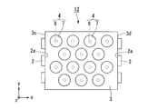
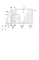
- FIG. 12 is a perspective view of the surface light source device of the present embodiment, and corresponds to FIG. 1 of the first embodiment.
- FIG. 13 is a plan view of the surface light source device of this embodiment, and corresponds to FIG. 2 of the first embodiment.
- the same reference numerals are given to the same components as those in FIG. 1 and FIG.
- the surface light source device 29 of the present embodiment includes a light source 30, a light guide 3, and a plurality of reflecting portions 31, as shown in FIG.
- the light source 30 includes an LED 32, a wedge-shaped prism 33, and a prism sheet 34.
- the reflection part 4 of the first embodiment has a circular planar shape when viewed from the normal direction of the light guide 3.
- the planar shape viewed from the normal direction of the light guide 3 extends in a band shape in a direction (y-axis direction) perpendicular to the light propagation direction.
- the LED 2 having no directivity is used.
- the LED 32 may not have directivity, but the light source 30 is parallel to the first main surface 3a of the light guide 3 as shown in FIG.
- the light L having directivity is emitted in a direction perpendicular to the propagation direction (y-axis direction).
- the LED 32 is disposed on an end surface 33 a of a wedge-shaped prism 33 having a right-angled triangle when viewed from the normal direction of the light guide 3, and emits light toward the inside of the wedge-shaped prism 33.
- the wedge-shaped prism 33 has dimensions in a direction (x-axis direction) parallel to the light propagation direction along a direction (y-axis direction) parallel to the first main surface 3a of the light guide 3 and perpendicular to the light propagation direction. Is a wedge-shaped light guide member that becomes gradually smaller.
- the light L emitted from the LED 32 travels from the end surface 33a of the wedge-shaped prism 33 toward an acute tip while repeating total reflection between the inclined surface 33b and the vertical surface 33c of the wedge-shaped prism 33. At this time, the incident angle of light with respect to the vertical surface 33c becomes smaller as the number of total reflections increases. Only light whose incident angle with respect to the vertical surface 33c is smaller than the critical angle is emitted from the vertical surface 33c of the wedge-shaped prism 33 to the outside. In this way, light having high directivity is emitted from the wedge prism 33.
- a prism sheet 34 having a plurality of prisms 35 is disposed so as to face the vertical surface 33 c of the wedge-shaped prism 33.
- the light L is refracted once when entering the vertical surface 34a, and refracted once when emitted from the inclined surface 35a of each prism 35.
- the traveling direction of the light L is perpendicular to the first end surface 3 c of the light guide 3 by appropriately designing the shape of the prism 35 according to the incident angle of the light L with respect to the vertical surface 34 a of the prism sheet 34. Can be directed in any direction.
- the light source 30 by using the light source 30 described above, light having high directivity is transmitted from the first end surface 3c of the light guide 3 in the direction perpendicular to the light propagation direction in the light guide 3 (y-axis direction). It can be made incident. Therefore, it is not necessary for the reflecting portion 31 to have a function of improving directivity in a direction (y-axis direction) perpendicular to the light propagation direction. Therefore, in this embodiment, a lenticular mirror lens 36 extending in a direction (y-axis direction) perpendicular to the light propagation direction may be used.
- the mirror lens 36 of the present embodiment has a curvature in the light propagation direction (x-axis direction), is parallel to the first main surface 3a of the light guide 3 and is perpendicular to the light propagation direction (y-axis direction). ) Has no curvature.
- the focal point of the concave mirror 37 constituting the mirror lens 36 is linear in a direction parallel to the first main surface 3a of the light guide 3 and perpendicular to the light propagation direction (y-axis direction).
- the light transmission portion 38 extends long in a direction (y-axis direction) parallel to the first main surface 3a of the light guide 3 and perpendicular to the light propagation direction.
- the linear focal point of the mirror lens 36 is located on the surface or inside of the light transmission part 38.
- the light transmission part 38 is provided only at the focal point and its vicinity, and only the light passing through the focal point and its vicinity is reflected by the concave mirror 37 of the mirror lens 36 as in the first embodiment. is there. Therefore, as described in the first embodiment, light having high directivity in the light propagation direction (x-axis direction) can be obtained by the action of the reflecting portion 31. In this manner, as in the first to sixth embodiments, the surface light source device 29 of the present embodiment can obtain emitted light having high directivity in any direction.
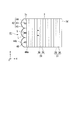
- FIG. 14 is a perspective view of the surface light source device of this embodiment, and corresponds to FIG. 1 of the first embodiment.
- FIG. 15 is a plan view of the surface light source device of the present embodiment, and corresponds to FIG. 2 of the first embodiment.
- the same reference numerals are given to the same components as those in FIG. 1 and FIG.
- the reflection part 31 of the present embodiment is the same as the reflection part 31 of the seventh embodiment.
- the surface light source device 40 of this embodiment is parallel to the first main surface 3a of the light guide 3 and perpendicular to the light propagation direction (y-axis direction), as in the seventh embodiment.
- the configuration of the light source 41 for emitting light having high directivity in the direction (y-axis direction) parallel to the first main surface 3a of the light guide 3 and perpendicular to the light propagation direction is the seventh. Different from the embodiment.
- the light source 41 has a configuration in which a plurality of light emitting units 42 are arranged in a line in a direction (y-axis direction) perpendicular to the light propagation direction.
- the light emitting unit 42 includes an LED 43, a cylindrical lens 44, and a mirror 45.
- the cylindrical lens 44 is a so-called plano-convex lens having one convex surface and the other flat surface. Since light is emitted from the flat surface 44a, the flat surface 44a is hereinafter referred to as a light emitting surface.
- the convex surface 44b has a curved surface that is gently curved and two flat surfaces that are continuous with both ends of the curved surface.
- the curved surface of the convex surface 44b has a curved shape having a focal point S as shown in FIG.
- the cross-sectional shape of the curved surface is a parabolic shape.
- the curved surface is a linear shape. That is, the curved surface of the cylindrical lens 44 is a paraboloid that is curved in the xy plane and not curved in the xy plane.
- a mirror 45 is provided along the curved surface of the cylindrical lens 44.
- the shape of the mirror 45 is a paraboloid reflecting the shape of the curved surface. Therefore, the position of the focal point S of the mirror 45 coincides with the position of the focal point S of the cylindrical lens 44.
- the focal point is indicated by point S in FIG.
- the light exit surface 44a of the cylindrical lens 44 is provided with a groove 46 having a depth sufficient to allow the LED 43 to be inserted therein.
- the cross-sectional shape of the bottom of the groove 46 when the cylindrical lens 44 is cut along the xy plane is rounded into an arc.
- a rod-shaped LED 43 is arranged inside the groove 46.
- the LED 43 is arranged with its light emitting surface facing the mirror 45.
- the LED 43, the mirror 45, and the cylindrical lens 44 are set such that their positional relationship, size, shape, and the like are set so that the focal point S of the mirror 45 and the cylindrical lens 44 is located on the light emitting surface of the LED 43.
- the LED 43 Since the light emitting surface of the LED 43 faces the mirror 45, almost all of the light emitted from the light emitting surface of the LED 43 is directed to the mirror 45, reflected by the mirror 45, and then emitted from the light emitting surface 44a of the cylindrical lens 44.
- the LED 43 is not particularly directional, and a general LED that emits light at a predetermined diffusion angle can be used.
- the light L emitted from the light emitting surface of the LED 43 is directed to the mirror 45 with a predetermined diffusion angle and reflected by the mirror 45. Since the position of the light emitting surface of the LED 43 coincides with the focal point S, the light L emitted from the LED 43 is incident on the mirror 45 at any angle. Travels in a direction parallel to the optical axis. Accordingly, the diffused light immediately after being emitted from the light emitting surface of the LED 43 is reflected by the mirror 45 to be converted into light that is parallelized in the y-axis direction, that is, light that has high directivity in the y-axis direction, and a cylindrical lens. The light exits from the light exit surface 44 a of 44 and enters the light guide 3.
- the light transmitting portion 38 is provided only at the focal point and the vicinity thereof, and only the light passing through the focal point and the vicinity thereof is reflected by the mirror lens 36 as in the first embodiment. Therefore, as described in the first embodiment, light having high directivity in the light propagation direction (x-axis direction) can be obtained by the action of the reflecting portion 31. In this manner, similarly to the first to sixth embodiments, the surface light source device of this embodiment can obtain emitted light with high directivity.
- the light source 41 of this embodiment is provided with the cylindrical lens 44 inside the mirror 45, the cylindrical lens 44 does not necessarily need to be provided and the inside of the mirror 45 may be hollow.
- the ninth embodiment of the present invention will be described below with reference to FIG.
- a display device including the surface light source device of the above embodiment is shown.
- the present embodiment is an example of a liquid crystal display device that includes the surface light source device of the first embodiment as a backlight.
- the liquid crystal display device 48 of this embodiment includes a backlight 49 (surface light source device), a first polarizing plate 50, a liquid crystal panel 51, a second polarizing plate 52, and a viewing angle widening film. 53.
- the liquid crystal panel 51 is schematically illustrated as a single plate. The observer views the display from the upper side of the liquid crystal display device 48 in FIG. 16 in which the viewing angle widening film 53 is arranged. Therefore, in the following description, the side on which the viewing angle widening film 53 is disposed is referred to as a viewing side, and the side on which the backlight 49 is disposed is referred to as a back side.
- the light emitted from the backlight 49 is modulated by the liquid crystal panel 51, and a predetermined image, character, or the like is displayed by the modulated light.
- the angle distribution of the emitted light becomes wider than before entering the viewing angle widening film 53, and the light is widened. Is injected from. Thereby, the observer can visually recognize the display with a wide viewing angle.
- the liquid crystal panel 51 for example, an active matrix transmissive liquid crystal panel can be used.
- the liquid crystal panel is not limited to an active matrix transmissive liquid crystal panel.
- each pixel does not include a switching thin film transistor (Thin Film Transistor, hereinafter abbreviated as TFT).
- TFT Thin Film Transistor
- a simple matrix type liquid crystal panel may be used. Since a well-known general liquid crystal panel can be used for the liquid crystal panel 51, detailed description of a structure is abbreviate
- a viewing angle widening film 53 is disposed on the viewing side of the liquid crystal display device 48.
- the viewing angle widening film 53 includes a base material 54, a plurality of light diffusion portions 55 formed on one surface of the base material 54 (a surface opposite to the viewing side), and a black layer 56 formed on one surface of the base material 54. (Light absorption layer).
- the viewing angle widening film 53 is disposed on the second polarizing plate 52 in a state where the side where the light diffusing portion 55 is provided faces the second polarizing plate 52 and the base 54 side faces the viewing side.
- the base material 54 a base material made of a transparent resin such as a triacetyl cellulose (TAC) film is preferably used.
- the light diffusing portion 55 is made of an organic material having light transmissivity and photosensitivity such as acrylic resin and epoxy resin.
- the light diffusing unit 55 has a circular horizontal cross section (xy cross section).
- the light diffusion part 55 has a small area on the surface on the base material 54 side serving as the light emission end face, and a large area on the surface opposite to the base material 54 serving as the light incident end face, and is opposite to the base material 54 from the base material 54 side.
- the area of the horizontal section gradually increases toward the side.
- the light diffusing portion 55 has a so-called reverse-tapered truncated cone shape when viewed from the base 54 side.
- the light diffusion portion 55 is a portion that contributes to light transmission in the viewing angle widening film 53. That is, the light incident on the light diffusing portion 55 is totally reflected on the tapered side surface of the light diffusing portion 55, guided in a state of being substantially confined inside the light diffusing portion 55, and diffused in all directions It is injected at.
- the black layer 56 is formed in a region other than the formation region of the plurality of light diffusion portions 55 in the surface of the base 54 on the side where the light diffusion portions 55 are formed.
- the black layer 56 is made of an organic material having light absorption and photosensitivity such as a black resist.
- the screen is not displayed in a liquid crystal display device using a conventional backlight having no directivity. Color misregistration occurs when viewed from the front direction and when viewed from the oblique direction.
- the backlight 49 including the surface light source device 1 of the first embodiment having high directivity in the front direction is used. Light is transmitted only through a small angle range. Thereafter, since the light is diffused in all directions by the viewing angle widening film 53, the observer can see a high-quality image with little color shift when viewed from any direction.
- the liquid crystal display device 58 of the present embodiment includes a backlight 49 (surface light source device), a liquid crystal element 59, and a light emitting element 60, as shown in FIG.
- a red subpixel 61R for displaying with red light a green subpixel 61G for displaying with green light, and a blue subpixel 61B for displaying with blue light are arranged adjacent to each other.
- These three sub-pixels 61R, 61G, and 61B constitute one pixel that is a minimum unit that constitutes a display.
- the backlight 49 emits excitation light L1 that excites the phosphor layers 62R, 62G, and 62B of the light emitting element 60.
- the backlight 49 emits ultraviolet light or blue light as the excitation light L1.
- the liquid crystal element 59 modulates the transmittance of the excitation light L1 emitted from the backlight 49 for each of the subpixels 61R, 61G, and 61B. Excitation light L1 modulated by the liquid crystal element 59 is incident on the light-emitting element 60, and the phosphor layers 62R, 62G, and 62B are excited and emitted light is emitted to the outside. Therefore, in the present embodiment, the upper side of the liquid crystal display device 58 shown in FIG.
- the liquid crystal element 59 has a configuration in which a liquid crystal layer 65 is sandwiched between a first transparent substrate 63 and a second transparent substrate 64.
- the second transparent substrate 64 positioned on the front side as viewed from the observer also serves as the substrate of the light emitting element 60.
- a first transparent electrode 66 is formed for each subpixel on the inner surface (the liquid crystal layer 65 side surface) of the first transparent substrate 63, and an alignment film (not shown) is formed so as to cover the first transparent electrode 66. Yes.
- a first polarizing plate 67 is provided on the outer surface of the first transparent substrate 63 (the surface opposite to the liquid crystal layer 65 side).
- the first transparent substrate 63 a substrate made of glass, quartz, plastic, or the like that can transmit excitation light can be used.
- a transparent conductive material such as indium tin oxide (Indium Tin Oxide, hereinafter abbreviated as ITO) is used.
- ITO Indium Tin Oxide
- the first polarizing plate 67 a conventional externally attached polarizing plate can be used.
- the phosphor layer 62 and the first light absorption layer 68 are laminated in this order from the substrate side on the inner surface (the surface on the liquid crystal layer 65 side) of the second transparent substrate 64.
- the phosphor material constituting the phosphor layer 62 has a different emission wavelength band for each subpixel.
- the red subpixel 61R is provided with a phosphor layer 62R made of a phosphor material that absorbs ultraviolet light and emits red light.
- the green subpixel 61G is provided with a phosphor layer 62G made of a phosphor material that absorbs ultraviolet light and emits green light.
- the blue subpixel 61B is provided with a phosphor layer 62B made of a phosphor material that absorbs ultraviolet light and emits blue light.
- the red sub-pixel 61R and the green sub-pixel 61G are made of phosphor materials that absorb blue light and emit red light and green light, respectively.
- the blue sub-pixel 61B is provided with a light diffusing layer that diffuses the blue light, which is the excitation light, without converting the wavelength and emits it to the outside instead of the phosphor layer. It is done.
- a second polarizing plate 69 is formed on the inner surface of the second transparent substrate 64 so as to cover the first light absorption layer 68, and a second transparent electrode 70 and an alignment film (not shown) are formed on the surface of the second polarizing plate 69. ) Are stacked.
- the second polarizing plate 69 is a so-called in-cell polarizing plate that is made using a coating technique or the like in the manufacturing process of the liquid crystal element 59.
- a transparent conductive material such as ITO is used for the second transparent electrode 70.
- a second light absorption layer 71 is formed on the outer surface side of the second transparent substrate 64.
- the first light absorption layer 68 provided on the inner surface of the second transparent substrate 64 is for suppressing a decrease in contrast due to leakage of the excitation light L ⁇ b> 1 from the backlight 49.
- the second light absorption layer 71 provided on the outer surface of the second transparent substrate 64 is for suppressing a decrease in contrast due to external light.
- an ordinary liquid crystal display device has a color shift when viewed from an oblique direction.
- the fluorescence excitation type liquid crystal display device 54 of the present embodiment uses an ultraviolet or blue light surface light source device having high directivity as the backlight 44, and uses the ultraviolet light or blue light as the phosphor layer 58. Color conversion. At this time, the light of each color is isotropically emitted from the phosphor layer 58, so that the observer can see a high-quality image with little color shift when viewed from any direction.
- FIG. 18 is a front view illustrating a schematic configuration of a liquid crystal display device which is a configuration example of the display device.
- the liquid crystal television 73 of this configuration example includes the liquid crystal display device 48 of the ninth embodiment or the liquid crystal display device 58 of the tenth embodiment as a display screen.
- a liquid crystal panel is disposed on the viewer side (front side in FIG. 18), and a backlight (surface light source device) is disposed on the side opposite to the viewer (back side in FIG. 18).
- the liquid crystal television 73 of this configuration example is a high-quality liquid crystal television by including the liquid crystal display devices 48 and 58 of the above embodiment.
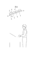
- FIG. 19 is a diagram illustrating a schematic configuration of the illumination device. Since the basic configuration of the illuminating device is substantially the same as that of the surface light source device of the first embodiment, the same reference numerals are given to the same components in FIG. 19 as those in FIG. 3 of the first embodiment, and description thereof is omitted.
- the illumination device 75 of this configuration example includes an LED 2, a light guide 3, and a plurality of reflection units 4. That is, the illumination device 75 is the same as the surface light source device 1 of the first embodiment. If the illuminating device 75 is installed with the first main surface of the light guide 3 directed obliquely downward, the light L having high directivity can be emitted obliquely downward of the illuminating device 75.
- the lighting device 75 of the present configuration example is installed near the ceiling of a hall, for example, light with high directivity is emitted downward from the lighting device 75, so that it can be used as a spotlight.
- the shape of the concave mirror constituting the reflecting portion is a paraboloid.
- the shape of the concave mirror that can be used in the above embodiment is not necessarily limited to a paraboloid, and may be a conical curved surface as a concept including a paraboloid.
- a curve indicating the shape of a cross section passing through the apex of the conical curved surface is called a quadratic curve.
- a quadratic curve is a curve obtained from a cross section obtained by cutting a cone at an arbitrary plane.
- the quadratic curve can be expressed by the following equations (1) and (2).
- the shape of the quadratic curve changes depending on the value of the conic coefficient k in the equations (1) and (2).
- a concave mirror having a cross-sectional shape of these quadratic curves can be used.
- attains should just be a conical curved surface at least, the area
- the aspect of the present invention can be used for various display devices such as a liquid crystal display device, a surface light source device used for this type of display device, or various illumination devices.
Landscapes
- Physics & Mathematics (AREA)
- Nonlinear Science (AREA)
- General Physics & Mathematics (AREA)
- Optics & Photonics (AREA)
- Mathematical Physics (AREA)
- Chemical & Material Sciences (AREA)
- Crystallography & Structural Chemistry (AREA)
- Planar Illumination Modules (AREA)
- Liquid Crystal (AREA)
Abstract
面光源装置は、光源と、導光体と、反射部と、を備える。導光体は、第1主面と第2主面を有し、光源から射出された光を入射させ、第1主面と第2主面との間で全反射させて内部を伝播させる。反射部は、導光体の内部を伝播する光のうち、第2主面から射出される一部の光を反射させて光の進行方向を変え、導光体に再度入射させて第1主面から射出させる。反射部は、凹面ミラーと、光透過部と、を備える。凹面ミラーは、導光体の第2主面と対向する反射面を有し、光の伝播方向に平行かつ第2主面に垂直な平面内にて焦点を有する形状である。光透過部は、導光体の第2主面に接するとともに、凹面ミラーの焦点を含む位置に設けられ、導光体の内部を伝播して第2主面に到達した光のうち、焦点もしくは焦点の近傍を通る光を透過させて凹面ミラーの反射面に向けて射出させる。
Description
本発明は、面光源装置およびその製造方法、表示装置、照明装置に関する。
本願は、2011年4月22日に、日本に出願された特願2011-095978号に基づき優先権を主張し、その内容をここに援用する。
本願は、2011年4月22日に、日本に出願された特願2011-095978号に基づき優先権を主張し、その内容をここに援用する。
表示装置の一例として、面光源装置から射出される光を利用して表示を行う透過型液晶表示装置が知られている。この種の液晶表示装置は、液晶パネルと、液晶パネルの背面側に配置された面光源装置と、を有している。従来の面光源装置は、発光ダイオード(Light Emitting Diode, 以下、LEDと略記する)等の光源と導光板とを備えている。この面光源装置では、光源から射出された光を導光板の内部で伝播させ、導光板の全面から射出させる。以下、本明細書では、表示パネルの背面側に設けられる面光源装置のことをバックライトと記す場合もある。
バックライトからの射出光に指向性を持たせる手法として、光発生装置と、導光板と、マイクロプリズムと、マイクロレンズアレイと、を備えたバックライト装置が開示されている(下記の特許文献1参照)。このバックライト装置において、光発生装置から射出された光は、導光板の内部を伝播する間にマイクロプリズムに入射すると、マイクロプリズムで反射して進行方向が変わり、正面に取り出される。さらに、マイクロプリズムから射出された光は、マイクロレンズアレイに入射し、各マイクロレンズにより平行度が高められてバックライト装置から射出される。
特許文献1に記載されたバックライト装置において、マイクロレンズにより指向性を高めるためには、マイクロレンズの焦点位置もしくは焦点位置の近傍にマイクロプリズムが配置されている必要がある。したがって、マイクロプリズムとマイクロレンズアレイとの間のアライメントに高い精度が要求される。アライメントの精度が低い場合には光の平行度を高めることができず、十分な指向性が得られない。また、このバックライト装置は部品点数が多く、部材コスト、組立コスト等を含む製造コストが高騰する。
本発明の態様は、上記の課題を解決するためになされたものであって、指向性の高い光が得られる面光源装置を提供することを目的とする。低コストの面光源装置を提供することを目的とする。この種の面光源装置を製造する方法を提供することを目的とする。この種の面光源装置を備えた表示装置および照明装置を提供することを目的とする。
上記の目的を達成するために、本発明の一態様における面光源装置は、光源と、第1主面と第2主面を有し、前記光源から射出された光を前記第1主面と前記第2主面との間で全反射させて内部を伝播させる導光体と、前記導光体の内部を伝播する光のうち、前記第2主面から射出される一部の光を反射させて前記光の進行方向を変え、前記導光体に再度入射させて前記第1主面から射出させる反射部と、を備え、前記反射部は、前記導光体の前記第2主面と対向する反射面を有し、前記光の伝播方向に平行かつ前記第2主面に垂直な平面内にて焦点を有する形状の凹面ミラーと、前記導光体の前記第2主面に接するとともに前記凹面ミラーの焦点を含む位置に設けられ、前記導光体の内部を伝播して前記第2主面に到達した光のうち、前記焦点もしくは前記焦点の近傍を通る光を透過させて前記凹面ミラーの反射面に向けて射出させる光透過部と、を備える。
本発明の一態様における面光源装置は、さらに、前記凹面ミラーの窪みに凸レンズを備え、前記導光体と前記凸レンズとの互いに対向する面同士が離間しており、前記導光体と前記凸レンズとが前記光透過部を介して連結されていてもよい。
本発明の一態様における面光源装置は、前記導光体の前記第2主面の法線方向から見た前記凹面ミラーの平面形状が円形であってもよい。
本発明の一態様における面光源装置は、前記光源が、互いに対向する前記導光体の第1端面と第2端面とに設けられていてもよい。
本発明の一態様における面光源装置は、前記導光体の前記第2主面の法線方向から見た前記凹面ミラーの平面形状が略半円形であってもよい。
本発明の一態様における面光源装置は、前記光源が前記導光体の第1端面に設けられ、前記凹面ミラーが、前記平面形状における略半円の直線側が前記第1端面を向くように配置されていてもよい。
本発明の一態様における面光源装置は、前記凹面ミラーが、前記光の伝播方向に平行な方向に曲率を持ち、前記光の伝播方向に垂直かつ前記第2主面に平行な方向には曲率を持たず、前記光透過部が、前記光の伝播方向に垂直かつ前記第2主面に平行な方向に延在していてもよい。
本発明の一態様における面光源装置は、前記凹面ミラーが複数設けられていてもよい。
本発明の一態様における面光源装置は、前記複数の凹面ミラーのうち、少なくとも一部の凹面ミラーの平面寸法が他の凹面ミラーの平面寸法と異なっていてもよい。
本発明の一態様における面光源装置は、前記複数の凹面ミラーの配置密度が、前記光の伝播方向に沿って順次高くなっていてもよい。
本発明の一態様における面光源装置は、前記導光体の前記第2主面の法線方向から見た前記凹面ミラーの平面形状が多角形であり、隣り合う前記多角形同士が密着して配置されていてもよい。
本発明の一態様における面光源装置は、前記光源が、射出光に対して、前記光の伝播方向に垂直かつ前記第2主面に平行な方向に指向性を付与してもよい。
本発明の一態様における面光源装置は、前記光源が、前記光の伝播方向に垂直かつ前記第2主面に平行な方向に沿って前記光の伝播方向に平行な方向の寸法が順次小さくなる楔状の導光部材を備えていてもよい。
本発明の一態様における面光源装置は、前記光源が、発光素子と前記発光素子から射出された光を反射するミラーとを備え、前記ミラーが、前記導光体の前記第2主面に平行な平面内にて焦点を有し、前記発光素子は、発光面上に前記焦点が位置するように配置され、前記発光素子からの光が前記ミラーを介して前記導光体に入射されてもよい。
本発明の他の態様における面光源装置の製造方法は、凸レンズの一つの面に、焦点を有する凹面ミラーを設けてなるミラーレンズを作製することと、前記凸レンズの他の面に光硬化樹脂を塗布し、膜内に前記焦点が位置するように光硬化樹脂膜を形成することと、前記凹面ミラーに前記光硬化樹脂膜および前記凸レンズを介して前記光硬化樹脂膜の硬化が開始しない強度で光を照射することと、光照射後の前記光硬化樹脂膜を現像し、前記光硬化樹脂膜のうち、前記焦点および前記焦点の近傍の部分のみを残存させ、その残存部分を光透過部とすることと、前記光透過部を介して前記ミラーレンズを導光体に固定することと、前記導光体に光源を設置することと、を備える。
本発明のさらに他の態様における表示装置は、上述の面光源装置と、前記面光源装置からの射出光を用いて表示を行う表示素子と、を備える。
本発明のさらに他の態様における照明装置は、本発明の面光源装置を備える。
本発明の態様によれば、指向性の高い光が得られる面光源装置を提供することができる。低コストの面光源装置を提供することができる。また、この種の面光源装置を製造する方法を提供することができる。また、この種の面光源装置を備えた表示装置および照明装置を提供することができる。
[第1実施形態]
以下、本発明の第1実施形態について、図1~図6を用いて説明する。
本実施形態では、例えば液晶表示装置のバックライトとして用いて好適な面光源装置の一例を示す。
図1は、本実施形態の面光源装置を示す斜視図である。図2は、本実施形態の面光源装置を示す平面図である。図3は、図2のA-A’線に沿う断面図である。図4は、本実施形態の面光源装置の製造プロセスを示す図である。
なお、以下の各図面においては各構成要素を見やすくするため、構成要素によって寸法の縮尺を異ならせて示すことがある。
以下、本発明の第1実施形態について、図1~図6を用いて説明する。
本実施形態では、例えば液晶表示装置のバックライトとして用いて好適な面光源装置の一例を示す。
図1は、本実施形態の面光源装置を示す斜視図である。図2は、本実施形態の面光源装置を示す平面図である。図3は、図2のA-A’線に沿う断面図である。図4は、本実施形態の面光源装置の製造プロセスを示す図である。
なお、以下の各図面においては各構成要素を見やすくするため、構成要素によって寸法の縮尺を異ならせて示すことがある。
本実施形態の面光源装置1は、図1に示すように、複数のLED2(光源)と、導光体3と、複数の反射部4と、を備えている。各反射部4は、ミラーレンズ7と、光透過部8と、から構成されている。導光体3は、LED2から射出された光を入射させ、第1主面3aと第2主面3bとの間で全反射させつつ内部を伝播させる機能を有する。反射部4は、導光体3の内部を伝播する光のうち、第2主面3bから射出される一部の光を反射させて光の進行方向を変え、導光体3に再度入射させて第1主面3aから射出させる機能を有する。なお、図面を見やすくするため、図面では導光体3上に14個の反射部4のみを示しているが、実際にはより多数の反射部4が設けられている。
導光体3は、アクリル樹脂等の光透過性を有する樹脂からなる板体である。図2および図3に示すように、導光体3の6つの面のうち、互いに対向する2つの主面3a,3bは平行であり、互いに対向する2つの端面3c,3dは平行である。導光板3の一つの端面3cには、複数(本実施形態では3個)のLED2が設置されている。各LED2の光射出面2aは導光板3の端面3cに対向している。したがって、導光板3の2つの端面3c、3dのうち、LED2が設けられた側の端面3cは、各LED2からの射出光を入射させる光入射端面となる。以下、LED2が設けられた側の端面3cを第1端面と称し、LED2が設けられていない側の端面3dを第2端面と称する。また、本実施形態のLED2は指向性を有していない。したがって、LED2は、所定の拡がり角を有する拡散光を射出する。
導光板3の2つの主面3a,3bのうち、一方の主面3bには複数の反射部4が設けられている。主面3bの法線方向から見た反射部4の平面形状は円形である。複数の反射部4は、図2に示すように、主面3bの面内において直交する2つの方向(x軸方向、y軸方向)に2次元的に配置されている。隣り合う反射部4の中心間の距離を1ピッチとすると、隣り合う行の複数の反射部4は、行方向に1/2ピッチずつずれた位置に配置されている。また、導光板3の他方の主面3aは、図3に示すように、複数の反射部4で反射した光を射出させる光射出面となる。以下、反射部4が設けられていない側の主面3aを第1主面と称し、反射部4が設けられた側の主面3bを第2主面と称する。
なお、本実施形態において、導光体3の第1主面3aの面内における光の伝播方向をx軸方向、光の伝播方向と直交する方向をy軸方向、第1主面3aと直交する方向(導光体3の厚み方向)をz軸方向、と定義する。したがって、本明細書における「光の伝播方向」とは、図3に示す導光体3のxz断面内で光(1点鎖線の矢印Lで示す)が反射しつつ伝播する方向を意味するのではなく、導光体3の第1主面3aの法線方向から見て光が伝播する方向(実線の矢印Xで示す)を意味する。
各反射部4は、図3に示すように、凸レンズ5と凹面ミラー6とからなるミラーレンズ7と、光透過部8と、から構成されている。凸レンズ5は、例えばアクリル樹脂等の光透過性を有する樹脂から構成されている。凸レンズ5は、一方の面5aが平面(光射出面)、他方の面5bが放物面(反射面)となったレンズ、いわゆる平凸レンズである。
凹面ミラー6は、凸レンズ5の放物面5bに沿って形成されたアルミニウム等の反射率が高い金属薄膜から構成されている。本実施形態では、xz平面で切断した凹面ミラー6のうち、光Lが入射する頂部の形状は放物面状であり、側部の形状は円筒状である。このように、凹面ミラー6のうち、光透過部8を通して光Lが入射する範囲が少なくとも放物面状であれば良いが、凹面ミラー6の全体が放物面状であっても良い。このように、凹面ミラー6は、少なくとも一部に放物面を有しているため、焦点を有している。
光透過部8は、アクリル樹脂等の光透過性を有する樹脂からなる円柱状の部材である。
光透過部8に用いる光透過性樹脂は、後述するように、紫外線硬化性を有することが望ましい。光透過部8に用いる光透過性樹脂は、凸レンズ5に用いる光透過性樹脂と同じ種類であっても良いし、異なる種類であっても良い。したがって、光透過部8に用いる光透過性樹脂の屈折率と凸レンズ5に用いる光透過性樹脂の屈折率とは同じであっても良いし、異なっていても良い。
光透過部8に用いる光透過性樹脂は、後述するように、紫外線硬化性を有することが望ましい。光透過部8に用いる光透過性樹脂は、凸レンズ5に用いる光透過性樹脂と同じ種類であっても良いし、異なる種類であっても良い。したがって、光透過部8に用いる光透過性樹脂の屈折率と凸レンズ5に用いる光透過性樹脂の屈折率とは同じであっても良いし、異なっていても良い。
光透過部8は、導光体3とミラーレンズ7とを連結するとともに、導光体3の内部を伝播する光Lをミラーレンズ7に導く機能を有している。ミラーレンズ7は、凸レンズ5の平面5a側を導光体3の第2主面3bに対向させた状態で光透過部8により導光体3に連結されている。図2に示すように、光透過部8の直径DtはミラーレンズDlの直径に比べて十分に小さく、光透過部8は、図3に示すように、凹面ミラー6の焦点Sとその近傍のみに設けられている。凹面ミラー6の焦点Sは、光透過部8とミラーレンズ7との界面に位置していることが望ましいが、光透過部8の内部に位置していても良いし、光透過部8と導光体3との界面に位置していても良い。凸レンズ5の平面5aと導光体3の第2主面3bとは離間しており、凸レンズ5の平面5aと導光体3の第2主面3bとに挟まれた空間には空気9が存在している。
放物面5bの断面形状である放物線は、曲率半径をRとし、図3のように座標軸を設定したとき、下記の(1)式で表すことができる。
z=y2/2R …(1)
したがって、寸法の一例として、ミラーレンズ7の直径Dlを100μm、曲率半径Rを50μmとすると、焦点Sはミラーレンズ7の上面(平面5a)の中心、ミラーレンズ7の頂点Tから25μm離れた位置にある。また、ミラーレンズ7の直径Dlを100μmとしたとき、光透過部8の直径Dtは5μm程度である。
z=y2/2R …(1)
したがって、寸法の一例として、ミラーレンズ7の直径Dlを100μm、曲率半径Rを50μmとすると、焦点Sはミラーレンズ7の上面(平面5a)の中心、ミラーレンズ7の頂点Tから25μm離れた位置にある。また、ミラーレンズ7の直径Dlを100μmとしたとき、光透過部8の直径Dtは5μm程度である。
以下、上記構成の面光源装置1の製造方法について説明する。
例えば、射出成型等の手法を用いて光透過性樹脂からなる凸レンズ5を作製した後、スパッタ法等を用いて凸レンズ5の放物面5bにアルミニウム等の金属薄膜を成膜し、金属薄膜からなる凹面ミラー6を形成することでミラーレンズ7を作製する。
例えば、射出成型等の手法を用いて光透過性樹脂からなる凸レンズ5を作製した後、スパッタ法等を用いて凸レンズ5の放物面5bにアルミニウム等の金属薄膜を成膜し、金属薄膜からなる凹面ミラー6を形成することでミラーレンズ7を作製する。
次いで、図4Aに示すように、ミラーレンズ7の一面(平面5a)に紫外線硬化樹脂(光硬化樹脂)を塗布し、紫外線硬化樹脂膜10(光硬化樹脂膜)を形成する。このとき、凹面ミラー6の焦点Sが紫外線硬化樹脂膜10の上面もしくは下面または内部に位置するように、放物面5bの形状に対する紫外線硬化樹脂膜10の膜厚を調整する。
次いで、図4Bに示すように、紫外線硬化樹脂膜10および凸レンズ5を介して凹面ミラー6に紫外線硬化樹脂膜10の硬化が開始しない程度の弱い強度で紫外線UVを照射する。このとき、紫外線UVの強度が弱いため、紫外線UVが紫外線硬化樹脂膜10を1回透過した程度では紫外線硬化樹脂は硬化しない。この後、紫外線UVが凹面ミラー6で反射すると、反射した紫外線UVが焦点Sの位置に集光される。すると、焦点Sおよびその近傍の位置では紫外線UVの強度が高まるため、紫外線硬化樹脂膜10が硬化する。
次いで、図4Cに示すように、紫外線UVを照射した後の紫外線硬化樹脂膜10を現像する。すると、紫外線硬化樹脂膜10のうち、焦点Sおよびその近傍の硬化した部分のみが残存する。この残存部分がミラーレンズ7と導光体3とを連結する光透過部8となる。ここまでの工程で反射部4が完成する。
次いで、図4Dに示すように、光透過部8を介して反射部4を導光体3に貼り合わせて固定する。
最後に、導光体3の端面3cにLED2を設置することにより、本実施形態の面光源装置1が完成する。
次いで、図4Dに示すように、光透過部8を介して反射部4を導光体3に貼り合わせて固定する。
最後に、導光体3の端面3cにLED2を設置することにより、本実施形態の面光源装置1が完成する。
本実施形態の面光源装置1の場合、図3に示すように、LED2から射出される光Lは、ある程度の広がりを持った拡散光である。LED2からの光は、導光体3の第1主面3aと第2主面3bとの間で全反射を繰り返しながら第1端面3c側から第2端面3d側に向けて進行する。ここで、導光体3を構成する光透過性樹脂(例えばアクリル樹脂)の屈折率が1.5であったとすると、導光体3の第1主面3aおよび第2主面3bは、屈折率が1.5の光透過性樹脂と屈折率が1.0の空気との界面となる。したがって、導光体3の第1主面3aおよび第2主面3bでの臨界角は略42度となる。すなわち、導光体3の第1主面3aおよび第2主面3bに対する入射角θが42度以上の光は、導光体3の第1主面3aおよび第2主面3bにおいて全反射する。
ところが、導光体3の第2主面3bのうち、光透過部8が設けられた位置においては、光透過部8を構成する光透過性樹脂(例えばアクリル樹脂)の屈折率が1.5であったとすると、導光体3の第2主面3bは、屈折率が1.5の光透過性樹脂と屈折率が1.5の光透過性樹脂との界面となる。この場合、導光体3の第2主面3bでは全反射が生じない。したがって、図3に示す光Lのように、光透過部8の位置に到達した光Lのみが、光透過部8を透過して、ミラーレンズ7に入射することができる。
その後、ミラーレンズ7に入射した光は凹面ミラー6で反射する。その際、光Lは凹面ミラー6の焦点Sおよびその近傍を通っているため、凹面ミラー6で反射した光Lは、導光体3の第2主面3bに対して略垂直な方向に進行する。すなわち、光Lの少なくとも一部は、凹面ミラー6の焦点Sを通っているため、凹面ミラー6で反射した光Lは、導光体3の第2主面3bに対して略垂直な方向に進行する。その結果、凹面ミラー6で反射した光Lは、凸レンズ5を透過した後、導光体3の第1主面3aから第1主面3aに対して略垂直な方向にのみ射出される。言い換えると、焦点Sから大きく外れた位置を通って凹面ミラー6に入射する光が存在しないため、導光体3の第1主面3aに対して垂直以外の方向に射出される光がほとんど存在しない。このようにして、本実施形態の面光源装置1によれば、導光体3の第1主面3aの法線方向に指向性の高い光を得ることができる。なお、本明細書において、光Lの少なくとも一部が凹面ミラー6の焦点Sを通っている場合において、光Lが凹面ミラー6の焦点Sを通っている、と記載することがある。また、本明細書において「焦点近傍」とは、焦点からの距離がミラーレンズ7の直径の0~10%以内の範囲を意味する。つまり、「焦点近傍」とは、焦点を中心とし、ミラーレンズ7の直径の10%の直径を有する円で囲まれた範囲を意味する。例えば、ミラーレンズ7の直径が100μmの場合、「焦点近傍」とは、焦点を中心とし、10μmの直径を有する円で囲まれた範囲を意味する。
なお、図3では、x軸方向の指向性のみを示しているが、x軸方向に限らず、z軸を中心とした全ての方位角方向において、光Lが凹面ミラー6の焦点Sおよびその近傍のみを通ることで、導光体3の第1主面3aに垂直な方向にのみ射出される。よって、本実施形態の面光源装置1は、いずれの方位角方向にも指向性の高い光を得ることができる。
本発明者らは、本実施形態の面光源装置1の効果を実証するため、シミュレーションにより面光源装置1から射出される光の角度-輝度プロファイルを求めた。
図5は、そのシミュレーション結果を示す図である。射出光の角度は、導光体3の第1主面3aから見て正面方向、すなわち第1主面3aの法線方向を0度とし、法線方向を基準として第1主面3aに平行な方向を+90度および-90度とした。図5のx軸は図2の平面図におけるx軸(光の伝播方向)に対応し、図5のy軸は図2の平面図におけるy軸(光の伝播方向に垂直な方向)に対応している。シミュレーションの条件として、ミラーレンズ7の直径Dlを100μm、ミラーレンズ7の放物面の曲率半径を50μm、光透過部8の円柱体の直径Dtを5μm、とした。
図5は、そのシミュレーション結果を示す図である。射出光の角度は、導光体3の第1主面3aから見て正面方向、すなわち第1主面3aの法線方向を0度とし、法線方向を基準として第1主面3aに平行な方向を+90度および-90度とした。図5のx軸は図2の平面図におけるx軸(光の伝播方向)に対応し、図5のy軸は図2の平面図におけるy軸(光の伝播方向に垂直な方向)に対応している。シミュレーションの条件として、ミラーレンズ7の直径Dlを100μm、ミラーレンズ7の放物面の曲率半径を50μm、光透過部8の円柱体の直径Dtを5μm、とした。
図5に示す通り、導光体3からの射出光は、x軸方向、y軸方向の双方ともに、全幅20度以内の高い指向性を持つことが確認された。このことから、導光体3からの射出光は、x軸方向、y軸方向に限らず、全ての方位角において高い指向性を持つことが推測される。
次に、本発明者らは、ミラーレンズ7の直径Dlを100μm、ミラーレンズ7の放物面の曲率半径を50μmに固定した上で、光透過部8の直径Dtを変化させたときの角度-輝度プロファイルの半値幅を調べた。その結果を図6に示す。図6の横軸はミラーレンズ7の直径Dlに対する光透過部8の直径Dtの比を示し、図6の縦軸は半値幅[度]を示している。
図6に示す通り、ミラーレンズ7の直径Dlに対する光透過部8の直径Dtの比が小さい程、半値幅が小さく、高い指向性を示すことが確認された。上記のシミュレーション条件であるミラーレンズ7の直径Dlを100μm、光透過部8の直径Dtを5μm(直径比は0.05)としたときは半値幅が約20度で高い指向性を示す。ところが、光透過部8の直径Dtを10μm(直径比は0.1)としたときは半値幅が約40度となり、高い指向性は得られなくなる。
ミラーレンズ7の直径Dlに対する光透過部8の直径Dtの比が大きくなると高い指向性が得られない理由は、ミラーレンズ7の焦点Sから外れた位置からミラーレンズ7に入射する光が多くなるため、導光体3の正面方向以外に射出される光が多くなるためと思われる。したがって、ミラーレンズ7の直径Dlに対する光透過部8の直径Dtの比は0.05程度とすることが好ましい。指向性の点では直径比は小さい程良いが、直径比が小さすぎると、ミラーレンズ7への光の入射量が少なくなり、導光体3から取り出せる光の量が少なくなる。
本実施形態の面光源装置1の製造方法によれば、ミラーレンズ7を作製した後、紫外線硬化性樹脂膜10を介して弱い強度で紫外線UVを照射する。照射された紫外線UVが凹面ミラー6で反射した際に焦点Sに集光されることを利用して、焦点Sとその近傍のみに紫外線硬化性樹脂膜10を残存させ、これを光透過部8としている。そのため、ミラーレンズ7に対する光透過部8の位置が自己整合的に決まる。したがって、製造時にミラーレンズ7の焦点Sの位置に対して光透過部8を位置合わせする手間が省けるとともに、ミラーレンズ7の焦点Sに対して光透過部8が高い精度で位置合わせされる。その結果、高い指向性を持つ面光源装置1を歩留まり良く製造することができる。
なお、本実施形態の面光源装置1では、導光体3の内部を伝播する光Lのうち、光透過部8に到達した光だけが導光体3の外部に取り出されることになる。したがって、光透過部8に到達せずに導光体3の第2端面3dに到達する光が存在する。そのため、導光体3の第2端面3dに反射膜を形成しても良い。その場合、導光体3の第2端面3dに到達した光は反射膜で反射し、第1端面3cに向かって戻る。その戻る経路において光透過部8に到達した光を導光体3の外部に取り出すことができる。さらに、導光体3の側面にも反射膜を形成しても良い。
[第2実施形態]
以下、本発明の第2実施形態について、図7を用いて説明する。
本実施形態の面光源装置の基本構成は第1実施形態と同様であり、LEDの配置が第1実施形態と異なる。
図7は、本実施形態の面光源装置の平面図であり、第1実施形態の図2に相当する図である。図7において図2と共通の構成要素には同一の符号を付し、説明を省略する。
以下、本発明の第2実施形態について、図7を用いて説明する。
本実施形態の面光源装置の基本構成は第1実施形態と同様であり、LEDの配置が第1実施形態と異なる。
図7は、本実施形態の面光源装置の平面図であり、第1実施形態の図2に相当する図である。図7において図2と共通の構成要素には同一の符号を付し、説明を省略する。
第1実施形態においては、導光体3の第1端面3cにのみLED2が設けられていた。
これに対して、本実施形態の面光源装置12は、図7に示すように、導光体3の第1端面3cに加えて、導光体3の第2端面3dにも複数のLED2が設けられている。ただし、導光体3に設けられた反射部4の数は第1実施形態と同じである。
これに対して、本実施形態の面光源装置12は、図7に示すように、導光体3の第1端面3cに加えて、導光体3の第2端面3dにも複数のLED2が設けられている。ただし、導光体3に設けられた反射部4の数は第1実施形態と同じである。
本実施形態の面光源装置12においても、高い指向性を持つ射出光が得られる、という第1実施形態と同様の効果を得ることができる。本実施形態の場合、反射部4の数は第1実施形態と同じであっても、導光体3の第1端面3cに設けたLED2からの光と第2端面3dに設けたLED2からの光を同じ反射部4で取り出せるため、効率の良い面光源装置を提供することができる。
[第3実施形態]
以下、本発明の第3実施形態について、図8を用いて説明する。
本実施形態の面光源装置の基本構成は第1実施形態と同様であり、反射部の形状が第1実施形態と異なる。
図8は、本実施形態の面光源装置の平面図であり、第1実施形態の図2に相当する図である。図8において図2と共通の構成要素には同一の符号を付し、説明を省略する。
以下、本発明の第3実施形態について、図8を用いて説明する。
本実施形態の面光源装置の基本構成は第1実施形態と同様であり、反射部の形状が第1実施形態と異なる。
図8は、本実施形態の面光源装置の平面図であり、第1実施形態の図2に相当する図である。図8において図2と共通の構成要素には同一の符号を付し、説明を省略する。
第1実施形態においては、導光体3の第2主面3bの法線方向から見て円形の反射部4が設けられていた。これに対して、本実施形態の面光源装置14は、図8に示すように、導光体3の第2主面3bの法線方向から見て略半円形の反射部15が設けられている。ただし、光透過部8は、第1実施形態と同様、円柱体で構成されている。したがって、ミラーレンズ16の平面形状が略半円形となっている。また、ミラーレンズ16は、ミラーレンズ16の平面形状である半円の直線側が導光体3の第1端面3cを向くように配置されている。
本実施形態の面光源装置14においても、高い指向性を持つ射出光が得られる、という第1実施形態と同様の効果を得ることができる。導光体3の第1端面3cに設けられたLED2から第2端面3dに向かう光のみを利用するのであれば、本実施形態のように、第1実施形態のような円形のミラーレンズ7のうち、導光体3の第2端面3d側の半分があれば足りる。本実施形態の構成によれば、ミラーレンズ16の占有面積が第1実施形態に比べて小さくなるため、ミラーレンズ16の配置密度を高めることができる。その結果、光の取り出し効率を高めることができる。
[第4実施形態]
以下、本発明の第4実施形態について、図9を用いて説明する。
本実施形態の面光源装置の基本構成は第1実施形態と同様であり、反射部の形状が第1実施形態と異なる。
図9は、本実施形態の面光源装置の平面図であり、第1実施形態の図2に相当する図である。図9において図2と共通の構成要素には同一の符号を付し、説明を省略する。
以下、本発明の第4実施形態について、図9を用いて説明する。
本実施形態の面光源装置の基本構成は第1実施形態と同様であり、反射部の形状が第1実施形態と異なる。
図9は、本実施形態の面光源装置の平面図であり、第1実施形態の図2に相当する図である。図9において図2と共通の構成要素には同一の符号を付し、説明を省略する。
第1実施形態においては、導光体3の第2主面3bの法線方向から見て円形の反射部4が設けられていた。これに対して、本実施形態の面光源装置18は、図9に示すように、導光体3の第2主面3bに法線方向から見て正六角形の反射部19が設けられている。ただし、光透過部8は、第1実施形態と同様、円柱体で構成されている。したがって、ミラーレンズ20の平面形状が正六角形となっている。ただし、本実施形態のミラーレンズ20は、第1実施形態と同様の円形のミラーレンズの縁部をカットして正六角形にしただけであり、ミラーレンズ20の頂部は第1実施形態と同様の放物面を有している。また、隣り合うミラーレンズ20は、正六角形の辺同士が接するように密着して配置されている。
複数のミラーレンズ20は、一体の光透過性樹脂により形成されている。
複数のミラーレンズ20は、一体の光透過性樹脂により形成されている。
本実施形態の面光源装置18においても、高い指向性を持つ射出光が得られる、という第1実施形態と同様の効果を得ることができる。本実施形態の場合、ミラーレンズ20の間に隙間がないため、ミラーレンズ20の配置密度を高めることができる。その結果、光の取り出し効率を高めることができる。また、複数のミラーレンズ20を一体の光透過性樹脂で形成すれば、反射部19を作製する際に取り扱いが容易になる。
[第5実施形態]
以下、本発明の第5実施形態について、図10を用いて説明する。
本実施形態の面光源装置の基本構成は第1実施形態と同様であり、反射部の寸法および配置密度が第1実施形態と異なる。
図10は、本実施形態の面光源装置の平面図であり、第1実施形態の図2に相当する図である。図10において図2と共通の構成要素には同一の符号を付し、説明を省略する。
以下、本発明の第5実施形態について、図10を用いて説明する。
本実施形態の面光源装置の基本構成は第1実施形態と同様であり、反射部の寸法および配置密度が第1実施形態と異なる。
図10は、本実施形態の面光源装置の平面図であり、第1実施形態の図2に相当する図である。図10において図2と共通の構成要素には同一の符号を付し、説明を省略する。
第1実施形態においては、複数の反射部4の寸法が等しく、導光体3の全体にわたって複数の反射部4が均等に配置されていた。これに対して、本実施形態の面光源装置22は、図10に示すように、反射部23a~23dの形状は全て円形であるが、複数の反射部23a~23dの寸法が異なっている。また、導光体3上の複数の反射部23a~23dの配置が不均等である。
具体的には、LED2に近い導光体3の第1端面3c寄りに位置するミラーレンズ24aの直径が小さく、LED2から遠い導光体3の第2端面3d寄りに位置するミラーレンズ24dの直径が大きく設定されている。また、全ての反射部23a~23dにおいて、ミラーレンズ24a~24dの直径に対する光透過部8の直径の比は等しい。したがって、導光体3の第1端面3c寄りに位置する光透過部8の直径が小さく、導光体3の第2端面3d寄りに位置する光透過部8の直径が大きく設定されている。また、LED2に近い導光体3の第1端面3c寄りに位置するミラーレンズ24aの配置密度が小さく、LED2から遠い導光体3の第2端面3d寄りに位置するミラーレンズ24dの配置密度が大きく設定されている。
本実施形態の面光源装置22においても、高い指向性を持つ射出光が得られる、という第1実施形態と同様の効果を得ることができる。LED2から射出された光が導光体3の第1端面3cから第2端面3dに向けて進行する際、複数の反射部が均等に配置されていると、LED2に近い側の反射部から先に光が多く取り出され、光が進行するにつれて光の取り出し量が徐々に少なくなる場合がある。その結果、面内で輝度が不均一になる場合がある。本実施形態の場合、LED2に近い側の反射部23aの寸法および配置密度が小さく、LED2から遠い側の反射部23dの寸法および配置密度が大きいため、面内での輝度を均一にすることができる。
[第6実施形態]
以下、本発明の第6実施形態について、図11を用いて説明する。
本実施形態の面光源装置の基本構成は第1実施形態と同様であり、反射部の構成が第1実施形態と異なる。
図11は、本実施形態の面光源装置の断面図であり、第1実施形態の図3に相当する図である。図11において図3と共通の構成要素には同一の符号を付し、説明を省略する。
以下、本発明の第6実施形態について、図11を用いて説明する。
本実施形態の面光源装置の基本構成は第1実施形態と同様であり、反射部の構成が第1実施形態と異なる。
図11は、本実施形態の面光源装置の断面図であり、第1実施形態の図3に相当する図である。図11において図3と共通の構成要素には同一の符号を付し、説明を省略する。
第1実施形態においては、ミラーレンズ7を構成する凸レンズ5が光透過部8を介して導光体3に連結されていた。これに対して、本実施形態の面光源装置26は、図11に示すように、凹面ミラー6の内部が空洞であり、凸レンズが存在しない。また、本実施形態の光透過部27は、光を直線的に透過するものではない。光透過部27は、導光体3の内部を伝播してきた光Lを散乱させるものであり、光Lを凹面ミラー6に向けて射出させる散乱体で構成されている。光透過部27は、凹面ミラー6の焦点Sがその内部に位置するように配置されている。なお、図示を省略するが、凹面ミラー6は、導光体3との間で所定の間隔をもって任意の支持手段によって支持されている。例えば第4実施形態のように複数の凹面ミラー6が密着して一体に形成されており、その全体が導光体3との間でスペーサー等により支持されている形態でも良い。
本実施形態の面光源装置26の場合、導光体3の第2主面3bのうち、光透過部27に到達した光のみが光透過部27の内部で散乱して凹面ミラー6の内部空間に取り出される。その後、光Lは、凹面ミラー6で反射して導光体3を透過し、導光体3の正面方向に取り出される。このようにして、第1~第5実施形態と同様、本実施形態の面光源装置26においても、高い指向性を持つ射出光を得ることができる。
[第7実施形態]
以下、本発明の第7実施形態について、図12、図13を用いて説明する。
本実施形態の面光源装置の基本構成は第1実施形態と同様であり、光源と反射部の構成が第1実施形態と異なる。
図12は本実施形態の面光源装置の斜視図であり、第1実施形態の図1に相当する図である。図13は本実施形態の面光源装置の平面図であり、第1実施形態の図2に相当する図である。図12、図13において図1、図2と共通の構成要素には同一の符号を付し、説明を省略する。
以下、本発明の第7実施形態について、図12、図13を用いて説明する。
本実施形態の面光源装置の基本構成は第1実施形態と同様であり、光源と反射部の構成が第1実施形態と異なる。
図12は本実施形態の面光源装置の斜視図であり、第1実施形態の図1に相当する図である。図13は本実施形態の面光源装置の平面図であり、第1実施形態の図2に相当する図である。図12、図13において図1、図2と共通の構成要素には同一の符号を付し、説明を省略する。
本実施形態の面光源装置29は、図12に示すように、光源30と、導光体3と、複数の反射部31と、を備えている。光源30は、LED32と、楔形プリズム33と、プリズムシート34と、を備えている。第1実施形態の反射部4は、導光体3の法線方向から見た平面形状が円形であった。これに対して、本実施形態の反射部31は、導光体3の法線方向から見た平面形状が光の伝播方向と垂直な方向(y軸方向)に帯状に延在している。
第1~第6実施形態では、指向性を持たないLED2を用いることを想定していた。これに対して、本実施形態の場合、LED32は指向性を持っていなくても良いが、光源30は、図13に示すように、導光体3の第1主面3aと平行、かつ光の伝播方向と垂直な方向(y軸方向)に指向性を持った光Lを射出する。LED32は、導光体3の法線方向から見た平面形状が直角三角形の楔形プリズム33の端面33aに配置されており、楔形プリズム33の内部に向けて光を射出する。楔形プリズム33は、導光体3の第1主面3aに平行、かつ光の伝播方向に垂直な方向(y軸方向)に沿って光の伝播方向に平行な方向(x軸方向)の寸法が順次小さくなる楔形の導光部材である。
LED32から射出された光Lは、楔形プリズム33の傾斜面33bと垂直面33cとの間で全反射を繰り返しながら、楔形プリズム33の端面33aから鋭角の先端部に向けて進行する。このとき、全反射の回数が増える程、垂直面33cに対する光の入射角が小さくなる。そして、垂直面33cに対する入射角が臨界角よりも小さくなった光のみが楔形プリズム33の垂直面33cから外部に射出される。このようにして、高い指向性を持つ光が楔形プリズム33から射出される。
ただし、楔形プリズム33から射出された段階では、光Lの進行方向は、導光体3の第1端面3cに対して垂直な方向には向いていない。そこで、複数のプリズム35を有するプリズムシート34が、楔形プリズム33の垂直面33cと対向するように配置されている。光Lは、プリズムシート34を透過するとき、垂直面34aに入射する際に1回屈折し、各プリズム35の傾斜面35aから射出される際に1回屈折する。したがって、プリズムシート34の垂直面34aに対する光Lの入射角に応じて、プリズム35の形状を適切に設計することにより、光Lの進行方向を導光体3の第1端面3cに対して垂直な方向に向けることができる。
本実施形態では、上記の光源30を用いることにより、導光体3での光の伝播方向に垂直な方向(y軸方向)において指向性の高い光を導光体3の第1端面3cから入射させることができる。そのため、光の伝播方向に垂直な方向(y軸方向)において指向性を高める機能を反射部31に持たせる必要がない。したがって、本実施形態では、光の伝播方向に垂直な方向(y軸方向)に延在するレンチキュラー型のミラーレンズ36を用いれば良い。したがって、本実施形態のミラーレンズ36は、光の伝播方向(x軸方向)に曲率を持ち、導光体3の第1主面3aと平行かつ光の伝播方向と垂直な方向(y軸方向)には曲率を持たない。
上記の構成により、ミラーレンズ36を構成する凹面ミラー37の焦点は、導光体3の第1主面3aと平行かつ光の伝播方向と垂直な方向(y軸方向)に連続して線状に存在する。これに応じて、光透過部38が導光体3の第1主面3aと平行かつ光の伝播方向と垂直な方向(y軸方向)に長く延在する。ミラーレンズ36の線状の焦点は、光透過部38の表面または内部に位置している。
本実施形態の場合も、光透過部38が焦点とその近傍のみに設けられ、焦点とその近傍を通った光のみがミラーレンズ36の凹面ミラー37で反射する点は第1実施形態と同様である。したがって、反射部31の作用によって光の伝播方向(x軸方向)における指向性が高い光が得られることは第1実施形態で説明した通りである。このようにして、第1~第6実施形態と同様、本実施形態の面光源装置29によれば、いずれの方向にも高い指向性を持つ射出光を得ることができる。
[第8実施形態]
以下、本発明の第8実施形態について、図14、図15を用いて説明する。
本実施形態の面光源装置の基本構成は第1実施形態と同様であり、光源と反射部の構成が第1実施形態と異なる。
図14は本実施形態の面光源装置の斜視図であり、第1実施形態の図1に相当する図である。図15は本実施形態の面光源装置の平面図であり、第1実施形態の図2に相当する図である。図14、図15において図1、図2と共通の構成要素には同一の符号を付し、説明を省略する。
以下、本発明の第8実施形態について、図14、図15を用いて説明する。
本実施形態の面光源装置の基本構成は第1実施形態と同様であり、光源と反射部の構成が第1実施形態と異なる。
図14は本実施形態の面光源装置の斜視図であり、第1実施形態の図1に相当する図である。図15は本実施形態の面光源装置の平面図であり、第1実施形態の図2に相当する図である。図14、図15において図1、図2と共通の構成要素には同一の符号を付し、説明を省略する。
本実施形態の反射部31は、第7実施形態の反射部31と同じものである。本実施形態の面光源装置40は、図14に示すように、第7実施形態と同様、導光体3の第1主面3aと平行かつ光の伝播方向と垂直な方向(y軸方向)に延在する複数の反射部31を備えている。本実施形態においては、導光体3の第1主面3aと平行かつ光の伝播方向と垂直な方向(y軸方向)に指向性の高い光を射出するための光源41の構成が第7実施形態と異なる。
光源41は、図14、図15に示すように、複数の発光部42が、光の伝播方向と垂直な方向(y軸方向)に1列に配列された構成を有している。発光部42は、LED43と、シリンドリカルレンズ44と、ミラー45と、を備えている。シリンドリカルレンズ44は、一方が凸面、他方が平坦面となったレンズ、いわゆる平凸レンズである。光は平坦面44aから射出されるため、以降、この平坦面44aを光射出面と称する。一方、凸面44bは、なだらかに湾曲した湾曲面と、湾曲面の両端に連続する2つの平坦な面と、を有している。
シリンドリカルレンズ44をxy平面で切断した断面形状を見ると、図15に示すように、凸面44bのうち、湾曲面は焦点Sを有する曲線形状を有している。本実施形態の場合、具体的には、湾曲面の断面形状は放物線状である。一方、シリンドリカルレンズ44をxz平面で切断した断面形状については、湾曲面は直線形状である。すなわち、シリンドリカルレンズ44の湾曲面は、xy平面内において湾曲し、xy平面内においては湾曲していない放物面である。
シリンドリカルレンズ44の湾曲面に沿ってミラー45が設けられている。このように、シリンドリカルレンズ44の湾曲面とミラー45とが密着しているため、ミラー45の形状は湾曲面の形状が反映された放物面となる。したがって、ミラー45の焦点Sの位置はシリンドリカルレンズ44の焦点Sの位置と一致する。焦点を図15に点Sで示す。
シリンドリカルレンズ44の光射出面44aには、LED43を内部に挿入できるだけの深さを有する溝46が設けられている。シリンドリカルレンズ44をxy平面で切断したときの溝46の底部の断面形状は円弧状に丸められている。溝46の内部には、棒状のLED43が配置されている。LED43は、発光面をミラー45に向けた姿勢で配置されている。LED43とミラー45およびシリンドリカルレンズ44とは、ミラー45およびシリンドリカルレンズ44の焦点SがLED43の発光面上に位置するように、互いの位置関係や寸法、形状等が設定されている。
LED43の発光面がミラー45を向いていることにより、LED43の発光面から射出された光の略全てがミラー45に向かい、ミラー45で反射した後、シリンドリカルレンズ44の光射出面44aから射出される。LED43は、特に指向性を有するものではなく、所定の拡散角で光を射出する一般的なLEDを用いることができる。
LED43の発光面から発せられた光Lは、所定の拡散角をもってミラー45に向かい、ミラー45で反射する。LED43の発光面の位置が焦点Sと一致しているため、LED43から発せられた光Lは、ミラー45に対してどのような角度で入射したとしても、ミラー45で反射した後はミラー45の光軸に平行な方向に進行する。したがって、LED43の発光面から発せられた直後の拡散光は、ミラー45で反射することでy軸方向に平行化された光、すなわちy軸方向に高い指向性を持つ光に変換され、シリンドリカルレンズ44の光射出面44aから射出され、導光体3に入射される。
本実施形態の場合も、光透過部38が焦点とその近傍のみに設けられ、焦点とその近傍を通った光のみがミラーレンズ36で反射する点は第1実施形態と同様である。したがって、反射部31の作用によって光の伝播方向(x軸方向)における指向性が高い光が得られることは第1実施形態で説明した通りである。このようにして、第1~第6実施形態と同様、本実施形態の面光源装置においても、高い指向性を持つ射出光を得ることができる。
なお、本実施形態の光源41はミラー45の内側にシリンドリカルレンズ44を備えているが、シリンドリカルレンズ44は必ずしも備えていなくても良く、ミラー45の内側が中空であっても良い。
[第9実施形態]
以下、本発明の第9実施形態について、図16を用いて説明する。
第9~第10実施形態では、上記実施形態の面光源装置を備えた表示装置の一例を示す。本実施形態は、第1実施形態の面光源装置をバックライトとして備えた液晶表示装置の一例である。
以下、本発明の第9実施形態について、図16を用いて説明する。
第9~第10実施形態では、上記実施形態の面光源装置を備えた表示装置の一例を示す。本実施形態は、第1実施形態の面光源装置をバックライトとして備えた液晶表示装置の一例である。
本実施形態の液晶表示装置48は、図16に示すように、バックライト49(面光源装置)と、第1偏光板50と、液晶パネル51と、第2偏光板52と、視野角拡大フィルム53と、から構成されている。なお、図16では、液晶パネル51を模式的に1枚の板状に図示している。観察者は、視野角拡大フィルム53が配置された図16における液晶表示装置48の上側から表示を見ることになる。よって、以下の説明では、視野角拡大フィルム53が配置された側を視認側と称し、バックライト49が配置された側を背面側と称する。
本実施形態の液晶表示装置48においては、バックライト49から射出された光を液晶パネル51で変調し、変調した光によって所定の画像や文字等を表示する。また、液晶パネル51から射出された光が視野角拡大フィルム53を透過すると、射出光の角度分布が視野角拡大フィルム53に入射する前よりも広がった状態となって光が視野角拡大フィルム53から射出される。これにより、観察者は広い視野角を持って表示を視認できる。
液晶パネル51としては、例えばアクティブマトリクス方式の透過型液晶パネルを用いることができる。ただし、アクティブマトリクス方式の透過型液晶パネルに限らず、例えば半透過型(透過・反射兼用型)液晶パネル、各画素がスイッチング用薄膜トランジスタ(Thin Film Transistor,以下、TFTと略記する)を備えていない単純マトリクス方式の液晶パネルであっても良い。液晶パネル51には周知の一般的な液晶パネルを用いることができるため、詳細な構成の説明は省略する。
液晶表示装置48の視認側には、視野角拡大フィルム53が配置されている。視野角拡大フィルム53は、基材54と、基材54の一面(視認側と反対側の面)に形成された複数の光拡散部55と、基材54の一面に形成された黒色層56(光吸収層)と、から構成されている。視野角拡大フィルム53は、光拡散部55が設けられた側を第2偏光板52に向け、基材54の側を視認側に向けた状態で第2偏光板52上に配置されている。
基材54には、例えばトリアセチルセルロース(TAC)フィルム等の透明樹脂製の基材が好ましく用いられる。光拡散部55は、例えばアクリル樹脂やエポキシ樹脂等の光透過性および感光性を有する有機材料で構成されている。光拡散部55は、水平断面(xy断面)の形状が円形である。光拡散部55は、光射出端面となる基材54側の面の面積が小さく、光入射端面となる基材54と反対側の面の面積が大きく、基材54側から基材54と反対側に向けて水平断面の面積が徐々に大きくなっている。すなわち、光拡散部55は、基材54側から見たとき、いわゆる逆テーパ状の円錐台状の形状を有している。光拡散部55は、視野角拡大フィルム53において光の透過に寄与する部分である。すなわち、光拡散部55に入射した光は、光拡散部55のテーパ状の側面で全反射しつつ、光拡散部55の内部に略閉じこめられた状態で導光し、全方位に拡散した状態で射出される。
黒色層56は、基材54の光拡散部55が形成された側の面のうち、複数の光拡散部55の形成領域以外の領域に形成されている。黒色層56は、一例として、ブラックレジスト等の光吸収性および感光性を有する有機材料で構成されている。
例えば画面の正面方向、すなわち液晶パネルを垂直に透過する光を基準として、液晶表示装置の画質の調整を行った場合、指向性を持たない従来のバックライトを用いた液晶表示装置では、画面を正面方向から見たときと斜め方向から見たときとで色ずれが生じてしまう。これに対して、本実施形態の液晶表示装置48では、正面方向に高い指向性を有する第1実施形態の面光源装置1からなるバックライト49を用いているため、液晶パネル51において色変化が少ない角度範囲のみを光が透過する。その後、視野角拡大フィルム53で光が全ての方位に拡散するため、観察者はどの方向から見ても色ずれの少ない高画質の映像を見ることができる。
[第10実施形態]
以下、本発明の第10実施形態について、図17を用いて説明する。
本実施形態は、第1実施形態の面光源装置をバックライトとして備えた蛍光励起型の液晶表示装置の一例である。
以下、本発明の第10実施形態について、図17を用いて説明する。
本実施形態は、第1実施形態の面光源装置をバックライトとして備えた蛍光励起型の液晶表示装置の一例である。
本実施形態の液晶表示装置58は、図17に示すように、バックライト49(面光源装置)と、液晶素子59、発光素子60と、を備えている。本実施形態の液晶表示装置58は、赤色光による表示を行う赤色用サブピクセル61R、緑色光による表示を行う緑色用サブピクセル61G、青色光による表示を行う青色用サブピクセル61Bが隣接して配置されており、これら3つのサブピクセル61R,61G,61Bにより表示を構成する最小単位である1つのピクセルが構成されている。
バックライト49は、発光素子60の蛍光体層62R,62G,62Bを励起させる励起光L1を射出するものであり、本実施形態では励起光L1として紫外光や青色光を射出する。液晶素子59は、バックライト49から射出された励起光L1の透過率を上記のサブピクセル61R,61G,61B毎に変調するものである。発光素子60には、液晶素子59により変調された励起光L1が入射され、蛍光体層62R,62G,62Bが励起されて発光した光が外部に射出される。したがって、本実施形態では、図17に示す液晶表示装置58の上方側が、観察者が表示を見る視認側となる。
液晶素子59は、第1透明基板63と第2透明基板64との間に液晶層65が挟持された構成となっている。本実施形態の場合、観察者から見て前面側に位置する第2透明基板64は、発光素子60の基板を兼ねている。第1透明基板63の内面(液晶層65側の面)には、サブピクセル毎に第1透明電極66が形成され、第1透明電極66を覆うように配向膜(図示略)が形成されている。第1透明基板63の外面(液晶層65側と反対側の面)には第1偏光板67が設けられている。第1透明基板63には、例えばガラス、石英、プラスチック等からなる励起光を透過し得る基板を用いることができる。第1透明電極66には、例えばインジウム錫酸化物(Indium Tin Oxide, 以下、ITOと略記する)等の透明導電性材料が用いられる。第1偏光板67には、従来一般の外付けの偏光板を用いることができる。
一方、第2透明基板64の内面(液晶層65側の面)には、蛍光体層62、第1光吸収層68が基板側からこの順に積層されている。蛍光体層62を構成する蛍光体材料は、サブピクセル毎に発光波長帯域が異なっている。バックライト49からの励起光が紫外光である場合、赤色用サブピクセル61Rには紫外光を吸収して赤色光を発光する蛍光体材料からなる蛍光体層62Rが設けられる。同様に、緑色用サブピクセル61Gには紫外光を吸収して緑色光を発光する蛍光体材料からなる蛍光体層62Gが設けられる。青色用サブピクセル61Bには紫外光を吸収して青色光を発光する蛍光体材料からなる蛍光体層62Bが設けられる。
もしくは、バックライト49からの励起光が青色光である場合には、赤色用サブピクセル61R、緑色用サブピクセル61Gには青色光を吸収して赤色光、緑色光をそれぞれ発光する蛍光体材料からなる蛍光体層62R,62Gが設けられ、青色用サブピクセル61Bには、蛍光体層に代えて、励起光である青色光を波長変換することなく拡散させて外部に射出させる光拡散層が設けられる。さらに、第2透明基板64の内面には、第1光吸収層68を覆うように第2偏光板69が形成され、第2偏光板69の表面に第2透明電極70、配向膜(図示略)が積層されている。第2偏光板69は、液晶素子59の製造過程で塗布技術等を用いて作り込まれる偏光板であり、いわゆるイン・セル偏光板である。第2透明電極70には、第1透明電極66と同様、ITO等の透明導電性材料が用いられる。
第2透明基板64の外面側には第2光吸収層71が形成されている。第2透明基板64の内面に設けられた第1光吸収層68は、バックライト49からの励起光L1の漏れによるコントラスト低下を抑制するためのものである。第2透明基板64の外面に設けられた第2光吸収層71は、外光によるコントラスト低下を抑制するためのものである。
第9実施形態で述べた通り、通常の液晶表示装置は、斜め方向から見たときに色ずれが生じる。これに対して、本実施形態の蛍光励起型の液晶表示装置54は、高い指向性を有する紫外光もしくは青色光の面光源装置をバックライト44として用い、紫外光もしくは青色光を蛍光体層58で色変換するものである。このとき、各色の光が蛍光体層58から等方的に射出されるため、観察者はどの方向から見ても色ずれの少ない高画質の映像を見ることができる。
[表示装置の構成例]
以下、表示装置の一構成例について、図18を用いて説明する。
図18は、表示装置の一構成例である液晶表示装置の概略構成を示す正面図である。
以下、表示装置の一構成例について、図18を用いて説明する。
図18は、表示装置の一構成例である液晶表示装置の概略構成を示す正面図である。
本構成例の液晶テレビジョン73は、図18に示すように、表示画面として上記第9実施形態の液晶表示装置48、もしくは第10実施形態の液晶表示装置58を備えている。
観察者側(図18の手前側)には液晶パネルが配置され、観察者と反対側(図18の奥側)にはバックライト(面光源装置)が配置されている。
本構成例の液晶テレビジョン73は、上記実施形態の液晶表示装置48,58を備えたことで、高い画質の液晶テレビジョンとなる。
観察者側(図18の手前側)には液晶パネルが配置され、観察者と反対側(図18の奥側)にはバックライト(面光源装置)が配置されている。
本構成例の液晶テレビジョン73は、上記実施形態の液晶表示装置48,58を備えたことで、高い画質の液晶テレビジョンとなる。
[照明装置の構成例]
以下、照明装置の一構成例について、図19を用いて説明する。
図19は、照明装置の概略構成を示す図である。
照明装置の基本構成は第1実施形態の面光源装置と略同様であるため、図19において第1実施形態の図3と共通な構成要素には同一の符号を付し、説明を省略する。
以下、照明装置の一構成例について、図19を用いて説明する。
図19は、照明装置の概略構成を示す図である。
照明装置の基本構成は第1実施形態の面光源装置と略同様であるため、図19において第1実施形態の図3と共通な構成要素には同一の符号を付し、説明を省略する。
本構成例の照明装置75は、図19に示すように、LED2と、導光体3と、複数の反射部4と、を備えている。すなわち、照明装置75は、第1実施形態の面光源装置1と同様である。導光体3の第1主面を斜め下方に向けた姿勢で照明装置75を設置すれば、照明装置75の斜め下方に向けて指向性の高い光Lを照射することができる。
本構成例の照明装置75を例えばホールの天井付近に設置すれば、照明装置75から下方に向けて指向性の高い光が照射されるので、スポットライトとして用いることができる。
なお、本発明の態様における技術範囲は上記実施形態に限定されるものではなく、本発明の態様における趣旨を逸脱しない範囲において種々の変更を加えることが可能である。
例えば上記の実施形態においては、反射部を構成する凹面ミラーの形状は放物面であると説明した。これに対し、上記の実施形態で用いることが可能な凹面ミラーの形状は、必ずしも放物面に限ることなく、放物面を含む概念として円錐曲面であれば良い。円錐曲面の頂点を通る断面の形状を示す曲線は二次曲線と呼ばれる。二次曲線は、円錐を任意の平面で切り取った断面から得られる曲線である。凹面ミラーの径方向の座標をρ、凹面ミラーの中心軸方向の座標をz、コーニック係数をkとすると、二次曲線を下記の(1)式、(2)式で表すことができる。
例えば上記の実施形態においては、反射部を構成する凹面ミラーの形状は放物面であると説明した。これに対し、上記の実施形態で用いることが可能な凹面ミラーの形状は、必ずしも放物面に限ることなく、放物面を含む概念として円錐曲面であれば良い。円錐曲面の頂点を通る断面の形状を示す曲線は二次曲線と呼ばれる。二次曲線は、円錐を任意の平面で切り取った断面から得られる曲線である。凹面ミラーの径方向の座標をρ、凹面ミラーの中心軸方向の座標をz、コーニック係数をkとすると、二次曲線を下記の(1)式、(2)式で表すことができる。


(1)式、(2)式におけるコーニック係数kの値によって二次曲線の形状は変化する。二次曲線は、例えばk=0のときに円となり、k=-0.25のときに楕円曲線となり、k=-1のときに放物線となり、k=-2のときに双曲線となる。上記の実施形態では、これらの二次曲線を断面形状とする凹面ミラーを用いることができる。なお、LEDからの光が到達する領域が少なくとも円錐曲面であれば良いので、LEDからの光が到達しない領域は例えば平坦な面であっても良い。
その他、上記実施形態で例示した面光源装置の各構成要素の形状、数、配置、材質等に関しては、適宜変更が可能である。
本発明の態様は、液晶表示装置などの各種表示装置、もしくはこの種の表示装置に用いられる面光源装置、もしくは各種照明装置に利用可能である。
1,12,14,18,22,26,29,40…面光源装置、2…LED(光源)、3…導光体、4,15,19,23a~23d,31…反射部、5…凸レンズ、6,37…凹面ミラー、7,16,20,24a~24d,36…ミラーレンズ、8,27,38…光透過部、10…紫外線硬化性樹脂膜(光硬化性樹脂膜)、30,41…光源、32,43…LED(発光素子)、33…楔形プリズム(導光部材)、45…ミラー、48,58…液晶表示装置(表示装置)、49…バックライト(面光源装置)、73…液晶テレビジョン(表示装置)、75…照明装置、S…焦点。
Claims (17)
- 光源と、
第1主面と第2主面とを有し、前記光源から射出された光を前記第1主面と前記第2主面との間で全反射させて内部を伝播させる導光体と、
前記導光体の内部を伝播する光のうち、前記第2主面から射出される一部の光を反射させて前記光の進行方向を変え、前記導光体に再度入射させて前記第1主面から射出させる反射部と、を備え、
前記反射部は、前記導光体の前記第2主面と対向する反射面を有し、前記光の伝播方向に平行かつ前記第2主面に垂直な平面内にて焦点を有する形状の凹面ミラーと、
前記導光体の前記第2主面に接するとともに前記凹面ミラーの焦点を含む位置に設けられ、前記導光体の内部を伝播して前記第2主面に到達した光のうち、前記焦点もしくは前記焦点の近傍を通る光を透過させて前記凹面ミラーの反射面に向けて射出させる光透過部と、
を備える面光源装置。 - さらに、前記凹面ミラーの窪みに凸レンズを備え、
前記導光体と前記凸レンズとの互いに対向する面同士が離間しており、
前記導光体と前記凸レンズとが前記光透過部を介して連結されている請求項1に記載の面光源装置。 - 前記導光体の前記第2主面の法線方向から見た前記凹面ミラーの平面形状が、円形である請求項1に記載の面光源装置。
- 前記光源が、互いに対向する前記導光体の第1端面と第2端面とに設けられている請求項3に記載の面光源装置。
- 前記導光体の前記第2主面の法線方向から見た前記凹面ミラーの平面形状が、略半円形である請求項1に記載の面光源装置。
- 前記光源が前記導光体の第1端面に設けられ、
前記凹面ミラーは、前記平面形状における略半円の直線側が前記第1端面側を向くように配置されている請求項5に記載の面光源装置。 - 前記凹面ミラーが、前記光の伝播方向に平行な方向に曲率を持ち、前記光の伝播方向に垂直かつ前記第2主面に平行な方向には曲率を持たず、前記光透過部が、前記光の伝播方向に垂直かつ前記第2主面に平行な方向に延在する請求項1に記載の面光源装置。
- 前記凹面ミラーが複数設けられている請求項1に記載の面光源装置。
- 前記複数の凹面ミラーのうち、少なくとも一部の凹面ミラーの平面寸法が他の凹面ミラーの平面寸法と異なる請求項8に記載の面光源装置。
- 前記複数の凹面ミラーの配置密度が、前記光の伝播方向に沿って順次高くなる請求項8記載の面光源装置。
- 前記導光体の前記第2主面の法線方向から見た前記凹面ミラーの平面形状が、多角形であり、
隣り合う前記多角形同士が密着して配置されている請求項8に記載の面光源装置。 - 前記光源が、射出光に対して、前記光の伝播方向に垂直かつ前記第2主面に平行な方向に指向性を付与する請求項1に記載の面光源装置。
- 前記光源が、前記光の伝播方向に垂直かつ前記第2主面に平行な方向に沿って前記光の伝播方向に平行な方向の寸法が順次小さくなる楔状の導光部材を備えている請求項12に記載の面光源装置。
- 前記光源が、発光素子と前記発光素子から射出された光を反射するミラーとを備え、
前記ミラーは、前記導光体の前記第2主面に平行な平面内にて焦点を有し、
前記発光素子は、発光面上に前記焦点が位置するように配置され、
前記発光素子からの光が前記ミラーを介して前記導光体に入射される請求項12に記載の面光源装置。 - 凸レンズの一つの面に、焦点を有する凹面ミラーを設けてなるミラーレンズを作製することと、
前記凸レンズの他の面に光硬化樹脂を塗布し、膜内に前記焦点が位置するように光硬化樹脂膜を形成することと、
前記光硬化樹脂膜および前記凸レンズを介して前記光硬化樹脂膜の硬化が開始しない強度で前記凹面ミラーに対して光を照射することと、
光照射後の前記光硬化樹脂膜を現像し、前記光硬化樹脂膜のうち、前記焦点および前記焦点の近傍の部分のみを残存させ、その残存部分を光透過部とすることと、
前記光透過部を介して前記ミラーレンズを導光体に固定することと、
前記導光体に光源を設置することと、
を備える面光源装置の製造方法。 - 請求項1に記載の面光源装置と、前記面光源装置からの射出光を用いて表示を行う表示素子と、を備える表示装置。
- 請求項1に記載の面光源装置を備える照明装置。
Applications Claiming Priority (2)
| Application Number | Priority Date | Filing Date | Title |
|---|---|---|---|
| JP2011095978A JP2014135116A (ja) | 2011-04-22 | 2011-04-22 | 面光源装置およびその製造方法、表示装置、照明装置 |
| JP2011-095978 | 2011-04-22 |
Publications (1)
| Publication Number | Publication Date |
|---|---|
| WO2012144514A1 true WO2012144514A1 (ja) | 2012-10-26 |
Family
ID=47041620
Family Applications (1)
| Application Number | Title | Priority Date | Filing Date |
|---|---|---|---|
| PCT/JP2012/060429 WO2012144514A1 (ja) | 2011-04-22 | 2012-04-18 | 面光源装置およびその製造方法、表示装置、照明装置 |
Country Status (2)
| Country | Link |
|---|---|
| JP (1) | JP2014135116A (ja) |
| WO (1) | WO2012144514A1 (ja) |
Citations (11)
| Publication number | Priority date | Publication date | Assignee | Title |
|---|---|---|---|---|
| JPH0579537U (ja) * | 1992-03-25 | 1993-10-29 | 株式会社エンプラス | 面光源装置 |
| JP2004047278A (ja) * | 2002-07-12 | 2004-02-12 | Minolta Co Ltd | 照明装置 |
| JP2004119354A (ja) * | 2002-09-30 | 2004-04-15 | Casio Comput Co Ltd | 面光源装置 |
| JP2004171966A (ja) * | 2002-11-21 | 2004-06-17 | Matsushita Electric Ind Co Ltd | 面照明装置 |
| JP2005038822A (ja) * | 2003-06-26 | 2005-02-10 | Sharp Corp | フラットパネルディスプレイ用照明装置、および、発光ランプ |
| JP2006093104A (ja) * | 2004-08-25 | 2006-04-06 | Seiko Instruments Inc | 照明装置およびそれを用いた表示装置 |
| JP2006156368A (ja) * | 2004-11-02 | 2006-06-15 | Hisashi Kojima | 導光板及びバックライト装置 |
| JP2007234385A (ja) * | 2006-02-28 | 2007-09-13 | Yamaha Corp | バックライト装置 |
| JP2008027757A (ja) * | 2006-07-21 | 2008-02-07 | Trion:Kk | 光学用板体並びにこれを用いた導光板及び反射板 |
| WO2010077367A2 (en) * | 2009-01-02 | 2010-07-08 | Brian Edward Richardson | Optic system for light guide with controlled output |
| JP2010177130A (ja) * | 2009-01-30 | 2010-08-12 | Keiwa Inc | 導光シート及びこれを用いたバックライトユニット |
-
2011
- 2011-04-22 JP JP2011095978A patent/JP2014135116A/ja not_active Withdrawn
-
2012
- 2012-04-18 WO PCT/JP2012/060429 patent/WO2012144514A1/ja active Application Filing
Patent Citations (11)
| Publication number | Priority date | Publication date | Assignee | Title |
|---|---|---|---|---|
| JPH0579537U (ja) * | 1992-03-25 | 1993-10-29 | 株式会社エンプラス | 面光源装置 |
| JP2004047278A (ja) * | 2002-07-12 | 2004-02-12 | Minolta Co Ltd | 照明装置 |
| JP2004119354A (ja) * | 2002-09-30 | 2004-04-15 | Casio Comput Co Ltd | 面光源装置 |
| JP2004171966A (ja) * | 2002-11-21 | 2004-06-17 | Matsushita Electric Ind Co Ltd | 面照明装置 |
| JP2005038822A (ja) * | 2003-06-26 | 2005-02-10 | Sharp Corp | フラットパネルディスプレイ用照明装置、および、発光ランプ |
| JP2006093104A (ja) * | 2004-08-25 | 2006-04-06 | Seiko Instruments Inc | 照明装置およびそれを用いた表示装置 |
| JP2006156368A (ja) * | 2004-11-02 | 2006-06-15 | Hisashi Kojima | 導光板及びバックライト装置 |
| JP2007234385A (ja) * | 2006-02-28 | 2007-09-13 | Yamaha Corp | バックライト装置 |
| JP2008027757A (ja) * | 2006-07-21 | 2008-02-07 | Trion:Kk | 光学用板体並びにこれを用いた導光板及び反射板 |
| WO2010077367A2 (en) * | 2009-01-02 | 2010-07-08 | Brian Edward Richardson | Optic system for light guide with controlled output |
| JP2010177130A (ja) * | 2009-01-30 | 2010-08-12 | Keiwa Inc | 導光シート及びこれを用いたバックライトユニット |
Also Published As
| Publication number | Publication date |
|---|---|
| JP2014135116A (ja) | 2014-07-24 |
Similar Documents
| Publication | Publication Date | Title |
|---|---|---|
| JP6715829B2 (ja) | 直視型ディスプレイ装置、および直視型ディスプレイ装置用の照明ユニット | |
| KR101699058B1 (ko) | 백라이트 어셈블리 및 이를 갖는 표시장치 | |
| CN101460876B (zh) | 带有多个光学腔的显示装置 | |
| TWI428541B (zh) | 面光源裝置及液晶顯示裝置 | |
| JP4856261B2 (ja) | 光をコリメートする導光体、導光体のコリメーション改善方法、バックライト、及び表示装置 | |
| TWI761599B (zh) | 光柵耦合光導件、顯示系統、以及使用光學聚光的方法 | |
| KR100978078B1 (ko) | 프리즘 시트와 이를 구비한 액정표시장치 | |
| KR20060057857A (ko) | 프리즘 시트 및 이를 채용한 백라이트 유니트 | |
| JP2011014520A (ja) | 照明装置及び表示装置 | |
| US11353635B2 (en) | Diffuser plate, designing method of diffuser plate, display device, projection device, and lighting device | |
| JP7130921B2 (ja) | 光学構造体、表示装置 | |
| JP2014235896A (ja) | 面光源装置、表示装置および照明装置 | |
| JP2007294411A (ja) | 直下型バックライト装置及び光学レンズシート | |
| WO2013183750A1 (ja) | 面光源装置、表示装置および照明装置 | |
| WO2012161212A1 (ja) | 面光源装置およびその製造方法、表示装置、照明装置 | |
| JP2014135120A (ja) | 面光源装置、表示装置および照明装置 | |
| TWI439735B (zh) | 柱狀透鏡陣列之裝置及其背光模組 | |
| JP2012523580A (ja) | 曲面スリット付き光ガイド曲がり | |
| WO2013081038A1 (ja) | 光源装置、面光源装置、表示装置および照明装置 | |
| WO2013035660A1 (ja) | 面光源装置、表示装置および照明装置 | |
| JP2010287556A (ja) | 照明装置及びこれを備える表示装置 | |
| WO2012147646A1 (ja) | 光源装置、面光源装置、表示装置および照明装置 | |
| WO2013089172A1 (ja) | 光源装置、面光源装置、表示装置および照明装置 | |
| WO2012144514A1 (ja) | 面光源装置およびその製造方法、表示装置、照明装置 | |
| JP2014154332A (ja) | 面光源装置 |
Legal Events
| Date | Code | Title | Description |
|---|---|---|---|
| 121 | Ep: the epo has been informed by wipo that ep was designated in this application |
Ref document number: 12774183 Country of ref document: EP Kind code of ref document: A1 |
|
| NENP | Non-entry into the national phase |
Ref country code: DE |
|
| 122 | Ep: pct application non-entry in european phase |
Ref document number: 12774183 Country of ref document: EP Kind code of ref document: A1 |
|
| NENP | Non-entry into the national phase |
Ref country code: JP |