WO2012144343A1 - 対物レンズ、およびそれを搭載した光ディスク装置 - Google Patents
対物レンズ、およびそれを搭載した光ディスク装置 Download PDFInfo
- Publication number
- WO2012144343A1 WO2012144343A1 PCT/JP2012/059454 JP2012059454W WO2012144343A1 WO 2012144343 A1 WO2012144343 A1 WO 2012144343A1 JP 2012059454 W JP2012059454 W JP 2012059454W WO 2012144343 A1 WO2012144343 A1 WO 2012144343A1
- Authority
- WO
- WIPO (PCT)
- Prior art keywords
- objective lens
- recording
- light beam
- optical disc
- recording layer
- Prior art date
- Legal status (The legal status is an assumption and is not a legal conclusion. Google has not performed a legal analysis and makes no representation as to the accuracy of the status listed.)
- Ceased
Links
Images


Classifications
-
- G—PHYSICS
- G11—INFORMATION STORAGE
- G11B—INFORMATION STORAGE BASED ON RELATIVE MOVEMENT BETWEEN RECORD CARRIER AND TRANSDUCER
- G11B7/00—Recording or reproducing by optical means, e.g. recording using a thermal beam of optical radiation by modifying optical properties or the physical structure, reproducing using an optical beam at lower power by sensing optical properties; Record carriers therefor
- G11B7/08—Disposition or mounting of heads or light sources relatively to record carriers
- G11B7/09—Disposition or mounting of heads or light sources relatively to record carriers with provision for moving the light beam or focus plane for the purpose of maintaining alignment of the light beam relative to the record carrier during transducing operation, e.g. to compensate for surface irregularities of the latter or for track following
- G11B7/0938—Disposition or mounting of heads or light sources relatively to record carriers with provision for moving the light beam or focus plane for the purpose of maintaining alignment of the light beam relative to the record carrier during transducing operation, e.g. to compensate for surface irregularities of the latter or for track following servo format, e.g. guide tracks, pilot signals
-
- G—PHYSICS
- G11—INFORMATION STORAGE
- G11B—INFORMATION STORAGE BASED ON RELATIVE MOVEMENT BETWEEN RECORD CARRIER AND TRANSDUCER
- G11B7/00—Recording or reproducing by optical means, e.g. recording using a thermal beam of optical radiation by modifying optical properties or the physical structure, reproducing using an optical beam at lower power by sensing optical properties; Record carriers therefor
- G11B7/12—Heads, e.g. forming of the optical beam spot or modulation of the optical beam
- G11B7/135—Means for guiding the beam from the source to the record carrier or from the record carrier to the detector
- G11B7/1372—Lenses
- G11B7/1376—Collimator lenses
-
- G—PHYSICS
- G11—INFORMATION STORAGE
- G11B—INFORMATION STORAGE BASED ON RELATIVE MOVEMENT BETWEEN RECORD CARRIER AND TRANSDUCER
- G11B7/00—Recording or reproducing by optical means, e.g. recording using a thermal beam of optical radiation by modifying optical properties or the physical structure, reproducing using an optical beam at lower power by sensing optical properties; Record carriers therefor
- G11B2007/0003—Recording, reproducing or erasing systems characterised by the structure or type of the carrier
- G11B2007/0009—Recording, reproducing or erasing systems characterised by the structure or type of the carrier for carriers having data stored in three dimensions, e.g. volume storage
- G11B2007/0013—Recording, reproducing or erasing systems characterised by the structure or type of the carrier for carriers having data stored in three dimensions, e.g. volume storage for carriers having multiple discrete layers
Definitions
- the present invention relates to an optical disk apparatus for reproducing information from an optical disk using a laser or recording information on the optical disk, and an objective lens mounted on the optical disk apparatus.
- Patent Document 1 and Non-Patent Document 1 have a layer (hereinafter referred to as a guide layer) having a physical groove structure for performing tracking servo control, and a land / groove structure in a layer (recording layer) which performs recording and reproduction.
- a guide layer having a physical groove structure for performing tracking servo control
- a land / groove structure in a layer (recording layer) which performs recording and reproduction.
- An optical disc (grooveless disc) that does not have an optical disc is shown, and it is considered that the manufacture is easy even when a large number of recording layers are stacked.
- the first light beam is focused on the recording layer by the objective lens, and at the same time the second light beam is guided using the same objective lens. It is necessary to focus the layer.
- the position of the guide layer is fixed, so that the convergence of the light beam focused on the guide layer
- the degree of divergence is set to be different for each recording layer with respect to the objective lens.
- an object of the present invention is to provide an optical disk apparatus which ensures the rationalization of the apparatus and the condensing performance of the light beam condensed on the guide layer.
- Block configuration diagram showing one embodiment of the optical disk apparatus Schematic showing the structure of an optical disc Schematic diagram showing the processing flow of the optical disk device Schematic showing the working distance of the objective lens
- Schematic diagram showing an optical system of an optical disk apparatus Schematic showing the focusing point of the light beam incident on the objective lens
- Schematic showing I / O characteristics of objective lens
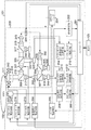
- FIG. 1 is a block diagram showing an embodiment of an optical disk apparatus according to the present invention.
- the optical disc apparatus 101 records or reproduces information by irradiating a laser beam to the optical disc 102 loaded in the apparatus, and communicates with a host 103 such as a PC (Personal Computer) through an interface such as SATA (Serial Advanced Technology Attachment). Do.
- a host 103 such as a PC (Personal Computer) through an interface such as SATA (Serial Advanced Technology Attachment).
- SATA Serial Advanced Technology Attachment
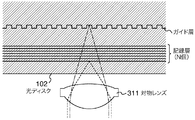
- the structure of the optical disc 102 is illustrated in FIG.
- the optical disc 102 has, for example, a guide layer having a track (guide groove) structure and N recording layers (N ⁇ 1, N is a natural number) having no track structure.
- the optical disc apparatus 101 can generate a laser spot on the recording layer and the guide layer by the objective lens 311.
- the optical disk apparatus 101 includes a controller 201, a signal processing unit 202, an optical pickup 203, a slider motor 204 for moving the optical pickup 203 in the radial direction of the optical disk 102, a slider driving unit 205 for driving the slider motor 204, and light.
- Aberration correction drive means 206 for driving the spherical aberration correction element provided in the pickup 203, a spindle motor 207 for rotating the optical disc 102, and rotation signal generation for generating a signal synchronized with the rotation of the spindle motor 207 Means 208, spindle control means 209 for generating a rotation signal for rotating the spindle motor 207, spindle drive means 210 for driving the spindle motor 207 according to the rotation signal generated by the spindle control means 209,
- a focus error signal is generated which indicates the amount of positional deviation of the laser spot focusing on the recording layer and the recording layer 2 and the positional deviation amount of the laser spot focusing on the guide layer and the guide layer of the optical disc 102
- the optical pickup 203 includes two optical systems having different wavelengths, such as 405 nm and 650 nm. First, the operation at the time of reproduction will be described for the optical system of 405 nm.
- the laser driver 301 is controlled by the controller 201 and outputs a current for driving the laser diode 302. For this drive current, for example, high frequency superposition of several hundreds of MHz is applied to suppress laser noise.
- the laser diode 302 emits laser light having a wavelength of 405 nm with a waveform corresponding to the drive current.
- the emitted laser light is collimated by the collimator lens 303, partially reflected by the beam splitter 304, and condensed onto the power monitor 306 by the condenser lens 305.
- the power monitor 306 feeds back a current or voltage according to the intensity of the laser light to the controller 201.
- the intensity of the laser beam focused on the recording layer of the optical disk 102 is maintained at a desired value, such as 2 mW.
- the laser beam transmitted through the beam splitter 304 is reflected by the polarization beam splitter 307 and transmitted through the dichroic mirror 308.
- the dichroic mirror 308 is an optical element that reflects light of a specific wavelength and transmits light of other wavelengths. Here, light of wavelength 405 nm is transmitted, and light of wavelength 650 nm is reflected.
- the laser beam transmitted through the dichroic mirror 308 is controlled to converge and diverge by the movable lens 309 driven by the aberration correction drive means 206 and becomes circularly polarized light by the 1 ⁇ 4 wavelength plate 310. Focus on the recording layer.
- the objective lens 311 is position controlled by an actuator 312.
- the laser beam reflected by the optical disk 102 has its intensity modulated according to the information recorded on the optical disk 102.
- the light is linearly polarized by the 1 ⁇ 4 wavelength plate 310, passes through the dichroic mirror 308 and the spherical aberration correction element 309, and is transmitted through the polarization beam splitter 307.
- the transmitted laser light is condensed on the detector 314 by the condensing lens 313.
- the detector 314 detects the intensity of the laser light, and outputs a signal corresponding to the intensity to the signal processing unit 202.
- the signal processing unit 202 performs processing such as amplification, equalization, and decoding on the reproduction signal output from the detector 314, and outputs the decoded data to the controller 201.
- the controller 201 outputs data to the host 103.
- the focus error signal generation unit 211 generates a focus error signal for the recording layer from the signal output from the detector 314.
- the focus control unit 212 outputs a focus drive signal corresponding to the focus error signal to the focus drive unit 213 according to a command signal from the controller 201.
- the focus drive unit 213 drives the actuator 312 in the direction perpendicular to the disk surface in response to the focus drive signal. As described above, as the focus control unit 212 and the focus drive unit 213 operate, focus control is performed such that the laser spot irradiated to the recording layer of the optical disc 102 is always focused on the recording layer.
- recording data is input from the host 103 to the controller 201.
- the controller 201 outputs a recording waveform corresponding to the input data to the laser driver 301.
- the laser driver 301 outputs a drive current corresponding to the recording waveform to the laser diode 302, and the laser diode 302 emits a laser beam with a corresponding waveform, thereby performing recording on the recording layer of the optical disc 102.
- the laser driver 301 drives the laser diode 315, and the laser diode 315 emits laser light of wavelength 650 nm.
- a part of the laser light passes through a collimator lens 316, a beam splitter 317, and a condenser lens 318, and the power is monitored by a power monitor 319.
- the intensity of the laser light condensed on the guide layer of the optical disk 102 is held at a desired power, such as 3 mW.
- the laser beam transmitted through the beam splitter 317 is transmitted through the polarization beam splitter 320, and the movable lens 321 controls convergence and divergence.
- the laser beam having passed through the movable lens 321 is reflected by the dichroic mirror 308, passes through the 1 ⁇ 4 wavelength plate 310, and is condensed on the guide layer of the optical disc 102 by the objective lens 311.
- the laser beam reflected by the optical disk 102 is reflected by the polarization beam splitter 320, and is condensed on the detector 323 by the condensing lens 322.
- the tracking error signal generation unit 214 generates a tracking error signal for the guide layer of the optical disc 102 from the signal output from the detector 323.
- the tracking control unit 215 generates a tracking drive signal according to the tracking error signal according to the command signal from the controller 201.
- the tracking drive means 216 drives the actuator 312 in the radial direction of the disk in response to the tracking drive signal. As described above, when the tracking control unit 215 and the tracking drive unit 216 operate, tracking control is performed so that the laser spot irradiated to the guide layer of the optical disk 102 always follows the track on the guide layer.
- the focus error signal generation unit 211 generates a focus error signal which is an error signal in the focus direction with respect to the guide layer of the optical disc 102 from the signal output from the detector 323.
- the focus control unit 212 generates a focus drive signal according to the focus error signal according to a command signal from the controller 201.
- the focus drive unit 213 drives the movable lens 321 according to the focus drive signal. By driving the movable lens 321, control is performed such that the laser spot irradiated to the guide layer of the optical disc 102 is always focused on the guide layer.
- the slider drive unit 205, the aberration correction drive unit 206, and the spindle control unit 209 also operate according to a command signal from the controller 201.
- the same laser driver 301 is used to drive the laser diode 302 and the laser diode 315, a laser driver specific to each laser diode may be provided.
- the focus error signal generation unit 211, the focus control unit 212, and the focus drive unit 213 are shared by the optical system of 405 nm and the optical system of 650 nm, they may be separate configurations.
- FIG. 3 shows the process flow of the optical disc apparatus 101 when the optical disc 102 is inserted into the optical disc apparatus 101.
- the optical disc apparatus 101 confirms the presence / absence of the disc and the disc type in S402. At this time, for example, the optical disc apparatus 101 can irradiate the optical disc 102 with laser light and perform recognition by reflected light.
- step S403 adjustment processing for optimizing various parameters in the optical disc apparatus 101 is performed on the inserted optical disc 102.
- the various parameters include, for example, adjusting the amplification factor of an amplifier included in the focus control unit 212 or the tracking control unit 215 in accordance with the reflectance of the optical disk 102.
- the management information of the optical disc 102 is read out in S404.
- step S405 recording or reproduction is possible, and recording or reproduction can be performed according to a command from the host 103.
- the timing of the adjustment process S403 is not limited to this, and part of the adjustment process may be performed after the management information read S404 or the like.
- One of the features of this embodiment is the working distance WD1 of the objective lens when recording or reproducing the first recording layer, as shown in FIG. 4, and a recording layer different from the first recording layer (for convenience, 2) is characterized in that the working distance WD2 of the objective lens when recording or reproducing is substantially equal.
- This feature makes it possible to rationalize the optical disc apparatus.
- detailed description will be made in order.
- the recording layer and the guide layer are not separated. Therefore, in the case of such a conventional optical disc, the problem to be solved by the present invention does not occur.
- an optical disk apparatus corresponding to an optical disk having a plurality of recording layers, it is necessary to correct a change in spherical aberration generated according to a change in substrate thickness.
- the degree of convergence and divergence of the light beam incident on the objective lens is adjusted with respect to the light beam to be focused on the recording layer, and the object side distance of the objective lens is changed to cancel the spherical aberration.
- the spherical aberration is intentionally generated and corrected. Therefore, the optical system is provided with a lens different from the objective lens, and means for changing the object side distance of the objective lens by moving the lens in the direction of the optical axis is generally used.
- reference numeral 309 in FIG. 1 corresponds to the lens.
- the focus for adjusting the light beam to be focused on the guide layer is adjusted.
- It has a lens.
- reference numeral 321 in FIG. 1 corresponds to the lens.
- the degree of convergence and divergence of the light beam incident on the objective lens is changed by the lens of reference numeral 321, and the focus of the light beam to be focused on the guide layer is adjusted. Since the lens 309 and the lens 321 move in the optical axis direction, they are called movable lenses in the present embodiment for the sake of convenience.
- FIG. 5 is a view focusing on an optical component in the optical disk apparatus shown in FIG.
- reference numerals 309a and 321a indicate the position of the movable lens when recording or reproducing in a predetermined recording layer (first recording layer), and reference numerals 309 and 321 indicate the positions of the predetermined recording layer.
- the position of the movable lens when recording or reproducing in another layer (second recording layer) having a different substrate thickness is shown.
- the movable directions of the movable lens 309 and the movable lens 321 are shown in one direction, but the present embodiment is not limited to this, and the first recording layer and the second recording layer The movable direction changes depending on the positional relationship.
- the working distance WD1 of the objective lens when recording or reproducing the first recording layer and the working distance WD2 of the objective lens when recording or reproducing the second recording layer are substantially equal. It is characterized by Therefore, focusing on the light beam focused on the guide layer, the degree of convergence and divergence of the light beam incident on the objective lens during recording or reproduction of the first recording layer and recording or reproduction of the second recording layer is It will be almost the same.
- the position of the movable lens when recording or reproducing on the first recording layer and the movable lens when recording or reproducing on the second recording layer Let ⁇ d1 and ⁇ d2 be the difference between the positions of
- the first recording layer may be any layer among the recording layers of the optical disc 102. That is, in the present embodiment, when recording or reproducing a recording layer having a different substrate thickness, the movable lens 321 is used if the position of the movable lens when recording or reproducing another layer is made before that as the reference.
- the driving amount of the movable lens 309 is larger than that.
- the movable directions of the movable lens 309 and the movable lens 321 are shown in one direction, but the present invention is not limited to this, and the first recording layer and the second recording layer
- the movable direction may be changed depending on the positional relationship of the recording layer.
- One essence of this embodiment is that the positional differences ⁇ d1 and ⁇ d2 satisfy (Equation 4).
- the drive amount of the movable lens 321 can be reduced, the drive range of the drive mechanism for driving the movable lens can be designed to be small, which is effective in downsizing the apparatus. In addition, since the drive amount is small, there is an effect in saving electricity of the optical disk apparatus.
- the present embodiment is also effective from the viewpoint of the amount of spherical aberration of the light beam focused on the guide layer.
- spherical aberration occurs accordingly.
- the degree of convergence and divergence of the light beam incident on the objective lens changes, spherical aberration occurs accordingly.
- the degree of convergence and divergence of the light beam focused on the guide layer with respect to the objective lens is substantially unchanged, so there is almost no change in spherical aberration. It is. If the degree of convergence / divergence to the objective lens changes significantly, spherical aberration occurs, which may deteriorate the focusing characteristics of the light beam.
- the working distances substantially equal to the first recording layer and the second recording layer for example, it can be realized by using an objective lens having the following characteristics.
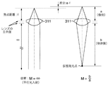
- FIG. 6 shows that the light beam is incident on the objective lens 311 at a magnification of M.
- the image point position changes according to the lens formula shown in (Equation 5).
- a is the image side distance
- b is the object side distance
- f is the focal length of the objective lens.
- a spherical aberration corresponding to the substrate thickness ⁇ is newly generated, so that, for example, at a magnification M satisfying (Equation 2), a spherical aberration in the opposite direction substantially equivalent to the spherical aberration is generated in the objective lens. If so, the spherical aberration corresponding to the substrate thickness ⁇ can be corrected.
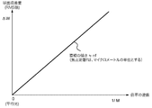
- the numerical aperture of the objective lens is 0.85, assuming that the wavelength is ⁇ , the RMS value (Root Mean Square) of the spherical aberration amount corresponding to a substrate thickness of 10 micrometers is approximately 0.1 ⁇ . Therefore, as shown in FIG.
- the working distance with respect to the first recording layer and the second recording layer is approximately It can be made equal.
- the unit of the focal length f is in micrometers.
- the light beam condensed on the guide layer is incident on the objective lens as substantially parallel light. Even when the position of the objective lens in the direction of the optical axis changes due to surface deflection of the optical disc 102 by substantially collimated light incidence, the movable lens 321 is substantially driven without substantially changing the degree of convergence / divergence to the objective lens. Can be focused on the guide layer.
Landscapes
- Physics & Mathematics (AREA)
- Optics & Photonics (AREA)
- Optical Head (AREA)
- Optical Recording Or Reproduction (AREA)
- Optical Record Carriers And Manufacture Thereof (AREA)
Abstract
溝構造を持つガイド層と複数の記録層が積層された多層ディスクにおいて、ガイド層に集光する光ビームの収束・発散具合が対物レンズに対して変化すると、球面収差が発生する。これにより、ガイド層に集光する光ビームの集光性能が劣化する恐れがある。 各記録層に対して、対物レンズの作動距離を略等しくする。実現する手段としては、例えば対物レンズのI/O特性を最適化する。
Description
本出願は、2011年4月22日に出願された日本特許出願第2011-095668号の優先権を主張し、その内容を参照することにより本出願に取り込む。
本発明は、レーザを用いて光ディスクから情報を再生、または光ディスクに情報を記録する光ディスク装置、および該光ディスク装置に搭載する対物レンズに関する。
近年、Blu-ray Disc(TM)規格の光ディスクにおいて、記録容量を増加させるために3層や4層の記録層を有する光ディスクが開発され、規格化が行われた。今後更なる大容量化を目的として、より多数の記録層を有する光ディスクの開発が行われると予想されている。たとえば特許文献1および非特許文献1では、トラッキングサーボ制御を行うための物理的な溝構造を持つ層(以下、ガイド層)をもうけ、記録再生を行う層(記録層)にはランド/グルーブ構造を有さない光ディスク(グルーブレスディスク)が示されており、記録層を多数積層する場合でも製造が容易であるとされている。
M.Ogasawara et.al.、"16 Layers Write Once Disc with a Separated Guide Layer"、ISOM2010、Th-L-07
上記のようなグルーブレスディスクを記録再生する際の課題のひとつとして、対物レンズによって第1の光ビームを記録層に集光させると同時に、同一の対物レンズを用いて第2の光ビームをガイド層に集光させる必要がある。
ここで、再生および記録時において、対物レンズとディスク表面の間隔として定義される作動距離が記録層毎に異なると、ガイド層の位置は固定のため、ガイド層に集光させる光ビームの収束・発散具合を対物レンズに対して記録層毎に異なるように設定することになる。
対物レンズに入射する光ビームの収束・発散具合が変わると、それに伴って球面収差が発生するため、ガイド層に集光する光ビームの集光性能が劣化、または該球面収差を補正するための素子が新たに必要になる等の課題が生じる。ガイド層に集光する光ビームに対して、新たに球面収差補正素子を追加するのは、光ディスク装置の価格、大きさ、複雑さの観点から不利となる。
そこで本発明の目的は、装置の合理化やガイド層に集光する光ビームの集光性能を確保する光ディスク装置を提供することである。
上記課題は特許請求の範囲に記載の発明により解決される。
本発明によれば、装置の合理化やガイド層に集光する光ビームの集光性能が向上する。
本発明の他の目的、特徴及び利点は添付図面に関する以下の本発明の実施例の記載から明らかになるであろう。
本発明の他の目的、特徴及び利点は添付図面に関する以下の本発明の実施例の記載から明らかになるであろう。
以下、本発明の実施の形態を図面に基づいて説明する。
図1は、本発明に従う光ディスク装置の一実施例を示すブロック構成図である。光ディスク装置101は装置に装着された光ディスク102にレーザ光を照射することで情報の記録または再生を行い、SATA(Serial Advanced Technology Attachment)などのインターフェースを通じてPC(Personal Computer)などのホスト103と通信を行う。
光ディスク102の構造を図2に例示する。光ディスク102は例えばトラック(ガイド溝)の構造を持つガイド層と、トラックの構造を持たないN個の記録層(N≧1、Nは自然数)を有する。光ディスク装置101は対物レンズ311によって、記録層とガイド層にレーザスポットを生じることができる。
本光ディスク装置101は、コントローラ201と信号処理部202と、光ピックアップ203と、光ピックアップ203を光ディスク102の半径方向に移動するスライダモータ204と、スライダモータ204を駆動するスライダ駆動手段205と、光ピックアップ203中に備えられた球面収差補正素子を駆動するための収差補正駆動手段206と、光ディスク102を回転するためのスピンドルモータ207と、スピンドルモータ207の回転に同期した信号を生成する回転信号生成手段208と、スピンドルモータ207を回転させるための回転信号を生成するスピンドル制御手段209と、スピンドル制御手段209が生成する回転信号に応じてスピンドルモータ207を駆動するスピンドル駆動手段210と、光ディスク102の記録層と記録層に対して合焦するレーザスポットの位置ずれ量、ならびに光ディスク102のガイド層とガイド層に対して合焦するレーザスポットの位置ずれ量を示すフォーカス誤差信号を生成するフォーカス誤差信号生成手段211と、フォーカス誤差信号に応じてフォーカス駆動信号を生成するフォーカス制御手段212と、フォーカス駆動信号に応じて光ピックアップ203中に備えられたアクチュエータ312、ならびに可動レンズ321を駆動するフォーカス駆動手段213と、光ディスク102のガイド層上のトラックとレーザスポットとの位置ずれ量を示すトラッキング誤差信号を生成するトラッキング誤差信号生成手段214と、トラッキング誤差信号に応じてトラッキング駆動信号を生成するトラッキング制御手段215と、トラッキング駆動信号に応じてアクチュエータ312を駆動するトラッキング駆動手段216とを備えている。
光ピックアップ203は、たとえば405nmと650nmなど波長の異なる2つの光学系を備えている。まず、405nmの光学系について再生時の動作を説明する。レーザドライバ301は、コントローラ201によって制御されており、レーザダイオード302を駆動する電流を出力する。この駆動電流は、例えばレーザノイズを抑制するために数百MHzの高周波重畳が印加されている。レーザダイオード302は、駆動電流に応じた波形で波長405nmのレーザ光を出射する。出射されたレーザ光はコリメータレンズ303にて平行光となり、ビームスプリッタ304で一部が反射し、集光レンズ305によってパワーモニタ306に集光する。パワーモニタ306は、レーザ光の強度に応じた電流または電圧をコントローラ201にフィードバックする。これによって光ディスク102の記録層に集光するレーザ光の強度が、たとえば2mWなど所望の値に保持される。一方、ビームスプリッタ304を透過したレーザ光は偏光ビームスプリッタ307にて反射し、ダイクロイックミラー308を透過する。ダイクロイックミラー308は特定の波長の光を反射し、その他の波長の光を透過する光学素子である。ここでは波長405nmの光を透過し、650nmの光を反射するものとする。ダイクロイックミラー308を透過したレーザ光は、収差補正駆動手段206にて駆動される可動レンズ309によって収束・発散が制御され、1/4波長板310にて円偏光となり、対物レンズ311によって光ディスク102の記録層に集光する。対物レンズ311は、アクチュエータ312によって位置制御される。光ディスク102によって反射したレーザ光は、光ディスク102に記録された情報に応じて強度が変調される。1/4波長板310にて直線偏光となり、ダイクロイックミラー308および球面収差補正素子309を経て、偏光ビームスプリッタ307を透過する。透過したレーザ光は、集光レンズ313によってディテクタ314に集光する。ディテクタ314はレーザ光の強度を検出し、これに応じた信号を信号処理部202に出力する。信号処理部202は、ディテクタ314から出力された再生信号に対し増幅、等化、復号などの処理を行い、復号したデータをコントローラ201に出力する。コントローラ201はデータをホスト103に出力する。
またフォーカス誤差信号生成手段211は、ディテクタ314から出力された信号から、記録層に対するフォーカス誤差信号を生成する。フォーカス制御手段212はコントローラ201からの指令信号により、フォーカス誤差信号に対応したフォーカス駆動信号をフォーカス駆動手段213に出力する。フォーカス駆動手段213はフォーカス駆動信号に応じて、アクチュエータ312をディスク面に垂直な方向に駆動する。上述したようにフォーカス制御手段212とフォーカス駆動手段213が動作することで、光ディスク102の記録層に照射されたレーザスポットが常に記録層で合焦するようにフォーカス制御が行われる。
記録を行う際には、ホスト103からコントローラ201へと記録データが入力される。コントローラ201は、入力されたデータに対応した記録波形をレーザドライバ301へ出力する。レーザドライバ301は、記録波形に応じた駆動電流をレーザダイオード302に出力し、レーザダイオード302が対応した波形でレーザ光を出射することで光ディスク102の記録層に記録が行われる。
次に、650nmの光学系について説明する。本光学系については、記録時と再生時での動作の差異はない。405nmの光学系と同様に、レーザドライバ301がレーザダイオード315を駆動し、レーザダイオード315は波長650nmのレーザ光を出射する。レーザ光の一部は、コリメータレンズ316、ビームスプリッタ317、集光レンズ318を経て、パワーモニタ319にてパワーがモニタされる。モニタしたパワーをコントローラ201にフィードバックすることで、光ディスク102のガイド層に集光するレーザ光の強度が、たとえば3mWなど所望のパワーに保持される。ビームスプリッタ317を透過したレーザ光は、偏光ビームスプリッタ320を透過し、可動レンズ321にて収束・発散の制御が行われる。可動レンズ321を経たレーザ光は、ダイクロイックミラー308にて反射し、1/4波長板310を経て、対物レンズ311により光ディスク102のガイド層に集光する。光ディスク102にて反射したレーザ光を偏光ビームスプリッタ320にて反射し、集光レンズ322にてディテクタ323に集光する。
トラッキング誤差信号生成手段214は、ディテクタ323から出力された信号から、光ディスク102のガイド層に対するトラッキング誤差信号を生成する。トラッキング制御手段215はコントローラ201からの指令信号により、トラッキング誤差信号に応じたトラッキング駆動信号を生成する。トラッキング駆動手段216はトラッキング駆動信号に応じてアクチュエータ312をディスクの半径方向に駆動する。上述したようにトラッキング制御手段215とトラッキング駆動手段216が動作することで、光ディスク102のガイド層に照射されたレーザスポットが常にガイド層上のトラックを追従するようにトラッキング制御が行われる。
また、フォーカス誤差信号生成手段211は、ディテクタ323から出力された信号から、光ディスク102のガイド層に対するフォーカス方向の誤差信号であるフォーカス誤差信号を生成する。フォーカス制御手段212はコントローラ201からの指令信号により、フォーカス誤差信号に応じたフォーカス駆動信号を生成する。フォーカス駆動手段213はフォーカス駆動信号に応じて可動レンズ321を駆動する。可動レンズ321を駆動することで、光ディスク102のガイド層に照射されたレーザスポットが常にガイド層で合焦するように制御が行われる。
またスライダ駆動手段205、収差補正駆動手段206、スピンドル制御手段209に関しても、コントローラ201からの指令信号により動作する。
なお、ここではレーザダイオード302とレーザダイオード315を駆動するために同一のレーザドライバ301を用いたが、それぞれのレーザダイオードに固有のレーザドライバを備えても良い。またフォーカス誤差信号生成手段211、フォーカス制御手段212およびフォーカス駆動手段213も405nmの光学系と650nmの光学系で共有する構成としたが、別々の構成であっても良い。
図3に光ディスク装置101に光ディスク102を挿入時の光ディスク装置101の処理フローを示した。
S401で光ディスク102を光ディスク装置101に挿入すると、S402で光ディスク装置101はディスクの有無の確認やディスク種別の確認を行う。このとき、たとえば光ディスク装置101は光ディスク102にレーザ光を照射して、反射光によって認識を行うことができる。
次にS403では、挿入された光ディスク102に対して、光ディスク装置101内の各種パラメータを好適するための調整処理を行う。各種パラメータとは、たとえばフォーカス制御手段212やトラッキング制御手段215内に含まれる増幅器の増幅率を光ディスク102の反射率にあわせて調節することなどが挙げられる。
各種調整を行った後、S404で光ディスク102の管理情報を読み出す。
S405まで処理が進むと、記録または再生可能な状態となり、ホスト103からのコマンドに応じて記録または再生を行うことができる。
調整処理S403のタイミングはこれに限るものではなく、一部の調整処理を管理情報読み出しS404の後などに行ってもよい。
続いて、本実施例の特徴となる点について説明する。本実施例の特徴の一つは図4に示すように、第1の記録層を記録または再生する際の対物レンズの作動距離WD1と、第1の記録層とは異なる記録層(便宜上、第2の記録層と呼ぶ)を記録または再生する際の対物レンズの作動距離WD2が略等しい事を特徴としている。この特徴により光ディスク装置の合理化ができる。以下、順を追って詳細に説明する。
なお、記録層にグルーブ構造を有する光ディスクである従来のBD多層などは、記録層とガイド層が分離していない。そのため、このような従来の光ディスクの場合は、本発明が解決しようとする課題は生じない。
複数の記録層を備えた光ディスクに対応する光ディスク装置は、基板厚の変化に応じて発生する球面収差の変化を補正する必要がある。一般には、記録層に合焦させる光ビームに対し、対物レンズに入射する該光ビームの収束・発散具合を調整し、該対物レンズの物体側距離を変化させる事で該球面収差を打ち消すための球面収差を故意に発生させ、補正する。そのため、光学系には対物レンズとは異なるレンズを備え、該レンズを光軸方向に動かす事で対物レンズの物体側距離を変える手段が一般的に用いられる。本実施例では図1における符号309が該レンズに相当する。また該光ディスク装置においては、記録層に合焦させる光ビームとは異なる光ビームを光ディスク102のガイド層に合焦させる必要があるため、ガイド層に合焦させる光ビームのフォーカスを調整するためのレンズを備える。本実施例では図1における符号321が該レンズに相当する。具体的には、符号321のレンズによって対物レンズに入射する光ビームの収束・発散具合が変わり、ガイド層に合焦させる光ビームのフォーカスを調整する。レンズ309およびレンズ321は光軸方向に動く事から、本実施例では便宜上、可動レンズと呼ぶ事とする。
図5は、図1に示した光ディスク装置において、光学部品に着目した図である。図5において符号309aと符号321aは所定の記録層(第1の記録層)に記録または再生している時の可動レンズの位置を示しており、符号309および符号321は該所定の記録層に対して基板厚さが異なる別の層(第2の記録層)に記録または再生している時の可動レンズの位置を示している。ここで、記録および再生中に可動レンズが停止せず連続的に動く場合は、平均的な位置を表しているものとする。なお、図5において、可動レンズ309および可動レンズ321の可動方向を一方向で示しているが、本実施例はこれに限定されるものではなく、第1の記録層と第2の記録層の位置関係によって可動方向は変わる。
本実施例では前述したとおり、第1の記録層を記録または再生する際の対物レンズの作動距離WD1と、第2の記録層を記録または再生する際の対物レンズの作動距離WD2が略等しい事を特徴としている。そのため、ガイド層に集光する光ビームに着目すると、第1の記録層を記録または再生時および第2の記録層を記録または再生時において、対物レンズに入射する光ビームの収束・発散具合はほぼ変わらない事となる。
対物レンズに入射する光ビームの収束・発散具合がほぼ変わらないということは、可動レンズ321の駆動量が非常に小さい事を意味する。なお作動距離が完全に等しければ、理想的にはΔd2=0となる。一方、記録層に照射させる光ビームに関しては、ディスク表面から集光点までの基板厚が変わるため、基板厚の違いで生じる球面収差を補正するため、光ビームの対物レンズに対する収束・発散具合を変化させる必要が生じ、可動レンズ(309)を動かす必要がある。換言すれば、より具体的には、本実施例は、第1の記録層に記録または再生している時の可動レンズの位置と第2の記録層に記録または再生している時の可動レンズの位置の差分を図5に示すようにΔd1およびΔd2とすると、
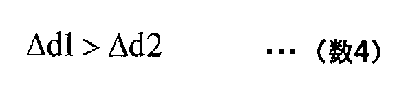
を満たせばよい。なお、作動距離WD1とWD2が完全に等しくない場合であっても、(数4)や(数4)を別表現した(数1)を満たすことにより、作動距離WD1とWD2の差を小さくすることが可能となり、ガイド層に集光する光ビームの集光性能を確保できる。
なお上記において、第1の記録層は光ディスク102の記録層のうち、どの層でも良い。つまり本実施例は、基板厚が異なる記録層を記録または再生する際は、それよりも前に別の層を記録または再生していた時の可動レンズ位置を基準にした場合、可動レンズ321に比べて可動レンズ309の駆動量が大きい事を一つの特徴としている。なお前述したように、図5において、可動レンズ309および可動レンズ321の可動方向を一方向で示しているが、本発明はこれに限定されるものではなく、第1の記録層と第2の記録層の位置関係によって可動方向は変わっても良い。本実施例の一つの本質は、位置の差分Δd1およびΔd2が(数4)を満足する事である。
本実施例では、可動レンズ321の駆動量を小さくできるので、可動レンズを駆動する駆動機構の駆動範囲を小さく設計でき、装置の小型化に効果がある。また駆動量が小さいため、光ディスク装置の省電化に効果がある。
さらに本実施例では、ガイド層に集光する光ビームの球面収差量の観点からも効果がある。一般に、対物レンズに入射する光ビームの収束・発散具合が変わると、それに応じて球面収差が発生する。しかしながら本実施例では第1および第2の記録層を記録または再生時において、ガイド層に集光する光ビームの対物レンズに対する収束・発散具合がほぼ変わらないため、球面収差の変化がほとんど無いためである。対物レンズに対する収束・発散具合が大きく変化すると球面収差が発生するため、光ビームの集光特性が劣化する恐れがある。その観点で、本実施例のように第1の記録層と第2の記録層における作動距離を略等しくすることは、球面収差の観点で効果は大きい。どの記録層を記録または再生する場合でも、所定の位置にあるガイド層に光ビームを合焦させる事が必要なため、本実施例を適用する事で、上記の効果が期待できる。
第1の記録層および第2の記録層に対して作動距離を略等しくするためには、例えば以下に示す様な特性の対物レンズを用いることでも実現できる。
図6は、対物レンズ311に倍率Mで光ビームが入射している様子を示したものである。倍率Mの値が変わると(数5)に示すレンズの公式に従って像点位置が変化する。

ここでaは像側距離、bは物体側距離、fは対物レンズの焦点距離である。なお、倍率Mが無限大、いわゆる平行光入射の状態と、倍率M=b/aの場合における像点位置の差分a-fは(数5)を用いて(数6)のように表す事ができる。

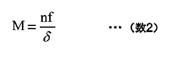
つまり、対物レンズに平行光を入射した際に光ディスク102内にて集光する光ビームの球面収差量が最小となる基板厚からδだけ異なる厚さに位置する記録層を記録または再生する際は、基板の屈折率をnとすると、空気換算距離であるδ/nが(数6)と等しければ、つまり(数2)が成り立てば、記録または再生する記録層の位置によらず対物レンズの作動距離は同じとなる。もちろん、厳密に(数2)、(数6)を満たす必要はなく、誤差を含めた範囲でこれらを満たせばよい。
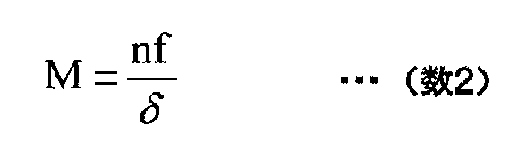
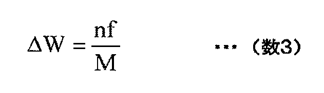
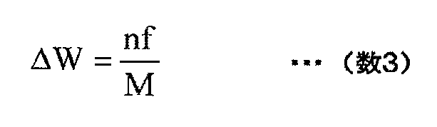
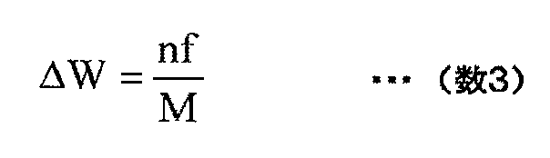
この際、基板厚δに相当する球面収差が新たに発生するので、例えば(数2)を満足する倍率Mにて、該球面収差量と略同等の逆向きの球面収差が対物レンズにて発生すれば、基板厚δに相当する球面収差を補正できる。例えば対物レンズの開口数が0.85の時、波長をλとすると、基板厚10マイクロメートルに相当する球面収差量のRMS値(Root Mean Square)は、略0.1λである。よって図7に示すように、対物レンズに平行光を入射した際に対物レンズにて発生する球面収差量のRMS値に対して、対物レンズの倍率がMの場合に発生する球面収差量のRMS値との差分を入射光の波長で規格化した値ΔWが(数3)を満足するような対物レンズを用いる事で、第1の記録層および第2の記録層に対して作動距離を略等しくする事ができる。なお(数3)において焦点距離fの単位は、マイクロメートルとする。
また、ガイド層に集光する光ビームは、対物レンズに対して略平行光で入射することを特徴の一つとしている。略平行光で入射することで、光ディスク102の面振れによって対物レンズの光軸方向位置が変化しても、対物レンズに対する収束・発散具合をほぼ変えることなく、つまり可動レンズ321をほぼ駆動することなく、ガイド層に合焦させる事ができる。
もちろん、厳密に(数3)を満たす必要はなく、誤差を含めた範囲でこれを満たせばよい。
上記記載は実施例についてなされたが、本発明はそれに限らず、本発明の精神と添付の請求の範囲の範囲内で種々の変更および修正をすることができることは当業者に明らかである。
上記記載は実施例についてなされたが、本発明はそれに限らず、本発明の精神と添付の請求の範囲の範囲内で種々の変更および修正をすることができることは当業者に明らかである。
101 光ディスク装置
102 光ディスク
103 ホスト
201 コントローラ
202 信号処理部
203 光ピックアップ
204 スライダモータ
205 スライダ駆動手段
206 収差補正駆動手段
207 スピンドルモータ
208 回転信号生成手段
209 スピンドル制御手段
210 スピンドル駆動手段
211 フォーカス誤差信号生成手段
212 フォーカス制御手段
213 フォーカス駆動手段
214 トラッキング誤差信号生成手段
215 トラッキング制御手段
216 トラッキング駆動手段
217 レンズ
218 レンズ
301 レーザドライバ
302 レーザダイオード
303 コリメータレンズ
304 ビームスプリッタ
305 レンズ
306 パワーモニタ
307 偏光ビームスプリッタ
308 ダイクロイックミラー
309 可動レンズ
310 1/4波長板
311 対物レンズ
312 アクチュエータ
313 レンズ
314 ディテクタ
315 レーザダイオード
316 コリメータレンズ
317 ビームスプリッタ
318 レンズ
319 パワーモニタ
320 偏光ビームスプリッタ
321 可動レンズ
322 レンズ
323 ディテクタ
102 光ディスク
103 ホスト
201 コントローラ
202 信号処理部
203 光ピックアップ
204 スライダモータ
205 スライダ駆動手段
206 収差補正駆動手段
207 スピンドルモータ
208 回転信号生成手段
209 スピンドル制御手段
210 スピンドル駆動手段
211 フォーカス誤差信号生成手段
212 フォーカス制御手段
213 フォーカス駆動手段
214 トラッキング誤差信号生成手段
215 トラッキング制御手段
216 トラッキング駆動手段
217 レンズ
218 レンズ
301 レーザドライバ
302 レーザダイオード
303 コリメータレンズ
304 ビームスプリッタ
305 レンズ
306 パワーモニタ
307 偏光ビームスプリッタ
308 ダイクロイックミラー
309 可動レンズ
310 1/4波長板
311 対物レンズ
312 アクチュエータ
313 レンズ
314 ディテクタ
315 レーザダイオード
316 コリメータレンズ
317 ビームスプリッタ
318 レンズ
319 パワーモニタ
320 偏光ビームスプリッタ
321 可動レンズ
322 レンズ
323 ディテクタ
Claims (7)
- 第1の光源と第2の光源と、
前記第1の光源を出射した第1の光ビームおよび前記第2の光源を出射した第2の光ビームを光ディスクに集光する対物レンズと、
前記対物レンズに入射する前記第1の光ビームの収束・発散の制御を行う第1の可動レンズと、
前記対物レンズに入射する前記第2の光ビームの収束・発散の制御を行う第2の可動レンズと、を備えた光ディスク装置において、
前記光ディスクはトラッキング制御を行うためのガイド層と複数の記録層を備えており、
前記第1の光ビームは前記記録層に集光し、
前記第2の光ビームは前記ガイド層に集光し、
前記光ディスクの第1の記録層を記録または再生している時の前記対物レンズの作動距離と、前記光ディスクの第2の記録層を記録または再生している時の前記対物レンズの作動距離が略等しい事を特徴とする光ディスク装置。 - 請求項1記載の光ディスク装置において、
前記第1の記録層を記録または再生している時の前記第1の可動レンズの光軸方向の位置をA1、
前記第1の記録層を記録または再生している時の前記第2の可動レンズの光軸方向の位置をB1、
前記第2の記録層を記録または再生している時の前記第1の可動レンズの光軸方向の位置をA2、
前記第2の記録層を記録または再生している時の前記第2の可動レンズの光軸方向の位置をB2、とした場合、

を満足する事を特徴とする光ディスク装置。 - 請求項1記載の光ディスク装置において、前記第2の光ビームは、前記対物レンズに対して略平行光で入射する事を特徴とする光ディスク装置。
- 請求項1記載の光ディスク装置において、
前記第1の光ビームが平行光で前記対物レンズに入射した際に前記第1の光ビームの球面収差量が最小となる基板厚さに対してδ異なる厚さに位置する記録層を記録または再生する際は、前記対物レンズの焦点距離をf、前記光ディスクの基板の屈折率をnとした場合、前記対物レンズの倍率Mが概ね数2を満足するように前記第1の光ビームを前記対物レンズに入射する事を特徴とする光ディスク装置。
- 対物レンズに平行光を入射した際に発生する球面収差量のRMS値に対して前記対物レンズの倍率がMの場合に発生する球面収差量のRMS値との差分を該入射光の波長で規格化した値ΔWは、前記対物レンズの焦点距離をマイクロメートルの単位で表した際の焦点距離をf、前記対物レンズが対応する光ディスクの基板の屈折率をnとした場合、概ね数3を満足する対物レンズ。
- 請求項1に記載の光ディスク装置であって、
前記対物レンズは、当該対物レンズに平行光を入射した際に発生する球面収差量のRMS値に対して前記対物レンズの倍率がMの場合に発生する球面収差量のRMS値との差分を該入射光の波長で規格化した値ΔWは、前記対物レンズの焦点距離をマイクロメートルの単位で表した際の焦点距離をf、前記対物レンズが対応する光ディスクの基板の屈折率をnとした場合、概ね数3を満足する対物レンズであることを特徴とする光ディスク装置。
- 第1の光ビームを出射する第1の光源と前記第1の光ビームの波長よりも長い波長の第2の光ビームを出射する第2の光源を有する光ディスク装置であって、
前記第1の光源を出射した第1の光ビームおよび前記第2の光源を出射した第2の光ビームを光ディスクに集光する対物レンズと、
前記対物レンズに入射する前記第1の光ビームの収束・発散の制御を行う第1の可動レンズと、
前記対物レンズに入射する前記第2の光ビームの収束・発散の制御を行う第2の可動レンズと、を備え、
前記光ディスクは、トラッキング制御を行うためのガイド層と、複数の記録層を備えており、
前記第1の光ビームは前記記録層に集光され、
前記第2の光ビームは前記ガイド層に集光され、
前記第1の記録層を記録または再生している時の前記第1の可動レンズの光軸方向の位置をA1、
前記第1の記録層を記録または再生している時の前記第2の可動レンズの光軸方向の位置をB1、
前記第2の記録層を記録または再生している時の前記第1の可動レンズの光軸方向の位置をA2、
前記第2の記録層を記録または再生している時の前記第2の可動レンズの光軸方向の位置をB2、とした場合、

を満足する事を特徴とする光ディスク装置。
Applications Claiming Priority (2)
| Application Number | Priority Date | Filing Date | Title |
|---|---|---|---|
| JP2011095668A JP2012226813A (ja) | 2011-04-22 | 2011-04-22 | 対物レンズ、およびそれを搭載した光ディスク装置 |
| JP2011-095668 | 2011-04-22 |
Publications (1)
| Publication Number | Publication Date |
|---|---|
| WO2012144343A1 true WO2012144343A1 (ja) | 2012-10-26 |
Family
ID=47041455
Family Applications (1)
| Application Number | Title | Priority Date | Filing Date |
|---|---|---|---|
| PCT/JP2012/059454 Ceased WO2012144343A1 (ja) | 2011-04-22 | 2012-04-06 | 対物レンズ、およびそれを搭載した光ディスク装置 |
Country Status (2)
| Country | Link |
|---|---|
| JP (1) | JP2012226813A (ja) |
| WO (1) | WO2012144343A1 (ja) |
Citations (3)
| Publication number | Priority date | Publication date | Assignee | Title |
|---|---|---|---|---|
| JP2001307344A (ja) * | 2000-04-19 | 2001-11-02 | Olympus Optical Co Ltd | 情報記録再生装置 |
| JP2009004073A (ja) * | 2007-05-18 | 2009-01-08 | Konica Minolta Opto Inc | 光ピックアップ装置 |
| JP2011076686A (ja) * | 2009-10-01 | 2011-04-14 | Sony Corp | 記録装置、記録方法、光記録媒体 |
Family Cites Families (4)
| Publication number | Priority date | Publication date | Assignee | Title |
|---|---|---|---|---|
| JP2009187633A (ja) * | 2008-02-07 | 2009-08-20 | Sony Corp | 光ディスク装置及び光ビーム照射角度調整方法 |
| JP5116878B2 (ja) * | 2009-07-10 | 2013-01-09 | パイオニア株式会社 | ガイド層分離型の光ディスク、光ディスクドライブ装置及びトラッキング制御方法 |
| JP5621227B2 (ja) * | 2009-08-26 | 2014-11-12 | ソニー株式会社 | 光情報装置及び光ピックアップ |
| JP2011086327A (ja) * | 2009-10-14 | 2011-04-28 | Sony Corp | 光記録媒体、光記録媒体の製造方法 |
-
2011
- 2011-04-22 JP JP2011095668A patent/JP2012226813A/ja active Pending
-
2012
- 2012-04-06 WO PCT/JP2012/059454 patent/WO2012144343A1/ja not_active Ceased
Patent Citations (3)
| Publication number | Priority date | Publication date | Assignee | Title |
|---|---|---|---|---|
| JP2001307344A (ja) * | 2000-04-19 | 2001-11-02 | Olympus Optical Co Ltd | 情報記録再生装置 |
| JP2009004073A (ja) * | 2007-05-18 | 2009-01-08 | Konica Minolta Opto Inc | 光ピックアップ装置 |
| JP2011076686A (ja) * | 2009-10-01 | 2011-04-14 | Sony Corp | 記録装置、記録方法、光記録媒体 |
Also Published As
| Publication number | Publication date |
|---|---|
| JP2012226813A (ja) | 2012-11-15 |
Similar Documents
| Publication | Publication Date | Title |
|---|---|---|
| JP2000131603A (ja) | 光学ヘッド及び記録再生装置 | |
| US8014258B2 (en) | Optical pickup having radially arranged lenses in a low profile construction | |
| JP2008204517A (ja) | 光ヘッドおよび光学的情報記録再生装置 | |
| EP2202544A1 (en) | Aspheric lens and optical pickup including the same | |
| US20080205249A1 (en) | Compatible optical pickup and optical information storage medium system employing- the same | |
| US20090274020A1 (en) | Optical head unit and optical information recording/reproducing apparatus | |
| JPWO2008149522A1 (ja) | 光学ヘッド装置、及び記録及び/又は再生装置 | |
| JP4472563B2 (ja) | 光学ユニットおよび光ピックアップならびに光情報処理装置 | |
| US8064316B2 (en) | Optical system, optical pickup apparatus, and optical disc apparatus for extracting signal beams | |
| WO2012144343A1 (ja) | 対物レンズ、およびそれを搭載した光ディスク装置 | |
| JP2006164493A (ja) | 光学ヘッド及び情報記録再生装置 | |
| US8526286B2 (en) | Optical pick-up apparatus with diffractive optical element and optical recording/reproducing apparatus having the same | |
| US20070291601A1 (en) | Method of correcting chromatic aberration generated during conversion from reproducing mode to recording mode, and recording method and recording and reproducing apparatus adopting the correction method | |
| JP4312214B2 (ja) | 光ピックアップ装置 | |
| CN102087866A (zh) | 拾取装置、光记录再生装置及记录再生方法 | |
| JP2009537054A (ja) | 光学走査デバイス | |
| JPWO2007069612A1 (ja) | 光ヘッドおよび光情報装置 | |
| US8614936B2 (en) | Pickup head, information recording method and reproducing method | |
| JP4329566B2 (ja) | 収差補償装置及び収差補償方法 | |
| JP6288233B2 (ja) | 光ピックアップ装置および光ディスク装置 | |
| JP4254850B2 (ja) | 収差補正装置 | |
| JP6064760B2 (ja) | 光ピックアップ装置および光ディスク装置 | |
| WO2013038457A1 (ja) | 光ディスクおよび光ディスク装置 | |
| CN1905028A (zh) | 光拾取器和光盘装置 | |
| JP2013143158A (ja) | 光ピックアップ装置 |
Legal Events
| Date | Code | Title | Description |
|---|---|---|---|
| 121 | Ep: the epo has been informed by wipo that ep was designated in this application |
Ref document number: 12774267 Country of ref document: EP Kind code of ref document: A1 |
|
| NENP | Non-entry into the national phase |
Ref country code: DE |
|
| 122 | Ep: pct application non-entry in european phase |
Ref document number: 12774267 Country of ref document: EP Kind code of ref document: A1 |