WO2012144192A1 - Garniture de borne - Google Patents
Garniture de borne Download PDFInfo
- Publication number
- WO2012144192A1 WO2012144192A1 PCT/JP2012/002638 JP2012002638W WO2012144192A1 WO 2012144192 A1 WO2012144192 A1 WO 2012144192A1 JP 2012002638 W JP2012002638 W JP 2012002638W WO 2012144192 A1 WO2012144192 A1 WO 2012144192A1
- Authority
- WO
- WIPO (PCT)
- Prior art keywords
- electrical contact
- terminal fitting
- slits
- electrical
- wire
- Prior art date
- Legal status (The legal status is an assumption and is not a legal conclusion. Google has not performed a legal analysis and makes no representation as to the accuracy of the status listed.)
- Ceased
Links
Images

Classifications
-
- H—ELECTRICITY
- H01—ELECTRIC ELEMENTS
- H01R—ELECTRICALLY-CONDUCTIVE CONNECTIONS; STRUCTURAL ASSOCIATIONS OF A PLURALITY OF MUTUALLY-INSULATED ELECTRICAL CONNECTING ELEMENTS; COUPLING DEVICES; CURRENT COLLECTORS
- H01R13/00—Details of coupling devices of the kinds covered by groups H01R12/70 or H01R24/00 - H01R33/00
- H01R13/02—Contact members
- H01R13/15—Pins, blades or sockets having separate spring member for producing or increasing contact pressure
- H01R13/18—Pins, blades or sockets having separate spring member for producing or increasing contact pressure with the spring member surrounding the socket
-
- H—ELECTRICITY
- H01—ELECTRIC ELEMENTS
- H01R—ELECTRICALLY-CONDUCTIVE CONNECTIONS; STRUCTURAL ASSOCIATIONS OF A PLURALITY OF MUTUALLY-INSULATED ELECTRICAL CONNECTING ELEMENTS; COUPLING DEVICES; CURRENT COLLECTORS
- H01R13/00—Details of coupling devices of the kinds covered by groups H01R12/70 or H01R24/00 - H01R33/00
- H01R13/02—Contact members
- H01R13/10—Sockets for co-operation with pins or blades
- H01R13/11—Resilient sockets
- H01R13/111—Resilient sockets co-operating with pins having a circular transverse section
-
- H—ELECTRICITY
- H01—ELECTRIC ELEMENTS
- H01R—ELECTRICALLY-CONDUCTIVE CONNECTIONS; STRUCTURAL ASSOCIATIONS OF A PLURALITY OF MUTUALLY-INSULATED ELECTRICAL CONNECTING ELEMENTS; COUPLING DEVICES; CURRENT COLLECTORS
- H01R43/00—Apparatus or processes specially adapted for manufacturing, assembling, maintaining, or repairing of line connectors or current collectors or for joining electric conductors
- H01R43/16—Apparatus or processes specially adapted for manufacturing, assembling, maintaining, or repairing of line connectors or current collectors or for joining electric conductors for manufacturing contact members, e.g. by punching and by bending
Definitions
- the present invention relates to a terminal fitting attached to an end of an electrical wire.
- FIG. 7 is a perspective view of the conventional terminal fitting.
- FIG. 8 is a perspective view of the conventional terminal fitting shown in FIG. 7 viewed from another angle.
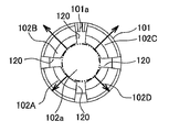
- FIG. 9 is a fragmentary view of the conventional terminal fitting shown in FIG. 7 taken along the direction indicated by the arrow A.
- the terminal fitting 101 comprises, as shown in FIGS. 7 to 9, a cylindrical electrical contact 102 adapted to be connected to a mating terminal fitting (not-shown); and an electrical contact 104 adapted to be connected to an electrical wire (not-shown).
- the terminal fitting 101 is inserted in the terminal accommodating portion of the housing (not-shown) from the side of the electrical contact 102 in a state where the electrical contact 104 is connected to the electrical wire.
- the electrical contact 102 includes four slits 120.
- the four slits 120 are provided in a circumferential direction of the electrical contact 102 at equal intervals.
- the electrical contact 102 is constructed by making the both ends of a conductive metal plate close to each other and joined to each other.
- the one slit 120 out of the four slits also resides at the both ends of the metal plate at the joining portion 101a (illustrated in FIG. 8).
- the slits 120 extend in the longitudinal direction of the electrical contact 102 (cylinder-length direction).
- the four slits 120 have the same size in the longitudinal direction.
- the electrical contact 102 includes, as shown in FIG. 9, four resilient pieces 120A, 120B, 120C, and 120D obtained by virtue of the presence of the four slits 120.
- the inserter of the mating terminal fitting is inserted via the insertion hole 102a (shown in FIG. 8) in the electrical contact 102.
- the inserter biases the resilient pieces 120A, 120B, 120C, and 120D in the diameter-expansion direction of the electrical contact 102.
- the outer surface of the inserter and the inner surface of the electrical contact 102 are brought into contact with each other.
- the terminal fitting 101 is connected to the mating terminal fitting 101.
- the resilient pieces 120A, 120B, 120C, and 120D are energized in the diameter-contraction direction of the electrical contact 102. In this manner, the terminal fitting 101 ensures improved reliability in connection to the mating terminal fitting.
- the above-described state of the art terminal fitting 101 has the following drawbacks. Specifically, in the case of the terminal fitting 101, as shown in FIG. 10, when the inserter of the mating terminal fitting is inserted via the insertion hole 102a into the electrical contact 102, the amount of displacement of the pair of resilient pieces 120B and 120C that are most proximate to the joining portion 101a among the four resilient pieces 120A, 120B, 120C, 120D is larger than those of the other resilient piece 120A, 120D farthest away from the joining portion 101a. In other words, the pair of resilient pieces 120B and 120C are more readily deformed than the other resilient pieces 120A and 120D. This causes variation in the amounts of displacement among the resilient pieces 120A, 120B, 120C, and 120D, which in turn causes the inserter to fail to obtain a uniform contact load among the resilient pieces 120A, 120B, 120C, and 120D.
- An object of the present invention therefore is to provide solution to the above-identified problems.
- one object of the present invention is to provide a terminal fitting that allows for constant contact load of the inserter that is inserted into the electrical contact through making uniform the amounts of displacement of resilient pieces constituting the electrical contact.
- a first aspect of the subject matter provides a terminal fitting that comprises: a cylindrical electrical contact made of a conductive metal plate with both ends thereof made close to each other and joined to each other to define a joining portion of the metal plate, the electrical contact including a plurality of slits provided at intervals in a circumferential direction of the electrical contact, the slits extending in a cylinder-length direction which is a direction along a length of the cylindrical electrical contact.
- the slits one slit that is the farthest away from the joining portion among the slits has a size in the cylinder-length direction larger than those of the remaining slits.
- the invention according to the first aspect has the following construction and advantageous effects.
- the cylindrical electrical contact is provided with the both ends of the conductive metal plate made close to each other and joined to each other thereby forming the joining portion of the metal plate.
- the electrical contact includes the slits provided at intervals in the circumferential direction of the electrical contact.
- the slits extend in the cylinder-length direction.
- One of the slits that is the farthest away from the joining portion among the slits has the size in the cylinder-length direction larger than those of the remaining slits.
- the one resilient piece most proximate to the one slit farthest away from the joining portion of the is allowed to be readily elastically deformed in the electrical contact's diameter-expansion direction and diameter-contraction direction.
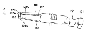
- FIG. 1 is a perspective view of a terminal fitting according to one embodiment of the present invention.
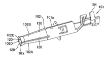
- FIG. 2 is a perspective view of the terminal fitting illustrated in FIG. 1 viewed from another angle.
- FIG. 3 is a perspective view of the terminal fitting illustrated in FIG. 1 viewed from still another angle.
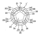
- Fig. 4 is a fragmentary view of the terminal fitting illustrated in FIG. 1 taken along the direction of arrow A in FIG. 1.
- FIG. 5 is an illustration for describing the effects of the terminal fitting of the invention shown in FIG. 1.
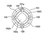
- FIG. 6 is a plan view of a derivative example of the terminal fitting shown in FIG. 1.
- FIG. 7 is a perspective view of a conventional terminal fitting.
- FIG. 8 is a perspective view of the conventional terminal fitting illustrated in FIG. 7 viewed from another angle.
- FIG. 9 is a fragmentary view taken in the direction of an arrow B of the conventional terminal fitting illustrated in FIG. 7.
- FIG. 10 is an illustration for describing the drawbacks found in the conventional terminal fitting shown in FIG. 7.
- the terminal fitting in accordance with one embodiment of the present invention is described hereinbelow with reference to FIGS. 1 to 4.
- the wiring harness comprises: a plurality of electrical wires (not-shown) and connectors (not-shown) each attached to the corresponding one of the ends of the electrical wires.
- the connectors each comprise the terminal fitting 1; a housing (not-shown) that includes a terminal accommodating portion (not-shown) accommodating the terminal fitting 1; and a rear holder (not-shown) adapted to be attached to the housing to prevent the terminal fitting 1 from being detached from the terminal accommodating portion.
- the housing is made of insulating synthetic resin.
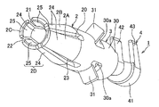
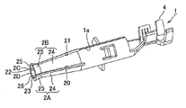
- the terminal fitting 1 comprises, as shown in FIGS. 1 to 3, a cylindrical electrical contact portion 2 adapted to be connected to a mating terminal fitting (not-shown), a cylindrical housing-mounting portion 3 continuing to the electrical contact portion 2, and an electrical-wire-connecting portion 4 continuing to the housing-mounting portion 3 and adapted to be connected to the electrical wire.
- the terminal fitting 1 is inserted into the terminal accommodating portion of the housing from the side of the electrical contact portion 2 in the state where the electrical-wire-connecting portion 4 is connected to the electrical wire.
- the terminal fitting 1 (and accordingly the electrical contact portion 2 thereof) is obtained by punching operation for a conductive metal plate and making both ends of the processed metal plate close to each other and joined to each other.
- the electrical contact portion 2 includes four slits 20, 21, 22, and 23, which are provided at equal intervals in the circumferential direction of the electrical contact portion 2.
- the both ends of the metal plate also resides at the joining portion (hereafter called “joining portion 1a").
- the four slits 20, 21, 22, and 23 extend in the longitudinal direction N of the electrical contact portion 2 (which may be called "cylinder-length direction").
- the first slit 23 farthest away from the joining portion 1a has a longitudinal direction N larger than those of the remaining three second slits 20, 21, and 22.
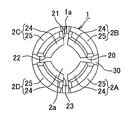
- the electrical contact portion 2 comprises, as shown in FIG. 4, four resilient pieces 2A, 2B, 2C, and 2D defined by the presence of the four slits 20, 21, 22 and 23.
- the resilient pieces 2A, 2B, 2C, and 2D each continue to the housing-mounting portion 3, and each include a base 24 that inclines in a diameter-contraction direction, which is such a direction that, due to the presence of the inclined shape of the base, the diameter of the electrical contact portion 2 is gradually decreased as it becomes away from the housing-mounting portion 3; and a diameter-expansion portion 25 that continues to the base 24 and inclines in the diameter-expansion direction, which is such a direction that, in contrast to the diameter contraction direction, the diameter of the electrical contact portion 2 gradually increases due to the presence of the inclined shape of the diameter-expansion portion 25 as the diameter-expansion portion 25 becomes away from the base 24.
- an inner diameter of the electrical contact portion 2 at one end thereof continuing to the housing-mounting portion 3 is slightly smaller than an outer diameter of an inserter of the mating terminal fitting. It should be noted that, for simplicity, FIG. 4 does not illustrate an abutment piece 31 provided in the housing-mounting portion 3.
- the electrical contact portion 2 includes an insertion hole 2a at the other end of the electrical contact portion 2, the other being distal from the one end continuing to the housing-mounting portion 3, and accordingly the insertion hole 2a is provided at one end of the terminal fitting 1.
- the inserter of the mating terminal fitting is inserted via the insertion hole 2a into the electrical contact portion 2.
- the inserter is elastically brought into contact with each of the resilient pieces 2A, 2B, 2C, and 2D. In this manner, the mating terminal fitting and the terminal fitting 1 are placed in electrical connection to each other.
- the housing-mounting portion 3 includes a cylindrical circumferential wall 30 continuing to the four resilient pieces 2A, 2B, 2C, and 2D; and three abutment pieces 31 each defined by an integral portion of the circumferential wall 30 bent radially outward of the housing-mounting portion 3.
- the circumferential wall 30 includes three openings 30a extending through the circumferential wall 30.
- the three openings 30a are provided in the circumferential direction of the circumferential wall 30 at equal intervals.
- the abutment pieces 31 protrude from one edge of the opening 30a, the one edge being proximate to the electrical contact portion 2, and extend radially outward of the housing-mounting portion 3.
- the abutment pieces 31 are adapted to be brought into abutment on the rear holder when the electrical wire attached to the terminal fitting 1 is pulled and the terminal fitting 1 is moved in the direction indicated by the arrow N.
- the electrical-wire-connecting portion 4 comprises a base wall 41 continuing to the circumferential wall 30 and adapted to position the electrical wire on its surface; a pair of core-wire-clamping pieces 42 protruding upward from the both ends in the width direction of the base wall 41 and adapted to clamp the core wire of the electrical wire therebetween; and a pair of insulating-sheath-clamping pieces 43 protruding upward from the both ends of the base wall 41 in its width direction and adapted to clamp the insulating sheath of the electrical wire.
- the base wall 41 has a shape of a gutter with cross section in a shape of a circular arc.
- the pair of core-wire-clamping pieces 42 are provided more proximate to the housing-mounting portion 3 than the pair of insulating-sheath-clamping pieces 43 are.
- the core-wire-clamping pieces 42 are bent in the direction where the core wire of the electrical wire is pressed against the base wall 41, i.e., in the direction in which the core wire of the electrical wire is clamped by the core-wire-clamping pieces 42, and the electrical-wire-connecting portion 4 is electrically connected to the electrical wire.
- FIGS. 1 to 3 illustrate the state where the core-wire-clamping pieces 42 and the insulating-sheath-clamping pieces 43 are yet to clamp the electrical wire.
- the inserter of the mating terminal fitting is moved close to the electrical contact portion 2 of the terminal fitting 1 that is in a state where the terminal fitting 1 is connected to the end of the electrical wire, and the inserter is inserted via the insertion hole 2a into the electrical contact portion 2, and the outer surface of the inserter and the inner surface of the electrical contact portion 2 are brought into contact with each other.
- the inserter biases the resilient pieces 2A, 2B, 2C, and 2D in the diameter-expansion direction. In this manner, the inserter during the insertion operation makes the resilient pieces 2A, 2B, 2C, and 2D elastically deformed in the diameter-expansion direction.
- the resilient pieces 2A, 2B, 2C, and 2D are energized in the diameter-contraction direction. In this manner, the terminal fitting 1 is connected to the mating terminal fitting.
- the pair of resilient pieces 2A and 2D most proximate to the first slit 23 among the resilient pieces become more readily elastically deformed in the diameter-expansion direction and diameter-contraction direction of the electrical contact portion 2.
- the electrical contact portion 2 in the above-described embodiment is formed in a cylindrical shape, the present invention is not limited to this specific configuration, and the electrical contact portion 2 may take a prismatic shape.
- the above-described embodiment provides the four slits 20, 21, 22, and 23, the present invention is not limited to this specific configuration: It suffices that at least three of the slits 20, 21, 22, and 23 are provided. Further, although the slit 21 in the above-described embodiment is provided in the joining portion 1a, the present invention is not limited to this specific configuration: The slits 20, 21, 22, and 23 may be provided at a location other than the joining portion 1a.
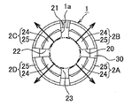
- the electrical contact portion 2 may comprise five resilient pieces 2A, 2B, 2C, 2D, and 2E by virtue of the five slits 20, 21, 22, 23, and 26.
- the two first slits 23 and 26 farthest away from the joining portion 1a has a longitudinal direction N larger than those of the remaining three second slits 20, 21, and 22.
- the two first slits 23, 26 may be provided.
- FIG. 6 does not illustrate the abutment piece 31 of the housing-mounting portion 3 for simplicity.
Landscapes
- Engineering & Computer Science (AREA)
- Manufacturing & Machinery (AREA)
- Connector Housings Or Holding Contact Members (AREA)
- Details Of Connecting Devices For Male And Female Coupling (AREA)
Abstract
La présente invention porte sur une garniture de borne qui assure une charge de contact constante d'un dispositif d'introduction qui est introduit dans un contact électrique en rendant uniforme les quantités de déplacement parmi une pluralité de pièces souples constituant le contact électrique. Une garniture de borne 1,1' comprend une partie de contact électrique cylindrique 2 obtenue en rendant les deux extrémités d'une plaque métallique conductrice proches l'une de l'autre et assemblées l'une à l'autre. La partie de contact électrique 2 comprend une pluralité de fentes 20, 21, 22, 23 et 26 s'étendant dans une direction de longueur de cylindre N et disposées à des intervalles dans la direction périphérique de la partie de contact électrique 2. Parmi les fentes 20, 21, 22, 23, 26, les fentes 23, 26 disposées les plus éloignées de la partie de jonction au niveau des deux extrémités de la plaque métallique ont une dimension dans la direction de longueur de cylindre N supérieure à celle des autres fentes 20, 21 et 22.
Priority Applications (3)
| Application Number | Priority Date | Filing Date | Title |
|---|---|---|---|
| CN201280018962.9A CN103493301A (zh) | 2011-04-22 | 2012-04-17 | 端子配件 |
| EP12718413.3A EP2700128B1 (fr) | 2011-04-22 | 2012-04-17 | Garniture de borne |
| US14/112,756 US20140038473A1 (en) | 2011-04-22 | 2012-04-17 | Terminal fitting |
Applications Claiming Priority (2)
| Application Number | Priority Date | Filing Date | Title |
|---|---|---|---|
| JP2011095944A JP2012227090A (ja) | 2011-04-22 | 2011-04-22 | 端子金具 |
| JP2011-095944 | 2011-04-22 |
Publications (1)
| Publication Number | Publication Date |
|---|---|
| WO2012144192A1 true WO2012144192A1 (fr) | 2012-10-26 |
Family
ID=46025843
Family Applications (1)
| Application Number | Title | Priority Date | Filing Date |
|---|---|---|---|
| PCT/JP2012/002638 Ceased WO2012144192A1 (fr) | 2011-04-22 | 2012-04-17 | Garniture de borne |
Country Status (5)
| Country | Link |
|---|---|
| US (1) | US20140038473A1 (fr) |
| EP (1) | EP2700128B1 (fr) |
| JP (1) | JP2012227090A (fr) |
| CN (1) | CN103493301A (fr) |
| WO (1) | WO2012144192A1 (fr) |
Cited By (2)
| Publication number | Priority date | Publication date | Assignee | Title |
|---|---|---|---|---|
| WO2016115269A2 (fr) | 2015-01-16 | 2016-07-21 | Amphenol Corporation | Contact électrique ayant des dents à bords de longueurs différentes |
| EP3054535A1 (fr) * | 2015-02-03 | 2016-08-10 | Yamaichi Electronics Deutschland GmbH | Contact femelle et procede de production |
Families Citing this family (13)
| Publication number | Priority date | Publication date | Assignee | Title |
|---|---|---|---|---|
| ES2635625T3 (es) * | 2013-07-30 | 2017-10-04 | Abb Schweiz Ag | Dispositivo de conexión para un aparato conmutador |
| JP6086244B2 (ja) | 2013-11-19 | 2017-03-01 | 住友電装株式会社 | 多接点型端子 |
| DE102015201635A1 (de) * | 2015-01-30 | 2016-08-04 | Te Connectivity Germany Gmbh | Kontaktelement und Bestückungsanordnung mit selbigem |
| JP2016197542A (ja) | 2015-04-03 | 2016-11-24 | 住友電装株式会社 | コネクタ |
| JP2017010703A (ja) * | 2015-06-19 | 2017-01-12 | 矢崎総業株式会社 | 端子及び端子接続構造 |
| CN108123249A (zh) * | 2018-01-31 | 2018-06-05 | 四川永贵科技有限公司 | 耐振动防水冲压插孔 |
| JP7066596B2 (ja) * | 2018-11-16 | 2022-05-13 | ホシデン株式会社 | コネクタ |
| JP2020149852A (ja) * | 2019-03-13 | 2020-09-17 | 株式会社オートネットワーク技術研究所 | コネクタ及びコネクタ装置 |
| WO2020235355A1 (fr) * | 2019-05-22 | 2020-11-26 | 住友電装株式会社 | Borne de connexion et connecteur |
| JP7292190B2 (ja) * | 2019-11-29 | 2023-06-16 | ホシデン株式会社 | グランド端子及びこれを備えたコネクタ |
| JP2023003170A (ja) * | 2021-06-23 | 2023-01-11 | 株式会社オートネットワーク技術研究所 | 端子金具 |
| JP7622577B2 (ja) * | 2021-07-29 | 2025-01-28 | 住友電装株式会社 | 充電コネクタ |
| US20230402768A1 (en) * | 2022-06-10 | 2023-12-14 | Fci Usa Llc | Cylindrical stamped electrical power terminal |
Citations (4)
| Publication number | Priority date | Publication date | Assignee | Title |
|---|---|---|---|---|
| US6190215B1 (en) * | 1997-01-31 | 2001-02-20 | Berg Technology, Inc. | Stamped power contact |
| US6475039B1 (en) * | 1998-02-24 | 2002-11-05 | Radiall | Electrical connector contact pin |
| JP2004047355A (ja) | 2002-07-15 | 2004-02-12 | Ono Seisakusho:Kk | コネクターとその製造方法 |
| US20110028039A1 (en) * | 2007-09-05 | 2011-02-03 | Preci Dip Sa | Contact clip |
Family Cites Families (4)
| Publication number | Priority date | Publication date | Assignee | Title |
|---|---|---|---|---|
| JP2967507B2 (ja) * | 1995-08-16 | 1999-10-25 | 日本航空電子工業株式会社 | 電気ソケット用雌型コンタクト |
| JP5270480B2 (ja) * | 2008-11-05 | 2013-08-21 | 富士通コンポーネント株式会社 | コネクタ |
| DE102009030463A1 (de) * | 2009-06-25 | 2010-12-30 | Lapp Engineering & Co. | Elektrischer Steckverbinder |
| JP5286190B2 (ja) * | 2009-08-03 | 2013-09-11 | 富士通コンポーネント株式会社 | 同軸コネクタ、及びコネクタ装置 |
-
2011
- 2011-04-22 JP JP2011095944A patent/JP2012227090A/ja active Pending
-
2012
- 2012-04-17 EP EP12718413.3A patent/EP2700128B1/fr active Active
- 2012-04-17 US US14/112,756 patent/US20140038473A1/en not_active Abandoned
- 2012-04-17 CN CN201280018962.9A patent/CN103493301A/zh active Pending
- 2012-04-17 WO PCT/JP2012/002638 patent/WO2012144192A1/fr not_active Ceased
Patent Citations (4)
| Publication number | Priority date | Publication date | Assignee | Title |
|---|---|---|---|---|
| US6190215B1 (en) * | 1997-01-31 | 2001-02-20 | Berg Technology, Inc. | Stamped power contact |
| US6475039B1 (en) * | 1998-02-24 | 2002-11-05 | Radiall | Electrical connector contact pin |
| JP2004047355A (ja) | 2002-07-15 | 2004-02-12 | Ono Seisakusho:Kk | コネクターとその製造方法 |
| US20110028039A1 (en) * | 2007-09-05 | 2011-02-03 | Preci Dip Sa | Contact clip |
Cited By (3)
| Publication number | Priority date | Publication date | Assignee | Title |
|---|---|---|---|---|
| WO2016115269A2 (fr) | 2015-01-16 | 2016-07-21 | Amphenol Corporation | Contact électrique ayant des dents à bords de longueurs différentes |
| EP3437160A4 (fr) * | 2015-01-16 | 2019-11-13 | Amphenol Corporation | Contact électrique ayant des dents à bords de longueurs différentes |
| EP3054535A1 (fr) * | 2015-02-03 | 2016-08-10 | Yamaichi Electronics Deutschland GmbH | Contact femelle et procede de production |
Also Published As
| Publication number | Publication date |
|---|---|
| EP2700128A1 (fr) | 2014-02-26 |
| US20140038473A1 (en) | 2014-02-06 |
| CN103493301A (zh) | 2014-01-01 |
| EP2700128B1 (fr) | 2015-03-04 |
| JP2012227090A (ja) | 2012-11-15 |
Similar Documents
| Publication | Publication Date | Title |
|---|---|---|
| EP2700128B1 (fr) | Garniture de borne | |
| EP2747206B1 (fr) | Borne | |
| US7601029B2 (en) | Electric connector assembly kit and shielded cable harness | |
| CN101926062B (zh) | 同轴连接器以及同轴连接器的组装方法 | |
| US7192301B2 (en) | Electrical connector | |
| US11784426B2 (en) | Electrical cable assembly, method and apparatus for making same and electrical terminal for same | |
| KR20100129739A (ko) | 후프 부재, 내부 전도체 터미널 및 동축 커넥터 제조 방법 | |
| US20100015863A1 (en) | Female type terminal pin | |
| US7118409B2 (en) | Connector and cable retainer | |
| JP6943175B2 (ja) | 端子金具及びコネクタ | |
| JP2009099300A (ja) | シールドコネクタ | |
| JP4965226B2 (ja) | 外導体端子 | |
| US8263865B2 (en) | Wire connection unit | |
| WO2007089825A1 (fr) | Contact électrique avec bride de câble | |
| JP2016009527A (ja) | コネクタ | |
| US20170054225A1 (en) | Joint connector and wire harness | |
| EP4117123B1 (fr) | Structure de fixation de connecteurs | |
| KR102338051B1 (ko) | 동축 커넥터 및 동축 케이블을 구비한 동축 커넥터 | |
| JP5390792B2 (ja) | 接続部材 | |
| US20160181710A1 (en) | Printed Circuit Board Assembly Having Improved Terminals | |
| US7351100B2 (en) | Electric connector | |
| US7708591B2 (en) | Shield connector | |
| JP4392381B2 (ja) | シールドコネクタ | |
| JP7265132B2 (ja) | ケーブルコネクタ及びそれ備えた車載カメラモジュール用コネクタ | |
| JP2012028084A (ja) | コネクタ |
Legal Events
| Date | Code | Title | Description |
|---|---|---|---|
| 121 | Ep: the epo has been informed by wipo that ep was designated in this application |
Ref document number: 12718413 Country of ref document: EP Kind code of ref document: A1 |
|
| WWE | Wipo information: entry into national phase |
Ref document number: 14112756 Country of ref document: US |
|
| NENP | Non-entry into the national phase |
Ref country code: DE |
|
| WWE | Wipo information: entry into national phase |
Ref document number: 2012718413 Country of ref document: EP |