WO2012141163A1 - 光コネクタ及びフェルール - Google Patents
光コネクタ及びフェルール Download PDFInfo
- Publication number
- WO2012141163A1 WO2012141163A1 PCT/JP2012/059748 JP2012059748W WO2012141163A1 WO 2012141163 A1 WO2012141163 A1 WO 2012141163A1 JP 2012059748 W JP2012059748 W JP 2012059748W WO 2012141163 A1 WO2012141163 A1 WO 2012141163A1
- Authority
- WO
- WIPO (PCT)
- Prior art keywords
- connector
- ferrule
- shaft portion
- flange
- optical
- Prior art date
- Legal status (The legal status is an assumption and is not a legal conclusion. Google has not performed a legal analysis and makes no representation as to the accuracy of the status listed.)
- Ceased
Links
Images












Classifications
-
- G—PHYSICS
- G02—OPTICS
- G02B—OPTICAL ELEMENTS, SYSTEMS OR APPARATUS
- G02B6/00—Light guides; Structural details of arrangements comprising light guides and other optical elements, e.g. couplings
- G02B6/24—Coupling light guides
- G02B6/36—Mechanical coupling means
- G02B6/38—Mechanical coupling means having fibre to fibre mating means
- G02B6/3807—Dismountable connectors, i.e. comprising plugs
- G02B6/381—Dismountable connectors, i.e. comprising plugs of the ferrule type, e.g. fibre ends embedded in ferrules, connecting a pair of fibres
-
- G—PHYSICS
- G02—OPTICS
- G02B—OPTICAL ELEMENTS, SYSTEMS OR APPARATUS
- G02B6/00—Light guides; Structural details of arrangements comprising light guides and other optical elements, e.g. couplings
- G02B6/24—Coupling light guides
- G02B6/36—Mechanical coupling means
- G02B6/38—Mechanical coupling means having fibre to fibre mating means
- G02B6/3807—Dismountable connectors, i.e. comprising plugs
- G02B6/3869—Mounting ferrules to connector body, i.e. plugs
-
- G—PHYSICS
- G02—OPTICS
- G02B—OPTICAL ELEMENTS, SYSTEMS OR APPARATUS
- G02B6/00—Light guides; Structural details of arrangements comprising light guides and other optical elements, e.g. couplings
- G02B6/24—Coupling light guides
- G02B6/36—Mechanical coupling means
- G02B6/38—Mechanical coupling means having fibre to fibre mating means
- G02B6/3807—Dismountable connectors, i.e. comprising plugs
- G02B6/3873—Connectors using guide surfaces for aligning ferrule ends, e.g. tubes, sleeves, V-grooves, rods, pins, balls
- G02B6/3874—Connectors using guide surfaces for aligning ferrule ends, e.g. tubes, sleeves, V-grooves, rods, pins, balls using tubes, sleeves to align ferrules
- G02B6/3878—Connectors using guide surfaces for aligning ferrule ends, e.g. tubes, sleeves, V-grooves, rods, pins, balls using tubes, sleeves to align ferrules comprising a plurality of ferrules, branching and break-out means
-
- G—PHYSICS
- G02—OPTICS
- G02B—OPTICAL ELEMENTS, SYSTEMS OR APPARATUS
- G02B6/00—Light guides; Structural details of arrangements comprising light guides and other optical elements, e.g. couplings
- G02B6/24—Coupling light guides
- G02B6/36—Mechanical coupling means
- G02B6/38—Mechanical coupling means having fibre to fibre mating means
- G02B6/3807—Dismountable connectors, i.e. comprising plugs
- G02B6/381—Dismountable connectors, i.e. comprising plugs of the ferrule type, e.g. fibre ends embedded in ferrules, connecting a pair of fibres
- G02B6/3818—Dismountable connectors, i.e. comprising plugs of the ferrule type, e.g. fibre ends embedded in ferrules, connecting a pair of fibres of a low-reflection-loss type
- G02B6/3821—Dismountable connectors, i.e. comprising plugs of the ferrule type, e.g. fibre ends embedded in ferrules, connecting a pair of fibres of a low-reflection-loss type with axial spring biasing or loading means
Definitions
- the present invention relates to an optical connector and a ferrule.
- the male-side connector and the female-side connector have a housing in which a ferrule fixed to the tip of the optical fiber exposed from the end of the optical cord formed by surrounding the outer periphery of the optical fiber with a sheath is accommodated.
- a coil spring that urges each ferrule forward in the fitting direction of each connector is accommodated in the housing.
- the tip of the ferrule housed in the male connector and the tip of the ferrule housed in the female connector are pressed against each other by the elastic force of the coil spring.
- the optical fiber accommodated in the male connector and the optical fiber accommodated in the female connector are optically connected.
- the coil spring is accommodated in both the male connector and the female connector. For this reason, a space for securing the stroke of the coil spring is required for both connectors. Since the space for securing the stroke of the coil spring is formed to extend in the fitting direction of the male connector and the female connector, there is a problem that it is difficult to reduce the size in the fitting direction of both connectors.
- the present invention has been completed based on the above-described circumstances, and an object thereof is to provide an optical connector that is securely held and has a reduced size. It is another object of the present invention to provide a ferrule that is securely held by an optical connector.
- the present invention is an optical connector including a first connector and a second connector that fit together, and each of the first connector and the second connector includes an optical fiber having an outer periphery of an optical fiber surrounded by a sheath. The end of the optical cord located on the side attached to the first connector and the second connector is connected to the tip of the optical fiber exposed from the sheath.
- a ferrule accommodated in both the first connector and the second connector is fixed, and the ferrule has a flange projecting radially outward of the ferrule and a direction opposite to the tip of the ferrule from the flange.
- a shaft portion extending along the axial direction of the ferrule, and the first connector is externally fitted to the shaft portion to connect the ferrule to the first core.
- a coil spring that urges forward in the fitting direction of the kuta, and a spring receiving portion that holds the coil spring from the rear in the fitting direction of the first connector, and the second connector holds the ferrule.
- the ferrule is securely held by the second connector by the holding portion.
- the ferrule can be securely held by the second connector and the optical connector can be downsized as a whole.
- the cross-sectional shape of the shaft portion is a regular polygonal shape in which each vertex in the cross-section of the shaft portion abuts on the inner periphery of the coil spring, and the holding portion is formed on the second connector and formed on the flange.
- the flange receiving portion is in contact with the second connector from the rear in the fitting direction, and a portion of the flange receiving portion facing the shaft portion is formed following the outer shape of the shaft portion.
- the flange of the ferrule shared by both the first optical connector and the second optical connector is locked to the flange receiving portion formed in the first housing of the first optical connector. ing.
- each vertex in the cross section of the shaft portion has a regular polygonal shape that abuts the inner periphery of the coil spring, the axis of the coil spring and the axis of the shaft portion can be aligned. Thereby, the axis of a ferrule and the axis of a coil spring can be made to correspond. As a result, since the ferrule can be held at the normal position, the optical connection between the optical fiber attached to the first connector and the optical fiber attached to the second connector can be reliably maintained.
- the regular polygon shape includes a shape in which the vertex of the regular polygon is chamfered. That is, it includes a case where the vertex is chamfered so that it is not strictly a regular polygon shape but is substantially recognized as a regular polygon shape.
- the surface formed at the apex of the regular polygon may be a flat surface or a curved surface.
- the surface formed at each vertex may form a part of a circle.
- a plurality of arcuate shapes having the same shape may be cut out with respect to one circle, with the center of the circle being the center of point symmetry, so that each vertex of the regular polygon is chamfered.
- the shaft section has a regular polygonal shape. For this reason, the projection area with respect to the flange of a shaft part is small compared with the case where the section of a shaft part is circular. Thereby, the engagement margin of a flange and a flange receiving part can be increased. Since the portion of the flange receiving portion that faces the shaft portion is formed following the outer shape of the shaft portion, the region of the shaft portion in which the projected area with respect to the flange is reduced can be used as the engagement allowance. As a result, the ferrule can be reliably held on the second connector.
- a sleeve into which both the ferrule accommodated in the first connector and the ferrule accommodated in the second connector are inserted is accommodated in the second connector.
- the ferrule accommodated in the first connector and the ferrule accommodated in the second connector are accommodated in the sleeve accommodated in the second connector. Inserted. Then, the tip of the ferrule accommodated in the first connector comes into contact with the tip of the ferrule accommodated in the second connector. Since both ferrules are guided by the inner surface of the sleeve, the axes of both ferrules can be reliably aligned. As a result, the optical fiber attached to the first connector and the optical fiber attached to the second connector can be reliably optically connected.
- the second connector is formed with a flange accommodating portion that accommodates the flange, and a surface of the flange accommodating portion that faces the flange is formed following the outer shape of the flange. preferable.
- the flange since the flange only needs to be accommodated in the flange accommodating portion having a shape that follows the outer shape of the flange, when the flange is accommodated in the flange accommodating portion, the posture of the flange can be easily set to the normal position. Can be held in.
- the holding portion is a locking member that is formed separately from the second connector, is locked to the shaft portion, and is larger than the flange in the radial direction of the ferrule,
- the second connector includes a locking member receiving portion that comes into contact with the locking member from the rear in the fitting direction of the second connector.
- the ferrule is securely held by the locking member receiving portion via the locking member.
- the ferrule can be securely held by the second connector and the optical connector can be downsized as a whole.
- the locking member is formed with a shaft housing groove for housing the shaft.
- the ferrule and the locking member can be locked by a simple configuration in which the shaft portion is housed in the shaft portion housing groove.
- the locking member is formed such that a pair of opening edge portions of the shaft portion receiving groove can be expanded and deformed, and a distance between the pair of opening edge portions in a natural state is based on an outer diameter of the shaft portion Is preferably formed to be small.
- the shaft portion of the ferrule is pressed against the pair of opening edges of the shaft portion receiving groove. Then, the pair of opening edge portions are expanded and deformed. When the shaft portion is further pressed, the shaft portion passes between the opening edges that have been expanded and deformed, and enters the inside of the shaft portion receiving groove. Further, when the shaft portion enters the inside of the shaft portion receiving groove, the pair of opening edges are restored and deformed, and the shaft portion is held inside the shaft portion receiving groove.
- the shaft portion can be reliably held by the locking member.
- a surface of the shaft portion receiving groove facing the shaft portion is formed following the outer shape of the shaft portion.
- the area where the flange and the locking member come into contact can be increased. Thereby, a ferrule can be reliably hold
- a shaft portion insertion hole through which the shaft portion is inserted is formed in the locking member so as to penetrate the locking member.
- the area where the flange and the locking member come into contact can be increased. Thereby, a ferrule can be reliably hold
- At least one of the present invention is a ferrule that is externally fitted and fixed to an end of an optical fiber, and a shaft portion on which a coil spring is externally fitted extends in the axial direction of the ferrule.
- the cross-sectional shape of the shaft portion is a regular polygonal shape in which each vertex in the cross-section of the shaft portion abuts on the inner periphery of the coil spring.
- each vertex in the cross section of the shaft portion has a regular polygonal shape that abuts the inner periphery of the coil spring, so that the axis of the coil spring and the axis of the shaft portion are aligned. Can do.
- the axis of a ferrule and the axis of a coil spring can be made to correspond.
- the ferrule can be held at the normal position, the optical connection between the optical fiber attached to the first connector and the optical fiber attached to the second connector can be reliably maintained.
- the ferrule can be securely held in the optical connector.
- the optical connector can be reduced in size.
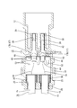
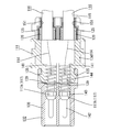
- FIG. 1 is a side sectional view showing an optical connector according to Embodiment 1 of the present invention.
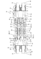
- FIG. 2 is a plan sectional view showing the optical connector according to the first embodiment.
- FIG. 3 is a plan sectional view showing the female connector according to the first embodiment.
- FIG. 4 is an exploded perspective view showing the optical cord and the inner ring and the outer ring.
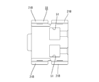
- FIG. 5 is a plan view showing the female-side lower housing.
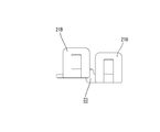
- FIG. 6 is a side view showing the female lower housing.
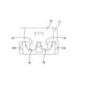
- FIG. 7 is a rear view showing the female lower housing.
- FIG. 8 is a bottom view showing the female-side upper housing.
- FIG. 9 is a side view showing the female-side upper housing.
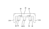
- FIG. 10 is a rear view showing the female-side upper housing.
- FIG. 10 is a rear view showing the female-side upper housing.
- FIG. 11 is a plan view showing the male side lower housing.
- FIG. 12 is a side view showing the male lower housing.
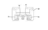
- FIG. 13 is a bottom view showing the male upper housing.
- FIG. 14 is a side view showing the male upper housing.
- FIG. 15 is a front view showing the male upper housing.
- FIG. 16 is a side view showing the ferrule.
- FIG. 17 is a cross-sectional view showing a ferrule.
- FIG. 18 is a rear view showing the ferrule.
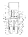
- FIG. 19 is a cross-sectional view showing an optical connector according to Embodiment 2 of the present invention.
- FIG. 20 is a cross-sectional view showing the female connector according to the second embodiment.
- FIG. 21 is an exploded perspective view showing the optical cord and the inner ring and the outer ring.
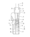
- FIG. 22 is a sectional view showing the male connector according to the second embodiment.
- FIG. 23 is a cross-sectional view showing the male connector according to the second embodiment.
- FIG. 24 is a front view showing a front housing according to the second embodiment.
- FIG. 25 is a side view showing the ferrule.
- FIG. 26 is a rear view showing the ferrule.
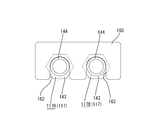
- FIG. 27 is a rear view showing a locking member and a ferrule according to the second embodiment.
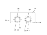
- FIG. 28 is a rear view showing the locking member and the ferrule according to the third embodiment.
- FIG. 29 is a rear view showing a locking member and a ferrule according to the fourth embodiment.
- FIG. 30 is a rear view showing a locking member and a ferrule according to the fifth embodiment.
- An optical connector 10 includes a male connector 11 (an example of a first connector) and a female connector 13 (an example of a second connector) including a hood portion 12 into which the male connector 11 is fitted. And comprising.
- the male connector 11 and the female connector 13 are each attached to an end portion of an optical cord 16 in which the outer periphery of the optical fiber 14 is surrounded by a sheath 15.
- Ferrules 17 ⁇ / b> A and 17 ⁇ / b> B are attached to the end of the optical fiber 14 exposed from the sheath 15 by peeling off the sheath 15 at the end of the optical cord 16 positioned on the side attached to the male connector 11 and the female connector 13. Is fixed.
- the ferrule 17A is accommodated in the male connector 11, and the ferrule 17B is accommodated in the female connector 13.
- the ferrules 17A and 17B have the same shape and size, and are shared by the male connector 11 and the female connector 13.
- ferrule 17A and 17B structures common to the ferrules 17A and 17B may be collectively described as the ferrule 17.
- the upper side in FIG. 1 is the upper side
- the lower side is the lower side.
- the front-back direction the front is made into the front about the fitting direction of each connector 11 and 13, and back is made into the back about a fitting direction. Therefore, the front-rear direction of the male connector 11 and the front-rear direction of the female connector 13 are opposite to each other.
- the female connector 13 includes a synthetic resin female lower housing 18 provided with a hood portion 12 that opens forward in the fitting direction (rightward in FIG. 1), and a synthetic resin that is assembled to the female lower housing 18 from above. And a female upper housing 19 made of metal. As shown in FIG. 7, a lock projection 20 ⁇ / b> A is formed on the outer surface of the female-side lower housing 18. Further, as shown in FIG. 9, the female upper housing 19 is formed with a lock receiving portion 21A at a position corresponding to the lock protrusion 20A. The lock projection 20A and the lock receiving portion 21A are elastically engaged, so that the female side lower housing 18 and the female side upper housing 19 are assembled together.
- the female connector 13 contains an optical cord 16, an optical fiber 14 exposed from the end of the optical cord 16, and a ferrule 17 ⁇ / b> B that is externally fitted and fixed to the tip of the optical fiber 14. Yes.
- the sheath 15 of the optical cord 16 is formed with a through hole 22 extending along the axial direction of the optical cord 16.
- One optical fiber 14 is inserted into the through hole 22.
- a tensile strength material 23 that suppresses the optical fiber 14 from being cut when a tension is applied to the optical cord 16.
- the tensile strength material 23 has a fibrous shape.
- a slit 24 extending along the axial direction of the optical cord 16 is formed at the end of the sheath 15.
- the tensile strength material 23 is pulled out from the slit 24, the tensile strength material 23 is arranged between the metal outer ring 25 and the metal inner ring 26, and the outer ring 25 is caulked to the inner ring 26. A tensile strength material 23 is sandwiched between the outer ring 25 and the inner ring 26. Further, the outer ring 25 is fixed to the sheath 15 by being caulked to the sheath 15 while being fitted to the sheath 15.
- an outer ring receiving groove 28 for receiving the outer ring 25 is provided in the front-back direction (in FIG. 1). It is formed extending in the left-right direction.
- a fitting tube portion 29 is formed in the hood portion 12 so as to protrude forward in the fitting direction of the female connector 13 (rightward in FIG. 1).
- a sleeve 30 into which the ferrule 17 is inserted is accommodated in the fitting tube portion 29. Inside the sleeve 30, both the ferrule 17A and the ferrule 17B are accommodated.
- the sleeve 30 has a substantially cylindrical shape, and is formed of a material that can be elastically deformed in the radial direction, such as metal or ceramic.
- a pair of locking pieces 31 projecting in the vertical direction is formed at the rear end portion (left end portion in FIG. 4) of the sleeve 30. The locking piece 31 is brought into contact with the rear wall of the hood portion 12 from the rear (from the left in FIG. 1), thereby restricting the sleeve 30 from moving forward (to the right in FIG. 1). It has become.
- the male connector 11 includes a synthetic resin front housing 32 fitted into the hood portion 12 and a synthetic resin male housing assembled to the rear of the front housing 32 (to the right in FIG. 1).
- an optical cord 16 Inside the male connector 11, an optical cord 16, an optical fiber 14 exposed from the end of the optical cord 16, and a ferrule 17A externally fitted and fixed to the tip of the optical fiber 14 are accommodated. Yes.
- An inner ring 26 and an outer ring 25 are attached to the end of the optical fiber 14. Since the optical fiber 14, the ferrule 17A, the inner ring 26, and the outer ring 25 have the same configuration as that accommodated in the female connector 13, duplicate description will be omitted.
- an outer ring receiving groove 51 for receiving the outer ring 25 is provided in the front-rear direction (in FIG. 1). It is formed extending in the left-right direction.
- a lock protrusion 20 ⁇ / b> B is formed on the outer surface of the male upper housing 34.
- the male lower housing 33 is formed with a lock receiving portion 21B at a position corresponding to the lock protrusion B20.
- the male upper housing 34 and the male lower housing 33 are assembled together by elastically engaging the lock protrusion 20B and the lock receiving portion 21B.
- the male upper housing 34 is formed with a lock claw 35 protruding forward (leftward in FIG. 13).
- the lock claw 35 is elastically engaged with a lock claw receiving portion (not shown) formed in the front housing 32, whereby the male upper housing 34 and the front housing 32 are assembled together.
- a lock arm 36 extending from the front end (left end in FIG. 1) to the rear (right in FIG. 1) is formed on the upper surface of the front housing 32.
- a claw portion 37 protruding upward is formed at a position near the rear end portion on the upper surface of the lock arm 36.
- the claw portion 37 is elastically engaged with a claw receiving portion 50 formed at a position corresponding to the claw portion 37 in the hood portion 12 of the female side housing, so that the female side connector 13 and the male side connector are engaged. 11 can be held in a fitted state.
- a protective cylinder portion 38 extending forward (leftward in FIG. 1) is formed at the front end portion (left end portion in FIG. 1) of the front housing 32.
- Ferrules 17A and 17B are arranged inside the protective cylinder portion 38. Further, when the male connector 11 and the female connector 13 are fitted, the fitting cylinder portion 29 of the female connector 13 is fitted into the protective cylinder portion 38.
- a spring accommodating portion 40 is formed at the rear end portion (right end portion in FIG. 1) of the front housing 32 so as to open rearward (rightward in FIG. 1) and accommodate the coil spring 39.
- a spring receiving portion 41 that abuts against the rear end portion of the coil spring 39 from the rear is formed at the front end portion (left end portion in FIG. 1) of the male upper housing 34 so as to protrude inward.
- the front end of the coil spring 39 is locked to the ferrule 17 from the rear, and biases the ferrule 17 forward (leftward in FIG. 1).
- the ferrule 17A accommodated in the male connector 11 is inserted into the sleeve 30 when the male connector 11 and the female connector 13 are fitted.
- the tip of the ferrule 17 ⁇ / b> B accommodated in the female connector 13 and the tip of the ferrule 17 ⁇ / b> A accommodated in the male connector 11 come into contact with each other. Since the ferrule 17A is biased by the coil spring 39, the ferrule 17A is pressed against the ferrule 17B. Thereby, the optical fiber 14 on the male connector 11 side and the optical fiber 14 on the female connector 13 side are optically connected.
- the ferrule 17 includes a cylindrical capillary 42, a flange 43 formed by molding a synthetic resin at the rear end of the capillary 42, a flange 43 formed integrally with the flange 43, and a flange. 43 and a shaft portion 44 extending in the direction opposite to the tip of the ferrule 17 and extending along the axial direction of the ferrule 17.
- the cross-sectional shape of the capillary 42 is circular.
- a capillary side insertion hole 45 extending in the axial direction of the capillary 42 is formed in the capillary 42. The optical fiber 14 is inserted into the capillary side insertion hole 45.
- the flange 43 is formed to project outward in the radial direction of the ferrule 17.
- the outer shape of the flange 43 has a square shape.
- a tapered slope is formed on the outer surface of the flange 43 on the capillary 42 side.
- the cross-sectional shape of the shaft portion 44 is a regular polygon.
- the regular polygon shape includes a shape in which the vertex of the regular polygon is chamfered. That is, it is not strictly a regular polygonal shape by chamfering the vertex, but includes a case where it is recognized as a regular polygonal shape. This chamfering may be performed by a flat surface or a curved surface.
- the cross-sectional shape of the shaft portion 44 is a square shape. Thereby, the axial part 44 has comprised the substantially rectangular parallelepiped shape as a whole. Of the shaft portion 44, the ridge portion extending in the longitudinal direction is chamfered.
- the ridge portion of the shaft portion 44 is chamfered by a curved surface.
- the above-described coil spring 39 is fitted on the shaft portion 44.
- a portion corresponding to each apex of the cross section of the shaft portion 44 comes into contact with the inner periphery of the coil spring 39 fitted on the shaft portion 44.
- the cross-sectional shape of the shaft portion 44 has the following shape in detail. That is, for each circle, four arcs having the same shape are cut out with the center of the circle as the center of point symmetry, so that each vertex of the square is chamfered by a curved surface.
- a shaft portion side insertion hole 46 is formed in the shaft portion 44 along the direction in which the shaft portion 44 extends.
- the optical fiber 14 is inserted into the shaft side insertion hole 46.
- the capillary side insertion hole 45 and the shaft side insertion hole 46 are formed coaxially.
- the outer surface on the shaft portion 44 side is formed so as to stand up with respect to the direction in which the shaft portion 44 extends.
- the outer surface on the shaft portion 44 side is formed substantially perpendicular to the direction in which the shaft portion 44 extends.
- an injection hole 47 is formed between the flange 43 and the shaft portion 44 so as to extend in a direction intersecting the axis of the shaft portion 44 and into which an adhesive is injected.
- a flange accommodating portion 48 that accommodates the flange 43 of the ferrule 17 ⁇ / b> B is formed on the lower wall of the female connector 13. More specifically, as shown in FIG. 5, in the female-side lower housing 18, two flange accommodating portions 48 formed in a groove shape opening upward are arranged in the left-right direction (vertical direction in FIG. 5). Is formed.
- the inner surface of the flange accommodating portion 48 is opposed to the flange 43 in a state where the ferrule 17 is accommodated in the flange accommodating portion 48, and is formed in a shape following the outer shape of the flange 43. Specifically, the inner surface of the flange accommodating portion 48 has a substantially rectangular shape.
- a flange receiving portion 49 (an example of a holding portion) that hangs downward is formed on the upper wall of the female upper housing 19.
- the flange receiving portion 49 comes into contact with the flange 43 from the rear of the flange 43 (left side in FIG. 1) in a state where the ferrule 17 is accommodated in the flange accommodating portion 48.
- the flange 43 comes into contact with the flange 43 from the rear in the fitting direction of the female connector 13.
- the ferrule 17B is restricted from moving backward (leftward in FIG. 1) (see FIGS. 2 and 3).
- the flange receiving portion 49 has a generally gate shape. Thereby, it contacts with the upper part of the flange 43, and both sides from back. As a result, the ferrule 17B is reliably restricted from moving backward.
- the flange receiving portion 49 is formed with a rib 52 extending rearward (leftward in FIG. 8). By the rib 52, even when the ferrule 17B is pressed from the front (right side in FIG. 8) by the ferrule 17A accommodated in the male connector 11, it is possible to reliably suppress the flange receiving portion 49 from being deformed (FIG. 2 and FIG. 3).
- the portion of the flange receiving portion 49 that faces the shaft portion 44 has a shape that follows the outer shape of the shaft portion 44.
- a portion of the flange receiving portion 49 that faces the shaft portion 44 is formed in a substantially square shape. As a result, the shaft portion 44 can be easily positioned.
- the rear end portion (the right end portion in FIG. 1) of the coil spring 39 is received by the spring receiving portion 41 described above.
- the coil spring 39 is held by the spring receiving portion 41 from the rear in the fitting direction of the male connector 11.
- the spring receiving portion 41 is formed to hang downward from the upper wall of the male upper housing 34.
- the spring receiving portion 41 is generally gate-shaped.
- the portion of the spring receiving portion 41 that contacts the coil spring 39 has a circular shape following the shape of the coil spring 39.
- the portion of the spring receiving portion 41 that faces the shaft portion 44 of the ferrule 17 ⁇ / b> A is formed in a substantially quadrangular shape whose upper portion is rounded following the outer shape of the shaft portion 44.
- the spring accommodating portion 40 in which the coil spring 39 is accommodated is formed in a shape that follows the outer shape of the coil spring 39. As a result, the coil spring 39 is restrained from moving in a direction intersecting the axis of the coil spring 39.
- the ferrule 17B is configured such that, in the female connector 13, the flange receiving portion 49 formed on the female upper housing 19 abuts from the rear (left side in FIGS. 1 and 2), thereby Is held in a restricted state. Further, the front portion of the flange 43 is in contact with the rear wall of the hood portion 12 formed in the female side lower housing 18 from the rear (left side in FIGS. 1 and 2). This restricts the ferrule 17B from moving forward (rightward in FIGS. 1 and 2). In this way, the ferrule 17B is securely held by the female connector 13.
- the coil spring 39 for latching the ferrule 17B becomes unnecessary.
- an area for securing the stroke of the coil spring 39 is not required, and the female connector 13 can be downsized.
- the optical connector 10 can be reduced in size as a whole.
- the cross section of the shaft portion 44 has a regular polygonal shape. For this reason, compared with the case where the cross section of the axial part 44 has comprised circular shape, the projection area with respect to the flange 43 of the axial part 44 is small. Thereby, the engagement margin of the flange 43 and the flange receiving part 49 can be increased. Since the portion of the flange receiving portion 49 that faces the shaft portion 44 is formed following the outer shape of the shaft portion 44, the region of the shaft portion 44 in which the projected area with respect to the flange 43 is reduced can be reliably engaged. It can be used as a bill. As a result, the ferrule 17B can be reliably held on the female connector 13.
- each vertex in the cross section of the shaft portion 44 of the ferrule 17A has a regular polygonal shape that comes into contact with the inner periphery of the coil spring 39.
- the axis of the coil spring 39 and the axis of the shaft portion 44 can be aligned.
- the axis of ferrule 17A and the axis of coil spring 39 can be made to correspond.
- the ferrule 17A can be held at the normal position, the optical connection between the optical fiber 14 attached to the male connector 11 and the optical fiber 14 attached to the female connector 13 can be reliably maintained.
- the regular polygon shape includes a shape in which the vertex of the regular polygon is chamfered. That is, it includes a case where the vertex is chamfered so that it is not strictly a regular polygon shape but is substantially recognized as a regular polygon shape. This chamfering process may be performed by a flat surface or a curved surface.
- the female connector 13 accommodates the sleeve 30 into which the ferrules 17A and 17B are inserted. Accordingly, when the male connector 11 and the female connector 13 are fitted, the ferrule 17A accommodated in the male connector 11 and the female connector 13 are accommodated in the sleeve 30 accommodated in the female connector 13. The ferrule 17B is inserted. Then, the tip of the ferrule 17A accommodated in the male connector 11 and the tip of the ferrule 17B accommodated in the female connector 13 come into contact with each other. Since both ferrules 17A and 17B are guided by the inner surface of the sleeve 30, the axes of the ferrules 17A and 17B can be reliably aligned. As a result, the optical fiber 14 attached to the male connector 11 and the optical fiber 14 attached to the female connector 13 can be reliably optically connected.
- the female connector 13 is formed with the flange accommodating portion 48 that accommodates the flange 43 of the ferrule 17, and the surface of the flange accommodating portion 48 that faces the flange 43 is a flange. It is formed following the outer shape of 43. Accordingly, the flange 43 of the ferrule 17 may be accommodated in the flange accommodating portion 48 having a shape that follows the outer shape of the flange 43. Therefore, when the flange 43 is accommodated in the flange accommodating portion 48, the flange 43 Can be easily held at the normal position.
- the optical connector 110 includes a male connector 111 (first connector) and a female connector 113 (second connector) including a hood portion 112 into which the male connector 111 is fitted. .
- the male connector 111 and the female connector 113 are each attached to an end portion of an optical cord 116 in which the outer periphery of the optical fiber 114 is surrounded by a sheath 115.
- ferrules 117A and 117B are attached to the tip of the optical fiber 114 exposed from the sheath 115 when the sheath 115 is peeled off. Is fixed.
- the ferrule 117A is accommodated in the male connector 111
- the ferrule 117B is accommodated in the female connector 113.
- the ferrules 117A and 117B have the same shape and size, and are shared by the male connector 111 and the female connector 113.
- ferrule 117A and 117B structures common to the ferrules 117A and 117B may be collectively described as the ferrule 117.
- the upper side in FIG. 23 is the upper side, and the lower side is the lower side.
- the front-back direction let the front be the front about the fitting direction of each connector 111,113, and let the back be the back about a fitting direction. Therefore, the front-rear direction of the male connector 111 and the front-rear direction of the female connector 113 are opposite to each other.
- the female connector 113 includes a synthetic resin female lower housing 118 provided with a hood portion 112 that opens forward in the fitting direction (rightward in FIG. 19), and a synthetic resin that is assembled to the female lower housing 118 from above. And a female upper housing 119 made of the same material.
- the female lower housing 118 and the female upper housing 119 are integrally assembled by elastically engaging a lock projection (not shown) and a lock receiving portion (not shown).
- an optical cord 116 Inside the female connector 113, an optical cord 116, an optical fiber 114 exposed from the end of the optical cord 116, and a ferrule 117B externally fitted and fixed to the tip of the optical fiber 114 are accommodated. Yes.
- the sheath 115 of the optical cord 116 is formed with a through hole 122 that extends along the axial direction of the optical cord 116.
- One optical fiber 114 is inserted into the through hole 122.
- a tensile strength material 123 that suppresses the optical fiber 114 from being cut when a tension is applied to the optical cord 116 is accommodated.
- the tensile strength material 123 has a fibrous shape.
- a slit 124 extending along the axial direction of the optical cord 116 is formed at the end of the sheath 115.
- the tensile strength material 123 is pulled out from the slit 124, the tensile strength material 123 is arranged between the metal outer ring 125 and the metal inner ring 126, and the outer ring 125 is caulked to the inner ring 126.
- a tensile strength material 123 is sandwiched between the outer ring 125 and the inner ring 126. Further, the outer ring 125 is fixed to the sheath 115 by being caulked to the sheath 115 while being fitted to the sheath 115.
- An outer ring housing groove 128 for housing the outer ring 125 is disposed in the front-rear direction (in FIG. 20) at a position near the rear ends of the female lower housing 118 and the female upper housing 119 (position near the left end in FIG. 20). It is formed extending in the left-right direction.
- a fitting tube portion 129 is formed in the hood portion 112 so as to protrude forward in the fitting direction of the female connector 113 (rightward in FIG. 20).
- a sleeve 130 into which the ferrule 117 is inserted is accommodated in the fitting tube portion 129. Inside the sleeve 130, both the ferrule 117A and the ferrule 117B are accommodated.
- the sleeve 130 has a substantially cylindrical shape, and is formed of a material that can be elastically deformed in the radial direction, such as metal or ceramic.
- a pair of locking pieces 131 protruding outward in the radial direction of the sleeve 130 is formed at the rear end portion (left end portion in FIG. 20) of the sleeve 130.
- the locking piece 131 is configured to abut against the back wall of the hood portion 112 from the rear (from the left in FIG. 20) to restrict the sleeve 130 from moving forward (to the right in FIG. 20).
- the ferrule 117B By arranging the ferrule 117B in the fitting tube portion 129, the ferrule 117B is prevented from colliding with a foreign object. In addition, when the male connector 111 is fitted into the hood portion 112, the front end of the male connector 111 and the ferrule 117B are prevented from colliding even when they are obliquely fitted.
- the male connector 111 includes a synthetic resin front housing 132 fitted into the hood portion 112 and a synthetic resin male housing assembled to the rear of the front housing 132 (to the right in FIG. 19).
- the male connector 111 contains an optical cord 116, an optical fiber 114 exposed from the end of the optical cord 116, and a ferrule 117 ⁇ / b> A that is externally fitted and fixed to the tip of the optical fiber 114. Yes.
- An inner ring 126 and an outer ring 125 are attached to the end of the optical fiber 114. Since the optical fiber 114, the ferrule 117A, the inner ring 126, and the outer ring 125 have the same configuration as that accommodated in the female connector 113, a duplicate description is omitted.
- an outer ring receiving groove 151 for receiving the outer ring 125 is provided in the front-rear direction (in FIG. 22). It is formed extending in the left-right direction.
- the male upper housing 134 and the male lower housing 133 are assembled together by elastically engaging a lock projection (not shown) and a lock receiving portion (not shown).
- the male upper housing 134 is formed with a lock claw 135 protruding forward (leftward in FIG. 22).
- the lock claw 135 is elastically engaged with a lock claw receiving portion (not shown) formed in the front housing 132, whereby the male upper housing 134 and the front housing 132 are assembled together.
- a lock arm 136 is formed on the upper surface of the front housing 132, extending from the front end (left end in FIG. 23) to the rear (right in FIG. 23).
- a claw portion 137 that protrudes upward is formed at a position near the rear end portion on the upper surface of the lock arm 136.
- the claw portion 137 is elastically engaged with a claw receiving portion (not shown) formed at a position corresponding to the claw portion 137 in the hood portion 112 of the female side housing. The state in which the male connector 111 is fitted can be maintained.
- a protective cylinder portion 138 extending forward (leftward in FIG. 22) is formed at the front end portion (left end portion in FIG. 22) of the front housing 132.
- a ferrule 117 ⁇ / b> A is arranged inside the protective cylinder portion 138. Further, in a state where the male connector 111 and the female connector 113 are fitted, the fitting tube portion 129 of the female connector 113 is fitted into the protective tube portion 138.
- the ferrule 117A By arranging the ferrule 117A in the protective cylinder portion 138, it is possible to prevent foreign matter from colliding with the ferrule 117A. Further, when the male connector 111 is fitted into the hood portion 112 of the female connector 113, the ferrule 117A can be prevented from colliding with the inner wall of the hood portion 112.
- a spring accommodating portion 140 is formed that opens rearward (rightward in FIG. 22) and accommodates the coil spring 139. Further, a spring receiving portion 141 that is in contact with the rear end portion of the coil spring 139 from the rear is formed on the front end portion (left end portion in FIG. 19) of the male upper housing 134 so as to protrude inward.
- the spring receiving portion 141 is formed to hang downward from the upper wall of the male upper housing 134.
- the spring receiving portion 141 has a generally gate shape.
- a portion of the spring receiving portion 141 that contacts the coil spring 139 has a circular shape following the shape of the coil spring 139.
- the front end of the coil spring 139 is locked to the ferrule 117 from the rear, and biases the ferrule 117 forward (leftward in FIG. 22).
- the ferrule 117A accommodated in the male connector 111 is inserted into the sleeve 130 when the male connector 111 and the female connector 113 are fitted.
- the tip of the ferrule 117B accommodated in the female connector 113 and the tip of the ferrule 117A accommodated in the male connector 111 are in contact with each other. Since the ferrule 117A is biased by the coil spring 139, the ferrule 117A is pressed against the ferrule 117B. Thereby, the optical fiber 114 on the male connector 111 side and the optical fiber 114 on the female connector 113 side are optically connected.
- the ferrule 117 includes a cylindrical capillary 142, a flange 143 molded by a synthetic resin at the rear end of the capillary 142, a flange 143 formed integrally with the flange 143, and a flange.
- a shaft portion 144 that extends from 143 in the direction opposite to the tip of the ferrule 117 and extends along the axial direction of the ferrule 117.
- the cross-sectional shape of the capillary 142 is circular.
- the capillary 142 is formed with a capillary side insertion hole (not shown) extending in the axial direction of the capillary 142.
- the optical fiber 114 is inserted into the capillary side insertion hole.
- the flange 143 is formed so as to protrude outward in the radial direction of the ferrule 117.
- the outer shape of the flange 143 has a regular hexagonal shape.
- a tapered inclined surface is formed on the outer surface of the flange 143 on the capillary 142 side.
- the rear end portion (right end portion in FIG. 25) of the shaft portion 144 is reduced in diameter.
- the outer diameter size of the front end portion of the shaft portion 144 is set to be substantially the same as the inner diameter size of the coil spring 139.
- the coil spring 139 fitted on the shaft portion 144 comes into contact with the inner periphery.
- a shaft portion side insertion hole (not shown) is formed in the shaft portion 144 along the direction in which the shaft portion 144 extends.
- the optical fiber 114 is inserted into the shaft side insertion hole.
- the capillary side insertion hole and the shaft side insertion hole are formed on the same axis.
- the female side lower housing 118 is formed with a flange accommodating portion 148 that accommodates the flange 143 of the ferrule 117B.
- the female-side lower housing 118 has a locking member housing portion 165 for housing a locking member 160 (an example of a holding portion) that locks with the ferrule 117B behind the flange housing portion 148 (left side in FIG. 20). Prepare.
- the locking member 160 is made of synthetic resin and has a plate shape. As shown in FIG. 27, the locking member 160 is formed with a shaft portion receiving groove 162 that receives the shaft portion 144 of the ferrule 117B and that opens downward. In the present embodiment, two shaft housing grooves 162 are formed side by side. A surface of the shaft portion accommodation groove 162 facing the shaft portion 144 is formed in a substantially rectangular shape. The locking member 160 is formed larger than the flange 143 in the radial direction of the ferrule 117B.
- the front end portion of the female upper housing 119 is brought into contact with the locking member 160 from the rear in the fitting direction of the female connector 113 (left side in FIG. 20), thereby The movement of 160 backward is restricted.
- a front end portion of the female-side upper housing 119 serves as a locking member receiving portion 161.
- An insertion hole 166 through which the shaft portion is inserted is formed in the locking member receiving portion 161 so as to penetrate the locking member 160 shaft portion.
- the ferrule 117 ⁇ / b> B is securely held by the female connector 113 by the locking member receiving portion 161 via the locking member 160. Moreover, since the locking member 160 is formed larger than the flange 143 in the radial direction of the ferrule 117B, the ferrule 117B can be reliably held by the female connector 113.
- the locking member 160 is formed larger than the flange 143, it is not necessary to increase the dimensional accuracy of the female connector 113 in order to form an engagement margin with the flange 143. An increase in the manufacturing cost can be suppressed.
- the coil spring 139 can be omitted in the female connector 113, it is not necessary to ensure the stroke of the coil spring 139. As a result, the female connector 113 can be downsized, and the optical connector 110 can be downsized as a whole.
- the ferrule 117B and the locking member 160 can be locked with a simple configuration in which the shaft portion 144 is housed in the shaft portion housing groove 162.
- the locking member 160 is formed so that the pair of opening edge portions 163 of the shaft portion accommodation groove 162 can be expanded and deformed. And the space
- the shaft portion 144 when the shaft portion 144 is housed in the shaft portion housing groove 162, first, the shaft portion 144 is pressed against the pair of opening edge portions 163 of the shaft portion housing groove 162. Then, the pair of opening edge portions 163 is expanded and deformed. When the shaft portion 144 is further pressed, the shaft portion 144 enters the inside of the shaft portion receiving groove 162 through the space between the opening edge portions 163 that have been expanded and deformed. When the shaft portion 144 further enters the shaft portion receiving groove 162, the pair of opening edge portions 163 is restored and deformed, and the shaft portion 144 is held inside the shaft portion receiving groove 162.
- the shaft portion 144 can be reliably held by the locking member 160.
- the surface of the shaft portion accommodation groove 162 that faces the shaft portion 144 is formed following the outer shape of the shaft portion 144. Thereby, the area which the flange 143 and the locking member 160 contact can be enlarged. Thus, the ferrule 117B can be reliably held by the female connector 113 via the locking member 160.
- the surface of the shaft portion receiving groove 162 that faces the shaft portion is formed in a semicircular shape along the outer shape of the shaft portion.
- the area where the flange 143 and the locking member 160 come into contact can be increased.
- the ferrule 117B can be reliably held by the female connector 113 via the locking member 160.
- the locking member 160 is formed with a shaft portion insertion hole 164 through which the shaft portion is inserted so as to penetrate the locking member 160.
- the inner diameter dimension of the shaft part insertion hole 164 is set to be the same as or slightly larger than the outer diameter dimension of the shaft part.
- the ferrule 117B and the optical fiber 114 can be fixed by inserting the optical fiber 114 through the ferrule 117B after the shaft portion 144 is inserted into the shaft portion insertion hole 164.
- the area where the flange 143 and the locking member 160 come into contact can be increased.
- the ferrule 117B can be reliably held by the female connector 113 via the locking member 160.
- the present invention is not limited to the embodiments described with reference to the above description and drawings.
- the following embodiments are also included in the technical scope of the present invention.
- the cross-sectional shape of the shaft portion 44 is a square shape.
- the shape is not limited to this, and an arbitrary regular polygon shape such as a regular triangle shape, a regular pentagon shape, a regular hexagon shape, or the like is necessary. It can be.
- one optical fiber 14 is arranged in one optical cord 16.
- the present invention is not limited to this, and two or more optical fibers 14 are provided in one optical cord 16. It is good also as a structure arranged.
- each of the male connector 11 and the female connector 13 is configured to accommodate two ferrules.
- the present invention is not limited to this, and one or three or more ferrules 17 are provided. May be configured to be accommodated.
- one optical fiber 114 is arranged in one optical cord 116.
- the present invention is not limited to this, and two or more optical fibers are provided in one optical cord 116. 114 may be arranged.
- the sleeve 130 is accommodated in the female connector 113 in the second to fifth embodiments, the sleeve 130 may be omitted.
- each of the male connector 111 and the female connector 113 is configured to accommodate two ferrules 117.
- the present invention is not limited to this.
- One, three, or more The ferrule 117 may be accommodated.
Landscapes
- Physics & Mathematics (AREA)
- General Physics & Mathematics (AREA)
- Optics & Photonics (AREA)
- Mechanical Coupling Of Light Guides (AREA)
Abstract
Description
前記第2コネクタには、前記第1コネクタに収容されたフェルールと、前記第2コネクタに収容されたフェルールの双方が挿入されるスリーブが収容されていることが好ましい。
前記第2コネクタは、前記係止部材に対して前記第2コネクタの嵌合方向後方から当接する係止部材受け部を備える。
本発明の実施形態1を、図1ないし図18を参照しつつ説明する。本実施形態に係る光コネクタ10は、雄側コネクタ11(第1コネクタの一例)と、この雄側コネクタ11が嵌合されるフード部12を備えた雌側コネクタ13(第2コネクタの一例)と、を備える。雄側コネクタ11及び雌側コネクタ13は、それぞれ、光ファイバ14の外周をシース15で包囲してなる光コード16の端部に取り付けられている。雄側コネクタ11、及び雌側コネクタ13に取り付けられた側に位置する光コード16の端部には、シース15が剥がされることによりシース15から露出された光ファイバ14の先端にフェルール17A,17Bが固定されている。フェルール17Aは雄側コネクタ11に収容されており、フェルール17Bは雌側コネクタ13に収容されるようになっている。フェルール17A,17Bは同形同大であって、雄側コネクタ11及び雌側コネクタ13に共用される。
雌側コネクタ13は、嵌合方向前方(図1における右方)に開口するフード部12を備えた合成樹脂製の雌側ロアハウジング18と、この雌側ロアハウジング18に上方から組み付けられる合成樹脂製の雌側アッパーハウジング19と、を備える。図7に示すように雌側ロアハウジング18の外側面には、ロック突部20Aが形成されている。また、図9に示すように雌側アッパーハウジング19にはロック突部20Aに対応する位置にロック受け部21Aが形成されている。ロック突部20Aとロック受け部21Aとが弾性的に係合することにより、雌側ロアハウジング18と雌側アッパーハウジング19とが一体に組み付けられるようになっている。
図1に示すように、雄側コネクタ11は、フード部12内に嵌入される合成樹脂製のフロントハウジング32と、フロントハウジング32の後方(図1における右方)に組み付けられる合成樹脂製の雄側ロアハウジング33と、フロントハウジング32の後方に配されて、且つ雄側ロアハウジング33の上側に組み付けられる合成樹脂製の雄側アッパーハウジング34と、を備える。
図17に示すように、フェルール17は、筒状をなすキャピラリ42と、このキャピラリ42の後端部に合成樹脂によってモールド成型されてなるフランジ43と、このフランジ43と一体に形成されると共にフランジ43からフェルール17の先端とは反対方向であってフェルール17の軸線方向に沿って延びる軸部44と、を備える。キャピラリ42の断面形状は円形状をなしている。キャピラリ42には、キャピラリ42の軸線方向に延びるキャピラリ側挿通孔45が形成されている。このキャピラリ側挿通孔45内には、光ファイバ14が挿通される。
図1に示すように、雌側コネクタ13の下壁には、フェルール17Bのフランジ43を収容するフランジ収容部48が形成されている。詳細に説明すると、図5に示すように、雌側ロアハウジング18には、上方に開口する溝状に形成されたフランジ収容部48が、左右方向(図5における上下方向)に2つ並んで形成されている。フランジ収容部48の内面は、フェルール17がフランジ収容部48内に収容された状態でフランジ43と対向するようになっており、フランジ43の外形状に倣った形状に形成されている。具体的には、フランジ収容部48の内面は、略四角形状をなしている。
図18に示すように、コイルばね39が軸部44に外嵌された状態で、コイルばね39をフランジ43部に投影した部分は、フランジ43部よりも小さくなっている。換言すれば、コイルばね39は、フランジ43部に押し付けられた時に、フランジ43部によって確実に受けられるようになっている。
続いて、本実施形態の作用、効果について説明する。本実施形態によれば、フェルール17Bは、雌側コネクタ13においては、雌側アッパーハウジング19に形成されたフランジ受け部49が後方(図1及び図2における左方)から当接することにより、後方に移動することが規制された状態で保持されている。また、フランジ43の前部は、雌側ロアハウジング18に形成されたフード部12の奥壁に後方(図1及び図2における左方)から当接している。これにより、フェルール17Bが前方(図1及び図2における右方)に移動することが規制されている。このように、フェルール17Bは、雌側コネクタ13に確実に保持される。これにより、雌側コネクタ13においては、フェルール17Bを係止するためのコイルばね39が不要となっている。この結果、コイルばね39のストロークを確保する領域が不要となるので、雌側コネクタ13を小型化できる。これにより、光コネクタ10を、全体として小型化できる。
本発明の実施形態2を、図19ないし図27を参照しつつ説明する。本実施形態に係る光コネクタ110は、雄側コネクタ111(第1コネクタ)と、この雄側コネクタ111が嵌合されるフード部112を備えた雌側コネクタ113(第2コネクタ)と、を備える。雄側コネクタ111及び雌側コネクタ113は、それぞれ、光ファイバ114の外周をシース115で包囲してなる光コード116の端部に取り付けられている。雄側コネクタ111、及び雌側コネクタ113に取り付けられた側に位置する光コード116の端部には、シース115が剥がされることによりシース115から露出された光ファイバ114の先端にフェルール117A,117Bが固定されている。フェルール117Aは雄側コネクタ111に収容されており、フェルール117Bは雌側コネクタ113に収容されるようになっている。フェルール117A,117Bは同形同大であって、雄側コネクタ111及び雌側コネクタ113に共用される。
雌側コネクタ113は、嵌合方向前方(図19における右方)に開口するフード部112を備えた合成樹脂製の雌側ロアハウジング118と、この雌側ロアハウジング118に上方から組み付けられる合成樹脂製の雌側アッパーハウジング119と、を備える。雌側ロアハウジング118と雌側アッパーハウジング119とは、図示しないロック突部と図示しないロック受け部とが弾性的に係合することにより、一体に組み付けられるようになっている。
図19に示すように、雄側コネクタ111は、フード部112内に嵌入される合成樹脂製のフロントハウジング132と、フロントハウジング132の後方(図19における右方)に組み付けられる合成樹脂製の雄側ロアハウジング133と、フロントハウジング132の後方に配されて、且つ雄側ロアハウジング133の上側に組み付けられる合成樹脂製の雄側アッパーハウジング134と、を備える。
図25に示すように、フェルール117は、筒状をなすキャピラリ142と、このキャピラリ142の後端部に合成樹脂によってモールド成型されてなるフランジ143と、このフランジ143と一体に形成されると共にフランジ143からフェルール117の先端とは反対方向であってフェルール117の軸線方向に沿って延びる軸部144と、を備える。キャピラリ142の断面形状は円形状をなしている。キャピラリ142には、キャピラリ142の軸線方向に延びるキャピラリ側挿通孔(図示せず)が形成されている。このキャピラリ側挿通孔内には、光ファイバ114が挿通される。
図20に示すように、雌側ロアハウジング118には、フェルール117Bのフランジ143を収容するフランジ収容部148が形成されている。
本実施形態によれば、フェルール117Bは、係止部材160を介して係止部材受け部161によって、雌側コネクタ113に確実に保持される。しかも、係止部材160はフェルール117Bの径方向についてフランジ143よりも大きく形成されているので、フェルール117Bを雌側コネクタ113に確実に保持することができる。
次に、本発明の実施形態3を、図28を参照しつつ説明する。本実施形態においては、係止部材160は、軸部収容溝162の一対の開口縁部163が拡開変形可能に形成されている。そして、自然状態における一対の開口縁部163同士の間隔は、軸部の外径寸法よりも小さく形成されている。また、軸部収容溝162のうち軸部144と対向する面は、軸部144の外径状に倣って、円形状に形成されている。
次に、本発明の実施形態4を、図29を参照しつつ説明する。本実施形態においては、軸部収容溝162のうち軸部と対向する面は、軸部の外形状に沿って半円形状に形成されている。
次に、本発明の実施形態5を、図30を参照しつつ説明する。本実施形態においては、係止部材160には、軸部が挿通される軸部挿通孔164が係止部材160を貫通して形成されている。軸部挿通孔164の内径寸法は、軸部の外径寸法と同じか、やや大きく設定されている。
本発明は上記記述及び図面によって説明した実施形態に限定されるものではなく、例えば次のような実施形態も本発明の技術的範囲に含まれる。
(1)実施形態1においては、軸部44の断面形状は正方形状であったが、これに限られず、正三角形状、正五角形状、正六角形状等、必要に応じて任意の正多角形状とすることができる。
(2)実施形態1においては、1つの光コード16内に1つの光ファイバ14が配される構成としたが、これに限られず、1つの光コード16内に2つ以上の光ファイバ14が配される構成としてもよい。
(3)実施形態1においては、雌側コネクタ13にはスリーブ30が収容される構成としたが、スリーブ30は省略してもよい、
(4)実施形態1においては、雄側コネクタ11及び雌側コネクタ13には、それぞれ、2つのフェルールが収容される構成としたが、これに限られず、1つ、又は3つ以上のフェルール17が収容される構成としてもよい。
(6)実施形態2~5においては、雌側コネクタ113にはスリーブ130が収容される構成としたが、スリーブ130は省略してもよい。
(7)実施形態2~5においては、雄側コネクタ111及び雌側コネクタ113には、それぞれ、2つのフェルール117が収容される構成としたが、これに限られず、1つ、又は3つ以上のフェルール117が収容される構成としてもよい。
11...雄側コネクタ(第1コネクタ)
13...雌側コネクタ(第2コネクタ)
14...光ファイバ
15...シース
16...光コード
17...フェルール
30...スリーブ
39...コイルばね
41...ばね受け部
43...フランジ
44...軸部
48...フランジ収容部
49...フランジ受け部
110…光コネクタ
111…雄側コネクタ(第1コネクタ)
113…雌側コネクタ(第2コネクタ)
114…光ファイバ
115…シース
116…光コード
117…フェルール
130…スリーブ
139…コイルばね
141…ばね受け部
143…フランジ
144…軸部
160…係止部材
161…係止部材受け部
162…軸部収容溝
163…開口縁部
164…軸部挿通孔
Claims (10)
- 互いに嵌合する第1コネクタ及び第2コネクタを備えた光コネクタであって、
前記第1コネクタ及び前記第2コネクタは、それぞれ、光ファイバの外周をシースで包囲してなる光コードの端部に取り付けられており、
前記第1コネクタ及び前記第2コネクタに取り付けられた側に位置する前記光コードの端部には、前記シースから露出された前記光ファイバの先端に、前記第1コネクタ及び前記第2コネクタの双方に収容されるフェルールが固定されており、
前記フェルールは、前記フェルールの径方向外方に突出するフランジと、前記フランジから前記フェルールの先端とは反対方向であって前記フェルールの軸線方向に沿って延びる軸部と、を備え、
前記第1コネクタは、前記軸部に外嵌されて前記フェルールを前記第1コネクタの嵌合方向前方に付勢するコイルばねと、前記コイルばねを前記第1コネクタの嵌合方向後方から保持するばね受け部と、を備え、
前記第2コネクタは、前記フェルールを保持する保持部を備えた光コネクタ。 - 前記軸部の断面形状は、前記軸部の断面における各頂点が前記コイルばねの内周に当接する正多角形状をなしており、
前記保持部は、前記第2コネクタに形成されて前記フランジに対して前記第2コネクタの嵌合方向後方から当接するフランジ受け部であって、前記フランジ受け部のうち前記軸部と対向する部分は前記軸部の外形状に倣って形成されている請求項1に記載の光コネクタ。 - 前記第2コネクタには、前記第1コネクタに収容されたフェルールと、前記第2コネクタに収容されたフェルールの双方が挿入されるスリーブが収容されている請求項1または請求項2に記載の光コネクタ。
- 前記第2コネクタには、前記フランジを収容するフランジ収容部が形成されており、前記フランジ収容部のうち、前記フランジと対向する面は、前記フランジの外形状に倣って形成されている請求項1ないし請求項3のいずれか一項に記載の光コネクタ。
- 前記保持部は、前記第2コネクタとは別体に形成されて、前記軸部に係止されると共に前記フェルールの径方向について前記フランジよりも大きく形成された係止部材であって、
前記第2コネクタは、前記係止部材に対して前記第2コネクタの嵌合方向後方から当接する係止部材受け部を備えた請求項1に記載の光コネクタ。 - 前記係止部材には、前記軸部が収容される軸部収容溝が形成されている請求項5に記載の光コネクタ。
- 前記係止部材は、前記軸部収容溝の一対の開口縁部が拡開変形可能に形成されており、自然状態における前記一対の開口縁部同士の間隔は、前記軸部の外径寸法よりも小さく形成されている請求項6に記載の光コネクタ。
- 前記軸部収容溝のうち前記軸部と対向する面は、前記軸部の外形状に倣って形成されている請求項6または請求項7に記載の光コネクタ。
- 前記係止部材には、前記軸部が挿通される軸部挿通孔が前記係止部材を貫通して形成されている請求項5に記載の光コネクタ。
- 光ファイバの端末に外嵌されて固定されるフェルールであって、前記フェルールにはコイルばねが外嵌される軸部が前記フェルールの軸線方向に延びて形成されており、前記軸部の断面形状は、前記軸部の断面における各頂点が前記コイルばねの内周に当接する正多角形状をなしているフェルール。
Priority Applications (4)
| Application Number | Priority Date | Filing Date | Title |
|---|---|---|---|
| JP2013509923A JP5440739B2 (ja) | 2011-04-11 | 2012-04-10 | 光コネクタ |
| CN2012800179720A CN103460097A (zh) | 2011-04-11 | 2012-04-10 | 光连接器和套圈 |
| US14/000,983 US20140016900A1 (en) | 2011-04-11 | 2012-04-10 | Optical connector and ferrule |
| DE112012001644.0T DE112012001644T5 (de) | 2011-04-11 | 2012-04-10 | Optischer Verbinder und Ferrule |
Applications Claiming Priority (4)
| Application Number | Priority Date | Filing Date | Title |
|---|---|---|---|
| JP2011-087468 | 2011-04-11 | ||
| JP2011087468 | 2011-04-11 | ||
| JP2011087396 | 2011-04-11 | ||
| JP2011-087396 | 2011-04-11 |
Publications (1)
| Publication Number | Publication Date |
|---|---|
| WO2012141163A1 true WO2012141163A1 (ja) | 2012-10-18 |
Family
ID=47009336
Family Applications (1)
| Application Number | Title | Priority Date | Filing Date |
|---|---|---|---|
| PCT/JP2012/059748 Ceased WO2012141163A1 (ja) | 2011-04-11 | 2012-04-10 | 光コネクタ及びフェルール |
Country Status (5)
| Country | Link |
|---|---|
| US (1) | US20140016900A1 (ja) |
| JP (1) | JP5440739B2 (ja) |
| CN (1) | CN103460097A (ja) |
| DE (1) | DE112012001644T5 (ja) |
| WO (1) | WO2012141163A1 (ja) |
Cited By (4)
| Publication number | Priority date | Publication date | Assignee | Title |
|---|---|---|---|---|
| WO2014104016A1 (ja) * | 2012-12-26 | 2014-07-03 | 矢崎総業株式会社 | 光コネクタ装置 |
| WO2015108061A1 (ja) * | 2014-01-17 | 2015-07-23 | 矢崎総業株式会社 | 光コネクタおよび光コネクタの嵌合構造 |
| CN105372766A (zh) * | 2015-11-25 | 2016-03-02 | 中航光电科技股份有限公司 | 插孔接触件及光纤连接器 |
| CN111478111A (zh) * | 2020-05-20 | 2020-07-31 | 普莱科(上海)智能科技有限公司 | 一种抗震放松脱连接器 |
Families Citing this family (4)
| Publication number | Priority date | Publication date | Assignee | Title |
|---|---|---|---|---|
| CN106842446B (zh) * | 2017-03-31 | 2019-02-15 | 中航光电科技股份有限公司 | 有源光缆连接器及使用该有源光缆连接器的有源光缆组件 |
| CN106873098B (zh) * | 2017-03-31 | 2019-02-15 | 中航光电科技股份有限公司 | 有源光缆组件及其有源光缆连接器 |
| DE102018109333A1 (de) | 2018-04-19 | 2019-10-24 | Escha GmbH & Co. KG | Stecker an einem Lichtwellenleiter enthaltenden Kabel |
| US20230141449A1 (en) * | 2020-03-27 | 2023-05-11 | Sumitomo Electric Industries, Ltd. | Optical connection structure, ferrule, and optical connector |
Citations (1)
| Publication number | Priority date | Publication date | Assignee | Title |
|---|---|---|---|---|
| WO1997003374A1 (en) * | 1995-07-12 | 1997-01-30 | Sumitomo Electric Industries, Ltd. | Optical fiber connector plug and optical fiber connector |
Family Cites Families (9)
| Publication number | Priority date | Publication date | Assignee | Title |
|---|---|---|---|---|
| JPH03114805U (ja) * | 1990-03-09 | 1991-11-26 | ||
| GB9307488D0 (en) * | 1993-04-08 | 1993-06-02 | Amp Holland | Optical fibre connector latching mechanism |
| US6357933B1 (en) * | 1999-03-30 | 2002-03-19 | Lucent Technologies Inc. | Quick connect optical fiber ferrule connector |
| JP2002169061A (ja) * | 2000-11-30 | 2002-06-14 | Fujikura Ltd | 光コネクタ |
| US7150567B1 (en) * | 2005-05-27 | 2006-12-19 | Corning Cable Systems Llc | Fiber optic connector having keyed ferrule holder |
| EP1949157B1 (en) * | 2005-11-14 | 2019-02-27 | Corning Optical Communications LLC | Drop cable with fiber optic connector and methods for fabricating same |
| US7490995B1 (en) * | 2007-07-27 | 2009-02-17 | Phasoptx | Optical connector assembly |
| WO2009130160A1 (de) * | 2008-04-21 | 2009-10-29 | Huber+Suhner Ag | Optischer verbinder |
| CN201489139U (zh) * | 2009-07-27 | 2010-05-26 | 赖石央 | 光纤连接器 |
-
2012
- 2012-04-10 US US14/000,983 patent/US20140016900A1/en not_active Abandoned
- 2012-04-10 WO PCT/JP2012/059748 patent/WO2012141163A1/ja not_active Ceased
- 2012-04-10 DE DE112012001644.0T patent/DE112012001644T5/de not_active Withdrawn
- 2012-04-10 CN CN2012800179720A patent/CN103460097A/zh active Pending
- 2012-04-10 JP JP2013509923A patent/JP5440739B2/ja not_active Expired - Fee Related
Patent Citations (1)
| Publication number | Priority date | Publication date | Assignee | Title |
|---|---|---|---|---|
| WO1997003374A1 (en) * | 1995-07-12 | 1997-01-30 | Sumitomo Electric Industries, Ltd. | Optical fiber connector plug and optical fiber connector |
Cited By (7)
| Publication number | Priority date | Publication date | Assignee | Title |
|---|---|---|---|---|
| WO2014104016A1 (ja) * | 2012-12-26 | 2014-07-03 | 矢崎総業株式会社 | 光コネクタ装置 |
| JP2014126655A (ja) * | 2012-12-26 | 2014-07-07 | Yazaki Corp | 光コネクタ装置 |
| WO2015108061A1 (ja) * | 2014-01-17 | 2015-07-23 | 矢崎総業株式会社 | 光コネクタおよび光コネクタの嵌合構造 |
| JP2015135391A (ja) * | 2014-01-17 | 2015-07-27 | 矢崎総業株式会社 | 光コネクタおよび光コネクタの嵌合構造 |
| US9563025B2 (en) | 2014-01-17 | 2017-02-07 | Yazaki Corporation | Optical connector and optical connector fitting structure |
| CN105372766A (zh) * | 2015-11-25 | 2016-03-02 | 中航光电科技股份有限公司 | 插孔接触件及光纤连接器 |
| CN111478111A (zh) * | 2020-05-20 | 2020-07-31 | 普莱科(上海)智能科技有限公司 | 一种抗震放松脱连接器 |
Also Published As
| Publication number | Publication date |
|---|---|
| DE112012001644T5 (de) | 2014-01-09 |
| US20140016900A1 (en) | 2014-01-16 |
| JP5440739B2 (ja) | 2014-03-12 |
| CN103460097A (zh) | 2013-12-18 |
| JPWO2012141163A1 (ja) | 2014-07-28 |
Similar Documents
| Publication | Publication Date | Title |
|---|---|---|
| JP5440739B2 (ja) | 光コネクタ | |
| US9599776B2 (en) | Optical coupling member | |
| JP5860948B1 (ja) | コネクタ内蔵プラグ | |
| US20170254961A1 (en) | Optical connector | |
| EP3167320A1 (en) | Optical fiber connector and method of assembling the same on site | |
| JP2008268280A (ja) | 光コネクタ | |
| KR101108905B1 (ko) | 광 커넥터 | |
| JP2015203858A (ja) | 光接続構造、フェルール、および、アダプタ | |
| WO2019044079A1 (ja) | コネクタプラグ、光コネクタ及び光接続構造 | |
| JP2012220731A (ja) | 光コネクタ | |
| US7841778B2 (en) | Optical connector | |
| WO2020204030A1 (ja) | Mpo光コネクタプラグ | |
| US8047725B2 (en) | Assembly-type durable optical connector adapter | |
| WO2017155061A1 (ja) | 光コネクタ | |
| KR101568359B1 (ko) | 광 루프백 커넥터 | |
| JP2020030242A (ja) | 光接続部品及び光コネクタ | |
| US9612406B1 (en) | Optical fiber connector | |
| JP2011150260A (ja) | 光コネクタ及びその組立方法 | |
| KR101984127B1 (ko) | 광섬유 블록 | |
| JP2014240883A (ja) | 光コネクタ | |
| JP5869321B2 (ja) | アダプタカバー、アダプタ組立体、及び光ファイバコネクタ組立体 | |
| JP5269746B2 (ja) | 光コネクタ | |
| JP6211794B2 (ja) | 光コネクタ | |
| JP2013125209A (ja) | 光コネクタアダプタ、光コネクタ副組立体、及び光コネクタ組立体 | |
| TWI476468B (zh) | 光電連接器 |
Legal Events
| Date | Code | Title | Description |
|---|---|---|---|
| 121 | Ep: the epo has been informed by wipo that ep was designated in this application |
Ref document number: 12770902 Country of ref document: EP Kind code of ref document: A1 |
|
| ENP | Entry into the national phase |
Ref document number: 2013509923 Country of ref document: JP Kind code of ref document: A |
|
| WWE | Wipo information: entry into national phase |
Ref document number: 14000983 Country of ref document: US |
|
| WWE | Wipo information: entry into national phase |
Ref document number: 1120120016440 Country of ref document: DE Ref document number: 112012001644 Country of ref document: DE |
|
| 122 | Ep: pct application non-entry in european phase |
Ref document number: 12770902 Country of ref document: EP Kind code of ref document: A1 |