WO2012140997A1 - 情報再生装置および情報再生方法 - Google Patents
情報再生装置および情報再生方法 Download PDFInfo
- Publication number
- WO2012140997A1 WO2012140997A1 PCT/JP2012/057552 JP2012057552W WO2012140997A1 WO 2012140997 A1 WO2012140997 A1 WO 2012140997A1 JP 2012057552 W JP2012057552 W JP 2012057552W WO 2012140997 A1 WO2012140997 A1 WO 2012140997A1
- Authority
- WO
- WIPO (PCT)
- Prior art keywords
- likelihood
- path
- decoding result
- candidate
- reliability
- Prior art date
- Legal status (The legal status is an assumption and is not a legal conclusion. Google has not performed a legal analysis and makes no representation as to the accuracy of the status listed.)
- Ceased
Links
Images









Classifications
-
- G—PHYSICS
- G11—INFORMATION STORAGE
- G11B—INFORMATION STORAGE BASED ON RELATIVE MOVEMENT BETWEEN RECORD CARRIER AND TRANSDUCER
- G11B20/00—Signal processing not specific to the method of recording or reproducing; Circuits therefor
- G11B20/10—Digital recording or reproducing
- G11B20/10009—Improvement or modification of read or write signals
-
- G—PHYSICS
- G11—INFORMATION STORAGE
- G11B—INFORMATION STORAGE BASED ON RELATIVE MOVEMENT BETWEEN RECORD CARRIER AND TRANSDUCER
- G11B20/00—Signal processing not specific to the method of recording or reproducing; Circuits therefor
- G11B20/10—Digital recording or reproducing
- G11B20/10009—Improvement or modification of read or write signals
- G11B20/10268—Improvement or modification of read or write signals bit detection or demodulation methods
Definitions
- the present invention relates to an information reproducing apparatus and information reproducing method for reproducing information from an information recording medium.
- the BD (Blu-ray Disc (trademark)) standard increases the density of two layers of one layer 25 GB, and the BDXL (trademark) standard increases the density of one layer 32 GB to four layers. It is planned.
- Patent Document 1 includes “SOVA (Soft-Output Viterbi Algorithm) as a promising method.
- SOVA Soft-Output Viterbi Algorithm
- This is a method of outputting the reliability (information on the probability of the decoding result) and obtaining the decoding result as an analog value. If the encoding is performed in advance (outer encoding) on the writing side, the analog value is read on the reading side. It is known that soft decision decoding has improved error rate characteristics compared to hard decision decoding because an analog value can be used as reliability information. Is described.
- an object of the present invention is to provide an information reproducing apparatus and an information reproducing method for calculating an effective reliability even for a data string subjected to RLL modulation.
- a maximum likelihood path determination unit that outputs a maximum likelihood path that is the most probable decoding result
- a competitive path determination unit that outputs a competitive path that is a decoding result different from the maximum likelihood path.
- a likelihood calculator that outputs a likelihood that is a difference between the maximum likelihood path and the competitive path, a maximum likelihood waveform generated from the decoding result of the maximum likelihood path, and a decoding result of the competitive path.
- An inter-signal distance calculation unit that outputs an inter-signal distance that is a distance from a competing waveform, and a reliability output unit that outputs a reliability based on a normalized likelihood obtained by normalizing the likelihood based on the inter-signal distance; It is set as the structure which has these.
- the block diagram of the recording / reproducing apparatus in a 1st Example The state transition diagram of the Viterbi algorithm using PR (1, 2, 2, 2, 1).
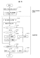
- the figure showing the waveform explaining the soft output decoding in a 1st Example The flowchart showing the likelihood update procedure in a 1st Example.
- the block diagram of the soft output decoding part in a 2nd Example The memory block diagram in a 2nd Example.
- the flowchart showing the likelihood update procedure in a 2nd Example The block diagram of the soft output decoding part in a 3rd Example.
- the present embodiment provides an information reproducing apparatus and method capable of outputting an appropriate reliability in the PRML (Partial Response Maximum Likelihood) method for optical disc reproduction.
- PRML Partial Response Maximum Likelihood
- the error correction encoding unit 102 performs error correction encoding using an LDPC (Low Density Parity Check) code
- the modulation unit 103 is used in, for example, BD ( 1, 7)
- a process of modulating 2-bit data into 3-bit data is executed according to the RLL modulation method.
- the (1, 7) RLL modulation method is modulated data in accordance with the run length restriction of RLL (1, 7) in which the number of consecutive 0s in the modulated bits is a minimum of 1 and a maximum of 7 ranges. Modulation method.
- An LDD (Laser Diode Driver) 104 performs laser intensity modulation necessary for recording modulation data on the disk, and a pickup 105 emits a laser and records it on the disk 106.
- LDD Laser Diode Driver
- the recorded data is read from the disk 106 via the pickup 105, the AFE (Analog Front End) 108 executes amplitude adjustment and filtering, and the ADC (Analog-Digital Converter) 109 performs digitization processing.
- the waveform equalizing unit 110 equalizes the digitized reproduction signal into a waveform so as to have PR characteristics such as PR (1, 2, 2, 2, 1) used in the soft output decoding unit 111, and outputs a soft output decoding unit. 111 obtains a soft output decoded value by a method described later.
- the soft value demodulator 112 demodulates the (1, 7) RLL modulation of the soft output decoded value, and the error correction unit 113 transmits the data to the host 101 after performing error correction of the LDPC code by sum-product decoding or the like. .
- the basis of the soft output decoding unit 111 is Viterbi decoding.
- BDXL uses a PR characteristic of PR (1, 2, 2, 2, 1), and (1, 7) RLL modulation as shown in FIG. Decoding is performed by state transition reflecting the above.
- the Euclidean distance ED (T, W) between the maximum likelihood waveform (T in FIG. 3) and the waveform equalization unit 110 output waveform (W in FIG. 3) in Viterbi decoding is (Equation 1), and the error waveform (F in FIG. 3).
- the Euclidean distance ED (F, W) of the waveform (W) output waveform (W) is expressed by (Expression 2), and the likelihood ⁇ that is the difference between them is expressed by (Expression 3).
- t n, f n, w n represents T at time n, F, the amplitude value of the W.
- Sum-product decoding in the error correction unit 113 is a log domain decoding method
- the reliability that is the output of the soft output decoding unit 111 needs to be a log likelihood ratio (LLR).
- This LLR can be approximated by (Equation 4) if the probability density function of the likelihood ⁇ is close to a normal distribution. ⁇ represents an average value of the distribution, and ⁇ represents a standard deviation.
- the decoded values of T and F become patterns that can actually exist, that is, the shortest run length is 2T and 1T exists.
- the decoded value of T is [000011]
- the decoded value of F is [0001111]
- the number of error bits is 1.
- the decoded value of T is [00011000]
- the decoded value of F is [00110000]
- the number of error bits is 2. This is because the Viterbi algorithm operates so as to satisfy the rules of RLL modulation, and if T in FIG. 5 is incorrect, 1T shift is not allowed and the 2T portion slips. For this reason, in RLL-modulated data, the Euclidean distance between T and F (formula 5) changes depending on the decoding result.
- FIG. 4 shows an image in which the likelihood ⁇ is histogrammed for the RLL-modulated data sequence with the horizontal axis representing the likelihood ⁇ and the vertical axis representing the occurrence frequency.
- the pattern distribution of FIG. 4 is a first distribution
- the present embodiment is characterized in that the likelihood ⁇ is normalized by the Euclidean distance between T and F as shown in (Expression 7).
- FIG. 7 shows an image in which the normalized likelihood ⁇ ′ is histogrammed with the normalized likelihood ⁇ ′ on the horizontal axis and the occurrence frequency on the vertical axis.
- the configuration of the soft output decoding unit 111 is shown in FIG.
- PR characteristic to be used is described as PR (1, 2, 2, 2, 1), it is not limited to this.
- the BM calculation unit 801 calculates a branch metric which is the square of the difference between the reference values REF00000 to REF11111 in FIG. 2 and the equalized waveform input to the soft output decoding unit 111. Thereafter, the ACS calculation unit 802 adds a branch metric to the path metric for each of the states S0000 to S1111 in FIG. 2, compares the addition results at the point where the paths in FIG. 2 merge, and selects a smaller path. The difference of the addition results of the two joined paths is stored in the likelihood candidate memory 803 as the likelihood candidate ⁇ . Further, the path selection result of the ACS calculation unit 802 is stored in the path memory 804.
- FIG. 9 shows the configurations of the path memory 804 and the likelihood candidate memory 803 when the path memory length for the prior maximum likelihood path determination is L1 and the path memory length for the maximum likelihood path determination is L2.
- the horizontal axis indicates time, and the time n is the base point.
- FIG. 9 also shows examples of a maximum likelihood decoded value memory 808, a competitive decoded value memory 809, and a likelihood memory 813, which will be described later.
- the path determination method will be described with reference to FIG.
- the trellis diagram of FIG. 10 is a development of the state transition diagram of FIG.
- the maximum likelihood path determination unit 805 determines the maximum likelihood path by tracing back the path selection result of the path memory 804 from time n + L1 to time n.
- the state at time n is set as a base state.
- the maximum likelihood path determination unit 806 determines the maximum likelihood path by tracing back as usual from the time n to the time n ⁇ L2 with the base state at the time n as the start point.
- the contention path determination unit 807 selects a path different from that stored in the path memory 804 only with respect to the transition to the time n-1, starting from the base point state at the time n, and then from the time n-1 to the time n. -Determine the contention path by tracing back to L2 as usual. However, if there is only one path connected to the base point state, the base point state is moved from time n to time n-1, and only the transition to time n-2 is stored in the path memory 804. Choose a different path. Similarly, it is assumed that the number of paths connected to the base state is traced back to one.
- the decoding result by the maximum likelihood path in the maximum likelihood path determination unit 806 is stored in the maximum likelihood decoding value memory 808, and the decoding result by the maximum likelihood path in the competition path determination unit 807 is stored in the competitive decoding value memory 809.
- FIG. 11 shows the maximum likelihood waveform and the competition waveform corresponding to the maximum likelihood path and the competition path in FIG.
- the inter-signal distance calculation unit 810 generates a maximum likelihood waveform and a competing waveform by convolving PR characteristics such as PR (1, 2, 2, 2, 1) with the maximum likelihood decoded value and the competitive decoded value, and inter-waveform Euclidean distance. Is calculated.
- the normalized likelihood candidate calculation unit 811 acquires the likelihood candidate ⁇ (n) at time n from the likelihood candidate memory 803 (S1201).
- the likelihood candidate ⁇ (n) is divided by the inter-waveform Euclidean distance output from the inter-signal distance calculation unit 810 to calculate a normalized likelihood candidate ⁇ (n) ′ (S1202).
- the likelihood updating unit 812 acquires the kth (1 ⁇ k ⁇ L2) maximum likelihood decoded value bm k from the maximum likelihood decoded value memory 808 (S1203), and the kth (1 ⁇ k ⁇ 1) from the competitive decoded value memory 809.
- the contention decoding value bc k of L2) is acquired (S1204).
- the maximum likelihood decoded value bm k and the competitive decoded value bc k are compared (S1205).
- k-th likelihood delta k stored in the likelihood memory 813 is held as it is (S1206).
- the comparison result shows non-coincidence, it compares the k-th likelihood stored in the likelihood memory 813 delta k and the normalized likelihood candidate delta a (n) '(S1207).
- Comparison result in S1207, replacing 'a k-th likelihood delta k which is stored in the likelihood memory 813 is smaller delta (n)' normalized likelihood candidate delta (n) in (S1208) (e.g., FIG. 10 ⁇ 5 ).
- k-th likelihood delta k the normalized likelihood candidate delta (n) 'is stored in the likelihood memory 813 is larger is held as it is (S1206) (e.g., delta 8 in FIG. 10).
- the LLR calculation unit 814 calculates the LLR according to the LLR calculation formula of (Expression 4). In addition, although the average value ⁇ and the standard deviation ⁇ in (Expression 4) may be actually measured, values set in advance may be used. Finally, the multiplication unit 815 outputs the result of multiplying the L2nd maximum likelihood decoded value of the maximum likelihood decoded value memory 808 by the LLR to the soft value demodulating unit 112 as the reliability.
- the Euclidean distance is used to calculate the inter-waveform distance, but it may be read as an absolute value.
- (1, 7) RLL has been described as an example, the present invention is not limited to this, and can be applied to any modulation scheme. The same applies to the following embodiments.
- FIG. 13 shows the configuration of the soft output decoding unit 111 in this embodiment.
- the parts of the likelihood updating unit 812 and the likelihood memory 813 in the first embodiment (FIG. 8) are replaced with a likelihood updating unit 1301, a comparison likelihood memory 1302, and an output likelihood memory 1303 in FIG.
- the configuration of the comparison likelihood memory 1302 and the output likelihood memory 1303 is shown in FIG.
- the operations up to S1205 are the same as those in the first embodiment. If the comparison results in S1205 match, the kth likelihoods ⁇ k and ⁇ k ′ stored in the comparison likelihood memory 1302 and the output likelihood memory 1303 are held as they are (S1501). If the comparison result shows non-coincidence, to compare the k-th likelihood stored in the comparison likelihood memory 1302 delta k and likelihood candidate ⁇ (n) (S1502).
- S1502 comparison result of replacing the k-th likelihood delta k of likelihood candidate delta (n) is stored if the comparison likelihood memory 1302 less likelihood candidate ⁇ (n) (S1503), a further output
- the kth likelihood ⁇ k ′ stored in the likelihood memory 1303 is replaced with a normalized likelihood candidate ⁇ (n) ′ (S1504). If the likelihood candidate ⁇ (n) is large as a result of the comparison in S1502, the kth likelihoods ⁇ k and ⁇ k ′ stored in the comparison likelihood memory 1302 and the output likelihood memory 1303 are retained as they are ( S1501).
- S1503 and S1504 replacement of likelihood
- S1503 and S1504 replacement of likelihood
- the likelihood update comparison can be performed before normalization, and the actual output can use the likelihood after normalization, thereby improving the correction capability in soft decision decoding. Is possible.
- FIG. 16 shows the configuration of the soft output decoding unit 111 in this embodiment.
- the likelihood updating unit 812 of the first embodiment (FIG. 8) is replaced with the likelihood updating unit 1601 in FIG. 16, and the inter-signal distance calculation unit 810 and the normalized likelihood candidate calculation unit 811 in FIG. 8 are deleted. .
- S1205 comparison result matches, k-th likelihood delta k stored in the likelihood memory 813 is held as it is (S1701). If the comparison result shows non-coincidence, it compares the k-th likelihood stored in the likelihood memory 813 delta k and likelihood candidate delta a (n) (S1702). S1702 comparison result of replacing the k-th likelihood delta k of likelihood candidate delta (n) is stored in the likelihood memory 813 is smaller likelihood candidate ⁇ (n) (S1703), the likelihood candidate delta ( n) is the k-th likelihood delta k stored in the likelihood memory 813 is larger is held as it is (S1701).
- an appropriate likelihood can be output even when a likelihood that is not normalized is used, and the correction capability in soft decision decoding can be improved.
- This embodiment is different from the embodiment 1-3 in the operation of the competitive path determination.
- the maximum likelihood path and the competitive path are determined, whereas in the present embodiment, the maximum likelihood path determination is not performed.
- FIG. 19 shows the configuration of the soft output decoding unit 111 in this embodiment.
- the parts of the maximum likelihood path determination unit 806 and the competitive path determination unit 807 in the first embodiment (FIG. 8) are replaced with a maximum likelihood path determination unit 1901 and a competitive path determination unit 1902 in FIG. 19, and the likelihood candidate memory 803 in FIG.
- the prior maximum likelihood path determination unit 805 is deleted.
- the trellis diagram of FIG. 20 is a development of the state transition diagram of FIG. First, a state with the smallest path metric at time n is set as a base state. Next, the maximum likelihood path determination unit 1901 establishes the maximum likelihood path by tracing back as usual from the time n to the time n ⁇ L2 with the base state at the time n as the start point.
- the contention path determination unit 1902 selects a path different from that stored in the path memory 804 only for the transition to time n ⁇ 1, starting from the base point state at time n, and then from time n ⁇ 1 to time n -Determine the contention path by tracing back to L2 as usual.
- the following method may be adopted for determining the competitive path.
- the trellis diagram of FIG. 21 is a development of the state transition diagram of FIG.
- Maximum likelihood path determination section 1901 determines the maximum likelihood path by tracing back from time n to time n ⁇ L2 as usual, starting from the state that is the minimum path metric at time n.
- the contention path determination unit 1902 establishes the contention path by tracing back from time n to time n ⁇ L2 as usual, starting from the state where the path metric at the time n is the second smallest path metric.
- the likelihood candidate ⁇ (n) is a difference between the minimum path metric and the next path metric as shown in FIG.
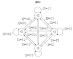
- FIG. 22 shows a state transition diagram of a two-dimensional PR characteristic of a 2 ⁇ 2 matrix as shown in (Equation 8).
- a, b, c, and d are arbitrary real numbers. Note that the two-dimensional PR characteristics to be used are not limited to this, and can be similarly extended by using an arbitrary matrix.
- the BM calculation unit 801 calculates a branch metric that is the square of the difference between the reference values REF [00; 00] to REF [11; 11] in FIG. 22 and the equalized waveform input to the soft output decoding unit 505. .
- the ACS calculation unit 802 adds the branch metric to the path metric for each of the states S [0; 0] to S [1; 1] in FIG. 22, and compares the addition results at the point where the paths in FIG. However, since the four paths merge as shown in the figure, the path with the smallest addition result is selected from the four paths.
- the trellis diagram of FIG. 23 is an expansion of the state transition diagram of FIG. 22 and considers the merging of paths at S [0; 0] of the nth pixel.
- the ACS calculation unit 802 calculates the addition result difference ( ⁇ 1 , ⁇ 2 , ⁇ 3 in FIG. 23) between the selected path and the other paths, and the smallest one of these ⁇ 1 , ⁇ 2 , ⁇ 3 is calculated. It is determined that the path is most likely to be erroneous, and is stored in the likelihood candidate memory 803 as a likelihood candidate ⁇ . Delta 1 in FIG. 23 is a minimum.
- the competitive path determination unit 807 selects a path different from that stored in the path memory 804 only for the transition to the (n-1) th pixel, starting from the base point state at the nth pixel. Is the path used when the likelihood candidate ⁇ is calculated.
- the A path in FIG. 23 delta 1 are competing paths.
- the likelihood updating unit 812 acquires the kth (1 ⁇ k ⁇ L2) maximum likelihood decoded value bm k from the maximum likelihood decoded value memory 808 (S1203), and the kth (1 ⁇ k) from the competitive decoded value memory 809. ⁇ L2) is obtained as a competitive decoded value bc k (S1204).
- the maximum likelihood decoded value bm k and the competitive decoded value bc k are 2-bit signals.
- the comparison is performed using the 0th bit and the 1st bit. Thereafter, the likelihood update is performed for each of the 0th bit and the 1st bit.
Landscapes
- Engineering & Computer Science (AREA)
- Signal Processing (AREA)
- Signal Processing For Digital Recording And Reproducing (AREA)
- Error Detection And Correction (AREA)
Abstract
情報再生装置において、RLL変調されているデータ列に対しても有効な信頼度を算出する方法を提供する。装置の構成は、最も確からしい復号結果となる最尤パスを出力する最尤パス判定部と、前記最尤パスと異なる復号結果となる競合パスを出力する競合パス判定部と、前記最尤パスと前記競合パスの差分である尤度を出力する尤度演算部と、前記最尤パスの復号結果から生成される最尤波形と、前記競合パスの復号結果から生成される競合波形との距離である信号間距離を出力する信号間距離演算部と、前記尤度を前記信号間距離で正規化した正規化尤度に基づいて信頼度を出力する信頼度出力部とを有する。
Description
本発明は、情報記録媒体から情報を再生する情報再生装置および情報再生方法に関する。
現在、光ディスクの容量を向上させるため、BD(Blu-ray Disc(商標))規格では1層25GBを2層、またBDXL(商標)規格では1層32GBを4層のように高密度化、多層化が図られている。
今後の更なる高密度、大容量化においては、例えば特許文献1の段落〔0007〕に記載の技術が挙げられる。この文献には、「その有力方式として、SOVA(Soft-Output Viterbi Algorithm)がある。これは、硬判定出力型PRML検出部210において、最尤復号されたバイナリデータ(0,1)に加え、その信頼度(復号結果の確からしさに関する情報)を出力し、アナログ値としての復号結果を得る方式である。書き込み側で予め符号化(外符号化)しておけば、読み出し側では前記アナログ値を用いて、外符号を軟判定復号することができる。軟判定復号は、アナログ値を信頼度情報として利用できるため、硬判定復号に比べて誤り率特性が向上することが知られている。」と記載されている。
このSOVAにおける信頼度を得るには、例えば特許文献1の段落〔0018〕に記載のように、「軟判定出力型PRML検出器において、最尤復号系列と同時に2番目に確からしい系列(2nd系列)を求め、両系列に対する尤度の差を求め、これを更新する手段を設ける」ことで可能にしていた。
しかし、光ディスクなどにこの技術を適用する場合、RLL(Run Length Limited)変調されている点が問題となる。RLL変調されることによって、最尤復号系列と2nd系列の距離がデータ列のパターンによって変化することになり、特許文献1のように「両系列に対する尤度の差」を求めるだけの方法では、正しく尤度を求めることはできない。
そこで本発明の目的は、RLL変調されているデータ列に対しても有効な信頼度を算出する情報再生装置および情報再生方法を提供することにある。
上記課題は、請求の範囲に記載の発明により解決される。その一例を挙げるなら、情報再生装置において、最も確からしい復号結果となる最尤パスを出力する最尤パス判定部と、前記最尤パスと異なる復号結果となる競合パスを出力する競合パス判定部と、前記最尤パスと前記競合パスの差分である尤度を出力する尤度演算部と、前記最尤パスの復号結果から生成される最尤波形と、前記競合パスの復号結果から生成される競合波形との距離である信号間距離を出力する信号間距離演算部と、前記尤度を前記信号間距離で正規化した正規化尤度に基づいて信頼度を出力する信頼度出力部と、を有する構成とする。
本発明によれば、RLL変調されているデータ列に対しても有効な信頼度を算出することが可能となり、軟判定復号における訂正能力を向上させる効果がある。
以下、本発明の実施例について説明する。
本実施例は、光ディスク再生におけるPRML(Partial Response Maximum Likelihood)方式において、適切な信頼度を出力することを可能とする情報再生装置および方法を提供する。
まず図1を用いて本実施例の記録再生装置および方法の概略について説明する。
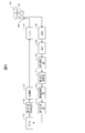
記録動作時には、ホスト101からユーザーデータを受信し、誤り訂正符号化部102はLDPC(Low Density Parity Check)符号などにより誤り訂正符号化を、変調部103は例えばBDで使用されているような(1、7)RLL変調方式に従い、2ビットデータを3ビットデータへ変調する処理を実行する。(1、7)RLL変調方式とは、変調後のビットにおいて連続する0の数が最小1つ、最大7個の範囲となるRLL(1,7)のランレングス制限に従った変調データとする変調方式である。LDD(Laser Diode Driver)104は変調データをディスクに記録するために必要なレーザーの強度変調を行い、ピックアップ105はレーザーを発光しディスク106に記録する。
次に再生動作時には、ディスク106よりピックアップ105を介して記録データを読み出し、AFE(Analog Front End)108は振幅調整とフィルター処理を実行し、ADC(Analog-Digital Converter)109はデジタル化処理する。波形等化部110はデジタル化された再生信号を軟出力復号部111で使用するPR(1,2,2,2,1)などのPR特性となるように波形に等化し、軟出力復号部111は後述する方法により軟出力復号値を得る。軟値復調部112は軟出力復号値の(1、7)RLL変調を復調し、誤り訂正部113はSum-product復号などによるLDPC符号の誤り訂正を実施した後、ホスト101にデータを送信する。
ここで、図2乃至図7を用いて軟出力復号部111の概念について説明する。
軟出力復号部111の基本はビタビ復号であり、例えばBDXLではPR(1,2,2,2,1)というPR特性を使用しており、図2に示すように(1、7)RLL変調を反映した状態遷移による復号を行う。ビタビ復号における最尤波形(図3のT)と波形等化部110出力波形(図3のW)のユークリッド距離ED(T,W)は(式1)で、誤り波形(図3のF)と波形等化部110出力波形(W)のユークリッド距離ED(F,W)は(式2)で、それらの差分である尤度Δは(式3)で表わされる。tn、fn、wnは時刻nにおけるT、F、Wの振幅値を示す。

また、誤り訂正部113におけるSum-product復号は対数領域の復号法であることから、軟出力復号部111出力である信頼度は対数尤度比(LLR:Log Likelihood Ration)とする必要がある。このLLRは、尤度Δの確率密度関数が正規分布に近いとすれば(式4)で近似することが可能である。μは分布の平均値、σは標準偏差を示す。

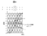
この信頼度算出の過程において、(1、7)RLL変調が施されたデータではT、Fの復号値は実際に存在し得るパターンとなること、すなわち最短ランレングスは2Tであり1Tの存在を許容しないという点が問題となる。例えば図4の例において、Tの復号値は[0000111]、Fの復号値は[0001111]であり誤りビット数は1であるが、図5の例において、Tの復号値は[00011000]、Fの復号値は[00110000]であり誤りビット数は2となる。これはRLL変調の規則を満たすようにビタビアルゴリズムが動作するため、図5のTが誤る場合1Tシフトは許容されず2T部分がスリップすることに起因する。このためRLL変調されたデータにおいて、TとFのユークリッド距離(式5)は復号結果によって変化してしまう。

この影響について図6を用いて説明する。図は横軸を尤度Δ、縦軸を発生頻度として、RLL変調されたデータ列に対して尤度Δをヒストグラム化したイメージを示す。図4のパターンの分布を第1分布、図5のパターンの分布を第2分布とした。それぞれの分布は正規分布に従うとすれば、分布の平均値μはW=Tとなる時であり(式6)で示される。

この値はTとFのユークリッド距離がパターンによって異なることから、第1分布と第2分布で異なり、結果として合成した全体分布は正規分布から外れる。このため(式4)に示したLLR計算式を適用することが困難となる。
そこでこの問題を解決するため、本実施例は(式7)に示すようにTとFのユークリッド距離で尤度Δを正規化することを特徴とする。

図7は横軸を正規化尤度Δ’、縦軸を発生頻度として正規化尤度Δ’をヒストグラム化したイメージを示す。正規化尤度を使用することにより平均値が一致し、全体分布も正規分布に近くなることからLLRを正しく算出することが可能となる。
以下にこの概念を用いた軟出力復号部111の詳細について、図8乃至図12を用いて説明する。まず図8に軟出力復号部111の構成を示す。なお、使用するPR特性をPR(1,2,2,2,1)として説明するがこれに限定するものではない。
まずBM演算部801において、図2の基準値REF00000~REF11111と軟出力復号部111の入力である等化波形との差分の2乗であるブランチメトリックを計算する。その後、ACS演算部802において図2のステートS0000~S1111毎のパスメトリックにブランチメトリックを加算し、図2のパスが合流している点で加算結果を比較し小さいパスを選択する。この合流した2つのパスの加算結果差分を尤度候補Δとして尤度候補メモリ803に格納する。また、ACS演算部802のパス選択結果をパスメモリ804に格納する。
尤度を算出する際に最尤パスが不確かであればその尤度の信頼性も落ちることから、最尤パスを確定させた後、その結果を基点として尤度算出用の最尤パスと競合パスを確定させる。この最初の最尤パス判定を事前最尤パス判定部805で、その結果を基点とする最尤パス判定を最尤パス判定部806で、競合パス判定を競合パス判定部807で実施する。事前最尤パス判定のパスメモリ長をL1、最尤パス判定のパスメモリ長をL2とした時の、パスメモリ804と尤度候補メモリ803の構成を図9に示す。横軸は時刻を示し、時刻nを基点としている。なお、図9には後述する最尤復号値メモリ808、競合復号値メモリ809、尤度メモリ813の例も示している。
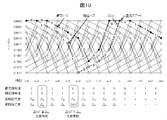
図10を用いてこのパス判定方法について時刻n周辺を例に説明する。図10のトレリス線図は図2の状態遷移図を展開したものである。まず、事前最尤パス判定部805において、パスメモリ804のパス選択結果を時刻n+L1から時刻nまでトレースバックすることにより最尤パスを確定する。この時刻nでのステートを基点ステートとする。次に最尤パス判定部806において、時刻nでの基点ステートを開始点として、時刻nから時刻n-L2まで通常通りトレースバックすることにより最尤パスを確定する。また競合パス判定部807において、時刻nでの基点ステートを開始点として、時刻n-1への遷移に関してのみパスメモリ804に格納されたのと異なるパスを選択、その後時刻n-1から時刻n-L2まで通常通りトレースバックすることにより競合パスを確定する。但し、基点となるステートに接続されるパスが1本だけだった場合、基点ステートを時刻nから時刻n-1に移し、時刻n-2への遷移に関してのみパスメモリ804に格納されたのと異なるパスを選択する。同様に基点となるステートに接続されるパスが1本でなくなるまで遡るものとする。最尤パス判定部806での最尤パスによる復号結果を最尤復号値メモリ808に、競合パス判定部807での最尤パスによる復号結果を競合復号値メモリ809に格納する。
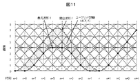
本実施例では前述のように最尤波形と競合波形のユークリッド距離で尤度を正規化する必要がある。図11に図10での最尤パスと競合パスに対応する最尤波形と競合波形を示す。信号間距離演算部810において最尤復号値と競合復号値にPR(1,2,2,2,1)といったPR特性を畳み込むなどして最尤波形と競合波形を生成し、波形間ユークリッド距離を算出する。
この後の尤度算出方法について図12のフローチャートを用いて説明する。
まず正規化尤度候補演算部811において、時刻nの尤度候補Δ(n)を尤度候補メモリ803から取得する(S1201)。この尤度候補Δ(n)を信号間距離演算部810出力である波形間ユークリッド距離で除算し、正規化尤度候補Δ(n)’を算出する(S1202)。尤度更新部812では、最尤復号値メモリ808からk番目(1≦k≦L2)の最尤復号値bmkを取得し(S1203)、競合復号値メモリ809からk番目(1≦k≦L2)の競合復号値bckを取得(S1204)する。そして最尤復号値bmkと競合復号値bckを比較する(S1205)。S1205での比較結果が一致したら、尤度メモリ813に格納されているk番目の尤度Δkはそのまま保持する(S1206)。比較結果が一致しなければ、尤度メモリ813に格納されているk番目の尤度Δkと正規化尤度候補Δ(n)’を比較する(S1207)。S1207での比較結果、正規化尤度候補Δ(n)’が小さければ尤度メモリ813に格納されているk番目の尤度ΔkをΔ(n)’に置き換える(S1208)(例えば図10のΔ5)。比較の結果、正規化尤度候補Δ(n)’が大きければ尤度メモリ813に格納されているk番目の尤度Δkはそのまま保持する(S1206)(例えば図10のΔ8)。これらS1203からS1208までの処理をk=1からL2まで実施し、その過程でS1208(尤度の置き換え)が実行されたかを確認する(S1209)。S1208が実行された場合は尤度メモリ813のL2番目の尤度ΔL2を尤度として出力し(S1210)、実行されなかった場合は尤度が一度も更新されなかったので尤度を1として出力する(S1211)。これは、正規化尤度を使用しているため図7に示す分布の平均値を与えていることに相当する。
以上で算出した尤度Δを用いて、LLR演算部814において、(式4)のLLR計算式に従いLLRを算出する。なお、(式4)における平均値μ、標準偏差σは実測してもよいが、予め設定しておいた値を使用してもよい。最後に乗算部815において、最尤復号値メモリ808のL2番目の最尤復号値とLLRを乗算した結果を信頼度として軟値復調部112に出力する。
以上の回路構成、処理手順によれば、RLL変調されているデータ列に対しても有効な信頼度を算出することが可能となり、軟判定復号における訂正能力を向上させることが可能となる。
なお、本実施例では波形間距離を算出するのにユークリッド距離を利用したが、絶対値に読み替えて実施してもよい。また(1、7)RLLを例に説明したが、これに限定するものではなく、任意の変調方式においても適用可能である。これらのことは以降の実施例についても同様である。
本実施例では実施例1と異なり、尤度の更新には正規化しない尤度を使用する。図13は本実施例における軟出力復号部111の構成を示す。実施例1(図8)の尤度更新部812と尤度メモリ813の部分を、図13では尤度更新部1301、比較用尤度メモリ1302、出力用尤度メモリ1303で置き換えている。比較用尤度メモリ1302と出力用尤度メモリ1303の構成を図14に示す。
ここで、図13における尤度更新部1301の動作について図15のフローチャートを用いて説明する。
S1205までの動作は実施例1と同一である。S1205の比較結果が一致したら、比較用尤度メモリ1302および出力用尤度メモリ1303に格納されているk番目の尤度Δk、Δk’はそのまま保持する(S1501)。比較結果が一致しなければ、比較用尤度メモリ1302に格納されているk番目の尤度Δkと尤度候補Δ(n)を比較する(S1502)。S1502の比較結果、尤度候補Δ(n)が小さければ比較用尤度メモリ1302に格納されているk番目の尤度Δkを尤度候補Δ(n)に置き換え(S1503)、さらに出力用尤度メモリ1303に格納されているk番目の尤度Δk’を正規化尤度候補Δ(n)’に置き換える(S1504)。またS1502の比較結果、尤度候補Δ(n)が大きければ比較用尤度メモリ1302および出力用尤度メモリ1303に格納されているk番目の尤度Δk、Δk’はそのまま保持する(S1501)。これらS1203からS1504までの処理をk=1からL2まで実施し、その過程でS1503、S1504(尤度の置き換え)が実行されたかを確認する(S1505)。S1503、S1504が実行された場合は、出力用尤度メモリ1303のL2番目の尤度ΔL2’を尤度として出力し(S1506)、実行されなかった場合は尤度が一度も更新されなかったので尤度を1として出力する(S1507)。これは、正規化尤度を使用しているため図7に示す分布の平均値を与えていることに相当する。
以上の回路構成、処理手順によれば、尤度更新の比較は正規化前、実際に出力するのは正規化後の尤度を使用することができ、軟判定復号における訂正能力を向上させることが可能となる。
本実施例では実施例1、2と異なり、尤度の更新および出力にも正規化しない尤度を使用する。図16は本実施例における軟出力復号部111の構成を示す。実施例1(図8)の尤度更新部812の部分を図16では尤度更新部1601で置き換え、図8の信号間距離演算部810、正規化尤度候補演算部811を削除している。
ここで、図16における尤度更新部1601の動作について図17のフローチャートを用いて説明する。
S1205までの動作は実施例1と同一である。S1205の比較結果が一致したら、尤度メモリ813に格納されているk番目の尤度Δkはそのまま保持する(S1701)。比較結果が一致しなければ、尤度メモリ813に格納されているk番目の尤度Δkと尤度候補Δ(n)を比較する(S1702)。S1702の比較結果、尤度候補Δ(n)が小さければ尤度メモリ813に格納されているk番目の尤度Δkを尤度候補Δ(n)に置き換え(S1703)、尤度候補Δ(n)が大きければ尤度メモリ813に格納されているk番目の尤度Δkはそのまま保持する(S1701)。これらS1203からS1703までの処理をk=1からL2まで実施し、その過程でS1703(尤度の置き換え)が実行されたかを確認する(S1704)。S1703が実行された場合は、尤度メモリ813のL2番目の尤度ΔL2を尤度として出力する(S1705)。実行されなかった場合は尤度が一度も更新されなかったので、最尤波形と競合波形の波形間ユークリッド距離ED(T,F)が最小となるものを尤度として出力する(S1706)。これは、正規化しない場合、尤度は図18のような分布をとるため、その分布の中で最も誤り易いパスの分布の平均値(図18ではμ2)を与えていることに相当する。また、S1706で出力する尤度としては、図18における全体分布の平均値(μall)を使用しても良い。
以上の回路構成、処理手順によれば、正規化しない尤度を用いる場合においても適切な尤度を出力させることができ、軟判定復号における訂正能力を向上させることが可能となる。
本実施例が実施例1-3と異なるのは、競合パス判定の動作である。実施例1では事前最尤パス判定を実施した後、最尤パス、競合パスを判定していたのに対し、本実施例では事前最尤パス判定しないことを特徴とする。
図19は本実施例における軟出力復号部111の構成を示す。実施例1(図8)の最尤パス判定部806、競合パス判定部807の部分を図19では最尤パス判定部1901、競合パス判定部1902で置き換え、図8の尤度候補メモリ803、事前最尤パス判定部805を削除している。
図20を用いてこのパス判定方法について時刻n周辺を例に説明する。図20のトレリス線図は図2の状態遷移図を展開したものである。まず、時刻nでのパスメトリックが最小のステートを基点ステートとする。次に最尤パス判定部1901において、時刻nでの基点ステートを開始点として、時刻nから時刻n-L2まで通常通りトレースバックすることにより最尤パスを確定する。また競合パス判定部1902において、時刻nでの基点ステートを開始点として、時刻n-1への遷移に関してのみパスメモリ804に格納されたのと異なるパスを選択、その後時刻n-1から時刻n-L2まで通常通りトレースバックすることにより競合パスを確定する。
もしくは、競合パスの判定に以下の方法を採用してもよい。
図21を用いてこのパス判定方法について時刻n周辺を例に説明する。図21のトレリス線図は図2の状態遷移図を展開したものである。最尤パス判定部1901において、時刻nでの最小パスメトリックとなるステートを開始点として、時刻nから時刻n-L2まで通常通りトレースバックすることにより最尤パスを確定する。また競合パス判定部1902において、時刻nでのパスメトリックが二番目に小さい次点パスメトリックとなるステートを開始点として、時刻nから時刻n-L2まで通常通りトレースバックすることにより競合パスを確定する。なお、この場合の尤度候補Δ(n)は図21に示すように最小パスメトリックと次点パスメトリックの差分とする。
以上の回路構成、処理手順によれば、RLL変調されているデータ列に対しても有効な信頼度を算出することが可能となり、さらにメモリ量を削減することが可能である。
また、本実施例は実施例1に対して説明したが、他の実施例についても同様に適用可能である。
以上の実施例では1次元について説明したが、本実施例では2次元の例について説明する。実施例1と異なるのは尤度候補Δの算出方法などである。
図22、図23を用いて尤度候補Δの算出方法についてn番目ピクセル周辺を例に説明する。図22に(式8)に示すような2×2行列の2次元PR特性の状態遷移図を示す。a,b,c,dは任意の実数である。なお、使用する2次元PR特性はこれに限定するものではなく任意の行列を用いても同様に拡張できる。

まずBM演算部801において、図22の基準値REF[00;00]~REF[11;11]と軟出力復号部505入力である等化波形との差分の2乗であるブランチメトリックを計算する。その後、ACS演算部802において図22のステートS[0;0]~S[1;1]毎のパスメトリックにブランチメトリックを加算し、図22のパスが合流している点で加算結果を比較するのだが、図のように4本のパスが合流していることから、この4本のうち加算結果が最も小さくなるパスを選択する。
図23のトレリス線図は図22の状態遷移図を展開したものであり、n番目ピクセルのS[0;0]でのパスの合流を例に考える。ACS演算部802において、選択したパスとその他のパスの加算結果差分(図23のΔ1、Δ2、Δ3)を算出し、これらΔ1、Δ2、Δ3のうち最小となるものを最も誤り易いパスと判断し、尤度候補Δとして尤度候補メモリ803に格納する。図23ではΔ1が最小としている。
また、競合パス判定部807では、n番目ピクセルでの基点ステートを開始点として、n-1番目ピクセルへの遷移に関してのみパスメモリ804に格納されたのと異なるパスを選択するが、この異なるパスとは尤度候補Δを算出した時に使用したパスとする。図23ではΔ1であったパスを競合パスとしている。
さらに尤度更新部812では、最尤復号値メモリ808からk番目(1≦k≦L2)の最尤復号値bmkを取得し(S1203)、競合復号値メモリ809からk番目(1≦k≦L2)の競合復号値bckを取得する(S1204)。(式8)の例では図22のように2ビット同時に復号されるため、最尤復号値bmkと競合復号値bckは2ビットの信号となる。よって、最尤復号値bmkと競合復号値bckを比較する際には(S1205)、0ビット目と1ビット目の夫々のビットで比較を実施する。以降、尤度の更新は0ビット目と1ビット目の夫々で実施する。
以上の回路構成、処理手順によれば、2次元PR特性を用いた場合にも有効な信頼度を算出することが可能となり、軟判定復号を用いることにより訂正能力を向上させることが可能となる。
また、本実施例は実施例1に対して説明したが、他の実施例についても同様に適用可能である。
101:ホスト、102:誤り訂正符号化部、103:変調部、104:LDD、105:ピックアップ、106:ディスク、107:スピンドルモータ、108:AFE、109:ADC、110:波形等化部、111:軟出力復号部、112:軟値復調部、113:誤り訂正部、801:BM演算部、802:ACS演算部、803:尤度候補メモリ、804:パスメモリ部、805:事前最尤パス判定部、806:最尤パス判定部、807:競合パス判定部、808:最尤復号値メモリ、809:競合復号値メモリ、810:信号間距離演算部、811:正規化尤度候補演算部、812:尤度更新部、813:尤度メモリ、814:LLR演算部、815:乗算部、1301:尤度更新部、1302:比較用尤度メモリ、1303:出力用尤度メモリ、1601:尤度更新部、1901:最尤パス判定部、1902:競合パス判定部。
Claims (14)
- 情報再生装置において、
最も確からしい復号結果となる最尤パスを出力する最尤パス判定部と、
前記最尤パスと異なる復号結果となる競合パスを出力する競合パス判定部と、
前記最尤パスと前記競合パスの差分である尤度を出力する尤度演算部と、
前記最尤パスの復号結果から生成される最尤波形と、前記競合パスの復号結果から生成される競合波形との距離である信号間距離を出力する信号間距離演算部と、
前記尤度を前記信号間距離で正規化した正規化尤度に基づいて信頼度を出力する信頼度出力部と、
を有することを特徴とする情報再生装置。 - 請求項1に記載の情報再生装置において、
前記尤度を前記信号間距離で正規化した正規化尤度を出力する正規化尤度演算部と、
前記最尤パスの復号結果と前記競合パスの復号結果が異なる時刻の尤度候補と前記正規化尤度を比較し、前記正規化尤度が小さい場合に前記正規化尤度を尤度候補とする尤度更新部と、
前記尤度候補に基づいて信頼度を出力する信頼度出力部と、
を有することを特徴とする情報再生装置。 - 請求項1に記載の情報再生装置において、
前記最尤パスの復号結果と前記競合パスの復号結果が異なる時刻の尤度候補と前記尤度を比較し、前記尤度が小さい場合に前記尤度を尤度候補とする尤度更新部と、
前記尤度候補を前記信号間距離で正規化した正規化尤度候補を出力する正規化尤度候補演算部と、
前記正規化尤度候補に基づいて信頼度を出力する信頼度出力部と、
を有することを特徴とする情報再生装置。 - 情報再生装置において、
最も確からしい復号結果となる最尤パスを出力する最尤パス判定部と、
前記最尤パスと異なる復号結果となる競合パスを出力する競合パス判定部と、
前記最尤パスと前記競合パスの差分である尤度を出力する尤度演算部と、
前記最尤パスの復号結果から生成される最尤波形と、前記競合パスの復号結果から生成される競合波形との距離である信号間距離を出力する信号間距離演算部と、
前記最尤パスの復号結果と前記競合パスの復号結果が異なる時刻の尤度候補と前記尤度を比較し、前記尤度が小さい場合に前記尤度を尤度候補とする尤度更新部と、
前記比較動作が実施されなかった場合は前記信号間距離に基づいて信頼度を出力し、前記比較動作が実施された場合は前記尤度候補に基づいて信頼度を出力する信頼度出力部と、
を有することを特徴とする情報再生装置。 - 請求項4に記載の情報再生装置において、
前記比較動作が実施されなかった場合は前記信号間距離の最小値に基づいて信頼度を出力し、前記比較動作が実施された場合は前記尤度候補に基づいて信頼度を出力する信頼度出力部を有することを特徴とする情報再生装置。 - 請求項4に記載の情報再生装置において、
前記比較動作が実施されなかった場合は前記信号間距離の平均値に基づいて信頼度を出力し、前記比較動作が実施された場合は前記尤度候補に基づいて信頼度を出力する信頼度出力部を有することを特徴とする情報再生装置。 - 請求項1乃至6に記載の情報再生装置において、
前記競合パスとは、前記最尤パスのある時刻のパス合流点において強制的に分岐させたパスとすることを特徴とする情報再生装置。 - 情報再生方法において、
最も確からしい復号結果となる最尤パスを出力し、
前記最尤パスと異なる復号結果となる競合パスを出力し、
前記最尤パスと前記競合パスの差分である尤度を出力し、
前記最尤パスの復号結果から生成される最尤波形と、前記競合パスの復号結果から生成される競合波形との距離である信号間距離を出力し、
前記尤度を前記信号間距離で正規化した正規化尤度に基づいて信頼度を出力することを特徴とする情報再生方法。 - 請求項8に記載の情報再生方法において、
前記尤度を前記信号間距離で正規化した正規化尤度を出力し、
前記最尤パスの復号結果と前記競合パスの復号結果が異なる時刻の尤度候補と前記正規化尤度を比較し、前記正規化尤度が小さい場合に前記正規化尤度を尤度候補とし、
前記尤度候補に基づいて信頼度を出力することを特徴とする情報再生方法。 - 請求項8に記載の情報再生方法において、
前記最尤パスの復号結果と前記競合パスの復号結果が異なる時刻の尤度候補と前記尤度を比較し、前記尤度が小さい場合に前記尤度を尤度候補とし、
前記尤度候補を前記信号間距離で正規化した正規化尤度候補を出力し、
前記正規化尤度候補に基づいて信頼度を出力することを特徴とする情報再生方法。 - 情報再生方法において、
最も確からしい復号結果となる最尤パスを出力し、
前記最尤パスと異なる復号結果となる競合パスを出力し、
前記最尤パスと前記競合パスの差分である尤度を出力し、
前記最尤パスの復号結果から生成される最尤波形と、前記競合パスの復号結果から生成される競合波形との距離である信号間距離を出力し、
前記最尤パスの復号結果と前記競合パスの復号結果が異なる時刻の尤度候補と前記尤度を比較し、前記尤度が小さい場合に前記尤度を尤度候補とし、
前記比較動作が実施されなかった場合は前記信号間距離に基づいて信頼度を出力し、前記比較動作が実施された場合は前記尤度候補に基づいて信頼度を出力することを特徴とする情報再生方法。 - 請求項11に記載の情報再生方法において、
前記比較動作が実施されなかった場合は前記信号間距離の最小値に基づいて信頼度を出力し、前記比較動作が実施された場合は前記尤度候補に基づいて信頼度を出力することを特徴とする情報再生方法。 - 請求項11に記載の情報再生方法において、
前記比較動作が実施されなかった場合は前記信号間距離の平均値に基づいて信頼度を出力し、前記比較動作が実施された場合は前記尤度候補に基づいて信頼度を出力することを特徴とする情報再生方法。 - 請求項8乃至13に記載の情報再生方法において、
前記競合パスとは、前記最尤パスのある時刻のパス合流点において強制的に分岐させた
パスとすることを特徴とする情報再生方法。
Applications Claiming Priority (2)
| Application Number | Priority Date | Filing Date | Title |
|---|---|---|---|
| JP2011-090630 | 2011-04-15 | ||
| JP2011090630A JP2012226788A (ja) | 2011-04-15 | 2011-04-15 | 情報再生装置および情報再生方法 |
Publications (1)
| Publication Number | Publication Date |
|---|---|
| WO2012140997A1 true WO2012140997A1 (ja) | 2012-10-18 |
Family
ID=47009179
Family Applications (1)
| Application Number | Title | Priority Date | Filing Date |
|---|---|---|---|
| PCT/JP2012/057552 Ceased WO2012140997A1 (ja) | 2011-04-15 | 2012-03-23 | 情報再生装置および情報再生方法 |
Country Status (2)
| Country | Link |
|---|---|
| JP (1) | JP2012226788A (ja) |
| WO (1) | WO2012140997A1 (ja) |
Families Citing this family (1)
| Publication number | Priority date | Publication date | Assignee | Title |
|---|---|---|---|---|
| CN104571795B (zh) * | 2013-10-28 | 2018-08-31 | 联想(北京)有限公司 | 一种信息处理方法及电子设备 |
Citations (3)
| Publication number | Priority date | Publication date | Assignee | Title |
|---|---|---|---|---|
| JPH11355151A (ja) * | 1998-06-11 | 1999-12-24 | Hitachi Ltd | ビタビ検出器及びこれを用いたディジタル磁気記録再生装置 |
| JP2005166221A (ja) * | 2003-12-05 | 2005-06-23 | Canon Inc | 情報再生方法及び情報再生装置 |
| JP2006286073A (ja) * | 2005-03-31 | 2006-10-19 | Sony Corp | 最尤復号装置、信号評価方法、再生装置 |
Family Cites Families (3)
| Publication number | Priority date | Publication date | Assignee | Title |
|---|---|---|---|---|
| JP4652310B2 (ja) * | 2006-10-31 | 2011-03-16 | 富士通株式会社 | 復号器及び再生装置 |
| JP4885799B2 (ja) * | 2007-06-05 | 2012-02-29 | シャープ株式会社 | 信号評価装置、信号評価方法、信号評価プログラム、およびコンピュータ読み取り可能な記録媒体 |
| JP2010140551A (ja) * | 2008-12-11 | 2010-06-24 | Panasonic Corp | 光ディスク再生方法および再生装置 |
-
2011
- 2011-04-15 JP JP2011090630A patent/JP2012226788A/ja active Pending
-
2012
- 2012-03-23 WO PCT/JP2012/057552 patent/WO2012140997A1/ja not_active Ceased
Patent Citations (3)
| Publication number | Priority date | Publication date | Assignee | Title |
|---|---|---|---|---|
| JPH11355151A (ja) * | 1998-06-11 | 1999-12-24 | Hitachi Ltd | ビタビ検出器及びこれを用いたディジタル磁気記録再生装置 |
| JP2005166221A (ja) * | 2003-12-05 | 2005-06-23 | Canon Inc | 情報再生方法及び情報再生装置 |
| JP2006286073A (ja) * | 2005-03-31 | 2006-10-19 | Sony Corp | 最尤復号装置、信号評価方法、再生装置 |
Also Published As
| Publication number | Publication date |
|---|---|
| JP2012226788A (ja) | 2012-11-15 |
Similar Documents
| Publication | Publication Date | Title |
|---|---|---|
| JP4313755B2 (ja) | 再生信号の評価方法および光ディスク装置 | |
| US7940622B2 (en) | Recording/reproduction device, evaluation value calculation method, and evaluation value calculation device | |
| US20070061687A1 (en) | Soft decoding method and apparatus, error correction method and apparatus, and soft output method and apparatus | |
| JP4622632B2 (ja) | 最尤復号装置、信号評価方法、再生装置 | |
| CN103548084B (zh) | 光信息再现装置和光信息再现方法 | |
| JPWO2010001588A1 (ja) | 再生信号評価方法、再生信号評価装置及びこれを備えた光ディスク装置 | |
| US7110199B2 (en) | Information recording and reproducing apparatus, signal decoding circuit, and information recording medium and method | |
| JP2004253114A (ja) | 信号評価方法と情報記録再生装置と情報再生装置及び情報記録媒体 | |
| US20100095190A1 (en) | Storage device and data reading method thereof | |
| RU2505869C2 (ru) | Способ оценки сигнала воспроизведения, блок оценки сигнала воспроизведения и устройство на оптическом диске, оснащенное таким блоком оценки сигнала воспроизведения | |
| JP2014027432A (ja) | 復号装置、記憶装置、および復号方法 | |
| JP3711140B2 (ja) | 情報記録再生装置及びその信号評価方法 | |
| US7006019B2 (en) | Rate-7/8 maximum transition run code encoding and decoding method and apparatus | |
| US7660224B2 (en) | DC-controlled encoding for optical storage system | |
| JP2012226788A (ja) | 情報再生装置および情報再生方法 | |
| JP4161487B2 (ja) | データ復号装置及び方法 | |
| US9461672B2 (en) | Signal quality evaluation apparatus, signal quality evaluation method, and reproducing device | |
| JP3539091B2 (ja) | データ復号方法及びデータ復号装置 | |
| JP2006269045A (ja) | 信号品質評価装置、情報記録再生装置、信号品質評価方法、記録条件決定方法、信号品質評価プログラム、信号品質評価プログラムを記録したコンピュータ読み取り可能な記録媒体 | |
| KR20050072428A (ko) | 비트 검출방법 및 장치 | |
| JP4983032B2 (ja) | 復調テーブル、復調装置および方法、プログラム、並びに記録媒体 | |
| JP3756927B2 (ja) | 情報記録再生装置及びその信号評価方法 | |
| US20100322052A1 (en) | Reproduction signal quality evaluation device and method | |
| US20080104490A1 (en) | Digital data decoding apparatus and digital data decoding method | |
| JP2003520383A (ja) | アナログ信号を二進出力信号に変換する方法 |
Legal Events
| Date | Code | Title | Description |
|---|---|---|---|
| 121 | Ep: the epo has been informed by wipo that ep was designated in this application |
Ref document number: 12770936 Country of ref document: EP Kind code of ref document: A1 |
|
| NENP | Non-entry into the national phase |
Ref country code: DE |
|
| 122 | Ep: pct application non-entry in european phase |
Ref document number: 12770936 Country of ref document: EP Kind code of ref document: A1 |