WO2012140778A1 - 手動変速機のシフト荷重制御装置 - Google Patents
手動変速機のシフト荷重制御装置 Download PDFInfo
- Publication number
- WO2012140778A1 WO2012140778A1 PCT/JP2011/059423 JP2011059423W WO2012140778A1 WO 2012140778 A1 WO2012140778 A1 WO 2012140778A1 JP 2011059423 W JP2011059423 W JP 2011059423W WO 2012140778 A1 WO2012140778 A1 WO 2012140778A1
- Authority
- WO
- WIPO (PCT)
- Prior art keywords
- shift
- speed
- gear
- manual transmission
- shaft
- Prior art date
- Legal status (The legal status is an assumption and is not a legal conclusion. Google has not performed a legal analysis and makes no representation as to the accuracy of the status listed.)
- Ceased
Links
Images




Classifications
-
- F—MECHANICAL ENGINEERING; LIGHTING; HEATING; WEAPONS; BLASTING
- F16—ENGINEERING ELEMENTS AND UNITS; GENERAL MEASURES FOR PRODUCING AND MAINTAINING EFFECTIVE FUNCTIONING OF MACHINES OR INSTALLATIONS; THERMAL INSULATION IN GENERAL
- F16H—GEARING
- F16H61/00—Control functions within control units of change-speed- or reversing-gearings for conveying rotary motion ; Control of exclusively fluid gearing, friction gearing, gearings with endless flexible members or other particular types of gearing
- F16H61/18—Preventing unintentional or unsafe shift, e.g. preventing manual shift from highest gear to reverse gear
-
- F—MECHANICAL ENGINEERING; LIGHTING; HEATING; WEAPONS; BLASTING
- F16—ENGINEERING ELEMENTS AND UNITS; GENERAL MEASURES FOR PRODUCING AND MAINTAINING EFFECTIVE FUNCTIONING OF MACHINES OR INSTALLATIONS; THERMAL INSULATION IN GENERAL
- F16H—GEARING
- F16H63/00—Control outputs from the control unit to change-speed- or reversing-gearings for conveying rotary motion or to other devices than the final output mechanism
- F16H63/02—Final output mechanisms therefor; Actuating means for the final output mechanisms
- F16H63/30—Constructional features of the final output mechanisms
- F16H63/38—Detents
-
- F—MECHANICAL ENGINEERING; LIGHTING; HEATING; WEAPONS; BLASTING
- F16—ENGINEERING ELEMENTS AND UNITS; GENERAL MEASURES FOR PRODUCING AND MAINTAINING EFFECTIVE FUNCTIONING OF MACHINES OR INSTALLATIONS; THERMAL INSULATION IN GENERAL
- F16H—GEARING
- F16H61/00—Control functions within control units of change-speed- or reversing-gearings for conveying rotary motion ; Control of exclusively fluid gearing, friction gearing, gearings with endless flexible members or other particular types of gearing
- F16H61/24—Providing feel, e.g. to enable selection
- F16H2061/245—Ramp contours for generating force threshold, e.g. cams or pushers for generating additional resistance for a reverse path
Definitions
- the present invention relates to a shift load control device for a manual transmission mounted on an automobile or the like.
- the present invention relates to a measure for optimizing a shift load according to a driver's shift operation.
- a gear position is selected by operating a shift lever by a driver (driver).
- a shift lever is movably disposed in a shift gate formed with a gate groove extending in a direction (sometimes referred to as a shift operation direction). Then, after a select operation that operates the shift lever in the select operation direction along the gate groove, a desired gear position is established in the transmission mechanism of the manual transmission by performing a shift operation that operates in one direction of the shift operation direction.
- the manual transmission has a feature that a shift operation to an arbitrary gear stage intended by the driver is possible. That is, it can be said that the manual transmission has a great feature that the degree of freedom in selecting the shift speed is high (the selection of the shift speed depends on the driver's intention).
- JP 2009-103268 A JP-A-8-312687 JP-A-9-42441
- misshift when the driver operates the shift lever to switch the shift stage of the transmission mechanism, if the shift operation is incorrect and the driver switches to a shift stage not intended by the driver (hereinafter, this erroneous operation is referred to as a misshift), the clutch It may adversely affect the equipment and engine. In addition, drivability may be deteriorated.
- misshift for example, when an upshift is attempted from the second gear to the third gear, a shift operation to the first gear is erroneously performed. If such a misshift occurs, an excessive deceleration torque may be input to the clutch device when the clutch is engaged, or the engine speed may rise rapidly and exceed the allowable speed. Along with this, a shift shock to the deceleration side occurs and drivability deteriorates.
- Patent Document 2 and Patent Document 3 when the engine speed is expected to exceed the allowable engine speed by a gear shift operation, the gear shift operation is prohibited. Yes.
- the present invention has been made in view of such points, and the object of the present invention is to avoid adverse effects on the clutch device and the engine in a situation where an appropriate shift operation such as a misshift is not performed.
- An object of the present invention is to provide a shift load control device for a manual transmission.
- the solution principle of the present invention taken in order to achieve the above object is that the adverse effect on the clutch device and the engine is predicted when the gear is shifted to a predetermined low speed side (a gear stage side with a large gear ratio). Then, when the shift load to the low speed stage is increased and the shift operation to the low speed stage is performed, the driver is prompted to interrupt the shift operation, or the shift operation is delayed. By doing so, it is possible to avoid the adverse effects described above.
- the present invention is directed to a shift load control device for a manual transmission in which any one of a plurality of shift stages can be selected by a manual shift operation by a driver.
- the rotation speed of the output shaft of the manual transmission or the rotation speed downstream of the output shaft in the power transmission direction is set as the detection target rotation speed, and the detection target rotation speed Is greater than a predetermined rotation speed threshold value, the shift load at the time of manual shift operation to a predetermined low gear by the driver is set larger than when the detection target rotation speed is less than the rotation speed threshold value.
- Shift load adjusting means is provided.
- the manual transmission is mounted on a vehicle, and the rotation speed to be detected is the rotation speed of a driving wheel of the vehicle. That is, the shift load is increased when the vehicle speed is equal to or higher than the predetermined vehicle speed when the driver performs a manual shift operation to a predetermined low gear (for example, the first gear).
- a predetermined low gear for example, the first gear
- the shift load is increased by the shift load adjusting means only when an operation is performed.
- the rotational speed of the output shaft of the manual transmission or the rotational speed downstream of the output shaft in the power transmission direction is equal to or higher than a predetermined rotational speed threshold value.
- the shift load is increased during a manual shift operation to a predetermined low gear (for example, the first gear).
- the shift load is increased when a situation occurs in which the rotational speed of the input shaft of the manual transmission becomes excessively high as the shift speed is established.
- the driver needs a shift operation force larger than a normal shift operation force in order to establish the predetermined low shift stage.
- the specific configuration of the shift load adjusting means includes the following. That is, an inclined surface is provided on the outer peripheral surface of the shaft member to which the operating force of the manual shift operation by the driver is transmitted, and when the manual shift operation to the predetermined low gear is performed, the outer peripheral surface of the shaft member The pressing member is brought into contact with the inclined surface formed at the same time, and when the rotation speed to be detected is equal to or higher than a predetermined rotation speed threshold, the pressing force of the pressing member against the inclined surface is increased. It is configured.
- the fork shaft for establishing the first speed stage and the second speed stage, and for establishing the other speed stages
- At least one fork shaft is provided, and when the fork shaft moves to the first speed stage establishment side on the outer peripheral surface of the fork shaft for establishing the first speed stage and the second speed stage, a pressing member is applied.
- the inclined surface is provided at the contact position.
- Specific examples of the configuration for increasing the pressing force on the inclined surface by the pressing member include adjustment of hydraulic pressure applied to the back surface of the pressing member, and adjustment of pressing force by an electromagnetic solenoid.
- FIG. 1 is a sectional view showing a gear layout of the manual transmission according to the embodiment.
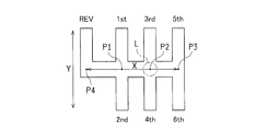
- FIG. 2 is a diagram schematically showing a shift pattern of the 6-speed manual transmission.
- FIG. 3 is a cross-sectional view of each forward-stage engaging portion and its peripheral portion in the select / shift mechanism as viewed from the axial direction of the shift select shaft.
- FIG. 4 is a cross-sectional view showing an engagement portion between the 5th-6th fork shaft and the third synchromesh mechanism.
- FIG. 5 is a cross-sectional view of each shift fork and its periphery as viewed from the axial direction of the shift select shaft.
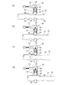
- FIG. 6 shows the operation of the fork shaft for 1st to 2nd gears and the shift load adjusting mechanism at a low vehicle speed, FIG.
- FIG. 6 (a) shows a neutral state
- FIG. 6 (b) shows a state where the first gear is established
- FIG. 6C is a diagram showing the second speed stage establishment state.
- FIG. 7 shows the operation of the 1st to 2nd fork shaft and the shift load adjusting mechanism at a high vehicle speed
- FIG. 7 (a) shows the second speed established state
- FIG. 7 (b) shows the neutral state
- FIG. 7C shows a state in the middle of the transition from the neutral state to the first gear stage established state
- FIG. 7D shows the first gear stage established state.
- FIG. 1 is a side view showing a part of a gear layout of a manual transmission according to the present embodiment in cross section.
- the gear layout shown in FIG. 1 is housed in a transmission case (not shown in FIG. 1), and is arranged in parallel with each other, an input shaft 1, an output shaft 2, and a reverse shaft 3 (in FIG. 1, a two-dot chain line). ) Is rotatably supported by the transmission case.
- the input shaft 1 is connected to a crankshaft of an engine (drive source) via a clutch mechanism (both not shown), and the rotational driving force of the engine is input by the joint operation of the clutch mechanism. ing.
- a plurality of transmission gear trains 4 to 10 are provided for establishing each of the first forward speed to the sixth forward speed and the reverse speed.
- the first speed gear train 4 the second speed gear train 5, the third speed gear train 6, the fourth speed gear train 7, 5
- a speed gear train 8 and a 6th gear train 9 are arranged in order.
- a reverse gear train 10 is provided as a reverse gear train.
- the first-speed gear train 4 includes a first-speed drive gear 4a attached to the input shaft 1 so as to rotate integrally (relatively impossible), and a first-speed driven gear 4b assembled to the output shaft 2 so as to be rotatable relative to the output shaft 2.
- the first speed drive gear 4a and the first speed driven gear 4b are meshed with each other.
- the second-speed gear train 5 includes a second-speed drive gear 5a that is attached to the input shaft 1 so as to rotate together, and a second-speed driven gear 5b that is assembled so as to be rotatable relative to the output shaft 2.
- the drive gear 5a and the second speed driven gear 5b mesh with each other.
- the third speed gear train 6 includes a third speed drive gear 6a that is assembled to the input shaft 1 so as to be rotatable relative to the input shaft 1, and a third speed driven gear 6b that is attached to the output shaft 2 so as to rotate together. 6a and the 3rd speed driven gear 6b mesh with each other.
- the 4-speed gear train 7 includes a 4-speed drive gear 7a that is assembled to the input shaft 1 so as to be relatively rotatable, and a 4-speed driven gear 7b that is attached to the output shaft 2 so as to rotate together. 7a and the 4-speed driven gear 7b mesh with each other.
- the 5-speed gear train 8 includes a 5-speed drive gear 8a that is assembled to the input shaft 1 so as to be rotatable relative to the input shaft 1, and a 5-speed driven gear 8b that is rotatably integrated with the output shaft 2. 8a and the fifth speed driven gear 8b mesh with each other.
- the 6-speed gear train 9 includes a 6-speed drive gear 9a assembled to the input shaft 1 so as to be relatively rotatable, and a 6-speed driven gear 9b attached to the output shaft 2 so as to rotate together. 9a and 6-speed driven gear 9b mesh with each other.
- the switching operation (transmission operation) of each transmission gear train is performed by the three synchromesh mechanisms (synchronizers) 11, 12, and 13.
- the first synchromesh mechanism 11 is provided on the output shaft 2 between the first speed driven gear 4b and the second speed driven gear 5b. That is, when the first synchromesh mechanism 11 is operated toward the first-speed driven gear 4b, the first-speed driven gear 4b is integrally connected to the output shaft 2 so as to be connected between the first-speed drive gear 4a and the first-speed driven gear 4b. Then, power is transmitted from the input shaft 1 to the output shaft 2 (establishment of the first speed stage).
- the second synchromesh mechanism 12 is provided on the input shaft 1 between the third speed drive gear 6a and the fourth speed drive gear 7a.
- the third speed drive gear 6a is integrally connected to the input shaft 1 to rotate between the third speed drive gear 6a and the third speed driven gear 6b.
- power transmission from the input shaft 1 to the output shaft 2 is performed (establishment of the third speed stage).
- the second synchromesh mechanism 12 is operated toward the 4th-speed drive gear 7a, the 4th-speed drive gear 7a is connected to the input shaft 1 so as to rotate together, and between the 4-speed drive gear 7a and the 4th-speed driven gear 7b.
- power transmission from the input shaft 1 to the output shaft 2 is performed (establishment of the fourth speed stage).
- the third synchromesh mechanism 13 is provided on the input shaft 1 between the fifth speed drive gear 8a and the sixth speed drive gear 9a.
- the fifth speed drive gear 8a is integrally connected to the input shaft 1 so that the fifth speed drive gear 8a and the fifth speed driven gear 8b are connected.
- power transmission from the input shaft 1 to the output shaft 2 is performed (establishment of the fifth speed stage).
- the third synchromesh mechanism 13 is operated to the 6-speed drive gear 9a side, the 6-speed drive gear 9a is connected to the input shaft 1 in a rotationally integrated manner, and between the 6-speed drive gear 9a and the 6-speed driven gear 9b.
- power transmission from the input shaft 1 to the output shaft 2 is performed (establishment of the sixth gear).
- the rotational driving force of the input shaft 1 is selected by the operation of any one of the above-described synchromesh mechanisms 11, 12, 13 except during the shift change operation. It is transmitted to the output shaft 2 via one transmission gear train 4-9.
- the reverse gear train 10 is slidably movable with respect to the reverse shaft 3, a reverse drive gear 10 a rotatably attached to the input shaft 1, a reverse driven gear 10 b rotatably attached to the output shaft 2, and the reverse shaft 3. And a reverse idler gear 10c (indicated by a two-dot chain line in FIG. 1).
- gears 10a, 10b, and 10c do not transmit power when the vehicle is moving forward, and when the vehicle is moving backward, all the synchromesh mechanisms 11, 12, and 13 are set to the neutral state, and the reverse idler gear 10c is connected to the reverse shaft 3 ,
- the reverse drive gear 10a meshes with both the reverse drive gear 10a and the reverse driven gear 10b, so that the rotation direction of the reverse drive gear 10a is reversed and transmitted to the reverse driven gear 10b.
- the output shaft 2 rotates in the opposite direction to that in the forward stage, and the drive wheels rotate in the reverse direction.
- the reverse driven gear 10b is disposed integrally with the outer periphery of the first synchromesh mechanism 11.
- the rotational driving force that is shifted or reversely rotated at a predetermined gear ratio and transmitted to the output shaft 2 is decelerated by the final reduction gear ratio of the final reduction gear train 15 including the final drive gear 15a and the final driven gear 15b. Then, it is transmitted to the differential device 16. As a result, the drive wheels (not shown) rotate in the forward or reverse direction.
- FIG. 2 schematically shows a shift pattern (shift gate shape) of the 6-speed manual transmission according to this embodiment.
- a shift lever L indicated by a two-dot chain line in the figure is configured in a shape that can be selected by a selection operation in the direction indicated by an arrow X in FIG. 2 and a shift operation in a direction indicated by an arrow Y orthogonal to the selection operation direction. .
- the 1st-2nd speed select position P1, the 3rd-4th speed select position P2, the 5th-6th speed select position P3 and the reverse (reverse) select position P4 are arranged in a line.
- the shift lever L can be moved to the first speed position 1st or the second speed position 2nd by the shift operation (operation in the arrow Y direction) at the first speed-2 speed select position P1.
- the first synchromesh mechanism 11 When the shift lever L is operated to the first speed position 1st, the first synchromesh mechanism 11 is operated to the first speed driven gear 4b side, and the first speed driven gear 4b is connected to the output shaft 2 in an integrated manner.
- the shift lever L is operated to the 2nd speed position 2nd, the first synchromesh mechanism 11 operates on the 2nd speed driven gear 5b side, and this 2nd speed driven gear 5b is connected to the output shaft 2 in an integrated manner.
- the shift lever L can be moved to the third gear position 3rd or the fourth gear position 4th by a shift operation at the third gear-4th gear select position P2.
- the second synchromesh mechanism 12 operates to the 3rd speed drive gear 6a side, and this 3rd speed drive gear 6a is connected to the input shaft 1 in an integrated manner.
- the second synchromesh mechanism 12 operates to the 4th speed drive gear 7a side, and this 4th speed drive gear 7a is connected to the input shaft 1 in an integrated manner. Is done.
- the shift lever L can be moved to the fifth speed position 5th or the sixth speed position 6th by a shift operation at the fifth speed-6th speed select position P3.
- the third synchromesh mechanism 13 operates toward the fifth speed drive gear 8a, and this fifth speed drive gear 8a is connected to the input shaft 1 in an integrated manner.
- the shift lever L is operated to the 6th speed position 6th
- the third synchromesh mechanism 13 is operated to the 6th speed drive gear 9a side, and this 6th speed drive gear 9a is connected to the input shaft 1 in an integrated manner. Is done.
- the shift lever L can be moved to the reverse position REV by a shift operation at the reverse select position P4.
- the shift lever L When the shift lever L is operated to the reverse position REV, all the synchromesh mechanisms 11, 12, 13 are in a neutral state, and the reverse idler gear 10c is moved along the axial direction of the reverse shaft 3 to It meshes with the reverse drive gear 10a and the reverse driven gear 10b.
- FIG. 3 is a cross-sectional view of the forward-stage engaging portions 22, 23, 24 and their peripheral portions in the select / shift mechanism as viewed from the axial direction of the shift select shaft 20.
- reference numeral 22 denotes a first-speed / second-speed forward gear engaging portion provided on the first-speed / second-speed fork shaft 51
- reference numeral 23 denotes a third-speed / four-speed fork shaft 52.
- a forward speed engaging portion for 3rd to 4th speed provided, and a reference numeral 24 is a forward speed engaging portion for 5th to 6th speed provided on the fork shaft 53 for 5th to 6th speed.
- FIG. 4 is a cross-sectional view showing an engagement portion between the 5th-6th fork shaft 53 and the third synchromesh mechanism 13.
- FIG. 5 is a cross-sectional view of the shift forks 31, 32, 33 provided on the fork shafts 51, 52, 53 and their peripheral parts when viewed from the axial direction of the shift select shaft 20.
- the shift lever L is connected to the shift select shaft 20 (see FIGS. 3 and 5) by a select cable and a shift cable (not shown) so as to be able to transmit operating force. Yes.
- the shift select shaft 20 rotates around the axis (in the direction indicated by the arrow M in FIGS. 3 and 5) according to the select operation of the shift lever L, and the axial direction ( 3 and 5 in the direction perpendicular to the paper surface).
- the select operation force for the shift lever L (the operation force in the direction indicated by the arrow X in FIG.
- shift forks 33 (in FIG. 4, three shift forks 31, 32) are provided corresponding to the sleeves 13a (see FIG. 4) provided in the synchromesh mechanisms 11, 12, 13 respectively. , 33, only the shift forks 33 for 5th to 6th are shown), and the base end portions of these shift forks 33 are fork for forward gears provided corresponding to each of them.
- the shafts 53 are respectively supported by the shafts 53 (only the fork shafts 53 for the 5th to 6th speeds of the three fork shafts 51, 52, 53 are shown).
- the fork shaft 53 (51, 52) is selected so that the shift operation force can be transmitted by the rotation of the shift select shaft 20 around the axis in accordance with the select operation of the shift lever L, and the shift lever L shifts.
- the selected fork shaft 53 (51, 52) slides in the axial direction, and one fork shaft 53 (51, 52) is provided.
- a predetermined one synchromesh mechanism 13 (11, 12) is operated via the shift fork 33 (31, 32).
- the shift inner lever 21 for selecting one fork shaft 52 includes a cylindrical portion (base) 21 a that is externally fitted and fixed to the outer periphery of the shift select shaft 20, and this And an arm portion 21b extending in the radial direction from the tube portion 21a. Further, an engagement pin P is inserted from the shift select shaft 20 to the cylindrical portion 21a, and the shift inner lever 21 is connected to the shift select shaft 20 in an integral manner and in a slidable manner.
- An interlock plate (interlock member) 26 is externally fitted to the cylindrical portion 21a of the shift inner lever 21 so as to be relatively movable in the axial direction and not to be rotatable around the axial line.
- the interlock plate 26 is formed with an engagement piece passage 26c formed of a pair of opposing guide surfaces slidably in contact with both sides of the arm portion 21b of the shift inner lever 21 extending in the axial direction. .
- the spacing between the guide surfaces of the engagement piece passage 26c restricts the passage of a plurality of heads 22a, 23a, 24a that are engaged with the arm portion 21b of the shift inner lever 21 and moved in the axial direction at the same time. In other words, only the passage of one head 23a (22a, 24a) is allowed.
- the interlock plate 26 is movable in the axial direction relative to the cylindrical portion 21a of the shift inner lever 21, but is provided so as not to move in the axial direction with respect to the transmission case. .
- FIG. 3 shows the rotational positions of the shift select shaft 20 and the shift inner lever 21 when the shift lever L is operated to the 3rd speed-4th speed select position P2.
- the fork shafts 51, 52, 53 (corresponding to the synchromesh mechanisms 11, 12, 13) (in FIGS. 1 and 3, fork shaft 51 for 1st to 2nd speeds, 3rd speed to 4th speeds)
- Fork shaft 52 for 5th speed and fork shaft 53 for 5th to 6th speed are shown (only fork shaft 53 for 5th speed to 6th speed is shown in FIG. 4), arm portion 21b of shift inner lever 21 is shown.
- the forward-stage engaging portions 22, 23, 24 having a pair of heads (forward-stage engaging pieces) 22 a, 23 a, 24 a disposed on both sides in the axial direction across the rotation path are respectively disposed.
- the engagement pins P are inserted from the fork shafts 51, 52, 53 to the respective forward gear engaging portions 22, 23, 24, and the forward gear engaging portions 22, 23, 24 are
- the fork shafts 51, 52, and 53 are connected to each other for sliding movement.
- Each of the heads 22a, 23a, 24a is disposed at a position where the arm portion 21b of the shift inner lever 21 can be selectively engaged in accordance with a selection operation.
- the selected heads 22a, 23a, 24a The arm 21 b is engaged and moved in a direction along the axis of the shift select shaft 20. Movement of each pair of heads 22a, 22a, 23a, 23a, 24a, 24a from the neutral position in the axial direction, that is, each forward stage engagement member having each pair of heads 22a, 22a, 23a, 23a, 24a, 24a.
- the movement in the axial direction from the neutral position of the joint portions 22, 23, 24 is interlocked with the operation of the synchromesh mechanisms 11, 12, 13 and the subsequent execution of the shift operation to the forward gear. .
- the shift select shaft 20 is provided with a reverse lever 25 that is integrally rotated and slidably moved.
- a reverse arm (reverse gear shift member) 28 provided with a reverse head 28a is disposed adjacent to the rotation locus of the reverse lever 25 when the shift select shaft 20 rotates.
- the reverse arm 28 is engaged with the reverse idler gear 10c at the tip portion opposite to the side where the reverse head 28a is formed. Therefore, when the shift lever L is selected to the reverse select position P4 in FIG. 2, the reverse lever 25 is rotated to a position facing the reverse head 28a (the phantom line in FIG. 5). See).
- the reverse lever 25 When the shift lever L is shifted to the reverse position REV from this state, for example, the reverse lever 25 is moved to the back side in FIG. 5, and the reverse lever 25 contacts the reverse head 28a to shift the reverse arm 28.
- the reverse idler gear 10c is moved in the axial direction of the reverse shaft 3 and meshed with the reverse drive gear 10a and the reverse driven gear 10b, respectively, along a direction along the axis of the select shaft 20 (referred to as a reverse shift direction). It is like that.
- the arm portion 21b of the shift inner lever 21 is The heads 22a, 22a, 23a, 23a, 24a, and 24a are adjacently disposed along both sides of the rotation path of the arm portion 21b.
- the arm portion 21b of the shift inner lever 21 rotates in conjunction with the shift select shaft 20, and is arranged at a rotation position corresponding to the selection position of the shift lever L.
- the heads 22a, 23a, and 24a are selectively disposed at positions where they can be engaged.
- the arm portion 21b of the shift inner lever 21 is engaged with the forward-stage engaging portion 22 provided on the first-speed / second-speed fork shaft 51. It is arranged to be able to engage with the head 22a.
- the shift lever L when the shift lever L is operated to the third speed / fourth speed select position P2, the arm portion 21b of the shift inner lever 21 is engaged with the forward gear engaging portion 23 provided on the third speed / fourth speed fork shaft 52. It is arranged to be able to engage with the head 23a.
- the shift lever L is operated to the 5th-6th gear select position P3
- the arm portion 21b of the shift inner lever 21 is engaged with the forward gear engaging portion 24 provided on the 5th-6th gear fork shaft 53. It is arranged to be engageable with the head 24a.
- the shift select shaft 20 rotates counterclockwise in FIG. 5 so that the reverse lever 25 is moved to the reverse head 28a of the reverse arm 28. It is arranged to be engageable.
- the fork shaft 52 (51, 53) is operated by disposing the arm portion 21b of the shift inner lever 21 to be engageable with any of the heads 23a (22a, 24a) for the forward gear. It is selected to be able to transmit power.
- the reverse lever 25 is arranged to be engageable with the reverse head 28 a of the reverse arm 28.
- the arm portion 21b of the shift inner lever 21 is disposed so as to be engageable with the head 23a of the forward gear engaging portion 23 provided on the third-speed / four-speed fork shaft 52. Therefore, when the shift lever L is shifted to the third speed position 3rd, the shift select shaft 20 moves to the back side in FIG. 3, and accordingly, the arm portion 21b, the forward gear engaging portion 23, The third-speed / four-speed fork shaft 52 and the third-speed / four-speed shift fork 32 move in the same direction, so that the second synchromesh mechanism 12 is operated toward the third-speed drive gear 6a, and the third speed stage. Is established.
- the shift select shaft 20 moves to the front side of the page of FIG.
- the second synchromesh mechanism 12 is moved to the fourth speed drive gear 7a side by moving the stage engaging portion 23, the third speed / fourth speed fork shaft 52 and the third speed / fourth speed shift fork 32 in the same direction.
- the fourth speed is established by operating.
- FIG. 4 is a cross-sectional view showing an engagement portion between the 5th-6th fork shaft 53 and the third synchromesh mechanism 13.
- the shift fork 33 is attached to the fork shaft 53 via a connecting portion 30 a indicated by a two-dot chain line, and the tip of the shift fork 33 is a sleeve of the third synchromesh mechanism 13. 13a is engaged.
- the fork shaft 53 is formed with three lock ball grooves 41, 42, 43 corresponding to the fifth speed-neutral position-6th speed, and any of these lock ball grooves 41, 42, 43 has a fork.
- One lock ball 44 pressed to the shaft 53 side can be selectively inserted.
- the lock ball 44 is housed in a hole C1 formed in the transmission case C, and is pressed toward the fork shaft 53 by a compressed coil spring 46 locked by a plug 45 housed in the hole C1. Yes.
- this mechanism is referred to as a lock ball mechanism 40.
- a plurality of synchronizer keys 18 are arranged on the outer diameter side of the synchronizer hub 17 at equal intervals in the circumferential direction.
- a protrusion 18a formed at the center of the key 18 so as to protrude to the outer peripheral side is engaged with a circumferential groove 13b formed on the inner peripheral surface of the sleeve 13a.
- the synchronizer key 18 is pressed against the inner peripheral surface of the sleeve 13 a by a key spring 19 disposed inside the synchronizer hub 17.
- the engaging portion between the 3rd and 4th speed fork shaft 52 and the second synchromesh mechanism 12 is also the above described 5th and 6th speed fork shaft 53 and the third synchromesh.
- the configuration is the same as that of the engaging portion with the mechanism 13.
- a shift load adjusting mechanism (shift load adjusting means) 60 that makes it possible to adjust the shift load, which is a feature of the present embodiment, is provided. This will be specifically described below.
- FIG. 6A is a cross-sectional view showing the shift load adjusting mechanism 60 provided on the first-speed / second-speed fork shaft 51 and its peripheral portion.
- the first-speed / second-speed fork shaft 51 has three locks corresponding to the first-speed-neutral position-2-speed as in the lock ball mechanism 40 described above.
- Ball grooves 41, 42, 43 are formed, and one lock ball 44 that is pressed toward the fork shaft 51 for 1st-2nd speed is selectively inserted into any of these lockball grooves 41, 42, 43.
- a lock ball mechanism 40 to be inserted is provided.
- the lock ball grooves 41, 42, 43 are formed on the lower surface of the first-speed / second-speed fork shaft 51, and the lock ball 44 is located below the first-speed / second-speed fork shaft 51. It is arranged.
- the shift load adjusting mechanism 60 is provided on the fork shaft 51 for first and second speeds.
- the shift load adjusting mechanism 60 is configured to shift the shift lever L from the first speed / second speed select position P1 (see FIG. 2) toward the first speed position 1st, and the first speed / second speed select position P1. It is possible to make the shift loads different from each other toward the second speed position 2nd. This will be specifically described below.
- the shift load adjusting mechanism 60 includes a detent groove 61 formed on the outer peripheral surface (upper surface in FIG. 6) of the first-speed / second-speed fork shaft 51 and a detent mechanism that applies a pressing force toward the detent groove 61. (Pressing mechanism) 62.
- a detent mechanism housing recess 63 is formed in the transmission case C that supports the first-speed-second-speed fork shaft 51 so as to be slidable.
- the formation position of the detent mechanism housing recess 63 is set to a position facing the hole C1 (see FIG. 4) in which the lock ball 44 is housed.
- the detent mechanism housing recess 63 includes a metal detent ball (pressing member) 64, a coil spring 65 that generates a pressing force toward the detent groove 61 against the detent ball 64, and the detent mechanism housing recess 63.
- a pressing plate 66 is accommodated so as to be movable in the vertical direction (direction in which the first-speed-second-speed fork shaft 51 contacts and separates from the outer peripheral surface). Specifically, a pressing plate 66, a coil spring 65, and a detent ball 64 are sequentially arranged from the back side (upper side) of the detent mechanism housing recess 63. As described above, since the detent mechanism accommodating recess 63 is formed at a position facing the hole C1, the detent ball 64 accommodated in the detent mechanism accommodating recess 63 and the lock ball 44 are mutually connected. It arrange
- a hydraulic pressure supply path C2 formed inside the transmission case C is connected to the vicinity of the upper end of the detent mechanism housing recess 63. That is, one end (downstream end) of the hydraulic pressure supply path C2 communicates with the detent mechanism housing recess 63.
- An oil pump P is connected to the other end (upstream end) of the hydraulic pressure supply path C2, and the oil discharged from the oil pump P is supplied to the detent mechanism housing recess 63 via the hydraulic pressure supply path C2. It is like that. That is, the oil pressure of the oil discharged from the oil pump P acts on the upper surface of the pressing plate 66.
- the oil pump P may be an electric oil pump or a mechanical oil pump that operates in response to the driving force of the engine.
- the outer shape of the pressing plate 66 substantially matches the horizontal sectional shape of the detent mechanism housing recess 63.
- the detent mechanism housing recess 63 is formed of a cylindrical space
- the pressing plate 66 has a disk shape whose outer diameter is substantially the same as the inner diameter of the detent mechanism housing recess 63.
- a concave portion is formed on the entire outer peripheral surface of the pressing plate 66, and an O-ring 66a is attached to the concave portion. For this reason, the space between the inner peripheral surface of the detent mechanism accommodating recess 63 and the outer peripheral surface of the pressing plate 66 is sealed in an oil-tight manner.
- the hydraulic pressure of the supplied oil is configured to act on the upper surface of the pressing plate 66.
- the hydraulic pressure acting on the upper surface of the pressing plate 66 can be adjusted by controlling the amount of oil discharged from the oil pump P.
- the detent groove 61 formed on the upper surface of the first-speed / second-speed fork shaft 51 will be described.
- the detent groove 61 includes a horizontal portion (horizontal plane) 67 and an inclined portion (inclined surface) 68.
- Each of these portions 67 and 68 is formed as a groove in which the upper surface of the first-speed / second-speed fork shaft 51 is recessed and continuous along the longitudinal direction of the first-speed / second-speed fork shaft 51. This will be specifically described below.
- the horizontal portion 67 extends to the right side in FIG. 6 (the side on which the first-speed / second-speed fork shaft 51 moves when the first gear is established). Further, the depth dimension of the horizontal portion 67 is set to, for example, about 1/6 of the outer diameter dimension of the first-speed / second-speed fork shaft 51. This value is not limited to this. Further, the position of the right end of the horizontal portion 67 in FIG. 6 is sufficient if the detent ball 64 is positioned on the horizontal portion 67 in the second speed established state (the state of FIG. 6C). It is not always necessary to extend to the right end of the 1st to 2nd fork shaft 51.
- the inclined portion 68 is formed continuously with respect to the horizontal portion 67 on the left side in FIG. 6 (the side on which the first-speed / second-speed fork shaft 51 moves when the second speed is established). Yes. Further, the inclined portion 68 is inclined toward the outer peripheral side (upper side in FIG. 6) with a predetermined inclination angle (for example, 45 °) toward the left side in FIG. This inclination angle is not limited to the above value and can be arbitrarily set.
- the boundary position between the inclined portion 68 and the horizontal portion 67 is a lock ball groove 41, 42 formed on the lower surface of the first-speed / second-speed fork shaft 51.
- the detent ball 64 is set at a position where a slight gap is generated between the detent ball 64 and the inclined portion 68 in a state where the lock ball 44 is fitted in the central lock ball groove 42.
- first-speed / second-speed fork shaft 51 moves from the state in which the lock ball 44 is inserted into the central lock-ball groove 42 to the first-speed stage establishment side (right side in FIG.
- the detent ball The detent ball 64 and the inclined portion 68 start to come into contact with each other when the first-speed / second-speed fork shaft 51 moves by the gap between the inclined portion 68 and the inclined portion 68 (the detent ball 64 moves along the inclined portion 68). To start moving).
- the left end position (position B in FIG. 6A) of the inclined portion 68 is the central lock ball groove 42 of the plurality of lock ball grooves 41, 42, 43 and the left lock ball groove (first position in the figure). (Lock ball groove into which the lock ball 44 is inserted when the first gear is established) 41 (a region where no lock ball groove is formed).
- the detent ball 64 and the inclined portion are separated when the lock ball 44 leaves the central lock ball groove 42. 68 is released (the detent ball 64 rides over the inclined portion 68).
- the shape of the detent groove 61 described above, in particular, the boundary position between the inclined portion 68 and the horizontal portion 67 (A position in the drawing) and the left end position (B position in the drawing) of the inclined portion 68 are as described above. However, the setting can be made as appropriate.
- the oil discharge amount from the oil pump P is set to be relatively large and the detent mechanism is accommodated.
- the hydraulic pressure in the recess 63 is set high.
- the pressing force of the detent ball 64 against the detent groove 61 of the first-speed / second-speed fork shaft 51 is set high (shift load increasing operation by the shift load adjusting means).
- an output rotation number sensor for detecting the number of rotations of the output shaft 2 (the number of rotations to be detected) or the number of rotations of the drive wheels (detection). Based on the output signal of the wheel speed sensor that detects the target rotational speed), the vehicle speed is calculated by an engine ECU (not shown) (operation for calculating the rotational speed of the detection object in the present invention). A pump control signal corresponding to the vehicle speed signal is transmitted to the oil pump P, whereby the oil discharge amount from the oil pump P is controlled.
- the detent ball 64 By contacting the inclined portion 68 of the detent groove 61, the component force of the pressing force of the detent ball 64 against the inclined portion 68 acts in the horizontal direction (left direction in FIG. 6). Since the hydraulic pressure in the housing recess 63 is set low, the horizontal component force is also small. In other words, the shift load is set to be small, and the driver's operating force required to slide the first-speed-second-speed fork shaft 51 toward the first-speed stage establishment state is small. As a result, a smooth shift operation toward the first speed position 1st is possible.
- the first speed / second speed fork shaft 51 is The sliding movement is performed from the second gear established state shown in a) to the neutral state shown in FIG.
- the hydraulic pressure in the detent mechanism housing recess 63 is set high. Even so, the shift operation force required to slide the first-speed / second-speed fork shaft 51 is small.
- the shift load toward the first speed stage establishment side is large, and the shift operation force required to slide the first speed-second speed fork shaft 51 toward the first speed stage establishment state is large. That is, when the shift lever L is operated from the second speed position 2nd to the first speed / second speed select position P1 (from the position of FIG. 7A to the position of FIG. 7B), the first speed / second speed fork shaft 51 is operated. When the shift lever L is operated from the 1st speed-2nd gear select position P1 to the 1st speed position 1st (as shown in FIG. 7B) The shift operation force required when the 1st to 2nd fork shaft 51 moves from the position toward the position of FIG.
- the first-second / second-speed fork shaft 51 slides toward the first speed position, and FIG. ).
- the detent ball 64 gets over the inclined portion 68 of the detent groove 61 and reaches the outer peripheral surface of the first-speed / second-speed fork shaft 51. Since the outer peripheral surface of the first-speed / second-speed fork shaft 51 is a horizontal surface, the first-speed / second-speed fork shaft 51 can be slid and moved even if the hydraulic pressure in the detent mechanism housing recess 63 is set high. The required shift load is small.
- the shift load during the manual shift operation to the first gear is increased. . That is, the shift load is increased when a situation occurs in which the input shaft rotational speed of the manual transmission becomes excessively high with the establishment of the first gear.
- the driver needs a shift operation force larger than a normal shift operation force in order to establish the above-described shift stage. For this reason, by increasing the shift load when an inappropriate shift operation is performed, the driver can interrupt the shift operation or delay the shift operation, thereby allowing the driver to manually shift the operation.
- the effect of avoiding the adverse effect on the clutch device and the engine in this way is not only the case where the shift operation is performed from the second speed stage to the first speed stage described above, but the vehicle speed becomes equal to or higher than the predetermined value. In this case, it can also be obtained when a shift operation is performed from another gear (for example, the fourth gear) toward the first gear.
- This modification is for adjusting the shift load according to the vehicle speed. That is, when the vehicle speed is equal to or higher than the predetermined vehicle speed, the shift load is increased as the vehicle speed increases.
- a hydraulic pressure setting map for setting the hydraulic pressure according to the vehicle speed is stored in the engine ECU, and the hydraulic pressure is set according to the detected vehicle speed according to the hydraulic pressure setting map. is there.
- FIG. 8 shows this hydraulic pressure setting map.
- V1 for example, 40 km / h
- the oil pump P is stopped or the oil discharge amount is set to be relatively small. Set the shift load low.
- the oil discharge amount of the oil pump P increases as the vehicle speed increases, and the hydraulic pressure in the detent mechanism housing recess 63 is increased to increase the shift load. It will be set gradually larger.
- the shift load increase amount is set small, and if the deviation is large, The amount of increase in shift load can be set large. That is, the shift load can be set as small as possible within a range that does not adversely affect the clutch device and the engine, and the operability of the shift operation can be made as good as possible.
- an electromagnetic solenoid is attached to the pressing plate 66, and the position of the pressing plate 66 in the detent mechanism housing recess 63 is switched by switching between energization and non-energization of the electromagnetic solenoid.
- the shift load is adjusted. That is, when the vehicle speed is less than a predetermined vehicle speed (for example, 40 km / h), the electromagnetic solenoid is de-energized, the pressing plate 66 is moved backward (moved upward), and the shift load is set small. On the other hand, when the vehicle speed is equal to or higher than the predetermined vehicle speed, the electromagnetic solenoid is energized, and the pressing plate 66 is moved forward (moved downward) to set a large shift load.
- a predetermined vehicle speed for example, 40 km / h
- the electromagnetic solenoid may be a linear solenoid, and the position of the pressing plate 66 may be arbitrarily adjusted by adjusting the duty ratio during the energization period, and the shift load may be adjusted.
- the present invention is not limited to this, but can be applied to an electric vehicle using an electric motor as a traveling drive source, and a hybrid vehicle equipped with an engine (an internal combustion engine) and an electric motor (for example, a traveling motor or a motor generator). be able to.
- the lock ball mechanism 40 is disposed below the first-speed / second-speed fork shaft 51 and the shift load adjusting mechanism 60 is disposed above is described.
- the present invention is not limited to this, and the lock ball mechanism 40 may be disposed on the upper side of the fork shaft 51 for the first and second speeds, and the shift load adjusting mechanism 60 may be disposed on the lower side.
- the lock balls 44 of the lock ball mechanism 40 and the detent balls 64 of the shift load adjusting mechanism 60 do not necessarily have their center axes located on the same axis, and may be configured to obtain the above-described effects.
- the position of the detent ball 64 is not limited.
- the fork shaft to which the shift load adjusting mechanism 60 is applied is not limited to the 1st to 2nd fork shaft 51, but is a 3rd to 4th fork shaft 52 or a 5th to 6th fork shaft 53. May be.
- the shift load adjusting mechanism 60 is applied to the third and fourth fork shafts 52, the shift load is increased when the shift operation is performed from the sixth speed to the third speed while traveling at a relatively high vehicle speed.
- the member to which the shift load adjusting mechanism 60 is applied is not limited to the fork shaft 51 (52, 53), but can be applied to a member on the upstream side in the shift operation force transmission direction.
- application to the shift select shaft 20 can be mentioned. In this case, the vehicle speed and the gear position to be shifted down are detected, and the shift load is increased in a situation where there is a concern about adverse effects on the clutch device and the engine.
- the present invention can be applied to a control device for optimizing shift load in a manual transmission mounted on an automobile.
Landscapes
- Engineering & Computer Science (AREA)
- General Engineering & Computer Science (AREA)
- Mechanical Engineering (AREA)
- Gear-Shifting Mechanisms (AREA)
Abstract
手動変速機における1速-2速用フォークシャフト51にシフト荷重調整機構60を設ける。このシフト荷重調整機構60に、油圧によって1速-2速用フォークシャフト51に向けての押圧力が可変とされたディテントボール64を備えさせる。1速-2速用フォークシャフト51の外周面に、この1速-2速用フォークシャフト51が1速段成立側に移動する際にディテントボール64が当接する傾斜面68を形成する。そして、車両速度が所定車速以上である場合、上記油圧を高く設定し、傾斜面68に対するディテントボール64の押圧力を高め、1速-2速用フォークシャフト51の移動に対する抵抗力を上昇させることでシフト荷重を大きくする。
Description
本発明は、自動車等に搭載される手動変速機のシフト荷重制御装置に係る。特に、本発明は、運転者のシフト操作に応じたシフト荷重の適正化を図るための対策に関する。
従来より、例えば特許文献1~特許文献3に開示されているような車両用の手動変速機では、運転者(ドライバ)によるシフトレバーの操作によって変速段の選択が行われる。
例えば車室内のフロアにシフトレバーが配設されたフロアシフト式の手動変速機では、左右方向(車幅方向:以下、セレクト操作方向と呼ぶ場合もある)及び前後方向(車体前後方向:以下、シフト操作方向と呼ぶ場合もある)に延びるゲート溝が形成されたシフトゲート内にシフトレバーが移動操作可能に配設されている。そして、このゲート溝に沿ってシフトレバーをセレクト操作方向に操作するセレクト操作の後、シフト操作方向の一方向に操作するシフト操作を行うことによって手動変速機の変速機構に所望の変速段を成立させる。そして、この変速段が成立した状態で、クラッチ装置の継合操作(クラッチペダルの踏み込み解除操作)を行うことで、クラッチ装置を継合させてエンジンと変速機構とを連結させ、上記成立している変速段の変速比でエンジン回転数を変速して変速機構から駆動輪に向けて回転駆動力を出力するようになっている。
また、特に手動変速機は、運転者が意図する任意の変速段への変速操作が可能であるといった特徴がある。つまり、変速段の選択の自由度が高い(変速段の選択が運転者の意思に依存する)ことが手動変速機の大きな特徴であると言える。
ところが、運転者がシフトレバーを操作して変速機構の変速段を切り換える際、そのシフト操作を誤り、運転者の意図しない変速段に切り換わった場合(以下、この誤操作をミスシフトと呼ぶ)、クラッチ装置やエンジンに悪影響を与えてしまう可能性がある。また、ドライバビリティの悪化を招く可能性もある。
上記ミスシフトの発生状況としては、例えば、第2速段から第3速段にアップシフトさせようとした場合に誤って第1速段へのシフト操作を行ってしまうことが挙げられる。このようなミスシフトが発生すると、クラッチ継合時に過大な減速トルクがクラッチ装置に入力されてしまったり、エンジン回転数が急上昇して許容回転数を超えてしまう可能性がある。また、それに伴って減速側への変速ショックが発生しドライバビリティが悪化する。
また、上記ミスシフトが発生した場合ばかりでなく、運転者が意図的にダウンシフト操作を行った場合であっても、その選択した変速段が適切でない場合、例えば現在の走行状態において適切とされる変速段より低い変速段(変速比の高い変速段)にシフト操作された場合にも、クラッチ継合時に過大な減速トルクがクラッチ装置に入力されてしまったり、エンジン回転数が許容回転数を超えてしまったりする可能性がある。
特に、近年では、エンジンの燃料消費率の改善を図るべく、変速機のワイドギヤ比化やハイギヤ比化が進んでおり、上述したような状況を招きやすくなっている。
このような状況を回避するための対策として、特許文献2及び特許文献3では、変速操作によってエンジン回転数が許容回転数を超えることが予想される状況になるとその変速操作を禁止するようにしている。
しかし、これでは、変速段の選択の自由度が高いといった手動変速機の特徴を活かすことができず、また、運転者の意図する変速段に切り換わらないことで違和感を招いてしまうことになる。
本発明は、かかる点に鑑みてなされたものであり、その目的とするところは、ミスシフトに代表されるような適正なシフト操作が行われない状況においてクラッチ装置やエンジンへの悪影響を回避可能とする手動変速機のシフト荷重制御装置を提供することにある。
-課題の解決原理-
上記の目的を達成するために講じられた本発明の解決原理は、所定の低速段側(変速比が大きい変速段側)へ変速された場合にクラッチ装置やエンジンへの悪影響が予測される状況では、その低速段側へのシフト荷重を大きくし、その低速段側へのシフト操作が行われる場合に、運転者にシフト操作の中断を喚起させるようにしたり、または、シフト操作を遅延させたりすることにより、上記悪影響の回避を可能とするようにしている。
上記の目的を達成するために講じられた本発明の解決原理は、所定の低速段側(変速比が大きい変速段側)へ変速された場合にクラッチ装置やエンジンへの悪影響が予測される状況では、その低速段側へのシフト荷重を大きくし、その低速段側へのシフト操作が行われる場合に、運転者にシフト操作の中断を喚起させるようにしたり、または、シフト操作を遅延させたりすることにより、上記悪影響の回避を可能とするようにしている。
-解決手段-
具体的に、本発明は、運転者による手動シフト操作によって、複数の変速段のうち何れかが選択可能とされた手動変速機のシフト荷重制御装置を対象とする。この手動変速機のシフト荷重制御装置に対し、上記手動変速機の出力軸の回転数、または、この出力軸よりも動力伝達方向下流側の回転数を検知対象回転数とし、この検知対象回転数が所定の回転数閾値以上であるとき、この検知対象回転数が回転数閾値未満であるときに比較して、運転者による所定の低変速段への手動シフト操作時におけるシフト荷重を大きく設定するシフト荷重調整手段を備えさせている。
具体的に、本発明は、運転者による手動シフト操作によって、複数の変速段のうち何れかが選択可能とされた手動変速機のシフト荷重制御装置を対象とする。この手動変速機のシフト荷重制御装置に対し、上記手動変速機の出力軸の回転数、または、この出力軸よりも動力伝達方向下流側の回転数を検知対象回転数とし、この検知対象回転数が所定の回転数閾値以上であるとき、この検知対象回転数が回転数閾値未満であるときに比較して、運転者による所定の低変速段への手動シフト操作時におけるシフト荷重を大きく設定するシフト荷重調整手段を備えさせている。
具体的に、上記手動変速機は車両に搭載されるものであり、上記検知対象回転数は車両の駆動輪の回転数である。つまり、運転者によって所定の低変速段(例えば第1速段)への手動シフト操作が行われる際における車速が所定車速以上であるときにシフト荷重を増大させるものである。
より具体的には、上記検知対象回転数が所定の回転数閾値以上であり、且つ上記手動変速機の複数の変速段のうち最も変速比が大きい変速段(第1速段)への手動シフト操作が行われる際にのみ、上記シフト荷重調整手段によってシフト荷重が増大される構成とする。
これらの特定事項により、上記手動変速機の出力軸の回転数、または、この出力軸よりも動力伝達方向下流側の回転数(例えば駆動輪の回転数;車速)が所定の回転数閾値以上である場合には、所定の低変速段(例えば1速段)への手動シフト操作時におけるシフト荷重を増大させる。つまり、この変速段の成立に伴って手動変速機の入力軸回転数が過剰に高くなるといった状況を招く場合には、シフト荷重を増大させる。このようにシフト荷重を増大させた場合、運転者は上記所定の低変速段を成立させるためには、通常のシフト操作力よりも大きなシフト操作力を必要とすることになる。このため、適切でないシフト操作が行われる際にシフト荷重を増大させることで、運転者にシフト操作の中断を喚起させたり、または、シフト操作を遅延させたりすることにより、クラッチ装置や駆動源への悪影響(クラッチ装置に過大な減速トルクが入力されてしまうことや、駆動源の回転数が許容回転数を超えてしまうこと)を回避できる。
上記シフト荷重調整手段の具体的な構成としては以下のものが挙げられる。つまり、運転者による手動シフト操作の操作力が伝達されるシャフト部材の外周面に傾斜面が設けられ、上記所定の低変速段への手動シフト操作が行われる際に、このシャフト部材の外周面に形成された傾斜面に対して押圧部材を当接させる構成となっていると共に、上記検知対象回転数が所定の回転数閾値以上であるときには、上記押圧部材による傾斜面に対する押圧力を増大させる構成としている。
より具体的には、運転者による手動シフト操作の操作力が伝達されるシャフト部材としては、1速段及び2速段を成立させるためのフォークシャフト、及び、その他の変速段を成立させるための少なくとも1本のフォークシャフトが備えられており、上記1速段及び2速段を成立させるためのフォークシャフトの外周面において、このフォークシャフトが1速段成立側に移動する際に押圧部材が当接する位置に上記傾斜面が設けられた構成としている。
この構成では、検知対象回転数が所定の回転数閾値以上であるときには、上記押圧部材による傾斜面に対する押圧力が増大され、シャフト部材の外周面に設けられている傾斜面に対する押圧部材の押圧力が高くなる。その結果、シャフト部材の移動方向に対して抵抗となる分力(上記押圧部材の傾斜面に対する押圧力の分力;シャフト部材の移動方向の分力)が大きくなって、手動シフト操作時におけるシフト荷重が増大する。
上記押圧部材による傾斜面に対する押圧力を増大させる構成として具体的には、押圧部材の背面に作用させる油圧の調整、または、電磁ソレノイドによる押圧力調整が挙げられる。
本発明では、手動変速機の出力軸の回転数、または、この出力軸よりも動力伝達方向下流側の回転数が所定の回転数閾値以上であるとき、運転者による所定の低変速段への手動シフト操作時におけるシフト荷重を大きく設定するようにしている。このようにシフト荷重を大きくすることで、運転者にシフト操作の中断を喚起させたり、または、シフト操作を遅延させたりすることにより、クラッチ装置や駆動源への悪影響を回避できる。
以下、本発明の実施の形態を図面に基づいて説明する。本実施形態は、FF(フロントエンジン・フロントドライブ)車両に搭載された、前進6速段、後進1速段の同期噛み合い式手動変速機(マニュアルトランスミッション)に本発明を適用した場合について説明する。
-手動変速機のギヤレイアウト-
図1は本実施形態に係る手動変速機のギヤレイアウトの一部を断面で示した側面図である。この図1に示すギヤレイアウトは、トランスミッションケース(図1では図示省略)内に収容されていると共に、互いに平行に配置されたインプットシャフト1、アウトプットシャフト2およびリバースシャフト3(図1では2点鎖線で示している)が、トランスミッションケースによって回転自在に支持されている。
図1は本実施形態に係る手動変速機のギヤレイアウトの一部を断面で示した側面図である。この図1に示すギヤレイアウトは、トランスミッションケース(図1では図示省略)内に収容されていると共に、互いに平行に配置されたインプットシャフト1、アウトプットシャフト2およびリバースシャフト3(図1では2点鎖線で示している)が、トランスミッションケースによって回転自在に支持されている。
上記インプットシャフト1は、エンジン(駆動源)のクランクシャフトにクラッチ機構(共に図示省略)を介して連結されており、このクラッチ機構の継合動作によりエンジンの回転駆動力が入力されるようになっている。
上記インプットシャフト1とアウトプットシャフト2との間には、前進1速段~前進6速段および後進段の各変速段を成立させるための複数の変速ギヤ列4~10が設けられている。具体的には、前進段用のギヤ列として、図1において右側から軸線方向左側に向かって、1速ギヤ列4、2速ギヤ列5、3速ギヤ列6、4速ギヤ列7、5速ギヤ列8および6速ギヤ列9が順に配設されている。また、後進段用のギヤ列として、リバースギヤ列10が配設されている。
1速ギヤ列4は、インプットシャフト1に回転一体(相対回転不能)に取り付けられた1速ドライブギヤ4aと、アウトプットシャフト2に対して相対回転自在に組み付けられた1速ドリブンギヤ4bとを備えており、これら1速ドライブギヤ4aと1速ドリブンギヤ4bとが互いに噛み合っている。
2速ギヤ列5は、インプットシャフト1に回転一体に取り付けられた2速ドライブギヤ5aと、アウトプットシャフト2に対して相対回転自在に組み付けられた2速ドリブンギヤ5bとを備えており、これら2速ドライブギヤ5aと2速ドリブンギヤ5bとが互いに噛み合っている。
3速ギヤ列6は、インプットシャフト1に相対回転自在に組み付けられた3速ドライブギヤ6aと、アウトプットシャフト2に回転一体に取り付けられた3速ドリブンギヤ6bとを備えており、これら3速ドライブギヤ6aと3速ドリブンギヤ6bとが互いに噛み合っている。
4速ギヤ列7は、インプットシャフト1に相対回転自在に組み付けられた4速ドライブギヤ7aと、アウトプットシャフト2に回転一体に取り付けられた4速ドリブンギヤ7bとを備えており、これら4速ドライブギヤ7aと4速ドリブンギヤ7bとが互いに噛み合っている。
5速ギヤ列8は、インプットシャフト1に相対回転自在に組み付けられた5速ドライブギヤ8aと、アウトプットシャフト2に回転一体に取り付けられた5速ドリブンギヤ8bとを備えており、これら5速ドライブギヤ8aと5速ドリブンギヤ8bとが互いに噛み合っている。
6速ギヤ列9は、インプットシャフト1に相対回転自在に組み付けられた6速ドライブギヤ9aと、アウトプットシャフト2に回転一体に取り付けられた6速ドリブンギヤ9bとを備えており、これら6速ドライブギヤ9aと6速ドリブンギヤ9bとが互いに噛み合っている。
上記各変速ギヤ列の切り換え動作(変速動作)は、3つのシンクロメッシュ機構(同期装置)11,12,13によって行われる。
第1のシンクロメッシュ機構11は、1速ドリブンギヤ4bと2速ドリブンギヤ5bとの間におけるアウトプットシャフト2上に設けられている。つまり、この第1のシンクロメッシュ機構11が1速ドリブンギヤ4b側に作動すると、この1速ドリブンギヤ4bがアウトプットシャフト2に回転一体に連結され、1速ドライブギヤ4aと1速ドリブンギヤ4bとの間で、インプットシャフト1からアウトプットシャフト2への動力伝達が行われることになる(第1速段の成立)。一方、第1のシンクロメッシュ機構11が2速ドリブンギヤ5b側に作動すると、この2速ドリブンギヤ5bがアウトプットシャフト2に回転一体に連結され、2速ドライブギヤ5aと2速ドリブンギヤ5bとの間で、インプットシャフト1からアウトプットシャフト2への動力伝達が行われることになる(第2速段の成立)。
第2のシンクロメッシュ機構12は、3速ドライブギヤ6aと4速ドライブギヤ7aとの間におけるインプットシャフト1上に設けられている。つまり、この第2のシンクロメッシュ機構12が3速ドライブギヤ6a側に作動すると、この3速ドライブギヤ6aがインプットシャフト1に回転一体に連結され、3速ドライブギヤ6aと3速ドリブンギヤ6bとの間で、インプットシャフト1からアウトプットシャフト2への動力伝達が行われることになる(第3速段の成立)。一方、第2のシンクロメッシュ機構12が4速ドライブギヤ7a側に作動すると、この4速ドライブギヤ7aがインプットシャフト1に回転一体に連結され、4速ドライブギヤ7aと4速ドリブンギヤ7bとの間で、インプットシャフト1からアウトプットシャフト2への動力伝達が行われることになる(第4速段の成立)。
第3のシンクロメッシュ機構13は、5速ドライブギヤ8aと6速ドライブギヤ9aとの間におけるインプットシャフト1上に設けられている。つまり、この第3のシンクロメッシュ機構13が5速ドライブギヤ8a側に作動すると、この5速ドライブギヤ8aがインプットシャフト1に回転一体に連結され、5速ドライブギヤ8aと5速ドリブンギヤ8bとの間で、インプットシャフト1からアウトプットシャフト2への動力伝達が行われることになる(第5速段の成立)。一方、第3のシンクロメッシュ機構13が6速ドライブギヤ9a側に作動すると、この6速ドライブギヤ9aがインプットシャフト1に回転一体に連結され、6速ドライブギヤ9aと6速ドリブンギヤ9bとの間で、インプットシャフト1からアウトプットシャフト2への動力伝達が行われることになる(第6速段の成立)。
このようにして、車両の前進時には、シフトチェンジ動作時を除いて、上記インプットシャフト1の回転駆動力が、上述したシンクロメッシュ機構11,12,13のうちの何れか一つの作動によって選択された一つの変速ギヤ列4~9を介してアウトプットシャフト2へ伝達される。
一方、リバースギヤ列10は、上記インプットシャフト1に回転一体に取り付けられたリバースドライブギヤ10aと、アウトプットシャフト2に回転一体に組み付けられたリバースドリブンギヤ10bと、上記リバースシャフト3に対してスライド移動自在に組み付けられたリバースアイドラギヤ10c(図1では2点鎖線で示している)とを備えている。これらギヤ10a,10b,10cは車両の前進時には動力伝達を行っておらず、後進時においては、全てのシンクロメッシュ機構11,12,13が中立状態に設定され、リバースアイドラギヤ10cがリバースシャフト3の軸線方向に沿って移動することにより、上記リバースドライブギヤ10aとリバースドリブンギヤ10bとの両方に噛み合うことで、リバースドライブギヤ10aの回転方向を逆転させてリバースドリブンギヤ10bに伝達することになる。これにより、アウトプットシャフト2が上記前進段の場合とは逆方向に回転し、駆動輪は後退方向に回転する。尚、上記リバースドリブンギヤ10bは上記第1のシンクロメッシュ機構11の外周側に回転一体に配設されている。
このようにして所定の変速比で変速または逆回転されてアウトプットシャフト2に伝達された回転駆動力は、ファイナルドライブギヤ15aとファイナルドリブンギヤ15bとから成るファイナルリダクションギヤ列15の終減速比によって減速された後、ディファレンシャル装置16へ伝達される。これによって、駆動輪(図示省略)が前進方向または後進方向に回転する。
-シフトパターン-
図2は、本実施形態における6速手動変速機のシフトパターン(シフトゲート形状)の概略を示している。図中2点鎖線で示すシフトレバーLは、図2に矢印Xで示す方向のセレクト操作と、このセレクト操作方向に直交する矢印Yで示す方向のシフト操作とが行い得る形状に構成されている。
図2は、本実施形態における6速手動変速機のシフトパターン(シフトゲート形状)の概略を示している。図中2点鎖線で示すシフトレバーLは、図2に矢印Xで示す方向のセレクト操作と、このセレクト操作方向に直交する矢印Yで示す方向のシフト操作とが行い得る形状に構成されている。
セレクト操作方向には、1速-2速セレクト位置P1,3速-4速セレクト位置P2,5速-6速セレクト位置P3およびリバース(後進)セレクト位置P4が一列に並んでいる。
上記1速-2速セレクト位置P1でのシフト操作(矢印Y方向の操作)により、シフトレバーLを1速位置1stまたは2速位置2ndに動かすことができる。シフトレバーLが1速位置1stに操作された場合、上記第1のシンクロメッシュ機構11は1速ドリブンギヤ4b側に作動し、この1速ドリブンギヤ4bがアウトプットシャフト2に回転一体に連結される。また、シフトレバーLが2速位置2ndに操作された場合、上記第1のシンクロメッシュ機構11は2速ドリブンギヤ5b側に作動し、この2速ドリブンギヤ5bがアウトプットシャフト2に回転一体に連結される。
同様に、3速-4速セレクト位置P2でのシフト操作により、シフトレバーLを3速位置3rdまたは4速位置4thに動かすことができる。シフトレバーLが3速位置3rdに操作された場合、上記第2のシンクロメッシュ機構12は3速ドライブギヤ6a側に作動し、この3速ドライブギヤ6aがインプットシャフト1に回転一体に連結される。また、シフトレバーLが4速位置4thに操作された場合、上記第2のシンクロメッシュ機構12は4速ドライブギヤ7a側に作動し、この4速ドライブギヤ7aがインプットシャフト1に回転一体に連結される。
また、5速-6速セレクト位置P3でのシフト操作により、シフトレバーLを5速位置5thまたは6速位置6thに動かすことができる。シフトレバーLが5速位置5thに操作された場合、上記第3のシンクロメッシュ機構13は5速ドライブギヤ8a側に作動し、この5速ドライブギヤ8aがインプットシャフト1に回転一体に連結される。また、シフトレバーLが6速位置6thに操作された場合、上記第3のシンクロメッシュ機構13は6速ドライブギヤ9a側に作動し、この6速ドライブギヤ9aがインプットシャフト1に回転一体に連結される。
更に、リバースセレクト位置P4でのシフト操作により、シフトレバーLをリバース位置REVに動かすことができる。シフトレバーLがリバース位置REVに操作された場合、上記全てのシンクロメッシュ機構11,12,13が中立状態となると共に、上記リバースアイドラギヤ10cがリバースシャフト3の軸線方向に沿って移動して上記リバースドライブギヤ10aおよびリバースドリブンギヤ10bに噛み合うことになる。
-セレクト・シフト機構-
次に、上述したシフトレバーLを操作することで前進1速段~前進6速段および後進段の各変速段を成立させるためにシフトレバーLの操作力を各シンクロメッシュ機構11,12,13やリバースアイドラギヤ10cに選択的に伝達するためのセレクト・シフト機構について説明する。
次に、上述したシフトレバーLを操作することで前進1速段~前進6速段および後進段の各変速段を成立させるためにシフトレバーLの操作力を各シンクロメッシュ機構11,12,13やリバースアイドラギヤ10cに選択的に伝達するためのセレクト・シフト機構について説明する。
図3は、このセレクト・シフト機構における各前進段用係合部22,23,24およびその周辺部をシフトセレクトシャフト20の軸線方向から見た断面図である。尚、この図3において、符号22は1速-2速用フォークシャフト51に設けられた1速-2速用の前進段用係合部、符号23は3速-4速用フォークシャフト52に設けられた3速-4速用の前進段用係合部、符号24は5速-6速用フォークシャフト53に設けられた5速-6速用の前進段用係合部である。図4は、5速-6速用フォークシャフト53と第3のシンクロメッシュ機構13との係合部分を示す断面図である。図5は、各フォークシャフト51,52,53に設けられたシフトフォーク31,32,33およびその周辺部をシフトセレクトシャフト20の軸線方向から見た断面図である。
これらの図に示すように、セレクト・シフト機構では、シフトレバーLが図示しないセレクトケーブルおよびシフトケーブルによりシフトセレクトシャフト20(図3および図5を参照)に操作力の伝達が可能に連結されている。これにより、シフトセレクトシャフト20は、シフトレバーLのセレクト操作に応じて軸線回り(図3および図5に矢印Mで示す方向)に回動し、シフトレバーLのシフト操作に応じて軸線方向(図3および図5における紙面垂直方向)ヘスライド移動するようになっている。すなわち、シフトレバーLに対するセレクト操作力(図2に矢印Xで示す方向の操作力)がセレクトケーブルを経てシフトセレクトシャフト20の軸線回りの回動力として、また、シフトレバーLに対するシフト操作力(図2に矢印Yで示す方向の操作力)がシフトケーブルを経てシフトセレクトシャフト20の軸線方向のスライド移動力としてそれぞれ伝達される。尚、図3における符号27は、シフトレバーLのセレクト操作力を、セレクトケーブルを介して受け、シフトセレクトシャフト20に対して軸線回りの回動力を与えるためのセレクトインナレバーである。
また、各シンクロメッシュ機構11,12,13に備えられている各スリーブ13a(図4参照)にはそれぞれに対応して配設されたシフトフォーク33(図4では3本のシフトフォーク31,32,33のうち5速-6速用のシフトフォーク33のみを示している)が係合されており、これらシフトフォーク33の基端部分は、それぞれに対応して設けられた前進段用のフォークシャフト53(図4では3本のフォークシャフト51,52,53のうち5速-6速用のフォークシャフト53のみを示している)によってそれぞれ支持されている。そして、シフトレバーLのセレクト操作に応じたシフトセレクトシャフト20の軸線回りの回動によって1本のフォークシャフト53(51,52)がシフト操作力の伝達が可能に選択され、シフトレバーLのシフト操作に応じたシフトセレクトシャフト20のスライド移動によって、選択された1本のフォークシャフト53(51,52)が軸線方向にスライド移動し、このフォークシャフト53(51,52)に設けられた1本のシフトフォーク33(31,32)を介して所定の一つのシンクロメッシュ機構13(11,12)を作動させるようになっている。
図3に示すように、1本のフォークシャフト52(51,53)を選択するためのシフトインナレバー21は、シフトセレクトシャフト20の外周に外嵌固定された筒部(基部)21aと、この筒部21aから径方向に延在したアーム部21bとを有している。また、上記シフトセレクトシャフト20から筒部21aに亘って係合ピンPが挿通されており、シフトインナレバー21はシフトセレクトシャフト20に対して回転一体且つスライド移動一体に連結されている。
上記シフトインナレバー21の筒部21aには、軸線方向に相対移動可能に且つ軸線回りに相対回動不能にインターロックプレート(インターロック部材)26が外嵌されている。このインターロックプレート26には、シフトインナレバー21のアーム部21bの回動方向両側に摺接する相対向する一対の案内面から成る係合片通路26cが軸線方向に延在して形成されている。そして、この係合片通路26cの案内面同士の間隔は、シフトインナレバー21のアーム部21bに係合されて軸線方向に移動されるヘッド22a,23a,24aが同時に複数個通過することを規制するもの、つまり、1つのヘッド23a(22a,24a)の通過のみを許容するものとなっている。尚、インターロックプレート26は、上記したように、シフトインナレバー21の筒部21aに対して軸線方向に相対移動可能であるが、トランスミッションケースに対しては軸線方向に移動不能に設けられている。
また、シフトレバーLが、図2に矢印Xで示すセレクト方向にセレクト操作されると、その操作力がセレクトケーブルにより上記セレクトインナレバー27を介してシフトセレクトシャフト20に伝達されて、このシフトセレクトシャフト20は回動され、そのシフトレバーLの操作位置に応じた回動位置となる。図3では、シフトレバーLが3速-4速セレクト位置P2に操作されたときのシフトセレクトシャフト20およびシフトインナレバー21の回動位置を示している。
また、シフトレバーLが、図2に矢印Yで示すシフト方向にシフト操作されると、その操作力がシフトケーブルによりシフトセレクトシャフト20に伝達されて、このシフトセレクトシャフト20が軸線方向(図3の紙面に直交する方向)にスライド移動し、そのシフトレバーLの操作位置に応じたスライド位置となる。
一方、各シンクロメッシュ機構11,12,13に対応して配設された各フォークシャフト51,52,53(図1および図3では、1速-2速用のフォークシャフト51、3速-4速用のフォークシャフト52、5速-6速用のフォークシャフト53を示し、図4では5速-6速用のフォークシャフト53のみを示している)には、シフトインナレバー21のアーム部21bの回動経路を挟んで軸線方向の両側に配設された各一対のヘッド(前進段用係合片)22a,23a,24aを有する上記前進段用係合部22,23,24がそれぞれ配置されている。また、各フォークシャフト51,52,53から各前進段用係合部22,23,24に亘ってそれぞれ係合ピンPが挿通されており、各前進段用係合部22,23,24は各フォークシャフト51,52,53に対してスライド移動一体に連結されている。
また、上記各ヘッド22a,23a,24aは、セレクト操作に応じてシフトインナレバー21のアーム部21bが選択的に係合可能な位置に配置され、選択されたヘッド22a,23a,24aは、このアーム部21bによってシフトセレクトシャフト20の軸線に沿う方向に係合移動されるようになっている。各一対のヘッド22a,22a、23a,23a、24a,24aの中立位置から上記軸線方向への移動、つまり、各一対のヘッド22a,22a、23a,23a、24a,24aを有する各前進段用係合部22,23,24の中立位置から上記軸線方向への移動は、シンクロメッシュ機構11,12,13の作動およびその後の前進段への変速動作の実行にそれぞれ連動されるようになっている。
更に、図5に示すように、上記シフトセレクトシャフト20には、リバース用レバー25が回転一体且つスライド移動一体に設けられている。また、このシフトセレクトシャフト20が回動する際のリバース用レバー25の回動軌跡上に隣接してリバースヘッド28aを備えたリバースアーム(後進段用シフト部材)28が配設されている。このリバースアーム28は、リバースヘッド28aが形成されている側とは反対側の先端部分が上記リバースアイドラギヤ10cに係合されている。このため、シフトレバーLが、図2におけるリバースセレクト位置P4までセレクト操作された場合には、リバース用レバー25がリバースヘッド28aに対向する位置まで回動されることになる(図5の仮想線を参照)。この状態からシフトレバーLがリバース位置REVにシフト操作されると、例えばリバース用レバー25が図5において紙面奥側に移動され、リバース用レバー25がリバースヘッド28aに当接してリバースアーム28をシフトセレクトシャフト20の軸線に沿う方向(リバースのシフト方向と呼ぶ)に移動させ、これにより上記リバースアイドラギヤ10cがリバースシャフト3の軸線方向に移動して上記リバースドライブギヤ10aおよびリバースドリブンギヤ10bにそれぞれ噛み合うようになっている。
上記シフトレバーLが、中立位置(本実施形態では、3速-4速セレクト位置P2)にあり、何れの変速段も成立していない状態では、シフトインナレバー21のアーム部21bも軸線方向および回動方向の中立位置にあり、各ヘッド22a,22a、23a,23a、24a,24aは、このアーム部21bの回動経路の両側に沿って隣接配置される。
そして、上述したシフトレバーLのセレクト操作に応じ、シフトセレクトシャフト20と連動してシフトインナレバー21のアーム部21bが回動し、シフトレバーLのセレクト位置に応じた回動位置に配置されているヘッド22a,23a,24aと係合可能な位置に選択的に配置される。例えば、シフトレバーLが1速-2速セレクト位置P1に操作された場合にはシフトインナレバー21のアーム部21bは1速-2速用フォークシャフト51に設けられた前進段用係合部22のヘッド22aと係合可能に配置される。また、シフトレバーLが3速-4速セレクト位置P2に操作された場合にはシフトインナレバー21のアーム部21bは3速-4速用フォークシャフト52に設けられた前進段用係合部23のヘッド23aと係合可能に配置される。また、シフトレバーLが5速-6速セレクト位置P3に操作された場合にはシフトインナレバー21のアーム部21bは5速-6速用フォークシャフト53に設けられた前進段用係合部24のヘッド24aに係合可能に配置される。更に、シフトレバーLがリバースセレクト位置P4に操作された場合には、シフトセレクトシャフト20が図5における反時計回り方向に回動することで上記リバース用レバー25がリバースアーム28のリバースヘッド28aに係合可能に配置される。
このようにして何れかの前進段用のヘッド23a(22a,24a)にシフトインナレバー21のアーム部21bが係合可能に配置されることで、一つのフォークシャフト52(51,53)が操作力伝達可能に選択される。または、リバースアーム28のリバースヘッド28aにリバース用レバー25が係合可能に配置される。
この状態から、シフトレバーLがシフト方向に操作されると、その操作力がシフトケーブルによりシフトセレクトシャフト20に伝達される。これにより、シフトセレクトシャフト20がその軸線方向にスライド移動する。そして、シフトインナレバー21のアーム部21bが何れかの(前進段用)ヘッド23a(22a,24a)に係合している場合には、その係合しているヘッド23a(22a,24a)とともに、そのヘッド23a(22a,24a)が設けられている何れかの前進段用係合部23(22,24)およびこれに連動するフォークシャフト52(51,53)をスライド移動させることで何れかのシンクロメッシュ機構12(11,13)が作動することになる。
また、リバース用レバー25がリバースヘッド28aに係合している場合には、このリバースヘッド28aとともにリバースアーム28を軸線方向にスライド移動させることで、リバースアーム28がリバースアイドラギヤ10cをリバースシャフト3の軸線方向に移動させることになる。
例えば図3に示すようにシフトインナレバー21のアーム部21bが、3速-4速用フォークシャフト52に設けられた前進段用係合部23のヘッド23aに係合可能に配置されている状態から、シフトレバーLが3速位置3rdにシフト操作された場合には、シフトセレクトシャフト20が図3の紙面奥側に移動し、これに伴ってアーム部21b、前進段用係合部23、3速-4速用フォークシャフト52および3速-4速用シフトフォーク32が同方向に移動することで、第2のシンクロメッシュ機構12が3速ドライブギヤ6a側に作動して第3速段が成立する。また、この図3に示す状態からシフトレバーLが4速位置4thにシフト操作された場合には、シフトセレクトシャフト20が図3の紙面手前側に移動し、これに伴ってアーム部21b、前進段用係合部23、3速-4速用フォークシャフト52および3速-4速用シフトフォーク32も同方向に移動することで、第2のシンクロメッシュ機構12が4速ドライブギヤ7a側に作動して第4速段が成立することになる。
図4は、5速-6速用フォークシャフト53と第3のシンクロメッシュ機構13との係合部分を示す断面図である。この図に示すように、フォークシャフト53には2点鎖線で示す連結部30aを介して上記シフトフォーク33が取り付けられており、このシフトフォーク33の先端部が第3のシンクロメッシュ機構13のスリーブ13aに係合されている。
また、フォークシャフト53には5速段-中立位置-6速段に対応した3個のロックボール溝41,42,43が形成され、これらロックボール溝41,42,43の何れかに、フォークシャフト53側に押圧されている1個のロックボール44が選択的に嵌入され得るようになっている。このロックボール44は、トランスミッションケースCに形成された孔C1の内部に収容され、同じく孔C1に収容されたプラグ45によって係止された圧縮状態のコイルスプリング46によりフォークシャフト53側に押圧されている。これらの構成により、ギヤ抜け防止と節度感が得られるようになっている。以下、この機構をロックボール機構40と呼ぶ。
各前進段用係合部22,23,24が設けられたフォークシャフト51,52,53が上記中立位置から軸線方向へ僅かに移動すると、上記ロックボール機構40のロックボール44がロックボール溝42から完全に離脱しない限り、ロックボール44がロックボール溝42側に押圧されていることによりフォークシャフト53およびこれに固定されている前進段用係合部22,23,24(ヘッド22a,23a,24a)に対し、中立位置に復帰させようとする中立位置復帰力が作用する。
また、図4に示すように、シンクロメッシュ機構13においては、シンクロナイザーハブ17の外径側に、周方向に等間隔をおいて複数のシンクロナイザーキー18が配設されており、各シンクロナイザーキー18の中央部に外周側に突出して形成された突起18aが、スリーブ13aの内周面に形成された周方向の溝13bに係合されている。シンクロナイザーキー18は、シンクロナイザーハブ17の内部に配設されたキースプリング19によってスリーブ13aの内周面に押し付けられている。かかる構成によっても、上記ロックボール機構40と同様に、ヘッド23aおよびフォークシャフト53が上記中立位置から軸線方向へ僅かに移動すると、シンクロナイザーキー18の突起18aがスリーブ13aの内周面に形成された溝13bから完全に離脱しない限り、シンクロナイザーキー18がスリーブ13aの内周面に押圧されていることによりスリーブ13aに対し、中立位置に復帰させようとする中立位置復帰力が作用する。
尚、図1に示すように、3速-4速用フォークシャフト52と第2のシンクロメッシュ機構12との係合部分も、上述した5速-6速用フォークシャフト53と第3のシンクロメッシュ機構13との係合部分と同様の構成となっている。
これに対し、1速-2速用フォークシャフト51(シャフト部材)と第1のシンクロメッシュ機構11との係合部分にあっては、上記と同様の構成(ロックボール機構40)に加えて、本実施形態の特徴であるシフト荷重を調整可能とするシフト荷重調整機構(シフト荷重調整手段)60が備えられている。以下、具体的に説明する。
-シフト荷重調整機構60-
図6(a)は、1速-2速用フォークシャフト51に備えられたシフト荷重調整機構60及びその周辺部を示す断面図である。
図6(a)は、1速-2速用フォークシャフト51に備えられたシフト荷重調整機構60及びその周辺部を示す断面図である。
この図6(a)に示すように、1速-2速用フォークシャフト51にも、上述したロックボール機構40と同様に、1速段-中立位置-2速段に対応した3個のロックボール溝41,42,43が形成され、これらロックボール溝41,42,43の何れかに、1速-2速用フォークシャフト51側に押圧されている1個のロックボール44が選択的に嵌入されるロックボール機構40が設けられている。尚、本実施形態では、各ロックボール溝41,42,43が1速-2速用フォークシャフト51の下面に形成されており、ロックボール44は1速-2速用フォークシャフト51の下側に配設されている。
この機構に加えて、この1速-2速用フォークシャフト51には上記シフト荷重調整機構60が備えられている。このシフト荷重調整機構60は、シフトレバーLを1速-2速セレクト位置P1(図2参照)から1速位置1stに向けて移動操作する際のシフト荷重と、1速-2速セレクト位置P1から2速位置2ndに向けて移動操作する際のシフト荷重とを互いに異ならせることを可能にするものである。以下、具体的に説明する。
このシフト荷重調整機構60は、上記1速-2速用フォークシャフト51の外周面(図6における上面)に形成されたディテント溝61と、このディテント溝61に向けて押圧力を付与するディテント機構(押圧機構)62とを備えている。
先ず、ディテント機構62について説明する。上記1速-2速用フォークシャフト51をスライド移動自在に支持しているトランスミッションケースCには、ディテント機構収容凹部63が形成されている。このディテント機構収容凹部63の形成位置は、上記ロックボール44が収容されている上記孔C1(図4を参照)に対向する位置に設定されている。そして、このディテント機構収容凹部63の内部には、金属製のディテントボール(押圧部材)64、このディテントボール64に対してディテント溝61に向かう押圧力を発生させるコイルスプリング65、ディテント機構収容凹部63の内部において上下方向(1速-2速用フォークシャフト51の外周面に対して接離する方向)に移動自在に配設された押圧プレート66が収容されている。具体的には、ディテント機構収容凹部63の奥側(上側)から、押圧プレート66、コイルスプリング65、ディテントボール64が順に配設されている。上述した如くディテント機構収容凹部63は上記孔C1に対向する位置に形成されているため、このディテント機構収容凹部63の内部に収容されているディテントボール64と、上記ロックボール44とは、互いの中心軸が上下方向で同一軸線上に位置するように配置されている。
また、上記ディテント機構収容凹部63の上端部近傍には、トランスミッションケースCの内部に形成された油圧供給路C2が接続されている。つまり、この油圧供給路C2の一端(下流端)はディテント機構収容凹部63に連通されている。また、この油圧供給路C2の他端(上流端)にはオイルポンプPが接続されており、このオイルポンプPから吐出されたオイルが油圧供給路C2を経てディテント機構収容凹部63に供給されるようになっている。つまり、オイルポンプPから吐出されたオイルの油圧が上記押圧プレート66の上面に作用するようになっている。このオイルポンプPは電動オイルポンプであってもよいし、エンジンの駆動力を受けて作動する機械式オイルポンプであってもよい。
上記押圧プレート66は、その外形形状が上記ディテント機構収容凹部63の水平断面形状に略一致している。例えば、ディテント機構収容凹部63は円筒形状の空間で成り、押圧プレート66は、その外径寸法がディテント機構収容凹部63の内径寸法に略一致する円板形状となっている。
また、この押圧プレート66の外周面には全周囲に亘って凹陥部が形成されており、この凹陥部にOリング66aが装着されている。このため、ディテント機構収容凹部63の内周面と押圧プレート66の外周面との間は油密状にシールされており、これら両者の間からオイルが漏れることなく、このディテント機構収容凹部63に供給されたオイルの油圧が上記押圧プレート66の上面に作用する構成となっている。また、この押圧プレート66の上面に作用する油圧は、上記オイルポンプPからの吐出油量を制御することによって調整可能となっている。
次に、上記1速-2速用フォークシャフト51の上面に形成されたディテント溝61について説明する。このディテント溝61は、水平部(水平面)67及び傾斜部(傾斜面)68を備えている。これら各部67,68は、1速-2速用フォークシャフト51の上面が凹陥され、且つこの1速-2速用フォークシャフト51の長手方向に沿って連続する溝として形成されている。以下、具体的に説明する。
上記水平部67は、図6における右側(1速-2速用フォークシャフト51が第1速段を成立させる際に移動する側)に延びている。また、この水平部67の深さ寸法は、例えば1速-2速用フォークシャフト51の外径寸法の1/6程度に設定されている。この値はこれに限定されるものではない。また、この水平部67の図6における右側端の位置は、第2速段成立状態においてディテントボール64が水平部67上に位置するようになっておればよく(図6(c)の状態を参照)、必ずしも1速-2速用フォークシャフト51の右側端まで延在されている必要はない。
一方、傾斜部68は、上記水平部67に対して、図6における左側(1速-2速用フォークシャフト51が第2速段を成立させる際に移動する側)に連続して形成されている。また、この傾斜部68は、図6における左側に向かって所定の傾斜角度(例えば45°)をもって外周側(図6における上側)に傾斜している。この傾斜角度は上記値に限定されるものではなく任意に設定可能である。
また、この傾斜部68と上記水平部67との境界位置(図6(a)におけるA位置)は、上記1速-2速用フォークシャフト51の下面に形成されているロックボール溝41,42,43のうち中央のロックボール溝42にロックボール44が嵌入している状態において、ディテントボール64が傾斜部68との間に僅かな隙間が生じる位置に設定されている。つまり、上記中央のロックボール溝42にロックボール44が嵌入している状態から、1速-2速用フォークシャフト51が1速段成立側(図6における右側)に移動する際、このディテントボール64と傾斜部68との間の隙間分だけ1速-2速用フォークシャフト51が移動した時点から、これらディテントボール64と傾斜部68とが接触し始める(ディテントボール64が傾斜部68に沿って移動し始める)構成となっている。
また、上記傾斜部68の左端位置(図6(a)におけるB位置)は、上記複数のロックボール溝41,42,43のうち中央のロックボール溝42と図中左側のロックボール溝(第1速段成立時にロックボール44が嵌入するロックボール溝)41との間(ロックボール溝が形成されていない領域)に対応して設定されている。つまり、1速-2速用フォークシャフト51が1速段成立側(図6における右側)に移動する際、ロックボール44が中央のロックボール溝42から離脱した時点で、ディテントボール64と傾斜部68との接触が解除される(ディテントボール64が傾斜部68を乗り越える)構成となっている。
尚、上述したディテント溝61の形状、特に、傾斜部68と水平部67との境界位置(図中のA位置)や、傾斜部68の左端位置(図中のB位置)は、上述したものに限定されることなく、適宜設定が可能である。
-シフト荷重調整機構60の動作説明-
次に、上述の如く構成されたシフト荷重調整機構60の動作について説明する。このシフト荷重調整機構60の動作の概略について説明すると、車両の速度が比較的低い(例えば40km/h(本発明でいう回転数閾値)未満;以下、低車速時と呼ぶ)場合には、上記オイルポンプPを停止するか、または、オイルの吐出量を比較的少なく設定し、ディテント機構収容凹部63内の油圧を低く設定する。これにより、1速-2速用フォークシャフト51のディテント溝61に対するディテントボール64の押圧力を低く設定する。これに対し、車両の速度が比較的高い(例えば40km/h以上;以下、高車速時と呼ぶ)場合には、上記オイルポンプPからのオイルの吐出量を比較的多く設定し、ディテント機構収容凹部63内の油圧を高く設定する。これにより、1速-2速用フォークシャフト51のディテント溝61に対するディテントボール64の押圧力を高く設定する(シフト荷重調整手段によるシフト荷重の増大動作)。
次に、上述の如く構成されたシフト荷重調整機構60の動作について説明する。このシフト荷重調整機構60の動作の概略について説明すると、車両の速度が比較的低い(例えば40km/h(本発明でいう回転数閾値)未満;以下、低車速時と呼ぶ)場合には、上記オイルポンプPを停止するか、または、オイルの吐出量を比較的少なく設定し、ディテント機構収容凹部63内の油圧を低く設定する。これにより、1速-2速用フォークシャフト51のディテント溝61に対するディテントボール64の押圧力を低く設定する。これに対し、車両の速度が比較的高い(例えば40km/h以上;以下、高車速時と呼ぶ)場合には、上記オイルポンプPからのオイルの吐出量を比較的多く設定し、ディテント機構収容凹部63内の油圧を高く設定する。これにより、1速-2速用フォークシャフト51のディテント溝61に対するディテントボール64の押圧力を高く設定する(シフト荷重調整手段によるシフト荷重の増大動作)。
尚、上記車速(駆動輪の回転数)を検出するための手段としては、上記アウトプットシャフト2の回転数(検知対象回転数)を検出するアウトプット回転数センサや、駆動輪の回転数(検知対象回転数)を検出する車輪速センサの出力信号に基づいて、図示しないエンジンECUにおいて車速が演算される(本発明でいう検知対象回転数の算出動作)。そして、この車速信号に応じたポンプ制御信号がオイルポンプPに送信されることで、オイルポンプPからのオイル吐出量が制御されるようになっている。
以下、低車速時及び高車速時それぞれの動作について具体的に説明する。
(低車速時)
先ず、低車速時には、上記オイルポンプPを停止するか、または、オイルの吐出量を比較的少なく設定することで、ディテント機構収容凹部63内の油圧を低く設定する。
先ず、低車速時には、上記オイルポンプPを停止するか、または、オイルの吐出量を比較的少なく設定することで、ディテント機構収容凹部63内の油圧を低く設定する。
例えば図6(a)に示すようなニュートラル状態から、図6(b)に示すような1速段成立状態に向けて1速-2速用フォークシャフト51がスライド移動する場合、ディテントボール64がディテント溝61の傾斜部68に当接することで、この傾斜部68に対するディテントボール64の押圧力の分力が水平方向(図6における左方向)に作用することになるが、上述した如くディテント機構収容凹部63内の油圧は低く設定されているため、この水平方向の分力も小さくなっている。つまり、シフト荷重が小さく設定されており、1速-2速用フォークシャフト51を1速段成立状態に向けてスライド移動させるのに必要な運転者の操作力が小さくて済む。これにより1速位置1stに向けての円滑なシフト操作が可能である。
また、図6(a)に示すようなニュートラル状態から、図6(c)に示すような2速段成立状態に向けて1速-2速用フォークシャフト51がスライド移動する場合、ディテントボール64はディテント溝61の傾斜部68に当接することなく、水平部67上を相対的に移動するだけであるため、この場合にも1速-2速用フォークシャフト51を2速段成立状態に向けてスライド移動させるのに必要な運転者の操作力が小さくて済み、2速位置2ndに向けての円滑なシフト操作が可能である。
尚、上記図6(a)に示すニュートラル状態や、図6(c)に示す2速段成立状態において、ディテント溝61の水平部67に対するディテントボール64の押圧力が不足すると、車両の振動などの影響により、ディテントボール64がディテント溝61の水平部67から離間する状態と当接する状態とが繰り返され、異音が発生する可能性がある。このため、オイルポンプPを作動させ、ディテント溝61の水平部67に対するディテントボール64の押圧力をある程度(シフト荷重が大きくならない程度に)確保しておくことが好ましい。つまり、上記コイルスプリング65を僅かに圧縮変形させておくことで、ディテント溝61の水平部67に対するディテントボール64の押圧力をある程度確保しておくことが好ましい。
(高車速時)
次に、高車速時について説明する。この高車速時には、上記オイルポンプPからのオイルの吐出量が比較的多く設定され、ディテント機構収容凹部63内の油圧を高く設定する。このため、ディテントボール64がディテント溝61の傾斜部68に当接している状態では、この傾斜部68に対するディテントボール64の押圧力の水平方向の分力が大きくなる。つまり、第1速段成立側へのシフト荷重が大きくなる。
次に、高車速時について説明する。この高車速時には、上記オイルポンプPからのオイルの吐出量が比較的多く設定され、ディテント機構収容凹部63内の油圧を高く設定する。このため、ディテントボール64がディテント溝61の傾斜部68に当接している状態では、この傾斜部68に対するディテントボール64の押圧力の水平方向の分力が大きくなる。つまり、第1速段成立側へのシフト荷重が大きくなる。
ここでは、運転者が、第2速段から第3速段にアップシフトさせようとした場合に誤って第1速段へのシフト操作を行ってしまった場合を例に挙げて説明する。つまり、シフトレバーLが、2速位置2nd(図2を参照)から1速-2速セレクト位置P1に移動操作された後、3速位置3rdに移動操作すべきところを1速位置1stに移動操作した場合について説明する。
この場合、先ず、シフトレバーLを2速位置2nd(図2を参照)から1速-2速セレクト位置P1にシフト操作したことに伴い、1速-2速用フォークシャフト51は、図7(a)に示す2速段成立状態から、図7(b)に示すニュートラル状態までスライド移動する。このスライド移動では、ディテントボール64はディテント溝61の傾斜部68に当接することなく、水平部67上を相対的に移動するだけであるため、ディテント機構収容凹部63内の油圧が高く設定されていても、1速-2速用フォークシャフト51をスライド移動させるのに必要なシフト操作力は小さくて済む。
このニュートラル状態(図7(b)の状態)で、シフトレバーLを1速-2速セレクト位置P1から1速位置1stにシフト操作していく場合、その途中段階では、図7(c)に示すように、ディテントボール64がディテント溝61の傾斜部68に当接することになる。そして、上述した如くディテント機構収容凹部63内の油圧が高く設定されているため、この傾斜部68に対するディテントボール64の押圧力の水平方向(図7(c)における左方向)の分力は大きくなっている(図7(c)における矢印F1を参照)。つまり、第1速段成立側へのシフト荷重が大きくなっており、1速-2速用フォークシャフト51を1速段成立状態に向けてスライド移動させるのに必要なシフト操作力は大きくなる。即ち、上記2速位置2ndから1速-2速セレクト位置P1にシフトレバーLを操作する際(図7(a)の位置から図7(b)の位置まで1速-2速用フォークシャフト51が移動する際)に必要なシフト操作力は比較的小さいのに対して、1速-2速セレクト位置P1から1速位置1stに向けてシフトレバーLを操作する際(図7(b)の位置から図7(d)の位置に向けて1速-2速用フォークシャフト51が移動する際)に必要なシフト操作力は大きくなる。このように、大きなシフト操作力が必要となることで、運転者はシフト操作に違和感を感じることとなり、適切なシフト操作を行っていないことを運転者に喚起させることが可能となる。また、大きなシフト操作力が必要となることで、シフト操作の速度を低下させることが可能となり、第1速段が成立するまでの間にエンジン回転数や車速を低下させることができる。その結果、クラッチ継合時にエンジン回転数が許容回転数を超えてしまうといった状況を回避することも可能になる。
その後、更に、シフトレバーLを1速位置1stに向けてシフト操作していくと、1速-2速用フォークシャフト51が1速段成立位置に向けてスライド移動していき、図7(d)に示すように、ディテントボール64がディテント溝61の傾斜部68を乗り越えて、1速-2速用フォークシャフト51の外周面に達する。この1速-2速用フォークシャフト51の外周面は水平面であるため、ディテント機構収容凹部63内の油圧が高く設定されていても、1速-2速用フォークシャフト51をスライド移動させるのに必要なシフト荷重は小さくて済む。
尚、シフト荷重が大きく設定されている状態(ディテント機構収容凹部63内の油圧が高く設定されている状態)から、車速が40km/h未満まで低下すると、ディテント機構収容凹部63内の油圧を低く設定して、再びシフト荷重を小さく設定する必要がある。このディテント機構収容凹部63内の油圧を低くする動作を迅速に行うため、例えば、上記油圧供給路C2にドレンポートを設けておき、車速が40km/h未満まで低下すると同時に、このドレンポートを開放することが好ましい。
このように、本実施形態では、車速が比較的高い(本実施形態では40km/h以上である)場合には、第1速段への手動シフト操作時におけるシフト荷重を増大させるようにしている。つまり、第1速段の成立に伴って手動変速機の入力軸回転数が過剰に高くなるといった状況を招く場合には、シフト荷重を増大させる。このようにシフト荷重を増大させた場合、運転者は上記変速段を成立させるために、通常のシフト操作力よりも大きなシフト操作力を必要とすることになる。このため、適切でないシフト操作が行われる際にシフト荷重を増大させることで、運転者にシフト操作の中断を喚起させたり、または、シフト操作を遅延させたりすることにより、運転者による手動シフト操作を許容することで変速段の選択の自由度が高いといった手動変速機の特徴を活かしながらも、クラッチ装置やエンジンへの悪影響(クラッチ装置に過大な減速トルクが入力されてしまうことや、エンジン回転数が許容回転数を超えてしまうこと)を回避できる。
また、このようにクラッチ装置やエンジンへの悪影響を回避できる効果は、上述した第2速段から第1速段に向けてシフト操作される場合ばかりでなく、車速が上記所定値以上となっておれば、他の変速段(例えば第4速段)から第1速段に向けてシフト操作される場合にも得ることができる。
-変形例-
次に、本発明の変形例について説明する。
次に、本発明の変形例について説明する。
(変形例1)
上述した実施形態では、車速が所定車速(上記実施形態では40km/h)以上である場合に、上記オイルポンプPからのオイルの吐出量を比較的多く設定してシフト荷重を大きくするようにしていた。つまり、シフト荷重を小さく設定する場合と大きくする場合とを切り換えるようにしていた。
上述した実施形態では、車速が所定車速(上記実施形態では40km/h)以上である場合に、上記オイルポンプPからのオイルの吐出量を比較的多く設定してシフト荷重を大きくするようにしていた。つまり、シフト荷重を小さく設定する場合と大きくする場合とを切り換えるようにしていた。
本変形例は、車速に応じてシフト荷重を調整するものである。つまり、車速が所定車速以上である場合に、この車速が高いほどシフト荷重を大きくしていくものである。具体的には、上記エンジンECUに、車速に応じて上記油圧を設定するための油圧設定マップを記憶させておき、この油圧設定マップに従い、検出された車速に応じて上記油圧を設定するものである。
図8は、この油圧設定マップを示している。この油圧設定マップに従って油圧を設定する場合、車速が図中のV1(例えば40km/h)未満である場合には、オイルポンプPを停止するか、または、オイルの吐出量を比較的少なく設定して、シフト荷重を低く設定する。一方、車速が図中のV1以上である場合には、車速が高くなるに従ってオイルポンプPのオイル吐出量を増大していき、ディテント機構収容凹部63内の油圧を高くしていってシフト荷重を次第に大きく設定することになる。
このようなシフト荷重の調整動作によれば、車速が閾値(40km/h)よりも高い場合において、その偏差が小さい場合にはシフト荷重の増加量を小さく設定し、その偏差が大きい場合にはシフト荷重の増加量を大きく設定することができる。つまり、クラッチ装置やエンジンへの悪影響を与えない範囲でシフト荷重をできるだけ小さく設定することができ、シフト操作の操作性を可能な限り良好にすることができる。
(変形例2)
上述した実施形態では、ディテント機構収容凹部63内に供給する油圧を調整することによってシフト荷重を調整するようにしていた。
上述した実施形態では、ディテント機構収容凹部63内に供給する油圧を調整することによってシフト荷重を調整するようにしていた。
本変形例では、それに代えて、上記押圧プレート66に電磁ソレノイドを取り付け、この電磁ソレノイドへの通電及び非通電を切り換えることで、ディテント機構収容凹部63内での押圧プレート66の位置を切り換えて、シフト荷重を調整するものである。つまり、車速が所定車速(例えば40km/h)未満である場合には電磁ソレノイドを非通電として、押圧プレート66を後退移動(上方へ移動)させて、シフト荷重を小さく設定する。一方、車速が所定車速以上である場合には電磁ソレノイドへの通電を行って、押圧プレート66を前進移動(下方へ移動)させて、シフト荷重を大きく設定するようにしている。
また、電磁ソレノイドをリニアソレノイドとし、通電期間のデューティ比を調整することで押圧プレート66の位置を任意に調整可能として、シフト荷重を調整する構成としてもよい。
-他の実施形態-
以上説明した実施形態及び変形例は、FF型車両に搭載され、前進6速段、後進1速段の同期噛み合い式手動変速機に本発明を適用した場合について説明した。本発明はこれに限らず、FR(フロントエンジン・リアドライブ)車両等、その他の形態の車両に搭載された手動変速機にも適用可能である。また、上記とは段数の異なる変速機(例えば前進5速段のもの)に対しても適用可能である。
以上説明した実施形態及び変形例は、FF型車両に搭載され、前進6速段、後進1速段の同期噛み合い式手動変速機に本発明を適用した場合について説明した。本発明はこれに限らず、FR(フロントエンジン・リアドライブ)車両等、その他の形態の車両に搭載された手動変速機にも適用可能である。また、上記とは段数の異なる変速機(例えば前進5速段のもの)に対しても適用可能である。
また、上記実施形態及び変形例では、駆動源としてエンジンを搭載した車両に本発明を適用した場合について説明した。本発明はこれに限られることなく、電動機(モータ)を走行駆動源とした電気自動車や、エンジン(内燃機関)と電動機(例えば走行用モータまたはモータジェネレータ等)を搭載したハイブリッド車にも適用することができる。
また、上記実施形態及び変形例では、1速-2速用フォークシャフト51の下側にロックボール機構40を、上側にシフト荷重調整機構60を配設した場合について説明した。本発明はこれに限らず、1速-2速用フォークシャフト51の上側にロックボール機構40を、下側にシフト荷重調整機構60を配設するようにしてもよい。また、ロックボール機構40のロックボール44とシフト荷重調整機構60のディテントボール64とは必ずしも互いの中心軸が同一軸線上に位置している必要はなく、上述した作用効果が得られる構成であればディテントボール64の位置は限定されるものではない。
また、シフト荷重調整機構60が適用されるフォークシャフトとしては、1速-2速用フォークシャフト51に限らず、3速-4速用フォークシャフト52や5速-6速用フォークシャフト53であってもよい。例えば3速-4速用フォークシャフト52にシフト荷重調整機構60を適用した場合、比較的高車速での走行中に第6速段から第3速段にシフト操作される際にシフト荷重を大きくして、運転者にシフト操作の中断を喚起させたり、または、シフト操作を遅延させたりすることが可能となる。
更には、シフト荷重調整機構60が適用される部材としてはフォークシャフト51(52,53)に限らず、シフト操作力伝達方向の上流側の部材に対しても適用可能である。例えば上記シフトセレクトシャフト20に適用することが挙げられる。この場合には、車速とシフトダウンされる変速段とを検出し、クラッチ装置やエンジンへの悪影響が懸念される状況においてシフト荷重を大きくすることになる。
本発明は、自動車に搭載された手動変速機におけるシフト荷重の適正化を図る制御装置に適用可能である。
51 1速-2速用フォークシャフト(シャフト部材)
60 シフト荷重調整機構(シフト荷重調整手段)
61 ディテント溝
62 ディテント機構
63 ディテント機構収容凹部
64 ディテントボール(押圧部材)
65 コイルスプリング
66 押圧プレート
67 水平部
68 傾斜部
L シフトレバー
P オイルポンプ
C2 油圧供給路
60 シフト荷重調整機構(シフト荷重調整手段)
61 ディテント溝
62 ディテント機構
63 ディテント機構収容凹部
64 ディテントボール(押圧部材)
65 コイルスプリング
66 押圧プレート
67 水平部
68 傾斜部
L シフトレバー
P オイルポンプ
C2 油圧供給路
Claims (6)
- 運転者による手動シフト操作によって、複数の変速段のうち何れかが選択可能とされた手動変速機のシフト荷重制御装置であって、
上記手動変速機の出力軸の回転数、または、この出力軸よりも動力伝達方向下流側の回転数を検知対象回転数とし、
上記検知対象回転数が所定の回転数閾値以上であるとき、この検知対象回転数が回転数閾値未満であるときに比較して、運転者による所定の低変速段への手動シフト操作時におけるシフト荷重を大きく設定するシフト荷重調整手段を備えていることを特徴とする手動変速機のシフト荷重制御装置。 - 請求項1記載の手動変速機のシフト荷重制御装置において、
上記手動変速機は車両に搭載されるものであり、上記検知対象回転数は車両の駆動輪の回転数であることを特徴とする手動変速機のシフト荷重制御装置。 - 請求項1または2記載の手動変速機のシフト荷重制御装置において、
上記検知対象回転数が所定の回転数閾値以上であり、且つ上記手動変速機の複数の変速段のうち最も変速比が大きい変速段への手動シフト操作が行われる際にのみ、上記シフト荷重調整手段によってシフト荷重が増大される構成となっていることを特徴とする手動変速機のシフト荷重制御装置。 - 請求項1、2または3記載の手動変速機のシフト荷重制御装置において、
上記シフト荷重調整手段は、運転者による手動シフト操作の操作力が伝達されるシャフト部材の外周面に傾斜面が設けられ、上記所定の低変速段への手動シフト操作が行われる際に、このシャフト部材の外周面に形成された傾斜面に対して押圧部材を当接させる構成となっていると共に、上記検知対象回転数が所定の回転数閾値以上であるときには、上記押圧部材による傾斜面に対する押圧力を増大させる構成となっていることを特徴とする手動変速機のシフト荷重制御装置。 - 請求項4記載の手動変速機のシフト荷重制御装置において、
運転者による手動シフト操作の操作力が伝達されるシャフト部材としては、1速段及び2速段を成立させるためのフォークシャフト、及び、その他の変速段を成立させるための少なくとも1本のフォークシャフトが備えられており、
上記1速段及び2速段を成立させるためのフォークシャフトの外周面において、このフォークシャフトが1速段成立側に移動する際に押圧部材が当接する位置に上記傾斜面が設けられていることを特徴とする手動変速機のシフト荷重制御装置。 - 請求項4または5記載の手動変速機のシフト荷重制御装置において、
上記押圧部材による傾斜面に対する押圧力は、押圧部材の背面に作用させる油圧の調整、または、電磁ソレノイドによる押圧力調整により可変とされる構成となっていることを特徴とする手動変速機のシフト荷重制御装置。
Priority Applications (1)
| Application Number | Priority Date | Filing Date | Title |
|---|---|---|---|
| PCT/JP2011/059423 WO2012140778A1 (ja) | 2011-04-15 | 2011-04-15 | 手動変速機のシフト荷重制御装置 |
Applications Claiming Priority (1)
| Application Number | Priority Date | Filing Date | Title |
|---|---|---|---|
| PCT/JP2011/059423 WO2012140778A1 (ja) | 2011-04-15 | 2011-04-15 | 手動変速機のシフト荷重制御装置 |
Publications (1)
| Publication Number | Publication Date |
|---|---|
| WO2012140778A1 true WO2012140778A1 (ja) | 2012-10-18 |
Family
ID=47008980
Family Applications (1)
| Application Number | Title | Priority Date | Filing Date |
|---|---|---|---|
| PCT/JP2011/059423 Ceased WO2012140778A1 (ja) | 2011-04-15 | 2011-04-15 | 手動変速機のシフト荷重制御装置 |
Country Status (1)
| Country | Link |
|---|---|
| WO (1) | WO2012140778A1 (ja) |
Cited By (1)
| Publication number | Priority date | Publication date | Assignee | Title |
|---|---|---|---|---|
| CN110892176A (zh) * | 2017-05-24 | 2020-03-17 | Ghsp公司 | 具有改进触感定位器的变速换档器 |
Citations (3)
| Publication number | Priority date | Publication date | Assignee | Title |
|---|---|---|---|---|
| JPS6343614B2 (ja) * | 1983-03-30 | 1988-08-31 | Hino Motors Ltd | |
| JPS6410848U (ja) * | 1987-07-07 | 1989-01-20 | ||
| JPS6410848B2 (ja) * | 1983-10-11 | 1989-02-22 | Hino Motors Ltd |
-
2011
- 2011-04-15 WO PCT/JP2011/059423 patent/WO2012140778A1/ja not_active Ceased
Patent Citations (3)
| Publication number | Priority date | Publication date | Assignee | Title |
|---|---|---|---|---|
| JPS6343614B2 (ja) * | 1983-03-30 | 1988-08-31 | Hino Motors Ltd | |
| JPS6410848B2 (ja) * | 1983-10-11 | 1989-02-22 | Hino Motors Ltd | |
| JPS6410848U (ja) * | 1987-07-07 | 1989-01-20 |
Cited By (1)
| Publication number | Priority date | Publication date | Assignee | Title |
|---|---|---|---|---|
| CN110892176A (zh) * | 2017-05-24 | 2020-03-17 | Ghsp公司 | 具有改进触感定位器的变速换档器 |
Similar Documents
| Publication | Publication Date | Title |
|---|---|---|
| JP5822615B2 (ja) | 自動クラッチ制御装置およびその変速制御方法 | |
| EP3087295B1 (en) | Control apparatus for vehicle | |
| WO2013051640A1 (ja) | デュアルクラッチ式自動変速機 | |
| JP4501986B2 (ja) | 手動変速機のギヤ鳴り防止装置 | |
| JP5146253B2 (ja) | 手動変速機 | |
| JPWO2011111496A1 (ja) | 自動変速機の制御装置 | |
| JP6116280B2 (ja) | 自動変速機のシフト操作装置 | |
| JP6016599B2 (ja) | 自動変速機のシフト操作装置 | |
| JP2005226837A (ja) | 変速機に用いられる操作装置 | |
| CN103415726A (zh) | 手动变速器的倒档用同步装置 | |
| JP4596015B2 (ja) | 手動変速機のギヤ鳴り防止装置 | |
| JP5892763B2 (ja) | デュアルクラッチ式自動変速機およびその変速制御方法 | |
| JP6332311B2 (ja) | 車両用制御装置 | |
| JP2013057334A (ja) | デュアルクラッチ式自動変速機およびその変速制御方法 | |
| WO2012140778A1 (ja) | 手動変速機のシフト荷重制御装置 | |
| JP2016070444A (ja) | デュアルクラッチ式変速機の制御装置 | |
| JP2009250257A (ja) | 手動変速機のギヤ鳴り防止装置 | |
| JP2011163510A (ja) | 車両の制御装置 | |
| JP2011185351A (ja) | 自動変速機の制御装置 | |
| CN105849442B (zh) | 变速器的同步装置 | |
| JP5092993B2 (ja) | 手動変速機 | |
| CN107816548A (zh) | 变速箱的齿轮操作机构 | |
| JP4250544B2 (ja) | 作業車の走行変速構造 | |
| WO2014129329A1 (ja) | 自動変速機のシフト操作装置 | |
| JP2014047881A (ja) | パーキングロック装置 |
Legal Events
| Date | Code | Title | Description |
|---|---|---|---|
| 121 | Ep: the epo has been informed by wipo that ep was designated in this application |
Ref document number: 11863468 Country of ref document: EP Kind code of ref document: A1 |
|
| NENP | Non-entry into the national phase |
Ref country code: DE |
|
| NENP | Non-entry into the national phase |
Ref country code: JP |
|
| 122 | Ep: pct application non-entry in european phase |
Ref document number: 11863468 Country of ref document: EP Kind code of ref document: A1 |