WO2012137844A1 - Moteur d'aéronef - Google Patents
Moteur d'aéronef Download PDFInfo
- Publication number
- WO2012137844A1 WO2012137844A1 PCT/JP2012/059247 JP2012059247W WO2012137844A1 WO 2012137844 A1 WO2012137844 A1 WO 2012137844A1 JP 2012059247 W JP2012059247 W JP 2012059247W WO 2012137844 A1 WO2012137844 A1 WO 2012137844A1
- Authority
- WO
- WIPO (PCT)
- Prior art keywords
- shaft
- engine
- take
- auxiliary machine
- aircraft engine
- Prior art date
Links
Images


Classifications
-
- F—MECHANICAL ENGINEERING; LIGHTING; HEATING; WEAPONS; BLASTING
- F16—ENGINEERING ELEMENTS AND UNITS; GENERAL MEASURES FOR PRODUCING AND MAINTAINING EFFECTIVE FUNCTIONING OF MACHINES OR INSTALLATIONS; THERMAL INSULATION IN GENERAL
- F16H—GEARING
- F16H15/00—Gearings for conveying rotary motion with variable gear ratio, or for reversing rotary motion, by friction between rotary members
-
- F—MECHANICAL ENGINEERING; LIGHTING; HEATING; WEAPONS; BLASTING
- F02—COMBUSTION ENGINES; HOT-GAS OR COMBUSTION-PRODUCT ENGINE PLANTS
- F02C—GAS-TURBINE PLANTS; AIR INTAKES FOR JET-PROPULSION PLANTS; CONTROLLING FUEL SUPPLY IN AIR-BREATHING JET-PROPULSION PLANTS
- F02C7/00—Features, components parts, details or accessories, not provided for in, or of interest apart form groups F02C1/00 - F02C6/00; Air intakes for jet-propulsion plants
- F02C7/36—Power transmission arrangements between the different shafts of the gas turbine plant, or between the gas-turbine plant and the power user
-
- F—MECHANICAL ENGINEERING; LIGHTING; HEATING; WEAPONS; BLASTING
- F02—COMBUSTION ENGINES; HOT-GAS OR COMBUSTION-PRODUCT ENGINE PLANTS
- F02C—GAS-TURBINE PLANTS; AIR INTAKES FOR JET-PROPULSION PLANTS; CONTROLLING FUEL SUPPLY IN AIR-BREATHING JET-PROPULSION PLANTS
- F02C7/00—Features, components parts, details or accessories, not provided for in, or of interest apart form groups F02C1/00 - F02C6/00; Air intakes for jet-propulsion plants
- F02C7/26—Starting; Ignition
- F02C7/268—Starting drives for the rotor, acting directly on the rotor of the gas turbine to be started
- F02C7/275—Mechanical drives
-
- F—MECHANICAL ENGINEERING; LIGHTING; HEATING; WEAPONS; BLASTING
- F02—COMBUSTION ENGINES; HOT-GAS OR COMBUSTION-PRODUCT ENGINE PLANTS
- F02C—GAS-TURBINE PLANTS; AIR INTAKES FOR JET-PROPULSION PLANTS; CONTROLLING FUEL SUPPLY IN AIR-BREATHING JET-PROPULSION PLANTS
- F02C7/00—Features, components parts, details or accessories, not provided for in, or of interest apart form groups F02C1/00 - F02C6/00; Air intakes for jet-propulsion plants
- F02C7/32—Arrangement, mounting, or driving, of auxiliaries
-
- F—MECHANICAL ENGINEERING; LIGHTING; HEATING; WEAPONS; BLASTING
- F05—INDEXING SCHEMES RELATING TO ENGINES OR PUMPS IN VARIOUS SUBCLASSES OF CLASSES F01-F04
- F05D—INDEXING SCHEME FOR ASPECTS RELATING TO NON-POSITIVE-DISPLACEMENT MACHINES OR ENGINES, GAS-TURBINES OR JET-PROPULSION PLANTS
- F05D2260/00—Function
- F05D2260/40—Transmission of power
- F05D2260/403—Transmission of power through the shape of the drive components
- F05D2260/4031—Transmission of power through the shape of the drive components as in toothed gearing
-
- F—MECHANICAL ENGINEERING; LIGHTING; HEATING; WEAPONS; BLASTING
- F05—INDEXING SCHEMES RELATING TO ENGINES OR PUMPS IN VARIOUS SUBCLASSES OF CLASSES F01-F04
- F05D—INDEXING SCHEME FOR ASPECTS RELATING TO NON-POSITIVE-DISPLACEMENT MACHINES OR ENGINES, GAS-TURBINES OR JET-PROPULSION PLANTS
- F05D2260/00—Function
- F05D2260/50—Kinematic linkage, i.e. transmission of position
- F05D2260/53—Kinematic linkage, i.e. transmission of position using gears
- F05D2260/532—Kinematic linkage, i.e. transmission of position using gears of the bevelled or angled type
-
- F—MECHANICAL ENGINEERING; LIGHTING; HEATING; WEAPONS; BLASTING
- F05—INDEXING SCHEMES RELATING TO ENGINES OR PUMPS IN VARIOUS SUBCLASSES OF CLASSES F01-F04
- F05D—INDEXING SCHEME FOR ASPECTS RELATING TO NON-POSITIVE-DISPLACEMENT MACHINES OR ENGINES, GAS-TURBINES OR JET-PROPULSION PLANTS
- F05D2270/00—Control
- F05D2270/01—Purpose of the control system
- F05D2270/02—Purpose of the control system to control rotational speed (n)
- F05D2270/024—Purpose of the control system to control rotational speed (n) to keep rotational speed constant
-
- F—MECHANICAL ENGINEERING; LIGHTING; HEATING; WEAPONS; BLASTING
- F05—INDEXING SCHEMES RELATING TO ENGINES OR PUMPS IN VARIOUS SUBCLASSES OF CLASSES F01-F04
- F05D—INDEXING SCHEME FOR ASPECTS RELATING TO NON-POSITIVE-DISPLACEMENT MACHINES OR ENGINES, GAS-TURBINES OR JET-PROPULSION PLANTS
- F05D2270/00—Control
- F05D2270/30—Control parameters, e.g. input parameters
- F05D2270/304—Spool rotational speed
-
- Y—GENERAL TAGGING OF NEW TECHNOLOGICAL DEVELOPMENTS; GENERAL TAGGING OF CROSS-SECTIONAL TECHNOLOGIES SPANNING OVER SEVERAL SECTIONS OF THE IPC; TECHNICAL SUBJECTS COVERED BY FORMER USPC CROSS-REFERENCE ART COLLECTIONS [XRACs] AND DIGESTS
- Y02—TECHNOLOGIES OR APPLICATIONS FOR MITIGATION OR ADAPTATION AGAINST CLIMATE CHANGE
- Y02T—CLIMATE CHANGE MITIGATION TECHNOLOGIES RELATED TO TRANSPORTATION
- Y02T50/00—Aeronautics or air transport
- Y02T50/60—Efficient propulsion technologies, e.g. for aircraft
Definitions
- the present invention relates to an aircraft engine provided with an auxiliary machine driven by an engine rotation shaft.
- auxiliary machines attached to aircraft engines have tended to increase in size, and along with the increase in size of these auxiliary machines, the size of accessories and gear boxes for supporting them has increased.
- the output has been about 90 kVA in the past, but with the recent progress of electrification in the aircraft, a large power generation capacity of 200 kVA or more is required. It tends to become larger.
- the accessories and gearboxes for supporting these machines are also increased in size. This leads to an increase in overall weight, an increase in cost, and an increase in air resistance.
- the present invention enables the auxiliary machine to be directly supported by the engine body without interposing an accessory gearbox, and can increase the size of the auxiliary machine and increase the number of attachments.
- An object is to provide an aircraft engine that can be suppressed.
- an aircraft engine is an aircraft engine including an auxiliary machine driven by an engine rotation shaft, and a base end portion of the aircraft engine is coupled to the engine rotation shaft.
- a take-out shaft extending outward in the radial direction and having the tip connected to the auxiliary machine; and a mounting pad provided on the engine body to which the auxiliary machine is attached;
- An outer periphery of an opening to be penetrated is formed, and the opening is closed by a cover for penetrating the take-out shaft and a seal member for sealing between the cover and the take-out shaft.
- the accessory is coupled to the mounting pad of the engine body and supported by the engine body, there is no need to intervene existing accessories and gearboxes between the accessory and the engine body. Therefore, even if the shape of the auxiliary machine is increased or the number of attached auxiliary machines is increased, the accessory / gearbox is not required, and the increase in the overall shape of the engine is suppressed.
- the auxiliary machine is connected to the take-out shaft that penetrates the cover in the opening of the mounting pad, and is driven by the engine rotation shaft through the take-out shaft.
- the mounting pad provided on the engine body has a large diameter, even if the accessory is enlarged, the accessory case of the accessory is firmly supported by the large diameter mounting pad. be able to. Even when the mounting pad has a large diameter, since the opening inside the mounting pad is closed by the cover and the seal member, foreign matter does not enter the engine body from the opening.
- the mounting pad is abutted against an auxiliary machine flange formed on the auxiliary machine and connected by a coupler.
- the auxiliary machine can be supported on the engine body by an easy operation of covering the coupling pad and the auxiliary machine flange with each other from the outside.
- a bolt and a nut can also be used as the coupler in the present invention.
- matched mutually can be firmly connected by fastening of a volt
- the take-out shaft is preferably connected to a low-pressure shaft that constitutes a part of the engine rotation shaft.
- the auxiliary machine is rotationally driven by the low-pressure shaft having a small restriction on the take-off load, unlike the high-pressure shaft that has a restriction on the take-out load in order to prevent engine stall, so that the capacity can be increased.
- the auxiliary machine is, for example, a power generator.
- the power generation device is increased in size, the increase in size of the entire engine is suppressed.
- the take-out shaft is splined to the input shaft of the auxiliary machine.
- the take-out shaft is connected to the input shaft of the auxiliary machine so as to be integrally rotatable and detachable in the axial direction, so that the auxiliary machine can be easily connected to and disconnected from the engine rotary shaft.
- FIG. 1 is a configuration diagram schematically showing a state in which a power generation device 1 that is a kind of an auxiliary machine in an aircraft engine E according to a first embodiment of the present invention is connected.
- the engine E is a two-shaft fan engine having a high pressure shaft 7 and a low pressure shaft 9 as engine rotation shafts.
- the engine body EB includes a compressor 2, a combustor 3, a turbine 4, and a fan 10 as main components, and further a main body case BC that covers the compressor 2, the combustor 3, and the turbine 4, and a fan that covers the fan 10.
- Case FC is provided. Fuel is mixed with compressed air supplied from the compressor 2 and burned in the combustor 3, and high-temperature and high-pressure combustion gas generated by the combustion is supplied to the turbine 4.
- the turbine 4 has a front-side high-pressure turbine 41 and a rear-side low-pressure turbine 42, and the compressor 2 is connected to the high-pressure turbine 41 through a hollow high-pressure shaft 7, and is driven to rotate by the high-pressure turbine 41. Is done.
- the fan 10 is connected to a low-pressure turbine 42 through a low-pressure shaft 9 inserted through a hollow portion of the high-pressure shaft 7, and is driven to rotate by the low-pressure turbine 42.
- the high pressure shaft 7 and the low pressure shaft 9 have a concentric arrangement with a common engine shaft center C. Thus, engine thrust is obtained by the jet flow of the combustion gas injected from the low-pressure turbine 42 and the high-speed air flow generated by the fan 10.
- a bevel gear 8A is provided behind the fan 10 in the low pressure shaft 9, and a bevel gear 8B meshing with the bevel gear 8A is a base end portion of the first connecting shaft 11 (extraction shaft) extending in the radial direction of the low pressure shaft 9. Is provided.
- An input shaft (transmission mechanism input shaft), which will be described later, of the power generator 1 is connected to the distal end portion of the first connecting shaft 11, and the power generator 1 is driven by rotation transmission from the low pressure shaft 9. .
- the high pressure shaft 7 is used as the rotating shaft of the engine E that drives the power generation apparatus 1. Used as a rotating shaft to drive.
- the first connecting shaft 11 has an axial center along the radial direction of the low-pressure shaft 9 which is one of the engine rotation shafts.
- the tip of the first connecting shaft 11 is an accessory like a conventional device. -It is directly connected with the input shaft of the electric power generating apparatus 1 of FIG. 1 without interposing a gear box.
- the power generator 1 is attached to a fan case FC, which is a part of the engine body EB of the engine E, via an attachment pad 12, and details thereof will be described later.
- a fan case FC which is a part of the engine body EB of the engine E
- one end portion of the second connecting shaft 14 is gear-connected to the front end of the high-pressure shaft 7 via bevel gears 13A and 13B meshing with each other, and the other end of the second connecting shaft 14 is connected.
- An accessory gear box (AGB) 19 for driving other auxiliary machines 18 such as a fuel pump and an oil pump is connected to the section.
- the engine E includes the engine body EB, the power generator 1 supported by the engine body EB, the other auxiliary machines 18 and the accessory gear box 19.
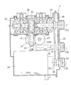
- FIG. 2 which is a schematic diagram showing a schematic configuration of the power generation device 1 connected as an auxiliary machine
- one end portion is directly connected to the first connection shaft (extraction shaft) 11 of the engine E on the input side of the power generation device 1.
- a transmission mechanism input shaft 27 extending in the radial direction R (FIG. 1), and a shaft center connected to the transmission mechanism input shaft 27 and perpendicular to the first connection shaft 11 (in this example, the direction of the engine axis C).
- a transmission mechanism 21 for driving the transmission 22 is provided.
- the input shaft 27 is not limited to the one extending in the radial direction R (FIG. 1), and may be slightly inclined from the radial direction R. That is, the input shaft 27 only needs to have an axis along a direction intersecting with the engine axis C.
- the transmission mechanism 21 includes a transmission shaft 17 having an axis along the front-rear direction FR, a bevel gear 20A provided at the other end of the transmission mechanism input shaft 27, and a bevel gear provided at one end of the transmission shaft 17.
- This passive spur gear 24 becomes an input gear of the transmission 22.
- An intermediate gear 32 is engaged with a transmission output gear 30 provided on the transmission output shaft 29, and is connected to the intermediate gear 32 so that a pump rotation shaft 31 of an oil pump 33 for lubricating oil rotates integrally.
- a generator input gear 39 provided on the rotating shaft 38 of the generator 34 is engaged with the intermediate gear 32.
- the transmission 22 and the generator 34 are spaced apart from each other in the circumferential direction of the low-pressure shaft 9, that is, in the circumferential direction of the engine E.
- the transmission output gear 30, the intermediate gear 32, and the generator input gear 39 are all spur gears, but may be helical gears if a thrust bearing is provided.
- FIG. 3 is a front view showing a state in which the aircraft power generator 1 is attached to the engine E.
- the power generator 1 is attached to the side of the fan case FC of the engine E.
- the power generation device 1 is formed in a vertically long outer shape that is thin with a small thickness when viewed from the direction of the engine axis C and has a large vertical dimension.
- the power generation device 1 can be attached to the side portion of the fan case FC of the engine E with a small protruding side.
- the engine E and the power generator 1 are covered with an engine nacelle N.
- the power generation device 1 may be attached to the side surface of the main body case BC behind the fan case FC.
- the fan case FC and the main body case BC form the engine case.
- the auxiliary machine case 40 that houses the transmission 22, the generator 34, the oil pump 33, and the transmission mechanism 21 of the power generation device 1 has an opening 43 through which the transmission mechanism input shaft 27 passes.
- an auxiliary machine flange 44 that surrounds the periphery of the opening 43 and a first cover 45 that has a through hole 45 a that allows the input shaft 27 to pass through at the center and closes the opening 43.
- a first seal member 46 that seals between the first cover 45 and the input shaft 27 is disposed in the through hole 45a.
- the first cover 45 is for preventing foreign matters from being mixed when the power generation apparatus 1 is stored or transferred, and may be omitted.
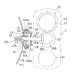
- the power generation device 1 is attached to a fan case FC that is a part of the engine body EB with a structure as shown in FIG. That is, the tip of the annular accessory flange 44 is overlapped with the tip of the mounting pad 12 of the fan case FC.
- an annular fitting protrusion 60 formed at the tip of the auxiliary machine flange 44 is fitted to the inner peripheral surface of the attachment pad 12, and the diameters of the openings 43 and 48 of the auxiliary machine flange 44 with respect to the attachment pad 12.
- the fitting protrusion 60 may be provided on the mounting pad 12.
- both the auxiliary machine flange 44 and the mounting pad 12 are formed with annular connecting projections 44a and 12a projecting radially outward, and the connecting projections 44a and 12a have a cross section as a coupling tool.
- a V-shaped clamp band 50 is attached.
- the mounting surfaces 12aa and 44aa opposite to the opposite sides of the connecting projections 12a and 44a of the mounting pad 12 and the accessory flange 44 are radially outward so as to match the inner surface shape of the clamp band 50.
- the taper is inclined.
- An inner peripheral spline 11 a is formed on the inner peripheral surface of the distal end hole of the first connecting shaft 11, and an outer peripheral spline 27 a that fits the inner peripheral spline 11 a is formed on the outer peripheral surface of the distal end portion of the transmission mechanism input shaft 27. .
- the transmission mechanism input shaft 27 is connected to the first connecting shaft 11 so as to be integrally rotatable and detachable in the axial direction.
- the outer diameter side portion of the opening 48 is closed by a second cover 47 having a through hole 47a of the first connecting shaft 11 at the center.
- a second seal member 49 that seals the space between the second cover 47 and the first connecting shaft 11 in a liquid-tight manner is disposed in the through hole 47a.
- the second seal member 49 prevents foreign matter from entering the fan case FC when the engine E is stored or transferred.
- the periphery of the first connecting shaft 11 in the opening 48 is closed by the second cover 47 and the second seal member 49.
- the power generator 1 includes a transmission mechanism input shaft 27 coupled to the first coupling shaft 11 gear-coupled to the low pressure shaft 9 of the engine E by spline engagement as shown in FIG.
- a continuously variable traction transmission 22 connected to the transmission mechanism input shaft 27 via the transmission mechanism 21; a generator 34 disposed below the traction transmission 22 and driven by the output of the traction transmission 22;
- An oil pump 33 for lubricating oil disposed between the traction transmission 22 and the generator 34 and driven by the output of the traction transmission 22 is provided.
- the transmission mechanism 21, the traction transmission 22, the generator 34, and the oil pump 33 have their axes C22, C34, and C33 parallel to each other and the longitudinal direction FR of the engine E, that is, the direction of the engine axis C. It is along. Even if the rotational speed of the low-pressure shaft 9 fluctuates due to the transmission 22, the generator 34 always rotates at a constant speed and outputs AC power having a constant frequency.
- the rotation of the low-pressure shaft 9 of the engine E shown in FIG. 1 is transmitted to the power generator 1 via the first connecting shaft 11 that is the take-out shaft and the transmission mechanism input shaft 27 shown in FIG.
- power is transmitted from the transmission mechanism input shaft 27 to the generator 34 via the transmission mechanism 21, the traction transmission 22 and the intermediate gear 32, and power is generated by the rotation of the generator 34.
- the transmission mechanism input shaft 27 of FIG. 8 is disposed between the traction transmission 22 and the generator 34 in the circumferential direction of the low-pressure shaft 9, and therefore the traction transmission 22 having a relatively large weight.
- the transmission mechanism input shaft 27 is disposed between the generator 34 and the transmission mechanism input shaft 27, so that the transmission mechanism input shaft 27 is positioned near the center of gravity G shown in FIG. As a result, the overhang moment of the center of gravity G with respect to the mounting flange 44 that forms the mounting surface of the power generator 1 on the engine E is reduced, and the mounting of the power generator 1 on the engine E is stabilized.
- the power generator 1 which is a kind of auxiliary machine is coupled to and supported by the mounting pad 12 of the engine main body EB, so existing accessories and gear boxes are interposed between the power generator 1 and the engine main body EB. There is no need to intervene. Therefore, even if the shape of the generator 1 is increased or the number of auxiliary devices including the generator 1 is increased, the accessory / gearbox is not required, so the overall shape of the engine 1 is increased. It is suppressed.
- the power generator 1 is connected to a first connecting shaft (extraction shaft) 11 that passes through a cover 47 in the opening 48 of the mounting pad 12, and the low-pressure shaft 9 of the engine E is connected to the first connecting shaft 11. Rotation is transmitted to drive.
- the mounting pad 12 provided on the fan case FC has a large diameter shape
- the auxiliary machine case 40 that forms the outer periphery of the power generation device 1 is enlarged even if the power generation device 1 is enlarged.
- the mounting pad 12 having a diameter can be firmly supported. Even in the case of such a large-diameter mounting pad 12, the opening 48 inside the mounting pad 12 is closed by the cover 47 and the seal member 49, so that the opening 48 allows the inside of the fan case FC, that is, the engine body EB. Foreign matter does not enter inside.
- the aircraft engine E has an auxiliary machine flange 44 formed in the auxiliary machine case 40 of the power generator 1, and the auxiliary machine flange 44 is attached to the mounting pad 12 of the fan case FC.
- the auxiliary machine case 40 can be mounted on the fan by a simple operation such that the clamp band 50, which is a coupling tool, is put on the outside of the connecting protrusion 12a of the mounting pad 12 and the connecting protrusion 44a of the auxiliary machine flange 44 by abutting in the axial direction. Can be firmly attached to the case FC.
- the power generator 1 when a large load is taken out from the high-pressure shaft 7 connected to the compressor 2, engine stall is likely to occur at the time of low engine output (ground idle, during descent, etc.), while the power generator 1 has the first connection shaft. 11, the rotary drive is performed by the low-pressure shaft 9 with a small limit on the take-out load, so that large-capacity power generation can be performed.
- the first connecting shaft 11 of the engine E is spline-coupled to the input shaft 27 of the power generator 1, the first connecting shaft 11 of the engine E can rotate integrally with the input shaft 27 of the power generator 1. And detachable in the axial direction. Therefore, the power generator 1 can be easily connected to and disconnected from the low pressure shaft 9.
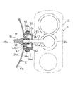
- FIG. 9 is a cross-sectional view of a connecting portion of the power generator 1 in the aircraft engine according to the second embodiment of the present invention.
- This embodiment is different from the first embodiment in that the clamp band 50 of the first embodiment is used. Instead, only the configuration in which the auxiliary machine flange 44 of the auxiliary machine case 40 and the mounting pad 12 of the fan case FC are coupled using the bolt 51 and the nut 52 is used. Thereby, the attachment pad 12 and the auxiliary machine flange 44 which are abutted with each other can be more firmly fixed by fastening the bolt 51 and the nut 52.
- both the mounting surface 44aa of the connecting projection 44a of the accessory flange 44 and the mounting surface 12aa of the connecting projection 12a of the mounting pad 12 are in the radial direction of the opening 43 and the opening 48, that is, the input shaft 27 and the first connecting shaft 11. It is a flat surface extended in the direction orthogonal to the axial center.
- the present invention is not limited to the power generation apparatus 1 shown in the embodiment as an auxiliary machine connected to the engine rotation shaft, and can be similarly applied to, for example, a fuel pump or an oil pump.
- the engine rotation shaft for connecting the auxiliary machine is not limited to the low pressure shaft 9 shown in the embodiment, but may be the high pressure shaft 7.
- the engine E may be a single shaft type.
Landscapes
- Engineering & Computer Science (AREA)
- Chemical & Material Sciences (AREA)
- Combustion & Propulsion (AREA)
- General Engineering & Computer Science (AREA)
- Mechanical Engineering (AREA)
- Connection Of Motors, Electrical Generators, Mechanical Devices, And The Like (AREA)
- Friction Gearing (AREA)
- Sealing Devices (AREA)
- General Details Of Gearings (AREA)
- Hybrid Electric Vehicles (AREA)
Abstract
Priority Applications (5)
| Application Number | Priority Date | Filing Date | Title |
|---|---|---|---|
| EP12767294.7A EP2696057B1 (fr) | 2011-04-07 | 2012-04-04 | Moteur d'aéronef |
| CN201280015823.0A CN103459806B (zh) | 2011-04-07 | 2012-04-04 | 航空器用发动机 |
| JP2013508912A JP5583847B2 (ja) | 2011-04-07 | 2012-04-04 | 航空機用エンジン |
| US14/110,016 US9765861B2 (en) | 2011-04-07 | 2012-04-04 | Sealing arrangement of accessory to aircraft engine |
| CA2832155A CA2832155C (fr) | 2011-04-07 | 2012-04-04 | Moteur d'aeronef |
Applications Claiming Priority (2)
| Application Number | Priority Date | Filing Date | Title |
|---|---|---|---|
| JP2011-085428 | 2011-04-07 | ||
| JP2011085428 | 2011-04-07 |
Publications (1)
| Publication Number | Publication Date |
|---|---|
| WO2012137844A1 true WO2012137844A1 (fr) | 2012-10-11 |
Family
ID=46969237
Family Applications (2)
| Application Number | Title | Priority Date | Filing Date |
|---|---|---|---|
| PCT/JP2012/059247 WO2012137844A1 (fr) | 2011-04-07 | 2012-04-04 | Moteur d'aéronef |
| PCT/JP2012/059246 WO2012137843A1 (fr) | 2011-04-07 | 2012-04-04 | Appareil générateur pour aéronef |
Family Applications After (1)
| Application Number | Title | Priority Date | Filing Date |
|---|---|---|---|
| PCT/JP2012/059246 WO2012137843A1 (fr) | 2011-04-07 | 2012-04-04 | Appareil générateur pour aéronef |
Country Status (6)
| Country | Link |
|---|---|
| US (2) | US9890839B2 (fr) |
| EP (2) | EP2696058B1 (fr) |
| JP (2) | JP5703370B2 (fr) |
| CN (2) | CN103459806B (fr) |
| CA (2) | CA2832153C (fr) |
| WO (2) | WO2012137844A1 (fr) |
Cited By (1)
| Publication number | Priority date | Publication date | Assignee | Title |
|---|---|---|---|---|
| WO2021162102A1 (fr) * | 2020-02-14 | 2021-08-19 | 川崎重工業株式会社 | Moteur à turbine à gaz |
Families Citing this family (23)
| Publication number | Priority date | Publication date | Assignee | Title |
|---|---|---|---|---|
| US9297314B2 (en) * | 2012-12-19 | 2016-03-29 | United Technologies Corporation | Gas turbine engine with accessory gear box |
| FR3005491B1 (fr) * | 2013-05-10 | 2015-06-05 | Hispano Suiza Sa | Integration de pompes a une boite d'engrenages annexe a un moteur d'aeronef |
| FR3006997B1 (fr) * | 2013-06-14 | 2016-12-23 | Airbus | Aeronef a moyens de propulsion electriques |
| WO2015047577A1 (fr) * | 2013-09-26 | 2015-04-02 | United Technologies Corporation | Moteur à turbine à gaz avec système de lubrification fractionné |
| FR3011882B1 (fr) * | 2013-10-11 | 2018-01-26 | Hispano Suiza Sa | Boitier d'entrainement d'accessoires pour turbomachine |
| FR3016408B1 (fr) * | 2014-01-16 | 2019-05-31 | Safran Transmission Systems | Ensemble d'entrainement d'accessoires pour turbomachine d'aeronef |
| FR3017658B1 (fr) * | 2014-02-18 | 2019-04-12 | Safran Transmission Systems | Boitier d'entrainement d'equipements pour turbomachine |
| US10500464B2 (en) * | 2014-03-20 | 2019-12-10 | Shooter's Touch, Llc | Basketball performance monitoring system |
| JP6511265B2 (ja) | 2014-12-24 | 2019-05-15 | 川崎重工業株式会社 | 航空機用エンジン装置 |
| JP6554282B2 (ja) | 2014-12-24 | 2019-07-31 | 川崎重工業株式会社 | 航空機用エンジン装置 |
| JP6709021B2 (ja) | 2015-03-09 | 2020-06-10 | 川崎重工業株式会社 | トロイダル無段変速機および駆動機構一体型発電装置 |
| JP6343243B2 (ja) | 2015-03-09 | 2018-06-13 | 川崎重工業株式会社 | 航空機用発電装置 |
| JP6505477B2 (ja) * | 2015-03-13 | 2019-04-24 | 川崎重工業株式会社 | 変速装置及びそれを備える発電システム |
| FR3041052B1 (fr) | 2015-09-14 | 2018-07-27 | Safran Transmission Systems | Boitier d'entrainement d'equipements dans une turbomachine |
| GB201610234D0 (en) * | 2016-06-13 | 2016-07-27 | Rolls Royce Plc | An accessory gearbox assembly and a gas turbine engine comprising an accessory gearbox assembly |
| CN106763769A (zh) * | 2016-11-15 | 2017-05-31 | 中国舰船研究设计中心 | 一种机械连接面的密性装置 |
| US10533499B2 (en) * | 2017-10-03 | 2020-01-14 | Hamilton Sundstrand Corporation | Seal plate located between two housing portions in an integrated drive generator |
| US11346427B2 (en) | 2019-02-13 | 2022-05-31 | Raytheon Technologies Corporation | Accessory gearbox for gas turbine engine with variable transmission |
| US20200284326A1 (en) * | 2019-03-05 | 2020-09-10 | Hamilton Sundstrand Corporation | Continuously variable transmission for ram air turbines |
| JP7316135B2 (ja) * | 2019-07-22 | 2023-07-27 | 川崎重工業株式会社 | トロイダル無段変速機及び航空機用駆動機構一体型発電装置 |
| FR3099209B1 (fr) | 2019-07-26 | 2021-06-25 | Safran Aircraft Engines | Dispositif d’entrainement d’une génératrice d’une turbomachine d’aéronef et procédé de régulation de la vitesse d’une telle génératrice |
| US20230407794A1 (en) | 2020-10-28 | 2023-12-21 | Kawasaki Jukogyo Kabushiki Kaisha | Gas turbine engine for use in aircraft |
| FR3117530B1 (fr) * | 2020-12-15 | 2024-01-05 | Safran Aircraft Engines | Ensemble pour turbomachine d’aéronef comprenant un support d’équipements |
Citations (5)
| Publication number | Priority date | Publication date | Assignee | Title |
|---|---|---|---|---|
| US7386983B2 (en) | 2004-02-25 | 2008-06-17 | United Technologies Corporation | Apparatus for driving an accessory gearbox in a gas turbine engine |
| JP2008190526A (ja) * | 2007-01-31 | 2008-08-21 | Hispano Suiza | ガスタービン始動機/発電機用の分散構造体 |
| EP1980732A2 (fr) * | 2007-04-03 | 2008-10-15 | General Electric Company | Système de prise de force et ensemble de turbine à gaz l'incluant |
| JP2009532613A (ja) * | 2006-04-04 | 2009-09-10 | エムテーウー・アエロ・エンジンズ・ゲーエムベーハー | 発電機ユニットを備えたジェットエンジン |
| US7707909B2 (en) | 2005-10-21 | 2010-05-04 | Hispano-Suiza | Device for driving accessory machines of a gas turbine engine |
Family Cites Families (19)
| Publication number | Priority date | Publication date | Assignee | Title |
|---|---|---|---|---|
| US2978869A (en) | 1956-11-01 | 1961-04-11 | Bristol Siddeley Engines Ltd | Engine accessory mounting arrangements |
| US3688560A (en) | 1971-01-29 | 1972-09-05 | Gen Electric | Gas turbine engine with improved auxiliary power take-off |
| FR2152362B1 (fr) | 1971-09-07 | 1974-05-10 | Snecma | |
| US3834161A (en) * | 1973-06-01 | 1974-09-10 | Us Air Force | Dual mode auxiliary power unit |
| US4252035A (en) | 1978-08-11 | 1981-02-24 | Sundstrand Corporation | Integrated drive-generator system |
| US4712370A (en) * | 1986-04-24 | 1987-12-15 | The United States Of America As Represented By The Secretary Of The Air Force | Sliding duct seal |
| US5470114A (en) * | 1994-11-14 | 1995-11-28 | General Electric Company | Coupling assembly |
| FR2767374B1 (fr) | 1997-08-13 | 1999-09-17 | Hispano Suiza Sa | Agencement d'etancheite pour un bout d'arbre |
| JP3440287B2 (ja) | 1999-12-01 | 2003-08-25 | 川崎重工業株式会社 | 航空機搭載発電機の定速駆動方法および定速駆動装置 |
| JP2001317374A (ja) | 2000-04-28 | 2001-11-16 | Honda Motor Co Ltd | ガスタービンエンジンの補機駆動ユニット |
| US7975465B2 (en) | 2003-10-27 | 2011-07-12 | United Technologies Corporation | Hybrid engine accessory power system |
| US7500365B2 (en) * | 2005-05-05 | 2009-03-10 | United Technologies Corporation | Accessory gearbox |
| US7805947B2 (en) * | 2005-05-19 | 2010-10-05 | Djamal Moulebhar | Aircraft with disengageable engine and auxiliary power unit components |
| FR2894621B1 (fr) | 2005-12-09 | 2011-10-14 | Hispano Suiza Sa | Systeme d'entrainement de machines auxiliaires d'un turbomoteur a double corps |
| JP4906455B2 (ja) | 2006-09-26 | 2012-03-28 | 本田技研工業株式会社 | 内燃機関のクランクケース構造 |
| US20090188334A1 (en) * | 2008-01-25 | 2009-07-30 | United Technologies Corp. | Accessory Gearboxes and Related Gas Turbine Engine Systems |
| US8172512B2 (en) | 2008-04-23 | 2012-05-08 | Hamilton Sundstrand Corporation | Accessory gearbox system with compressor driven seal air supply |
| FR2941744B1 (fr) | 2009-01-30 | 2011-09-16 | Hispano Suiza Sa | Ensemble d'un boitier de relais d'accessoires et d'un reservoir d'huile |
| JP4700113B2 (ja) | 2009-02-06 | 2011-06-15 | 川崎重工業株式会社 | 航空機用発電装置 |
-
2012
- 2012-04-04 EP EP12767296.2A patent/EP2696058B1/fr active Active
- 2012-04-04 CA CA2832153A patent/CA2832153C/fr active Active
- 2012-04-04 US US14/110,050 patent/US9890839B2/en active Active
- 2012-04-04 WO PCT/JP2012/059247 patent/WO2012137844A1/fr active Application Filing
- 2012-04-04 JP JP2013508911A patent/JP5703370B2/ja active Active
- 2012-04-04 CN CN201280015823.0A patent/CN103459806B/zh not_active Expired - Fee Related
- 2012-04-04 CN CN201280016072.4A patent/CN103459807B/zh not_active Expired - Fee Related
- 2012-04-04 WO PCT/JP2012/059246 patent/WO2012137843A1/fr active Application Filing
- 2012-04-04 CA CA2832155A patent/CA2832155C/fr active Active
- 2012-04-04 US US14/110,016 patent/US9765861B2/en active Active
- 2012-04-04 EP EP12767294.7A patent/EP2696057B1/fr active Active
- 2012-04-04 JP JP2013508912A patent/JP5583847B2/ja active Active
Patent Citations (5)
| Publication number | Priority date | Publication date | Assignee | Title |
|---|---|---|---|---|
| US7386983B2 (en) | 2004-02-25 | 2008-06-17 | United Technologies Corporation | Apparatus for driving an accessory gearbox in a gas turbine engine |
| US7707909B2 (en) | 2005-10-21 | 2010-05-04 | Hispano-Suiza | Device for driving accessory machines of a gas turbine engine |
| JP2009532613A (ja) * | 2006-04-04 | 2009-09-10 | エムテーウー・アエロ・エンジンズ・ゲーエムベーハー | 発電機ユニットを備えたジェットエンジン |
| JP2008190526A (ja) * | 2007-01-31 | 2008-08-21 | Hispano Suiza | ガスタービン始動機/発電機用の分散構造体 |
| EP1980732A2 (fr) * | 2007-04-03 | 2008-10-15 | General Electric Company | Système de prise de force et ensemble de turbine à gaz l'incluant |
Non-Patent Citations (1)
| Title |
|---|
| See also references of EP2696057A4 |
Cited By (1)
| Publication number | Priority date | Publication date | Assignee | Title |
|---|---|---|---|---|
| WO2021162102A1 (fr) * | 2020-02-14 | 2021-08-19 | 川崎重工業株式会社 | Moteur à turbine à gaz |
Also Published As
| Publication number | Publication date |
|---|---|
| JPWO2012137844A1 (ja) | 2014-07-28 |
| CA2832153C (fr) | 2015-02-10 |
| CN103459807B (zh) | 2016-08-17 |
| EP2696058B1 (fr) | 2017-10-11 |
| JP5583847B2 (ja) | 2014-09-03 |
| CA2832153A1 (fr) | 2012-10-11 |
| EP2696057A4 (fr) | 2015-04-22 |
| CN103459807A (zh) | 2013-12-18 |
| EP2696058A4 (fr) | 2015-04-22 |
| CN103459806A (zh) | 2013-12-18 |
| WO2012137843A1 (fr) | 2012-10-11 |
| CN103459806B (zh) | 2016-01-20 |
| EP2696057B1 (fr) | 2017-10-18 |
| EP2696058A1 (fr) | 2014-02-12 |
| CA2832155A1 (fr) | 2012-10-11 |
| JPWO2012137843A1 (ja) | 2014-07-28 |
| US9765861B2 (en) | 2017-09-19 |
| JP5703370B2 (ja) | 2015-04-15 |
| US20140026589A1 (en) | 2014-01-30 |
| US20140038770A1 (en) | 2014-02-06 |
| EP2696057A1 (fr) | 2014-02-12 |
| CA2832155C (fr) | 2015-02-24 |
| US9890839B2 (en) | 2018-02-13 |
Similar Documents
| Publication | Publication Date | Title |
|---|---|---|
| JP5583847B2 (ja) | 航空機用エンジン | |
| US10202905B2 (en) | Gas turbine architecture | |
| US8814502B2 (en) | Dual input drive AGB for gas turbine engines | |
| US7386983B2 (en) | Apparatus for driving an accessory gearbox in a gas turbine engine | |
| JP5620519B2 (ja) | 航空機タービンエンジン用二重反転プロペラシステム | |
| US9353690B2 (en) | Interface with mount features for precise alignment | |
| US20160097331A1 (en) | Gas turbine architecture | |
| EP1574687A1 (fr) | Système d'entraínement mécanique pour une boíte d'engrenage d'équipement auxiliaire | |
| JP2013515914A (ja) | 高圧パワーオフテイクおよび低圧パワーオフテイクを備えるターボファンエンジン | |
| US11067006B2 (en) | Gas turbine engine system with synchronization features for gearbox operation | |
| EP3306140A1 (fr) | Ensemble d' une boîte de vitesses planétaire | |
| US4118997A (en) | Bevel gearing | |
| US20160333793A1 (en) | Accessory gearbox assembly for an aircraft turbine engine | |
| US11326523B2 (en) | Gas turbine engine with accessory gearbox | |
| US11754002B2 (en) | Epicyclic reduction gear for a turbomachine | |
| US20240052789A1 (en) | Turbomachine module equipped with an electric machine, and turbomachine equipped with such a module | |
| US11906017B1 (en) | Drive assembly and method of assembly | |
| JP2021528589A (ja) | 少なくとも2つの本体と、動力引出手段を有する航空機のタービンエンジン |
Legal Events
| Date | Code | Title | Description |
|---|---|---|---|
| 121 | Ep: the epo has been informed by wipo that ep was designated in this application |
Ref document number: 12767294 Country of ref document: EP Kind code of ref document: A1 |
|
| ENP | Entry into the national phase |
Ref document number: 2013508912 Country of ref document: JP Kind code of ref document: A |
|
| ENP | Entry into the national phase |
Ref document number: 2832155 Country of ref document: CA |
|
| WWE | Wipo information: entry into national phase |
Ref document number: 14110016 Country of ref document: US |
|
| NENP | Non-entry into the national phase |
Ref country code: DE |
|
| REEP | Request for entry into the european phase |
Ref document number: 2012767294 Country of ref document: EP |
|
| WWE | Wipo information: entry into national phase |
Ref document number: 2012767294 Country of ref document: EP |