WO2012137750A1 - 長光路長フローセル - Google Patents
長光路長フローセル Download PDFInfo
- Publication number
- WO2012137750A1 WO2012137750A1 PCT/JP2012/059024 JP2012059024W WO2012137750A1 WO 2012137750 A1 WO2012137750 A1 WO 2012137750A1 JP 2012059024 W JP2012059024 W JP 2012059024W WO 2012137750 A1 WO2012137750 A1 WO 2012137750A1
- Authority
- WO
- WIPO (PCT)
- Prior art keywords
- flow path
- cylindrical
- cross
- light
- flow cell
- Prior art date
- Legal status (The legal status is an assumption and is not a legal conclusion. Google has not performed a legal analysis and makes no representation as to the accuracy of the status listed.)
- Ceased
Links
Images


Classifications
-
- G—PHYSICS
- G01—MEASURING; TESTING
- G01N—INVESTIGATING OR ANALYSING MATERIALS BY DETERMINING THEIR CHEMICAL OR PHYSICAL PROPERTIES
- G01N21/00—Investigating or analysing materials by the use of optical means, i.e. using sub-millimetre waves, infrared, visible or ultraviolet light
- G01N21/01—Arrangements or apparatus for facilitating the optical investigation
- G01N21/03—Cuvette constructions
- G01N21/05—Flow-through cuvettes
-
- G—PHYSICS
- G01—MEASURING; TESTING
- G01N—INVESTIGATING OR ANALYSING MATERIALS BY DETERMINING THEIR CHEMICAL OR PHYSICAL PROPERTIES
- G01N30/00—Investigating or analysing materials by separation into components using adsorption, absorption or similar phenomena or using ion-exchange, e.g. chromatography or field flow fractionation
- G01N30/02—Column chromatography
- G01N30/62—Detectors specially adapted therefor
- G01N30/74—Optical detectors
-
- G—PHYSICS
- G01—MEASURING; TESTING
- G01N—INVESTIGATING OR ANALYSING MATERIALS BY DETERMINING THEIR CHEMICAL OR PHYSICAL PROPERTIES
- G01N21/00—Investigating or analysing materials by the use of optical means, i.e. using sub-millimetre waves, infrared, visible or ultraviolet light
- G01N21/01—Arrangements or apparatus for facilitating the optical investigation
- G01N21/03—Cuvette constructions
- G01N2021/0346—Capillary cells; Microcells
-
- G—PHYSICS
- G01—MEASURING; TESTING
- G01N—INVESTIGATING OR ANALYSING MATERIALS BY DETERMINING THEIR CHEMICAL OR PHYSICAL PROPERTIES
- G01N21/00—Investigating or analysing materials by the use of optical means, i.e. using sub-millimetre waves, infrared, visible or ultraviolet light
- G01N21/01—Arrangements or apparatus for facilitating the optical investigation
- G01N21/03—Cuvette constructions
- G01N2021/0378—Shapes
- G01N2021/0382—Frustoconical, tapered cell
-
- G—PHYSICS
- G01—MEASURING; TESTING
- G01N—INVESTIGATING OR ANALYSING MATERIALS BY DETERMINING THEIR CHEMICAL OR PHYSICAL PROPERTIES
- G01N30/00—Investigating or analysing materials by separation into components using adsorption, absorption or similar phenomena or using ion-exchange, e.g. chromatography or field flow fractionation
- G01N30/02—Column chromatography
- G01N30/62—Detectors specially adapted therefor
- G01N30/74—Optical detectors
- G01N2030/746—Optical detectors detecting along the line of flow, e.g. axial
Definitions
- the present invention relates to a flow cell for spectroscopic analysis of a sample, and more particularly to a flow cell for spectroscopic analysis used in a liquid analyzer.
- a device for spectroscopic analysis of samples with ultraviolet, visible, or infrared light which is provided in a liquid analyzer such as a liquid chromatograph, is equipped with a flow cell, and the emission intensity represented by absorbance or fluorescence using the flow cell. Etc. are measured.
- the longer the optical path length in the flow cell the higher the analytical sensitivity.
- the position distribution of the sample is often expanded in the flow cell due to a hydrodynamic effect, so that the peak signal value obtained is smaller than the peak signal value that should be originally obtained, resulting in a decrease in sensitivity.
- the spread of the position distribution of the sample not only lowers the sensitivity but also lowers the resolution at the same time.
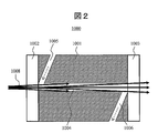
- FIG. 1 is a schematic perspective view of a flow cell having a cylindrical flow path
- FIG. 2 is a cross-sectional view of a cross section 1009 passing through the center of the optical path in FIG.
- the flow cell body 1001 is provided with window materials 1002 and 1003, and the sample solution introduced from the fluid introduction unit 1005 passes through the cylindrical channel 1004 and is discharged from the fluid discharge unit 1006.
- Measuring light 1008 is incident on the cylindrical channel 1004 from a light source, and light absorption and light emission occur.
- the refractive index fluctuation of the solution caused by external factors such as temperature fluctuation, pressure fluctuation, solution composition fluctuation, etc. fluctuates the ratio of these reflected light and scattered light to incident light, and apparent absorbance fluctuation, that is, noise Or the problem of being detected as drift is known.
- this effect is called a liquid lens effect because it is caused by a change in the refractive index of the solution inside the channel (Non-Patent Document 2). Therefore, in the cylindrical flow path, there is a trade-off relationship between the reduction in the spread of the position distribution of the sample and the improvement in sensitivity.
- Patent Document 3 a fluorine-based polymer, particularly Teflon (registered trademark) AF, which is a material having a lower refractive index than water, which is a solvent having the highest refractive index among frequently used in spectroscopic analysis, is flown.
- a system has been devised that achieves total reflection of light by applying to the inner walls of the road.
- Patent Document 4 a double fused silica capillary is used for the flow cell, a measuring solvent is used for the inner capillary, and a solvent having a lower refractive index than that, particularly a perfluoro solvent, is used for the outer capillary.
- a system has been devised in which light is totally reflected by the arrangement.
- the flow path expanded in a taper shape increases the flow cell capacity and the sample expands more than the cylindrical flow path, so the time that the sample stays in the flow path increases and the spread of the position distribution of the sample increases. End up.
- the amount of light decreases when the measurement flow channel is not fully reflected due to foreign matter adhesion etc. And sensitivity will fall.
- the present invention provides a flow cell that can improve the sensitivity while reducing the spread of the position distribution of the sample by devising the channel structure.
- a flow cell of a representative form of the present invention includes a main body having a sample flow path through which measurement light passes, and window materials provided on the light incident side and the light output side of the main body, and the sample flow path is a fluid. It has the 1st cylindrical flow path connected to the introduction part, and the 2nd cylindrical flow path connected to the fluid discharge part.
- the first cylindrical channel and the second cylindrical channel have a shape in which a cross-sectional area perpendicular to the incident optical axis is constant or continuously increases along the traveling direction of the incident light.
- the cross-sectional area perpendicular to the incident optical axis at the light exit end of the cylindrical flow path is equal to or smaller than the cross-sectional area perpendicular to the incident optical axis at the light incident end of the second cylindrical flow path.
- the cross-sectional area of the fluid discharge part is larger than the cross-sectional area of the fluid introduction part.
- the main body is made of a material that prevents reflection of light in the ultraviolet to infrared wavelength range, or the inner wall surfaces of the first and second channels prevent reflection of light in the ultraviolet to infrared wavelength range. It is preferably modified with a material having properties.
- the focal position of incident light from the light source is located closer to the light source than the fluid discharge side of the first cylindrical flow path.
- the amount of measurement light hitting the inner wall of the sample channel can be reduced and the sensitivity can be improved.
- the effect of rectifying the fluid is obtained by the first cylindrical channel, and the spread of the position distribution of the sample can be reduced because the sample flows quickly.
- Sectional drawing which shows an example of the flow cell by this invention Sectional drawing which shows an example of the flow cell by this invention. Sectional drawing which shows an example of the flow cell by this invention. Sectional drawing which shows an example of the flow cell by this invention. Sectional drawing which shows an example of the flow cell which has a flow path with an elliptical cross section. Sectional drawing which shows an example of the flow cell which has a polygonal cross section. Sectional drawing which shows an example of the flow cell by this invention. Sectional drawing which shows an example of the flow cell by this invention. Sectional drawing which shows an example of the flow cell by this invention. Sectional drawing which shows an example of the flow cell by this invention. Sectional drawing which shows an example of the flow cell by this invention. Sectional drawing which shows an example of the flow cell by this invention. Sectional drawing which shows an example of the flow cell by this invention. Sectional drawing which shows the other example of a fluid discharge part.
- Sectional drawing which shows the other example of a fluid discharge part. Sectional drawing which shows the other example of a fluid discharge part. Schematic which shows an example of a liquid chromatography apparatus. Schematic which shows an example of a spectrophotometer. Schematic which shows an example of a spectrophotometer. The figure which shows a band expansion measurement result. The figure which shows a noise measurement result.
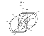
- FIG. 4 is a schematic diagram of an embodiment of a flow cell according to the present invention.
- the flow cell 100 includes a flow cell body 101 and window materials 102 and 103 that transmit two pieces of light. Inside the flow cell body 101, the first cylindrical flow path 104 on the measurement light incident side, the second cylindrical flow path 105 on the measurement light emission side, the fluid introduction part 106 for introducing fluid into the flow cell 100, and the fluid are discharged A fluid discharge portion 107 is provided.
- the light source is disposed on the first cylindrical flow path 104 side
- the detector is disposed on the second cylindrical flow path 105 side. Measurement light enters from the channel 104.
- the measurement light that has passed through the first cylindrical channel 104 and the second cylindrical channel 105 is detected by a detector.
- the sample solution is introduced from the fluid introduction unit 106, and is discharged from the fluid discharge unit 107 through the first cylindrical channel 104 and the second cylindrical channel 105.
- the window members 102 and 103 may be optical parts that transmit light, and may be optical parts such as quartz glass and lenses.
- the flow cell body 101 may be any material that prevents reflection of light in the ultraviolet to infrared wavelength region.
- black quartz is desirable, and a resin such as glass fiber reinforced polycarbonate mixed with carbon or a material such as carbon fiber may be used.
- the inner walls of the first cylindrical channel 104 and the second cylindrical channel 105 are modified by a method such as coating, plating, or vapor deposition with a material that prevents reflection of light in the ultraviolet to infrared wavelength region. May be.
- the flow cell body 101 may be a metal such as stainless steel or aluminum steel, a silicon oxide such as fused silica or quartz glass, or a resin such as polycarbonate.
- a material such as black quartz, zinc oxide, aluminum oxide, diamond-like carbon may be used.
- the outer shape of the flow cell shown in FIG. 4 has a shape obtained by cutting a part of a cylindrical shape for the convenience of installing a pipe for flowing a solution, but an important point is a cylindrical path through which fluid and measurement light pass. Therefore, it is not always necessary to have such a shape, for example, a simple cylindrical shape, a truncated cone shape, a rectangular tubular shape, a truncated cone shape, or a place where the flow cell should be placed based on these shapes.
- the shape processed in this way may be used.
- a method of forming the flow cell body 101 a method of drilling pores by drilling, a groove is formed on the surface of the cell body previously divided in half, and the surface is sufficiently polished by a chemical polishing method or the like, followed by optical bonding. There is a way to assemble the body.
- a method for forming the entire flow cell there are a method of mechanically pressing and a method of welding with heat.
- FIG. 5 is a cross-sectional view of the flow cell cut along a plane 408 passing through the flow path center of FIG.
- Two window members 102 and 103 are provided on both sides of the flow cell body 101, and a first cylindrical channel 104, a second cylindrical channel 105, and a first cylinder through which measurement light passes are provided inside the body.
- a fluid introduction part 106 for introducing a sample to the light incident end side of the cylindrical flow path 104 and a fluid discharge part 107 for discharging the sample from the light emission end side of the second cylindrical flow path are provided.
- the first cylindrical channel 104 has a cylindrical shape
- the second cylindrical channel 105 has a truncated cone shape whose cross-sectional area increases along the traveling direction of the measurement light emitted from the light source. It has the shape of The cross-sectional area of the light incident end of the second frustoconical channel 105 is equal to the cross-sectional area of the light exit end of the first cylindrical channel 104, and the focal position of light from the light source is the first cylindrical channel. 104 outside.
- the diameter of the cylindrical flow path 104 is 0.3 mm or more and 1 mm or less
- the total optical path length of the flow cell is 5 mm or more and 50 mm or less
- the cone angle of the truncated cone-shaped flow path 105 is 1 degree or more and 30 degrees.
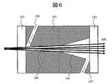
- the flow path diameters of the fluid introduction part 106 and the fluid discharge part 107 are the same and are preferably 0.2 mm or more and 0.5 mm or less. With such a shape, as shown in FIG. 6, not only can the sensitivity be improved by reducing the amount of measurement light 608 that strikes the inner wall of the flow path, but also the spread of the sample position can be reduced by the rectification effect. Become.
- the reflection / scattering Light is reduced by the material that prevents reflection of light in the ultraviolet to infrared wavelength region, which is adopted as a material for the entire flow cell or a modification material for the inner walls of the first and second channels, and can further improve sensitivity.
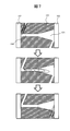
- FIG. 7 the conceptual diagram of the time-dependent change of a flow was shown. As shown in FIG. 7, the flow is adjusted by the first cylindrical flow path 104 acting as a fluid running section, and the sample does not expand in the second cylindrical flow path 105, so that the sample is quickly expanded. Since the residence time in the channel is reduced by flowing in the channel, it is possible to reduce the spread of the position distribution of the sample in the channel.
- the flow path diameters of the fluid introduction part 106 and the fluid discharge part 107 are preferably 0.2 mm or more and 0.5 mm or less.
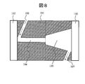
- the embodiment shown in FIG. 8 includes two window members 102 and 103 on both sides of the flow cell body 101, and a first cylindrical channel 104 and a second truncated cone shape through which measurement light passes inside the body.
- a flow path 105, a fluid introduction part 106, and a fluid discharge part 107 are provided.
- the second cylindrical channel 105 has a truncated cone shape equivalent to that of FIG. 5, and the cross-sectional area of the light incident end thereof is the first cylindrical channel. This is an example that is larger than the cross-sectional area of the light emitting end.
- the diameter of the cylindrical flow path 104 is 0.3 mm or more and 1 mm or less
- the total optical path length of the flow cell is 5 mm or more and 50 mm or less
- the cone angle of the truncated cone-shaped flow path 105 is 1 degree or more and 30 degrees. The following is preferred.
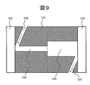
- FIG. 9 shows an embodiment in which the second cylindrical channel 105 is a cylindrical channel having a cross-sectional area larger than that of the first cylindrical channel 104. More specifically, the diameter of the first cylindrical channel 104 is 0.3 mm or more and 1 mm or less, the diameter of the second cylindrical channel 105 is 0.4 mm or more and 10 mm or less, and the total optical path length of the flow cell is 5 mm or more and 50 mm or less are preferable.
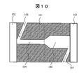
- FIG. 10 shows a connection portion between the second cylindrical channel 105 and the first cylindrical channel 104 based on the cylindrical channel having a cross-sectional area larger than that of the first cylindrical channel 104.
- An embodiment is shown in which the cross-sectional area changes so as to continuously expand in the vicinity.
- the diameter of the first cylindrical channel 104 is 0.3 mm or more and 1 mm or less
- the diameter of the second cylindrical channel 105 is 0.4 mm or more and 10 mm or less
- the total optical path length of the flow cell is 5 mm or more and 50 mm or less
- the length of the portion where the cross-sectional area of the second cylindrical flow path 105 continuously changes in the vicinity of the connecting portion with the first cylindrical flow path 104 is the first and second It is about 5 to 30% of the sum of the lengths of the cylindrical channels.
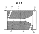
- FIG. 11 shows an embodiment in which the cross-sectional area of the second cylindrical channel 105 is changed so as to continuously expand along the streamline of the flow field inside the channel. More specifically, the diameter of the first cylindrical flow path 104 is 0.3 mm or more and 1 mm or less, and the diameter of the light emitting end of the second cylindrical flow path 104 is 0.4 mm or more and 10 mm or less. The total optical path length is preferably 5 mm or more and 50 mm or less.
- the shape of the second cylindrical flow path 105 a flow path in which the cross-sectional area of the entire flow path is continuously changing along the flow line of the flow field inside the flow path is taken as an example.
- the shape may be a parabolic shape or a hyperbolic shape, and a shape in which the cross-sectional area increases from the fluid introduction side to the fluid discharge side is desirable.
- the above-described cylindrical flow path has a rotationally symmetric shape with the central axis of the flow path as a rotation axis, but it does not necessarily have a rotationally symmetric shape, and an asymmetrical shape, for example, an asymmetric frustoconical flow It may be a road.
- the two flow paths having different shapes have been called the first cylindrical flow path and the second cylindrical flow path.
- the boundary of the cylindrical flow path can be defined as a position where the area of the cross section perpendicular to the incident optical axis or the increase rate of the area changes.
- the boundary between two flow paths is defined at the position where the area changes, in the flow cell of the embodiment shown in FIGS. 8 and 9, and the boundary between the two flow paths at the position where the area increase rate changes. Is defined in the flow cell of the embodiment shown in FIGS. 5, 10, and 11.
- the first cylindrical channel is limited to a cylindrical channel having a constant cross-sectional area, but the first cylindrical channel may not have a constant cross-sectional area.
- the same effect can be obtained even if both the first cylindrical channel 104 and the second cylindrical channel 105 are frustoconical channels.
- the cross-sectional area of the light exit end of the first cylindrical channel 104 is the second cylindrical channel 105 in order to prevent the measurement light from hitting the inner wall of the channel while having the function of adjusting the flow.
- the first cylindrical flow path 104 is a cylindrical flow path whose cross-sectional area slightly increases from the fluid introduction side to the fluid discharge side
- the channel 105 is preferably a cylindrical channel whose cross-sectional area increases from the fluid introduction side toward the fluid discharge side.
- the first cylindrical channel is a cylindrical channel
- the second cylindrical channel is a truncated cone-shaped channel or a shape along the flow line of the flow field inside the channel.
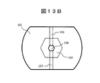
- FIGS. 13A and 13B are schematic sectional views of the flow cell as viewed from the window member 102 side.
- 13A and 13B are schematic sectional views of the flow cell as viewed from the window member 102 side.
- the sensitivity can be further improved by adjusting the optical system of the liquid analyzer or changing the arrangement of the flow cell.
- FIG. 6 shows an example in which the focus position of the measurement light is arranged outside the flow cell.
- the focus position of the measurement light is inside the flow cell, that is, inside the first cylindrical channel 104 as shown in FIG. It may be arranged.
- the ratio of the optical path length of the first cylindrical channel 104 and the optical path length of the second cylindrical channel 105 to the total optical path length of the flow cell is limited by the focal position of the measurement light. It is desirable to optimize in view of the position expansion of the internal sample.
- the measurement light from the light source is preferably as narrow as possible and has a smaller incident angle.
- a material that absorbs ultraviolet, visible, and infrared light is used for the flow cell body in order to prevent random scattering and absorption of the measurement light on the inner wall of the flow path. Is desirable.
- a cylindrical flow path is often used as the shape of the fluid introduction part and the fluid discharge part, and a Z shape (a shape that enters obliquely with respect to the optical path) or a crank shape is often used together with the optical path portion. .
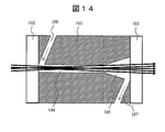
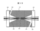
- FIG. 15 shows an embodiment of a flow cell in which a third cylindrical channel is newly added to the first and second cylindrical channels on the light source side.
- Two window members 102 and 103 are provided on both sides of the flow cell body 101, and a truncated cone-shaped channel 108, which is a third channel through which measurement light passes, and a first cylindrical channel are provided inside the body.
- a cylindrical channel 104 and a truncated cone channel 105 which is a second cylindrical channel are continuously formed.
- a fluid introduction part 106 is connected to the light incident end of the third flow path 108, and a fluid discharge part 107 is connected to the light emission end of the second cylindrical flow path 105.
- This channel structure has a structure in which a truncated cone channel whose sectional area continuously decreases with respect to the traveling direction of the measurement light is newly added to the light source side of the channel structure shown in FIG. More specifically, the diameter of the cylindrical channel 104 is 0.3 mm or more and 1 mm or less, the total optical path length of the flow cell is 10 mm or more and 60 mm or less, and the cone angle of the frustoconical channels 105 and 108 is 1 degree or more.
- the flow path diameter of the fluid introduction part 106 and the fluid discharge part 107 is preferably 0.2 mm or more and 0.5 mm or less at 30 degrees or less. At this time, it is desirable that the focus position of the measurement light from the light source is arranged on the fluid introduction side rather than the fluid discharge side of the first cylindrical channel 104 as shown in FIG.
- the flow path through which the measurement light of the entire flow cell passes is composed of three or more cylindrical flow paths, in order to maximize the effects of the present invention, Starting from the site with the smallest cross-sectional area, the flow path on the fluid discharge side of the site has a shape in which the cross-sectional area continuously increases in the direction of travel of the measurement light.
- the flow path on the introduction side has a shape in which the cross-sectional area continuously decreases with respect to the traveling direction of the measurement light, and the focal position of the measurement light has the smallest cross-sectional area among the flow paths of the entire flow cell. It is desirable that the fluid is disposed on the fluid introduction side rather than the fluid discharge side of the part.
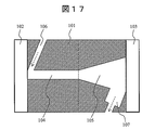
- FIG. 16 to FIG. 21 show an embodiment of a flow cell having various fluid discharge portions that enable such an effect, by a cross-sectional view at the same position as FIG.
- FIG. 16 shows an embodiment of a flow cell having a flow path having the same shape as in FIG. 5 and having a cross-sectional area of the fluid discharge part 107 that is equal to or larger than a cross-sectional area of the fluid introduction part 106.
- the ratio is equal to or greater than the ratio of the maximum cross-sectional area of the channel 105. More specifically, the diameter of the cylindrical flow path 104 is 0.3 mm or more and 1 mm or less, the total optical path length of the flow cell is 5 mm or more and 50 mm or less, and the cone angle of the truncated cone-shaped flow path 105 is 1 degree or more and 30 degrees.
- the flow path diameter of the fluid introduction part 106 is preferably 0.2 mm or more and 0.5 mm or less, and the flow path diameter of the fluid discharge part 107 is preferably 0.2 mm or more and 3.0 mm or less.
- the cross section of the fluid discharge unit 107 may be circular, elliptical, or polygonal.
- this effect can also be obtained by expanding the cross-sectional area of only a part of the channel on the side connected to the second cylindrical channel 105 in the fluid discharge unit 107.
- the cross-sectional area is expanded only to a part of the flow path of the fluid discharge section, so that connection of piping and the like are facilitated.
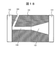
- this effect can be achieved by providing not only one fluid discharge part but also two or more.
- the total cross-sectional area of the plurality of fluid discharge portions may be larger than the cross-sectional area of the fluid introduction portion.
- FIG. 18 shows an embodiment of a flow cell having a flow path of the same shape as in FIG. 5 and having two fluid discharge portions, and shows a cross-sectional view at the same position as in FIG.
- FIG. 19 shows a view of the flow cell of this embodiment viewed from the window member 103 side, and the two fluid discharge portions 107a and 107b are arranged at positions symmetrical with respect to the axis of the flow path.
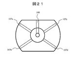
- FIG. 20 shows an embodiment of a flow cell having three flow outlets 107a to 107c having flow paths of the same shape as in FIG. 5 and arranged symmetrically with respect to the flow path axis, and FIG. FIG.
- FIG. 20 shows an embodiment of a flow cell in which fluid discharge portions 107a to 107d are arranged at positions symmetrical to each other with respect to the axis of the flow path, and is a view of the flow cell viewed from the same direction as FIG. 18 to 21, specifically, the diameter of the cylindrical channel 104 is 0.3 mm or more and 1 mm or less, the total optical path length of the flow cell is 5 mm or more and 50 mm or less, and the cone angle of the frustoconical channel 105 is 1.
- the flow path diameter of the fluid introduction part 106 and each fluid discharge part 107 is preferably 0.2 mm or more and 3.0 mm or less.
- the structure for increasing the fluid replacement efficiency mentioned above is based on the flow path structure shown in FIG. 5, but based on the flow path structure shown in FIGS. 8 to 12, 14, and 15.
- the same effect can be obtained.
- the same effect can be obtained even if the cross-sectional area of the fluid discharge portion is made larger than the cross-sectional area of the fluid introduction portion based on the cylindrical flow passage or the flow passage having the whole flow passage tapered.
- the flow channel structure of FIG. 5 or FIG. 11 is used. It is desirable to make it.
- the flow cell according to the present invention is incorporated in a liquid analyzer represented by flow injection analysis, liquid chromatography, or the like, and is used for spectroscopic analysis of a sample by light absorption or light emission.
- FIG. 22 to FIG. 24 are explanatory diagrams when the flow cell according to the present invention is incorporated in a liquid analyzer.
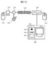
- FIG. 22 shows a flow path system of the liquid chromatograph apparatus.
- the eluent is sent from the eluent tank 2201 by the pump 2202 and supplied to the separation column 2204 through the sample introduction unit 2203.
- a sample containing a test component is introduced from an injector 2205, separated by a separation column 2204, passed through a spectrophotometer 2206, and discharged into a waste liquid tank 2207.
- the spectrophotometer 2206 is connected to the control unit 2208.
- the control unit 2208 for example, a personal computer (PC) as shown in FIG. 22 can be used.
- the PC includes a data display device 2209 and a data processing device 2210.
- the data processing device 2210 includes, for example, an arithmetic device 2211, a temporary storage device 2212, and a nonvolatile storage device 2213.
- FIG. 23 shows an optical system capable of single wavelength detection of the spectrophotometer 2206 in FIG.
- the flow cell 100 has the structure shown in FIG. 17, and has a light incident window 102 at one end of the flow cell body 101 and a light exit window 103 at the other end.
- the light from the light source 2301 passes through the condensing mirror 2302, and then is dispersed by the diffraction grating 2303, and a specific monochromatic light is irradiated to the first cylindrical flow path 104 in the flow cell 100 fixed by the jig 2304. .
- the solution containing the separated sample eluted from the separation column 2204 is supplied from the fluid introduction unit 106 to the flow cell 100, passes through the first cylindrical channel 104 and the second cylindrical channel 105, and then the fluid discharge unit. 107 is discharged.
- the light transmitted through the first cylindrical channel 104 and the second cylindrical channel 105 is received by the photodetector 2306, and the received light signal is converted into absorbance by the detection circuit 2307 connected to the control unit 2308.
- the As the light source 2301 an arbitrary light source that can provide light in an appropriate band including a deuterium lamp or a halogen lamp is used.
- the photodetector 2306 a photodetector capable of detecting single wavelength light such as a silicon photodiode is used. In order to enhance the effect of the present invention, the optical system was adjusted so that the focus position of the measurement light emitted from the light source was set on the fluid introduction side rather than the fluid discharge side of the first cylindrical channel 104.
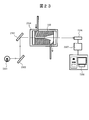
- FIG. 24 is a schematic diagram showing an optical system capable of multi-wavelength detection, which is an example of a liquid analyzer having another form of spectrophotometer.
- the flow cell 100 has the same configuration as that shown in FIG. 17, and has a light entrance window 102 at one end of the flow cell body 101 and a light exit window 103 at the other end.
- the light from the light source 2401 passes through the condensing mirror 2402 and then irradiates the first cylindrical flow path 104 in the flow cell 100 fixed by the jig 2403.
- the solution containing the separated sample eluted from the separation column 2204 is supplied to the flow cell 100 from the fluid introduction unit 106, passes through the first cylindrical channel 104 and the second cylindrical channel 105, and then the fluid discharge unit.
- the light transmitted through the first cylindrical flow path 104 and the second cylindrical flow path 105 passes through the condenser mirror 2405 and then is received by the photodetector 2407 via the diffraction grating 2406. It is converted into absorbance by a detection circuit 2408 connected to the control unit 2409.
- the light source 2401 an arbitrary light source that can provide light in an appropriate band including a deuterium lamp or a halogen lamp is used.
- the photodetector 2407 a photodetector capable of detecting multiple wavelengths such as a photodiode array is used.
- the optical system was adjusted, and the focal position of the measurement light emitted from the light source was arranged on the fluid introduction side rather than the fluid discharge side of the first cylindrical channel 104.
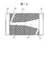
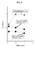
- FIG. 25 shows experimental results comparing the band expansion of the flow cell based on the present invention and the flow cell having the conventional frustoconical channel structure.
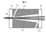
- the flow cell according to the present invention the flow cell shown in FIGS. 5 and 17 was used. Further, as a comparative example, the flow cell having the conventional truncated cone cylindrical structure shown in FIG.
- the diameter of the light incident end of the frustoconical channel 1007 shown in FIG. 3 is the same as the diameter of the light incident end of the first cylindrical channel 104 shown in FIGS.
- the diameter of the light exit end is the same as the diameter of the light exit end of the second frustoconical channel 105 shown in FIGS.
- the eluent is methanol
- the flow rate is 1 mL / min
- the measurement wavelength is 250 nm
- a benzene 0.01% methanol solution is added to the sample.
- the band expansion of each flow cell was measured.
- the band spread of each flow cell was expressed as a relative value, assuming that the band spread at the flow rate of the flow cell of the comparative example was 0.5 mL / min.
- the band expansion of the flow cell of the embodiment shown in FIG. 5 is smaller than that of the comparative flow cell having a frustoconical channel structure designed to have the same sensitivity. It was.
- the conventional cylindrical flow path is changed to a flow path structure including a first cylindrical flow path and a second cylindrical flow path, and the second cylindrical flow path is perpendicular to the incident optical axis.
- the cross-sectional area is constant or increases continuously in the traveling direction of incident light, and the cross-sectional area perpendicular to the incident optical axis at the light exit end of the first cylindrical flow path is the second cylindrical flow.
- FIG. 25 in addition to the flow channel structure of FIG. 5 as shown in FIG. 17, if a flow cell having a fluid discharge section with a large cross-sectional area is used, the time for the sample to stay in the flow channel is reduced, and the band is expanded. It was found that can be further reduced. Further, instead of the flow cell shown in FIG. 17, the flow cell shown in FIG. 16 and the flow cell having a plurality of fluid discharge portions shown in FIGS. As a result, it was confirmed that the same effect as the flow cell shown in FIG. 17 was obtained.
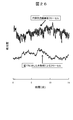
- FIG. 26 shows the experimental results of noise comparison between the flow cell according to the present invention and the flow cell having the cylindrical flow channel structure of the comparative example.
- the flow cell shown in FIG. 17 was used as the flow cell according to the present invention.
- a flow cell having the conventional cylindrical flow channel shown in FIG. 2 designed so that the optical path length and the band spread are the same was used as a comparative example. That is, a flow cell in which the diameter of the cylindrical channel 1004 shown in FIG. 2 is the same as the diameter of the light incident end of the first cylindrical channel 104 shown in FIG. 17 was used.
- the eluent was methanol, and noise at a wavelength of 250 nm at a flow rate of 1 mL / min was examined using each flow cell.
- the flow cell according to the present invention has a reduced noise due to the reduced amount of light hitting the inner wall of the flow path as compared with the flow cell having the cylindrical flow path structure of the comparative example.
- experiments were performed under the same conditions using the flow cell according to the present invention shown in FIGS. 5, 8 to 12, 14 to 16, and 18 to 21. However, the same effect was confirmed. Therefore, it has been confirmed by experiments that the use of the flow path structure shown in the present invention can achieve both reduction in the position expansion of the sample and improvement in sensitivity.
- FIGS. 25 and 26 are similar to those obtained when the experiment was performed under the same conditions using the liquid chromatography apparatus shown in FIG. 22 having the spectrophotometer shown in FIG. It was confirmed that it was obtained.
- this invention is not limited to the above-mentioned Example, Various modifications are included.
- the above-described embodiments have been described in detail for easy understanding of the present invention, and are not necessarily limited to those having all the configurations described.
- a part of the configuration of one embodiment can be replaced with the configuration of another embodiment, and the configuration of another embodiment can be added to the configuration of one embodiment.
Landscapes
- Physics & Mathematics (AREA)
- Biochemistry (AREA)
- Health & Medical Sciences (AREA)
- Life Sciences & Earth Sciences (AREA)
- Chemical & Material Sciences (AREA)
- Analytical Chemistry (AREA)
- General Health & Medical Sciences (AREA)
- General Physics & Mathematics (AREA)
- Immunology (AREA)
- Pathology (AREA)
- Spectroscopy & Molecular Physics (AREA)
- Optical Measuring Cells (AREA)
- Investigating Or Analysing Materials By Optical Means (AREA)
Applications Claiming Priority (2)
| Application Number | Priority Date | Filing Date | Title |
|---|---|---|---|
| JP2011-085740 | 2011-04-07 | ||
| JP2011085740A JP5854621B2 (ja) | 2011-04-07 | 2011-04-07 | 長光路長フローセル |
Publications (1)
| Publication Number | Publication Date |
|---|---|
| WO2012137750A1 true WO2012137750A1 (ja) | 2012-10-11 |
Family
ID=46969148
Family Applications (1)
| Application Number | Title | Priority Date | Filing Date |
|---|---|---|---|
| PCT/JP2012/059024 Ceased WO2012137750A1 (ja) | 2011-04-07 | 2012-04-03 | 長光路長フローセル |
Country Status (2)
| Country | Link |
|---|---|
| JP (1) | JP5854621B2 (enExample) |
| WO (1) | WO2012137750A1 (enExample) |
Cited By (4)
| Publication number | Priority date | Publication date | Assignee | Title |
|---|---|---|---|---|
| WO2018065208A1 (en) * | 2016-10-07 | 2018-04-12 | Biosurfit, S.A. | Detection chamber |
| WO2019228686A1 (en) * | 2018-06-01 | 2019-12-05 | T. E. Laboratories Ltd. | Portable flow cell detector comprising a uv-led emitting at 235 nm |
| JP2022511149A (ja) * | 2019-01-02 | 2022-01-31 | エム アンド ジェイ サイエンティフィック エルエルシー | 光散乱検出器及び光散乱検出器のサンプルセル |
| US11674880B2 (en) | 2019-01-02 | 2023-06-13 | M & J Scientific, Llc | Methods of determining radius of gyration of a particle using light scattering detectors |
Families Citing this family (7)
| Publication number | Priority date | Publication date | Assignee | Title |
|---|---|---|---|---|
| JP6236736B2 (ja) * | 2013-07-29 | 2017-11-29 | 三菱ケミカル株式会社 | 製膜原液の異常検知装置及び異常検知方法 |
| JP6062837B2 (ja) * | 2013-09-30 | 2017-01-18 | 株式会社日立ハイテクノロジーズ | 液体クロマトグラフ用検出器 |
| JPWO2016047701A1 (ja) * | 2014-09-26 | 2017-07-06 | 神栄テクノロジー株式会社 | 濃度測定用セル |
| US11175218B2 (en) | 2017-04-21 | 2021-11-16 | Shimadzu Corporation | Flow cell and detector equipped with the flow cell |
| US20220091036A1 (en) * | 2018-10-05 | 2022-03-24 | Provigate Inc. | Trace substance optical measuring instrument and measuring method |
| WO2020100242A1 (ja) * | 2018-11-14 | 2020-05-22 | 株式会社島津製作所 | クロマトグラフィ検出器用フローセル、クロマトグラフィ検出器およびクロマトグラフ装置 |
| WO2021024360A1 (ja) * | 2019-08-05 | 2021-02-11 | 株式会社島津製作所 | 液体クロマトグラフ用検出器 |
Citations (6)
| Publication number | Priority date | Publication date | Assignee | Title |
|---|---|---|---|---|
| JPS63198867A (ja) * | 1987-02-14 | 1988-08-17 | Shimadzu Corp | アレイ型分光光度計検出器 |
| JPH0662355U (ja) * | 1993-01-29 | 1994-09-02 | 株式会社島津製作所 | 長光路長フロ−セル測定装置 |
| JPH078759U (ja) * | 1993-07-09 | 1995-02-07 | 日本分光株式会社 | 流体試料用フローセル |
| JPH09170981A (ja) * | 1995-09-06 | 1997-06-30 | Hewlett Packard Co <Hp> | 少量のサンプル体積のための光測定式フロー装置 |
| JPH11166886A (ja) * | 1997-12-04 | 1999-06-22 | Hitachi Ltd | 液体クロマトグラフ装置 |
| JP2009544016A (ja) * | 2006-07-20 | 2009-12-10 | トリネアン・ナムローゼ・フェンノートシャップ | 光学的キャラクタリゼーション法およびシステム |
Family Cites Families (4)
| Publication number | Priority date | Publication date | Assignee | Title |
|---|---|---|---|---|
| CA1050298A (en) * | 1974-05-15 | 1979-03-13 | Kenneth E. Nelson | Photometric system with conical flow cell |
| JPS6215439A (ja) * | 1985-07-13 | 1987-01-23 | Shimadzu Corp | 吸光光度定量用フロ−セル |
| JPH08129003A (ja) * | 1994-10-31 | 1996-05-21 | Shimadzu Corp | 紫外可視分光光度計検出器 |
| JPH11168886A (ja) * | 1997-12-03 | 1999-06-22 | Toshiba Corp | 電源装置 |
-
2011
- 2011-04-07 JP JP2011085740A patent/JP5854621B2/ja not_active Expired - Fee Related
-
2012
- 2012-04-03 WO PCT/JP2012/059024 patent/WO2012137750A1/ja not_active Ceased
Patent Citations (6)
| Publication number | Priority date | Publication date | Assignee | Title |
|---|---|---|---|---|
| JPS63198867A (ja) * | 1987-02-14 | 1988-08-17 | Shimadzu Corp | アレイ型分光光度計検出器 |
| JPH0662355U (ja) * | 1993-01-29 | 1994-09-02 | 株式会社島津製作所 | 長光路長フロ−セル測定装置 |
| JPH078759U (ja) * | 1993-07-09 | 1995-02-07 | 日本分光株式会社 | 流体試料用フローセル |
| JPH09170981A (ja) * | 1995-09-06 | 1997-06-30 | Hewlett Packard Co <Hp> | 少量のサンプル体積のための光測定式フロー装置 |
| JPH11166886A (ja) * | 1997-12-04 | 1999-06-22 | Hitachi Ltd | 液体クロマトグラフ装置 |
| JP2009544016A (ja) * | 2006-07-20 | 2009-12-10 | トリネアン・ナムローゼ・フェンノートシャップ | 光学的キャラクタリゼーション法およびシステム |
Cited By (12)
| Publication number | Priority date | Publication date | Assignee | Title |
|---|---|---|---|---|
| WO2018065208A1 (en) * | 2016-10-07 | 2018-04-12 | Biosurfit, S.A. | Detection chamber |
| WO2019228686A1 (en) * | 2018-06-01 | 2019-12-05 | T. E. Laboratories Ltd. | Portable flow cell detector comprising a uv-led emitting at 235 nm |
| CN112219106A (zh) * | 2018-06-01 | 2021-01-12 | T.E.实验室有限公司 | 包括发射235nm光的UV-LED的便携式流动池检测器 |
| CN112219106B (zh) * | 2018-06-01 | 2024-04-09 | 水质监测有限公司 | 包括发射235nm光的UV-LED的便携式流动池检测器 |
| US12013335B2 (en) | 2018-06-01 | 2024-06-18 | Aquamonitrix Limited | Portable flow cell detector comprising a UV-LED emitting at 235 nm |
| JP2022511149A (ja) * | 2019-01-02 | 2022-01-31 | エム アンド ジェイ サイエンティフィック エルエルシー | 光散乱検出器及び光散乱検出器のサンプルセル |
| KR20220031754A (ko) * | 2019-01-02 | 2022-03-11 | 엠 앤 제이 사이언티픽, 엘엘씨 | 광 산란 검출기 및 광 산란 검출기용 샘플 셀 |
| US11674880B2 (en) | 2019-01-02 | 2023-06-13 | M & J Scientific, Llc | Methods of determining radius of gyration of a particle using light scattering detectors |
| JP7307495B2 (ja) | 2019-01-02 | 2023-07-12 | エム アンド ジェイ サイエンティフィック エルエルシー | 光散乱検出器及び光散乱検出器のサンプルセル |
| US12019007B2 (en) | 2019-01-02 | 2024-06-25 | Tosoh Corporation | Light scattering detectors and methods for the same |
| US12019016B2 (en) | 2019-01-02 | 2024-06-25 | Tosoh Corporation | Light scattering detectors and sample cells for the same |
| KR102730340B1 (ko) * | 2019-01-02 | 2024-11-15 | 도소 가부시키가이샤 | 광 산란 검출기 및 광 산란 검출기용 샘플 셀 |
Also Published As
| Publication number | Publication date |
|---|---|
| JP5854621B2 (ja) | 2016-02-09 |
| JP2012220324A (ja) | 2012-11-12 |
Similar Documents
| Publication | Publication Date | Title |
|---|---|---|
| JP5854621B2 (ja) | 長光路長フローセル | |
| US7982875B2 (en) | Method and apparatus for measuring the scattered light signals from a liquid sample | |
| US6281975B1 (en) | Capillary flow cell with bulbous ends | |
| US9658153B2 (en) | Flow cell and liquid analyzer | |
| US4011451A (en) | Novel photometric system | |
| EP2180306B1 (en) | Focussing arrangement for a capillary cell | |
| CN102713564A (zh) | 光学流通池检测器 | |
| JPH09170981A (ja) | 少量のサンプル体積のための光測定式フロー装置 | |
| US5434664A (en) | Capillary flowcell for multiple wavelength detection | |
| EP0717839A1 (en) | A high efficiency fluorescence flow cell | |
| US4276475A (en) | Novel photometric system | |
| US20220268628A1 (en) | Devices, systems, and methods for spectroscopy having an adjustable pathlength | |
| JP2012220324A5 (enExample) | ||
| CN107532992A (zh) | 光学测定装置 | |
| JP2013088367A (ja) | 試料セル及び分光光度計 | |
| JPH03179240A (ja) | 液体の吸光度を測定する装置 | |
| JP5915451B2 (ja) | フローセル | |
| CN102680093A (zh) | 多用途分光光度计 | |
| CN110531013A (zh) | 一种利用毛细管管壁轴向全反射的检测池 | |
| US20180335408A1 (en) | Combined fluorescence and absorption detector for on-column detection after capillary separation techniques | |
| JP7147952B2 (ja) | クロマトグラフ用検出器 | |
| JP2002148182A (ja) | フローセル | |
| JP7180760B2 (ja) | クロマトグラフィ検出器用フローセルおよびクロマトグラフィ検出器 | |
| US20200200720A1 (en) | Optical detector flow cell for co2-based chromatography | |
| US20070076204A1 (en) | Optical detection device with reduced light throughput oscillations |
Legal Events
| Date | Code | Title | Description |
|---|---|---|---|
| 121 | Ep: the epo has been informed by wipo that ep was designated in this application |
Ref document number: 12767491 Country of ref document: EP Kind code of ref document: A1 |
|
| NENP | Non-entry into the national phase |
Ref country code: DE |
|
| 122 | Ep: pct application non-entry in european phase |
Ref document number: 12767491 Country of ref document: EP Kind code of ref document: A1 |