WO2012137559A1 - フレキシブル粘土膜とその製造方法およびそれを用いたフレキシブル基板 - Google Patents
フレキシブル粘土膜とその製造方法およびそれを用いたフレキシブル基板 Download PDFInfo
- Publication number
- WO2012137559A1 WO2012137559A1 PCT/JP2012/054886 JP2012054886W WO2012137559A1 WO 2012137559 A1 WO2012137559 A1 WO 2012137559A1 JP 2012054886 W JP2012054886 W JP 2012054886W WO 2012137559 A1 WO2012137559 A1 WO 2012137559A1
- Authority
- WO
- WIPO (PCT)
- Prior art keywords
- clay
- aggregate
- flexible
- film
- clay film
- Prior art date
- Legal status (The legal status is an assumption and is not a legal conclusion. Google has not performed a legal analysis and makes no representation as to the accuracy of the status listed.)
- Ceased
Links
Images



Classifications
-
- H—ELECTRICITY
- H05—ELECTRIC TECHNIQUES NOT OTHERWISE PROVIDED FOR
- H05K—PRINTED CIRCUITS; CASINGS OR CONSTRUCTIONAL DETAILS OF ELECTRIC APPARATUS; MANUFACTURE OF ASSEMBLAGES OF ELECTRICAL COMPONENTS
- H05K1/00—Printed circuits
- H05K1/02—Details
- H05K1/03—Use of materials for the substrate
- H05K1/0393—Flexible materials
-
- B—PERFORMING OPERATIONS; TRANSPORTING
- B32—LAYERED PRODUCTS
- B32B—LAYERED PRODUCTS, i.e. PRODUCTS BUILT-UP OF STRATA OF FLAT OR NON-FLAT, e.g. CELLULAR OR HONEYCOMB, FORM
- B32B13/00—Layered products comprising a a layer of water-setting substance, e.g. concrete, plaster, asbestos cement, or like builders' material
- B32B13/04—Layered products comprising a a layer of water-setting substance, e.g. concrete, plaster, asbestos cement, or like builders' material comprising such water setting substance as the main or only constituent of a layer, which is next to another layer of the same or of a different material
- B32B13/06—Layered products comprising a a layer of water-setting substance, e.g. concrete, plaster, asbestos cement, or like builders' material comprising such water setting substance as the main or only constituent of a layer, which is next to another layer of the same or of a different material of metal
-
- B—PERFORMING OPERATIONS; TRANSPORTING
- B32—LAYERED PRODUCTS
- B32B—LAYERED PRODUCTS, i.e. PRODUCTS BUILT-UP OF STRATA OF FLAT OR NON-FLAT, e.g. CELLULAR OR HONEYCOMB, FORM
- B32B15/00—Layered products comprising a layer of metal
- B32B15/02—Layer formed of wires, e.g. mesh
-
- C—CHEMISTRY; METALLURGY
- C01—INORGANIC CHEMISTRY
- C01B—NON-METALLIC ELEMENTS; COMPOUNDS THEREOF; METALLOIDS OR COMPOUNDS THEREOF NOT COVERED BY SUBCLASS C01C
- C01B33/00—Silicon; Compounds thereof
- C01B33/20—Silicates
- C01B33/36—Silicates having base-exchange properties but not having molecular sieve properties
- C01B33/38—Layered base-exchange silicates, e.g. clays, micas or alkali metal silicates of kenyaite or magadiite type
- C01B33/40—Clays
-
- C—CHEMISTRY; METALLURGY
- C04—CEMENTS; CONCRETE; ARTIFICIAL STONE; CERAMICS; REFRACTORIES
- C04B—LIME, MAGNESIA; SLAG; CEMENTS; COMPOSITIONS THEREOF, e.g. MORTARS, CONCRETE OR LIKE BUILDING MATERIALS; ARTIFICIAL STONE; CERAMICS; REFRACTORIES; TREATMENT OF NATURAL STONE
- C04B28/00—Compositions of mortars, concrete or artificial stone, containing inorganic binders or the reaction product of an inorganic and an organic binder, e.g. polycarboxylate cements
- C04B28/001—Compositions of mortars, concrete or artificial stone, containing inorganic binders or the reaction product of an inorganic and an organic binder, e.g. polycarboxylate cements containing unburned clay
-
- C—CHEMISTRY; METALLURGY
- C04—CEMENTS; CONCRETE; ARTIFICIAL STONE; CERAMICS; REFRACTORIES
- C04B—LIME, MAGNESIA; SLAG; CEMENTS; COMPOSITIONS THEREOF, e.g. MORTARS, CONCRETE OR LIKE BUILDING MATERIALS; ARTIFICIAL STONE; CERAMICS; REFRACTORIES; TREATMENT OF NATURAL STONE
- C04B33/00—Clay-wares
- C04B33/36—Reinforced clay-wares
-
- C—CHEMISTRY; METALLURGY
- C04—CEMENTS; CONCRETE; ARTIFICIAL STONE; CERAMICS; REFRACTORIES
- C04B—LIME, MAGNESIA; SLAG; CEMENTS; COMPOSITIONS THEREOF, e.g. MORTARS, CONCRETE OR LIKE BUILDING MATERIALS; ARTIFICIAL STONE; CERAMICS; REFRACTORIES; TREATMENT OF NATURAL STONE
- C04B35/00—Shaped ceramic products characterised by their composition; Ceramics compositions; Processing powders of inorganic compounds preparatory to the manufacturing of ceramic products
- C04B35/622—Forming processes; Processing powders of inorganic compounds preparatory to the manufacturing of ceramic products
- C04B35/62218—Forming processes; Processing powders of inorganic compounds preparatory to the manufacturing of ceramic products obtaining ceramic films, e.g. by using temporary supports
-
- H—ELECTRICITY
- H05—ELECTRIC TECHNIQUES NOT OTHERWISE PROVIDED FOR
- H05K—PRINTED CIRCUITS; CASINGS OR CONSTRUCTIONAL DETAILS OF ELECTRIC APPARATUS; MANUFACTURE OF ASSEMBLAGES OF ELECTRICAL COMPONENTS
- H05K1/00—Printed circuits
- H05K1/02—Details
- H05K1/03—Use of materials for the substrate
- H05K1/0313—Organic insulating material
- H05K1/0353—Organic insulating material consisting of two or more materials, e.g. two or more polymers, polymer + filler, + reinforcement
- H05K1/0366—Organic insulating material consisting of two or more materials, e.g. two or more polymers, polymer + filler, + reinforcement reinforced, e.g. by fibres, fabrics
-
- B—PERFORMING OPERATIONS; TRANSPORTING
- B32—LAYERED PRODUCTS
- B32B—LAYERED PRODUCTS, i.e. PRODUCTS BUILT-UP OF STRATA OF FLAT OR NON-FLAT, e.g. CELLULAR OR HONEYCOMB, FORM
- B32B2307/00—Properties of the layers or laminate
- B32B2307/50—Properties of the layers or laminate having particular mechanical properties
-
- B—PERFORMING OPERATIONS; TRANSPORTING
- B32—LAYERED PRODUCTS
- B32B—LAYERED PRODUCTS, i.e. PRODUCTS BUILT-UP OF STRATA OF FLAT OR NON-FLAT, e.g. CELLULAR OR HONEYCOMB, FORM
- B32B2457/00—Electrical equipment
-
- C—CHEMISTRY; METALLURGY
- C04—CEMENTS; CONCRETE; ARTIFICIAL STONE; CERAMICS; REFRACTORIES
- C04B—LIME, MAGNESIA; SLAG; CEMENTS; COMPOSITIONS THEREOF, e.g. MORTARS, CONCRETE OR LIKE BUILDING MATERIALS; ARTIFICIAL STONE; CERAMICS; REFRACTORIES; TREATMENT OF NATURAL STONE
- C04B2111/00—Mortars, concrete or artificial stone or mixtures to prepare them, characterised by specific function, property or use
- C04B2111/00241—Physical properties of the materials not provided for elsewhere in C04B2111/00
- C04B2111/00318—Materials characterised by relatively small dimensions, e.g. small thickness
-
- C—CHEMISTRY; METALLURGY
- C04—CEMENTS; CONCRETE; ARTIFICIAL STONE; CERAMICS; REFRACTORIES
- C04B—LIME, MAGNESIA; SLAG; CEMENTS; COMPOSITIONS THEREOF, e.g. MORTARS, CONCRETE OR LIKE BUILDING MATERIALS; ARTIFICIAL STONE; CERAMICS; REFRACTORIES; TREATMENT OF NATURAL STONE
- C04B2111/00—Mortars, concrete or artificial stone or mixtures to prepare them, characterised by specific function, property or use
- C04B2111/00474—Uses not provided for elsewhere in C04B2111/00
- C04B2111/00844—Uses not provided for elsewhere in C04B2111/00 for electronic applications
-
- C—CHEMISTRY; METALLURGY
- C04—CEMENTS; CONCRETE; ARTIFICIAL STONE; CERAMICS; REFRACTORIES
- C04B—LIME, MAGNESIA; SLAG; CEMENTS; COMPOSITIONS THEREOF, e.g. MORTARS, CONCRETE OR LIKE BUILDING MATERIALS; ARTIFICIAL STONE; CERAMICS; REFRACTORIES; TREATMENT OF NATURAL STONE
- C04B2235/00—Aspects relating to ceramic starting mixtures or sintered ceramic products
- C04B2235/02—Composition of constituents of the starting material or of secondary phases of the final product
- C04B2235/50—Constituents or additives of the starting mixture chosen for their shape or used because of their shape or their physical appearance
- C04B2235/52—Constituents or additives characterised by their shapes
- C04B2235/5208—Fibers
- C04B2235/5252—Fibers having a specific pre-form
- C04B2235/5256—Two-dimensional, e.g. woven structures
-
- C—CHEMISTRY; METALLURGY
- C04—CEMENTS; CONCRETE; ARTIFICIAL STONE; CERAMICS; REFRACTORIES
- C04B—LIME, MAGNESIA; SLAG; CEMENTS; COMPOSITIONS THEREOF, e.g. MORTARS, CONCRETE OR LIKE BUILDING MATERIALS; ARTIFICIAL STONE; CERAMICS; REFRACTORIES; TREATMENT OF NATURAL STONE
- C04B2235/00—Aspects relating to ceramic starting mixtures or sintered ceramic products
- C04B2235/70—Aspects relating to sintered or melt-casted ceramic products
- C04B2235/94—Products characterised by their shape
-
- H—ELECTRICITY
- H05—ELECTRIC TECHNIQUES NOT OTHERWISE PROVIDED FOR
- H05K—PRINTED CIRCUITS; CASINGS OR CONSTRUCTIONAL DETAILS OF ELECTRIC APPARATUS; MANUFACTURE OF ASSEMBLAGES OF ELECTRICAL COMPONENTS
- H05K1/00—Printed circuits
- H05K1/02—Details
- H05K1/03—Use of materials for the substrate
- H05K1/0313—Organic insulating material
- H05K1/0353—Organic insulating material consisting of two or more materials, e.g. two or more polymers, polymer + filler, + reinforcement
- H05K1/0373—Organic insulating material consisting of two or more materials, e.g. two or more polymers, polymer + filler, + reinforcement containing additives, e.g. fillers
-
- H—ELECTRICITY
- H05—ELECTRIC TECHNIQUES NOT OTHERWISE PROVIDED FOR
- H05K—PRINTED CIRCUITS; CASINGS OR CONSTRUCTIONAL DETAILS OF ELECTRIC APPARATUS; MANUFACTURE OF ASSEMBLAGES OF ELECTRICAL COMPONENTS
- H05K2201/00—Indexing scheme relating to printed circuits covered by H05K1/00
- H05K2201/02—Fillers; Particles; Fibers; Reinforcement materials
- H05K2201/0203—Fillers and particles
- H05K2201/0206—Materials
- H05K2201/0209—Inorganic, non-metallic particles
-
- H—ELECTRICITY
- H05—ELECTRIC TECHNIQUES NOT OTHERWISE PROVIDED FOR
- H05K—PRINTED CIRCUITS; CASINGS OR CONSTRUCTIONAL DETAILS OF ELECTRIC APPARATUS; MANUFACTURE OF ASSEMBLAGES OF ELECTRICAL COMPONENTS
- H05K2201/00—Indexing scheme relating to printed circuits covered by H05K1/00
- H05K2201/02—Fillers; Particles; Fibers; Reinforcement materials
- H05K2201/0203—Fillers and particles
- H05K2201/0242—Shape of an individual particle
- H05K2201/0245—Flakes, flat particles or lamellar particles
-
- H—ELECTRICITY
- H05—ELECTRIC TECHNIQUES NOT OTHERWISE PROVIDED FOR
- H05K—PRINTED CIRCUITS; CASINGS OR CONSTRUCTIONAL DETAILS OF ELECTRIC APPARATUS; MANUFACTURE OF ASSEMBLAGES OF ELECTRICAL COMPONENTS
- H05K2201/00—Indexing scheme relating to printed circuits covered by H05K1/00
- H05K2201/20—Details of printed circuits not provided for in H05K2201/01 - H05K2201/10
- H05K2201/2072—Anchoring, i.e. one structure gripping into another
Definitions
- the present invention relates to a flexible clay film, a method for producing the same, and a flexible substrate using the same, and in particular, for example, a flexible clay film that can be used as a packing or a thin-film electronic substrate, a method for producing the same, and a flexible substrate using the same.
- a flexible clay film that can be used as a packing or a thin-film electronic substrate, a method for producing the same, and a flexible substrate using the same.
- a clay self-supporting film having a structure in which clay particles are oriented and laminated has been developed as a clay film used as a material for packing used in piping connection parts of various production lines.
- a clay film has characteristics such as having mechanical strength as a self-supporting film, high gas barrier properties (low gas permeability), high heat resistance, and excellent flexibility.
- the clay free-standing film is formed, for example, by dispersing clay in a dispersion medium, depositing clay particles, and solid-liquid separation (see Patent Document 1).
- the clay film has a mechanical strength as a free-standing film and is excellent in flexibility. There is a problem that it is brittle.
- the clay film has a laminated structure of flat particles having a high aspect ratio, and when the clay film is folded in one direction, the particles are slid to provide flexibility. .
- the particles do not slip in one direction, and stress concentrates, so that the clay film is cracked.
- Patent Documents 2 and 3 show examples in which mineral fibers, glass wool, ceramic fibers, and the like are used as reinforcing materials for increasing the mechanical strength as a self-supporting film. However, it has been shown that these reinforcing materials are added in a proportion of 30% by weight or less in order to ensure the uniformity of the distribution of the reinforcing material and the clay. Therefore, it is considered that the reinforcing material here is used in a state where a plurality of fine fibers are uniformly dispersed in the clay film.
- the techniques disclosed in Patent Document 2 and Patent Document 3 are for increasing the mechanical strength as a self-supporting film, and even if these techniques are used, the strength against twist cannot be increased.
- Patent Document 3 discloses a multilayer film composed of a cloth and a clay layer. However, in this configuration, when the twist is applied, the cloth and the clay layer are peeled off, so that the strength against the twist cannot be increased.
- a main object of the present invention is to provide a flexible clay film having excellent flexibility and high strength against twisting, a manufacturing method thereof, and a flexible substrate using the same.
- the present invention includes a clay film in which clay particles are oriented and laminated, and a sheet-like aggregate having a mesh-like opening, and the outer edge of the aggregate is the same as or outside the outer edge of the clay film.
- a flexible clay film in which the opening of the aggregate is filled with a clay film.
- strength with respect to a twist is obtained by integrating the aggregate and clay film with a large intensity
- the thickness of the aggregate is preferably 70 ⁇ m or more and 150 ⁇ m or less.
- the thickness of the aggregate is preferably 70 ⁇ m or more and 150 ⁇ m or less.
- the thickness of the aggregate is 70 ⁇ m or more, the strength of the aggregate itself is high, and the strength against twisting is further increased.
- the thickness of the aggregate is 150 ⁇ m or less, the aggregate is easily deformed when force is applied to the aggregate, and the flexibility is excellent.
- the aggregate is preferably made of an inorganic material.
- Aggregates made of an inorganic material have a high strength against twisting, and can obtain excellent heat resistance.
- the inorganic material is preferably a metal.
- the inorganic material is preferably a metal.
- the aggregate is formed by forming an opening in a single plate material.
- an opening is formed on a single plate material, there is no weave like a wire mesh knitted with a metal wire, and there is no unevenness on the surface of the aggregate. Therefore, when the aggregate and the clay film are integrated, the flatness of the clay film can be improved.
- the aggregate since the aggregate has no texture, it can be twisted in various directions. In the case of a wire mesh with a texture, stress tends to concentrate on the textured part, whereas the use of a non-textured aggregate can alleviate the stress concentration and improve the strength against twisting. it can.
- the aggregate is not exposed from the main surface of the clay film and exists in the clay film in the thickness direction.
- a flexible clay film is used as a flexible substrate such as an electronic circuit
- a circuit can be formed on the surface of the clay film where the aggregate is not exposed.
- the aggregate is made of a conductive material such as metal, it is necessary to prevent the aggregate from being exposed from the main surface of the clay film so that the electrodes formed on the surface of the clay film do not short-circuit. There is.
- the aggregate when the aggregate is formed of an insulating material, the aggregate may be exposed from the main surface of the clay film.
- a circuit can be formed by forming electrodes on the aggregate exposed surface of the flexible clay film.
- this invention is a flexible substrate using the flexible clay film in any one of the above-mentioned as an insulating layer.
- an electronic circuit that is not easily damaged by bending or twisting can be manufactured.
- the present invention is a flexible substrate using a flexible clay film in which aggregates are exposed on the main surface of the flexible clay film, wherein electrodes are formed on the surface of the flexible clay film and embedded in the flexible clay film.
- An exposed portion of the aggregate is a flexible substrate in which the inside of the electrode enters.
- the present invention also includes a step of preparing a clay slurry in which clay particles and a liquid that swells the clay particles are mixed so as to form a slurry, and a step of preparing a sheet-like aggregate having a mesh-shaped opening. And impregnating the aggregate with clay slurry to fill the aggregate openings with clay slurry; drying the clay slurry to volatilize the liquid and orienting and laminating the clay particles; Is a method for producing a flexible clay film. By impregnating the aggregate having a mesh-like opening with clay slurry, the clay particles can be oriented with the clay slurry entering the opening. Thereby, a flexible clay film in which the clay film and the aggregate are integrated can be obtained, and a flexible clay film having high strength against twisting can be obtained.
- the present invention provides a step of preparing a clay gel in which clay particles and a liquid that swells the clay particles are mixed in a gel state, and a step of preparing a sheet-like aggregate having a mesh-like opening And a step of placing the clay gel on the surface of the aggregate, a step of filling the opening of the aggregate with the clay gel by pressing the gel, and volatilizing the liquid by drying the clay gel, and the clay
- a method for producing a flexible clay film comprising a step of aligning and laminating gels.
- a clay gel may be arranged on the surface of the aggregate, and the opening of the aggregate may be filled with the clay gel by pressing the clay gel. In this state, by drying and orienting the clay gel, it is possible to obtain a flexible clay film having a high strength against shining.
- the flexible clay film having mechanical strength as a self-supporting film, excellent in flexibility, and having high strength against twisting. Furthermore, by forming a flexible substrate using this flexible clay film as an insulating layer, it is possible to obtain a flexible substrate for an electronic circuit that is not easily damaged by bending or twisting. Moreover, according to the manufacturing method of this invention, the flexible clay film which is excellent in flexibility, and has big intensity
- (A) is a top view of the flexible clay film of this invention
- (B) is the sectional drawing. It is an illustration figure which shows the structure of the flexible substrate by which the electrode was formed in the flexible clay film
- FIG. 1 (A) is a plan view showing the flexible clay film of the present invention
- FIG. 1 (B) is a sectional view thereof.
- the flexible clay film 10 includes a clay film 12. Inside the clay film 12, one aggregate 14 is disposed in the planar direction. Aggregate 14 may arrange a plurality of aggregates in the thickness direction. This is because the twist strength is further improved. However, since there is a possibility that flexibility increases when aggregates increase, it is preferable that there is only one aggregate.
- the aggregate 14 is a sheet shape which has a mesh-shaped opening part, for example. However, the shape of the opening of the aggregate 14 may be a triangle, a quadrangle, or the like, and can be an arbitrary shape.
- the flexible clay film 10 is formed by bringing one surface of the aggregate 14 into contact with the slurry for forming the clay film 12, drying the slurry, and then dispersing the clay from above with the dried slurry down.
- the clay sheets 12a and 12b are integrated so as to enter the mesh-shaped openings of the aggregate 14.
- the flexible clay film 10 in which the clay sheets 12a and 12b enter the openings of the aggregate 14 can be formed by immersing the aggregate in the slurry and performing drying while lifting the aggregate.
- the aggregate 14 is preferably arranged parallel to the main surface of the clay film 12, but may be slightly inclined.
- the outer edge of the aggregate 14, that is, the outer peripheral end is formed to be the same as the outer edge of the clay film 12, but the outer edge of the aggregate 14 is exposed.
- the outer peripheral side of the aggregate 14 may protrude from the outer edge of the clay film 12.
- a slurry is formed by uniformly dispersing clay in water. By spreading this slurry on a PET film or the like and drying it, clay sheets 12a and 12b in which clay particles are highly oriented and laminated can be obtained.
- the clay particles are oriented and laminated because the flat surfaces of the flat clay particles are spread in a direction parallel to the main surface of the clay film, and a high periodicity is obtained in a direction perpendicular to the main surface of the clay film. It means to give.
- a resin may be added to the clay sheets 12a and 12b in order to improve mechanical strength as a self-supporting film.
- the resin content of the clay sheets 12a and 12b is preferably 20% by weight or less.
- an inorganic substance may be added as necessary.
- the clay sheet has heat resistance such that the mechanical strength and flexibility as a self-supporting film do not change even when heated alone at a temperature of 300 ° C.
- the clay natural clay or synthetic clay can be used. One or more are used. For example, clay particles having a layer thickness of about 1 nm, a particle diameter of 1 ⁇ m, and an aspect ratio of about 300 are used.
- the aggregate 14 for example, an aggregate formed of an inorganic material such as a glass cloth, a wire mesh, or an expanded metal is used in order to obtain a high strength against a twist. In particular, by using the aggregate 14 formed of a metal material, it is possible to increase the strength against twisting and to obtain high thermal conductivity.
- the aggregate 14 having a flat surface such as expanded metal has a surface with irregularities such as a wire mesh knitted with a metal wire.
- the stress does not concentrate on the textured portion like the aggregate 14, and the strength against twisting can be increased.
- membrane 10 can be improved by using the aggregate 14 which has a flat surface like an expanded metal.
- the aggregate 14 formed of a metal material when used, it is preferable that the aggregate 14 is not exposed from the main surface of the clay film and exists in the clay film in the thickness direction. This is because if the metal material is exposed, insulation between the two main surfaces of the clay film cannot be secured.
- the aggregate 14 made of a metal material may be exposed from the main surface of the clay film 12 when a flexible clay film is used in a portion where insulation is not required. In this case, both surfaces of the aggregate 14 are not exposed at the same place, and the clay that has entered the opening needs to be connected to at least one main surface of the aggregate 14.
- the thickness of the aggregate 14 is preferably 70 ⁇ m or more and 150 ⁇ m or less.
- the thickness of the aggregate 14 is 70 ⁇ m or more, the strength of the aggregate itself is high, and the strength against twisting is further increased.
- the thickness of the aggregate 14 is 150 ⁇ m or less, the aggregate 14 is easily deformed when force is applied to the aggregate 14, and the flexibility is excellent.
- the flexible clay film 10 thus obtained has a structure in which the clay film 12 enters the mesh-shaped opening of the aggregate 14 and the clay film 12 and one aggregate 14 are integrated. Even if a twist is applied to the integrated clay film 12 and the aggregate 14, the aggregate itself is not strongly deformed by the force in the twisting direction, so that no great stress is generated on the clay film 12. It does n’t come. However, since the aggregate itself can be folded in one direction, the necessary flexibility is not lost. Therefore, it is possible to obtain the flexible clay film 10 having mechanical strength that is self-supporting as a clay film, excellent in flexibility, and having high strength against twisting.
- the flexible clay film 10 can be used as a flexible substrate for electronic circuits, for example.
- an insulating material is used as the material of the clay film 12, and a circuit pattern is formed on the flexible substrate where the aggregate 14 is not exposed.
- the circuit pattern is formed, for example, by laminating a Cu foil on the flexible clay film 10 formed by the method as described above, forming a resist with a photosensitive resin, etc., and performing etching and resist removal.
- an electronic circuit using such a flexible substrate can be used for, for example, a camera or a mobile phone that may be subjected to twisting stress.
- the aggregate 14 is formed from the main surface of the clay film 12. It can be set as the structure exposed.
- an insulating sheet-like or net-like material such as a glass nonwoven fabric or glass wool is used as the aggregate 14.
- the circuit pattern electrode 22 is formed on the surface of the clay film 12 where the aggregate 14 is exposed.
- the electrode 16 is formed on the clay film 12 so that the aggregate 14 exposed on the main surface of the clay film 12 enters the electrode 16.
- clay and a liquid that swells clay particles of clay are mixed in a slurry form to form a clay slurry. Further, a sheet-like aggregate 14 made of an insulating material having a mesh-like opening is prepared.
- Such an aggregate 14 is impregnated with a clay slurry using, for example, a coater, so that the opening of the aggregate 14 is filled with the clay slurry. At this time, the clay 14 is impregnated with the clay slurry so that one main surface of the aggregate 14 is exposed. Then, by drying the clay slurry, the clay particles are oriented and laminated, and the flexible clay film 10 in which the aggregate 14 is exposed on the main surface of the clay film 12 can be obtained.
- a clay gel in which clay and a liquid that swells clay particles of clay are mixed in a gel form.
- This clay gel is formed in a sheet shape and disposed on the surface of the aggregate 14 having insulation properties. Then, by pressing the clay gel toward the aggregate 14, the clay gel enters the opening of the aggregate 14, and the opening of the aggregate 14 is filled with the clay gel. Furthermore, by drying the clay gel, the clay particles are oriented and laminated to form the flexible clay film 10.
- the thickness of the clay gel to be smaller than the thickness of the aggregate 14, the flexible clay film 10 in which the aggregate 14 is exposed on the main surface of the clay film 12 can be obtained.
- the electrode 22 is formed by screen-printing and baking, for example, a conductive paste on the exposed aggregate surface of the flexible clay film 10 thus obtained.
- a conductive paste on the exposed aggregate surface of the flexible clay film 10 thus obtained.
- the conductive paste is printed, the conductive paste is entangled with the aggregate 14 exposed from the clay film 12, and the conductive paste is baked to form the electrode 22 into which the aggregate 14 has entered.
- the adhesion strength of the electrodes to the flexible clay film 10 can be improved.
- the electrode 22 is disposed on the laminated clay particles as shown in FIG.
- the adhesive force between the clay particles is weak, when the force is applied to the electrode 22, the electrode 22 is peeled from the clay film 12 while the clay particle is attached to the electrode 22.
- the aggregate 14 enters the electrode 22 as shown in FIG. Therefore, in order to peel the electrode 22 from the clay film 12, the aggregate 14 needs to be torn off. Accordingly, the adhesion strength of the electrode 22 to the clay film 12 is stronger than that of the electrode 22 formed on the clay film 12 where the aggregate 14 is not exposed.
- the aggregate 14 needs to be an insulating sheet-like or net-like material such as a glass nonwoven fabric or glass wool. This is because the contact strength of the electrode 22 is obtained by the electrode 22 being entangled with the aggregate 14, and therefore, if the conductive aggregate 14 is used, it is short-circuited and cannot be used as a circuit board.
- the method of filling the openings of the aggregate 14 with clay slurry and the method of pressing the clay gel toward the aggregate 14 are also used when the aggregate 14 using a conductive material such as a metal material is used. Can be applied.
- a conductive material such as a metal material is used.
- the electrode 22 formed on the main surface of the clay film is short-circuited. Must be placed.
- one side of the aggregate 14 is brought into contact with the clay slurry for forming the clay film 12, and the clay slurry is dried.
- the flexible clay film 10 can be formed such that the aggregate 14 is not exposed to the main surface of the clay film 12.
- the clay gel is disposed on both main surfaces of the aggregate 14, and the clay gel is pressed from both sides and dried to prevent the aggregate 14 from being exposed to the main surface of the clay film 12. Can be formed.
- the slurrying process can be simplified by pressing the high concentration gel. Furthermore, since the amount of water to be used can be greatly reduced, the drying time can be shortened, and the manufacturing cost of the flexible clay film 10 can be reduced.
- twist resistance is determined by fixing both ends in the longitudinal direction of a flexible clay film having a size of 40 mm ⁇ 60 mm and rotating the fixed part to twist the flexible clay film and twist it up to 90 °.
- “ ⁇ ” indicates that the object can be twisted up to 60 ° but cannot be twisted up to 90 °
- “ X ” indicates that the object cannot be twisted up to 60 °.
- a flexible clay film was formed by the above-described method using a metal net as an aggregate. At this time, the metal net was not exposed from the main surface of the clay film and was present inside the clay film in the thickness direction. Then, a flexible clay film was formed by changing the thickness of the metal mesh, and twist resistance and heat resistance were measured. The results are shown in Sample Nos. 6 to 9 in Table 1.
- a flexible clay film was formed by the above-described method using expanded metal as an aggregate. And about the obtained flexible clay film
- the flexible clay film can be twisted up to at least 60 ° by integrating the glass nonwoven fabric as the aggregate and the clay film.
- sample numbers 2 to 4 when the thickness of the glass nonwoven fabric is 70 ⁇ m or more and 150 ⁇ m or less, the flexible clay film can be twisted up to 90 °.
- Sample No. 1 when the thickness of the glass nonwoven fabric was less than 70 ⁇ m, when the flexible clay film was twisted by 90 °, the glass nonwoven fabric was broken and the clay film was also broken. This is thought to be because the strength of the glass nonwoven fabric is weak because the thickness of the glass nonwoven fabric is small.
- sample number 5 when the thickness of the glass nonwoven fabric exceeds 150 ⁇ m, the aggregate itself can only be twisted up to 60 ° because the aggregate is thick.
- the flexible clay film can be twisted up to at least 60 ° by integrating the wire mesh and the clay film.
- Sample No. 6 when the thickness of the wire mesh was less than 70 ⁇ m, when the flexible clay film was twisted by 90 °, the wire mesh was stretched and the clay film was broken.
- sample number 9 when the thickness of the wire mesh exceeds 150 ⁇ m, the aggregate itself can only be twisted up to 60 ° because the aggregate is thick.
- a clay slurry was spread on a PET film to obtain a clay sheet.
- a metal net was placed on the obtained clay sheet, and a clay sheet lightly moistened thereon was placed on the metal net.
- the clay sheets were stacked such that the wetted surface of the clay sheets was on the metal net side.
- a Cu foil was placed thereon, and a pressure of 200 MPa and a temperature of 60 ° C. were added.
- the obtained Cu foil laminate was heat-treated at a low oxygen partial pressure of 350 ° C. to 500 ° C. to completely remove moisture. Thereafter, a resist was formed with a photosensitive resin on the Cu foil, and an electrode pattern was formed through etching and resist removal processes.
- the obtained flexible substrate did not show dimensional deformation even at a temperature of 350 ° C. and had high mechanical strength.
- clay (Kunimine F manufactured by Kunimine Industries Co., Ltd.) was dispersed in 95 g of water to obtain a clay slurry.
- a glass nonwoven fabric having a thickness of 100 ⁇ m was placed on a PET film, and a clay slurry was poured onto the glass nonwoven fabric, which was then ground with a coater having a gap of 1.5 mm. Then, it dried at 50 degreeC for 10 hours, and peeled from PET film.
- the obtained film was heat-treated at 350 ° C. to 500 ° C. to completely remove moisture between the clay layers, thereby forming a clay film having a thickness of 100 ⁇ m.
- a glass nonwoven fabric was exposed on the main surface of the obtained clay film on the PET film side.
- a conductive paste was screen printed on the exposed glass nonwoven fabric surface of the clay film and baked to form a square electrode having a side of 2 mm.
- a glass nonwoven fabric was exposed on the main surface of the obtained clay film on the filter paper side.
- a conductive paste was screen printed on the exposed glass nonwoven fabric surface of the clay film and baked to form a square electrode having a side of 2 mm.
- an electrode peeling test was performed on a clay film not using aggregate.
- a clay slurry was prepared by dispersing 5 g of clay (Kunipia-F manufactured by Kunimine Kogyo Co., Ltd.) in 95 g of water.
- the clay slurry was poured out on the PET film, and was cut off with a coater having a gap of 1 mm, and then dried at 50 ° C. to prepare a film.
- This film was peeled off from the PET film and heat-treated at 350 ° C. to 500 ° C. to completely remove moisture between the crystal layers, thereby producing a clay film having a thickness of 60 ⁇ m.
- a conductive electrode was screen-printed on the main surface of the clay film and baked to form a square electrode having a side of 2 mm.
Landscapes
- Chemical & Material Sciences (AREA)
- Engineering & Computer Science (AREA)
- Ceramic Engineering (AREA)
- Organic Chemistry (AREA)
- Structural Engineering (AREA)
- Dispersion Chemistry (AREA)
- Inorganic Chemistry (AREA)
- Materials Engineering (AREA)
- Manufacturing & Machinery (AREA)
- Microelectronics & Electronic Packaging (AREA)
- Chemical Kinetics & Catalysis (AREA)
- Laminated Bodies (AREA)
Abstract
フレキシブル性に優れ、かつ、ひねりに対する強度が大きいフレキシブル粘土膜とその製造方法、およびそれを用いたフレキシブル基板を得る。 フレキシブル粘土膜10は、粘土膜12を含む。粘土膜12の内部には、1つの骨材14が配置され、粘土膜12と骨材14とが一体化される。骨材は、網目状の開口部を有し、この開口部に粘土膜12が入り込んで一体化される。フレキシブル粘土膜10は、電子部品のフレキシブル基板として用いることができ、このフレキシブル基板を用いた電子回路は、応力のかかる場所に設置することができる。
Description
この発明は、フレキシブル粘土膜とその製造方法およびそれを用いたフレキシブル基板に関し、特にたとえば、パッキンや薄膜状の電子基板として用いることができるフレキシブル粘土膜とその製造方法、およびそれを用いたフレキシブル基板に関する。
化学産業分野において、各種生産ラインの配管連結部に用いられるパッキンなどの材料として用いられる粘土膜として、粘土粒子が配向して積層された構造を有する粘土自立膜が開発されている。このような粘土膜は、自立膜としての機械的強度を有すること、ガスバリア性が高い(ガス透過性が低い)こと、耐熱性が高いこと、フレキシブル性に優れること、等の特徴を有している。粘土自立膜は、たとえば、粘土を分散媒に分散し、粘土粒子を沈積させて、固液分離することにより形成される(特許文献1参照)。
近年、このような粘土自立膜を電子回路などにおけるフレキシブル基板として用いることが提案されている。フレキシブル基板として用いるためには、粘土自立膜の機械的強度をさらに強化する必要がある。そこで、粘土膜に添加物や補強材を含有させることが提案されている(特許文献2参照)。
また、高い機械的強度を有する粘土自立膜を得るために、布と粘土とを多層化した粘土自立膜が提案されている(特許文献3参照)。
また、高い機械的強度を有する粘土自立膜を得るために、布と粘土とを多層化した粘土自立膜が提案されている(特許文献3参照)。
しかしながら、このような従来の粘土自立膜では、自立膜としての機械的強度を有し、フレキシブル性に優れるという特徴を備えているにもかかわらず、粘土膜をひねるような動きに対して、非常に脆いという問題がある。粘土膜は、図5に示すように、アスペクト比の高い扁平状の粒子の積層構造をとっており、粘土膜を一方方向に折り曲げるとき、粒子が滑ることにより、可撓性が得られている。しかしながら、粘土膜をひねるような力を加えると、粒子が一方方向に滑らずに、応力が集中する箇所が生じるため、粘土膜に割れが生じる。
特許文献2や特許文献3には、自立膜としての機械的強度を高めるための補強材として、鉱物繊維、グラスウール、セラミックス繊維などを用いる例が示されている。ところが、これらの補強材は、補強材と粘土の分布の均一性を確保するために、30重量%以下の割合で添加されることが示されている。よって、ここでいう補強材は、複数の微細な繊維を粘土膜中に均一に分散した状態で用いていると考えられる。このような特許文献2や特許文献3に開示された技術は、自立膜としての機械的強度を高めるためのものであり、これらの技術を用いたとしても、ひねりに対する強度を高めることはできない。また、特許文献3には、布と粘土層からなる多層膜が開示されている。しかし、この構成では、ひねりを加えたときに布と粘土層が剥離してしまうため、ひねりに対する強度を高めることはできない。
それゆえに、この発明の主たる目的は、フレキシブル性に優れ、かつ、ひねりに対する強度が大きいフレキシブル粘土膜とその製造方法、およびそれを用いたフレキシブル基板を提供することである。
この発明は、粘土粒子が配向して積層された粘土膜と、網目状の開口部を有するシート状の骨材とを含み、骨材の外縁は粘土膜の外縁と同一またはそれよりも外側にあり、骨材の開口部が粘土膜によって埋められている、フレキシブル粘土膜である。
骨材の網目状の開口部に粘土膜が入り込んで、粘土膜と骨材とが一体化することにより、粘土膜の内部に骨材が存在する構成が得られる。ここで、骨材の外縁は粘土膜の外縁と同一またはそれよりも外側にあるため、複数の小さい骨材が粘土中に分散しているのではなく、1つの骨材と粘土膜とが一体化した構成を有する。このように、粘土膜と1つの骨材とを一体化したものにひねりを加えても、骨材自身がひねる方向への力によって強く変形しないため、粘土膜に大きな応力が生じることはなく、割れには至らない。一方、骨材自身は一方方向に折り曲げが可能であるため、必要な可撓性は失われない。このように、ひねりに対する強度が大きい骨材と粘土膜とが一体化されていることにより、ひねりに対する強度が大きいフレキシブル粘土膜が得られる。
骨材の網目状の開口部に粘土膜が入り込んで、粘土膜と骨材とが一体化することにより、粘土膜の内部に骨材が存在する構成が得られる。ここで、骨材の外縁は粘土膜の外縁と同一またはそれよりも外側にあるため、複数の小さい骨材が粘土中に分散しているのではなく、1つの骨材と粘土膜とが一体化した構成を有する。このように、粘土膜と1つの骨材とを一体化したものにひねりを加えても、骨材自身がひねる方向への力によって強く変形しないため、粘土膜に大きな応力が生じることはなく、割れには至らない。一方、骨材自身は一方方向に折り曲げが可能であるため、必要な可撓性は失われない。このように、ひねりに対する強度が大きい骨材と粘土膜とが一体化されていることにより、ひねりに対する強度が大きいフレキシブル粘土膜が得られる。
このようなフレキシブル粘土膜において、骨材の厚みが70μm以上で150μm以下であることが好ましい。
フレキシブル性に優れ、かつ、ひねりに対する強度が大きいフレキシブル粘土膜を得るためには、骨材の厚みを70μm以上で150μm以下とすることが好ましい。骨材の厚みが70μm以上であると、骨材自身の強度が強く、ひねりに対する強度がより大きくなる。また、骨材の厚みが150μm以下であると、骨材に力が加わった際に、骨材が変形しやすくなり、フレキシブル性が優れる。
フレキシブル性に優れ、かつ、ひねりに対する強度が大きいフレキシブル粘土膜を得るためには、骨材の厚みを70μm以上で150μm以下とすることが好ましい。骨材の厚みが70μm以上であると、骨材自身の強度が強く、ひねりに対する強度がより大きくなる。また、骨材の厚みが150μm以下であると、骨材に力が加わった際に、骨材が変形しやすくなり、フレキシブル性が優れる。
また、骨材が無機物からなることが好ましい。
無機物からなる骨材は、ひねりに対する強度が大きく、さらに、優れた耐熱性を得ることができる。
無機物からなる骨材は、ひねりに対する強度が大きく、さらに、優れた耐熱性を得ることができる。
さらに、骨材が無機物からなるフレキシブル粘土膜において、無機物が金属であることが好ましい。
骨材を金属で作製することにより、ひねりに対する強度をさらに大きくすることができ、さらに、電磁シールド効果や高い熱伝導性を得ることができる。
骨材を金属で作製することにより、ひねりに対する強度をさらに大きくすることができ、さらに、電磁シールド効果や高い熱伝導性を得ることができる。
また、骨材は、1枚の板材に開口部を形成したものであることが好ましい。
1枚の板材に開口部を形成したものは、金属線を編んだ金網のような織り目が存在せず、骨材の面に凹凸を有しない。そのため、骨材と粘土膜とを一体化したときに、粘土膜の平坦性を向上させることができる。また、骨材に織り目がないため、様々な方向にひねりを加えることができる。織り目のある金網の場合、織り目部分に応力が集中しやすくなるのに対して、織り目のない骨材を使用することにより、応力の集中を緩和することができ、ひねりに対する強度を向上させることができる。
1枚の板材に開口部を形成したものは、金属線を編んだ金網のような織り目が存在せず、骨材の面に凹凸を有しない。そのため、骨材と粘土膜とを一体化したときに、粘土膜の平坦性を向上させることができる。また、骨材に織り目がないため、様々な方向にひねりを加えることができる。織り目のある金網の場合、織り目部分に応力が集中しやすくなるのに対して、織り目のない骨材を使用することにより、応力の集中を緩和することができ、ひねりに対する強度を向上させることができる。
また、骨材は、粘土膜の主面から露出せず厚み方向において粘土膜の内部に存在していることが好ましい。
フレキシブル粘土膜を電子回路などのフレキシブル基板として用いる場合、骨材の一部が粘土膜の主面から露出していても、骨材の露出していない粘土膜表面に回路を形成することができるが、骨材が粘土膜の主面から露出しない構成とすることにより、フレキシブル粘土膜の全面に回路を形成することができ、フレキシブル粘土膜の使用効率を向上させることができる。特に、骨材が金属などの導電性を有する材料で形成されている場合、粘土膜の表面に形成された電極がショートしないように、骨材は粘土膜の主面から露出しないようにする必要がある。
フレキシブル粘土膜を電子回路などのフレキシブル基板として用いる場合、骨材の一部が粘土膜の主面から露出していても、骨材の露出していない粘土膜表面に回路を形成することができるが、骨材が粘土膜の主面から露出しない構成とすることにより、フレキシブル粘土膜の全面に回路を形成することができ、フレキシブル粘土膜の使用効率を向上させることができる。特に、骨材が金属などの導電性を有する材料で形成されている場合、粘土膜の表面に形成された電極がショートしないように、骨材は粘土膜の主面から露出しないようにする必要がある。
ただし、骨材が絶縁性材料で形成されている場合、骨材が粘土膜の主面から露出していてもよい。この場合、フレキシブル粘土膜の骨材露出面に電極を形成して回路を形成することができる。
また、この発明は、上述のいずれかに記載のフレキシブル粘土膜を絶縁層として用いた、フレキシブル基板である。
フレキシブル粘土膜を絶縁層として用いたフレキシブル基板により、屈曲やひねりに対して破損しにくい電子回路を作製することができる。
フレキシブル粘土膜を絶縁層として用いたフレキシブル基板により、屈曲やひねりに対して破損しにくい電子回路を作製することができる。
さらに、この発明は、フレキシブル粘土膜の主面に骨材が露出したフレキシブル粘土膜を用いたフレキシブル基板であって、フレキシブル粘土膜の表面に電極が形成されており、フレキシブル粘土膜に埋められている骨材の露出部が、電極の内部に入り込んでいる、フレキシブル基板である。
フレキシブル粘土膜の表面に形成された電極の内部にフレキシブル粘土膜の主面から露出した骨材が入り込むことにより、フレキシブル粘土膜から電極を剥がすために大きい力が必要になる。そのため、フレキシブル粘土膜から電極が剥がれにくい構造を有するフレキシブル粘土基板を得ることができる。
フレキシブル粘土膜の表面に形成された電極の内部にフレキシブル粘土膜の主面から露出した骨材が入り込むことにより、フレキシブル粘土膜から電極を剥がすために大きい力が必要になる。そのため、フレキシブル粘土膜から電極が剥がれにくい構造を有するフレキシブル粘土基板を得ることができる。
また、この発明は、粘土粒子と、粘土粒子を膨潤させる液体とをスラリー状になるように混合した粘土スラリーを準備する工程と、網目状の開口部を有するシート状の骨材を準備する工程と、骨材に粘土スラリーを含浸させることにより、骨材の開口部を粘土スラリーによって埋める工程と、粘土スラリーを乾燥させることにより、液体を揮発させるとともに、粘土粒子を配向して積層させる工程とを含む、フレキシブル粘土膜の製造方法である。
網目状の開口部を有する骨材に粘土スラリーを含浸させることにより、開口部に粘土スラリーが入り込んだ状態で粘土粒子を配向させることができる。それにより、粘土膜と骨材とが一体化したフレキシブル粘土膜を得ることができ、ひねりに対する強度が大きいフレキシブル粘土膜を得ることができる。
網目状の開口部を有する骨材に粘土スラリーを含浸させることにより、開口部に粘土スラリーが入り込んだ状態で粘土粒子を配向させることができる。それにより、粘土膜と骨材とが一体化したフレキシブル粘土膜を得ることができ、ひねりに対する強度が大きいフレキシブル粘土膜を得ることができる。
さらに、この発明は、粘土粒子と、粘土粒子を膨潤させる液体とをゲル状になるように混合した粘土ゲルを準備する工程と、網目状の開口部を有するシート状の骨材を準備する工程と、骨材の表面に粘土ゲルを配置する工程と、ゲルをプレスすることにより、骨材の開口部を粘土ゲルによって埋める工程と、粘土ゲルを乾燥させることにより、液体を揮発させるとともに、粘土ゲルを配向して積層させる工程とを含む、フレキシブル粘土膜の製造方法である。
粘土膜と骨材とを一体化するために、骨材の表面に粘土ゲルを配置し、粘土ゲルをプレスすることによって骨材の開口部を粘土ゲルで埋めてもよい。この状態で、粘土ゲルを乾燥させて配向させることにより、ヒネリに対する強度が大きいフレキシブル粘土膜を得ることができる。
粘土膜と骨材とを一体化するために、骨材の表面に粘土ゲルを配置し、粘土ゲルをプレスすることによって骨材の開口部を粘土ゲルで埋めてもよい。この状態で、粘土ゲルを乾燥させて配向させることにより、ヒネリに対する強度が大きいフレキシブル粘土膜を得ることができる。
この発明によれば、自立膜としての機械的強度を有し、フレキシブル性に優れ、ひねりに対する強度が大きいフレキシブル粘土膜を得ることができる。
さらに、このフレキシブル粘土膜を絶縁層としてフレキシブル基板を形成することにより、屈曲やひねりに対して破損しにくい電子回路用のフレキシブル基板を得ることができる。
また、この発明の製造方法によれば、容易に、フレキシブル性に優れ、ひねりに対する強度が大きいフレキシブル粘土膜を製造することができる。
さらに、このフレキシブル粘土膜を絶縁層としてフレキシブル基板を形成することにより、屈曲やひねりに対して破損しにくい電子回路用のフレキシブル基板を得ることができる。
また、この発明の製造方法によれば、容易に、フレキシブル性に優れ、ひねりに対する強度が大きいフレキシブル粘土膜を製造することができる。
この発明の上述の目的,その他の目的,特徴および利点は、図面を参照して行う以下の発明を実施するための最良の形態の説明から一層明らかとなろう。
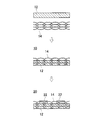
図1(A)は、この発明のフレキシブル粘土膜を示す平面図であり、図1(B)はその断面図である。フレキシブル粘土膜10は、粘土膜12を含む。粘土膜12の内部には、平面方向に1つの骨材14が配置される。骨材14は、厚み方向に複数の骨材を配置してもよい。ひねり強度がさらに向上するからである。ただし、骨材が増えるとフレキシブル性が低下するおそれがあるため、骨材は1つであることが好ましい。また、骨材14は、例えば網目状の開口部を有するシート状である。ただし、骨材14の開口部の形状は、三角形や四角形等であってもよく、任意の形状にすることができる。
このフレキシブル粘土膜10は、たとえば、粘土膜12を形成するためのスラリーの上に骨材14の一方面を接触させ、スラリーを乾燥させたのち、乾燥したスラリーを下にして、上から粘土分散液を骨材14に含浸させて乾燥させることにより、骨材14の網目状の開口部に粘土シート12a,12bが入り込むようにして一体化される。あるいは、骨材をスラリーの中に浸しておき、引き上げながら乾燥を行うことで、骨材14の開口部に粘土シート12a,12bが入り込んだフレキシブル粘土膜10を形成することもできる。なお、骨材14は、図1に示すように、粘土膜12の主面に対して平行に配置されることが好ましいが、多少傾いていてもよい。また、図1(A)(B)では、骨材14の外縁、すなわち外周端部が粘土膜12の外縁と同一となるように形成されているが、骨材14の外縁部側が露出して、粘土膜12の外縁から骨材14の外周側が突出するような構成であってもよい。
粘土シート12a,12bを作製するには、たとえば、粘土を均一に水に分散させることにより、スラリーが形成される。このスラリーをPETフィルムなどの上に展開し、乾燥させることにより、粘土粒子を高度に配向して積層させた粘土シート12a,12bを得ることができる。ここで、粘土粒子が配向して積層されたというのは、扁平状の粘土粒子の平面を粘土膜の主面と平行な方向に敷き詰め、粘土膜の主面に垂直な方向に高い周期性をもたせることをいう。
なお、粘土シート12a,12bを成膜する際に、自立膜としての機械的強度を向上させるために、粘土シート12a,12bに樹脂を添加してもよい。ただし、樹脂の含有量が多いと、乾燥時に、骨材14の開口部の中で粘土シートが収縮し、粘土膜12が剥がれることがあり、緻密な構造を得ることが難しくなる。そのため、粘土シート12a,12bの樹脂の含有量は20重量%以下であることが好ましい。なお、必要に応じて、粘土と樹脂に加えて、無機物を添加してもよい。なお、この粘土シートは、単独で300℃の温度で加熱しても自立膜としての機械的強度やフレキシブル性に変化がないといった耐熱性を備えている。
粘土としては、天然粘土または合成粘土を用いることができ、たとえば、雲母、バーミキュライト、モンモリロナイト、バイデライト、サポナイト、ヘクトライト、スチーブンサイト、マガディアイト、アイラライト、カネマイト、イライト、セリサイト、スメクタイトの中の1種以上が用いられる。粘土粒子は、例えば、層厚約1nm、粒子径1μm、アスペクト比約300程度のものが用いられる。また、骨材14としては、特にひねりに対して大きい強度を得るために、たとえば、ガラスクロス、金網、エキスパンドメタルなどの無機物で形成されたものが用いられる。特に、金属材料で形成された骨材14を用いることにより、ひねりに対する強度を大きくすることができ、さらに、高い熱伝導性を得ることができる。
特に、金属材料で形成された骨材14を用いる際に、エキスパンドメタルなどのような平坦な面を有する骨材14を用いることにより、金属線を編んだ金網のような凹凸のある面を有する骨材14のように織り目部分に応力が集中することがなく、ひねりに対する強度を大きくすることができる。また、エキスパンドメタルなどのような平坦な面を有する骨材14を用いることにより、フレキシブル粘土膜10の平坦性を向上させることができる。
また、金属材料で形成された骨材14を用いる場合には、骨材14が粘土膜の主面から露出せず厚み方向において粘土膜の内部に存在していることが好ましい。金属材料が露出していると、粘土膜の両主面間の絶縁性が確保できないからである。ただし、絶縁性が求められない部分にフレキシブル粘土膜を用いる場合には、金属材料からなる骨材14が粘土膜12の主面から露出していてもよいことは言うまでもない。この場合、同じ場所において骨材14の両面が露出せず、開口部に入り込んだ粘土が骨材14の少なくとも片方の主面において繋がっている必要がある。
このような骨材14の厚みは、70μm以上150μm以下であることが好ましい。骨材14の厚みが70μm以上であると、骨材自身の強度が強く、ひねりに対する強度がより大きくなる。また、骨材14の厚みが150μm以下であると、骨材14に力が加わった際に、骨材14が変形しやすく、フレキシブル性が優れる。
このようにして得られたフレキシブル粘土膜10は、骨材14の網目状の開口部に粘土膜12が入り込み、粘土膜12と1つの骨材14とが一体化された構成となっている。粘土膜12と骨材14とを一体化したものにひねりを加えても、骨材自身がひねる方向への力によって強く変形しないため、粘土膜12に大きな応力が生じることはなく、割れには至らない。しかし、骨材自身は一方方向に折り曲げが可能であるため、必要な可撓性は失われない。そのため、粘土膜として自立する機械的強度を有するとともに、フレキシブル性に優れ、ひねりに対する強度が大きいフレキシブル粘土膜10を得ることができる。
このフレキシブル粘土膜10は、たとえば、電子回路用のフレキシブル基板として用いることができる。この場合、粘土膜12の材料として絶縁体材料が用いられ、骨材14が露出していないフレキシブル基板上に回路パターンが形成される。回路パターンは、たとえば、上述のような方法で形成されたフレキシブル粘土膜10上にCu箔を積層し、感光性樹脂などでレジストを形成して、エッチングおよびレジスト除去を行うことにより形成される。このような構成を採用することにより、フレキシブル基板の製造工程において、搬送時にひねるような力が加わっても、フレキシブル粘土膜の破損を防止することができる。また、このようなフレキシブル基板を用いた電子回路は、たとえば、ひねるような応力が加わる可能性のあるカメラや携帯電話などに使用することができる。
フレキシブル粘土膜10を用いて回路パターンを有するフレキシブル基板20を形成する場合、図2に示すように、粘土膜12と骨材14とを組み合わせる際に、粘土膜12の主面から骨材14が露出している構成とすることができる。このようなフレキシブル基板20を形成する場合、骨材14として、ガラス不織布やグラスウールなどの絶縁性をもつシート状あるいは網状の材料が使用される。そして、回路パターンの電極22は、粘土膜12の骨材14が露出した面に形成される。このとき、粘土膜12の主面に露出した骨材14が電極16の内部に入り込むようにして、粘土膜12上に電極16が形成される。
このようなフレキシブル基板20を作製するために、たとえば、粘土と、粘土の粘土粒子を膨潤させる液体とが、スラリー状となるように混合されて、粘土スラリーが形成される。また、網目状の開口部を有する絶縁材料で形成されたシート状の骨材14が準備される。
このような骨材14に、例えばコーターを用いて粘土スラリーを含浸させることにより、骨材14の開口部が粘土スラリーで埋められる。このとき、骨材14の一方主面が露出するようにして、粘土スラリーが骨材14に含浸させられる。そして、粘土スラリーを乾燥させることにより、粘土粒子を配向して積層させて、粘土膜12の主面に骨材14が露出したフレキシブル粘土膜10を得ることができる。
また、粘土と、粘土の粘土粒子を膨潤させる液体とをゲル状になるように混合した粘土ゲルを用いることもできる。この粘土ゲルがシート状に形成され、絶縁性を有する骨材14の表面に配置される。そして、粘土ゲルを骨材14に向かってプレスすることにより、骨材14の開口部に粘土ゲルが入り込み、骨材14の開口部が粘土ゲルで埋められる。さらに、粘土ゲルを乾燥させることにより、粘土粒子を配向して積層させて、フレキシブル粘土膜10が形成される。ここで、たとえば、粘土ゲルの厚みを骨材14の厚みより薄くしておくことにより、粘土膜12の主面に骨材14が露出したフレキシブル粘土膜10を得ることができる。
このようにして得られたフレキシブル粘土膜10の骨材露出面に、たとえば導電性ペーストをスクリーン印刷し、焼き付けることによって電極22が形成される。ここで、導電性ペーストを印刷すると、粘土膜12から露出した骨材14に導電性ペーストが絡みつき、この導電性ペーストを焼き付けることにより、骨材14が内部に入り込んだ電極22が形成される。
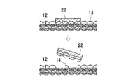
このようにして得られたフレキシブル基板20においては、フレキシブル粘土膜10への電極の密着強度を向上させることができる。骨材14が粘土膜12の主面に露出していない場合、図3に示すように、電極22が積層された粘土粒子の上に配置されている。ここで、粘土粒子間の接着力は弱いため、電極22に力が加わると、粘土粒子が電極22に付着したまま、電極22が粘土膜12から剥離してしまう。
それに対して、骨材14が露出した粘土膜12上に電極22が形成されている場合、図4に示すように、電極22に骨材14が入り込んでいる。そのため、粘土膜12から電極22を剥離するためには、骨材14を引きちぎる必要がある。したがって、粘土膜12に対する電極22の密着強度は、骨材14が露出していない粘土膜12に形成された電極22に比べて強いものとなる。
なお、骨材14が粘土膜12の表面に露出したフレキシブル粘土膜10を用いる場合、骨材14は、ガラス不織布やグラスウールなどの絶縁性をもつシート状または網状の材料である必要がある。なぜならば、電極22が骨材14と絡み合うことで電極22の密着強度を得ているため、導電性を有する骨材14を用いると、ショートして回路基板として利用することができないからである。
なお、骨材14の開口部を粘土スラリーで埋める方法や、骨材14に向かって粘土ゲルをプレスする方法は、金属材料などの導電性の材料を用いた骨材14を使用する場合にも適用することができる。導電性を有する骨材14を用いる場合、骨材14は粘土膜12の主面に露出すると、粘土膜主面に形成された電極22がショートするため、骨材14は粘土膜12の内部に配置されている必要がある。この場合、上述のように、粘土膜12を形成するための粘土スラリーの上に骨材14の一方面を接触させ、粘土スラリーを乾燥させたのち、乾燥した粘土スラリーを下にして、上から粘土分散液を骨材14に含浸させて乾燥させることにより、骨材14が粘土膜12の主面に露出しないようにしてフレキシブル粘土膜10を形成することができる。また、骨材14の両主面に粘土ゲルを配置し、両側から粘土ゲルをプレスして乾燥させることにより、骨材14が粘土膜12の主面に露出しないようにしてフレキシブル粘土膜10を形成することができる。
また、骨材14に粘土ゲルをプレスする方法の場合、高濃度のゲルをプレスすることで、スラリー化のプロセスを簡略化することができる。さらに、使用する水の量を大幅に減らすことができるため、乾燥時間を短くすることができ、フレキシブル粘土膜10の製造コストを低減することができる。
粘土(クニミネ工業株式会社製のクニピア-F)10gを水90gに分散させて、スラリーを形成した。ポリエチレンテレフタレート(PET)フィルム上にスラリーを流し出し、その上に骨材としてのガラス不織布を乗せて、40℃で10時間乾燥させた。そして、スラリー側の面を下にし、ガラス不織布を乗せた側の面を上にして、上から粘土分散液を含浸させ、40℃で10時間乾燥させた。そののち、乾燥したスラリーをPETフィルムから剥がし、350℃~500℃で熱処理を行い、粘土層間の水分を完全に除去してフレキシブル粘土膜を形成した。ここで、骨材であるガラス不織布の厚みを表1に示すように変えて、ひねり耐性と耐熱性とを測定した。ここで、耐熱性としては、得られたフレキシブル粘土膜を500℃まで高温化し、そののちにひねり耐性を測定した。ひねり耐性は、40mm×60mmの大きさのフレキシブル粘土膜の長手方向の両端を固定し、固定部分を回転させることにより、フレキシブル粘土膜にひねりを加えて、90°までひねり可能なものを「◎」、60°までひねり可能だが90°まではひねり不可なものを「○」、60°まではひねり不可なものを「×」とした。これらの結果を表1の試料番号1~5に示した。
また、骨材として金属網を用いて、上述の方法により、フレキシブル粘土膜を形成した。このとき、金属網は粘土膜の主面から露出せず厚み方向において粘土膜の内部に存在させた。そして、金属網の厚みを変えてフレキシブル粘土膜を形成し、ひねり耐性と耐熱性とを測定した。そして、その結果を表1の試料番号6~9に示した。
また、骨材としてエキスパンドメタルを用いて、上述の方法により、フレキシブル粘土膜を形成した。そして、得られたフレキシブル粘土膜について、ひねり耐性と耐熱性とを測定し、その結果を表1の試料番号10に示した。さらに、粘土として株式会社ホージュン製のベンゲルAを使用し、骨材としてエキスパンドメタルを用いて、上述の方法により、フレキシブル粘土膜を形成した。そして、得られたフレキシブル粘土膜について、ひねり耐性と耐熱性とを測定し、その結果を表1の試料番号11に示した。
比較例として、粘土(クニミネ工業株式会社製のクニピア-F)10gを水90gに分散させて、スラリーを形成した。PETフィルム上にスラリーを流し出し、60℃で30分乾燥させた後、乾燥したスラリーをPETフィルムから剥がし、350℃~500℃で熱処理を行い、粘土層間の水分を完全に除去した。そして、得られたフレキシブル粘土膜について、ひねり耐性と耐熱性とを測定し、その結果を表1の試料番号12に示した。
また、別の比較例として、粘土(クニミネ工業株式会社製のクニピア-F)10gを水90gに分散させて、スラリーを形成した。PETフィルム上にスラリーを流し出し、その上に厚み250μmのガラス不織布を乗せて、60℃で30分乾燥させた。なお、粘土分散液は、厚みが250μmあるガラス不織布に付与されることにより、ガラス不織布の表面に塗布された状態となり、ガラス不織布に含浸されてはいない。ガラス不織布に粘土分散液を塗布した後、60℃で30分乾燥させ、乾燥したスラリーをPETフィルムから剥がし、350℃~500℃で熱処理を行い、粘土層間の水分を完全に除去した。それにより、ガラス不織布と粘土膜とが積層構造になったフレキシブル粘土膜が得られた。そして、得られたフレキシブル粘土膜について、ひねり耐性と耐熱性とを測定し、その結果を表1の試料番号13に示した。

表1の試料番号1~5からわかるように、骨材としてのガラス不織布と粘土膜とを一体化させることにより、少なくとも60°までフレキシブル粘土膜をひねることができる。特に、試料番号2~4に示すように、ガラス不織布の厚みが70μm以上で150μm以下であるとき、フレキシブル粘土膜を90°までひねることができる。なお、試料番号1に示すように、ガラス不織布の厚みが70μm未満である場合、フレキシブル粘土膜を90°ひねると、ガラス不織布が割れ、粘土膜も割れた。これは、ガラス不織布の厚みが小さいため、ガラス不織布のひねりに対する強度が弱いためであると考えられる。また、試料番号5に示すように、ガラス不織布の厚みが150μmを超えると、骨材の厚みが厚いために、骨材自体が60°までしかひねることができない。
また、試料番号6~9からわかるように、骨材として金網を用いた場合においても、金網と粘土膜とを一体化することにより、少なくとも60°までフレキシブル粘土膜をひねることができる。なお、試料番号6に示すように、金網の厚みが70μm未満である場合、フレキシブル粘土膜を90°ひねると金網が伸びて、粘土膜が破れた。また、試料番号9に示すように、金網の厚みが150μmを超えると、骨材の厚みが厚いために、骨材自体が60°までしかひねることができない。
さらに、試料番号10、11からわかるように、骨材としてエキスパンドメタルを用いた場合においても、エキスパンドメタルと粘土膜とを一体化することにより、良好なひねり耐性を得ることができた。ここで、試料番号10、11の試験方法において、異なる種類の粘土を用いたが、両方とも良好な結果を得ることができた。
また、試料番号12に示すように、骨材を用いない場合、フレキシブル粘土膜を30°までひねると、粘土膜が割れた。
さらに、試料番号13からわかるように、ガラス不織布に粘土分散液を含浸させず、粘土膜とガラス不織布とを積層状態としたとき、フレキシブル粘土膜を30°までひねると、ガラス不織布が剥離して、粘土膜が割れた。なお、ガラス不織布と粘土膜とが積層構造になったのは、ガラス不織布が厚いことだけでなく、乾燥条件にも影響を受けているものと思われる。
なお、フレキシブル基板の作製の例として、粘土スラリーをPETフィルム上に展開して、粘土シートを得た。得られた粘土シートに金属網を乗せ、その上に軽く湿らせた粘土シートを金属網に乗せた。このとき、粘土シートの湿らせた面が金属網側にくるようにして、粘土シートを重ねた。さらに、その上にCu箔を乗せ、200MPaの圧力、60℃の温度を付加した。得られたCu箔積層体を350℃~500℃の低酸素分圧下で熱処理し、完全に水分を除去した。その後、Cu箔上に感光性樹脂でレジストを形成し、エッチング、レジスト除去の過程を経て、電極パターンを形成した。得られたフレキシブル基板は、350℃の温度でも、寸法変形が見られず、高い機械的強度をもつものであった。
粘土(クニミネ工業株式会社製のクニピア-F)5gを水95gに分散させ、粘土スラリーを得た。PETフィルム上に厚さ100μmのガラス不織布をのせ、その上に粘土スラリーを流し出し、ギャップ1.5mmのコーターですりきった。その後、50℃で10時間乾燥し、PETフィルムから剥離した。得られた膜を350℃~500℃で熱処理を行い、粘土層間の水分を完全に除去して、厚さ100μmの粘土膜を形成した。得られた粘土膜のPETフィルム側の主面には、ガラス不織布が露出していた。この粘土膜のガラス不織布露出面に導電性ペーストをスクリーン印刷し、焼き付けることによって一辺が2mmの正方形の電極を形成した。
粘土膜の電極形成面に幅18mmのセロハン粘着テープ(ニチバン株式会社製のCT-18)の粘着面を親指の腹で押し付けたのち、一気にセロハン粘着テープを剥がした。そして、そのときの粘土膜上での電極の有無や剥離の状態を調べた。その結果を表2の試料番号1に示した。なお、表2において、電極が粘土膜に残っている場合には「○」を付し、電極が粘土膜から剥離した場合には「×」を付した。
粘土(クニミネ工業株式会社製のクニピア-F)5gを水20gと練り合わせ、高粘性の粘土ゲルを作製した。PETフィルム上に粘土ゲルをヘラなどで一辺が100mmの正方形となるように引き延ばした。この粘土ゲル上に厚さ150μmのガラス不織布をのせ、その上に濾紙をのせて、1tの圧力で1分間プレスした。そののち、50℃で10時間乾燥し、濾紙およびPETフィルムを剥がした。得られた膜を350℃~500℃で熱処理を行い、粘土層間の水分を完全に除去して粘土膜を得た。得られた粘土膜の濾紙側の主面には、ガラス不織布が露出していた。この粘土膜のガラス不織布露出面に導電性ペーストをスクリーン印刷し、焼き付けることによって一辺が2mmの正方形の電極を形成した。
このようにして得られた粘土膜上の電極についても、上述のようにして、セロハン粘着テープを用いた剥離試験を行った。そして、その結果を表2の試料番号2として示した。
比較例として、骨材を用いない粘土膜について、電極の剥離試験を行った。粘土(クニミネ工業株式会社製のクニピア-F)5gを水95gに分散させて粘土スラリーを作製した。PETフィルム上に粘土スラリーを流し出し、ギャップ1mmのコーターですり切ったのち、50℃で乾燥させて膜を作製した。この膜をPETフィルムから剥がし、350℃~500℃で熱処理を行い、結晶層間の水分を完全に除去して、厚さ60μmの粘土膜を作製した。次に、粘土膜の主面に導電性ペーストをスクリーン印刷し、焼き付けることによって一辺が2mmの正方形の電極を形成した。
このようにして得られた粘土膜上の電極についても、上述のようにして、セロハン粘着テープを用いた剥離試験を行った。そして、その結果を表2の試料番号3として示した。
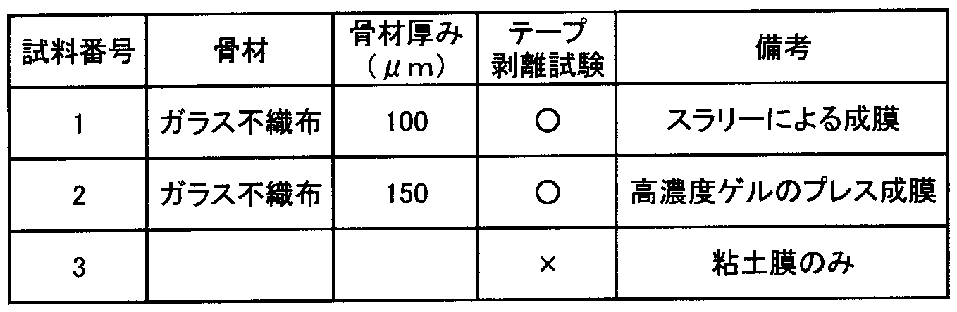
表2の試料番号1、2からわかるように、骨材としてガラス不織布を用いた粘土膜では、剥離試験において、電極は粘土膜上に残っており、粘土膜に変化は見られなかった。それに対して、試料番号3からわかるように、骨材を用いない粘土膜では、電極が剥離した。そして、電極の剥離面を観察すると、粘土膜が付着していた。試料番号1、2のフレキシブル基板では、粘土膜のガラス不織布露出面に電極を形成するときに、導電性ペーストがガラス不織布に入り込み、電極とガラス不織布とが絡み合っているために、電極と粘土膜との間に強い密着強度が生じたものと考えられる。さらに、試料番号1、2の粘土膜では、骨材が存在することにより、試料番号3の粘土膜に比べて、大きい機械的強度を有している。
10 フレキシブル粘土膜
12 粘土膜
12a,12b 粘土シート
14 骨材
20 フレキシブル基板
22 電極
12 粘土膜
12a,12b 粘土シート
14 骨材
20 フレキシブル基板
22 電極
Claims (11)
- 粘土粒子が配向して積層された粘土膜と、
網目状の開口部を有するシート状の骨材とを含み、
前記骨材の外縁は前記粘土膜の外縁と同一またはそれよりも外側にあり、
前記骨材の開口部が前記粘土膜によって埋められている、フレキシブル粘土膜。 - 前記骨材の厚みが70μm以上で150μm以下である、請求項1に記載のフレキシブル粘土膜。
- 前記骨材が無機物からなる、請求項1または請求項2に記載のフレキシブル粘土膜。
- 前記無機物が金属である、請求項3に記載のフレキシブル粘土膜。
- 前記骨材は、1枚の板材に前記開口部を形成したものである、請求項3または請求項4に記載のフレキシブル粘土膜。
- 前記骨材は、粘土膜の主面から露出せず厚み方向において前記粘土膜の内部に存在していることを特徴とする、請求項4または請求項5に記載のフレキシブル粘土膜。
- 前記骨材は絶縁性材料からなり、前記骨材は前記粘土膜の主面から露出している、請求項3に記載のフレキシブル粘土膜。
- 請求項1ないし請求項7のいずれかに記載のフレキシブル粘土膜を絶縁層として用いた、フレキシブル基板。
- 請求項7に記載のフレキシブル粘土膜を用いたフレキシブル基板であって、
前記フレキシブル粘土膜の表面に電極が形成されており、
前記フレキシブル粘土膜に埋められている前記骨材の露出部が前記電極の内部に入り込んでいる、フレキシブル基板。 - 粘土粒子と、前記粘土粒子を膨潤させる液体とをスラリー状になるように混合した粘土スラリーを準備する工程、
網目状の開口部を有するシート状の骨材を準備する工程、
前記骨材に前記粘土スラリーを含浸させることにより、前記骨材の開口部を前記粘土スラリーによって埋める工程、および
前記粘土スラリーを乾燥させることにより、前記液体を揮発させるとともに、前記粘土粒子を配向して積層させる工程を含む、フレキシブル粘土膜の製造方法。 - 粘土粒子と、前記粘土粒子を膨潤させる液体とをゲル状になるように混合した粘土ゲルを準備する工程、
網目状の開口部を有するシート状の骨材を準備する工程、
前記骨材の表面に前記粘土ゲルを配置する工程、
前記ゲルをプレスすることにより、前記骨材の開口部を前記粘土ゲルによって埋める工程、および
前記粘土ゲルを乾燥させることにより、前記液体を揮発させるとともに、前記粘土ゲルを配向して積層させる工程を含む、フレキシブル粘土膜の製造方法。
Applications Claiming Priority (2)
| Application Number | Priority Date | Filing Date | Title |
|---|---|---|---|
| JP2011082678 | 2011-04-04 | ||
| JP2011-082678 | 2011-04-04 |
Publications (1)
| Publication Number | Publication Date |
|---|---|
| WO2012137559A1 true WO2012137559A1 (ja) | 2012-10-11 |
Family
ID=46968963
Family Applications (1)
| Application Number | Title | Priority Date | Filing Date |
|---|---|---|---|
| PCT/JP2012/054886 Ceased WO2012137559A1 (ja) | 2011-04-04 | 2012-02-28 | フレキシブル粘土膜とその製造方法およびそれを用いたフレキシブル基板 |
Country Status (1)
| Country | Link |
|---|---|
| WO (1) | WO2012137559A1 (ja) |
Citations (2)
| Publication number | Priority date | Publication date | Assignee | Title |
|---|---|---|---|---|
| JP2006159865A (ja) * | 2004-12-10 | 2006-06-22 | National Institute Of Advanced Industrial & Technology | 布と粘土からなる複合膜 |
| JP2007042693A (ja) * | 2005-07-29 | 2007-02-15 | National Institute Of Advanced Industrial & Technology | フレキシブル基板 |
-
2012
- 2012-02-28 WO PCT/JP2012/054886 patent/WO2012137559A1/ja not_active Ceased
Patent Citations (2)
| Publication number | Priority date | Publication date | Assignee | Title |
|---|---|---|---|---|
| JP2006159865A (ja) * | 2004-12-10 | 2006-06-22 | National Institute Of Advanced Industrial & Technology | 布と粘土からなる複合膜 |
| JP2007042693A (ja) * | 2005-07-29 | 2007-02-15 | National Institute Of Advanced Industrial & Technology | フレキシブル基板 |
Similar Documents
| Publication | Publication Date | Title |
|---|---|---|
| JP3947226B2 (ja) | ロールコーティングされたelパネル | |
| US8743528B2 (en) | Capacitor | |
| CN105161803B (zh) | 一种石墨烯薄膜频率选择表面 | |
| CN102308366A (zh) | 触摸屏及其制备方法 | |
| KR101586812B1 (ko) | 연성인쇄회로기판의 제조방법 및 이에 의해 제조된 연성인쇄회로기판 | |
| JPWO2001003478A1 (ja) | プリント配線板及びプリント配線板用プリプレグ | |
| WO2006126333A1 (ja) | 積層セラミック電子部品およびその製造方法 | |
| CN103827789A (zh) | 触控面板及包括所述触控面板的显示器件 | |
| JP2016115762A (ja) | 配線印刷物及びその製造方法 | |
| CN110972458A (zh) | 一种无线充电屏蔽片的制备方法及屏蔽片 | |
| TWI702621B (zh) | 多層積層板及使用其之多層印刷電路板之製造方法 | |
| CN106332534A (zh) | 吸波体结构 | |
| WO2012137559A1 (ja) | フレキシブル粘土膜とその製造方法およびそれを用いたフレキシブル基板 | |
| JPWO2010035461A1 (ja) | 積層セラミック電子部品の製造方法 | |
| JP4836166B2 (ja) | 粘着粘土膜及びその使用方法 | |
| CN108184310B (zh) | 透明柔性多层pcb的制作方法 | |
| JP2011204849A (ja) | 積層セラミック電子部品の製造方法 | |
| CN102365694A (zh) | 层叠陶瓷电子部件的制造方法 | |
| CN204230306U (zh) | 一种柔性电极结构、柔性显示基板及显示装置 | |
| JP4916057B2 (ja) | Fpc用保護フィルム、fpc用保護フィルム付樹脂導体箔積層体およびそれを用いたフレキシブルプリント配線基板の製造方法 | |
| CN105900179A (zh) | 导电性胶带 | |
| JP2010040628A (ja) | 積層型セラミック電子部品の製造方法 | |
| CN1171257C (zh) | 陶瓷电容器的制造方法和陶瓷电容器 | |
| CN116666567A (zh) | 极片、锂离子电池及其制备方法 | |
| JP4779151B2 (ja) | フレキシブル基板 |
Legal Events
| Date | Code | Title | Description |
|---|---|---|---|
| 121 | Ep: the epo has been informed by wipo that ep was designated in this application |
Ref document number: 12767453 Country of ref document: EP Kind code of ref document: A1 |
|
| NENP | Non-entry into the national phase |
Ref country code: DE |
|
| 122 | Ep: pct application non-entry in european phase |
Ref document number: 12767453 Country of ref document: EP Kind code of ref document: A1 |
|
| NENP | Non-entry into the national phase |
Ref country code: JP |