WO2012137414A1 - 位置算出方法及び位置算出装置 - Google Patents
位置算出方法及び位置算出装置 Download PDFInfo
- Publication number
- WO2012137414A1 WO2012137414A1 PCT/JP2012/001692 JP2012001692W WO2012137414A1 WO 2012137414 A1 WO2012137414 A1 WO 2012137414A1 JP 2012001692 W JP2012001692 W JP 2012001692W WO 2012137414 A1 WO2012137414 A1 WO 2012137414A1
- Authority
- WO
- WIPO (PCT)
- Prior art keywords
- degree
- measurement result
- influence
- gps
- calculation
- Prior art date
- Legal status (The legal status is an assumption and is not a legal conclusion. Google has not performed a legal analysis and makes no representation as to the accuracy of the status listed.)
- Ceased
Links
Images





Classifications
-
- G—PHYSICS
- G01—MEASURING; TESTING
- G01S—RADIO DIRECTION-FINDING; RADIO NAVIGATION; DETERMINING DISTANCE OR VELOCITY BY USE OF RADIO WAVES; LOCATING OR PRESENCE-DETECTING BY USE OF THE REFLECTION OR RERADIATION OF RADIO WAVES; ANALOGOUS ARRANGEMENTS USING OTHER WAVES
- G01S19/00—Satellite radio beacon positioning systems; Determining position, velocity or attitude using signals transmitted by such systems
- G01S19/38—Determining a navigation solution using signals transmitted by a satellite radio beacon positioning system
- G01S19/39—Determining a navigation solution using signals transmitted by a satellite radio beacon positioning system the satellite radio beacon positioning system transmitting time-stamped messages, e.g. GPS [Global Positioning System], GLONASS [Global Orbiting Navigation Satellite System] or GALILEO
- G01S19/42—Determining position
- G01S19/45—Determining position by combining measurements of signals from the satellite radio beacon positioning system with a supplementary measurement
- G01S19/47—Determining position by combining measurements of signals from the satellite radio beacon positioning system with a supplementary measurement the supplementary measurement being an inertial measurement, e.g. tightly coupled inertial
-
- G—PHYSICS
- G01—MEASURING; TESTING
- G01C—MEASURING DISTANCES, LEVELS OR BEARINGS; SURVEYING; NAVIGATION; GYROSCOPIC INSTRUMENTS; PHOTOGRAMMETRY OR VIDEOGRAMMETRY
- G01C21/00—Navigation; Navigational instruments not provided for in groups G01C1/00 - G01C19/00
- G01C21/10—Navigation; Navigational instruments not provided for in groups G01C1/00 - G01C19/00 by using measurements of speed or acceleration
- G01C21/12—Navigation; Navigational instruments not provided for in groups G01C1/00 - G01C19/00 by using measurements of speed or acceleration executed aboard the object being navigated; Dead reckoning
- G01C21/16—Navigation; Navigational instruments not provided for in groups G01C1/00 - G01C19/00 by using measurements of speed or acceleration executed aboard the object being navigated; Dead reckoning by integrating acceleration or speed, i.e. inertial navigation
- G01C21/165—Navigation; Navigational instruments not provided for in groups G01C1/00 - G01C19/00 by using measurements of speed or acceleration executed aboard the object being navigated; Dead reckoning by integrating acceleration or speed, i.e. inertial navigation combined with non-inertial navigation instruments
Definitions
- the present invention relates to a position calculation method using measurement results of a satellite positioning unit and an inertial positioning unit provided in a moving body.
- inertial sensors In various fields such as so-called seamless positioning, motion sensing, and attitude control, the use of inertial sensors is attracting attention.
- an acceleration sensor As an inertial sensor, an acceleration sensor, a gyro sensor, a pressure sensor, a geomagnetic sensor, and the like are widely known.
- An inertial navigation system (hereinafter referred to as “INS (Inertial Navigation System)”) that performs inertial navigation calculation using the detection result of the inertial sensor has also been devised.
- INS Inertial Navigation System
- Patent Document 1 discloses a technique for correcting an INS calculation result using GPS (Global Positioning System).
- the technology for correcting the INS calculation result using GPS is based on the assumption that the GPS calculation result is correct.
- the technique disclosed in Patent Document 1 is also the same.
- the accuracy of the GPS calculation result may decrease due to various factors such as the signal strength of the GPS satellite signal received from the GPS satellite, the reception environment, the sky arrangement of the GPS satellite, and the multipath. For this reason, always correcting the INS calculation result using the GPS calculation result does not necessarily lead to an improvement in the accuracy of position calculation.
- the present invention has been made in view of the above-described problems, and is intended to more accurately calculate the position of a moving body by using the measurement results of a satellite positioning unit and an inertial positioning unit provided in the moving body.
- the purpose is to propose the method.
- a first mode for solving the above problems is a first measurement result of a satellite positioning unit provided in a moving body, and a second measurement result of an inertial positioning unit provided in the moving body.
- the mobile body A position calculation device for calculating the position of the first measurement result, the first degree of influence of the first measurement result on the second measurement result until the given condition is satisfied after the position calculation is started.
- an influence degree setting unit for setting the influence degree to a second degree lower than the first degree, and the first measurement based on the influence degree.
- You may comprise the position calculation apparatus provided with the coupling process part which performs the coupling process of a result and a said 2nd measurement result, and calculates the position of the said mobile body.
- the degree of influence of the first measurement result on the second measurement result is set to the first degree until the given condition is satisfied after the position calculation is started.
- the influence degree is set to a second degree lower than the first degree. That is, the degree of influence of the measurement result of the satellite positioning unit on the measurement result of the inertial positioning unit is changed before and after the given condition is satisfied.
- the influence degree includes an execution frequency of adopting the first measurement result and executing the coupling process
- Setting to the first degree includes setting the execution frequency to the first frequency
- setting to the second degree means that the execution frequency is lower than the first frequency.
- calculating the position includes configuring the position calculation method including performing the coupling process adopting the first measurement result according to the execution frequency. Good.
- the first measurement result is used to set the execution frequency for executing the coupling process to the first frequency.
- the execution frequency is set to a second frequency lower than the first frequency. That is, after a given condition is satisfied, the frequency of adopting the first measurement result in the coupling process is lowered, and the degree of influence of the first measurement result on the second measurement result is lowered.
- adopts the measurement result of a satellite positioning unit for a coupling process can be optimized, and the effectiveness of a coupling process can be improved.
- the coupling process includes a Kalman filter process using the first measurement result as an observation amount, and the influence degree includes the Kalman filter.
- An error parameter value used for processing is included, and setting to the first degree includes setting the error parameter value to the first parameter value, and setting to the second degree Setting the error parameter value to a second parameter value larger than the first parameter value, and calculating the position using the first measurement result and the error parameter value It is good also as comprising a position calculation method including performing a Kalman filter process.
- the error parameter value used for the Kalman filter process is set to the first parameter value until a given condition is satisfied. After a given condition is met, the error parameter value is set to a second parameter value that is greater than the first parameter value.
- the error parameter value is, for example, a value that determines the degree of emphasis on the first measurement result in the Kalman filter process. Setting a large error parameter value corresponds to lowering the degree of influence of the first measurement result on the second measurement result. By optimizing the error parameter value, the accuracy of the calculated position of the moving body is improved.
- the calculation of the position is a predetermined position using the first measurement result when the influence level is the first level.
- a position calculation method may be configured in which a position is calculated by executing a calculation process, and the position is calculated by executing the coupling process when the influence degree is the second degree.
- the position is calculated by executing the predetermined position calculation process using the first measurement result.
- the influence degree is the second degree
- the coupling process is executed to calculate the position.
- setting the degree of influence is that the elapsed time from the start of position calculation or the number of position calculations is
- the position calculation method may be configured to include determining that the given condition is satisfied when the accuracy stability condition defined as a time condition for stabilizing the accuracy of the position calculation result is satisfied. Good.
- the accuracy stability condition defined as a temporal condition for stabilizing the accuracy of the position calculation result.
- the degree of influence of the first measurement result on the second measurement result is decreased from the first degree to the second degree.
- calculating the position includes calculating the position obtained from the first measurement result at the start of position calculation. Including setting a reference position for subsequent position calculation, and setting the degree of influence means that the given condition is satisfied when the first measurement result at the start of position calculation satisfies a predetermined good accuracy condition. It is good also as comprising a position calculation method including determining with having been materialized.
- the subsequent position calculation is performed using the position obtained from the first measurement result as the reference position. That is, if the accuracy of the first measurement result is good, the subsequent position calculation can be performed using the position close to the true position as the reference position. Therefore, when the first measurement result at the start of position calculation satisfies a predetermined good accuracy condition, the influence degree is lowered from the first degree to the second degree. As a result, when it can be determined that a highly reliable reference position has been obtained, the position calculation can be performed while reducing the dependency on the measurement result of the satellite positioning unit.
- setting the influence degree is performed when the result of the coupling process satisfies a predetermined good accuracy condition.
- a position calculation method including determining that the given condition is satisfied may be configured.
- the influence degree is lowered from the first degree to the second degree.
- the main lineblock diagram of a position calculation device The block diagram of a 1st position calculation apparatus. Explanatory drawing of the input / output data of a coupling process. Explanatory drawing of a 1st mode setting condition. Explanatory drawing of 2nd mode setting conditions.
- the flowchart which shows the flow of an influence mode setting process. The figure which shows an example of the experimental result which performed position calculation. The figure which shows an example of the experimental result which performed position calculation. The figure which shows an example of the experimental result which performed position calculation. The figure which shows an example of the experimental result which performed position calculation. The figure which shows an example of the experimental result which performed position calculation.
- the system block diagram of a navigation system The block diagram which shows the function structure of a car navigation apparatus.
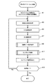
- the flowchart which shows the flow of a 1st navigation process.
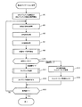
- the flowchart which shows the flow of a coupling process.
- GPS Global Positioning System
- INS Intelligent Navigation System
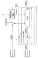
- FIG. 1 is a main configuration diagram of a position calculation apparatus 1 according to the present embodiment.
- the position calculation device 1 is a device (position calculation system) that is provided in a moving body and calculates the position of the moving body.
- the moving body may be a person such as a car, a motorcycle, a bicycle, a ship, a train, or a person.
- a person may carry the position calculation device 1 and the person himself / herself may include the position calculation device 1.
- a unit (module) is illustrated by a double line, and a processing block for performing an arithmetic process using the measurement result of the unit is illustrated by a single line, thereby distinguishing the two.
- FIG. 1 is a main configuration diagram of a position calculation apparatus 1 according to the present embodiment.
- the position calculation device 1 is a device (position calculation system) that is provided in a moving body and calculates the position of the moving body.
- the moving body may be a person such as a car, a motorcycle, a bicycle,
- the position calculation device 1 includes a GPS unit 3 and an INS unit 5 as units (modules). In addition, the position calculation device 1 includes an influence degree setting unit 7 and a coupling processing unit 9 as main processing blocks.
- the GPS unit 3 is a unit (satellite positioning unit) for performing positioning using a satellite positioning system.
- the GPS unit 3 includes an antenna that receives a GPS satellite signal transmitted from a GPS satellite, a processor that processes the received GPS satellite signal, and the like.
- the GPS unit 3 is configured to be able to measure GPS measurement information such as a code phase, a Doppler frequency, a pseudorange, and a pseudorange change rate of a GPS satellite signal.
- the GPS unit 3 is configured to be able to measure the position and speed (speed vector) of the moving body by performing GPS calculation using the GPS measurement information.
- the GPS measurement information and the GPS calculation result are output to the coupling processing unit 9 as a GPS measurement result (first measurement result).
- the INS unit 5 is a unit for performing positioning using inertial navigation (an inertial positioning unit).
- the INS unit 5 includes an inertial sensor such as an acceleration sensor and a gyro sensor, an inertial measurement unit (IMU (Inertial Measurement Unit)) in which the inertial sensor is packaged, a processor for processing the measurement result of the inertial sensor, and the like.
- IMU Inertial Measurement Unit
- the INS unit 5 is configured to be able to measure the acceleration (acceleration vector), angular velocity, etc. of the moving body as INS measurement information using the measurement result of the inertial sensor.
- the INS unit 5 is configured to perform an inertial navigation calculation (INS calculation) using INS measurement information to measure the position, speed (velocity vector), posture angle, and the like of the moving body.
- the INS measurement information and the INS calculation result are output to the coupling processing unit 9 as the INS measurement result (second measurement result).
- the influence degree setting unit 7 sets the influence degree of the GPS measurement result (first measurement result) with respect to the INS measurement result (second measurement result).
- the influence degree setting unit 7 determines whether or not a given condition is satisfied after starting the position calculation. Until the given condition is satisfied, the influence degree of the GPS measurement result on the INS measurement result is set to the first degree, and after the condition is established, the influence degree is lower than the first degree. Set to the second degree.
- the coupling processing unit 9 executes a coupling process between the GPS measurement result (first measurement result) and the INS measurement result (second measurement result) based on the influence degree set by the influence degree setting unit 7. Then, the position of the moving body is calculated.
- FIG. 2 is a configuration diagram of a first position calculation device 1A to which the position calculation device 1 of FIG. 1 is applied.
- the influence degree setting unit 7 in FIG. 1 has an influence mode setting unit 7A
- the coupling processing unit 9 has a Kalman filter processing unit 9A.
- the influence mode setting unit 7A sets the GPS influence mode according to a mode setting condition described later.
- the GPS influence mode is a mode that determines the influence degree of GPS.
- a “high influence mode” that is a mode in which the influence degree of the GPS measurement result on the INS measurement result is relatively high
- a “low influence mode” that is a mode in which the influence degree of the GPS measurement result on the INS measurement result is relatively low. It is assumed that the two types of modes are set alternatively. In the initial setting, the high influence mode is set.
- the Kalman filter processing unit 9A executes a Kalman filter process using the GPS measurement result as an observation amount “Z” to couple (link) the GPS measurement result and the INS measurement result. Specifically, based on the theory of the Kalman filter, a prediction calculation (time update) and a correction calculation (observation update) are performed to estimate the state “X” of the moving object.
- the state “X” of the moving body includes at least the position of the moving body.
- the INS measurement result input from the INS unit 5 is used as the control input “U”, and the state at the current time (current time) from the state correction value “X +” at the previous time (previous time).
- the state prediction value “X ⁇ ” is calculated by performing an operation for predicting “X”.
- the correction calculation for example, using the GPS measurement result input from the GPS unit 3 as the observation amount “Z”, a calculation for correcting the state prediction value “X ⁇ ” calculated by the prediction calculation is performed, and the state correction value “X +” is calculated. "Is calculated. Then, the calculated state correction value “X +” is output as a coupling result.
- the Kalman filter processing unit 9A is configured to be able to apply a constraint condition based on a moving model of a moving object as an observation amount “Z” separately from the GPS measurement result.
- a constraint condition during stop that is a speed constraint condition when the mobile body is stopped
- a “speed constraint condition during travel” that is a speed constraint condition when the mobile body is moving. Assume that the condition applies.
- FIG. 3 is an explanatory diagram of input / output data of the Kalman filter processing.
- the table showing the correspondence between the control input “U”, the observation amount “Z”, and the state “X” is shown.
- coupling There are various types of coupling. Among them, a method called loose coupling (loose coupling) and a method called tight coupling (tight coupling) are generally used.
- the loose coupling method is a coupling method in which the connection between GPS and INS is relatively weak.
- the coupling process is executed with the control input “U” as the INS calculation result (position, velocity, attitude angle, etc.) and the observation amount “Z” as the GPS calculation result (position, velocity, etc.). Then, the moving body information (position, speed, posture angle, etc.) is estimated as the state “X”.
- the tight coupling method is a coupling method in which the connection between GPS and INS is relatively strong.
- the control input “U” is an INS calculation result (position, velocity, attitude angle, etc.)
- the observation amount “Z” is GPS measurement information (code phase, Doppler frequency, pseudorange, pseudorange change rate, etc.) )
- the moving body information position, speed, posture angle, etc. is estimated as the state “X”.
- control input “U” is INS measurement information (acceleration, angular velocity, etc.)
- observation amount “Z” is GPS measurement information (code phase, Doppler frequency, pseudorange, pseudorange change rate, etc.)
- state “X” is used as moving body information (position, speed, posture angle, etc.).
- the position calculation method of the present embodiment can be applied substantially the same to any of the above coupling methods. That is, as the GPS measurement result (first measurement result), GPS measurement information may be applied, or a GPS calculation result may be applied. Further, as the INS measurement result (second measurement result), INS measurement information may be applied, or an INS calculation result may be applied.
- the information used as the INS measurement result and the GPS measurement result can be appropriately set according to the system to be applied.
- arithmetic expressions and parameter values used in the prediction calculation and correction calculation of the Kalman filter process may be set as appropriate according to the system to be applied. Note that specific arithmetic expressions and parameter values can be defined based on a known method, and thus the description thereof is omitted here.
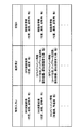
- FIG. 4 is an explanatory diagram of a first mode setting condition used for setting the GPS influence mode, and illustrates a first mode setting condition table that defines the first mode setting condition. .
- the first mode setting condition and the setting mode are defined in association with each other.
- the first mode setting condition is a condition determined based on (1) GPS initial calculation accuracy and (2) elapsed time or number of position calculations since the start of position calculation.
- the GPS initial calculation accuracy is the accuracy of the initial calculation result of the GPS unit 3.
- the first condition corresponds to the GPS measurement result (first measurement result) at the start of position calculation satisfying a predetermined good accuracy condition. Then, when the good accuracy condition is satisfied, the influence degree of the GPS measurement result with respect to the INS measurement result is changed from the first degree (high influence mode) which is the initial setting to the second degree lower than the first degree ( It corresponds to lowering to the low impact mode.
- a “high influence mode” is defined as a setting mode when the condition of elapsed time ⁇ accuracy stabilization time “ ⁇ T ” or position calculation count ⁇ accuracy stabilization count “ ⁇ C ” is satisfied.
- the elapsed time from the start of position calculation exceeds the predetermined accuracy stabilization time “ ⁇ T ”, or if the number of position calculations exceeds the predetermined accuracy stabilization time “ ⁇ C ”, the elapsed time from the start of position calculation corresponds to satisfying the accuracy stability condition defined as a time condition for stabilizing the accuracy of the position calculation result. Then, when this good accuracy condition is satisfied, the degree of influence of the GPS measurement result on the INS measurement result is changed from the initially set first degree (high influence mode) to a second degree lower than the first degree ( It corresponds to lowering to the low impact mode.
- the accuracy stabilization time “ ⁇ T ” and the accuracy stabilization count “ ⁇ C ” can be set as appropriate according to the system to which the position calculation method of this embodiment is applied. For example, if the position calculation is applied to a system that performs “one-second intervals”, “ ⁇ T ” is the number of seconds in the range of “30 to 60 seconds”, and “ ⁇ C ” is “30 to 60 times”. It is effective to set the number of times in the range.
- the position of the moving body is calculated by, for example, performing positioning calculation using the least square method using the pseudoranges observed for each GPS satellite. Further, the relative speed (relative speed vector) between the GPS satellite and the moving body is calculated based on the received frequency error (frequency deviation from the carrier wave frequency) of the received GPS satellite signal, and using this, the speed of the moving body (relative speed vector) is calculated. Velocity vector). At this time, by performing a known error estimation calculation, it is possible to estimate the maximum error that can be included in the calculated position and velocity (velocity vector).
- a threshold for the error estimated by the above error estimation calculation is determined in advance. For example, “10 [m]” is set as the threshold value for the position error, and “1 [m / s]” is set as the threshold value for the speed error. Then, the threshold value determination for the position error and the speed error is performed to determine the GPS initial calculation accuracy.
- the GPS initial calculation accuracy may be determined by applying an AND condition to each threshold determination result, or the OR condition may be applied to determine the GPS initial calculation accuracy.
- the GPS influence mode is set to “low influence mode”, or the GPS influence mode is set to “high influence mode” even though the initial GPS calculation precision is not good. Seemingly contradictory at first glance. However, there is a reason why such a setting method was purposely adopted.
- a reference position and a reference direction are required. Therefore, for example, one method is considered to perform GPS calculation processing at the start of position calculation, and use the obtained position and orientation as the reference position and reference orientation for subsequent position calculation.
- the subsequent position calculation can be performed based on the highly accurate position and direction. Therefore, even if the GPS influence level is lowered and position calculation is performed depending on INS, stable calculation results with relatively high accuracy can be obtained for a while.
- the initial GPS calculation accuracy is not good, it is necessary to perform subsequent position calculation based on the position and direction with low accuracy. That is, the position calculation is started with the error superimposed from the beginning. In this case, if the GPS influence level is lowered and it depends on INS, the initial error will not be corrected any time.
- the GPS influence mode is set to “low influence mode”, and when the initial GPS calculation precision is not good, the GPS influence mode is set to “high influence mode”. Set. If the position calculation is performed in a state where the GPS influence mode is set to the “high influence mode”, the initial error is gradually corrected as the GPS calculation accuracy is improved. Therefore, when a certain amount of time has elapsed, the GPS influence mode is switched from the “high influence mode” to the “low influence mode” to reduce the dependence on the GPS.
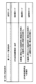
- FIG. 5 is an explanatory diagram of a second mode setting condition used for setting the GPS influence mode, and illustrates a second mode setting condition table that defines the second mode setting condition.
- the second mode setting condition and the setting mode are defined in association with each other.
- the coupling result accuracy means the accuracy of the position of the moving body obtained by performing the coupling process.
- calculation is performed by setting the error “P” of the state “X” to be estimated.
- the accuracy of the state “X” is determined by predicting and correcting the error “P” together with the state “X”. Therefore, the error “P” used in the Kalman filter processing can be used as the coupling result accuracy.
- the error “P” can be represented by an error covariance matrix “P” in a matrix format.
- the accuracy of each element can be estimated from the diagonal component of the error covariance matrix “P”. For example, if the elements of the state “X” are the position, velocity, and attitude angle of the moving body, the diagonal components of the error covariance matrix “P” are the coupling position error, the coupling velocity error, and the coupling attitude angle, respectively. It becomes an error.
- threshold values for coupling position error, coupling speed error, and coupling attitude angle error are determined in advance. For example, “10 [m]” is set as the threshold for the coupling position error, “1 [m / s]” is set as the threshold for the coupling speed error, and “1 [°]” is set as the threshold for the coupling attitude angle error. . Then, a threshold determination is performed for each to determine the coupling result accuracy. In this case, the AND condition may be applied to each threshold determination result to determine the coupling result accuracy, or the OR result may be applied to determine the coupling result accuracy.
- FIG. 6 is a flowchart showing the flow of the influence mode setting process in the present embodiment.
- the influence mode setting unit 7A refers to the first mode setting condition table in FIG. 4 and determines whether or not the first mode setting condition is satisfied (step S1). If the determination result (first determination result) is the high influence mode (step S3; high influence mode), the influence mode setting unit 7A refers to the second mode setting condition table in FIG. The success or failure of the mode setting condition is determined (step S5).
- step S5 If the determination result (second determination result) in step S5 is the high influence mode (step S7; high influence mode), the influence mode setting unit 7A sets the GPS influence mode to the high influence mode (step S9).
- step S9 when the first determination result in step S1 is the low influence mode (step S3; low influence mode), or when the second determination result in step S5 is the low influence mode (step S7; low influence mode). Mode, the influence mode setting unit 7A sets the GPS influence mode to the low influence mode (step S11). Then, the influence mode setting process ends.
- the GPS influence mode is set to the high influence mode only when the first determination result and the second determination result are both in the high influence mode. This has the aim of calculating the position by reducing the GPS influence level as early as possible.
- the coupling processing unit 9 performs the coupling process by changing the calculation setting according to the GPS influence mode.
- the calculation settings include the GPS measurement result adoption frequency and the error parameter value used in the Kalman filter processing.
- the GPS measurement result adoption frequency is an execution frequency at which the GPS measurement result is adopted to execute the coupling process.
- the frequency with which the Kalman filter processing unit 9 ⁇ / b> A adopts the GPS measurement result with the observation amount “Z” and executes the correction calculation corresponds to the GPS measurement result adoption frequency.
- the GPS measurement result adoption frequency is set to a relatively high first frequency.
- the GPS measurement result adoption frequency is set to a second frequency lower than the first frequency.
- the second frequency may be any frequency lower than the first frequency, and a specific value thereof can be set as appropriate.
- the error parameter value is a type of parameter value set in the Kalman filter operation.
- an observation error (observation noise) “R” corresponding to an error of the observation amount “Z” will be described as an example of an error parameter.
- the filter acts so as to estimate the state “X” by trusting and emphasizing the observation amount “Z”.
- the filter acts so as to estimate the state “X” by trusting and emphasizing the observation amount “Z”.
- the filter acts so as to estimate the state “X” by trusting and emphasizing the state predicted value “X ⁇ ” predicted by the prediction calculation.
- the observation error “R” is set to a relatively small first parameter value in order to cause the GPS measurement result to act strongly on the INS measurement result.
- the mode setting of the GPS influence mode is “low influence mode”
- the observation error “R” is larger than the first parameter value.
- the second parameter value only needs to be larger than the first parameter value, and the specific value can be set as appropriate.
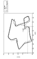
- FIG. 7 is an example of an experimental result to which a conventional position calculation method is applied.
- FIG. 8 is an example of an experimental result to which the position calculation method of the present embodiment is applied.
- the position calculation was performed by giving the first position calculation apparatus 1 ⁇ / b> A as the initial direction an incorrect direction that is shifted by “10 °” from the true direction.
- the horizontal axis indicates the east-west direction
- the vertical axis indicates the north-south direction (unit: meters).
- the starting point was the position of “0 m” in the east-west direction and “0 m” in the north-south direction, and the route from the starting point to the west was followed in a clockwise direction.
- the goal point is a predetermined position near the start point.
- the true trajectory of the moving object is indicated by “dotted line”
- the trajectory calculated by GPS is indicated by “one-dot chain line”
- the trajectory calculated by the coupling process is indicated by “solid line”.
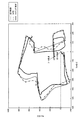
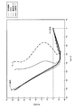
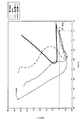
- 9 and 10 are experimental results showing the effectiveness of the first mode setting condition.
- the GPS influence mode is set to “low influence mode” even though the initial GPS calculation accuracy is good, and the initial GPS calculation accuracy is not good.
- the GPS influence mode is set to the “high influence mode”. This is an example of experimental results showing the validity of this paradox that seems to be contradictory at first glance.
- the position calculation was performed by changing the GPS influence mode for each of the cases where the GPS initial calculation accuracy was good and the case where it was not good. That is, it was verified what difference appears in the position calculation result between the case where the GPS influence mode is set to the “low influence mode” and the case where the GPS influence mode is set to the “high influence mode”.
- the horizontal axis indicates the east-west direction
- the vertical axis indicates the north-south direction (unit: meters). Starting from the east-west direction “0m” and the north-south direction “0m”, we headed westward from the start point and followed the route going northward. The goal point is a position in the west direction “70 m” and the north direction “140 m”.
- the true trajectory of the moving object is “dotted line”
- the trajectory calculated using GPS is “dotted line”
- the trajectory calculated by setting the GPS influence mode to the high influence mode is “thin solid line”.
- the trajectories calculated by setting the GPS influence mode to the low influence mode are indicated by “thick solid lines”.
- FIG. 9 shows experimental results when the initial GPS calculation accuracy is good. Looking at this, even when the GPS influence mode is set to either the high influence mode or the low influence mode, since the initial calculation accuracy of GPS is good, an accurate reference position and reference direction are given, and for a while. It can be seen that an accurate trajectory is obtained during this period. However, there is a clear difference between the two due to a decrease in GPS calculation accuracy at a certain point in time.
- the GPS influence mode when the GPS influence mode is set to the high influence mode, the GPS influence degree is high, so that it is dragged to the wrong GPS calculation position, and the position calculation accuracy is deteriorated from the middle. Specifically, it can be seen that the locus of the calculated position (thin solid line) is drawn to the wrong locus of the GPS calculation position (dashed line) and is away from the true locus (dotted line).
- FIG. 10 shows experimental results when the initial GPS calculation accuracy is not good. From this result, it can be seen that when the GPS influence mode is set to the low influence mode, the locus of the calculated position (thick solid line) is far away from the true locus (dotted line). In other words, since the wrong reference position and reference direction are given, the movement direction is limited to the wrong direction from the beginning. At a certain point in time, the direction of movement is completely wrong, but since the GPS influence level is low, no correction is made, and the position is calculated in the wrong direction as it is.
- the GPS influence mode is set to “low influence mode”, and when the initial GPS calculation accuracy is not good, the GPS influence mode is set to “ It proved to be appropriate to set to “high impact mode”.
- FIG. 11 is an explanatory diagram of the system configuration of the navigation system 1000 in this embodiment.
- the navigation system 1000 is a system in which a four-wheeled vehicle (hereinafter simply referred to as “automobile”), which is a type of mobile body, is provided with a car navigation device 100, which is a type of electronic device including a position calculation device. .
- automobile a four-wheeled vehicle
- car navigation device 100 which is a type of electronic device including a position calculation device.
- the car navigation device 100 is an electronic device that is installed in a car and performs navigation for the driver of the car.
- the car navigation device 100 includes a GPS unit 3 and an INS unit 5.
- the GPS unit 3 measures and outputs GPS measurement information 55.
- the INS unit 5 measures and outputs the INS measurement information 56 in a B frame known as a body coordinate system (Body) Frame).
- the B frame is, for example, an R-axis (roll axis) in the front-rear direction with the front of the moving body as positive, a P-axis (pitch axis) with the right-hand side as positive, and a Y-direction in the up-down direction with the vertical lower part as positive. It is a three-dimensional orthogonal coordinate system with an axis (yaw axis).
- the car navigation device 100 performs GPS calculation processing using the GPS measurement information acquired from the GPS unit 3 and performs INS calculation processing using the INS measurement information acquired from the INS unit 5. Then, a coupling process is performed on these calculation results to calculate the position of the automobile, and a navigation screen on which the calculated position is plotted is displayed on the display as the display unit 30.
- the position of the car is calculated in an N frame, which is an absolute coordinate system that defines the moving space of the car.
- the N frame is defined as, for example, an NED (North East Down) coordinate system known as a northeast lower coordinate system or an ECEF (Earth Centered Earth Fixed) coordinate system known as an earth-centered earth fixed coordinate system.
- NED North East Down
- ECEF Earth Centered Earth Fixed
- FIG. 12 is a block diagram illustrating an example of a functional configuration of the car navigation device 100.
- the car navigation device 100 includes a GPS unit 3, an INS unit 5, a processing unit 10, an operation unit 20, a display unit 30, a communication unit 40, and a storage unit 50.
- the processing unit 10 is a control device that comprehensively controls each unit of the car navigation apparatus 100 according to various programs such as a system program stored in the storage unit 50, and includes a processor such as a CPU (Central Processing Unit). Composed.
- the processing unit 10 performs a navigation process according to the navigation program 51 stored in the storage unit 50, and performs a process of causing the display unit 30 to display a map indicating the current position of the automobile.
- the operation unit 20 is an input device configured by, for example, a touch panel or a button switch, and outputs a signal of a pressed key or button to the processing unit 10. By operating the operation unit 20, various instructions such as destination input are input.
- the display unit 30 is configured by an LCD (Liquid Crystal Display) or the like, and is a display device that performs various displays based on a display signal input from the processing unit 10. A navigation screen or the like is displayed on the display unit 30.
- LCD Liquid Crystal Display
- the communication unit 40 is a communication device for exchanging information used inside the device with the outside via a communication network such as the Internet under the control of the processing unit 10.
- a communication network such as the Internet under the control of the processing unit 10.
- a known wireless communication technique can be applied to this communication.
- the storage unit 50 is configured by a storage device such as a ROM (Read Only Memory), a flash ROM, or a RAM (Random Access Memory), and various types for realizing various functions such as a system program of the car navigation device 100 and a navigation function. Stores programs, data, etc. In addition, it has a work area for temporarily storing data being processed and results of various processes.
- a storage device such as a ROM (Read Only Memory), a flash ROM, or a RAM (Random Access Memory)
- various types for realizing various functions such as a system program of the car navigation device 100 and a navigation function. Stores programs, data, etc. In addition, it has a work area for temporarily storing data being processed and results of various processes.
- the storage unit 50 stores a navigation program 51 that is read as a program by the processing unit 10 and executed as various navigation processes (see FIGS. 14 and 16).
- the navigation program 51 includes an influence mode setting program 511 executed as an influence mode setting process (see FIG. 6) and a coupling program 513 executed as a coupling process (see FIG. 15) as subroutines.
- the storage unit 50 includes, as data, a calculation setting table 52, a mode setting condition table 53, a setting mode 54, GPS measurement information 55, INS measurement information 56, a GPS calculation result 57, and an INS calculation result. 58 and the coupling result 59 are stored.
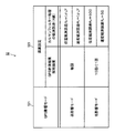
- the calculation setting table 52 is a table in which calculation settings are defined, and an example of the table configuration is shown in FIG.
- the calculation setting table 52 stores a GPS influence mode 521 and a calculation setting 523 in association with each other.
- “every time” first frequency
- second frequency once every 10 times
- the GPS influence mode when the GPS influence mode is set to the high influence mode (first degree), the GPS calculation result is adopted every time and the coupling process is executed. On the other hand, when the GPS influence mode is set to the low influence mode (second degree), the GPS calculation result is adopted once every 10 times and the coupling process is executed.
- the observation error (R value) includes a position observation error “R P ” that is a position observation error and a velocity observation error “R V ” that is a velocity observation error.
- R P ( ⁇ P ) 2
- R V ( ⁇ V ) 2
- first parameter value the position observation error
- second parameter value the velocity observation error
- ⁇ P and “ ⁇ V ” are a position error and a speed error included in the GPS calculation result.
- a value of about “10” is set as the position observation error “R P ”
- a value of about “0.5” is set as the speed observation error “R V ”. Therefore, in the low influence mode, a larger value than the high influence mode is set as the observation error “R”.
- the mode setting condition table 53 is a table in which conditions for setting the GPS influence mode are defined.
- the first mode setting condition table and the second mode setting condition table include.
- the setting mode 54 is a set GPS influence mode, and is updated as needed by the influence mode setting process.
- FIG. 14 is a flowchart showing a flow of first navigation processing that is an example of navigation processing executed by the processing unit 10 in accordance with the navigation program 51 stored in the storage unit 50.
- the processing unit 10 starts acquiring the GPS measurement information 55 and the INS measurement information 56 from the GPS unit 3 and the INS unit 5 (step A1). And the process part 10 performs a movement condition determination process (step A3). Specifically, for example, whether the vehicle is stopped or moving based on the acceleration (acceleration vector) or angular velocity of the vehicle acquired as the INS measurement information 56 from the INS unit 5. Determine.
- the processing unit 10 performs GPS calculation processing (step A5). Specifically, using the GPS measurement information 55 acquired from the GPS unit 3, a known positioning calculation is performed to calculate the position and speed (speed vector) of the automobile. Also, a known error estimation calculation is performed to estimate position and speed (speed vector) errors. Then, these calculation results are stored in the storage unit 50 as the GPS calculation result 57.
- the processing unit 10 performs INS calculation processing (step A7). Specifically, using the INS measurement information 56 acquired from the INS unit 5, a known inertial navigation calculation is performed to calculate the position, speed (speed vector), and attitude angle of the automobile. Then, these calculation results are stored in the storage unit 50 as the INS calculation result 58.
- the processing unit 10 performs the influence mode setting process described with reference to FIG. 6 according to the influence mode setting program 511 stored in the storage unit 50 (step A9). And the process part 10 performs a coupling process according to the coupling program 513 memorize
- FIG. 15 is a flowchart showing the flow of the coupling process.
- the processing unit 10 determines whether or not the GPS calculation result 57 is adopted for the coupling process (step B1). Specifically, based on the GPS measurement result adoption frequency associated with the GPS influence mode set in the influence mode setting process, it is determined whether or not the GPS calculation result 57 is adopted in the current coupling process.
- the processing unit 10 sets an observation amount vector “Z” using the latest GPS calculation result 57 as an observation amount (step B3). ). Further, the calculation setting table 52 is referred to, and the observation error covariance matrix “R” is set based on the observation error corresponding to the setting mode 54 (step B5). Then, the processing unit 10 performs Kalman filter processing using the observation vector “Z” and the observation error covariance matrix “R” set in Steps B3 and B5 (Step B7).
- step B1 determines whether the GPS calculation result 57 is not employed for the coupling process. If it is determined in step B1 that the GPS calculation result 57 is not employed for the coupling process (step B1; No), the processing unit 10 determines the movement status determined in step A3 (step B9).
- the processing unit 10 sets the movement time restricted speed vector as the observation amount vector “Z” (step B11). Also, an observation error covariance matrix “R” is set based on the moving speed observation error (for example, a predetermined value) (step B13). Then, the processing unit 10 performs Kalman filter processing using the observation vector “Z” and the observation error covariance matrix “R” set in Steps B11 and B13 (Step B7).
- the processing unit 10 sets the stop-time restricted speed vector as the observation vector “Z” (step B15). Further, an observation error covariance matrix “R” is set based on the stop speed observation error (for example, a predetermined value) (step B17). Then, the processing unit 10 performs Kalman filter processing using the observation vector “Z” and the observation error covariance matrix “R” set in Steps B15 and B17 (Step B7).
- the processing unit 10 stores the result as the coupling result 59 in the storage unit 50. Then, the processing unit 10 ends the coupling process.
- the processing unit 10 outputs the coupling result 59 (step A13). For example, map matching processing is performed on the position (coupling position) obtained as the coupling result 59, and the display of the navigation screen of the display unit 30 is updated with the result.
- the processing unit 10 determines whether or not to end the processing (step A15). For example, when a navigation end instruction operation is performed by the user via the operation unit 20, it is determined that the navigation process is to be ended. When it determines with not complete
- the influence degree setting unit 7 performs the INS of the GPS measurement result until the given condition is satisfied after the position calculation is started. After the degree of influence on the measurement result is set to the first degree and the given condition is satisfied, the degree of influence is set to a second degree lower than the first degree. And the coupling process part 9 performs the coupling process of a GPS measurement result and an INS measurement result based on the influence degree set by the influence degree setting part 7, and calculates the position of a moving body.
- the influence degree setting unit 7 includes an influence mode setting unit 7A. And, the first mode setting condition determined based on (1) the initial calculation accuracy of GPS, (2) the elapsed time from the start of position calculation or the number of times of position calculation, and the first determined based on the accuracy of the coupling result
- the GPS influence mode for determining the GPS influence degree is set using the mode setting condition of 2.
- the coupling processing unit 9 has a Kalman filter processing unit 9A, and the calculation setting is changed according to the GPS influence mode set by the influence mode setting unit 7A to perform the Kalman filter processing.
- the calculation setting includes an execution frequency of executing the coupling process using the GPS measurement result, and the execution frequency is set lower in the low influence mode than in the high influence mode.
- the calculation setting includes an observation error (R value) that is an assumed error of the GPS measurement result as an observation amount, and a larger value is set in the low influence mode than in the high influence mode.
- the degree of influence of the measurement result of the satellite positioning unit on the measurement result of the inertial positioning unit is set high, and after the given condition is met, By setting the influence degree to be low, it is possible to optimize the influence degree particularly during the initial operation of the position calculation device. Then, by changing the calculation setting of the coupling process according to the degree of influence, it is possible to improve the effectiveness of the coupling process, and more accurately calculate the position.
- GPS unit to which GPS is applied has been described as an example of the satellite positioning unit.
- WAAS Wide Area Augmentation System
- QZSS Quadrati Zenith Satellite System
- GLONASS GLObal NAvigation Satellite System
- a unit to which another satellite positioning system such as GALILEO is applied may be used.
- the INS unit is described as an example of the inertial positioning unit.
- an inertial sensor or an inertial measurement unit (IMU) that measures INS measurement information (acceleration or angular velocity) is used as the inertial positioning unit. It is good.
- the processing unit of the position calculation device may be configured to perform the INS calculation process using the INS measurement information measured by the inertial positioning unit.
- the Kalman filter process is described as an example of the coupling process, but the coupling process is not limited thereto.
- an average process for calculating an average of the GPS measurement result and the INS measurement result may be included in the coupling process.
- a simple arithmetic average or geometric average may be applied, or a weighted average may be applied. If an arithmetic average or a geometric average is applied, for example, the execution frequency of executing the average process using the GPS measurement result can be determined as the calculation setting of the coupling process. In the high influence mode, the execution frequency is increased to make the GPS measurement result easily affect the INS measurement result. In the low influence mode, the execution frequency is decreased to make the GPS measurement result difficult to affect the INS measurement result. Good.
- a weighted average weight can be set as a calculation setting for the coupling process.
- the weight of the GPS measurement result is set to be large so that the GPS measurement result is weighted and averaged over the INS measurement result.
- the INS measurement result is weighted more than the GPS measurement result. What is necessary is just to set the weight of a GPS measurement result small so that it may average.
- the GPS influence mode is set using both the first mode setting condition and the second mode setting condition.
- the first mode setting condition is used alone.
- the GPS influence mode may be set using the second mode setting condition, or the GPS influence mode may be set using the second mode setting condition alone.
- the first mode setting condition is defined as a condition combining (1) GPS initial calculation accuracy and (2) elapsed time from the start of position calculation or the number of times of position calculation.
- (2) may be defined as individual conditions. That is, (1) the GPS influence mode may be set using a condition based on the GPS initial calculation accuracy alone, or (2) a condition based on the elapsed time from the start of position calculation or the number of position calculations is used alone. A GPS influence mode may be set.
- processing unit 10 of the electronic device has been described as performing GPS calculation processing using the GPS measurement information 55 acquired from the GPS unit 3. Further, the processing unit 10 has been described as performing the INS calculation process using the INS measurement information 56 acquired from the INS unit 5. That is, it has been described that the execution subject of the GPS calculation process, the INS calculation process, and the coupling process are all the processing unit 10 of the electronic device. This configuration may be as follows.
- the GPS unit 3 performs a GPS calculation process using the GPS measurement information 55 to obtain a GPS calculation result 57 and outputs it to the processing unit 10. Further, the INS unit 5 performs an INS calculation process using the INS measurement information 56 to obtain an INS calculation result 58 and outputs the result to the processing unit 10.
- the process part 10 performs the coupling process with the GPS calculation result 57 and the INS calculation result 58 acquired from each unit. That is, in this case, the execution body of the GPS calculation process and the INS calculation process is the GPS unit 3 and the INS unit 5, respectively, and the execution body of the coupling process is the processing unit 10 of the electronic device.
- Position Calculation Method The position of the moving body may be calculated by applying a position calculation method that matches the set influence mode (influence degree). For example, when the GPS influence mode is the high influence mode, the position is calculated by executing a predetermined position calculation process using the GPS measurement result. When the GPS influence mode is the low influence mode, the GPS measurement result and the INS measurement are calculated. The position may be calculated by executing a coupling process using the result.
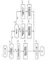
- FIG. 16 is a flowchart showing a flow of a second navigation process executed in this case by the processing unit 10 instead of the first navigation process of FIG.
- the processing unit 10 determines the mode (setting mode 54) set in the influence mode setting process (step C10).
- step C10 When it is determined that the setting mode 54 is the high influence mode (step C10; high influence mode), the processing unit 10 performs a GPS calculation result filtering process (step C17). Then, the processing unit 10 outputs the filtering result (step C19).
- step C10 low influence mode
- the processing unit 10 performs the coupling process described with reference to FIG. 15 (step A11). Then, the processing unit 10 outputs the coupling result 59 (Step A13).
- the GPS calculation result filtering process in step C17 is a position calculation process for calculating a more probable position by filtering the GPS calculation result obtained in the GPS calculation process in step A5.
- a filtering method in this case various methods can be applied. For example, a Kalman filter process may be applied, or a filtering process based on a past history of GPS calculation results may be applied.
- Kalman filter processing for example, the GPS calculation result is set as the control input “U”, and the moving speed constraint condition and the stopping speed constraint condition described in the above embodiment are set as the observation amount “Z”.
- a method of estimating the state “X” such as the position and speed of the body is applicable.
- the GPS calculation results for the past predetermined period for example, the past 10 seconds
- the position of the moving object A method for estimating the speed and the like can be applied.
- the present invention can be similarly applied to electronic devices other than navigation.
- the present invention can be similarly applied to other electronic devices such as a mobile phone, a personal computer, and a PDA (Personal Digital Assistant), and position calculation of the electronic device can be realized.
- PDA Personal Digital Assistant
Landscapes
- Engineering & Computer Science (AREA)
- Radar, Positioning & Navigation (AREA)
- Remote Sensing (AREA)
- Physics & Mathematics (AREA)
- General Physics & Mathematics (AREA)
- Computer Networks & Wireless Communication (AREA)
- Automation & Control Theory (AREA)
- Position Fixing By Use Of Radio Waves (AREA)
- Navigation (AREA)
Abstract
衛星測位用ユニット及び慣性測位用ユニットを備えた移動体の位置算出装置において、位置算出開始から所与の条件が成立するまでの間は、慣性測位用ユニットによる計測結果2に対する、衛星測位用ユニットによる計測結果1の影響度合を第1の度合に設定し、所与の条件が成立した後は、影響度合を第2の度合に設定する。そして、設定された影響度合に基づいて計測結果1と計測結果2とのカップリング処理を実行して、移動体の位置を算出する。
Description
本発明は、移動体に備えられた衛星測位用ユニット及び慣性測位用ユニットの計測結果を用いた位置算出方法等に関する。
いわゆるシームレス測位やモーションセンシング、姿勢制御など様々な分野において、慣性センサーの活用が注目されている。慣性センサーとしては、加速度センサーやジャイロセンサー、圧力センサー、地磁気センサーなどが広く知られている。慣性センサーの検出結果を利用して慣性航法演算を行う慣性航法システム(以下、「INS(Inertial Navigation System)」と称する。)も考案されている。
INSでは、慣性センサーの検出結果に含まれ得る種々の誤差成分に起因して位置算出の正確性が低下するという問題があり、位置算出の正確性を向上させるための様々な技術が考案されている。例えば、特許文献1には、INS演算結果を、GPS(Global Positioning System)を利用して補正する技術が開示されている。
GPSを利用してINS演算結果を補正する技術は、GPS演算結果が正しいことを前提としている。特許文献1に開示された技術も同様である。しかし、GPS演算結果は、GPS衛星から受信したGPS衛星信号の信号強度、受信環境、GPS衛星の天空配置、マルチパスといった種々の要因により、演算結果の精度が低下する場合がある。このため、常にGPS演算結果を利用してINS演算結果を補正することが、必ずしも位置算出の精度改善に繋がるとは限らなかった。
本発明は上述した課題に鑑みて為されたものであり、移動体に備えられた衛星測位用ユニット及び慣性測位用ユニットの計測結果を併用して、移動体の位置をより正確に算出するための手法を提案することを目的とする。
以上の課題を解決するための第1の形態は、移動体に備えられた衛星測位用ユニットの第1の計測結果と、前記移動体に備えられた慣性測位用ユニットの第2の計測結果とを用いて、前記移動体の位置を算出する位置算出方法であって、位置算出を開始してから所与の条件が成立するまでの間は、前記第1の計測結果の前記第2の計測結果に対する影響度合を第1の度合に設定し、前記条件が成立した後は、前記影響度合を前記第1の度合よりも低い第2の度合に設定することと、前記影響度合に基づき、前記第1の計測結果と前記第2の計測結果とのカップリング処理を実行して前記移動体の位置を算出することと、を含む位置算出方法である。
また、他の形態として、移動体に備えられた衛星測位用ユニットの第1の計測結果と、前記移動体に備えられた慣性測位用ユニットの第2の計測結果とを用いて、前記移動体の位置を算出する位置算出装置であって、位置算出を開始してから所与の条件が成立するまでの間は、前記第1の計測結果の前記第2の計測結果に対する影響度合を第1の度合に設定し、前記条件が成立した後は、前記影響度合を前記第1の度合よりも低い第2の度合に設定する影響度合設定部と、前記影響度合に基づき、前記第1の計測結果と前記第2の計測結果とのカップリング処理を実行して前記移動体の位置を算出するカップリング処理部と、を備えた位置算出装置を構成してもよい。
この第1の形態等によれば、位置算出を開始してから所与の条件が成立するまでの間は、第1の計測結果の第2の計測結果に対する影響度合を第1の度合に設定する。所与の条件が成立した後は、影響度合を第1の度合よりも低い第2の度合に設定する。つまり、所与の条件の成立前後で、慣性測位用ユニットの計測結果に対する衛星測位用ユニットの計測結果の影響度合を変更する。これにより、特に初期動作時における影響度合の適正化を実現することができる。適正化した影響度合に基づき第1の計測結果と第2の計測結果とのカップリング処理を実行することで、位置算出の正確性を向上させることができる。
また、第2の形態として、第1の形態の位置算出方法において、前記影響度合には、前記第1の計測結果を採用して前記カップリング処理を実行する実行頻度が含まれており、前記第1の度合に設定することは、前記実行頻度を第1の頻度に設定することを含み、前記第2の度合に設定することは、前記実行頻度を前記第1の頻度よりも低い第2の頻度に設定することを含み、前記位置を算出することは、前記実行頻度に従って前記第1の計測結果を採用した前記カップリング処理を実行することを含む、位置算出方法を構成することとしてもよい。
この第2の形態によれば、所与の条件が成立するまでの間は、第1の計測結果を採用してカップリング処理を実行する実行頻度を第1の頻度に設定する。所与の条件が成立した後は、実行頻度を第1の頻度よりも低い第2の頻度に設定する。つまり、所与の条件が成立した後は、第1の計測結果をカップリング処理に採用する頻度を下げて、第1の計測結果の第2の計測結果に対する影響度合を低くする。これにより、衛星測位用ユニットの計測結果をカップリング処理に採用する頻度を適正化し、カップリング処理の実効性を高めることができる。
また、第3の形態として、第1の形態の位置算出方法において、前記カップリング処理は、前記第1の計測結果を観測量とするカルマンフィルター処理を含み、前記影響度合には、前記カルマンフィルター処理に用いる誤差パラメーター値が含まれており、前記第1の度合に設定することは、前記誤差パラメーター値を第1のパラメーター値に設定することを含み、前記第2の度合に設定することは、前記誤差パラメーター値を前記第1のパラメーター値よりも大きい第2のパラメーター値に設定することを含み、前記位置を算出することは、前記第1の計測結果及び前記誤差パラメーター値を用いて前記カルマンフィルター処理を実行することを含む、位置算出方法を構成することとしてもよい。
この第3の形態によれば、所与の条件が成立するまでの間は、カルマンフィルター処理に用いる誤差パラメーター値を第1のパラメーター値に設定する。所与の条件が成立した後は、誤差パラメーター値を第1のパラメーター値よりも大きい第2のパラメーター値に設定する。誤差パラメーター値は、例えば、カルマンフィルター処理において第1の計測結果を重視する程度を決定付ける値である。誤差パラメーター値を大きく設定することは、第1の計測結果の第2の計測結果に対する影響度合を下げることに相当する。誤差パラメーター値を適正化することで、算出される移動体の位置の正確性が向上する。
また、第4の形態として、第1の形態の位置算出方法において、前記位置を算出することは、前記影響度合が前記第1の度合の場合に前記第1の計測結果を用いた所定の位置算出処理を実行して位置を算出し、前記影響度合が前記第2の度合の場合に前記カップリング処理を実行して位置を算出することである、位置算出方法を構成することとしてもよい。
この第4の形態によれば、影響度合が第1の度合の場合は、第1の計測結果を用いた所定の位置算出処理を実行して位置を算出する。他方、影響度合が第2の度合の場合は、カップリング処理を実行して位置を算出する。これにより、影響度合に見合った位置算出の方式を適用して移動体の位置を算出することが可能となる。
また、第5の形態として、第1~第3の何れかの形態の位置算出方法において、前記影響度合を設定することは、位置算出を開始してからの経過時間又は位置算出回数が、前記位置算出の結果の精度が安定するための時間的条件として定められた精度安定条件を満たす場合に、前記所与の条件が成立したと判定することを含む、位置算出方法を構成することとしてもよい。
この第5の形態によれば、位置算出を開始してからの経過時間又は位置算出回数が、位置算出の結果の精度が安定するための時間的条件として定められた精度安定条件を満たす場合に、第1の計測結果の第2の計測結果に対する影響度合を、第1の度合から第2の度合に低下させる。これにより、位置算出の結果の精度が安定したと判断した後は、衛星測位用ユニットの計測結果への依存度を下げて位置算出を行うことが可能となる。
また、第6の形態として、第1~第3の何れかの形態の位置算出方法において、前記位置を算出することは、位置算出の開始時に、前記第1の計測結果から求められた位置を以降の位置算出の基準位置とすることを含み、前記影響度合を設定することは、位置算出の開始時の前記第1の計測結果が所定の精度良好条件を満たす場合に、前記所与の条件が成立したと判定することを含む、位置算出方法を構成することとしてもよい。
この第6の形態によれば、位置算出の開始時に、第1の計測結果から求められた位置を基準位置として以降の位置算出を行う。つまり、第1の計測結果の精度が良好であれば、真の位置に近い位置を基準位置として以降の位置算出を行うことができる。そこで、位置算出の開始時の第1の計測結果が所定の精度良好条件を満たす場合には、影響度合を第1の度合から第2の度合に低下させる。これにより、信頼性の高い基準位置が得られたと判断できる場合には、衛星測位用ユニットの計測結果への依存度を下げて位置算出を行うことが可能となる。
また、第7の形態として、第1~第3の何れかの形態の位置算出方法において、前記影響度合を設定することは、前記カップリング処理の結果が所定の精度良好条件を満たす場合に、前記所与の条件が成立したと判定することを含む、位置算出方法を構成することとしてもよい。
この第7の形態によれば、カップリング処理の結果が所定の精度良好条件を満たす場合は、影響度合を第1の度合から第2の度合に低下させる。これにより、カップリング処理の結果の精度が良好であると判断できる場合には、衛星測位用ユニットの計測結果への依存度を下げて位置算出を行うことが可能となる。
以下、図面を参照して、本発明の好適な実施形態の一例について説明する。本実施形態は、衛星測位システムの一種であるGPS(Global Positioning System)と、慣性航法演算を行うシステムであるINS(Inertial Navigation System)とを併用して位置算出を行う実施形態である。
1.原理
1-1.構成
図1は、本実施形態における位置算出装置1の主要構成図である。位置算出装置1は、移動体に備えられて、当該移動体の位置を算出する装置(位置算出システム)である。移動体は、自動車やオートバイ、自転車、船、電車といった物の他、人間自体であってもよい。人間が位置算出装置1を携帯し、人間自身が位置算出装置1を備えることとしてもよい。図1では、ユニット(モジュール)を二重線で図示し、ユニットの計測結果を利用して演算処理を行う処理ブロックを一重線で図示することで、両者を区別する。図2についても同様である。
1-1.構成
図1は、本実施形態における位置算出装置1の主要構成図である。位置算出装置1は、移動体に備えられて、当該移動体の位置を算出する装置(位置算出システム)である。移動体は、自動車やオートバイ、自転車、船、電車といった物の他、人間自体であってもよい。人間が位置算出装置1を携帯し、人間自身が位置算出装置1を備えることとしてもよい。図1では、ユニット(モジュール)を二重線で図示し、ユニットの計測結果を利用して演算処理を行う処理ブロックを一重線で図示することで、両者を区別する。図2についても同様である。
位置算出装置1は、ユニット(モジュール)として、GPSユニット3と、INSユニット5とを備える。また、位置算出装置1は、主要な処理ブロックとして、影響度合設定部7と、カップリング処理部9とを有する。
GPSユニット3は、衛星測位システムを利用して測位を行うためのユニット(衛星測位用ユニット)である。GPSユニット3は、GPS衛星から発信されているGPS衛星信号を受信するアンテナや、受信したGPS衛星信号を処理するプロセッサー等を有して構成される。
GPSユニット3は、GPS衛星信号のコード位相やドップラー周波数、擬似距離、擬似距離変化率等のGPSメジャメント情報を計測可能に構成されている。また、GPSユニット3は、GPSメジャメント情報を用いたGPS演算を行って、移動体の位置や速度(速度ベクトル)等を計測可能に構成されている。GPSメジャメント情報やGPS演算結果は、GPS計測結果(第1の計測結果)としてカップリング処理部9に出力される。
INSユニット5は、慣性航法を利用して測位を行うためのユニット(慣性測位用ユニット)である。INSユニット5は、加速度センサーやジャイロセンサー等の慣性センサーや、慣性センサーをパッケージ化した慣性計測ユニット(IMU(Inertial Measurement Unit))、慣性センサーの計測結果を処理するプロセッサー等を有して構成される。
INSユニット5は、慣性センサーの計測結果を用いて、移動体の加速度(加速度ベクトル)や角速度等をINSメジャメント情報として計測可能に構成されている。また、INSユニット5は、INSメジャメント情報を用いた慣性航法演算(INS演算)を行って、移動体の位置や速度(速度ベクトル)、姿勢角等を計測可能に構成されている。INSメジャメント情報やINS演算結果は、INS計測結果(第2の計測結果)としてカップリング処理部9に出力される。
影響度合設定部7は、GPS計測結果(第1の計測結果)のINS計測結果(第2の計測結果)に対する影響度合を設定する。影響度合設定部7は、位置算出を開始してから所与の条件が成立したか否かを判定する。そして、所与の条件が成立するまでの間は、GPS計測結果のINS計測結果に対する影響度合を第1の度合に設定し、条件が成立した後は、影響度合を第1の度合よりも低い第2の度合に設定する。
カップリング処理部9は、影響度合設定部7により設定された影響度合に基づいて、GPS計測結果(第1の計測結果)とINS計測結果(第2の計測結果)とのカップリング処理を実行して移動体の位置等を算出する。
図2は、図1の位置算出装置1を適用した第1の位置算出装置1Aの構成図である。第1の位置算出装置1Aでは、図1の影響度合設定部7が影響モード設定部7Aを有し、カップリング処理部9がカルマンフィルター処理部9Aを有する。
影響モード設定部7Aは、後述するモード設定条件に従ってGPS影響モードを設定する。GPS影響モードは、GPSの影響度合を決定づけるモードである。本実施形態では、GPS計測結果のINS計測結果に対する影響度合が比較的高いモードである「高影響モード」と、GPS計測結果のINS計測結果に対する影響度合が比較的低いモードである「低影響モード」との2種類のモードを択一的に設定する場合を想定する。なお、初期設定では、高影響モードを設定することとする。
カルマンフィルター処理部9Aは、GPS計測結果を観測量“Z”とするカルマンフィルター処理を実行して、GPS計測結果とINS計測結果とをカップリング(結び付け)する。具体的には、カルマンフィルターの理論に基づき、予測演算(時刻更新)と補正演算(観測更新)とを行って、移動体の状態“X”を推定する。
本実施形態において、移動体の状態“X”には、少なくとも移動体の位置が含まれる。予測演算では、例えば、INSユニット5から入力したINS計測結果を制御入力“U”として、1つ前の時刻(前回時刻)における状態補正値“X+”から、現在の時刻(今回時刻)における状態“X”を予測する演算を行って、状態予測値“X-”を算出する。
補正演算では、例えば、GPSユニット3から入力したGPS計測結果を観測量“Z”として用いて、予測演算で算出した状態予測値“X-”を補正する演算を行って、状態補正値“X+”を算出する。そして、算出した状態補正値“X+”を、カップリング結果として出力する。
また、カルマンフィルター処理部9Aは、GPS計測結果とは別に、移動体の運動モデルに基づく制約条件を観測量“Z”として適用可能に構成されている。本実施形態では、移動体の停止時における速度制約条件である「停止時速度制約条件」と、移動体の移動時における速度制約条件である「移動時速度制約条件」との2種類の速度制約条件を適用する場合を想定する。
停止時速度制約条件(第1の制約条件)は、移動体の停止時に適用可能な制約条件である。移動体が停止しているのであれば、理想的には移動体の速度はゼロである。従って、移動体が停止していると判定した場合は「移動体の各軸の速度成分=0(速度ベクトル=ゼロベクトル)」を観測量“Z”として与えることができる。
移動時速度制約条件(第2の制約条件)は、移動体の移動時に適用可能な制約条件である。例えば、移動体として四輪自動車を想定した場合、通常、四輪自動車はジャンプや横滑りすることはないと仮定することができる。従って、移動体が移動していると判定した場合は「移動体の縦横方向の速度成分=0」を観測量“Z”として与えることができる。
本実施形態では、GPS計測結果と上記の制約条件(停止時速度制約条件又は移動時速度制約条件)とを切り替えて観測量“Z”に適用する場合を一例として説明する。なお、本実施形態とは異なり、GPS計測結果と上記の制約条件とを観測量“Z”として併用することも当然に可能である。
図3は、カルマンフィルター処理の入出力データの説明図である。制御入力“U”と、観測量“Z”と、状態“X”との対応関係を表したテーブルを図示している。カップリングには種々の方式が存在する。その中でも、ルーズカップリング(疎結合)と呼ばれる方式と、タイトカップリング(密結合)と呼ばれる方式とが一般的に用いられる。
ルーズカップリング方式は、GPSとINSとの結び付きが比較的弱いカップリング方式である。この方式では、例えば、制御入力“U”をINS演算結果(位置、速度、姿勢角等)とし、観測量“Z”をGPS演算結果(位置、速度等)としてカップリング処理を実行する。そして、移動体情報(位置、速度、姿勢角等)を状態“X”として推定する。
タイトカップリング方式は、GPSとINSとの結び付きが比較的強いカップリング方式である。この方式では、例えば、制御入力“U”をINS演算結果(位置、速度、姿勢角等)とし、観測量“Z”をGPSメジャメント情報(コード位相、ドップラー周波数、擬似距離、擬似距離変化率等)としてカップリング処理を実行する。そして、移動体情報(位置、速度、姿勢角等)を状態“X”として推定する。
また、タイトカップリング方式として、制御入力“U”をINSメジャメント情報(加速度、角速度等)とし、観測量“Z”をGPSメジャメント情報(コード位相、ドップラー周波数、擬似距離、擬似距離変化率等)とし、状態“X”を移動体情報(位置、速度、姿勢角等)とする手法も存在する。
本実施形態の位置算出方法は、上記の何れのカップリング方式に対しても実質的に同一に適用可能である。つまり、GPS計測結果(第1の計測結果)として、GPSメジャメント情報を適用してもよいし、GPS演算結果を適用してもよい。また、INS計測結果(第2の計測結果)として、INSメジャメント情報を適用してもよいし、INS演算結果を適用してもよい。
INS計測結果及びGPS計測結果として用いる情報は、適用するシステムに応じて適宜設定可能である。この場合、カルマンフィルター処理の予測演算及び補正演算で用いる演算式やパラメーター値を、適用するシステムに応じて適宜設定すればよい。なお、具体的な演算式やパラメーター値については、公知の手法に基づき定義可能であるため、ここでは説明を省略する。
1-2.GPS影響モードの設定
図4は、GPS影響モードの設定に用いる第1のモード設定条件の説明図であり、第1のモード設定条件を定めた第1のモード設定条件テーブルを図示したものである。第1のモード設定条件テーブルには、第1のモード設定条件と、設定モードとが対応付けて定められている。
図4は、GPS影響モードの設定に用いる第1のモード設定条件の説明図であり、第1のモード設定条件を定めた第1のモード設定条件テーブルを図示したものである。第1のモード設定条件テーブルには、第1のモード設定条件と、設定モードとが対応付けて定められている。
第1のモード設定条件は、(1)GPS初回演算精度、(2)位置算出を開始してからの経過時間又は位置算出回数、に基づいて定められた条件である。GPS初回演算精度は、GPSユニット3の初回の演算結果の精度である。
1番目の条件は「GPS初回演算精度=良好」である。そして、この条件を満たす場合の設定モードとして「低影響モード」が定められている。つまり、「GPS初回演算精度=良好」の場合は、GPS影響モードを初期設定である「高影響モード」から「低影響モード」に切り替える。この1番目の条件は、位置算出の開始時のGPS計測結果(第1の計測結果)が所定の精度良好条件を満たすことに相当する。そして、精度良好条件を満たす場合には、GPS計測結果のINS計測結果に対する影響度合を、初期設定である第1の度合(高影響モード)から、第1の度合よりも低い第2の度合(低影響モード)に下げることに相当する。
2番目の条件は「GPS初回演算精度=非良好」である。この2番目の条件は、さらに位置算出開始からの経過時間又は位置算出回数に応じて分けられている。経過時間≦精度安定時間“θT”、又は、位置算出回数≦精度安定回数“θC”、の条件を満たす場合の設定モードとして「高影響モード」が定められている。また、経過時間>精度安定時間“θT”、又は、位置算出回数>精度安定回数“θC”、の条件を満たす場合の設定モードとして「低影響モード」が定められている。つまり、「GPS初回演算精度=非良好」の場合は、GPS影響モードを初期設定である「高影響モード」のままとし、ある程度時間が経過した時点で「低影響モード」に切り替える。
位置算出開始からの経過時間が所定の精度安定時間“θT”を超えること、又は、位置算出回数が所定の精度安定回数“θC”を超えることは、位置算出を開始してからの経過時間又は位置算出回数が、位置算出の結果の精度が安定するための時間的条件として定められた精度安定条件を満たすことに相当する。そして、この精度良好条件を満たす場合には、GPS計測結果のINS計測結果に対する影響度合を、当初設定した第1の度合(高影響モード)から、第1の度合よりも低い第2の度合(低影響モード)に下げることに相当する。
なお、精度安定時間“θT”や精度安定回数“θC”は、本実施形態の位置算出方法を適用するシステムに応じて適宜設定可能である。例えば、位置算出を「1秒間隔」で行うシステムに適用するのであれば、“θT”として「30秒~60秒」の範囲の秒数、“θC”として「30回~60回」の範囲の回数を設定すると効果的である。
GPS演算では、各GPS衛星それぞれについて観測した擬似距離を利用して、例えば最小二乗法を適用した測位計算を行って移動体の位置を算出する。また、受信したGPS衛星信号の受信周波数の誤差(搬送波周波数からの周波数ズレ)に基づいてGPS衛星と移動体との相対速度(相対速度ベクトル)を算出し、これを用いて移動体の速度(速度ベクトル)を算出する。この際、公知の誤差推定演算を行うことで、算出した位置や速度(速度ベクトル)に含まれ得る最大の誤差を推定することができる。
そこで、上記の誤差推定演算で推定される誤差に対する閾値を予め定めておく。例えば、位置誤差の閾値として“10[m]”、速度誤差の閾値として“1[m/s]”を定めておく。そして、位置誤差及び速度誤差に対する閾値判定をそれぞれ行って、GPS初回演算精度を判定する。この場合には、それぞれの閾値判定結果に対してAND条件を適用してGPS初回演算精度を判定してもよいし、OR条件を適用してGPS初回演算精度を判定してもよい。
GPSの初回演算精度が良好であるにも関わらずGPS影響モードを「低影響モード」に設定することや、GPSの初回演算精度が非良好であるにも関わらずGPS影響モードを「高影響モード」に設定することは、一見矛盾しているようにも思われる。しかし、敢えてこのような設定方法を採用したのには理由がある。
慣性航法演算を利用した位置算出を行う際には、基準位置や基準方位が必要となる。そのため、例えば、位置算出の開始時にGPS演算処理を行い、得られた位置及び方位を以降の位置算出の基準位置及び基準方位とすることが、1つの手法として考えられる。
GPS初回演算精度が良好であれば、精度の高い位置や方位を基準として以降の位置算出を行うことができる。そのため、GPSの影響度合を下げてINSに依存して位置算出を行っても、暫くの間は、比較的精度の高い安定した演算結果を得ることができる。
ところが、GPS初回演算精度が良好でない場合は、精度の低い位置や方位を基準として以降の位置算出を行わなければならなくなる。つまり、当初から誤差が重畳された状態で位置算出を開始することになる。この場合、GPSの影響度合を下げてINSに依存してしまうと、当初の誤差分がいつまで経っても補正されなくなる。
そこで、GPSの初回演算精度が良好である場合は、GPS影響モードを「低影響モード」に設定し、GPSの初回演算精度が非良好である場合は、GPS影響モードを「高影響モード」に設定する。GPS影響モードを「高影響モード」に設定した状態で位置算出を行っていくと、GPSの演算精度が改善されるのに伴い、当初の誤差分が次第に補正されていく。そこで、ある程度の時間が経過した時点で、GPS影響モードを「高影響モード」から「低影響モード」に切り替えることで、GPSへの依存度を低くする。
図5は、GPS影響モードの設定に用いる第2のモード設定条件の説明図であり、第2のモード設定条件を定めた第2のモード設定条件テーブルを図示したものである。第2のモード設定条件テーブルには、第2のモード設定条件と、設定モードとが対応付けて定められている。
第2のモード設定条件は、カップリング処理の結果に基づき定義される条件である。具体的には、1番目の条件として「カップリング結果精度=良好」が定められている。そして、この1番目の条件を満たす場合の設定モードとして「低影響モード」が定められている。また、2番目の条件として「カップリング結果精度=非良好」が定められている。そして、この2番目の条件を満たす場合の設定モードとして「高影響モード」が定められている。
カップリング結果精度は、カップリング処理を行うことで得られた移動体の位置等の精度のことを意味する。例えば、カルマンフィルター処理では、推定対象とする状態“X”の誤差“P”を設定して演算を行う。予測演算及び補正演算において、状態“X”と併せて誤差“P”の予測及び補正を行うことで、状態“X”の精度が定まる。従って、カルマンフィルター処理で用いる誤差“P”を、カップリング結果精度として利用することができる。
状態“X”が複数の要素で構成される場合は、誤差“P”は行列形式の誤差共分散行列 “P”で表すことができる。この場合、誤差共分散行列“P”の対角成分から、各要素の精度を見積もることができる。例えば、状態“X”の要素が移動体の位置、速度及び姿勢角であれば、誤差共分散行列“P”の対角成分が、それぞれカップリング位置誤差、カップリング速度誤差及びカップリング姿勢角誤差となる。
そこで、カップリング位置誤差、カップリング速度誤差及びカップリング姿勢角誤差に対する閾値を予め定めておく。例えば、カップリング位置誤差の閾値として“10[m]”、カップリング速度誤差の閾値として“1[m/s]”、カップリング姿勢角誤差の閾値として“1[°]”を定めておく。そして、それぞれに対する閾値判定を行って、カップリング結果精度を判定する。この場合には、それぞれの閾値判定結果に対してAND条件を適用してカップリング結果精度を判定してもよいし、OR条件を適用してカップリング結果精度を判定してもよい。
図6は、本実施形態における影響モード設定処理の流れを示すフローチャートである。最初に、影響モード設定部7Aは、図4の第1のモード設定条件テーブルを参照して、第1のモード設定条件の成否を判定する(ステップS1)。その判定結果(第1の判定結果)が高影響モードであれば(ステップS3;高影響モード)、影響モード設定部7Aは、図5の第2のモード設定条件テーブルを参照して、第2のモード設定条件の成否を判定する(ステップS5)。
ステップS5における判定結果(第2の判定結果)が高影響モードであれば(ステップS7;高影響モード)、影響モード設定部7Aは、GPS影響モードを高影響モードに設定する(ステップS9)。一方、ステップS1における第1の判定結果が低影響モードである場合(ステップS3;低影響モード)、又は、ステップS5における第2の判定結果が低影響モードである場合は(ステップS7;低影響モード)、影響モード設定部7Aは、GPS影響モードを低影響モードに設定する(ステップS11)。そして、影響モード設定処理を終了する。
この影響モード設定処理では、第1の判定結果及び第2の判定結果が両方とも高影響モードである場合に限り、GPS影響モードを高影響モードに設定することにしている。これには、なるべく早い段階でGPSの影響度合を下げて位置算出を行おうとする狙いがある。
1-3.演算設定
カップリング処理部9は、GPS影響モードに応じて演算設定を変更してカップリング処理を行う。本実施形態において、演算設定には、GPS計測結果採用頻度と、カルマンフィルター処理で用いる誤差パラメーター値とが含まれる。
カップリング処理部9は、GPS影響モードに応じて演算設定を変更してカップリング処理を行う。本実施形態において、演算設定には、GPS計測結果採用頻度と、カルマンフィルター処理で用いる誤差パラメーター値とが含まれる。
GPS計測結果採用頻度は、GPS計測結果を採用してカップリング処理を実行する実行頻度である。図2では、カルマンフィルター処理部9Aが、観測量“Z”であるGPS計測結果を採用して補正演算を実行する頻度が、GPS計測結果採用頻度に相当する。
GPS影響モードのモード設定が「高影響モード」である場合は、GPS計測結果をINS計測結果に対して強く作用させることが必要となる。そこで、GPS計測結果採用頻度を、比較的高い第1の頻度に設定する。それに対し、GPS影響モードのモード設定が「低影響モード」である場合は、GPS計測結果のINS計測結果に対する作用を弱める必要がある。そこで、GPS計測結果採用頻度を、第1の頻度よりも低い第2の頻度に設定する。第2の頻度は第1の頻度よりも低い頻度であればよく、その具体的な値は適宜設定可能である。
誤差パラメーター値は、カルマンフィルターの演算において設定するパラメーター値の一種である。本実施形態では、観測量“Z”の誤差に相当する観測誤差(観測雑音)“R”を、誤差パラメーターの一例として説明する。
カルマンフィルター処理の補正演算において、観測誤差“R”を小さく設定すると、観測量“Z”に追従するように状態“X”が補正される。つまり、観測量“Z”を信用・重視して状態“X”を推定するようにフィルターが作用する。それに対して、観測誤差“R”を大きく設定すると、状態予測値“X-”に追従するように状態“X”が補正される。つまり、予測演算で予測された状態予測値“X-”を信用・重視して状態“X”を推定するようにフィルターが作用する。
このことから、GPS影響モードのモード設定が「高影響モード」である場合は、GPS計測結果をINS計測結果に強く作用させるために、観測誤差“R”を比較的小さい第1のパラメーター値に設定する。それに対し、GPS影響モードのモード設定が「低影響モード」である場合は、GPS計測結果のINS計測結果に対する作用を弱めるために、観測誤差“R”を第1のパラメーター値よりも大きい第2のパラメーター値に設定する。第2のパラメーター値は第1のパラメーター値よりも大きな値であればよく、その具体的な値は適宜設定可能である。
1-4.実験結果
次に、本実施形態の位置算出方法を用いて実際に位置算出を行った実験結果について説明する。移動体を予め定められた経路に沿って移動させ、その場合に算出される位置を東西南北の2次元平面にプロットする実験を行った。
次に、本実施形態の位置算出方法を用いて実際に位置算出を行った実験結果について説明する。移動体を予め定められた経路に沿って移動させ、その場合に算出される位置を東西南北の2次元平面にプロットする実験を行った。
図7は、従来の位置算出方法を適用した実験結果の一例である。それに対し、図8は、本実施形態の位置算出方法を適用した実験結果の一例である。図7及び図8の実験では、真の方位から「10°」ずれた誤った方位を第1の位置算出装置1Aに初期方位として与えて位置算出を行った。
各図では、横軸は東西方向、縦軸は南北方向(単位はメートル)をそれぞれ示す。東西方向「0m」、南北方向「0m」の位置をスタート地点とし、スタート地点から西方向に向かい、時計回り方向に周回する経路を辿った。ゴール地点は、スタート地点の近傍所定位置である。移動体の真の軌跡を「点線」で、GPSで算出した軌跡を「一点鎖線」で、カップリング処理で算出した軌跡を「実線」でそれぞれ示している。
従来の手法を適用した図7の結果を見ると、初期方位として与えた方位が「10°」誤っていたため、この方位誤差に起因して、位置算出の精度が劣化していることがわかる。つまり、初期方位が誤っている状態で移動時速度制約条件を適用しているために、カルマンフィルター処理において、誤った方位に対して移動方向の制限がかかり、時間経過に伴って位置誤差が累積的に増加している。
それに対し、本実施形態の手法を適用した図8の結果を見ると、初期方位が「10°」誤っていたにも関わらず、真の軌跡に沿った滑らかな軌跡が得られていることがわかる。これは、GPSの影響度合をその都度設定しながらカップリング処理を行ったことで、INS演算結果がGPS演算結果によって適切に補正されたことによるものである。
図9及び図10は、第1のモード設定条件の有効性を示す実験結果である。図4で説明した第1のモード設定条件では、GPSの初回演算精度が良好であるにも関わらずGPS影響モードを「低影響モード」に設定し、GPSの初回演算精度が良好でないにも関わらずGPS影響モードを「高影響モード」に設定する。一見矛盾しているようにも思われるこのパラドックスの正当性を示す実験結果の一例である。
GPS初回演算精度が良好である場合と、良好でない場合とのそれぞれについて、GPS影響モードを変えて位置算出を行ってみた。つまり、GPS影響モードを「低影響モード」に設定した場合と、GPS影響モードを「高影響モード」に設定した場合とで、位置算出結果にどのような違いが現れるかを検証した。
各図において、横軸は東西方向、縦軸は南北方向(単位はメートル)をそれぞれ示している。東西方向「0m」、南北方向「0m」の位置をスタート地点とし、スタート地点から西方向に向かった後、北方向に向かう経路を辿った。ゴール地点は、西方向「70m」、北方向「140m」の位置である。各図では、移動体の真の軌跡を「点線」で、GPSを利用して算出した軌跡を「一点鎖線」で、GPS影響モードを高影響モードに設定して算出した軌跡を「細実線」で、GPS影響モードを低影響モードに設定して算出した軌跡を「太実線」でそれぞれ示している。
図9は、GPS初回演算精度が良好である場合の実験結果である。これを見ると、GPS影響モードを高影響モード及び低影響モードの何れに設定した場合も、GPSの初回演算精度が良好であるために正確な基準位置及び基準方位が与えられたことで、暫くの期間は正確な軌跡が得られていることがわかる。しかし、ある時点においてGPSの演算精度が低下したことで、両者に明確な違いが生じている。
GPS影響モードを高影響モードに設定した場合は、GPSの影響度合が高いために、誤ったGPS演算位置に引きずられて、途中から位置算出の精度が劣化していることがわかる。具体的には、算出位置の軌跡(細実線)が、誤ったGPS演算位置の軌跡(一点鎖線)に引き寄せられ、真の軌跡(点線)から離れていっていることがわかる。
それに対し、GPS影響モードを低影響モードに設定した場合は、GPSの影響度合が低いために上記の問題は生じず、真の軌跡(点線)に沿った軌跡(太実線)が得られていることがわかる。
図10は、GPS初回演算精度が良好でない場合の実験結果である。この結果を見ると、GPS影響モードを低影響モードに設定した場合は、算出位置の軌跡(太実線)が、真の軌跡(点線)から大きくかけ離れていることがわかる。つまり、誤った基準位置及び基準方位が与えられたために、当初から誤った方位に移動方向の制限がかかってしまっている。そして、ある時点で移動方向を完全に誤ってしまったが、GPSの影響度合が低いために補正がかからず、そのまま誤った方向に位置が算出されてしまっている。
それに対し、GPS影響モードを高影響モードに設定した場合は、低影響モードに設定した場合と比べて真の軌跡(点線)に近い軌跡(細実線)が得られていることがわかる。これは、GPSの影響度合を高くし、時間をかけてゆっくりGPS計測結果をINS計測結果に作用させたことで、誤った方位に移動方向の制限がかかることが防止されたためである。
図9及び図10の結果から、GPSの初回演算精度が良好である場合はGPS影響モードを「低影響モード」に設定し、GPSの初回演算精度が非良好である場合はGPS影響モードを「高影響モード」に設定することが妥当であることが実証された。
2.実施例
次に、上記の位置算出装置を備えた電子機器の実施例について説明する。ここでは、位置算出装置を具備するカーナビゲーション装置の実施例を説明する。但し、本発明を適用可能な実施例が以下説明する実施例に限定されるわけではないことは勿論である。
次に、上記の位置算出装置を備えた電子機器の実施例について説明する。ここでは、位置算出装置を具備するカーナビゲーション装置の実施例を説明する。但し、本発明を適用可能な実施例が以下説明する実施例に限定されるわけではないことは勿論である。
2-1.システム構成
図11は、本実施例におけるナビゲーションシステム1000のシステム構成の説明図である。ナビゲーションシステム1000は、移動体の一種である四輪自動車(以下、単に「自動車」と称す。)に、位置算出装置を具備した電子機器の一種であるカーナビゲーション装置100が設置されたシステムである。
図11は、本実施例におけるナビゲーションシステム1000のシステム構成の説明図である。ナビゲーションシステム1000は、移動体の一種である四輪自動車(以下、単に「自動車」と称す。)に、位置算出装置を具備した電子機器の一種であるカーナビゲーション装置100が設置されたシステムである。
カーナビゲーション装置100は、自動車に設置され、自動車の運転者に対するナビゲーションを行う電子機器である。カーナビゲーション装置100は、GPSユニット3と、INSユニット5とを備える。
本実施例では、GPSユニット3は、GPSメジャメント情報55を計測して出力する。また、INSユニット5は、INSメジャメント情報56を、機体座標系(Body Frame)として知られるBフレームで計測して出力する。Bフレームは、例えば、移動体の前方を正とする前後方向をR軸(ロール軸)、右方を正とする左右方向をP軸(ピッチ軸)、鉛直下方を正とする上下方向をY軸(ヨー軸)とする三次元直交座標系である。
カーナビゲーション装置100は、GPSユニット3から取得したGPSメジャメント情報を用いてGPS演算処理を行い、且つ、INSユニット5から取得したINSメジャメント情報を用いてINS演算処理を行う。そして、これらの演算結果に対するカップリング処理を実行して自動車の位置を算出し、算出位置をプロットしたナビゲーション画面を表示部30であるディスプレイに表示させる。
自動車の位置は、自動車の移動空間を定める絶対的な座標系であるNフレームにおいて演算する。Nフレームは、例えば、北東下座標系として知られるNED(North East Down)座標系や、地球中心地球固定座標系として知られるECEF(Earth Centered Earth Fixed)座標系として定義される。
2-2.機能構成
図12は、カーナビゲーション装置100の機能構成の一例を示すブロック図である。カーナビゲーション装置100は、GPSユニット3と、INSユニット5と、処理部10と、操作部20と、表示部30と、通信部40と、記憶部50とを備えて構成される。
図12は、カーナビゲーション装置100の機能構成の一例を示すブロック図である。カーナビゲーション装置100は、GPSユニット3と、INSユニット5と、処理部10と、操作部20と、表示部30と、通信部40と、記憶部50とを備えて構成される。
処理部10は、記憶部50に記憶されているシステムプログラム等の各種プログラムに従ってカーナビゲーション装置100の各部を統括的に制御する制御装置であり、CPU(Central Processing Unit)等のプロセッサーを有して構成される。処理部10は、記憶部50に記憶されたナビゲーションプログラム51に従ってナビゲーション処理を行い、自動車の現在位置を指し示した地図を表示部30に表示させる処理を行う。
操作部20は、例えばタッチパネルやボタンスイッチ等により構成される入力装置であり、押下されたキーやボタンの信号を処理部10に出力する。この操作部20の操作により、目的地の入力等の各種指示入力がなされる。
表示部30は、LCD(Liquid Crystal Display)等により構成され、処理部10から入力される表示信号に基づいた各種表示を行う表示装置である。表示部30には、ナビゲーション画面等が表示される。
通信部40は、処理部10の制御に従って、装置内部で利用される情報をインターネット等の通信ネットワークを介して外部とやりとりするための通信装置である。この通信には、公知の無線通信技術を適用可能である。
記憶部50は、ROM(Read Only Memory)やフラッシュROM、RAM(Random Access Memory)等の記憶装置によって構成され、カーナビゲーション装置100のシステムプログラムや、ナビゲーション機能等の各種機能を実現するための各種プログラム、データ等を記憶している。また、各種処理の処理中データ、処理結果などを一時的に記憶するワークエリアを有する。
記憶部50には、プログラムとして、処理部10により読み出され、各種のナビゲーション処理(図14や図16参照)として実行されるナビゲーションプログラム51が記憶されている。ナビゲーションプログラム51は、影響モード設定処理(図6参照)として実行される影響モード設定プログラム511や、カップリング処理(図15参照)として実行されるカップリングプログラム513をサブルーチンとして含む。
また、記憶部50には、データとして、演算設定テーブル52と、モード設定条件テーブル53と、設定モード54と、GPSメジャメント情報55と、INSメジャメント情報56と、GPS演算結果57と、INS演算結果58と、カップリング結果59とが記憶される。
演算設定テーブル52は、演算設定が定義されたテーブルであり、そのテーブル構成の一例を図13に示す。演算設定テーブル52には、GPS影響モード521と、演算設定523とが対応付けて記憶されている。高影響モードに対しては、GPS計測結果採用頻度として「毎回」(第1の頻度)が定められている。一方、低影響モードに対しては、GPS計測結果採用頻度として「10回に1回」(第2の頻度)が定められている。
つまり、GPS影響モードを高影響モード(第1の度合)に設定した場合は、GPS演算結果を毎回採用して、カップリング処理を実行する。それに対し、GPS影響モードを低影響モード(第2の度合)に設定した場合は、GPS演算結果を10回に1回採用して、カップリング処理を実行する。
観測誤差(R値)には、位置の観測誤差である位置観測誤差“RP”と、速度の観測誤差である速度観測誤差“RV”とが含まれる。高影響モードには「RP=(σP)2,RV=(σV)2」(第1のパラメーター値)が定められている。一方、低影響モードには「RP=500,RV=50」(第2のパラメーター値)が定められている。
“σP”及び“σV”は、GPS演算結果に含まれる位置誤差及び速度誤差である。本願発明者が行った実験によれば、通常の測位環境では、位置誤差及び速度誤差は“σP=3~4[m]”、“σV=0.6~0.8[m/s]”程度の値として算出される。このため、高影響モードでは、位置観測誤差“RP”として“10”程度の値が設定され、速度観測誤差“RV”として“0.5”程度の値が設定される。従って、低影響モードでは、高影響モードと比べて大きい値が観測誤差“R”に設定される。
モード設定条件テーブル53は、GPS影響モードを設定するための条件が定められたテーブルであり、例えば第1のモード設定条件テーブルや第2のモード設定条件テーブル(図4及び図5参照)がこれに含まれる。
設定モード54は、設定されているGPS影響モードであり、影響モード設定処理により随時更新される。
2-3.処理の流れ
図14は、処理部10が、記憶部50に記憶されたナビゲーションプログラム51に従って実行するナビゲーション処理の一例である第1のナビゲーション処理の流れを示すフローチャートである。
図14は、処理部10が、記憶部50に記憶されたナビゲーションプログラム51に従って実行するナビゲーション処理の一例である第1のナビゲーション処理の流れを示すフローチャートである。
先ず、処理部10は、GPSユニット3及びINSユニット5から、GPSメジャメント情報55及びINSメジャメント情報56の取得を開始する(ステップA1)。そして、処理部10は、移動状況判定処理を行う(ステップA3)。具体的には、例えば、INSユニット5からINSメジャメント情報56として取得した自動車の加速度(加速度ベクトル)や角速度に基づいて、自動車が停止している状態であるか、移動している状態であるかを判定する。
その後、処理部10は、GPS演算処理を行う(ステップA5)。具体的には、GPSユニット3から取得したGPSメジャメント情報55を用いて、公知の測位計算を行って、自動車の位置や速度(速度ベクトル)を演算する。また、公知の誤差推定演算を行って、位置及び速度(速度ベクトル)の誤差を推定する。そして、これらの演算結果をGPS演算結果57として記憶部50に記憶させる。
また、処理部10は、INS演算処理を行う(ステップA7)。具体的には、INSユニット5から取得したINSメジャメント情報56を用いて、公知の慣性航法演算を行って、自動車の位置や速度(速度ベクトル)、姿勢角を演算する。そして、これらの演算結果をINS演算結果58として記憶部50に記憶させる。
次いで、処理部10は、記憶部50に記憶された影響モード設定プログラム511に従って、図6で説明した影響モード設定処理を行う(ステップA9)。そして、処理部10は、記憶部50に記憶されたカップリングプログラム513に従ってカップリング処理を実行する(ステップA11)。
図15は、カップリング処理の流れを示すフローチャートである。
処理部10は、GPS演算結果57をカップリング処理に採用するか否かを判定する(ステップB1)。具体的には、影響モード設定処理で設定されたGPS影響モードに対応付けられたGPS計測結果採用頻度に基づき、今回のカップリング処理においてGPS演算結果57を採用するか否かを判定する。
処理部10は、GPS演算結果57をカップリング処理に採用するか否かを判定する(ステップB1)。具体的には、影響モード設定処理で設定されたGPS影響モードに対応付けられたGPS計測結果採用頻度に基づき、今回のカップリング処理においてGPS演算結果57を採用するか否かを判定する。
GPS演算結果57をカップリング処理に採用すると判定したならば(ステップB1;Yes)、処理部10は、最新のGPS演算結果57を観測量とする観測量ベクトル“Z”を設定する(ステップB3)。また、演算設定テーブル52を参照し、設定モード54に対応する観測誤差に基づいて観測誤差共分散行列“R”を設定する(ステップB5)。そして、処理部10は、ステップB3及びB5で設定した観測量ベクトル“Z”及び観測誤差共分散行列“R”を用いて、カルマンフィルター処理を実行する(ステップB7)。
一方、ステップB1においてGPS演算結果57をカップリング処理に採用しないと判定したならば(ステップB1;No)、処理部10は、ステップA3で判定した移動状況を判定する(ステップB9)。
移動状況が「移動」である場合は(ステップB9;移動)、処理部10は、移動時制約速度ベクトルを観測量ベクトル“Z”として設定する(ステップB11)。また、移動時用速度観測誤差(例えば所定値)に基づき観測誤差共分散行列“R”を設定する(ステップB13)。そして、処理部10は、ステップB11及びB13で設定した観測量ベクトル“Z”及び観測誤差共分散行列“R”を用いて、カルマンフィルター処理を実行する(ステップB7)。
一方、移動状況が「停止」である場合は(ステップB9;停止)、処理部10は、停止時制約速度ベクトルを観測量ベクトル“Z”として設定する(ステップB15)。また、停止時用速度観測誤差(例えば所定値)に基づき観測誤差共分散行列“R”を設定する(ステップB17)。そして、処理部10は、ステップB15及びB17で設定した観測量ベクトル“Z”及び観測誤差共分散行列“R”を用いて、カルマンフィルター処理を実行する(ステップB7)。
ステップB7においてカルマンフィルター処理を行うと、処理部10は、その結果をカップリング結果59として記憶部50に記憶させる。そして、処理部10は、カップリング処理を終了する。
図14の第1のナビゲーション処理に戻り、カップリング処理を行った後、処理部10は、カップリング結果59を出力する(ステップA13)。例えば、カップリング結果59として得られた位置(カップリング位置)に対してマップマッチング処理を行い、その結果で表示部30のナビゲーション画面の表示を更新する。
次いで、処理部10は、処理を終了するか否かを判定する(ステップA15)。例えば、操作部20を介してユーザーによりナビゲーションの終了指示操作がなされた場合に、ナビゲーション処理を終了すると判定する。まだ処理を終了しないと判定した場合は(ステップA15;No)、処理部10は、ステップA3に戻る。また、処理を終了すると判定した場合は(ステップA15;Yes)、第1のナビゲーション処理を終了する。
3.作用効果
GPSユニット3とINSユニット5とを備えた位置算出装置1において、影響度合設定部7は、位置算出を開始してから所与の条件が成立するまでの間は、GPS計測結果のINS計測結果に対する影響度合を第1の度合に設定し、所与の条件が成立した後は、影響度合を第1の度合よりも低い第2の度合に設定する。そして、カップリング処理部9は、影響度合設定部7により設定された影響度合に基づいてGPS計測結果とINS計測結果とのカップリング処理を実行して、移動体の位置を算出する。
GPSユニット3とINSユニット5とを備えた位置算出装置1において、影響度合設定部7は、位置算出を開始してから所与の条件が成立するまでの間は、GPS計測結果のINS計測結果に対する影響度合を第1の度合に設定し、所与の条件が成立した後は、影響度合を第1の度合よりも低い第2の度合に設定する。そして、カップリング処理部9は、影響度合設定部7により設定された影響度合に基づいてGPS計測結果とINS計測結果とのカップリング処理を実行して、移動体の位置を算出する。
例えば、第1の位置算出装置1Aでは、影響度合設定部7が影響モード設定部7Aを有する。そして、(1)GPSの初回演算精度、(2)位置算出開始からの経過時間又は位置算出回数、に基づき定められた第1のモード設定条件と、カップリング結果の精度に基づき定められた第2のモード設定条件とを用いて、GPSの影響度合を決定付けるGPS影響モードを設定する。
また、第1の位置算出装置1Aでは、カップリング処理部9がカルマンフィルター処理部9Aを有し、影響モード設定部7Aより設定されたGPS影響モードに応じて演算設定を変えてカルマンフィルター処理を行う。演算設定には、GPS計測結果を採用してカップリング処理を実行する実行頻度が含まれ、低影響モードでは、高影響モードと比べて実行頻度が低く設定される。また、演算設定には、観測量とするGPS計測結果の想定誤差である観測誤差(R値)が含まれ、低影響モードでは、高影響モードと比べて大きい値が設定される。
このように、所与の条件が成立するまでの間は、衛星測位用ユニットの計測結果の慣性測位用ユニットの計測結果に対する影響度合を高く設定し、所与の条件が成立した後は、その影響度合を低く設定することで、特に位置算出装置の初期動作時における影響度合を適正化することができる。そして、影響度合に応じてカップリング処理の演算設定を変更することで、カップリング処理の実効性を高め、ひいては位置算出をより正確に行うことが可能となる。
4.変形例
本発明を適用可能な実施例は、上記の実施例に限定されることなく、本発明の趣旨を逸脱しない範囲で適宜変更可能であることは勿論である。以下、変形例について説明するが、上記の実施例と同一の構成要素については同一の符号を付して説明を省略し、上記の実施例とは異なる部分を中心に説明する。
本発明を適用可能な実施例は、上記の実施例に限定されることなく、本発明の趣旨を逸脱しない範囲で適宜変更可能であることは勿論である。以下、変形例について説明するが、上記の実施例と同一の構成要素については同一の符号を付して説明を省略し、上記の実施例とは異なる部分を中心に説明する。
4-1.ユニット
上記の実施形態では、衛星測位用ユニットとして、GPSを適用したGPSユニットを例に挙げて説明したが、WAAS(Wide Area Augmentation System)、QZSS(Quasi Zenith Satellite System)、GLONASS(GLObal NAvigation Satellite System)、GALILEO等の他の衛星測位システムを適用したユニットとしてもよいことは勿論である。
上記の実施形態では、衛星測位用ユニットとして、GPSを適用したGPSユニットを例に挙げて説明したが、WAAS(Wide Area Augmentation System)、QZSS(Quasi Zenith Satellite System)、GLONASS(GLObal NAvigation Satellite System)、GALILEO等の他の衛星測位システムを適用したユニットとしてもよいことは勿論である。
また、上記の実施形態では、慣性測位用ユニットとして、INSユニットを例に挙げて説明したが、INSメジャメント情報(加速度や角速度)を計測する慣性センサーや慣性計測ユニット(IMU)を慣性測位用ユニットとしてもよい。この場合は、慣性測位用ユニットにより計測されたINSメジャメント情報を用いて、位置算出装置の処理部がINS演算処理を行うように構成すればよい。
4-2.カップリング処理
上記の実施形態では、カップリング処理の一例としてカルマンフィルター処理を例に挙げて説明したが、カップリング処理はこれに限られない。例えば、GPS計測結果とINS計測結果との平均演算を行う平均処理をカップリング処理に含めてもよい。
上記の実施形態では、カップリング処理の一例としてカルマンフィルター処理を例に挙げて説明したが、カップリング処理はこれに限られない。例えば、GPS計測結果とINS計測結果との平均演算を行う平均処理をカップリング処理に含めてもよい。
平均演算としては、単純な算術平均や幾何平均を適用してもよいし、加重平均を適用してもよい。算術平均や幾何平均を適用するのであれば、カップリング処理の演算設定として、例えば、GPS計測結果を採用して平均処理を実行する実行頻度を定めておくことができる。高影響モードでは、GPS計測結果をINS計測結果に作用し易くするために実行頻度を高くし、低影響モードでは、GPS計測結果をINS計測結果に作用しにくくするために実行頻度を低くすればよい。
また、加重平均を適用するのであれば、カップリング処理の演算設定として、例えば加重平均の重みを定めておくことができる。高影響モードでは、GPS計測結果をINS計測結果よりも重視して加重平均するようにGPS計測結果の重みを大きく設定し、低影響モードでは、INS計測結果をGPS計測結果よりも重視して加重平均するようにGPS計測結果の重みを小さく設定すればよい。
4-3.影響モードの設定方法
上記の実施形態では、第1のモード設定条件と第2のモード設定条件とを併用してGPS影響モードを設定することとして説明したが、第1のモード設定条件を単体で用いてGPS影響モードを設定することとしてもよいし、第2のモード設定条件を単体で用いてGPS影響モードを設定することとしてもよい。
上記の実施形態では、第1のモード設定条件と第2のモード設定条件とを併用してGPS影響モードを設定することとして説明したが、第1のモード設定条件を単体で用いてGPS影響モードを設定することとしてもよいし、第2のモード設定条件を単体で用いてGPS影響モードを設定することとしてもよい。
また、上記の実施形態では、第1のモード設定条件を、(1)GPS初回演算精度、(2)位置算出開始からの経過時間又は位置算出回数、を組み合わせた条件として定義したが、(1)及び(2)を個別の条件として定義してもよい。すなわち、(1)GPS初回演算精度に基づく条件を単体で用いてGPS影響モードを設定してもよいし、(2)位置算出開始からの経過時間又は位置算出回数に基づく条件を単体で用いてGPS影響モードを設定してもよい。
4-4.処理主体
上記の実施例では、電子機器の処理部10が、GPSユニット3から取得したGPSメジャメント情報55を用いてGPS演算処理を行うこととして説明した。また、処理部10が、INSユニット5から取得したINSメジャメント情報56を用いてINS演算処理を行うこととして説明した。つまり、GPS演算処理、INS演算処理及びカップリング処理の実行主体が、全て電子機器の処理部10であるものとして説明した。この構成を次のようにしてもよい。
上記の実施例では、電子機器の処理部10が、GPSユニット3から取得したGPSメジャメント情報55を用いてGPS演算処理を行うこととして説明した。また、処理部10が、INSユニット5から取得したINSメジャメント情報56を用いてINS演算処理を行うこととして説明した。つまり、GPS演算処理、INS演算処理及びカップリング処理の実行主体が、全て電子機器の処理部10であるものとして説明した。この構成を次のようにしてもよい。
GPSユニット3は、GPSメジャメント情報55を用いたGPS演算処理を行ってGPS演算結果57を求め、処理部10に出力する。また、INSユニット5は、INSメジャメント情報56を用いたINS演算処理を行ってINS演算結果58を求め、処理部10に出力する。
そして、処理部10は、各ユニットから取得したGPS演算結果57とINS演算結果58とのカップリング処理を実行する。つまり、この場合は、GPS演算処理及びINS演算処理の実行主体が、それぞれGPSユニット3及びINSユニット5となり、カップリング処理の実行主体が、電子機器の処理部10となる。
4-5.位置算出方法
設定されている影響モード(影響度合)に見合った位置算出の方式を適用して移動体の位置を算出することとしてもよい。例えば、GPS影響モードが高影響モードの場合は、GPS計測結果を用いた所定の位置算出処理を実行して位置を算出し、GPS影響モードが低影響モードの場合は、GPS計測結果及びINS計測結果を用いたカップリング処理を実行して位置を算出することとしてもよい。
設定されている影響モード(影響度合)に見合った位置算出の方式を適用して移動体の位置を算出することとしてもよい。例えば、GPS影響モードが高影響モードの場合は、GPS計測結果を用いた所定の位置算出処理を実行して位置を算出し、GPS影響モードが低影響モードの場合は、GPS計測結果及びINS計測結果を用いたカップリング処理を実行して位置を算出することとしてもよい。
図16は、この場合に処理部10が図14の第1のナビゲーション処理に代えて実行する第2のナビゲーション処理の流れを示すフローチャートである。処理部10は、ステップA9において影響モード設定処理を行った後、影響モード設定処理で設定したモード(設定モード54)を判定する(ステップC10)。
設定モード54が高影響モードであると判定した場合は(ステップC10;高影響モード)、処理部10は、GPS演算結果フィルターリング処理を行う(ステップC17)。そして、処理部10は、フィルターリング結果を出力する(ステップC19)。
一方、設定モード54が低影響モードであると判定した場合は(ステップC10;低影響モード)、処理部10は、図15で説明したカップリング処理を行う(ステップA11)。そして、処理部10は、カップリング結果59を出力する(ステップA13)。
ステップC17のGPS演算結果フィルターリング処理は、ステップA5のGPS演算処理で求めたGPS演算結果をフィルターリングすることで、より確からしい位置を算出する位置算出処理である。この場合のフィルターリング方式としては、種々の方式を適用可能である。例えば、カルマンフィルター処理を適用してもよいし、GPS演算結果の過去の履歴に基づくフィルターリング処理を適用してもよい。
カルマンフィルター処理を適用するのであれば、例えば、GPS演算結果を制御入力“U”とし、上記の実施形態で説明した移動時速度制約条件や停止時速度制約条件を観測量 “Z”として、移動体の位置や速度等の状態“X”を推定する手法が適用可能である。
また、GPS演算結果の過去の履歴に基づくフィルターリング処理を適用するのであれば、例えば、過去所定期間分(例えば過去10秒間分)のGPS演算結果を平均化するなどして、移動体の位置や速度等を推定する手法が適用可能である。
4-6.電子機器
上記の実施例では、四輪自動車に搭載するナビゲーション装置に本発明を適用した場合を例に挙げて説明したが、本発明を適用可能な電子機器はこれに限られるわけではない。例えば、二輪自動車に搭載するナビゲーション装置に適用してもよいし、携帯型ナビゲーション装置に適用することとしてもよい。
上記の実施例では、四輪自動車に搭載するナビゲーション装置に本発明を適用した場合を例に挙げて説明したが、本発明を適用可能な電子機器はこれに限られるわけではない。例えば、二輪自動車に搭載するナビゲーション装置に適用してもよいし、携帯型ナビゲーション装置に適用することとしてもよい。
また、ナビゲーション以外の用途の電子機器についても本発明を同様に適用可能であることは勿論である。例えば、携帯型電話機やパソコン、PDA(Personal Digital Assistant)といった他の電子機器についても本発明を同様に適用して、当該電子機器の位置算出を実現することが可能である。
1、1A 位置算出装置、 3 GPSユニット、 5 INSユニット、 7 影響度合設定部、 7A 影響モード設定部、 9 カップリング処理部、 9A カルマンフィルター処理部、 10 処理部、 20 操作部、 30 表示部、 40 通信部、 50 記憶部、 100 カーナビゲーション装置、 1000 ナビゲーションシステム。
Claims (8)
- 移動体に備えられた衛星測位用ユニットの第1の計測結果と、前記移動体に備えられた慣性測位用ユニットの第2の計測結果とを用いて、前記移動体の位置を算出する位置算出方法であって、
位置算出を開始してから所与の条件が成立するまでの間は、前記第1の計測結果の前記第2の計測結果に対する影響度合を第1の度合に設定し、前記条件が成立した後は、前記影響度合を前記第1の度合よりも低い第2の度合に設定することと、
前記影響度合に基づき、前記第1の計測結果と前記第2の計測結果とのカップリング処理を実行して前記移動体の位置を算出することと、
を含む位置算出方法。 - 前記影響度合には、前記第1の計測結果を採用して前記カップリング処理を実行する実行頻度が含まれており、
前記第1の度合に設定することは、前記実行頻度を第1の頻度に設定することを含み、
前記第2の度合に設定することは、前記実行頻度を前記第1の頻度よりも低い第2の頻度に設定することを含み、
前記位置を算出することは、前記実行頻度に従って前記第1の計測結果を採用した前記カップリング処理を実行することを含む、
請求項1に記載の位置算出方法。 - 前記カップリング処理は、前記第1の計測結果を観測量とするカルマンフィルター処理を含み、
前記影響度合には、前記カルマンフィルター処理に用いる誤差パラメーター値が含まれており、
前記第1の度合に設定することは、前記誤差パラメーター値を第1のパラメーター値に設定することを含み、
前記第2の度合に設定することは、前記誤差パラメーター値を前記第1のパラメーター値よりも大きい第2のパラメーター値に設定することを含み、
前記位置を算出することは、前記第1の計測結果及び前記誤差パラメーター値を用いて前記カルマンフィルター処理を実行することを含む、
請求項1に記載の位置算出方法。 - 前記位置を算出することは、前記影響度合が前記第1の度合の場合に前記第1の計測結果を用いた所定の位置算出処理を実行して位置を算出し、前記影響度合が前記第2の度合の場合に前記カップリング処理を実行して位置を算出することである、
請求項1に記載の位置算出方法。 - 前記影響度合を設定することは、位置算出を開始してからの経過時間又は位置算出回数が、前記位置算出の結果の精度が安定するための時間的条件として定められた精度安定条件を満たす場合に、前記所与の条件が成立したと判定することを含む、
請求項1~3の何れか一項に記載の位置算出方法。 - 前記位置を算出することは、位置算出の開始時に、前記第1の計測結果から求められた位置を以降の位置算出の基準位置とすることを含み、
前記影響度合を設定することは、位置算出の開始時の前記第1の計測結果が所定の精度良好条件を満たす場合に、前記所与の条件が成立したと判定することを含む、
請求項1~3の何れか一項に記載の位置算出方法。 - 前記影響度合を設定することは、前記カップリング処理の結果が所定の精度良好条件を満たす場合に、前記所与の条件が成立したと判定することを含む、
請求項1~3の何れか一項に記載の位置算出方法。 - 移動体に備えられた衛星測位用ユニットの第1の計測結果と、前記移動体に備えられた慣性測位用ユニットの第2の計測結果とを用いて、前記移動体の位置を算出する位置算出装置であって、
位置算出を開始してから所与の条件が成立するまでの間は、前記第1の計測結果の前記第2の計測結果に対する影響度合を第1の度合に設定し、前記条件が成立した後は、前記影響度合を前記第1の度合よりも低い第2の度合に設定する影響度合設定部と、
前記影響度合に基づき、前記第1の計測結果と前記第2の計測結果とのカップリング処理を実行して前記移動体の位置を算出するカップリング処理部と、
を備えた位置算出装置。
Priority Applications (1)
| Application Number | Priority Date | Filing Date | Title |
|---|---|---|---|
| US14/008,839 US20140104101A1 (en) | 2011-04-01 | 2012-03-12 | Position calculating method and position calculating device |
Applications Claiming Priority (2)
| Application Number | Priority Date | Filing Date | Title |
|---|---|---|---|
| JP2011-081418 | 2011-04-01 | ||
| JP2011081418A JP5842363B2 (ja) | 2011-04-01 | 2011-04-01 | 位置算出方法及び位置算出装置 |
Publications (1)
| Publication Number | Publication Date |
|---|---|
| WO2012137414A1 true WO2012137414A1 (ja) | 2012-10-11 |
Family
ID=46968830
Family Applications (1)
| Application Number | Title | Priority Date | Filing Date |
|---|---|---|---|
| PCT/JP2012/001692 Ceased WO2012137414A1 (ja) | 2011-04-01 | 2012-03-12 | 位置算出方法及び位置算出装置 |
Country Status (3)
| Country | Link |
|---|---|
| US (1) | US20140104101A1 (ja) |
| JP (1) | JP5842363B2 (ja) |
| WO (1) | WO2012137414A1 (ja) |
Cited By (1)
| Publication number | Priority date | Publication date | Assignee | Title |
|---|---|---|---|---|
| CN111152815A (zh) * | 2020-04-03 | 2020-05-15 | 北京全路通信信号研究设计院集团有限公司 | 一种基于卫星数据信息的列车控制方法及系统 |
Families Citing this family (9)
| Publication number | Priority date | Publication date | Assignee | Title |
|---|---|---|---|---|
| JP5742450B2 (ja) * | 2011-05-10 | 2015-07-01 | セイコーエプソン株式会社 | 位置算出方法及び位置算出装置 |
| DE102012224103A1 (de) * | 2012-12-20 | 2014-06-26 | Continental Teves Ag & Co. Ohg | Vorrichtung zum Ausgeben eines eine physikalische Messgröße anzeigenden Messsignals |
| DE102012224104A1 (de) * | 2012-12-20 | 2014-06-26 | Continental Teves Ag & Co. Ohg | Verfahren zum Bereitstellen eines GNSS-Signals |
| JP6206258B2 (ja) * | 2014-03-06 | 2017-10-04 | 富士通株式会社 | 軌跡推定装置、軌跡推定方法およびプログラム |
| JP6413946B2 (ja) * | 2015-06-16 | 2018-10-31 | 株式会社デンソー | 測位装置 |
| JP6693145B2 (ja) * | 2016-01-26 | 2020-05-13 | トヨタ自動車株式会社 | 状態推定装置 |
| JP7223542B2 (ja) | 2018-10-03 | 2023-02-16 | 古野電気株式会社 | 航法装置、航行支援情報の生成方法、および、航行支援情報の生成プログラム |
| DE102021104935B4 (de) * | 2020-03-05 | 2025-07-03 | Analog Devices, Inc. | Vertrauenswürdige Bewegungseinheit |
| US12038759B2 (en) * | 2020-03-05 | 2024-07-16 | Analog Devices, Inc. | Trusted motion unit |
Citations (4)
| Publication number | Priority date | Publication date | Assignee | Title |
|---|---|---|---|---|
| JP2005031082A (ja) * | 2003-07-07 | 2005-02-03 | Robert Bosch Gmbh | Gps測定の完全性の検査方法及び特定の車両におけるエラー検出方法及びgpsマルチパスレベルのマッピング方法及びgps測定の完全性を検査するために車両内に設けられているシステム及びgpsマルチパスレベルのマッピングシステム |
| JP2005195395A (ja) * | 2004-01-05 | 2005-07-21 | Mitsubishi Electric Corp | 移動体加速度・距離推定回路、測位航法用擬似距離推定回路、移動体測位装置及び移動体測位方法 |
| JP2006208392A (ja) * | 2006-03-09 | 2006-08-10 | Mitsubishi Electric Corp | 測位航法用擬似距離推定回路、移動体測位装置及び移動体測位方法 |
| JP2007524089A (ja) * | 2004-01-15 | 2007-08-23 | ザ・ボーイング・カンパニー | 高度なナビゲーション性能のための方法およびシステム |
Family Cites Families (5)
| Publication number | Priority date | Publication date | Assignee | Title |
|---|---|---|---|---|
| JP3572828B2 (ja) * | 1996-11-06 | 2004-10-06 | 松下電器産業株式会社 | ナビゲーション装置 |
| JP2003207351A (ja) * | 2002-01-16 | 2003-07-25 | Matsushita Electric Ind Co Ltd | ナビゲーション装置 |
| JP4925909B2 (ja) * | 2007-05-02 | 2012-05-09 | アルパイン株式会社 | 位置検出装置及び位置検出方法 |
| WO2008143497A1 (en) * | 2007-05-24 | 2008-11-27 | Tele Atlas B.V. | Positioning device and method to determine a position using an absolute positioning system and a relative positioning system, computer program and a data carrier |
| JP2012215491A (ja) * | 2011-04-01 | 2012-11-08 | Seiko Epson Corp | 位置算出方法及び位置算出装置 |
-
2011
- 2011-04-01 JP JP2011081418A patent/JP5842363B2/ja active Active
-
2012
- 2012-03-12 US US14/008,839 patent/US20140104101A1/en not_active Abandoned
- 2012-03-12 WO PCT/JP2012/001692 patent/WO2012137414A1/ja not_active Ceased
Patent Citations (4)
| Publication number | Priority date | Publication date | Assignee | Title |
|---|---|---|---|---|
| JP2005031082A (ja) * | 2003-07-07 | 2005-02-03 | Robert Bosch Gmbh | Gps測定の完全性の検査方法及び特定の車両におけるエラー検出方法及びgpsマルチパスレベルのマッピング方法及びgps測定の完全性を検査するために車両内に設けられているシステム及びgpsマルチパスレベルのマッピングシステム |
| JP2005195395A (ja) * | 2004-01-05 | 2005-07-21 | Mitsubishi Electric Corp | 移動体加速度・距離推定回路、測位航法用擬似距離推定回路、移動体測位装置及び移動体測位方法 |
| JP2007524089A (ja) * | 2004-01-15 | 2007-08-23 | ザ・ボーイング・カンパニー | 高度なナビゲーション性能のための方法およびシステム |
| JP2006208392A (ja) * | 2006-03-09 | 2006-08-10 | Mitsubishi Electric Corp | 測位航法用擬似距離推定回路、移動体測位装置及び移動体測位方法 |
Cited By (1)
| Publication number | Priority date | Publication date | Assignee | Title |
|---|---|---|---|---|
| CN111152815A (zh) * | 2020-04-03 | 2020-05-15 | 北京全路通信信号研究设计院集团有限公司 | 一种基于卫星数据信息的列车控制方法及系统 |
Also Published As
| Publication number | Publication date |
|---|---|
| JP2012215485A (ja) | 2012-11-08 |
| US20140104101A1 (en) | 2014-04-17 |
| JP5842363B2 (ja) | 2016-01-13 |
Similar Documents
| Publication | Publication Date | Title |
|---|---|---|
| JP5842363B2 (ja) | 位置算出方法及び位置算出装置 | |
| JP5742450B2 (ja) | 位置算出方法及び位置算出装置 | |
| JP6094026B2 (ja) | 姿勢判定方法、位置算出方法及び姿勢判定装置 | |
| JP7272910B2 (ja) | 車載装置、状態推定方法及びプログラム | |
| WO2012137415A1 (ja) | 位置算出方法及び位置算出装置 | |
| JP6191103B2 (ja) | 移動状態算出方法及び移動状態算出装置 | |
| US8560234B2 (en) | System and method of navigation based on state estimation using a stepped filter | |
| KR101796322B1 (ko) | 항법 알고리즘을 이용한 위치 정보 검출 장치 및 방법 | |
| US9759567B2 (en) | Position calculation method and position calculation device | |
| JP2012193965A (ja) | 位置標定装置、位置標定装置の位置標定方法および位置標定プログラム | |
| JP2012154769A (ja) | 加速度検出方法、位置算出方法及び加速度検出装置 | |
| CN113566850A (zh) | 惯性测量单元的安装角度标定方法、装置和计算机设备 | |
| JP6221295B2 (ja) | 位置算出方法及び位置算出装置 | |
| JP2014219340A (ja) | オフセット補正方法及びオフセット補正装置 | |
| WO2012172780A1 (ja) | 位置算出方法及び位置算出装置 | |
| JP5810898B2 (ja) | 車両姿勢推定装置、及び、盗難通知装置 | |
| KR101964059B1 (ko) | 실내 주차장 안내 시스템을 위한 바퀴 속력 센서 기반 차량 측위 시스템 | |
| US10274317B2 (en) | Method and apparatus for determination of misalignment between device and vessel using radius of rotation | |
| US12480766B2 (en) | Method and apparatus for reliance upon centripetal acceleration to mitigate error in an inertial navigation system | |
| JP5914316B2 (ja) | 方位測定装置 | |
| JP2013195325A (ja) | 移動体の測位方法、および移動体の測位装置 | |
| CN118670409A (zh) | 一种车辆定位方法、装置、存储介质及电子设备 | |
| JP2016200556A (ja) | 進行方向算出装置、進行方向算出方法、およびプログラム |
Legal Events
| Date | Code | Title | Description |
|---|---|---|---|
| 121 | Ep: the epo has been informed by wipo that ep was designated in this application |
Ref document number: 12768168 Country of ref document: EP Kind code of ref document: A1 |
|
| NENP | Non-entry into the national phase |
Ref country code: DE |
|
| WWE | Wipo information: entry into national phase |
Ref document number: 14008839 Country of ref document: US |
|
| 122 | Ep: pct application non-entry in european phase |
Ref document number: 12768168 Country of ref document: EP Kind code of ref document: A1 |