WO2012137334A1 - 移動体用照明装置 - Google Patents
移動体用照明装置 Download PDFInfo
- Publication number
- WO2012137334A1 WO2012137334A1 PCT/JP2011/058809 JP2011058809W WO2012137334A1 WO 2012137334 A1 WO2012137334 A1 WO 2012137334A1 JP 2011058809 W JP2011058809 W JP 2011058809W WO 2012137334 A1 WO2012137334 A1 WO 2012137334A1
- Authority
- WO
- WIPO (PCT)
- Prior art keywords
- lighting
- contact
- panel
- touch sensor
- mode
- Prior art date
- Legal status (The legal status is an assumption and is not a legal conclusion. Google has not performed a legal analysis and makes no representation as to the accuracy of the status listed.)
- Ceased
Links
Images






Classifications
-
- B—PERFORMING OPERATIONS; TRANSPORTING
- B60—VEHICLES IN GENERAL
- B60Q—ARRANGEMENT OF SIGNALLING OR LIGHTING DEVICES, THE MOUNTING OR SUPPORTING THEREOF OR CIRCUITS THEREFOR, FOR VEHICLES IN GENERAL
- B60Q3/00—Arrangement of lighting devices for vehicle interiors; Lighting devices specially adapted for vehicle interiors
- B60Q3/70—Arrangement of lighting devices for vehicle interiors; Lighting devices specially adapted for vehicle interiors characterised by the purpose
- B60Q3/74—Arrangement of lighting devices for vehicle interiors; Lighting devices specially adapted for vehicle interiors characterised by the purpose for overall compartment lighting; for overall compartment lighting in combination with specific lighting, e.g. room lamps with reading lamps
- B60Q3/745—Arrangement of lighting devices for vehicle interiors; Lighting devices specially adapted for vehicle interiors characterised by the purpose for overall compartment lighting; for overall compartment lighting in combination with specific lighting, e.g. room lamps with reading lamps using lighting panels or mats, e.g. electro-luminescent panels, LED mats
-
- B—PERFORMING OPERATIONS; TRANSPORTING
- B60—VEHICLES IN GENERAL
- B60Q—ARRANGEMENT OF SIGNALLING OR LIGHTING DEVICES, THE MOUNTING OR SUPPORTING THEREOF OR CIRCUITS THEREFOR, FOR VEHICLES IN GENERAL
- B60Q3/00—Arrangement of lighting devices for vehicle interiors; Lighting devices specially adapted for vehicle interiors
- B60Q3/80—Circuits; Control arrangements
- B60Q3/82—Switches specially adapted for vehicle interior lighting, e.g. switching by tilting the lens
-
- B—PERFORMING OPERATIONS; TRANSPORTING
- B60—VEHICLES IN GENERAL
- B60Q—ARRANGEMENT OF SIGNALLING OR LIGHTING DEVICES, THE MOUNTING OR SUPPORTING THEREOF OR CIRCUITS THEREFOR, FOR VEHICLES IN GENERAL
- B60Q3/00—Arrangement of lighting devices for vehicle interiors; Lighting devices specially adapted for vehicle interiors
- B60Q3/80—Circuits; Control arrangements
- B60Q3/85—Circuits; Control arrangements for manual control of the light, e.g. of colour, orientation or intensity
-
- B—PERFORMING OPERATIONS; TRANSPORTING
- B60—VEHICLES IN GENERAL
- B60Q—ARRANGEMENT OF SIGNALLING OR LIGHTING DEVICES, THE MOUNTING OR SUPPORTING THEREOF OR CIRCUITS THEREFOR, FOR VEHICLES IN GENERAL
- B60Q2500/00—Special features or arrangements of vehicle interior lamps
- B60Q2500/30—Arrangements for illuminating different zones in the vehicle, e.g. front/rear, different seats
Definitions
- the present invention relates to a moving body, and more particularly to a moving body lighting device for a moving body.
- an organic electroluminescence light-emitting panel (hereinafter referred to as EL light-emitting panel) is installed between a fabric and a substrate (or foam layer) as a vehicle interior light, and light emitted from the EL light-emitting panel is used.
- the one constructed so as to be directed indoors through the fabric has been proposed (see, for example, Patent Document 1).
- the EL light-emitting panel as the lighting panel does not need to consider heat dissipation.
- it is installed on the headliner, door panel, vehicle seat (seat), rear deck, sun visor, trunk panel, etc. Is possible.
- the surface of the EL light emitting panel may be unintentionally touched. Therefore, the EL light emitting panel that should be originally kept in a lighted state is turned off or turned on. There is a possibility that erroneous control such as turning on an unnecessary EL light emitting panel may be performed.
- the present invention has been made in view of the above points, and an object of the present invention is to provide a moving body lighting device capable of receiving only an intended operation and controlling a lighting panel.
- a moving body lighting device is a moving body lighting device installed in a room of a moving body, and includes a lighting panel, a touch sensor provided in the lighting panel, and a contact sent from the touch sensor.
- a contact mode determination unit that determines whether or not the contact mode with respect to the touch sensor is a predetermined intermittent contact that is intermittently performed twice or more within a predetermined period based on the signal;
- a lighting / extinguishing control unit that performs lighting and extinguishing control of the lighting panel when it is determined to be intermittent contact.
- FIG. 3 is a perspective view showing a schematic structure of a contact sensor integrated EL panel 23.
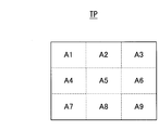
- FIG. FIG. 6 is a diagram showing segmented regions A1 to A9 on the contact sensor surface of the touch sensor panel TP in the contact sensor integrated EL panel 23.
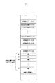
- 3 is a diagram showing an outline of the contents stored in a memory 11.
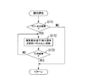
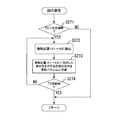
- FIG. It is a flowchart which shows an example of a light control toning subroutine. It is a flowchart which shows another example of the light control toning subroutine.
- the moving body lighting device is based on the contact signal sent from the touch sensor provided on the lighting panel, and the contact mode with respect to the touch sensor is intermittently contacted twice or more within a predetermined period. It is determined whether or not the predetermined intermittent contact is made, and when it is determined that the contact mode is the intermittent contact as described above, the lighting panel is turned on and off. Thereby, it becomes possible to prevent erroneous control of the lighting panel when the fingertip comes into contact with the surface of the lighting panel unintentionally.
- the contact mode is the predetermined first mode
- the lighting panel that has been contacted is turned on, and then the first mode of contact is made to the contact sensor of the lighting panel. Turns off the lighting panel.
- any one of the plurality of lighting panels is intermittently contacted as described above, and the contact mode is a predetermined second mode different from the first mode, all Turn off all the lighting panels at once. Thereby, when all the lighting panels in the lighting state are turned off, it is possible to turn off all the lighting panels all at once without performing an individual turning-off operation on each lighting panel.
- the intermittent contact is a third mode different from the first mode and the second mode, each of the lighting panels designated in advance to be the target of simultaneous lighting is turned on all at once.
- the intermittent contact is a predetermined fourth aspect different from the first aspect, the second aspect, and the third aspect, the light emission color or light emission luminance of the lighting panel is changed.
- FIG. 1 is a block diagram showing a configuration of a moving body illumination device according to the present invention.
- each of the lighting panels 2 1 to 2 n (n is an integer greater than or equal to 2) is, for example, as shown in a broken line in FIG. As shown by the surface of each tension and the broken line in FIG.
- the lighting panels 2 1 to 2 n are connected to the controller 1 via the control bus BUS. Furthermore, the controller 1, the memory 11 via the control bus BUS, the operation unit 12, a timer 13 1 ⁇ 13 n corresponding to the illumination panel 2 1 ⁇ 2 n, respectively, and the illuminance sensor 14 is connected.
- Each of the lighting panels 2 1 to 2 n has the same internal configuration.
- the lighting on / off switch 21 of each lighting panel 2 is turned on when a lighting command signal is supplied from the controller 1 via the control bus BUS, and supplies a power supply voltage VL to an EL (Electroluminescence) panel driver 22.
- the turn-off command signal is supplied from the controller 1 via the control bus BUS
- the turn-on / off switch 21 is turned off and stops supplying the power supply voltage VL to the EL panel driver 22.
- the lighting / extinguishing switch switching command signal is supplied from the controller 1 via the control bus BUS, the lighting / extinguishing switch 21 reverses the on / off state until just before that.
- the on / off switch 21 is switched to the off state, and the supply of the power supply voltage VL to the EL panel driver 22 is stopped.
- the on / off switch switching command signal is supplied in the off state, the on / off switch 21 is switched on and supplies the power supply voltage VL to the EL panel driver 22.
- the EL panel driver 22 performs various operations based on the power supply voltage VL according to various illumination control signals (described later) supplied from the controller 1 via the control bus BUS only while the power supply voltage VL is supplied from the lighting / extinguishing switch 21.
- a light emission driving voltage is generated and supplied to the contact sensor integrated EL panel 23.
- FIG. 3 is a perspective view showing a schematic structure of the contact sensor integrated EL panel 23.
- the contact sensor integrated EL panel 23 is configured by bonding a transparent touch sensor panel TP to the light emitting surface side of the organic EL light emitting panel ELP.
- the organic EL light-emitting panel ELP as a planar EL light-emitting element is lit with light emission luminance and light emission color corresponding to the light emission drive voltage only while the light emission drive voltage is supplied from the EL panel driver 22, and the light is emitted. Release to the outside through the touch sensor panel TP. The organic EL light-emitting panel ELP is turned off when this light emission driving voltage is not supplied.
- the touch sensor panel TP has a contact sensor surface divided into a plurality of regions A1 to A9.
- the touch sensor panel TP is in contact with the position where the contact is made, that is, any region A among the regions A1 to A9 for a period during which the contact continues.
- a contact detection signal TC indicating the contact position information indicating whether or not it has been made and a lighting panel identification number is generated and supplied to the controller 1 via the control bus BUS.
- the illumination panel identification number is a unique number assigned individually to each of the illumination panels 2 1 to 2 n .
- each of the illumination panels 2 1 to 2 n is turned on in response to the lighting command signal supplied from the controller 1 and is turned off in response to the turn-off command signal. Further, when a lighting / extinguishing switch switching command signal is supplied from the controller 1, the lighting / extinguishing state until just before that is reversed. Further, each of the lighting panels 2 1 to 2 n generates a contact detection signal TC every time contact is made with the touch sensor panel TP, and sends this to the controller 1.
- the controller 1 controls lighting, extinction, luminance, and emission color of each of the lighting panels 2 1 to 2 n by executing the following lighting control.
- FIG. 5 is a flowchart showing the main flow of such illumination control.
- the controller 1 executes a lighting dimming toning subroutine for controlling lighting, extinguishing, dimming, and toning for the lighting panels 2 1 to 2 n (step S1).
- the controller 1 executes an illuminance restriction subroutine for restricting illuminance on the illumination panels 2 1 to 2 n (step S2).
- the controller 1 executes an illumination lock mode subroutine for locking the current state of the illumination panels 2 1 to 2 n (step S3).
- step S3 the controller 1 returns to step S1 and repeatedly executes the control of steps S1 to S3.
- FIG. 6 is a flowchart showing the lighting dimming toning subroutine executed in step S1.
- step S11 the controller 1 determines whether or not the contact detection signal TC is supplied from any one of the lighting panels 2 1 to 2 n (step S11).
- step S11 when it is determined that the contact detection signal TC is supplied, the controller 1 performs the following contact mode determination (step S12). That is, by this contact mode determination, the controller 1 counts the number of contact detection signals TC that are intermittently supplied within a predetermined period, and when the number is 2 times, [double-click], 3 times If it is, [triple click], if it is four times, it is determined that [quadro click] operation has been performed. Then, contact mode data TDT indicating the determination result is stored in the memory 11 as shown in FIG.
- the vehicle occupant makes the fingertip contact with the touch sensor panel TP of the illumination panel 2 intermittently only twice within a predetermined period [double click], and intermittently only three times. It is determined in which contact mode the [triple click] that is contacted with [4] and [quadroclick] that is intermittently contacted only four times.
- the controller 1 determines whether or not the contact mode data TDT stored in the memory 11 indicates [double click] (step S13). If it is determined in step S13 that the contact mode data TDT indicates [double click], the controller 1 uses the automatic turn-off flags F 1 to F n stored in the memory 11 as shown in FIG. above-mentioned contact detection signal TC sends a lighting panel 2 (hereinafter, the lighting panel 2 K hereinafter) was carried out as to whether or not a logic level 1 indicating that the auto off flag F K corresponding is in auto oFF Is determined (step S14).
- the lighting panel 2 K hereinafter
- step S14 the automatic off flag F K is determined to be a logic level zero
- the controller 1 sends the On Off switch switching command signal to the lighting panel 2 K (step S15).
- on off switch 21 of the lighting panel 2 K inverts the ON-OFF state until immediately before. That is, when the on / off switch switching command signal is supplied in the on state, the on / off switch 21 is switched to the off state, and the supply of the power supply voltage VL to the EL panel driver 22 is stopped. Thus, a lighting panel 2 K transitions to off state.
- the on / off switch switching command signal is supplied when the on / off switch 21 is in the off state
- the on / off switch 21 is switched on and supplies the power supply voltage VL to the EL panel driver 22.
- a lighting panel 2 K transitions to the lighting state.
- step S15 the lighting panel 2 K, the transition to the lighting state when there Off state until immediately before, if there are lit transitions to off state.
- step S16 determines whether or not the lighting panel 2K is in a lighting state.
- step S16 if the lighting panel 2 K is determined to be lit, the controller 1 will be described later proceeds to execution of Shiki dimming toning subroutine (step S17).
- step S17 the controller 1, of the timer 13 1 ⁇ 13 n respectively, to start time counting of the timer 13 K corresponding to the illumination panel 2 K (step S18).
- step S18 or when the contact detection signal TC is determined to not supplied at step S11, then the controller 1, or the counted time of the timer 13 K exceeds a predetermined auto OFF period TQ It is determined whether or not (step S19).
- step S19 if the time measured by the timer 13 K is determined not to exceed the auto-off period TQ, the controller 1 may then either counted time of the timer 13 K exceeds the auto off start time T ST It is determined whether or not (step S20).
- step S20 if the time measured by the timer 13 K is determined to have exceeded the auto off start time T ST, the controller 1, the emission luminance gradually lighting panel 2 K over a period (TQ-T ST) is fed into an illumination panel 2 K auto off command signal to cause lead to off state is lowered (step S21).
- EL panel driver 22 of the lighting panel 2 K is the light emission drive voltage leading to 0 volts gradually the voltage value over a predetermined period is reduced, the organic EL light emitting panel ELP Supply.
- the controller 1 stores the auto off flag F K logic level 1 indicating that the illumination panel 2 K is being automatically extinguished the memory 11 (step S22).
- step S14 If it is determined in step S14 that the automatic turn-off flag FK is at logic level 1, that is, if [double-click] is performed on the lighting panel 2 that is turned off automatically, the controller 1 An automatic turn-off stop command signal is sent to each of the lighting panels 2 in the lighting state among the lighting panels 2 1 to 2 n (step S23).
- step S23 the EL panel driver 22 of the lighting panel 2 in the lit state stops the operation of reducing the light emission drive voltage to be supplied to the organic EL light emitting panel ELP.
- step S24 After execution of step S23, the controller 1 sends a maximum luminance emission command signal to each of the lighting panels 2 in the lighting state (step S24).
- step S24 the EL panel driver 22 of the lighting panel 2 in the lit state fixes and supplies the maximum light emission driving voltage for causing the organic EL light emitting panel ELP to emit light with the maximum luminance.
- step S24 the controller 1 resets the time measured by the timers 13 1 to 13 n of the lighting panel 2 in the lighting state to the initial value and restarts the time counting operation (step S25).
- the controller 1 causes the time measured by the timer 13 K terminate the counting operation returns to the initial value (step S26).
- the controller 1 stores the auto off flag F K logic level 0 indicating that the lighting panel 2 K is not in auto off in the memory 11 (step S27).
- step S13 determines whether or not the contact mode data TDT indicates [triple click] (step S28). ). If it is determined in step S28 that the contact mode data TDT indicates [triple click], the controller 1 sends out a turn-off command signal to all the lighting panels 2 1 to 2 n (step S29). By executing step S29, all the lighting panels 2 1 to 2 n are turned off, and the supply of the power supply voltage VL to the EL panel driver 22 is stopped. Therefore, all the lighting panels 2 1 to 2 n are turned off.
- the controller 1 returns the time measured by all the timers 13 1 to 13 K to the initial values, and ends all the time measuring operations (step S30).
- the controller 1 stores in the memory 11 the automatic turn-off flags F 1 to F K of logic level 0 indicating that all the lighting panels 2 are not turned off automatically (step S31).
- step S28 determines whether or not the contact mode data TDT does not indicate [triple click] (step S32). ). If it is determined in step S32 that the contact mode data TDT indicates [quadro click], the controller 1 performs illumination within the lighting designation data LG 1 to LG n stored in the memory 11 as shown in FIG. It is determined whether or not the lighting designation data LG K corresponding to the panel 2 K indicates that lighting is designated (step S33). Each of the lighting designation data LG 1 to LG n designates the lighting panel 2 to be turned on at the same time in accordance with [Quadro Click] in each of the lighting panels 2 1 to 2 n. Can be set arbitrarily.
- step S33 if the lighting specified data LG K is determined to indicate that the specified lighting, controller 1 sends a lighting command signal to the lighting panel 2 K (step S34).
- step S34 on off switch 21 of the lighting panel 2 K is turned on, supplies a power supply voltage VL to the EL panel driver 22. Thereby, the illumination panel 2K lights up.
- step S34 the controller 1 proceeds to execution of step S18.
- step S32 If it is determined in step S32 that the contact mode data TDT does not indicate [quadro click], that is, it is determined that none of [double click], [triple click], or [quadro click] has been performed. If so, the controller 1 proceeds to execution of step S19. Further, in step S33, if the lighting specified data LG K is determined to indicate that it has not been specified lit, the controller 1 proceeds to the execution of step S19.
- the first contact sensor surface of the vehicle occupant illumination panel 2 1 ⁇ 2 n [triple-click] Then, all of the lighting panel 2 1 ⁇ 2 n on the on state is turned off (S28, S29 ). Therefore, when all the lighting panels 2 in the lighting state are turned off, the lighting installed in the vicinity of the vehicle occupant without individually [double-clicking] each lighting panel 2 in the lighting state. It is possible to turn off all the lighting panels 2 all at once by simply [triple clicking] one panel 2.
- each of the lighting panel 2 that had previously specified within the lighting panel 2 1 ⁇ 2 n are turned on collectively (S32 to S34). Accordingly, for example, when searching for a fallen object that has fallen on the floor in the room, the user can simply click [quadro click] the contact sensor surface of the lighting panel 2 installed on the dashboard. As shown, the two lighting panels 2 respectively installed on the driver side door and the passenger side door can be turned on simultaneously.
- each of the lighting panels 2 1 to 2 n is automatically turned off when a preset automatic turn-off period TQ elapses after being turned on (S18 to S21). This makes it possible to prevent forgetting to turn off.
- the lighting panel 2 is turned off, the light emission luminance is gradually reduced instead of turning off the light instantaneously (S21).
- the touch sensor surface of the lighting panel 2 is [double-clicked] during the brightness reduction period (while the automatic turn-off flag F is at the logic level 1), the normal lighting state, that is, the highest brightness is obtained again. (S14, S23 to S25). Therefore, since the brightness is gradually reduced, it can be seen that the vehicle occupant is automatically turned off.
- the automatic extinguishing period TQ can be set to a large value (for example, infinite) so that the automatic extinguishing function is substantially disabled.
- the light emission luminance adjustment and the light emission color adjustment are performed by the contact operation on the contact sensor surface of the lighting panel 2 having the light adjustment function and the color adjustment function by the light adjustment color adjustment processing in step S17 illustrated in FIG. .
- FIG. 8 is a flowchart showing an example of a dimming toning subroutine that performs such dimming and toning processing.
- the controller 1 determines whether or not the contact detection signal TC corresponding to the second contact with the contact sensor surface in [double click] is continuously supplied over a predetermined period. (Step S171).
- the contact detection signal TC is supplied continuously for more than a predetermined time period, i.e., when the contact sensor surface of the lighting panel 2 K is determined to have been pressed long, the controller 1, the light emission luminance and supplies to the lighting panel 2 K brightness increase command signal or luminance reduction instruction signal to be higher or lower by a predetermined luminance component (step S172).
- step S172 the controller 1 determines whether or not the contact detection signal TC is no longer supplied (step S173). In step S173, when the contact detection signal TC is determined to continue to be supplied, that is, when the long press to the contact sensor surface of the lighting panel 2 K is determined to be continued, the controller 1, the step S172 The operation as described above is repeatedly executed.
- the increase in luminance and the decrease in luminance in step S172 are performed, for example, by repeating the following processes 1 to 4.
- Process 1 The brightness is gradually increased until the maximum brightness is reached.
- Process 2 When the maximum luminance is reached, the luminance change direction is set to minus (decrease in luminance).
- Process 3 The luminance is gradually decreased until the minimum luminance is reached.
- Process 4 When the minimum luminance is reached, the luminance change is set to plus (luminance increase).
- step S173 when it is determined in step S173 that the contact detection signal TC is no longer supplied, or in step S171, it is determined that the contact detection signal TC is not continuously supplied over a predetermined period. Then, the controller 1 exits from the dimming toning subroutine and returns to the execution of step S18 shown in FIG.
- the illumination panel The 2K emission luminance gradually increases or decreases.
- the lighting panel 2 K emits light while maintaining the light emission luminance when the fingertip is separated from the contact sensor surface.
- N is a natural number of 2 or more
- the light emission luminance may be changed as described above. At this time, after the light emission luminance reaches the maximum luminance, when the contact operation to the contact sensor surface for N times is performed again, the lighting panel 2 is turned off.
- step S172 the controller 1 sets the emission color to “white”, “red”, “orange”, “yellow”, “green”, “blue”, “indigo”, “purple”, “white”. supplying a light emission color change signal to be changed in step opponent by cyclically as in the lighting panel 2 K.
- the emission color of the lighting panel 2 K is "white”, “red”, “orange”, “yellow” , “Green”, “Blue”, “Indigo”, “Purple”.
- the lighting panel 2 K continues to emit light with a state where long press against the contact sensor surface was maintained emission color of the time of completion. Thereby, it becomes possible to select a favorite luminescent color by an easy operation.
- N is a natural number of 2 or more
- the light emission color may be changed as described above.
- a light adjustment toning subroutine as shown in FIG. 9 may be executed instead of the light adjustment toning subroutine shown in FIG.
- the controller 1 determines whether or not the contact detection signal TC corresponding to the second contact with the contact sensor surface in [double click] is continuously supplied over a predetermined period. (Step S271). In step S271, when it is determined that the contact detection signal TC is continuously supplied for a predetermined period or longer, that is, it is determined that a long press has been performed, the controller 1 determines the contact position based on the contact detection signal TC. Is one of the areas A1 to A9 on the contact sensor surface as shown in FIG. 4 (step S272).
- the controller 1 makes contact positions (areas A1 to A9) indicated by the contact detection signal TC according to the contact position light emission color correspondence map stored in the contact position light emission color correspondence map area of the memory 11 as shown in FIG. It obtains light emission color corresponding to), and supplies the emission color designation signal for designating the emission color to the lighting panel 2 K (step S273).
- EL panel driver 22 of the lighting panel 2 K supplies the light emission drive voltage to be lit in the specified emission color in the light-emitting color designation signal to the organic EL light emitting panel ELP. Accordingly, at this time, the illumination panel 2K emits light in the light emission color designated by the above-described light emission color designation signal.
- each emission color is shown in each of the areas A1 to A9 on the contact sensor surface as shown in FIG. 4 in the form of a chromaticity diagram defined by CIE (Commission Internationale de l'Eclairage) It is associated.
- CIE Commission Internationale de l'Eclairage
- step S274 If it is determined in step S274 that the contact detection signal TC is no longer supplied, or if it is determined in step S271 that the contact detection signal TC is not continuously supplied over a predetermined period, the controller 1 Leaves the dimming toning subroutine and returns to the execution of step S18 shown in FIG.
- the lighting panel 2 K continues light emission while maintaining an emission color corresponding to the contact position when the fingertip is separated from the contact sensor surface.
- the contact mode of the illumination panel with respect to the touch sensor is a predetermined intermittent contact in which the contact is intermittently performed twice or more within a predetermined period. It is determined whether or not (2 to 4 clicks), and the lighting panel is turned on, turned off, dimmed, and toned only when it is determined that the contact is intermittent. Thereby, even if a passenger's finger contacts the surface of the lighting panel 2 by mistake, the contact is not accepted. Therefore, only the operation intended by the vehicle occupant can be accepted, and the lighting panel 2 can be turned on, turned off, dimmed, and toned.
- step S2 After executing the lighting dimming toning control, the controller 1 executes an illuminance restriction subroutine (step S2). At this time, an arbitrary upper limit of illuminance is input in advance by the operation unit 12. Thereby, the illuminance upper limit value YL indicating the input illuminance upper limit value is stored in the memory 11 as shown in FIG.
- FIG. 10 is a flowchart showing an example of the illuminance restriction subroutine.
- the controller 1 determines whether or not the room illuminance detected by the illuminance sensor 14 is larger than the above-described illuminance upper limit value YL (step S371). If it is determined in step S371 that the room illuminance is greater than the illuminance upper limit value YL, the controller 1 determines that the vehicle is on the basis of a vehicle parking signal or a side brake signal supplied from a vehicle travel control system (not shown). It is determined whether the vehicle is traveling (step S372). If it is determined in step S372 that the vehicle is running, the controller 1 sets the time counted by the timer 13 corresponding to the illumination panel 2 among the currently illuminated lighting panels 2n.
- step S373 A turn-off command signal is sent to the large lighting panel 2 (step S373).
- step S373 By executing step S373, one illumination panel 2 is turned off, so that the room illuminance decreases.
- the controller 1 returns to the execution of step S371 described above and repeatedly executes the operation as described above. During this time, if it is determined in step S371 that the room illuminance is smaller than the illuminance upper limit YL, or if it is determined in step S372 that the vehicle is not running, that is, the vehicle is stopped, the controller 1 Exiting the restriction subroutine, the process proceeds to execution of step S3 shown in FIG.
- step S373 the lighting start time is turned off one by one in the order of the old lighting panel 2 until the room illuminance becomes smaller than the illuminance upper limit YL.
- step S373 the lighting panel 2 is turned off, but instead, the light emission luminance of each lighting panel 2 in the lit state may be lowered all at once by a predetermined luminance.
- the number of lighting panels 2 that are automatically turned on is automatically set so that the indoor illuminance during vehicle traveling does not become higher than the predetermined illuminance upper limit value.
- Illuminance restriction processing is performed to reduce or reduce the luminance of all the lighting panels 2 that are lit. Note that if the illuminance data when each of the lighting panels 2 1 to 2 n is turned on is recorded in the memory by measuring in advance, the illuminance by the plurality of lighting panels that are turned on can be obtained by calculation.
- the illuminance sensor 14 may not be provided.
- the controller 1 After execution of the illuminance restriction, the controller 1 locks the lighting / extinguishing state of each lighting panel 2 at the present time, that is, the lighting lock mode subroutine for invalidating the contact operation of each lighting panel 2 to the touch sensor panel TP. Is executed (step S3).
- FIG. 11 is a flowchart showing an example of such an illumination lock mode subroutine.
- the controller 1 first determines whether or not the contact detection signal TC is supplied from any one of the lighting panels 2 1 to 2 n (step S471). When it is determined in step S471 that the contact detection signal TC is supplied, the controller 1 performs the following contact mode determination (step S472). By such contact mode determination, the controller 1 counts the number of contact detection signals TC supplied within a predetermined period. When the number is 5 times, [5 clicks], when the number is 6, Determines that [6 click] has been made, and stores the contact mode data TDT indicating the determination result in the memory 11 as shown in FIG.
- the vehicle occupant touches the touch sensor panel TP of any one of the lighting panels 2 1 to 2 n with the fingertips only five times within a predetermined period [ 5 clicks] or [6 clicks] in which contact is made intermittently 6 times is determined in which contact mode is used.
- the vehicle occupant turns on the illumination lock mode for locking the lighting / extinguishing state of each lighting panel 2, one of the touch panels TP of the lighting panels 2 1 to 2 n is touched. [5 click] operation as described above.
- the vehicle occupant performs the [6 click] operation as described above.
- the controller 1 determines whether or not the contact mode data TDT stored in the memory 11 indicates [5 clicks] (step S473).
- step S473 When it is determined in step S473 that the contact mode data TDT indicates [5 clicks], the controller 1 masks reception of the above [double click], [triple click], and [quadro click], that is, a lighting / extinguishing operation. The reception is masked for the operation of the contact mode that bears (step S474). By executing step S474, the controller 1 enters a state where it is determined that these operations have not been performed even if [double click], [triple click], or [quadro click] is performed by the vehicle occupant. .
- step S473 when it is determined in step S473 that the contact mode data TDT does not indicate [5 clicks], the controller 1 determines whether or not the contact mode data TDT indicates [6 clicks] (step S475). . If it is determined in step S475 that the contact mode data TDT indicates [6 clicks], the controller 1 cancels the reception mask state of the above [double click], [triple click], and [quadro click] ( Step S476). After execution of step S476 or S474, or when it is determined in step S475 that the contact mode data TDT does not indicate [6 clicks], or when it is determined in S471 that the contact detection signal TC is not supplied. Then, the controller 1 exits from the illumination lock mode subroutine and proceeds to execution of step S1 shown in FIG.
- the vehicle occupant can select [1] the touch sensor panel TP of the illumination panel 2 of each of the illumination panels 2 1 to 2 n [ By clicking [5 clicks], the lighting lock mode is entered in which subsequent [double click], [triple click] and [quadro click] are not accepted.
- the [double-click], [triple-click] and [quadro-click] operations for turning on / off the lighting panel 2 become invalid, so that the unintended contact with the lighting panel 2 or mischief of the child, etc. Can be prevented.
- the lighting panel 2 to be locked is set in advance by the operation unit 12, and in the lighting lock mode, only the lighting panel 2 set as the locking target is [double-click], [triple] You may make it the reception prohibition state of [click] and [quadro click].
- the lighting panel 2 is turned on / off by the touch sensor panel TP, but a push switch or a toggle switch may be used instead of the touch sensor panel TP. This makes it possible to turn on / off the illumination panel 2 without performing a delicate operation such as [double click].
- the inversion of a lighting / light-off state is a 1st contact mode [double click]
- All the lighting panel simultaneous turn-off is a 2nd contact mode [triple click]
- the lighting panel designated beforehand The simultaneous lighting is executed by [quadro click] that is the third contact mode, and the dimming and toning are performed by [long press] that is the fourth contact mode.
- the first to third contact modes are not limited to [Double click], [Triple click], and [Quadro click] as described above.
- the first contact mode is an operation in which the fingertip is intermittently contacted N times (N is a natural number of 2 or more) within a predetermined period
- the second contact mode is an operation in which the fingertip is intermittently contacted M times (M ⁇ N).
- N and L times L ⁇ M, L ⁇ N) may be the third contact mode.
- an operation in which the fingertip contacts intermittently S times (S ⁇ M, S ⁇ N, S ⁇ L) within a predetermined period may be set as the fourth contact mode.
- each of the first to fourth contact modes has different contact patterns by combining a [click] operation in which the fingertip is intermittently contacted a plurality of times within a predetermined period and a [long press] operation. It may be adopted.
- a [click] operation in which the fingertip is intermittently contacted a plurality of times within a predetermined period
- a [long press] operation it may be adopted.
- the specific contact pattern in addition to a case in which each operation is sequentially performed in the order of [click] operation and [long press] operation (or vice versa), [click] operation, [long press] operation, [ Three or more operations may be successively performed in the order of “click” operation, or “long press” operation, “click” operation, and “long press” operation.
- Controller 2 1 to 2 n Lighting panel 21 ON / OFF switch ELP Organic EL light emitting panel TP Touch sensor panel
Landscapes
- Engineering & Computer Science (AREA)
- Mechanical Engineering (AREA)
- Arrangements Of Lighting Devices For Vehicle Interiors, Mounting And Supporting Thereof, Circuits Therefore (AREA)
- Circuit Arrangement For Electric Light Sources In General (AREA)
Abstract
照明パネルに設けられているタッチセンサから送出された接触信号に基づいてこのタッチセンサに対する接触態様が所定期間内において2回以上の接触が断続的に為される所定の断続接触であるか否かを判定し、この接触態様が上記の如き断続接触であると判定された場合に照明パネルの点灯及び消灯制御を行う。
Description
本発明は、移動体、特に移動体室内用の移動体用照明装置に関する。
現在、車両の室内灯として、有機エレクトロルミネセンス発光パネル(以下、EL発光パネルと称する)をファブリックと基材(又はフォーム層)との間に設置し、このEL発光パネルから発せられた光をファブリック越しに室内に差し向けるように構築されたものが提案されている(例えば、特許文献1参照)。この際、照明パネルとしてのEL発光パネルは、白熱ランプとは異なり放熱を考慮する必要が無いので、例えば車室内のヘッドライナー、ドアパネル、乗物座席(シート)、リヤデッキ、サンバイザ、トランクパネル等に設置することが可能である。
また、このEL発光パネルに、点灯・消灯を切り替える為のタッチセンサを一体化したものが提案されている(例えば、特許文献2参照)。このタッチセンサ一体型のEL発光パネルを、車両の室内灯として必要箇所に夫々設置すれば、車両の搭乗者がEL発光パネルの表面に触れることにより、そのEL発光パネルの点灯・消灯を行うことが可能となる。
しかしながら、車両室内の如き狭い空間では、意図せずにEL発光パネルの表面に触れてしまうことがある為、本来、点灯状態に維持させておくべきEL発光パネルを消灯させてしまったり、点灯させる必要の無いEL発光パネルを点灯させてしまう等の誤った制御が為される虞があった。
本発明は上記した点に鑑みて為されたものであり、意図した操作のみを受け付けて照明パネルを制御することが可能な移動体用照明装置を提供することを目的とする。
本発明による移動体用照明装置は、移動体の室内に設置する移動体用照明装置であって、照明パネルと、前記照明パネルに設けられているタッチセンサと、前記タッチセンサから送出された接触信号に基づいて前記タッチセンサに対する接触態様が所定期間内において2回以上の接触が断続的に為される所定の断続接触であるか否かを判定する接触態様判定部と、前記接触態様が前記断続接触であると判定された場合に前記照明パネルの点灯及び消灯制御を行う点灯消灯制御部と、を有する。
本発明に係る移動体用照明装置は、照明パネルに設けられているタッチセンサから送出された接触信号に基づいてこのタッチセンサに対する接触態様が所定期間内において2回以上の接触が断続的に為される所定の断続接触であるか否かを判定し、この接触態様が上記の如き断続接触であると判定された場合に照明パネルの点灯及び消灯制御を行う。これにより、意図せずに照明パネルの表面に指先が接触してしまった場合の誤った照明パネルの制御を防止することが可能となる。この際、接触態様が所定の第1態様である場合にはこの接触の為された照明パネルを点灯させ、その後、この照明パネルの接触センサに対して第1態様の接触が為された場合には、この照明パネルを消灯させる。また、複数の照明パネル各々の内のいずれか1の照明パネルに対して上記した如き断続接触が為され、その接触態様が第1態様とは異なる所定の第2態様である場合には、全ての照明パネルを一斉に消灯させる。これにより、点灯状態にある照明パネルを全て消灯させる際に、各照明パネルに対して個別に消灯操作を行わずとも、全ての照明パネルを一斉に消灯させることが可能となる。また、その断続接触が第1態様及び第2態様とは異なる第3態様である場合には、予め一斉点灯の対象となるべく指定された照明パネルの各々を一斉に点灯する。また、その断続接触が第1態様、第2態様及び第3態様とは異なる所定の第4態様である場合には、照明パネルの発光色又は発光輝度を変更する。
図1は、本発明に係る移動体用照明装置の構成を示すブロック図である。
尚、移動体としては、車両、電車、航空機、船舶、潜水艦、又は宇宙船等が上げられるが、本実施例では、車両の室内に搭載された場合を一例にとって説明する。
図1において、照明パネル21~2n(nは2以上の整数)の各々は、例えば図2(a)の破線に示す如く、車両室内の運転席のフロントパネル、コンソールボックス及びドアの内張各々の表面、並びに、図2(b)の破線に示す如く車両内の天井面に夫々設置される。照明パネル21~2nは夫々制御バスBUSを介してコントローラ1に接続されている。更に、コントローラ1には、制御バスBUSを介してメモリ11、操作部12、照明パネル21~2n各々に対応したタイマ131~13n、及び照度センサ14が接続されている。
照明パネル21~2nの各々は互いに同一の内部構成を有する。
各照明パネル2の点灯消灯スイッチ21は、制御バスBUSを介してコントローラ1から点灯指令信号が供給された場合にはオン状態となり、電源電圧VLをEL(Electro luminescence)パネルドライバ22に供給する。また、点灯消灯スイッチ21は、制御バスBUSを介してコントローラ1から消灯指令信号が供給された場合にはオフ状態となり、ELパネルドライバ22への電源電圧VLの供給を停止する。また、点灯消灯スイッチ21は、制御バスBUSを介してコントローラ1から点灯消灯スイッチ切換指令信号が供給された場合には、その直前までのオン・オフ状態を反転させる。すなわち、オン状態にある際に、点灯消灯スイッチ切換指令信号が供給された場合には、点灯消灯スイッチ21はオフ状態に切り替わり、ELパネルドライバ22への電源電圧VLの供給を停止する。一方、オフ状態にある際に点灯消灯スイッチ切換指令信号が供給された場合には、点灯消灯スイッチ21はオン状態に切り替わり、電源電圧VLをELパネルドライバ22に供給する。
ELパネルドライバ22は、点灯消灯スイッチ21から電源電圧VLが供給されている間だけ、制御バスBUSを介してコントローラ1から供給された各種照明制御信号(後述する)に従って、電源電圧VLに基づき各種発光駆動電圧を生成し、接触センサ一体型ELパネル23に供給する。
図3は、接触センサ一体型ELパネル23の概略構造を示す斜視図である。
図3に示すように、接触センサ一体型ELパネル23は、有機EL発光パネルELPの発光面側に透明なタッチセンサパネルTPを貼合して構成されたものである。
平面型のEL発光素子としての有機EL発光パネルELPは、ELパネルドライバ22から発光駆動電圧が供給されている間だけ、その発光駆動電圧に応じた発光輝度及び発光色で点灯し、その光をタッチセンサパネルTPを介して外部に放出する。尚、有機EL発光パネルELPは、この発光駆動電圧が供給されていない場合は消灯状態となる。
タッチセンサパネルTPは、図4に示すように、その接触センサ面が複数の領域A1~A9に区分けされている。タッチセンサパネルTPは、接触センサ面に対して接触が為されるとその接触が継続する期間中に亘り、接触が為された位置、つまり領域A1~A9の内のいずれの領域Aに接触が為されたかを示す接触位置情報及び照明パネル識別番号を示す接触検知信号TCを生成し、これを制御バスBUSを介してコントローラ1に供給する。尚、照明パネル識別番号は、照明パネル21~2nの各々に個別に割り当てられているユニークな番号である。
上記した如き構成により、照明パネル21~2nの各々は、コントローラ1から供給された点灯指令信号に応じて点灯し、消灯指令信号に応じて消灯する。また、コントローラ1から点灯消灯スイッチ切換指令信号が供給された場合には、その直前までの点灯・消灯状態を反転させる。更に、照明パネル21~2nの各々は、そのタッチセンサパネルTPに対して接触が為される度に接触検知信号TCを生成し、これをコントローラ1に送出する。
コントローラ1は、以下の如き照明制御を実行することにより、照明パネル21~2n各々の点灯、消灯、輝度、発光色を制御する。
図5は、かかる照明制御のメインフローを示すフローチャートである。
図5において、先ず、コントローラ1は、照明パネル21~2nに対して点灯、消灯、調光及び調色制御を司る点灯調光調色サブルーチンを実行する(ステップS1)。次に、コントローラ1は、照明パネル21~2nに対して照度制限を施す為の照度制限サブルーチンを実行する(ステップS2)。次に、コントローラ1は、照明パネル21~2nの現時点での状態をロックする為の照明ロックモードサブルーチンを実行する(ステップS3)。かかるステップS3の実行後、コントローラ1は、上記ステップS1に戻ってステップS1~S3の制御を繰り返し実行する。
図6は、ステップS1において実施される点灯調光調色サブルーチンを示すフローチャートである。
図6において、先ず、コントローラ1は、照明パネル21~2nの内のいずれか1から接触検知信号TCが供給されたか否かの判定を行う(ステップS11)。かかるステップS11において、接触検知信号TCが供給されたと判定された場合、コントローラ1は、以下の如き接触態様判定を実行する(ステップS12)。すなわち、この接触態様判定により、コントローラ1は、所定期間内において断続的に供給された接触検知信号TCの数をカウントし、その数が2回であった場合には[ダブルクリック]、3回であった場合には[トリプルクリック]、4回であった場合には[クワドロクリック]操作が為されたと判定する。そして、その判定結果を示す接触態様データTDTを図7に示す如くメモリ11に記憶させる。
すなわち、かかる接触態様判定により、照明パネル2のタッチセンサパネルTPに対して、車両搭乗者が、所定期間内にその指先を2回だけ断続的に接触させる[ダブルクリック]、3回だけ断続的に接触させる[トリプルクリック]、4回だけ断続的に接触させる[クワドロクリック]の内のいずれの接触態様で接触したのかを判定する。
この接触態様判定の実行後、コントローラ1は、メモリ11に記憶された接触態様データTDTが[ダブルクリック]を示すか否かを判定する(ステップS13)。ステップS13において、接触態様データTDTが[ダブルクリック]を示すと判定された場合、コントローラ1は、図7に示す如くメモリ11に記憶されている自動消灯中フラグF1~Fnの内で、上記した接触検知信号TCの送出を行った照明パネル2(以降、照明パネル2Kと称する)に対応した自動消灯中フラグFKが自動消灯中であることを示す論理レベル1であるか否かを判定する(ステップS14)。かかるステップS14において、自動消灯中フラグFKが論理レベル0であると判定されると、コントローラ1は、照明パネル2Kに対して点灯消灯スイッチ切換指令信号を送出する(ステップS15)。かかる点灯消灯スイッチ切換指令信号に応じて、この照明パネル2Kの点灯消灯スイッチ21は、その直前までのオン・オフ状態を反転させる。すなわち、オン状態にある際に点灯消灯スイッチ切換指令信号が供給された場合には、点灯消灯スイッチ21はオフ状態に切り替わり、ELパネルドライバ22への電源電圧VLの供給を停止する。これにより、照明パネル2Kは消灯状態に遷移する。一方、点灯消灯スイッチ21がオフ状態にある際に点灯消灯スイッチ切換指令信号が供給された場合には、この点灯消灯スイッチ21はオン状態に切り替わり、電源電圧VLをELパネルドライバ22に供給する。これにより、照明パネル2Kは点灯状態に遷移する。
すなわち、ステップS15の実行により、照明パネル2Kは、その直前まで消灯状態にあった場合には点灯状態に遷移し、点灯状態にあった場合には消灯状態に遷移する。
次に、コントローラ1は、この照明パネル2Kが点灯状態にあるか否かを判定する(ステップS16)。かかるステップS16において、照明パネル2Kが点灯状態にあると判定された場合、コントローラ1は、後述するが如き調光調色サブルーチンの実行に移る(ステップS17)。かかるステップS17の実行後、次に、コントローラ1は、タイマ131~13n各々の内で、照明パネル2Kに対応したタイマ13Kの時間計時を開始させる(ステップS18)。ステップS18の実行後、又はステップS11にて接触検知信号TCが供給されていないと判定された場合、次に、コントローラ1は、このタイマ13Kの計時時間が所定の自動消灯期間TQを超えたか否かの判定を行う(ステップS19)。かかるステップS19において、タイマ13Kの計時時間が自動消灯期間TQを超えていないと判定された場合、コントローラ1は、次に、このタイマ13Kの計時時間が自動消灯開始時間TSTを超えたか否かの判定を行う(ステップS20)。かかるステップS20において、タイマ13Kの計時時間が自動消灯開始時間TSTを超えたと判定された場合、コントローラ1は、期間(TQ-TST)を掛けて徐々に照明パネル2Kの発光輝度を低下させて消灯状態に到らせるべき自動消灯指令信号を照明パネル2Kに供給する(ステップS21)。この自動消灯指令信号に応じて、照明パネル2KのELパネルドライバ22は、所定期間を掛けて徐々にその電圧値が低下して0ボルトに到る発光駆動電圧を、有機EL発光パネルELPに供給する。かかるステップS21の実行後、コントローラ1は、照明パネル2Kが自動消灯中であることを示す論理レベル1の自動消灯中フラグFKをメモリ11に記憶させる(ステップS22)。
また、上記ステップS14において自動消灯中フラグFKが論理レベル1であると判定された場合、つまり、自動消灯中の照明パネル2に対して[ダブルクリック]が為された場合、コントローラ1は、照明パネル21~2nの内で点灯状態にある照明パネル2の各々に対して自動消灯停止指令信号を送出する(ステップS23)。かかるステップS23の実行により、点灯状態にある照明パネル2のELパネルドライバ22は、有機EL発光パネルELPに供給すべき発光駆動電圧の低下動作を停止する。ステップS23の実行後、コントローラ1は、点灯状態にある照明パネル2の各々に対して最大輝度発光指令信号を送出する(ステップS24)。かかるステップS24の実行により、点灯状態にある照明パネル2のELパネルドライバ22は、有機EL発光パネルELPを最大輝度で発光させるべき最大の発光駆動電圧を有機EL発光パネルELPに固定供給する。かかるステップS24の実行後、コントローラ1は、点灯状態にある照明パネル2のタイマ131~13nの計時時間を初期値に戻してその時間計時動作を再開する(ステップS25)。尚、上記ステップS19においてタイマ13Kの計時時間が自動消灯期間TQを超えたと判定された場合、つまり照明パネル2が消灯した場合、又は上記ステップS16において照明パネル2Kが点灯状態にはないと判定された場合、コントローラ1は、タイマ13Kの計時時間を初期値に戻しその計時動作を終了させる(ステップS26)。次に、コントローラ1は、照明パネル2Kが自動消灯中ではないことを示す論理レベル0の自動消灯中フラグFKをメモリ11に記憶させる(ステップS27)。
また、上記ステップS13において、接触態様データTDTが[ダブルクリック]を示さないと判定された場合、コントローラ1は、この接触態様データTDTが[トリプルクリック]を示すか否かを判定する(ステップS28)。かかるステップS28において、接触態様データTDTが[トリプルクリック]を示すと判定された場合、コントローラ1は、全ての照明パネル21~2nに対して消灯指令信号を送出する(ステップS29)。かかるステップS29の実行により、全ての照明パネル21~2n各々の点灯消灯スイッチ21はオフ状態となり、ELパネルドライバ22に対する電源電圧VLの供給を停止する。よって、全ての照明パネル21~2nが消灯状態となる。
次に、コントローラ1は、全てのタイマ131~13Kの計時時間を初期値に戻しその計時動作を全て終了させる(ステップS30)。次に、コントローラ1は、全ての照明パネル2が自動消灯中ではないことを示す論理レベル0の自動消灯中フラグF1~FKをメモリ11に記憶させる(ステップS31)。
また、上記ステップS28において、接触態様データTDTが[トリプルクリック]を示さないと判定された場合、コントローラ1は、この接触態様データTDTが[クワドロクリック]を示すか否かを判定する(ステップS32)。かかるステップS32において、接触態様データTDTが[クワドロクリック]を示すと判定された場合、コントローラ1は、図7に示す如くメモリ11に記憶されている点灯指定データLG1~LGnの内で照明パネル2Kに対応した点灯指定データLGKが、点灯指定されていることを示すか否かを判定する(ステップS33)。尚、点灯指定データLG1~LGnの各々は、照明パネル21~2n各々の内で、[クワドロクリック]に応じて同時に点灯させるべき照明パネル2を指定するものであり、操作部12によって任意に設定可能である。例えば、[クワドロクリック]に応じて照明パネル21及び25を同時に点灯させる為には、操作部12によって、照明パネル21に対応した点灯指定データLG1及び照明パネル25に対応した点灯指定データLG5を論理レベル1に設定する。上記ステップS33において、点灯指定データLGKが点灯指定されていることを示すと判定された場合、コントローラ1は、照明パネル2Kに対して点灯指令信号を送出する(ステップS34)。かかるステップS34の実行により、照明パネル2Kの点灯消灯スイッチ21はオン状態となり、電源電圧VLをELパネルドライバ22に供給する。これにより、照明パネル2Kが点灯する。
かかるステップS34の実行後、コントローラ1は、上記ステップS18の実行に移る。
また、上記ステップS32において接触態様データTDTが[クワドロクリック]を示さないと判定された場合、つまり、[ダブルクリック]、[トリプルクリック]、[クワドロクリック]のいずれもが為されていないと判定された場合、コントローラ1は、上記ステップS19の実行に移る。また、上記ステップS33において、点灯指定データLGKが点灯指定されていないことを示すと判定された場合、コントローラ1は、上記ステップS19の実行に移る。
ここで、上記ステップS22、S25、S27又はS31の実行後、或いは上記ステップS20においてタイマ13Kの計時時間が自動消灯開始時間TSTを超えていないと判定された場合、コントローラ1は、図6に示す点灯調光調色サブルーチンを抜けて図5に示すメインフローに戻る。
以上の如く、図6に示される点灯調光調色制御によれば、車両搭乗者が図2(a)又は図2(b)の如く車両内に設置されている複数の照明パネル21~2nの内の1の接触センサ面を[ダブルクリック]すると、その照明パネル2が点灯し、その後、再び[ダブルクリック]すると消灯状態となる(S13~S15)。
又、車両搭乗者が照明パネル21~2nの内の1の接触センサ面を[トリプルクリック]すると、点灯状態にある全ての照明パネル21~2nが消灯状態となる(S28、S29)。よって、点灯状態にある全ての照明パネル2を消灯させる場合には、この点灯状態にある照明パネル2の各々を個別に[ダブルクリック]せずとも、車両搭乗者の身近に設置されている照明パネル2を1つだけ[トリプルクリック]するだけで全ての照明パネル2を一斉に消灯させることが可能となる。
又、車両搭乗者が、照明パネル21~2nの内の1の接触センサ面を[クワドロクリック]すると、照明パネル21~2n各々の内で予め指定したおいた照明パネル2の各々が一括して点灯状態になる(S32~S34)。これにより、例えば室内の床に落下してしまった落下物を探す場合には、ダッシュボードに設置されている照明パネル2の接触センサ面を[クワドロクリック]するだけで、図2(a)に示す如く運転者側のドア及び助手席側のドアに夫々設置されている2つの照明パネル2を同時に点灯させることが可能となる。
また、照明パネル21~2nの各々は、その点灯後、予め設定されている自動消灯期間TQが経過すると自動的に消灯する(S18~S21)。これにより、消し忘れを防止することが可能となる。尚、照明パネル2を消灯するにあたり瞬時に消灯するのではなく、徐々に発光輝度を低下させるようにしている(S21)。この際、輝度の低下期間中(自動消灯中フラグFが論理レベル1である間中)に、その照明パネル2の接触センサ面を[ダブルクリック]すると、再び通常の点灯状態、つまり最高輝度での点灯状態に復帰する(S14、S23~S25)。よって、輝度が徐々に低下することにより、車両の搭乗者は自動消灯していることがわかる為、この間、必要ならば照明パネル2の接触センサ面を[ダブルクリック]することにより、点灯状態に復帰させることが可能となる。なお、自動消灯期間TQを大きな値に設定(例えば無限大)することで、実質的に自動消灯を機能しないようにすることも可能である。
また、図6に示すステップS17による調光調色処理により、調光機能及び調色機能を有する照明パネル2の接触センサ面に対する接触操作により、発光輝度の調整及び発光色の調整が為される。
図8は、かかる調光調色処理を担う調光調色サブルーチンの一例を示すフローチャートである。
図8において、先ず、コントローラ1は、[ダブルクリック]における第2回目の接触センサ面への接触に対応した接触検知信号TCが所定期間以上に亘り継続して供給されているか否かを判定する(ステップS171)。ステップS171において、接触検知信号TCが所定期間以上に亘り継続して供給されている、すなわち、照明パネル2Kの接触センサ面が長押しされていると判定された場合、コントローラ1は、発光輝度を所定輝度分だけ高く又は低くさせるべき輝度増加指令信号又は輝度低下指令信号をこの照明パネル2Kに供給する(ステップS172)。かかる輝度増加指令信号又は輝度低下指令信号に応じて、照明パネル2KのELパネルドライバ22は、有機EL発光パネルELPに供給している発光駆動電圧の電圧値を所定値だけ増加又は低下する。これにより、照明パネル2Kの発光輝度が増加又は低下する。ステップS172の実行後、コントローラ1は、接触検知信号TCが供給されなくなったか否かを判定する(ステップS173)。ステップS173において、接触検知信号TCが引き続き供給されていると判定された場合、つまり照明パネル2Kの接触センサ面に対する長押しが継続していると判定された場合、コントローラ1は、上記ステップS172の実行に戻り、前述した如き動作を繰り返し実行する。ステップS172における輝度増加および輝度低下は、例えば以下の如き処理1~4を繰り返すことによって行われる。
処理1:最大輝度に達するまで輝度を徐々に増加させる。
処理2:最大輝度に達すると輝度の変化方向をマイナス(輝度低下)に設定する。
処理3:最低輝度に達するまで輝度を徐々に低下させる。
処理4:最低輝度に達すると輝度の変化をプラス(輝度増加)に設定する。
処理2:最大輝度に達すると輝度の変化方向をマイナス(輝度低下)に設定する。
処理3:最低輝度に達するまで輝度を徐々に低下させる。
処理4:最低輝度に達すると輝度の変化をプラス(輝度増加)に設定する。
ここで、上記ステップS173において接触検知信号TCの供給が為されなくなったと判定された場合、又は上記ステップS171において接触検知信号TCが所定期間以上に亘り継続して供給されていないと判定された場合、コントローラ1は、この調光調色サブルーチンを抜けて図6に示すステップS18の実行に戻る。
よって、図8に示される調光調色サブルーチンによれば、照明パネル2Kの接触センサ面に指先が継続して接触している、いわゆる長押しが為されている間に亘り、この照明パネル2Kの発光輝度が徐々に増加又は低下する。この際、照明パネル2Kは、その接触センサ面から指先が離れた際の発光輝度を維持した状態で発光する。尚、照明パネル2Kの接触センサ面に対する長押し接触操作に代えて、所定期間あたりN回(Nは2以上の自然数)の断続的な接触センサ面に対する接触操作自体を繰り返し実行することにより、上記した如き発光輝度の変更を行うようにしても良い。この際、発光輝度が最大輝度になった後に、再びN回分の断続的な接触センサ面に対する接触操作が為されたときに、この照明パネル2を消灯状態にする。
尚、上記ステップS172及びS173の繰り返し実行によれば、照明パネル2Kの発光輝度が段階敵に増加又は低下するが、発光色を段階敵に変化させるようにしても良い。例えば、上記ステップS172において、コントローラ1は、発光色を「白」、「赤」、「橙」、「黄」、「緑」、「青」、「藍」、「紫」、「白」の如く巡回させて段階敵に変化させるべき発光色変化信号をこの照明パネル2Kに供給する。これにより、照明パネル2Kの接触センサ面に対して長押しが為されている間に亘り、この照明パネル2Kの発光色が、「白」、「赤」、「橙」、「黄」、「緑」、「青」、「藍」、「紫」の順に変化してゆく。この際、照明パネル2Kは、その接触センサ面に対する長押しが終了した時点の発光色を維持した状態で発光を継続する。これにより、好みの発光色を容易な操作で選択することが可能となる。尚、照明パネル2Kの接触センサ面に対する長押し接触操作に代えて、所定期間あたりN回(Nは2以上の自然数)の断続的な接触センサ面に対する接触操作自体を繰り返し実行することにより、上記した如き発光色の変更を行うようにしても良い。
又、ステップS17での調光調色処理としては、図8に示す調光調色サブルーチンに代えて、図9に示す如き調光調色サブルーチンを実行するようにしても良い。
図9において、先ず、コントローラ1は、[ダブルクリック]における第2回目の接触センサ面への接触に対応した接触検知信号TCが所定期間以上に亘り継続して供給されているか否かを判定する(ステップS271)。ステップS271において、接触検知信号TCが所定期間以上に亘り継続して供給されている、つまり長押しが為されていると判定された場合、コントローラ1は、接触検知信号TCに基づき、その接触位置が図4に示す如き接触センサ面の領域A1~A9のいずれの領域であるのかを検出する(ステップS272)。次に、コントローラ1は、図7に示す如くメモリ11の接触位置発光色対応マップ領域に記憶されている接触位置発光色対応マップに従って、接触検知信号TCにて示される接触位置(領域A1~A9)に対応した発光色を求め、その発光色を指定する発光色指定信号を照明パネル2Kに供給する(ステップS273)。ステップS273の実行により、照明パネル2KのELパネルドライバ22は、かかる発光色指定信号にて指定された発光色で発光させるべき発光駆動電圧を有機EL発光パネルELPに供給する。よって、この際、照明パネル2Kは、上記した発光色指定信号にて指定された発光色で発光する。尚、接触位置発光色対応マップでは、例えばCIE(Commission Internationale de l ’Eclairage)が定めた色度図の形態にて図4に示す如き接触センサ面の領域A1~A9各々に、各発光色が対応付けされている。上記ステップS273の実行後、コントローラ1は、接触検知信号TCが供給されなくなったか否かを判定する(ステップS274)。ステップS274において、接触検知信号TCが引き続き供給されていると判定された場合、つまり長押しが継続していると判定された場合、コントローラ1は、上記ステップS272の実行に戻り、前述した如き動作を繰り返し実行する。上記ステップS274において接触検知信号TCの供給が為されなくなったと判定された場合、又は上記ステップS271において接触検知信号TCが所定期間以上に亘り継続して供給されていないと判定された場合、コントローラ1は、この調光調色サブルーチンを抜けて図6に示すステップS18の実行に戻る。
図9に示される調光調色サブルーチンによれば、照明パネル2Kの接触センサ面に対する長押しが為されている間に亘り、その接触位置に対応した発光色で照明パネル2Kが発光する。この際、照明パネル2Kは、その接触センサ面から指先が離れた際の接触位置に対応した発光色を維持した状態で発光を継続する。
よって、照明パネル2Kの接触センサ面に対する接触位置を移動させることにより発光色を変更することができるので、好みの発光色を容易な操作で選択することが可能となる。
以上の如く、図6に示される点灯調光調色制御(ステップS1)では、照明パネルのタッチセンサに対する接触態様が所定期間内において2回以上の接触が断続的に為される所定の断続接触(2~4クリック)であるか否かを判定し、この断続接触であると判定された場合にだけ照明パネルの点灯、消灯、調光及び調色を行うようにしている。これにより、照明パネル2の表面に誤って搭乗者の指が接触してしまっても、その接触は受け付けられない。よって、車両搭乗者の意図した操作のみを受け付けて照明パネル2を点灯、消灯、調光、調色制御することが可能となる。
かかる点灯調光調色制御の実行後、コントローラ1は、照度制限サブルーチンを実行する(ステップS2)。この際、予め操作部12によって任意の照度上限値を入力しておく。これにより、入力された照度上限値の値を示す照度上限値YLが図7に示す如くメモリ11に記憶される。
図10は、照度制限サブルーチンの一例を示すフローチャートである。
図10において、先ず、コントローラ1は、照度センサ14によって検出された室内照度が上記した照度上限値YLより大であるか否かを判定する(ステップS371)。このステップS371において、室内照度が照度上限値YLより大であると判定された場合、コントローラ1は、図示せぬ車両走行制御システムから供給された車両パーキング信号、又はサイドブレーキ信号に基づき、車両が走行中であるか否かを判定する(ステップS372)。ステップS372において、車両が走行中であると判定された場合、コントローラ1は、現在点灯状態となっている照明パネル2n各々の内で、その照明パネル2に対応したタイマ13の計時時間が最も大なる照明パネル2に対して消灯指令信号を送出する(ステップS373)。ステップS373の実行により、照明パネル2が1つ消灯するので室内照度が低下する。上記ステップS373の実行後、コントローラ1は、上記したステップS371の実行に戻って前述した如き動作を繰り返し実行する。この間、ステップS371において室内照度が照度上限値YLより小であると判定された場合、又はステップS372において車両が走行中ではない、つまり停車中であると判定された場合、コントローラ1は、この照度制限サブルーチンを抜けて図5に示すステップS3の実行に移る。すなわち、ステップS371~S373の繰り返し実行により、室内照度が照度上限値YLより小となるまで、点灯開始時点が古い照明パネル2の順に1つずつ消灯してゆくのである。尚、ステップS373では、照明パネル2を消灯させているが、これに代えて点灯状態にある照明パネル2各々の発光輝度を所定輝度分だけ一斉に低下させるようにしても良い。
このように、図10に示す照度制限サブルーチンの実行によれば、車両走行中の室内照度が所定の照度上限値よりも高くならないように、自動的に、点灯状態となる照明パネル2の数を減らす、又は点灯中の全ての照明パネル2の輝度を低下させるべき照度制限処理が為される。なお、各照明パネル21~2nを点灯させたときの照度データが、予め計測するなどしてメモリに記録されている場合は、点灯している複数の照明パネルによる照度が計算で求まるため、照度センサ14は無くても良い。
かかる照度制限の実行後、コントローラ1は、現時点での各照明パネル2の点灯・消灯状態をロック、つまり、各照明パネル2のタッチセンサパネルTPに対する接触操作を無効にする為の照明ロックモードサブルーチンを実行する(ステップS3)。
図11は、かかる照明ロックモードサブルーチンの一例を示すフローチャートである。
図11において、先ず、コントローラ1は、照明パネル21~2nの内のいずれか1から接触検知信号TCが供給されたか否かの判定を行う(ステップS471)。かかるステップS471において、接触検知信号TCが供給されたと判定された場合、コントローラ1は、以下の如き接触態様判定を実行する(ステップS472)。かかる接触態様判定により、コントローラ1は、所定期間内に供給された接触検知信号TCの数をカウントし、その数が5回であった場合には[5クリック]、6回であった場合には[6クリック]が為されたと判定し、その判定結果を示す接触態様データTDTを図7に示す如くメモリ11に記憶させる。すなわち、照明パネル21~2n各々の内のいずれか1の照明パネル2のタッチセンサパネルTPに対して、車両搭乗者がその指先を、所定期間内に5回だけ断続的に接触する[5クリック]、又は6回だけ断続的に接触する[6クリック]の内のいずれの接触態様で接触を行ったのかを判定するのである。この際、車両搭乗者は、各照明パネル2の点灯・消灯状態をロックする照明ロックモードをオンにする場合には、照明パネル21~2n各々の内のいずれか1のタッチセンサパネルTPに対して上記した如き[5クリック]操作を行う。また、照明ロックモードを解除する場合には、車両搭乗者は、上記した如き[6クリック]操作を行う。上記ステップS472の実行後、コントローラ1は、メモリ11に記憶された接触態様データTDTが[5クリック]を示すか否かを判定する(ステップS473)。ステップS473において接触態様データTDTが[5クリック]を示すと判定された場合、コントローラ1は、上記した[ダブルクリック]、[トリプルクリック]、及び[クワドロクリック]の受け付けをマスク、すなわち点灯消灯操作を担う接触態様の操作に対してその受け付けをマスクする(ステップS474)。かかるステップS474の実行により、コントローラ1は、車両の搭乗者によって[ダブルクリック]、[トリプルクリック]、又は[クワドロクリック]が為されても、これらの操作が為されなかったと判定する状態となる。一方、上記ステップS473において接触態様データTDTが[5クリック]を示さないと判定された場合、コントローラ1は、この接触態様データTDTが[6クリック]を示すか否かを判定する(ステップS475)。かかるステップS475において接触態様データTDTが[6クリック]を示すと判定された場合、コントローラ1は、上記した[ダブルクリック]、[トリプルクリック]、及び[クワドロクリック]の受け付けマスク状態を解除する(ステップS476)。かかるステップS476又はS474の実行後、又は、ステップS475において接触態様データTDTが[6クリック]を示さないと判定された場合、或いは上記S471において接触検知信号TCが供給されていないと判定された場合、コントローラ1は、この照明ロックモードサブルーチンを抜けて図5に示すステップS1の実行に移る。
このように、図11に示す照明ロックモードサブルーチンの実行によれば、車両搭乗者が、照明パネル21~2n各々の内のいずれか1の照明パネル2のタッチセンサパネルTPに対して[5クリック]することにより、その後の[ダブルクリック]、[トリプルクリック]及び[クワドロクリック]を受け付けない、照明ロックモードになる。照明ロックモードでは、照明パネル2を点灯・消灯させる為の[ダブルクリック]、[トリプルクリック]及び[クワドロクリック]操作が無効となるので、意図しない照明パネル2への接触、又は子供のいたずら等を防止することが可能となる。尚、予め操作部12によってロック対象とすべき照明パネル2を設定しておき、照明ロックモード時には、このロック対象に設定されている照明パネル2だけを、搭乗者による[ダブルクリック]、[トリプルクリック]及び[クワドロクリック]の受け付け禁止状態にするようにしても良い。
また、上記実施例においては、各照明パネル2の点灯・消灯操作をタッチセンサパネルTPによって行うようにしているが、このタッチセンサパネルTPに代えてプッシュスイッチやトグルスイッチを採用しても良い。これにより、[ダブルクリック]の如き繊細な操作を行うことなく、照明パネル2の点灯・消灯を行うことが可能となる。
また、上記実施例では、点灯・消灯状態の反転を第1の接触態様である[ダブルクリック]、全照明パネルの一斉消灯を第2の接触態様である[トリプルクリック]、予め指定した照明パネルの一斉点灯を第3の接触態様である[クワドロクリック]、調光・調色を第4の接触態様である[長押し]で実行するようにしている。
しかしながら、第1~第3の接触態様としては、上記した如き[ダブルクリック]、[トリプルクリック]、[クワドロクリック]に限定されない。例えば、所定期間内に指先がN回(Nは2以上の自然数)だけ断続的に接触する操作を第1接触態様、M回(M≠N)だけ断続的に接触させる操作を第2接触態様、N及びL回(L≠M、L≠N)だけ断続的に接触させる操作を第3接触態様としても良い。又、[長押し]に代えて、所定期間内に指先がS回(S≠M、S≠N、S≠L)だけ断続的に接触する操作を第4接触態様としても良い。更に、これら第1~第4の接触態様の各々としては、所定期間内に指先が複数回だけ断続的に接触する[クリック]操作と、[長押し]操作との組み合わせによる夫々異なる接触パターンを採用しても良い。例えば、特定接触パターンとしては、[クリック]操作、[長押し]操作の順(又はその逆順)に各操作を連続して行うもの以外にも、[クリック]操作、[長押し]操作、[クリック]操作、或いは[長押し]操作、[クリック]操作、[長押し]操作の順に3つ以上の操作を連続して行うものであっても良い。
1 コントローラ
21~2n 照明パネル
21 点灯消灯スイッチ
ELP 有機EL発光パネル
TP タッチセンサパネル
21~2n 照明パネル
21 点灯消灯スイッチ
ELP 有機EL発光パネル
TP タッチセンサパネル
Claims (21)
- 移動体の室内に設置する移動体用照明装置であって、
照明パネルと、
前記照明パネルに設けられているタッチセンサと、
前記タッチセンサから送出された接触信号に基づいて前記タッチセンサに対する接触態様が所定期間内において2回以上の接触が断続的に為される所定の断続接触であるか否かを判定する接触態様判定部と、
前記接触態様が前記断続接触であると判定された場合に前記照明パネルの点灯及び消灯制御を行う点灯消灯制御部と、を有することを特徴とする移動体用照明装置。 - 前記点灯消灯制御部は、前記断続接触が所定の第1態様である場合には前記照明パネルを点灯させ、その後、前記タッチセンサから送出された前記接触信号に基づく前記断続接触が前記第1態様である場合には前記照明パネルを消灯させることを特徴とする請求項1記載の移動体用照明装置。
- 前記第1態様は、所定期間内においてN回(Nは2以上の自然数)だけ断続的に前記タッチセンサに対して接触が為される接触操作であることを特徴とする請求項2記載の移動体用照明装置。
- 前記移動体の室内には前記照明パネルが複数設置されており、
前記点灯消灯制御部は、
複数の前記照明パネルの内のいずれか1の照明パネルの前記タッチセンサから送出された前記接触信号に基づく前記断続接触が前記第1態様とは異なる所定の第2態様である場合には前記複数の照明パネルの全てを一斉に消灯することを特徴とする請求項2又は3記載の移動体用照明装置。 - 前記第2態様は、前記所定期間内においてM回(Mは2以上の自然数でありM≠N)だけ断続的に前記タッチセンサに対して接触が為される接触操作であることを特徴とする請求項4記載の移動体用照明装置。
- 予め前記照明パネル各々毎に一斉点灯の対象となる照明パネルを指定する一斉点灯指定部を更に備え、
前記点灯消灯制御部は、前記断続接触が前記第1態様及び前記第2態様とは異なる第3態様である場合には、前記一斉点灯の対象となる照明パネルとして指定された前記照明パネルの各々を一斉に点灯することを特徴とする請求項4又は5記載の移動体用照明装置。 - 前記第3態様は、前記所定期間内においてL回(Lは2以上の自然数でありL≠N且つL≠M)だけ断続的に前記タッチセンサに対して接触が為される接触操作であることを特徴とする請求項6に記載の移動体用照明装置。
- 前記点灯消灯制御部は、前記照明パネルを点灯させてから所定時間経過後に前記照明パネルの発光輝度を徐々に低下させて消灯させる自動消灯を行い、
前記照明パネルの発光輝度の低下中に、前記照明パネル各々の内のいずれか1の照明パネルの前記タッチセンサから前記接触信号が送出され且つ前記接触信号に基づく前記断続接触が前記第1態様である場合には発光輝度低下中の前記照明パネルを最高輝度の発光状態に切り替えることを特徴とする請求項2~7のいずれか1に記載の移動体用照明装置。 - 前記照明パネルは調光機能を有し、
前記点灯消灯制御部は、前記断続接触が前記第1態様、前記第2態様及び前記第3態様とは異なる第4態様である場合に前記照明パネルの発光輝度を段階的に変更することを特徴とする請求項6~8のいずれか1に記載の移動体用照明装置。 - 前記第4態様は、前記所定期間内においてS回(Sは2以上の自然数)だけ断続的に前記タッチセンサに対する接触操作が繰り返されるものであり、
前記点灯消灯制御部は、前記第4態様の接触操作が実施されている間に亘り前記照明パネルの発光輝度を段階的に高くし、最大輝度に至った後に前記所定期間内において前記S回だけ断続的に前記タッチセンサに対する接触操作が為された場合に消灯させることを特徴とする請求項9記載の移動体用照明装置。 - 前記第4態様は、前記タッチセンサに対して一定期間以上に亘り接触状態が継続する長押し操作を含み、
前記点灯消灯制御部は、前記長押し操作中に限り前記照明パネルの発光輝度を徐々に変更することを特徴とする請求項9記載の移動体用照明装置。 - 前記照明パネルは調色機能を有し、
前記点灯消灯制御部は、前記断続接触が前記第1態様、前記第2態様及び前記第3態様とは異なる第4態様である場合に前記照明パネルの発光色を変更することを特徴とする請求項6~8のいずれか1に記載の移動体用照明装置。 - 前記第4態様は、前記所定期間内においてS回(Sは2以上の自然数)だけ断続的に前記タッチセンサに対する接触操作が繰り返されるものであり、
前記点灯消灯制御部は、前記第4態様の接触操作が実施されている間に亘り前記照明パネルの発光色を順次変更して行くことを特徴とする請求項12記載の移動体用照明装置。 - 前記点灯消灯制御部は、前記第4態様における第S回目の接触期間中に亘り前記照明パネルの発光色を順次変更して行くことを特徴とする請求項13記載の移動体用照明装置。
- 前記タッチセンサにおける接触センサ面内の複数の領域各々には互いに異なる発光色が割り当てられており、
前記点灯消灯制御部は、前記第4態様の接触操作による前記タッチセンサ面に対する接触位置に対応した発光色で前記照明パネルを発光することを特徴とする請求項12~14のいずれか1に記載の移動体用照明装置。 - 室内照度を検出する照度センサと、前記室内照度の上限値を設定する照度上限値設定部と、を更に備え、
前記点灯消灯制御部は、前記室内照度が前記上限値を超えないように、同時に点灯させる前記照明パネルの数、又は点灯中の前記照明パネル各々の発光輝度を低下させることを特徴とする請求項4~15のいずれか1に記載の移動体用照明装置。 - 前記点灯消灯制御部は、前記断続接触が前記第1態様、前記第2態様、前記第3態様、及び前記第4態様のいずれとも異なる所定の第5態様である場合に、前記第1態様、前記第2態様、前記第3態様、及び前記第4態様の操作の受け付けを禁止することにより前記照明パネル各々の点灯状態をロックすることを特徴とする請求項10~16のいずれか1に記載の移動体用照明装置。
- 前記第1態様は、所定期間内に所定回数だけ断続的に前記タッチセンサに対する接触操作が繰り返されるクリック操作と、前記タッチセンサに対して一定期間以上に亘り接触状態が継続する長押し操作との組み合わせによる所定の接触パターンであることを特徴とする請求項2に記載の移動体用照明装置。
- 前記第2態様は、所定期間内に所定回数だけ断続的に前記タッチセンサに対する接触操作が繰り返されるクリック操作と、前記タッチセンサに対して一定期間以上に亘り接触状態が継続する長押し操作との組み合わせによる所定の接触パターンであることを特徴とする請求項4に記載の移動体用照明装置。
- 前記第3態様は、所定期間内に所定回数だけ断続的に前記タッチセンサに対する接触操作が繰り返されるクリック操作と、前記タッチセンサに対して一定期間以上に亘り接触状態が継続する長押し操作との組み合わせによる所定の接触パターンであることを特徴とする請求項6に記載の移動体用照明装置。
- 前記第4態様は、所定期間内に所定回数だけ断続的に前記タッチセンサに対する接触操作が繰り返されるクリック操作と、前記タッチセンサに対して一定期間以上に亘り接触状態が継続する長押し操作との組み合わせによる所定の接触パターンであることを特徴とする請求項9に記載の移動体用照明装置。
Priority Applications (2)
| Application Number | Priority Date | Filing Date | Title |
|---|---|---|---|
| PCT/JP2011/058809 WO2012137334A1 (ja) | 2011-04-07 | 2011-04-07 | 移動体用照明装置 |
| JP2012503561A JP5044058B1 (ja) | 2011-04-07 | 2011-04-07 | 移動体用照明装置 |
Applications Claiming Priority (1)
| Application Number | Priority Date | Filing Date | Title |
|---|---|---|---|
| PCT/JP2011/058809 WO2012137334A1 (ja) | 2011-04-07 | 2011-04-07 | 移動体用照明装置 |
Publications (1)
| Publication Number | Publication Date |
|---|---|
| WO2012137334A1 true WO2012137334A1 (ja) | 2012-10-11 |
Family
ID=46968769
Family Applications (1)
| Application Number | Title | Priority Date | Filing Date |
|---|---|---|---|
| PCT/JP2011/058809 Ceased WO2012137334A1 (ja) | 2011-04-07 | 2011-04-07 | 移動体用照明装置 |
Country Status (2)
| Country | Link |
|---|---|
| JP (1) | JP5044058B1 (ja) |
| WO (1) | WO2012137334A1 (ja) |
Cited By (4)
| Publication number | Priority date | Publication date | Assignee | Title |
|---|---|---|---|---|
| JP2014120207A (ja) * | 2012-12-13 | 2014-06-30 | Panasonic Corp | 壁取付用スイッチ |
| JP2018193062A (ja) * | 2018-08-21 | 2018-12-06 | パイオニア株式会社 | 車載用照明装置 |
| JP2019147512A (ja) * | 2018-02-28 | 2019-09-05 | トヨタ車体株式会社 | 車両用ムーンルーフ装置 |
| US11397518B2 (en) | 2014-03-28 | 2022-07-26 | Pioneer Corporation | Vehicle lighting device |
Citations (5)
| Publication number | Priority date | Publication date | Assignee | Title |
|---|---|---|---|---|
| JPH0368238U (ja) * | 1989-11-07 | 1991-07-04 | ||
| JP2009129171A (ja) * | 2007-11-22 | 2009-06-11 | Denso It Laboratory Inc | 移動体に搭載される情報処理装置 |
| JP2010021118A (ja) * | 2008-07-14 | 2010-01-28 | Clarion Co Ltd | スイッチ構造 |
| JP2010143455A (ja) * | 2008-12-19 | 2010-07-01 | Kojima Press Industry Co Ltd | 車室内照明装置 |
| JP2011046211A (ja) * | 2009-08-25 | 2011-03-10 | Kojima Press Industry Co Ltd | 車室内照明装置 |
Family Cites Families (2)
| Publication number | Priority date | Publication date | Assignee | Title |
|---|---|---|---|---|
| JP2009020585A (ja) * | 2007-07-10 | 2009-01-29 | Panasonic Electric Works Co Ltd | プログラマブル表示器 |
| JP5481864B2 (ja) * | 2008-10-03 | 2014-04-23 | ヤマハ株式会社 | 電子鍵盤楽器 |
-
2011
- 2011-04-07 WO PCT/JP2011/058809 patent/WO2012137334A1/ja not_active Ceased
- 2011-04-07 JP JP2012503561A patent/JP5044058B1/ja not_active Expired - Fee Related
Patent Citations (5)
| Publication number | Priority date | Publication date | Assignee | Title |
|---|---|---|---|---|
| JPH0368238U (ja) * | 1989-11-07 | 1991-07-04 | ||
| JP2009129171A (ja) * | 2007-11-22 | 2009-06-11 | Denso It Laboratory Inc | 移動体に搭載される情報処理装置 |
| JP2010021118A (ja) * | 2008-07-14 | 2010-01-28 | Clarion Co Ltd | スイッチ構造 |
| JP2010143455A (ja) * | 2008-12-19 | 2010-07-01 | Kojima Press Industry Co Ltd | 車室内照明装置 |
| JP2011046211A (ja) * | 2009-08-25 | 2011-03-10 | Kojima Press Industry Co Ltd | 車室内照明装置 |
Cited By (7)
| Publication number | Priority date | Publication date | Assignee | Title |
|---|---|---|---|---|
| JP2014120207A (ja) * | 2012-12-13 | 2014-06-30 | Panasonic Corp | 壁取付用スイッチ |
| US11397518B2 (en) | 2014-03-28 | 2022-07-26 | Pioneer Corporation | Vehicle lighting device |
| US11644965B2 (en) | 2014-03-28 | 2023-05-09 | Pioneer Corporation | Vehicle lighting device |
| US11899920B2 (en) | 2014-03-28 | 2024-02-13 | Pioneer Corporation | Vehicle lighting device |
| US12340081B2 (en) | 2014-03-28 | 2025-06-24 | Pioneer Corporation | Vehicle lighting device |
| JP2019147512A (ja) * | 2018-02-28 | 2019-09-05 | トヨタ車体株式会社 | 車両用ムーンルーフ装置 |
| JP2018193062A (ja) * | 2018-08-21 | 2018-12-06 | パイオニア株式会社 | 車載用照明装置 |
Also Published As
| Publication number | Publication date |
|---|---|
| JPWO2012137334A1 (ja) | 2014-07-28 |
| JP5044058B1 (ja) | 2012-10-10 |
Similar Documents
| Publication | Publication Date | Title |
|---|---|---|
| JP4013562B2 (ja) | 照明装置 | |
| RU2682103C2 (ru) | Осветительное устройство для транспортного средства с многозонным управлением на основе приближения | |
| US9302616B2 (en) | Vehicle lighting apparatus with multizone proximity control | |
| JP2012096564A (ja) | 自動車用照明装置 | |
| CN109476254B (zh) | 用于设置照明灯的光分布的装置与方法 | |
| RU2674741C2 (ru) | Лампа для чтения транспортного средства с настройкой света низкой интенсивности и способ управления лампой | |
| JP5044058B1 (ja) | 移動体用照明装置 | |
| JP4222192B2 (ja) | 照明装置 | |
| KR20130039200A (ko) | 자동차용 유기 el 라이트 장치 | |
| US9434301B2 (en) | Hidden photoluminescent vehicle user interface | |
| JP2015209105A (ja) | 車両用発光装置 | |
| JP2012221947A (ja) | 移動体用照明装置 | |
| JP7137581B2 (ja) | 移動体用表示装置 | |
| JP6220356B2 (ja) | 車室内照明装置 | |
| JP2011110977A (ja) | 車両用室内灯 | |
| RU2679975C2 (ru) | Скрытый фотолюминесцентный пользовательский интерфейс транспортного средства | |
| CN113799685B (zh) | Adb大灯亮度和光区自适应调节方法及装置 | |
| JP2012218728A (ja) | 移動体用照明装置 | |
| JP2017124769A (ja) | 照明装置および照明方法 | |
| CN115715260B (zh) | 用于运行用于机动车的照明装置的方法,照明装置以及机动车 | |
| JP4652257B2 (ja) | カーテシランプ | |
| JP6006167B2 (ja) | 照明装置 | |
| KR101508998B1 (ko) | 차량용 공조시스템의 콘트롤러 심볼 조명장치 | |
| CN113799680A (zh) | 顺序照明系统及其控制方法 | |
| KR100792925B1 (ko) | 자동차의 실내 버튼 램프의 제어 방법 |
Legal Events
| Date | Code | Title | Description |
|---|---|---|---|
| ENP | Entry into the national phase |
Ref document number: 2012503561 Country of ref document: JP Kind code of ref document: A |
|
| 121 | Ep: the epo has been informed by wipo that ep was designated in this application |
Ref document number: 11863075 Country of ref document: EP Kind code of ref document: A1 |
|
| NENP | Non-entry into the national phase |
Ref country code: DE |
|
| 122 | Ep: pct application non-entry in european phase |
Ref document number: 11863075 Country of ref document: EP Kind code of ref document: A1 |