WO2012137326A1 - ブレーキ制御装置及びブレーキ制御方法 - Google Patents
ブレーキ制御装置及びブレーキ制御方法 Download PDFInfo
- Publication number
- WO2012137326A1 WO2012137326A1 PCT/JP2011/058732 JP2011058732W WO2012137326A1 WO 2012137326 A1 WO2012137326 A1 WO 2012137326A1 JP 2011058732 W JP2011058732 W JP 2011058732W WO 2012137326 A1 WO2012137326 A1 WO 2012137326A1
- Authority
- WO
- WIPO (PCT)
- Prior art keywords
- brake
- host vehicle
- deceleration
- relative speed
- operation timing
- Prior art date
- Legal status (The legal status is an assumption and is not a legal conclusion. Google has not performed a legal analysis and makes no representation as to the accuracy of the status listed.)
- Ceased
Links
Images


Classifications
-
- B—PERFORMING OPERATIONS; TRANSPORTING
- B60—VEHICLES IN GENERAL
- B60T—VEHICLE BRAKE CONTROL SYSTEMS OR PARTS THEREOF; BRAKE CONTROL SYSTEMS OR PARTS THEREOF, IN GENERAL; ARRANGEMENT OF BRAKING ELEMENTS ON VEHICLES IN GENERAL; PORTABLE DEVICES FOR PREVENTING UNWANTED MOVEMENT OF VEHICLES; VEHICLE MODIFICATIONS TO FACILITATE COOLING OF BRAKES
- B60T7/00—Brake-action initiating means
- B60T7/12—Brake-action initiating means for automatic initiation; for initiation not subject to will of driver or passenger
- B60T7/22—Brake-action initiating means for automatic initiation; for initiation not subject to will of driver or passenger initiated by contact of vehicle, e.g. bumper, with an external object, e.g. another vehicle, or by means of contactless obstacle detectors mounted on the vehicle
-
- B—PERFORMING OPERATIONS; TRANSPORTING
- B60—VEHICLES IN GENERAL
- B60W—CONJOINT CONTROL OF VEHICLE SUB-UNITS OF DIFFERENT TYPE OR DIFFERENT FUNCTION; CONTROL SYSTEMS SPECIALLY ADAPTED FOR HYBRID VEHICLES; ROAD VEHICLE DRIVE CONTROL SYSTEMS FOR PURPOSES NOT RELATED TO THE CONTROL OF A PARTICULAR SUB-UNIT
- B60W10/00—Conjoint control of vehicle sub-units of different type or different function
- B60W10/04—Conjoint control of vehicle sub-units of different type or different function including control of propulsion units
- B60W10/06—Conjoint control of vehicle sub-units of different type or different function including control of propulsion units including control of combustion engines
-
- B—PERFORMING OPERATIONS; TRANSPORTING
- B60—VEHICLES IN GENERAL
- B60W—CONJOINT CONTROL OF VEHICLE SUB-UNITS OF DIFFERENT TYPE OR DIFFERENT FUNCTION; CONTROL SYSTEMS SPECIALLY ADAPTED FOR HYBRID VEHICLES; ROAD VEHICLE DRIVE CONTROL SYSTEMS FOR PURPOSES NOT RELATED TO THE CONTROL OF A PARTICULAR SUB-UNIT
- B60W10/00—Conjoint control of vehicle sub-units of different type or different function
- B60W10/18—Conjoint control of vehicle sub-units of different type or different function including control of braking systems
-
- B—PERFORMING OPERATIONS; TRANSPORTING
- B60—VEHICLES IN GENERAL
- B60W—CONJOINT CONTROL OF VEHICLE SUB-UNITS OF DIFFERENT TYPE OR DIFFERENT FUNCTION; CONTROL SYSTEMS SPECIALLY ADAPTED FOR HYBRID VEHICLES; ROAD VEHICLE DRIVE CONTROL SYSTEMS FOR PURPOSES NOT RELATED TO THE CONTROL OF A PARTICULAR SUB-UNIT
- B60W30/00—Purposes of road vehicle drive control systems not related to the control of a particular sub-unit, e.g. of systems using conjoint control of vehicle sub-units
- B60W30/08—Active safety systems predicting or avoiding probable or impending collision or attempting to minimise its consequences
- B60W30/09—Taking automatic action to avoid collision, e.g. braking and steering
-
- B—PERFORMING OPERATIONS; TRANSPORTING
- B60—VEHICLES IN GENERAL
- B60T—VEHICLE BRAKE CONTROL SYSTEMS OR PARTS THEREOF; BRAKE CONTROL SYSTEMS OR PARTS THEREOF, IN GENERAL; ARRANGEMENT OF BRAKING ELEMENTS ON VEHICLES IN GENERAL; PORTABLE DEVICES FOR PREVENTING UNWANTED MOVEMENT OF VEHICLES; VEHICLE MODIFICATIONS TO FACILITATE COOLING OF BRAKES
- B60T2201/00—Particular use of vehicle brake systems; Special systems using also the brakes; Special software modules within the brake system controller
- B60T2201/02—Active or adaptive cruise control system; Distance control
- B60T2201/022—Collision avoidance systems
-
- B—PERFORMING OPERATIONS; TRANSPORTING
- B60—VEHICLES IN GENERAL
- B60W—CONJOINT CONTROL OF VEHICLE SUB-UNITS OF DIFFERENT TYPE OR DIFFERENT FUNCTION; CONTROL SYSTEMS SPECIALLY ADAPTED FOR HYBRID VEHICLES; ROAD VEHICLE DRIVE CONTROL SYSTEMS FOR PURPOSES NOT RELATED TO THE CONTROL OF A PARTICULAR SUB-UNIT
- B60W2554/00—Input parameters relating to objects
- B60W2554/40—Dynamic objects, e.g. animals, windblown objects
- B60W2554/404—Characteristics
- B60W2554/4041—Position
-
- B—PERFORMING OPERATIONS; TRANSPORTING
- B60—VEHICLES IN GENERAL
- B60W—CONJOINT CONTROL OF VEHICLE SUB-UNITS OF DIFFERENT TYPE OR DIFFERENT FUNCTION; CONTROL SYSTEMS SPECIALLY ADAPTED FOR HYBRID VEHICLES; ROAD VEHICLE DRIVE CONTROL SYSTEMS FOR PURPOSES NOT RELATED TO THE CONTROL OF A PARTICULAR SUB-UNIT
- B60W2554/00—Input parameters relating to objects
- B60W2554/80—Spatial relation or speed relative to objects
-
- B—PERFORMING OPERATIONS; TRANSPORTING
- B60—VEHICLES IN GENERAL
- B60W—CONJOINT CONTROL OF VEHICLE SUB-UNITS OF DIFFERENT TYPE OR DIFFERENT FUNCTION; CONTROL SYSTEMS SPECIALLY ADAPTED FOR HYBRID VEHICLES; ROAD VEHICLE DRIVE CONTROL SYSTEMS FOR PURPOSES NOT RELATED TO THE CONTROL OF A PARTICULAR SUB-UNIT
- B60W2554/00—Input parameters relating to objects
- B60W2554/80—Spatial relation or speed relative to objects
- B60W2554/801—Lateral distance
-
- B—PERFORMING OPERATIONS; TRANSPORTING
- B60—VEHICLES IN GENERAL
- B60W—CONJOINT CONTROL OF VEHICLE SUB-UNITS OF DIFFERENT TYPE OR DIFFERENT FUNCTION; CONTROL SYSTEMS SPECIALLY ADAPTED FOR HYBRID VEHICLES; ROAD VEHICLE DRIVE CONTROL SYSTEMS FOR PURPOSES NOT RELATED TO THE CONTROL OF A PARTICULAR SUB-UNIT
- B60W2554/00—Input parameters relating to objects
- B60W2554/80—Spatial relation or speed relative to objects
- B60W2554/804—Relative longitudinal speed
Definitions
- the present invention relates to a brake control device and a brake control method, and more particularly to a brake control device that calculates the timing of brake operation of the host vehicle.
- Patent Document 1 discloses a vehicle including one or more safety devices that are activated when it is determined that a collision between the host vehicle and a collision object is inevitable.
- the magnitude of damage to which the host vehicle is damaged by the collision with the colliding object is estimated based on the information acquired by the radar device and the image capturing device provided in the vehicle, and the estimated damage
- the pre-crash safety control of the safety device is optimized according to the size.
- the present invention has been made in consideration of such circumstances, and an object of the present invention is to provide a brake control device and a brake control method capable of ensuring a change in speed due to more appropriate brake operation. It is in.
- the present invention is based on the relative speed between the host vehicle and the object, the amount of change in speed set in advance by the brake operation of the host vehicle, and the deceleration by the brake operation of the host vehicle. It is a brake control apparatus provided with the brake operation timing calculation unit which calculates the operation timing of a brake.
- the brake operation timing calculation unit of the brake control device can detect the relative speed between the host vehicle and the object, the amount of change in the speed that is set in advance by the brake operation of the host vehicle, and the brake of the host vehicle. Based on the deceleration due to the operation, the operation timing of the brake of the host vehicle is calculated. As a result, regardless of the relative speed between the host vehicle and the object, the amount of change in speed due to the operation of the brake of the host vehicle becomes a set constant amount. Therefore, it is possible to secure a change amount of speed due to more appropriate brake operation.
- the brake operation timing calculation unit calculates the brake operation timing of the host vehicle based on the relative speed and the deceleration when the relative speed is equal to or less than the set speed change amount. it can.
- the brake operation timing calculation unit calculates the brake operation timing of the host vehicle based on the relative speed and the deceleration when the relative speed is equal to or less than the set speed change amount. To do. As a result, when the relative speed between the host vehicle and the object is as small as or less than the amount of change in speed set by the brake operation of the host vehicle, the host vehicle is decelerated by the deceleration corresponding to the relative speed. . Thereby, unnecessary deceleration can be suppressed.
- the brake operation timing calculation unit can calculate the brake operation timing of the host vehicle based on the acceleration / deceleration of the object.
- the brake operation timing calculation unit calculates the brake operation timing of the host vehicle based on the acceleration / deceleration of the object. Thereby, the amount of change in speed due to the operation of a more appropriate brake can be ensured.
- the brake operation timing calculation unit can calculate the brake operation timing of the host vehicle based on a predetermined delay time in the host vehicle system.
- the brake operation timing calculation unit calculates the operation timing of the brake of the host vehicle based on the predetermined delay time in the system of the host vehicle. As a result, it is possible to ensure a more appropriate timing of the brake operation of the host vehicle and a speed change amount due to a more appropriate brake operation.
- the present invention is based on the relative speed between the host vehicle and the object, the amount of change in speed set in advance by the operation of the brake of the host vehicle, and the deceleration by the operation of the brake of the host vehicle. It is a brake control method including a brake operation timing calculation step of calculating the brake operation timing of the vehicle.
- the brake control device and the brake control method of the present invention it is possible to ensure the amount of change in speed due to more appropriate brake operation.
- the brake control device is configured as a PCS (Pre-Crush Safety) system that operates the brake of the host vehicle on an object such as another vehicle or a roadside structure at a calculated timing.
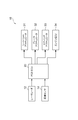
- the PCS system 10 of the present embodiment includes a laser radar 12, an image sensor 14, a PCS ECU 20, a seat belt actuator 31, a brake actuator 32, an airbag actuator 33, and an engine ECU 34.
- the laser radar 12 measures the position, distance, and relative speed of an obstacle such as another vehicle that is an object ahead of the host vehicle.
- the image sensor 14 is composed of a CMOS camera or a CCD camera, images a target object ahead of the host vehicle, and detects the state of the target object. Note that the measurement means for the positional relationship and the speed relationship between the vehicle and the object may use other means such as a stereo camera in addition to the laser radar 12.
- the PCS ECU 20 determines the possibility of contact and its timing from information such as the relative speed with the object obtained by the laser radar 12 and the image sensor 14, and controls various safety devices such as the brake actuator 32. Control the operation.
- the seat belt actuator 31 increases the safety of the driver by increasing the tension of the seat belt when there is a possibility of contact according to the command signal of the PCS ECU 20.
- the brake actuator 32 decelerates the host vehicle at the timing calculated by the PCS ECU 20 according to the situation.
- the airbag actuator 33 expands the airbag and enhances the driver's safety when there is a possibility of contact according to a command signal from the PCS ECU 20.
- the engine ECU 34 controls the engine of the host vehicle according to a command signal from the PCS ECU 20.
- Vr is the relative speed between the object and the host vehicle when the brake is operated.
- the set acceleration (deceleration when negative value) a generated by the operation of the brake is a step response and the time until the collision is t, the following equation (2) is established.
- the same deceleration amount is obtained regardless of the relative speed Vr and the deceleration a.
- the following equation (1) is established assuming that the distance to the object at the time of brake operation is D, and that the brake operation timing is before the contact TTC.
- an object is for example a preceding vehicle, and the acceleration and deceleration (deceleration when a negative value) is when the a T, the following equation (2 ') (5') (6 ') is established.
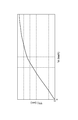
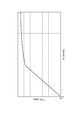
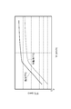
- the brake operation timing (instruction TTC) for obtaining the same deceleration amount irrespective of the relative speed Vr and the deceleration a is as follows. That is, in consideration of the delay time in the vehicle system, the PCS ECU 20 needs to give an instruction earlier than the operation TTC to be actually operated. Therefore, in consideration of the delay time, the relationship between the relative speed Vr, the operation TTC, and the instruction TTC when the object is stopped or moving at a constant speed is as shown in FIG. Further, the relationship between the relative speed Vr, the operation TTC, and the instruction TTC when the object is moving with deceleration is as shown in FIG. Note that the deceleration generated by the operation of the brake may or may not be preset.
- the PCS ECU 20 of the PCS system 10 includes the relative speed Vr between the host vehicle and the object, a preset deceleration amount ⁇ V due to the brake operation of the host vehicle, and the deceleration due to the brake operation of the host vehicle. Based on a, TTC, which is the timing of the brake operation of the host vehicle, is calculated.
- TTC which is the timing of the brake operation of the host vehicle.
- the PCS ECU 20 calculates the brake operation timing of the host vehicle based on the relative speed Vr and the deceleration a when the relative speed Vr is equal to or less than the set deceleration amount ⁇ V. To do.
- the relative speed Vr between the host vehicle and the object is as small as a deceleration amount ⁇ V or less set by the operation of the brake of the host vehicle, the host vehicle is decelerated by the deceleration a corresponding to the relative speed Vr. Done. Thereby, unnecessary deceleration can be suppressed.
- PCS ECU 20 based on the acceleration a T of the object to calculate the timing of the operation of the vehicle brakes. As a result, it is possible to secure a deceleration amount ⁇ V due to a more appropriate brake operation.
- the PCS ECU 20 calculates an instruction TTC that is a timing for operating the brake of the host vehicle based on a predetermined delay time in the system of the host vehicle. As a result, it is possible to ensure a more appropriate timing of brake operation of the host vehicle and a deceleration amount ⁇ V due to more appropriate brake operation.
- the brake control device of the present invention According to the brake control device of the present invention, according to the brake control device, it is possible to ensure the amount of change in speed due to more appropriate brake operation.
- PCS system 12 Laser radar 14 Image sensor 20 PCS ECU 31
- Seat belt actuator 32 Brake actuator 33
Landscapes
- Engineering & Computer Science (AREA)
- Chemical & Material Sciences (AREA)
- Combustion & Propulsion (AREA)
- Transportation (AREA)
- Mechanical Engineering (AREA)
- Automation & Control Theory (AREA)
- Regulating Braking Force (AREA)
Abstract
Description
また、本発明は、自車両と対象物との相対速度と、自車両のブレーキの作動による予め設定された速度の変化量と、自車両の前記ブレーキの作動による減速度とに基づいて、自車両のブレーキの作動のタイミングを算出するブレーキ作動タイミング算出工程を含むブレーキ制御方法である。










12 レーザレーダ
14 画像センサ
20 PCS ECU
31 シートベルトアクチュエータ
32 ブレーキアクチュエータ
33 エアバッグアクチュエータ
34 エンジンECU
Claims (5)
- 自車両と対象物との相対速度と、前記自車両のブレーキの作動による予め設定された速度の変化量と、前記自車両の前記ブレーキの作動による減速度とに基づいて、前記自車両の前記ブレーキの作動のタイミングを算出するブレーキ作動タイミング算出ユニットを備えたブレーキ制御装置。
- 前記ブレーキ作動タイミング算出ユニットは、前記相対速度が前記設定された速度の変化量以下の場合には、前記相対速度と、前記減速度とに基づいて、前記自車両の前記ブレーキの作動のタイミングを算出する、請求項1に記載のブレーキ制御装置。
- 前記ブレーキ作動タイミング算出ユニットは、前記対象物の加減速度に基づいて、前記自車両の前記ブレーキの作動のタイミングを算出する、請求項1又は2に記載のブレーキ制御装置。
- 前記ブレーキ作動タイミング算出ユニットは、前記自車両のシステム内の所定の遅れ時間に基づいて、前記自車両の前記ブレーキの作動のタイミングを算出する、請求項1~3のいずれか1項に記載のブレーキ制御装置。
- 自車両と対象物との相対速度と、前記自車両のブレーキの作動による予め設定された速度の変化量と、前記自車両の前記ブレーキの作動による減速度とに基づいて、前記自車両の前記ブレーキの作動のタイミングを算出するブレーキ作動タイミング算出工程を含むブレーキ制御方法。
Priority Applications (5)
| Application Number | Priority Date | Filing Date | Title |
|---|---|---|---|
| PCT/JP2011/058732 WO2012137326A1 (ja) | 2011-04-06 | 2011-04-06 | ブレーキ制御装置及びブレーキ制御方法 |
| DE112011105134.4T DE112011105134T5 (de) | 2011-04-06 | 2011-04-06 | Bremssteuergerät und Bremssteuerverfahren |
| JP2011542623A JP5333604B2 (ja) | 2011-04-06 | 2011-04-06 | ブレーキ制御装置及びブレーキ制御方法 |
| CN201180003226.1A CN102834306B (zh) | 2011-04-06 | 2011-04-06 | 制动器控制装置以及制动器控制方法 |
| US13/395,034 US9031755B2 (en) | 2011-04-06 | 2011-04-06 | Brake control device and brake control method |
Applications Claiming Priority (1)
| Application Number | Priority Date | Filing Date | Title |
|---|---|---|---|
| PCT/JP2011/058732 WO2012137326A1 (ja) | 2011-04-06 | 2011-04-06 | ブレーキ制御装置及びブレーキ制御方法 |
Publications (1)
| Publication Number | Publication Date |
|---|---|
| WO2012137326A1 true WO2012137326A1 (ja) | 2012-10-11 |
Family
ID=46966735
Family Applications (1)
| Application Number | Title | Priority Date | Filing Date |
|---|---|---|---|
| PCT/JP2011/058732 Ceased WO2012137326A1 (ja) | 2011-04-06 | 2011-04-06 | ブレーキ制御装置及びブレーキ制御方法 |
Country Status (5)
| Country | Link |
|---|---|
| US (1) | US9031755B2 (ja) |
| JP (1) | JP5333604B2 (ja) |
| CN (1) | CN102834306B (ja) |
| DE (1) | DE112011105134T5 (ja) |
| WO (1) | WO2012137326A1 (ja) |
Cited By (1)
| Publication number | Priority date | Publication date | Assignee | Title |
|---|---|---|---|---|
| WO2015075836A1 (ja) * | 2013-11-25 | 2015-05-28 | トヨタ自動車株式会社 | 衝突回避支援装置 |
Families Citing this family (4)
| Publication number | Priority date | Publication date | Assignee | Title |
|---|---|---|---|---|
| JP2016084049A (ja) * | 2014-10-27 | 2016-05-19 | トヨタ自動車株式会社 | 車両走行制御装置 |
| CN104890612A (zh) * | 2015-05-20 | 2015-09-09 | 浙江吉利汽车研究院有限公司 | 一种汽车安全带卷收装置 |
| US11370439B2 (en) * | 2017-02-13 | 2022-06-28 | Hitachi Astemo, Ltd. | Vehicle travel control device, and vehicle travel control system |
| CN111497802B (zh) * | 2019-01-31 | 2021-08-17 | 宏碁股份有限公司 | 刹车控制方法、刹车系统及车辆 |
Citations (4)
| Publication number | Priority date | Publication date | Assignee | Title |
|---|---|---|---|---|
| JP2003054394A (ja) * | 2001-06-06 | 2003-02-26 | Nissan Motor Co Ltd | 車両用制動制御装置 |
| JP2004164189A (ja) * | 2002-11-12 | 2004-06-10 | Nissan Motor Co Ltd | 車両用報知装置 |
| JP2007062604A (ja) * | 2005-08-31 | 2007-03-15 | Toyota Motor Corp | 車両用自動制動装置 |
| JP2008285095A (ja) * | 2007-05-21 | 2008-11-27 | Honda Motor Co Ltd | 車両操作支援装置 |
Family Cites Families (9)
| Publication number | Priority date | Publication date | Assignee | Title |
|---|---|---|---|---|
| JP2005263026A (ja) | 2004-03-18 | 2005-09-29 | Toyota Motor Corp | プリクラッシュセーフティ制御最適化方法及び装置 |
| JP4379184B2 (ja) * | 2004-04-08 | 2009-12-09 | 日産自動車株式会社 | 車両の制動制御装置 |
| JP4466571B2 (ja) * | 2005-05-12 | 2010-05-26 | 株式会社デンソー | ドライバ状態検出装置、車載警報装置、運転支援システム |
| DE102005033087A1 (de) * | 2005-07-15 | 2007-01-25 | Robert Bosch Gmbh | Verfahren und Vorrichtung zur Vermeidung von Auffahrunfällen |
| KR100981119B1 (ko) * | 2006-02-28 | 2010-09-08 | 도요타 지도샤(주) | 차량 구동 장치 및 차량 구동 장치의 제어 방법 |
| JP2007245835A (ja) | 2006-03-14 | 2007-09-27 | Mazda Motor Corp | 車両の走行制御装置 |
| JP4376882B2 (ja) * | 2006-09-01 | 2009-12-02 | トヨタ自動車株式会社 | 車両の制御装置 |
| JP4412356B2 (ja) * | 2007-06-13 | 2010-02-10 | 株式会社デンソー | 車両用衝突緩和装置 |
| CN201424012Y (zh) * | 2009-05-27 | 2010-03-17 | 北京工业大学 | 基于单目机器视觉的汽车主动安全系统 |
-
2011
- 2011-04-06 WO PCT/JP2011/058732 patent/WO2012137326A1/ja not_active Ceased
- 2011-04-06 JP JP2011542623A patent/JP5333604B2/ja active Active
- 2011-04-06 US US13/395,034 patent/US9031755B2/en active Active
- 2011-04-06 DE DE112011105134.4T patent/DE112011105134T5/de active Pending
- 2011-04-06 CN CN201180003226.1A patent/CN102834306B/zh not_active Expired - Fee Related
Patent Citations (4)
| Publication number | Priority date | Publication date | Assignee | Title |
|---|---|---|---|---|
| JP2003054394A (ja) * | 2001-06-06 | 2003-02-26 | Nissan Motor Co Ltd | 車両用制動制御装置 |
| JP2004164189A (ja) * | 2002-11-12 | 2004-06-10 | Nissan Motor Co Ltd | 車両用報知装置 |
| JP2007062604A (ja) * | 2005-08-31 | 2007-03-15 | Toyota Motor Corp | 車両用自動制動装置 |
| JP2008285095A (ja) * | 2007-05-21 | 2008-11-27 | Honda Motor Co Ltd | 車両操作支援装置 |
Cited By (3)
| Publication number | Priority date | Publication date | Assignee | Title |
|---|---|---|---|---|
| WO2015075836A1 (ja) * | 2013-11-25 | 2015-05-28 | トヨタ自動車株式会社 | 衝突回避支援装置 |
| US10529237B2 (en) | 2013-11-25 | 2020-01-07 | Toyota Jidosha Kabushiki Kaisha | Collision-avoidance support device |
| DE112013007632B4 (de) | 2013-11-25 | 2023-06-29 | Toyota Jidosha Kabushiki Kaisha | Kollisionsvermeidungsunterstützungsvorrichtung |
Also Published As
| Publication number | Publication date |
|---|---|
| JPWO2012137326A1 (ja) | 2014-07-28 |
| US9031755B2 (en) | 2015-05-12 |
| CN102834306A (zh) | 2012-12-19 |
| JP5333604B2 (ja) | 2013-11-06 |
| DE112011105134T5 (de) | 2014-05-15 |
| US20120259525A1 (en) | 2012-10-11 |
| CN102834306B (zh) | 2015-11-25 |
Similar Documents
| Publication | Publication Date | Title |
|---|---|---|
| CN105835819B (zh) | 车辆制动控制装置 | |
| JP5572657B2 (ja) | 車両の運転支援装置 | |
| JP5552955B2 (ja) | 車両制御装置 | |
| US20120226423A1 (en) | Vehicle driving support apparatus | |
| US10780916B2 (en) | Lane departure suppression device | |
| JP5417832B2 (ja) | 車両用運転支援装置 | |
| CN106030336A (zh) | 车辆周围状况识别设备和车辆控制设备 | |
| CN108602494A (zh) | 车辆控制装置以及车辆控制方法 | |
| WO2017111147A1 (ja) | 走行支援装置及び走行支援方法 | |
| CN107848500A (zh) | 车辆的碰撞避免控制装置以及碰撞避免控制方法 | |
| JP6086160B2 (ja) | 衝突回避支援装置 | |
| JP5333604B2 (ja) | ブレーキ制御装置及びブレーキ制御方法 | |
| JPWO2014192368A1 (ja) | 車両の制御装置及び車両の走行制御システム | |
| JP2018043576A (ja) | 車両制御装置、車両制御方法、および車両制御プログラム | |
| US9643576B2 (en) | Collision avoidance assist device and collision avoidance assist method | |
| JP2012226635A (ja) | 車両の衝突予防安全装置 | |
| JP4997778B2 (ja) | 乗員保護装置 | |
| JP2018521401A (ja) | 車両用の衝突までの時間の改善された計算 | |
| JP2011118723A (ja) | 車両の衝突を回避するための装置 | |
| JP4850963B1 (ja) | 車両の運転支援装置 | |
| CN107848502B (zh) | 车辆的碰撞避免控制装置以及碰撞避免控制方法 | |
| JP7388342B2 (ja) | 制動力制御装置 | |
| WO2017014112A1 (ja) | 車両の衝突回避制御装置および衝突回避制御方法 | |
| KR101519292B1 (ko) | 차량 충돌 방지 방법 | |
| JP2017114215A (ja) | シフト位置判定装置 |
Legal Events
| Date | Code | Title | Description |
|---|---|---|---|
| WWE | Wipo information: entry into national phase |
Ref document number: 201180003226.1 Country of ref document: CN |
|
| ENP | Entry into the national phase |
Ref document number: 2011542623 Country of ref document: JP Kind code of ref document: A |
|
| WWE | Wipo information: entry into national phase |
Ref document number: 13395034 Country of ref document: US |
|
| 121 | Ep: the epo has been informed by wipo that ep was designated in this application |
Ref document number: 11863231 Country of ref document: EP Kind code of ref document: A1 |
|
| WWE | Wipo information: entry into national phase |
Ref document number: 1120111051344 Country of ref document: DE Ref document number: 112011105134 Country of ref document: DE |
|
| 122 | Ep: pct application non-entry in european phase |
Ref document number: 11863231 Country of ref document: EP Kind code of ref document: A1 |