WO2012137286A1 - 医療用ポート、及びそれを用いた栄養剤用容器並びに栄養剤供給セット - Google Patents
医療用ポート、及びそれを用いた栄養剤用容器並びに栄養剤供給セット Download PDFInfo
- Publication number
- WO2012137286A1 WO2012137286A1 PCT/JP2011/058534 JP2011058534W WO2012137286A1 WO 2012137286 A1 WO2012137286 A1 WO 2012137286A1 JP 2011058534 W JP2011058534 W JP 2011058534W WO 2012137286 A1 WO2012137286 A1 WO 2012137286A1
- Authority
- WO
- WIPO (PCT)
- Prior art keywords
- communication member
- container
- medical port
- port
- thin film
- Prior art date
- Legal status (The legal status is an assumption and is not a legal conclusion. Google has not performed a legal analysis and makes no representation as to the accuracy of the status listed.)
- Ceased
Links
Images























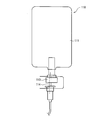
Classifications
-
- A—HUMAN NECESSITIES
- A61—MEDICAL OR VETERINARY SCIENCE; HYGIENE
- A61J—CONTAINERS SPECIALLY ADAPTED FOR MEDICAL OR PHARMACEUTICAL PURPOSES; DEVICES OR METHODS SPECIALLY ADAPTED FOR BRINGING PHARMACEUTICAL PRODUCTS INTO PARTICULAR PHYSICAL OR ADMINISTERING FORMS; DEVICES FOR ADMINISTERING FOOD OR MEDICINES ORALLY; BABY COMFORTERS; DEVICES FOR RECEIVING SPITTLE
- A61J1/00—Containers specially adapted for medical or pharmaceutical purposes
- A61J1/05—Containers specially adapted for medical or pharmaceutical purposes for collecting, storing or administering blood, plasma or medical fluids ; Infusion or perfusion containers
- A61J1/10—Bag-type containers
-
- A—HUMAN NECESSITIES
- A61—MEDICAL OR VETERINARY SCIENCE; HYGIENE
- A61J—CONTAINERS SPECIALLY ADAPTED FOR MEDICAL OR PHARMACEUTICAL PURPOSES; DEVICES OR METHODS SPECIALLY ADAPTED FOR BRINGING PHARMACEUTICAL PRODUCTS INTO PARTICULAR PHYSICAL OR ADMINISTERING FORMS; DEVICES FOR ADMINISTERING FOOD OR MEDICINES ORALLY; BABY COMFORTERS; DEVICES FOR RECEIVING SPITTLE
- A61J1/00—Containers specially adapted for medical or pharmaceutical purposes
- A61J1/14—Details; Accessories therefor
- A61J1/1475—Inlet or outlet ports
- A61J1/1487—Inlet or outlet ports with friction fit, e.g. connecting tubes directly to a protruding port
-
- A—HUMAN NECESSITIES
- A61—MEDICAL OR VETERINARY SCIENCE; HYGIENE
- A61J—CONTAINERS SPECIALLY ADAPTED FOR MEDICAL OR PHARMACEUTICAL PURPOSES; DEVICES OR METHODS SPECIALLY ADAPTED FOR BRINGING PHARMACEUTICAL PRODUCTS INTO PARTICULAR PHYSICAL OR ADMINISTERING FORMS; DEVICES FOR ADMINISTERING FOOD OR MEDICINES ORALLY; BABY COMFORTERS; DEVICES FOR RECEIVING SPITTLE
- A61J1/00—Containers specially adapted for medical or pharmaceutical purposes
- A61J1/14—Details; Accessories therefor
- A61J1/20—Arrangements for transferring or mixing fluids, e.g. from vial to syringe
- A61J1/2003—Accessories used in combination with means for transfer or mixing of fluids, e.g. for activating fluid flow, separating fluids, filtering fluid or venting
- A61J1/2048—Connecting means
- A61J1/2051—Connecting means having tap means, e.g. tap means activated by sliding
Definitions
- the present invention relates to a medical port that is fixed to a container body portion of a container for a nutrient solution and that allows the inside and outside of the container body portion to communicate with each other, a nutrient solution container in which the medical port is fixed to the container body portion, and a nutrient solution Regarding supply set.
- Enteral nutrition therapy and parenteral nutrition therapy are known as methods for administering nutrition and drugs to patients without oral administration.
- enteral nutrition therapy a tube passed from the patient's nasal cavity to the stomach or duodenum (commonly called a “nasal tube”) or a gastric fistula formed on the patient's abdomen (percutaneousaneEndoscopic treatment).
- a liquid (generally referred to as “enteral nutrition”) such as a nutrient, liquid food, or drug is administered via a tube (commonly referred to as “PEG tube”) inserted in a “Gastrostomy”.
- infusion liquid containing nutritional components such as glucose and drug components is administered via an infusion line (liquid feeding circuit) inserted into a patient's vein.
- FIG. 20 shows a schematic configuration diagram of an example of an enteral nutrition set used in conventional enteral nutrition therapy.
- the container body 101 of the nutrient solution container 100 is filled with a nutrient solution.
- a thin film (not shown) is attached to the mouth portion 102 through which the nutrient of the container main body 101 flows out, and the inside of the container main body 101 is sealed.
- the plastic connecting needle 104 is pierced into the cap 105 attached to the mouth, and the thin film is pierced. Thereby, the nutrient can be sent into the body through the tube connected to the connecting needle 104.
- FIG. 21 shows a schematic configuration diagram of an example of an infusion set used in conventional parenteral nutrition therapy.
- the bag body 111 of the bag 110 is filled with a liquid material containing nutritional components and pharmaceutical components.
- the connection needle 114 is punctured into the connection needle port 113. Thereby, a liquid substance can be sent into the body through a tube connected to the connection needle 114 (see Patent Document 1).
- the present invention provides a medical port that solves the above-described problem of erroneous connection and that can provide a nutrient solution container that can be sanitized with a simple operation for supplying a liquid material such as a nutrient solution.
- a container for nutrients and a nutrient supply set were provided.
- the medical port of the present invention is A medical port fixed to the container body of the nutrient container and capable of communicating inside and outside of the container body, A port body portion including a through hole, a side wall portion fixed to the container body portion, and a connection portion capable of maintaining a connection state with the connector; It is attached to the port main body, and is disposed on an extension line of the through hole in the container main body in a state where the medical port is fixed to the container main body, and the liquid substance in the container main body is used for the nutrient
- a thin film that blocks outflow from the container, A bridge connected to the port body and capable of being broken or deformed; A communication member that is partially inserted into the through-hole and connected to the port body via the bridge.
- the communication member includes a puncture portion that allows the thin film to be broken when the communication member is pushed into the container main body and the bridge is broken or deformed, and the container main body in a state where the thin film is broken. And a flow path that allows the liquid in the section to flow out of the nutrient container.
- the nutrient container of the present invention is A container body including a flexible bag-shaped member; And a medical port of the present invention fixed to the container main body.
- the nutrient supply set of the present invention is A nutrient container of the present invention;
- a liquid supply circuit including a connector having an engagement portion engageable with the connection portion of the medical port and a liquid supply tube connected to the connector;
- a liquid feeding circuit used for parenteral nutrition therapy is erroneously connected to a nutrient container, and supply of a liquid substance such as a nutrient is a simple operation. It is possible to provide a medical port that can provide a nutrient solution container that can be hygienically provided, a nutrient solution container using the medical port, and a nutrient supply set.
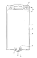
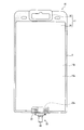
- FIG. 1 is a front view showing an example of a nutrient container according to Embodiment 1.
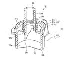
- FIG. 2A is an enlarged perspective view showing an example of the medical port of the present invention constituting the nutrient solution container shown in FIG.
- FIG. 2B is a partially enlarged view of the medical port shown in FIG. 2A.
- FIG. 2C is a plan view of the medical port shown in FIG. 2A.
- 2D is a bottom view of the medical port shown in FIG. 2A.
- 2E is a side view of the medical port shown in FIG. 2A.
- FIG. 2F is another side view of the medical port shown in FIG. 2A.
- 2G is a cross-sectional view of the medical port shown in FIG. 2A.
- FIG. 2H is another cross-sectional view of the medical port shown in FIG. 2A.
- 3A is an enlarged perspective view illustrating a bridge and a communication member of the medical port illustrated in FIG. 2A.
- 3B is a cross-sectional view taken along the line AA ′ of FIG. 3A.
- FIG. 3C is a perspective view illustrating another example of the bridge and the communication member.
- FIG. 3D is a perspective view illustrating another example of a bridge and a communication member.
- FIG. 3E is a perspective view illustrating another example of the bridge and the communication member.
- FIG. 3F is a perspective view illustrating another example of the bridge and the communication member.
- FIG. 3G is a perspective view illustrating another example of a bridge and a communication member.
- FIG. 4 is a cross-sectional view showing a state immediately before the liquid feeding circuit is connected to the medical port shown in FIG. 2A.
- FIG. 5 is a cross-sectional view showing a state in the middle of connection of the liquid feeding circuit to the medical port shown in FIG. 2A.
- 6A is a cross-sectional view showing a state in which the thin film is broken by the communication member of the medical port shown in FIG. 2A.
- 6B is a partially enlarged view of the medical port and the liquid delivery circuit shown in FIG. 6A.
- FIG. 7A is a perspective view of an example of a connector connected to the medical port shown in FIG. 2A.
- FIG. 7B is a plan view of the connector shown in FIG. 7A.
- FIG. 7C is a bottom view of the connector shown in FIG.
- FIG. 7A is a side view of the connector shown in FIG. 7A.
- FIG. 7E is another side view of the connector shown in FIG. 7A.
- FIG. 8 is a front view showing an example of a nutrient container according to the second embodiment.
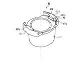
- FIG. 9A is a perspective view of a protective cover constituting the nutrient solution container shown in FIG. 8.
- FIG. 9B is another perspective view of the protective cover shown in FIG. 9A.
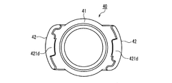
- FIG. 9C is a plan view of the protective cover shown in FIG. 9A.
- FIG. 9D is a bottom view of the protective cover shown in FIG. 9A.
- FIG. 10 is a front view illustrating an example of a nutrient container according to the third embodiment.
- FIG. 10 is a front view illustrating an example of a nutrient container according to the third embodiment.
- FIG. 11A is an enlarged perspective view showing an example of the medical port of the present invention that constitutes the nutrient solution container shown in FIG. 10.
- FIG. 11B is a partially enlarged view of the medical port shown in FIG. 11A.
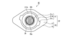
- FIG. 11C is a plan view of the medical port shown in FIG. 11A.
- FIG. 11D is a bottom view of the medical port shown in FIG. 11A.
- FIG. 11E is a side view of the medical port shown in FIG. 11A.
- FIG. 11F is another side view of the medical port shown in FIG. 11A.
- FIG. 12 is a perspective view illustrating a bridge and a communication member of the medical port illustrated in FIG. 11A.
- FIG. 13 is a cross-sectional view showing a state immediately before the liquid feeding circuit is connected to the medical port shown in FIG. 11A.
- 14 is a cross-sectional view showing a state in which the thin film is broken by the communication member of the medical port shown in FIG. 11A.
- FIG. 15 is a front view showing an example of a nutrient container according to the fourth embodiment.
- FIG. 16A is an enlarged perspective view showing an example of the medical port of the present invention constituting the nutrient solution container shown in FIG.
- FIG. 16B is a partially enlarged view of the medical port shown in FIG. 16A.
- FIG. 16C is a plan view of the medical port shown in FIG. 16A.
- FIG. 16D is a bottom view of the medical port shown in FIG. 16A.
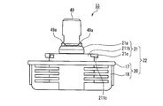
- FIG. 16E is a side view of the medical port shown in FIG. 16A.
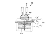
- FIG. 16F is another side view of the medical port shown in FIG. 16A.
- 17A is a cross-sectional view taken along the line BB ′ of the medical port shown in FIG. 16A.
- FIG. 17B is an enlarged cross-sectional view taken along the line CC ′ of the medical port shown in FIG. 16A.
- FIG. 18A is a partially enlarged cross-sectional view showing a state immediately before a liquid feeding circuit is connected to the medical port shown in FIG. 16A.
- FIG. 18B is a partially enlarged cross-sectional view illustrating a state in which the communication member of the medical port illustrated in FIG. 16A is being pushed into the thin film side.
- FIG. 18C is a partially enlarged cross-sectional view illustrating a state in which the communication member of the medical port illustrated in FIG. 16A is being pushed into the thin film side.
- FIG. 18D is a partially enlarged cross-sectional view illustrating a state in which the communication member of the medical port illustrated in FIG. 16A is being pushed into the thin film side.
- FIG. 19 is a front view showing another example of the nutrient container of the present invention.
- FIG. 20 is a schematic configuration diagram of an example of an enteral nutrition set used for conventional enteral nutrition therapy.
- FIG. 21 is a schematic configuration diagram of an example of an infusion set used for conventional parenteral nutrition therapy.
- the communication member includes a plurality of flow paths, and a plurality of holes are formed on the end surface opposite to the thin film side of the communication member.
- the communication member includes a plate-like portion at the end opposite to the thin film side, and a hole constituting a part of each flow path is formed in the plate-like portion.
- the fact that a plurality of holes are formed on the end face means that one through hole is divided into a plurality of small holes, and it is difficult to insert a connecting needle having a sharp tip into the through hole. Yes.
- the connecting member has a structure in which a connecting needle with a sharp tip is difficult to be inserted into the communicating member, the parenteral nutrition that sends a liquid substance into the body exclusively by piercing the connecting target with a sharp connecting tip.
- the problem of erroneous connection in which the therapy liquid delivery circuit is erroneously connected to a nutrient container used for enteral nutrition therapy, is more reliably solved.
- the communicating member includes a partition wall disposed on the thin film side of the plate-shaped portion and disposed so as to separate the spaces in the extending direction of the holes.
- the communication member is lighter than the case where the outer shape of the communication member is a substantially cylindrical shape, which is preferable because the communication member can be easily formed.
- a part of the communication member that is further away from the tip on the thin film side than the puncture portion protrudes in a direction perpendicular to the axial direction of the communication member.
- the protruding portion is in contact with the portion where the thin film is not broken and the communication member is effectively prevented from falling into the container main body portion.
- the communication member and the port main body are connected so that the bridge straddles a flow path that allows the liquid material filled in the container main body to flow out of the nutrient solution container. ing.
- the bridge since the bridge is disposed so as to cross the lumen (flow path) in the communication member, it is difficult to insert a connection needle having a sharp tip into the communication member, and the above-described erroneous connection can be prevented more reliably.
- a portion including a bridge from a connection portion (first connection portion) between the port body portion and the bridge to a connection portion (second connection portion) between the bridge and the communication member is provided.
- the portion including the bridge from the first connection portion to the second connection portion includes three thin portions and each of the three thin portions is bent and deformed, the communication member can be easily pushed into the container body portion side. Can do. If the number of thin portions is three, when the communicating member is pushed into the container body, the bridge may break due to the small number of thin portions, or the bending may occur due to the excessive number of thin portions. Complexity is suppressed and preferable.
- a protective cover that covers the communication member and includes an engaging portion that can be engaged with the connecting portion of the medical port is provided.
- Embodiment 1 In Embodiment 1, an example of the medical port of the present invention and an example of the nutrient container of the present invention using the medical port will be described with reference to FIGS. 1 to 7E.
- FIG. 1 is a front view showing an example of a nutrient container according to the present embodiment.
- 2A is an enlarged perspective view showing an example of the medical port of the present embodiment that constitutes the nutrient solution container shown in FIG. 1, and FIG. 2B is a portion of the medical port shown in FIG. 2A.
- 2C is a plan view of the medical port shown in FIG. 2A
- FIG. 2D is a bottom view of the medical port shown in FIG. 2A
- FIG. 2E is a medical view shown in FIG. 2A.
- 2F is another side view of the medical port shown in FIG. 2A
- FIG. 2G is a cross-sectional view of the medical port shown in FIG. 2A
- FIG. 2H is shown in FIG. 2A. It is other sectional drawing of the medical port made.
- the direction parallel to the central axis 19n of the communication member 19 is Z-axis
- the direction perpendicular to the Z-axis and the major axis direction of the top surface portion 17 is X-axis
- Z A direction perpendicular to the axis and the X axis is taken as a Y axis.
- the Z-axis direction is referred to as the “vertical direction”
- the Z-axis arrow side that is, the upper side in FIG. 2) is referred to as the “upper side” or the “tip side”
- the opposite side ie, the lower side in FIG. 2). It is called “lower side” or “proximal side”.
- the nutrient solution container 10 includes a container main body portion 11 including a flat bag-like flexible bag-shaped member 29, and a liquid material (including a nutrient solution filled in the container main body portion 11 ( (Not shown) and a medical port 13 fixed to the lower end of the container body 11.
- a suspending portion 28 for suspending the nutrient solution container 10 on a stand or the like is provided above the flexible bag-shaped member 29.
- the container body 11 is formed, for example, by stacking two soft resin sheets 16a and 16b and heat-sealing (thermally bonding) their outer peripheral edges to each other.
- Reference numeral 2 in FIG. 1 indicates a heat seal region (portion to which dots are added in FIG. 1) of the two soft resin sheets 16a and 16b.
- the medical port 13 is fixed to the container body 11 by being sandwiched between the soft resin sheets 16a and 16b.
- the medical port 13 is integrated with the soft resin sheets 16a and 16b by heat-sealing the heat seal region 2 of the soft resin sheets 16a and 16b while being disposed between the soft resin sheets 16a and 16b. Can do.
- the soft resin sheets 16a and 16b are not particularly limited, and conventionally known soft resin sheets used for, for example, medical soft containers can be used. Specifically, for example, a single-layer sheet made of vinyl chloride resin, polyethylene, ethylene-vinyl acetate copolymer, polyester, polybutadiene, polypropylene, polyamide, ethylene-methacrylate copolymer, or the like, or two layers of the above-mentioned single-layer sheet The laminated sheet laminated
- the layer structure of the laminated sheet include nylon / polyethylene, nylon / polypropylene, polyethylene terephthalate / polyethylene, polyethylene terephthalate / polypropylene, polypropylene / polyethylene, nylon / polypropylene / polyethylene, and the like.
- a laminated sheet for example, biaxially stretched polypropylene (OPP) / unstretched polypropylene (CPP) in which the same kind of resin having different grades (for example, film forming method, mechanical properties, or composition) is laminated. Good.
- OPP biaxially stretched polypropylene
- CPP unstretched polypropylene
- the surface on the side to be heat-sealed is made of a material having easy heat-sealability (for example, polypropylene).
- the thickness of the soft resin sheets 16a and 16b is not particularly limited, but is about 0.1 to 0.6 mm, for example. It is preferable that the soft resin sheets 16a and 16b have translucency (or translucency) because the liquid material in the flexible bag-like member 29 can be visually recognized from the outside. More preferably, the soft resin sheets 16a and 16b are transparent.
- the flexible bag-shaped member 29 As the liquid filled in the flexible bag-shaped member 29 flows out from the medical port 13, the pressure in the flexible bag-shaped member 29 decreases, but the flexible bag-shaped member 29 is soft. In the case of being formed of a soft material such as a resin sheet, the flexible bag-like member 29 is deformed with the outflow of the liquid material, and the outflow of the liquid material continues.
- the medical port 13 includes a port main body portion 22, a bridge 19a (see FIG. 2B) connected to the port main body portion 22, and the port main body portion 22 via the bridge 19a. And a thin film 16 (see FIGS. 2D, 2G, and 2H).
- the port main body 22, the bridge 19a, and the communication member 19 can be integrally formed by an injection molding method or the like.
- any part of the bridge 19a is torn off, and the thickness, width, etc. are appropriately determined according to the material.
- the port main body portion 22 includes a base portion 20 and a connection portion 21.
- the base portion 20 is erected in parallel with the Z axis from the top surface portion 17 including the surface parallel to the XY plane, and is fixed to the inner surface of the container main body portion 11 (see FIG. 1).
- the space 20 a communicates with the inside of the container main body 11 in a state where the medical port 13 is fixed to the container main body 11. As shown in FIG. 1, in a state where the medical port 13 is fixed to the container main body 11 (see FIG. 1), the entire connection portion 21 is disposed outside the container main body 11, and at least the base 20 One part is disposed in the container body 11.
- connection portion 21 includes a tubular portion 21a protruding above the top surface portion 17, a connection portion base portion 21b formed around the tubular portion 21a, and a pair of claw portions 21c. including.
- the tubular portion 21a has a through hole 21d (see FIGS. 2G and 2H) penetrating in the vertical direction.
- the through hole 21d communicates with the space 20a below the through hole 21d.
- a communication member 19 is connected to the tubular portion 21a of the port main body via a bridge 19a, and one of the communication members 19 is placed in a through hole 21d (see FIGS. 2G and 2H). Part is inserted. Therefore, the other part of the communication member 19 protrudes above the tubular portion 21a.
- the pair of claw portions 21c protrude outward from the outer peripheral surface of the connection portion base portion 21b (a direction parallel to the XY plane).
- the pair of claw portions 21c function as a connection portion that can maintain a connection state with a connector 25 of a liquid feeding circuit 27 (see FIG. 5 and the like) described later.
- FIG. 2C when the medical port 13 is viewed along a direction parallel to the Z direction, the pair of claw portions 21c are arranged on the long axis (X axis) of the top surface portion 17, for example.
- the pair of claw portions 21c has a lock recess 321g (FIG. 7A) of the connector 25 of the liquid feeding circuit 27 (see FIG. A lock projection 211c that can be fitted to the reference).
- the shape of the outer peripheral surface 18a of the side wall 18 surrounding the space 20a as viewed along the Z-axis direction is a substantially rhombus, and the widths at both ends of the substantially rhombus in the X direction are the tips. It gradually becomes narrower toward. Therefore, the side wall 18 is sandwiched between the two soft resin sheet materials 16a and 16b (see FIG. 1) constituting the container body 11, and the medical port 13 is fixed to the soft resin sheets 16a and 16b by heat sealing. At this time, it is preferable that the sealing failure is suppressed at the boundary between the location where the soft resin sheets 16a and 16b are in close contact with the location where the soft resin sheets 16a and 16b and the side wall portion 18 are in close contact with each other.
- the thin film 16 that blocks the flow of the liquid material between the through hole 21d and the space 20a is formed on the lower surface 21e of the connection portion 21 (the surface facing the space 20a of the connection portion 21). Is attached. Therefore, as shown in FIG. 1, even if the nutrient solution container 10 is directed so that the medical port 13 faces downward, the liquid in the nutrient solution container 10 leaks out of the nutrient solution container 10. Absent. Since the thin film 16 is affixed to the base end side end surface of the tubular part 21a, it can be said that it is arrange
- Examples of the material of the thin film 16 include aluminum foil, a laminated film made of paper and aluminum foil, and a resin film containing the same resin as that contained in the container main body 11.
- the resin film may be either a single layer film or a laminated film composed of a plurality of layers. Among these, from the viewpoint of ensuring high adhesion of the thin film 16 to the port main body portion 22 by heat welding, a resin film containing the same resin as that contained in the port main body portion 22 on the surface in contact with the port main body portion 22 is preferable.
- the thin film 16 may be transparent, translucent, or opaque, but in FIG. 2D, dots are attached to the thin film 16 for easy understanding (the same applies to FIGS. 11D and 16D). .)
- the method for adhering the thin film 16 to the port main body 22 is appropriately selected according to the material of the thin film 16 and the material of the port main body 22.
- FIG. 3A is a perspective view for explaining the bridge 19a and the communication member 19 constituting the medical port
- FIG. 3B is a cross-sectional view taken along the line AA ′ of the communication member 19 shown in FIG. 3A.
- the communication member 19 includes a plate-like portion 19e having a circular planar shape at the end opposite to the thin film 16 (see FIG. 2G) side, and a plurality of through holes 19d are formed in the plate-like portion 19e. .
- the communication member 19 has a plurality of partition walls 19c that divide the space on the thin film side into a plurality on the thin film side of the plate-like portion 19e.
- the partition walls 19c are arranged so as to separate the spaces in the extending direction of the holes 19d. Therefore, when the connector 25 of the liquid delivery circuit 27 (see FIG. 4 etc.) is connected to the medical port 13, the communication member 19 is pushed into the thin film side by the connector 25, and the thin film 16 is pierced by the puncture portion 19b. Is formed by having a plurality of partition walls 19c, and a plurality of spaces 19g and a plurality of through holes 19d (see FIG.
- the communication member 19 shown in FIGS. 3A and 3B has four partition walls 19c, and thus has four flow paths 19p. Since the four partition walls 19c are arranged at an equal angle along the circumferential direction and are integrated with each other, as shown in FIG. 4B, the sectional shape of the partition body including the plurality of partition walls 19c is substantially cross-shaped. It is.
- the communicating member 19 has a puncture portion 19b on the thin film 16 side of both ends in the axial direction (Z-axis direction).
- the tip of the puncture part 19b is sharp enough to break through the thin film 16.
- each of the plurality of partition walls 19 c has an inclined surface 19 m inclined toward the tip of the communication member 19 on the thin film side, and each inclined surface 19 m is on the thin film side of the communication member 19.
- a puncture portion 19b is formed which is focused on the tip 19f so as to be able to break through the thin film 16.
- the communication member 19 has a portion 19h that protrudes outward (radially) from the puncture portion 19b at any location farther from the thin film side tip 19f than the puncture portion 19b, in other words, In addition, it is preferable to have a portion 19h that protrudes in a direction perpendicular to the axial direction of the communication member 19 rather than the puncture portion 19b.
- the portion 19 h is in contact with the unbroken portion of the thin film 16, and the communication member 19 is prevented from falling into the container main body portion 11.
- the surface 19j of the portion 19h facing the thin film 16 is in contact with the unbroken portion of the thin film 16, and the communication member 19 falls into the container main body 11. Is prevented.
- the bridge 19a is provided so as to protrude outward (for example, in a direction orthogonal to the axial direction of the communication member 19) from the partition wall 19c.
- the bridge 19a can be easily broken.
- the communication member 19 includes a plurality of partition walls 19c arranged radially around the central axis 19n (see FIG. 2A), and the surface facing the inner peripheral surface of the tubular portion 21a of the plurality of partition walls 19c is along the circumferential direction.
- the bridges 19a may be provided so as to extend outward (radial direction) from every other partition wall 19c among the plurality of partition walls 19c.
- the bridge 19a is provided only on the two partition walls 19c separated from each other by 180 degrees.
- FIG. 4 shows a state immediately before the liquid feeding circuit 27 including the connector 25 and the flexible tube 26 connected to the connector 25 is connected to the connection portion 21 and the communication member 19 of the medical port 13. 5, while the liquid supply circuit 27 is connected to the connection portion 21 and the communication member 19, the liquid supply circuit 27 is connected to the connection portion 21 and the communication member 19 in FIGS. 6A and 6B. In the middle, the thin film 16 is broken.
- the connecting portion 21 and the communication member 19 are connected to a liquid feeding circuit 27 including a connector 25 described later with reference to FIGS. 7A to 7E. Therefore, a liquid feeding circuit for parenteral nutrition therapy that sends a liquid material into the body by piercing a connection target with a sharp tip exclusively into the body of the nutritional supplement container 10 ( The problem of erroneous connection that is connected to (see FIG. 1) is solved. Further, as shown in FIGS. 3A to 3G, a plurality of through holes 19d are formed on the end surface of the communication member 19 opposite to the puncture portion 19b side, and a connection needle having a sharp tip is formed in the through hole. Therefore, the erroneous connection can be prevented more reliably.
- the claw portion 21c of the medical port 13 is connected to the connector as will be described later. Since the connector 25 is engaged with the engaging portion 25, the connector 25 is fixed to the connecting portion 21, and the connector 25 is reliably prevented from coming off. Further, in a state where the claw portion 21c and the engaging portion of the connector 25 are engaged, the outer peripheral surface 212 of the tubular portion 21a is in close contact with the inner surface (large diameter portion 33a) of the connector 25 as shown in FIG. 6B. The connector 25 and the medical port 13 are connected without causing liquid leakage.
- connection state between the medical port 13 and the connector 25 may be maintained by various known structures, and the claw portion 21c including the lock convex portion 211c (FIG. 2F), which is a connection portion of the medical port 13. Etc.) and an engagement wall 321d including the lock recess 321g of the connector 25 (see FIG. 7A) may be used.
- the material other than the thin film 16 of the medical port 13 is not particularly limited, but is harder than the material of the soft resin sheets 16a and 16b.
- polyethylene (PE), polypropylene (PP), polyacetal (POM), polyethylene terephthalate. (PET), polycarbonate (PC), etc. are mentioned.
- FIG. 7A is a perspective view showing a schematic configuration of an example of the connector 25 connected to the medical port of the present invention
- FIG. 7B is a plan view of the connector 25 shown in FIG. 7A
- FIG. 7A is a bottom view of the connector 25 shown in FIG. 7A
- FIG. 7D is a side view of the connector 25 shown in FIG. 7A
- FIG. 7E is another side view of the connector 25 shown in FIG. 7A.
- the female connector 25 includes an insertion portion 33, a liquid feeding tube connection portion 30, a flange portion 32, and a grip portion 31.
- the connector 25 is connected to the medical port 13 of the nutrient solution container 10 (see FIG. 1), so that the flexible tube 26 (FIGS. 4 to 6B, etc.) connected to the inside of the container body 11 and the connector 25 is connected. Communication) with the internal cavity of the reference).
- An alternate long and short dash line 151 is the central axis of the insertion portion 33 and the liquid feeding tube connection portion 30, the direction of the central axis 151 is the vertical direction, and the upper side of FIG. 7A (the side connected to the medical port) is “upper side”. The lower side of the drawing will be called “lower side”.
- the connector 25 has a substantially cylindrical shape as a whole, and the insertion portion 33 in the vicinity of the upper end thereof has a large-diameter portion 33a having an inner diameter equal to or slightly smaller than the maximum outer diameter of the tubular portion 21a of the medical port 13.
- a small-diameter portion 33b having an inner diameter smaller than the outer diameter of the plate-like portion 19e (see FIG. 3A) of the communication member 19 and the inner diameter of the large-diameter portion 33a is provided below the large-diameter portion 33a.
- the tubular portion 21a of the medical port 13 Since the inner diameter of the large-diameter portion 33a is equal to or slightly smaller than the maximum outer diameter of the cylindrical portion 21a, the tubular portion 21a of the medical port 13 is pushed into the insertion portion 33 of the connector 25, and the connector 25, the medical port 13, When the is connected, the outer peripheral surface 212 of the tubular portion 21a is in close contact with the inner peripheral surface of the large-diameter portion 33a (see FIG. 6B). Therefore, the medical port 13 and the connector 25 can be reliably connected without causing leakage of the liquid material.
- the insertion part 33 of the connector 25 has the level
- the step surface 33c contacts the end surface 211a of the tubular portion 21a and the end surface 19k of the communication member 19 when the connector 25 is connected to the medical port 13 (see FIG. 6B).
- a substantially cylindrical liquid feeding tube connecting portion 30 is provided below the small diameter portion 33b.
- a pair of flanges 32 are formed around and above the large diameter portion 33a.
- the pair of collar portions 32 are symmetric with respect to the central axis 151.
- the flange portion 32 extends in a direction perpendicular to the central axis 151 and has a lower end of the arc-shaped wall 321 and an upper end of the large-diameter portion 33a. It has a connecting part 322 that connects.
- the arc-shaped wall 321 includes a passing region 321a, an engaging region 321b, and a non-passing region 321c due to the difference in the shape of the inner peripheral surface facing the central axis 151.
- the inner peripheral surface of the passing region 321a is a part of a cylindrical surface having a diameter DF21
- the inner peripheral surface of the non-passing region 321c is a part of a cylindrical surface having a diameter DF23 (DF23 ⁇ DF21). is there.
- FIG. 7B the inner peripheral surface of the passing region 321a is a part of a cylindrical surface having a diameter DF21
- the inner peripheral surface of the non-passing region 321c is a part of a cylindrical surface having a diameter DF23 (DF23 ⁇ DF21). is there.
- the engagement region 321b between the pass region 321a and the non-pass region 321c is circumferentially connected to the upper end of the pass region 321a and the upper end of the non-pass region 321c.
- An extending engagement wall 321d is provided.
- An inner peripheral surface of the engagement wall 321d facing the central axis 151 is a part of a cylindrical surface having a diameter DF22 (DF22 ⁇ DF21). Since the engaging region 321b includes the engaging wall 321d, the region between the engaging wall 321d and the crossing portion 322 is depressed in a concave shape.
- the region between the engagement wall 321d and the crossing portion 322 is recessed relative to the central axis 151 relative to the engagement wall 321d to form a recess 321e.
- the non-passing region 321c adjacent to the engaging region 321b in the circumferential direction protrudes in the direction of the central axis 151 relative to the concave portion 321e, and constitutes a convex portion 321f.
- a lock recess 321g that is recessed in a concave shape is formed on the lower surface (the surface on the recess 321e side, the surface facing the crossover portion 322) of the end of the engagement wall 321d on the non-passing region 321c side.
- a through hole 220 (see FIG. 7C) that penetrates in the thickness direction of the crossover portion 322 is formed in a portion of the crossover portion 322 that faces the engaging wall 321d, but the through hole 220 may not be formed. Good.
- a pair of grip portions 31 are formed around the insertion portion 33 so as to protrude outward from the outer peripheral surface of the insertion portion 33 (in a direction orthogonal to the central axis 151).
- the rotation operation is performed with the pair of grip portions 31.
- the communication member 19 is moved toward the thin film side 16 while the connector 25 is attached to the medical port 13 so that the communication member 19 is inserted into the insertion portion 33 of the connector 25.
- the bridge 19a (see FIG. 2B and the like) is broken, and the thin film 16 is broken at the puncture portion 19b of the communication member 19. That is, the communication member 19 is pushed into the container body 11 (see FIG. 1) by an operation for connecting the connector 25 to the medical port 13.
- the lock protrusion 211c (see FIG. 2F and the like) is engaged with the rotation of the connector 25.
- the wall 321d slides on the surface 321h while being pressed against the surface 321h on the crossing portion 322 side, and then fits into the lock recess 321g (see FIG. 7A).
- the state where the connector 25 is connected to the medical port 13 can be stably held by fitting the lock protrusion 211c and the lock recess 321g.
- the connector 25 is simply connected to the medical port 13 while the communication member 19 of the medical port 13 is pushed into the container body 11 by the connector 25. Since the nutrient container 10 and the liquid feeding circuit 27 can be communicated with each other, the liquid material can be supplied in a sanitary manner with a simple operation.
- the connector 25 is provided with a convex portion 321f (see FIG. 7A) adjacent to the lock concave portion 321g in which the claw portion 21c (see FIG. 2F and the like) is housed, the claw portion 21c of the medical port 13 is provided. Is inserted into the lock recess 321g and further moved until it comes into contact with the projection 321f, the claw portion 21c and the engagement wall 321d can be reliably engaged.
- the rotation of the connector 25 with respect to the medical port 13 is restricted by the claw portion 21c of the medical port 13 coming into contact with the convex portion 321f of the connector 25.
- the claw portion 21c and the engagement wall 321d can be reliably engaged with each other by a simple operation of rotating the connector 25 with respect to the medical port 13 until the rotation is restricted.
- the hardness of the connector 25 measured according to JIS-K7202 is preferably R40 to R140 from the viewpoint of improving the connection workability of the liquid supply tube 26 having flexibility to the liquid supply tube connection part 30.
- R50 to R100 are more preferable.
- the form of the communication member 19 is not limited to that shown in FIGS. 3A and 3B.
- the communication member 19 has three through holes 19d in the plate-like portion 19e and three partition walls 19c on the thin film side of the plate-like portion 19e. It may have.
- all the partition walls 19c are provided with bridges 19a, and the plurality of bridges 19a are arranged at equal intervals in the circumferential direction. If the communication member 19 is stably supported by (see), it is sufficient that at least one bridge 19a is provided.
- the communication member 19 has two through holes 19d in the plate-like portion 19e, one partition wall 19c on the thin film side of the plate-like portion 19e, and two flow paths. It may be a thing.
- bridges 19a are formed on the surface of the partition wall 19c facing the inner peripheral surface of the tubular portion 21a. That is, in the communication member 19 shown in FIG. 3D, a pair of bridges 19a is provided symmetrically with respect to the central axis of the communication member 19 in one partition wall 19c. If the communication member 19 is stably supported by (see), it is sufficient that at least one bridge 19a is provided.
- the communication member 19 has a substantially cylindrical shape, and has two to four through holes 19d, so that the inner cavity is divided into two to four. It may have a flow path.
- the communication member 19 has a substantially cylindrical shape, and the outer shape when the end surface of the communication member 19 is viewed from the puncture portion 19b side in the longitudinal direction is, for example, circular. From the viewpoint that a large hole can be formed in the thin film 16 by puncturing the communication member 19.
- the communication member 19 shown in FIGS. 3E to 3G if the communication member 19 is stably supported by the port body portion (see FIG. 2 and the like), at least one bridge 19a is provided on the outer peripheral surface thereof. What is necessary is just to be provided.
- FIG. 8 is a partial perspective view showing an example of a nutrient container according to the present embodiment.
- the medical port and nutrient solution container of the present embodiment have the medical port 13 of the first embodiment except that the medical port 13 further includes a protective cover 40 for protecting the communication member 19.
- the same components as those for the food port and the nutrient solution container are denoted by the same member numbers, and the description thereof is omitted.
- the communication member 19 since the communication member 19 is protected by the protective cover 40, it is possible to prevent external force from being applied to the communication member 19 when not desired. Therefore, an external force is applied to the communication member 19 when it is not desired, and the communication member 19 is pushed into the container main body 11 side (opening 22a side of the port main body 22), and the communication member 19 pushed into the container main body 11 side. It is possible to prevent the thin film 16 (see FIG. 2G and the like) from being broken.
- the protective cover 40 includes a cover body 41 that covers the communication member 19 from the outer surface side of the top surface portion 17 (see FIG. 2A), and a claw portion 21c of the medical port 13 (see FIG. 2A). And a pair of flange portions 42 including engaging walls 421d that can be engaged as engaging portions.
- the collar part 42 of the protective cover 40 has the same structure as the collar part of the connector 25.
- the protective cover 40 is placed so that the communication member 19 and the connecting portion base 21b (see FIG. 2A) are accommodated in the cover main body 41, and the protective cover 40 is rotated to lock the claw portion 21c of the medical port 13
- the 211c see FIG. 2F, etc.
- the lock recess 421g formed on the lower surface (surface on the recess 418 side) of the end of the engagement wall 421d on the non-passage region 421c side
- the protective cover 40 is attached to the medical port. 13 can be stably held.
- the liquid feeding circuit used for parenteral nutrition therapy is erroneously connected
- the supply of liquid substances such as nutrients can be simplified. It is hygienic by operation.
- the protective cover 40 is removed from the medical port 13, for example, a force for pushing the communication member 19 to the thin film 16 side is applied via the connector 25 to break the thin film 16, and the liquid feeding circuit 27 is connected to the medical port 13.
- the liquid can be supplied to the patient.
- FIG. 10 is a front view showing an example of a nutrient container according to the present embodiment.
- FIG. 11A is an enlarged perspective view showing an example of the medical port of the present embodiment that constitutes the nutrient solution container shown in FIG. 10, and FIG. 11B shows the medical port 43 shown in FIG. 11A.
- 11C is a partially enlarged view
- FIG. 11C is a plan view of the medical port 43 shown in FIG. 11A
- FIG. 11D is a bottom view of the medical port 43 shown in FIG. 11A
- FIG. 11E is shown in FIG.
- FIG. 11F is another side view of the medical port 43 shown in FIG. 11A.
- FIG. 12 is a perspective view for explaining a bridge and a communication member of the medical port 43 shown in FIG. 11A.
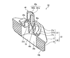
- the medical port and nutrient solution container of the present embodiment are provided with the attachment position of the thin film 16, the shape of the communication member 39, the shape of the bridge 39a, and the connection portion base 211b. Except for the difference in shape, they have the same configuration as the medical port and nutrient solution container of the first embodiment, and the same members are denoted by the same member numbers and description thereof is omitted.
- the thin film 16 is attached to the lower surface 18 b of the side wall portion 18. Therefore, in the nutrient container 10 (see FIG. 10), the liquid material between the space 20a surrounded by the through hole 21d and the side wall 18 of the tubular portion 21a and the inside of the container main body 11 (see FIG. 10). The distribution is blocked by the thin film 16. Therefore, as shown in FIG. 10, even if the nutrient solution container 10 is directed so that the medical port 53 faces downward, the liquid in the nutrient solution container 10 leaks out of the nutrient solution container 10. Absent. Since the thin film 16 is attached to the lower surface of the side wall 18 so as to close the opening 22a (see FIG. 10) of the port main body 22, it can be said that the thin film 16 is disposed on the extension line of the through hole 21d.
- the connecting portion base 211b (see FIG. 2A and the like) is integrated with the tubular portion 21a.
- a ridge line separating the connecting portion base 211b and the tubular portion 21a from each other.
- the connection portion base portion 211b protrudes upward from the top surface portion 17 and is provided away from the tubular portion 21a.
- a groove 211d exists between the tubular portion 21a and the connecting portion base 211b. Therefore, the medical port 43 of this embodiment is preferable because it is less likely to cause sink marks or the like during molding than the medical port 13 of Embodiment 1 and is easy to manufacture.
- the communication member 39 includes a cylindrical portion 39e on the side opposite to the thin film 16 (see FIG. 13) side.
- the cylindrical portion 39e has a part of the circumference that is visible when the communication member 39 is viewed in plan view from the end surface side opposite to the thin film side. And has a notch 39 h formed along the axial direction of the communication member 39.
- the outer surface of the cylindrical portion 39e is a part of a cylindrical surface having a diameter slightly smaller than the inner diameter of the tubular portion 21a.
- the communication member 39 has a puncture portion 39b on the thin film 16 side at both ends in the axial direction.
- the tip of the puncture part 39b is pointed to such an extent that it can break through the thin film.
- the communication member 39 has a pair of inclined surfaces 39m inclined toward the tip on the thin film side, and each inclined surface 39m converges on the tip 39f on the thin film side of the communication member 39.
- a puncture portion 39b that can break through the thin film 16 is formed.
- the inner cavity 39j of the communication member 39 causes the liquid material filled in the container main body 11 (see FIG. 10) to move out of the nutrient solution container (indicated by the arrow A). It functions as a flow path that can flow out.
- the port body 22, the bridge 39a, and the communication member 39 can be integrally formed by an injection molding method or the like.
- the bridge 39a passes through the notch 39h and straddles the inside and the outside of the tubular portion 39e, and the inner peripheral surface 39k of the communication member 39 and the tubular portion 21a of the connecting portion 21 Are connected.
- the bridge 39a is plastically deformed when a force is applied to the communication member 39 toward the thin film 16 (see FIG. 13) by pressing, and the bridge 39a does not return to its original shape even if it receives no pressing force.
- the thickness, width, and the like of the bridge 39a are appropriately determined according to the material so that plastic deformation is possible when the communication member 39 is pushed into the thin film 16 (see FIG. 13) side.
- the length of the bridge 39a is a length that allows the communication member 39 to move toward the thin film 16 to such an extent that the thin film 16 (see FIG. 13) can be pierced by the puncture portion 39b of the communication member 39. Cost.
- the shape of the bridge 39a seen when the communication member 39 is viewed in plan view from the end surface side opposite to the thin film side is For example, an S shape is preferable.
- the shape of the communication member 39 has a cylindrical shape such as a cylindrical shape in which one end portion in the longitudinal direction includes a puncture portion 39b and is sharp enough to break through the thin film 16.
- the width of the cutout portion 39h can be formed from the viewpoint that a large hole can be formed in the thin film 16 by puncturing the communication member 39. (The length in the direction perpendicular to the longitudinal direction of the notch 39h) is preferably slightly larger than the width of the portion present in the notch 39 of the bridge 39a.
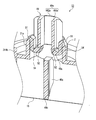
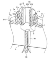
- FIG. 13 includes a connector 25 (see FIGS. 4 to 6A) and a flexible tube 26 (see FIG. 4) connected to the connector 25 with respect to the connection portion 21 and the communication member 39 of the medical port 43.
- a state before the liquid circuit 27 (see FIGS. 4 to 6A) is connected is shown, and FIG. 14 shows a state in which the thin film 16 is broken by the communication member 39. 13 to 14, the liquid feeding circuit 27 shown in FIGS. 4 to 6A is omitted.
- connection portion 21 and the communication member 39 are connected to the liquid feeding circuit 27 including the connector 25 described with reference to FIGS. 7A to 7E. Therefore, a liquid feeding circuit for parenteral nutrition therapy that sends a liquid material into the body by piercing a connection target with a sharp tip exclusively into the body of the nutritional supplement container 10 ( This solves the problem of erroneous connection such as that shown in FIG.
- a bridge 39a is disposed in the communication member 39 so as to cross the lumen (flow path) 39j in the communication member 39.
- the bridge 39a The communication member 39 and the tubular portion 21a (see FIGS. 11A and 11B and the like) of the port main body 22 are connected so as to straddle the road. Therefore, the connection needle having a sharp tip is difficult to be inserted into the communication member 39, and the erroneous connection can be prevented more reliably.
- the bridge 39a is plastically deformed, the thin film 16 is broken, and the medical port 43 is formed.
- the liquid feeding circuit 27 see FIG. 5
- the liquid can be supplied to the patient. Therefore, in the present embodiment as well as the first embodiment, not only can the solution of the erroneous connection that the liquid delivery circuit used for parenteral nutrition therapy is erroneously connected be solved, but also the supply of liquid substances such as nutrients can be achieved. Easy operation and hygienic.
- the bridge 39a is not limited to the one that does not return to its original shape even if it receives a pressing force against the communication member 39, and is deformed plastically. Or may be elastically deformed and may return to its original shape when it is no longer subjected to a pressing force.
- the bridge 39a can break the thin film 16 while the port main body portion 22 and the communication member 39 are connected, the communication member 39 falls into the container main body portion 11 (see FIG. 10) and becomes a liquid material.
- the bridge 39a may be broken.
- the medical port and nutrient container of the present embodiment may include the protective cover described in the second embodiment.
- FIG. 15 is a front view showing an example of a nutrient container according to the present embodiment.
- 16A is an enlarged perspective view showing an example of the medical port of the present embodiment constituting the nutrient solution container shown in FIG. 15, and
- FIG. 16B is a view of the medical port 53 shown in FIG. 16A.
- 16C is a partially enlarged view, FIG. 16C is a plan view of the medical port 53 shown in FIG. 16A, FIG. 16D is a bottom view of the medical port 53 shown in FIG. 16A, and FIG. FIG. 16F is another side view of the medical port 53 shown in FIG. 16A, and
- FIG. 17A is a BB ′ cross section of the medical port 53 shown in FIG. 16A.
- FIG. 17A is a BB ′ cross section of the medical port 53 shown in FIG. 16A.
- FIG. 17B is an enlarged cross-sectional view of CC ′ of the medical port 53 shown in FIG. 16A.
- the medical port and nutrient solution container of this embodiment are different from those of Embodiment 2 except that the attachment position of the thin film 16, the shape of the communication member 49, and the shape of the bridge 49a are different.
- the same components as those of the medical port and the nutrient container are denoted by the same member numbers, and the description thereof is omitted.
- the thin film 16 is attached to the lower surface 18b of the side wall 18. Therefore, in the nutrient container 10 (see FIG. 15), the liquid material between the space 20a surrounded by the through-hole 21d and the side wall 18 of the tubular portion 21a and the inside of the container main body 11 (see FIG. 15). The distribution is blocked by the thin film 16. Therefore, as shown in FIG. 15, even if the nutrient solution container 10 is directed so that the medical port 53 faces downward, the liquid in the nutrient solution container 10 leaks out of the nutrient solution container 10. Absent. Since the thin film 16 is attached to the lower surface 18b (see FIG. 17A) of the side wall portion 18 so as to close the opening 22a (see FIG. 15) of the port body portion 22, it is disposed on the extension line of the through hole 21d. I can say that.
- the communication member 49 includes a cylindrical portion 49e disposed on the side opposite to the thin film 16 (see FIG. 17A and the like) side.
- the cylindrical portions 49e are arranged so as to face each other, a pair of flat plate-like portions 491e arranged symmetrically with respect to the central axis of the cylindrical portion 49e, and a pair of curved plate-like portions 492e connecting them.
- the outer surface of each curved plate-like portion 492e is a part of a cylindrical surface having a diameter slightly smaller than the inner diameter of the tubular portion 21a, but the outer surface of the flat plate-like portion 491e is relatively tubular than the cylindrical surface. It has retreated in the direction away from the portion 21a, and constitutes a recess 493e.
- the communication member 49 includes a puncture portion 49b on the thin film side of the tubular portion 49e, and includes a partition wall 49c that divides the space in the tubular portion 21a into a plurality of portions.
- the width of the end portion on the thin film side of the partition wall 49c gradually decreases toward the tip, thereby forming a puncture portion 49b that is sharp enough to break through the thin film 16.
- the partition wall 49c is connected to the lower end of the curved plate-like portion 492e and is integrated with the tubular portion 49e. Therefore, when the tubular portion 49e is pushed into the thin film 16 side, the partition wall 49c. Is also pushed into the thin film 16 side.
- the main surface of the partition wall 49c is parallel to the main surface of the pair of flat plate portions 491e. Most of the partition wall 49c is disposed below (on the side closer to the thin film 16) the pair of bridges 49a that connect the respective lower ends of the flat plate portion 491e and the tubular portion 21a. When seen in a plan view from the end surface side opposite to the side, the partition wall 49c appears to be disposed between the pair of bridges 49a (see FIG. 16C).
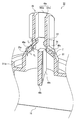
- a liquid feeding circuit 27 (see FIGS. 4 to 6A) including the connector 25 and the flexible tube 26 connected to the connector 25 is connected to the connection portion of the medical port 53 and the communication member 49.
- 18B to 18D show a state where the communication member 49 is being pushed into the thin film 16 side.
- the liquid feeding circuit 27 shown in FIGS. 4 to 6A is omitted.
- Connecting portion between the tubular portion 21a and bridge 49a of the port body portion thickness T 1 of the (first connecting portion) 51 is thinner than the thickness of the vicinity of the connecting portion 51 of the bridge 49a.
- the thickness T 2 of the bridge 49a and the connecting portion between the cylindrical portion 49e of the communicating member 49 (second connecting portion) 52 is thinner than the thickness of the vicinity of the connecting portion 52 of the bridge 49a.
- the bridge 49a for example the thickness contains a thin portion 54 of T 3 at the center thereof. Therefore, when a force is applied to the communication member 49 via the connector 25 (see FIG. 4 and the like) by pressing to the thin film 16 side, as shown in FIG. 18B to FIG.
- Three thin portions including the first connection portion 51, the second connection portion 52, and the thin portion 54 of the portion Z including the bridge 49a up to the connection portion 52 are bent and deformed, the communication member 49 is pushed into the thin film 16, and the thin film 16 is pierced by the puncture portion 49 b of the communication member 49.
- the thickness T 1 of the first connecting portion 51, the thickness T 2 of the second connecting portion 52, and the thickness of each part of the thickness T 3 and the bridge 49a of the thin portion 54 is appropriately determined depending on the material.
- the communication member 49 shown in FIG. 18D is further pushed into the thin film 16 side, and the claw portion 21c (see FIG. 16A etc.) and the engagement wall 321d of the connector 25 (engagement portion, see FIG. 7A etc.) are engaged.
- the end surface 49f opposite to the thin film 16 side of the communication member 49 is substantially flush with the open end surface 211a of the tubular portion 21a.
- a gap is formed between the outer surface of the flat plate portion 491e and the inner surface of the tubular portion 21a facing this.
- the folded bridge 49a is housed in the space surrounded by the gap, that is, the recess 493e (see FIG. 16B) and the inner peripheral surface of the tubular portion 21a.
- connection portion 21 and the communication member 49 are connected to the liquid feeding circuit 27 including the connector 25 described with reference to FIGS. 7A to 7E. Therefore, a liquid feeding circuit for parenteral nutrition therapy that sends a liquid material into the body by piercing a connection target with a sharp tip exclusively into the body of the nutritional supplement container 10 ( The problem of erroneous connection, as shown in FIG. 15, is solved.
- the liquid material can be supplied to the patient simply by bending and plastically deforming as necessary, tearing the thin film 16, and connecting the liquid feeding circuit 27 (see FIG. 4) to the medical port 53. Therefore, in the present embodiment as well as the first embodiment, not only can the solution of the erroneous connection that the liquid delivery circuit used for parenteral nutrition therapy is erroneously connected be solved, but also the supply of liquid substances such as nutrients can be achieved. Easy operation and hygienic.
- the thin portion 54 of the bridge 49a is one, and the first connecting portion 51, the second connecting portion 52, and the thin portion 54 are bent to communicate with each other.
- the member 49 is allowed to be pushed into the thin film 16 side, the bridge may include one or more thin portions.
- the connecting portion The shape of 51 and 52 and the number of thin portions are not particularly limited, but the number of thin portions in the portion Z is due to the fact that the bridge breaks due to the small number of thin portions or the number of thin portions is too large. From the viewpoint of preventing the bending from becoming complicated, three are preferable.
- the bridge 49a is bent and deformed when a force is applied to the communication member 49 toward the thin film side by pressing, and the thin film 16 is connected while the port main body portion 22 and the communication member 49 are connected. Since it can be torn, it is preferable that the communication member 49 falls into the container body 11 (see FIG. 15) and the communication member 49 is prevented from floating in the liquid material, but in this embodiment, the bridge 49a is It may break.
- the medical port and nutrient container of the present embodiment may include the protective cover described in the second embodiment.
- the container body 11 of the nutrient solution container 10 shown in FIGS. 1, 8, 10, and 15 is filled with a liquid material (not shown) such as a nutrient solution.
- the nutrient container 10 may be an empty container in which the liquid main body 11 is not filled.
- the container body 11 of the nutrient solution container 10 has an opening 23, a zip 23 a that reversibly opens and closes the opening 23 across the opening 23. (It is an engaging part that can be freely opened and closed. It is also called “chuck seal”).
- a hanging part (not shown) may be provided above the opening 23.
- the liquid feeding circuit connected to the container or constituting the nutrient solution supply set together with the nutrient solution container presses the flexible tube 26 to adjust the flow rate of the liquid material flowing through the flexible tube 26. It further includes components such as a regulator, a drip tube, a connector that can be connected to a nasal tube fixed to a patient, a cover of the connector, and the like, which are provided in a liquid feeding circuit used in conventionally known enteral nutrition therapy. Also good.
- a medical port of a nutrient container suitable for enteral nutrition therapy, a nutrient container using the same, and a nutrient supply set including the nutrient container can be provided.
Landscapes
- Health & Medical Sciences (AREA)
- Pharmacology & Pharmacy (AREA)
- Life Sciences & Earth Sciences (AREA)
- Animal Behavior & Ethology (AREA)
- General Health & Medical Sciences (AREA)
- Public Health (AREA)
- Veterinary Medicine (AREA)
- Hematology (AREA)
- Medical Preparation Storing Or Oral Administration Devices (AREA)
Abstract
本発明の医療用ポートは、栄養剤用容器の容器本体部に固定され、容器本体部の内外を連通させ得る医療用ポート(13)であって、貫通孔(2d)と、容器本体部へ固定される側壁部(18)と、コネクタとの接続状態を保持可能とする接続部(21)と、を含むポート本体部(22)と、ポート本体部に取り付けられ、医療用ポートが容器本体部に固定された状態で容器本体部内の前記貫通孔の延長線上に配置され、容器本体部内の液状物の栄養剤用容器外への流出を遮る薄膜(16)と、ポート本体部に連結され、破断または変形可能なブリッジ(19a)と、その一部が貫通孔(21d)内に挿入され、且つ、ポート本体部にブリッジを介して連結された、連通部材(19)とを含む。連通部材は、連通部材が容器本体部側に押し込まれてブリッジが破断または変形することにより薄膜を突き破り可能とする穿刺部と、薄膜が突き破られた状態で容器本体部内の液状物を栄養剤用容器外へ流出させ得る流路とを含む。
Description
本発明は、栄養剤用容器の容器本体部に固定され、容器本体部の内外を連通させ得る医療用ポート、及び当該医療用ポートが容器本体部に固定された栄養剤用容器、並びに栄養剤供給セットに関する。
経口によらずに患者に栄養や薬剤を投与する方法として経腸栄養療法や静脈栄養療法が知られている。経腸栄養療法では、患者の鼻腔から胃又は十二指腸にまで通されたチューブ(一般に「経鼻チューブ」と呼ばれる)又は患者の腹に形成された胃ろう(胃ろうを形成する施術を「Percutaneous Endoscopic Gastrostomy」と呼ぶ)に挿入されたチューブ(一般に「PEGチューブ」と呼ばれる)を介して栄養剤、流動食、又は薬剤などの液状物(一般に「経腸栄養剤」と呼ばれる)が投与される。また、静脈栄養療法では、患者の静脈に挿入された輸液ライン(送液回路)を介してブドウ糖などの栄養成分や薬剤成分を含む液状物(一般に「輸液」と呼ばれる)が投与される。
図20に、従来の経腸栄養療法に用いられる経腸栄養セットの一例の概略構成図を示している。栄養剤用容器100の容器本体101内には、栄養剤が充填されている。容器本体101の栄養剤を流出させる口部102には薄膜(図示せず)が取り付けられて、容器本体101内が密閉されている。体内に栄養剤を投与する際には、プラスチック製接続針104を口部に装着されたキャップ105に刺して上記薄膜を突き破る。このことにより、接続針104に接続されたチューブを通して体内に栄養剤を送ることができる。
図21に、従来の静脈栄養療法に用いられる輸液セットの一例の概略構成図を示している。バッグ110のバッグ本体111内には、栄養成分や薬剤成分を含む液状物が充填されている。体内に液状物を投与する際には、接続針114を接続針用ポート113に穿刺する。このことにより、接続針114に接続されたチューブを通して体内に液状物を送ることができる(特許文献1参照)。
上記のとおり、従来の経腸栄養療法においては、静脈栄養療法と同様に、先端が鋭利な接続針を接続対象に突き刺すことによって、栄養剤を体内に送る手法が採用される場合がある。そのため、キャップ105に接続針114を穿刺することが可能である。この場合、接続針114は、キャップ105及び薄膜を貫通し、口部102の内部に至ることになる。しかし、このような誤接続が行われると、胃や腸に供給されるべき栄養剤等が静脈に誤って供給されることになり、医療事故が発生する可能性があった。
本発明は、上記誤接続の問題を解決し、且つ、栄養剤等の液状物の供給が簡単な操作で衛生的に行える栄養剤用容器の提供を可能とする医療用ポート、及びそれを用いた栄養剤用容器、並びに栄養剤供給セットを提供する。
本発明の医療用ポートは、
栄養剤用容器の容器本体部に固定され、前記容器本体部の内外を連通させ得る医療用ポートであって、
貫通孔と、前記容器本体部へ固定される側壁部と、コネクタとの接続状態を保持可能とする接続部と、を含むポート本体部と、
前記ポート本体部に取り付けられ、前記医療用ポートが前記容器本体部に固定された状態で前記容器本体部内の前記貫通孔の延長線上に配置され、前記容器本体部内の液状物の前記栄養剤用容器外への流出を遮る薄膜と、
前記ポート本体部に連結され、破断または変形可能なブリッジと、
その一部が前記貫通孔内に挿入され、且つ、前記ポート本体部に前記ブリッジを介して連結された、連通部材とを含む。前記連通部材は、前記連通部材が前記容器本体部側に押し込まれて前記ブリッジが破断または変形することにより前記薄膜を突き破り可能とする穿刺部と、前記薄膜が突き破られた状態で前記容器本体部内の前記液状物を前記栄養剤用容器外へ流出させ得る流路とを含む。
栄養剤用容器の容器本体部に固定され、前記容器本体部の内外を連通させ得る医療用ポートであって、
貫通孔と、前記容器本体部へ固定される側壁部と、コネクタとの接続状態を保持可能とする接続部と、を含むポート本体部と、
前記ポート本体部に取り付けられ、前記医療用ポートが前記容器本体部に固定された状態で前記容器本体部内の前記貫通孔の延長線上に配置され、前記容器本体部内の液状物の前記栄養剤用容器外への流出を遮る薄膜と、
前記ポート本体部に連結され、破断または変形可能なブリッジと、
その一部が前記貫通孔内に挿入され、且つ、前記ポート本体部に前記ブリッジを介して連結された、連通部材とを含む。前記連通部材は、前記連通部材が前記容器本体部側に押し込まれて前記ブリッジが破断または変形することにより前記薄膜を突き破り可能とする穿刺部と、前記薄膜が突き破られた状態で前記容器本体部内の前記液状物を前記栄養剤用容器外へ流出させ得る流路とを含む。
本発明の栄養剤用容器は、
可撓性袋状部材を含む容器本体部と、
前記容器本体部に固定された本発明の医療用ポートと、を含む。
可撓性袋状部材を含む容器本体部と、
前記容器本体部に固定された本発明の医療用ポートと、を含む。
本発明の栄養剤供給セットは、
本発明の栄養剤用容器と、
前記医療用ポートの前記接続部と係合可能な係合部を有するコネクタと、前記コネクタに接続された送液チューブとを含む送液回路とを含む。
本発明の栄養剤用容器と、
前記医療用ポートの前記接続部と係合可能な係合部を有するコネクタと、前記コネクタに接続された送液チューブとを含む送液回路とを含む。
本発明によれば、静脈栄養療法に用いられる送液回路が栄養剤用容器に誤って接続されるという誤接続の問題を解決し、且つ、栄養剤等の液状物の供給が簡単な操作で衛生的に行える栄養剤用容器の提供を可能とする医療用ポート、及びそれを用いた栄養剤用容器、並びに栄養剤供給セットを提供できる。
本発明の医療用ポートの好ましい一例では、連通部材は、複数の流路を含み、連通部材の薄膜側とは反対側の端面において、複数の孔が形成されている。例えば、連通部材は薄膜側とは反対側の端部において板状部を含み、その板状部に各流路の一部を構成する孔が形成されていると好ましい。上記端面において複数の孔が形成されているということは、1つの貫通孔が複数の小孔に区画されているとも言え、貫通孔内に先端が鋭利な接続針を挿入し難い構造となっている。このように、連通部材が、先端が鋭利な接続針が連通部材内に挿入され難い構造であれば、専ら、先端が鋭利な接続針を接続対象に突き刺すことによって液状物を体内に送る静脈栄養療法用の送液回路が、誤って、経腸栄養療法に使用される栄養剤用容器に接続されるという誤接続の問題がより確実に解決される。
本発明の医療用ポートの好ましい一例では、連通部材は、板状部よりも薄膜側に配置され、各孔の延長方向における空間を相互に隔てるように配置された隔壁を含んでいる。この場合、例えば、連通部材の外形が略円柱状である場合よりも、連通部材が軽量となり、連通部材を成形し易いので好ましい。
本発明の医療用ポートの好ましい一例では、連通部材の、穿刺部よりも薄膜側先端からより離れた箇所の一部が、穿刺部よりも連通部材の軸方向と直交する方向に出っ張っている。この場合、穿刺部により薄膜を破った後、上記出っ張った部分が、薄膜の破られていない部分に接して、連通部材が容器本体部内に落下することが効果的に防止され、好ましい。
本発明の医療用ポートの好ましい一例では、ブリッジが、容器本体部に充填された液状物を栄養剤用容器外へ流出させ得る流路を跨ぐように、連通部材とポート本体部とを連結している。この場合、連通部材内の内腔(流路)を横切るようにブリッジが配置されているので、先端が鋭利な接続針が連通部材内に挿入され難く、上記誤接続をより確実に防止できる。
本発明の医療用ポートの好ましい一例では、ポート本体部とブリッジとの連結部位(第1連結部位)から、ブリッジと連通部材との連結部位(第2連結部位)までの、ブリッジを含む部分が折れ曲がり変形することにより、連通部材を容器本体部側に押し込み可能とする。この場合、ポート本体部と連通部材とが繋がったまま薄膜を破ることができるので、連通部材が、容器本体部内に落下して液状物に浮遊することが確実に防止でき、好ましい。
例えば、第1連結部位から第2連結部位までのブリッジを含む部分が、3つの肉薄部を含み、3つの肉薄部を各々折れ曲がり変形させれば、連通部材を容器本体部側に容易に押し込むことができる。肉薄部の数が3つであれば、連通部材を容器本体部側に押し込んだ際に、肉薄部の数が少ないことによりブリッジが破断したり、肉薄部の数が多すぎることにより折れ曲がり方が複雑になることが抑制され、好ましい。
本発明の医療用ポートの好ましい一例では、連通部材を覆い、医療用ポートの接続部と係合可能な係合部を備えた保護カバーを備える。この場合、希望しない時に連通部材に外力が加わることが防止される。故に、希望しない時に、連通部材に外力が加わり、連通部材が容器本体部側に押し込まれ容器本体部側に押し込まれた連通部材により薄膜が突き破られることを防止できる。
(実施形態1)
実施形態1では、図1~図7Eを用いて、本発明の医療用ポートの一例、及び当該医療用ポートを用いた本発明の栄養剤用容器の一例について説明する。
実施形態1では、図1~図7Eを用いて、本発明の医療用ポートの一例、及び当該医療用ポートを用いた本発明の栄養剤用容器の一例について説明する。
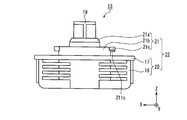
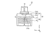
図1は、本実施形態の栄養剤用容器の一例を示した正面図であり。図2Aは、図1に示された栄養剤用容器を構成する本実施形態の医療用ポートの一例を示した拡大斜視図であり、図2Bは、図2Aに示された医療用ポートの部分拡大図であり、図2Cは、図2Aに示された医療用ポートの平面図、図2Dは、図2Aに示された医療用ポートの底面図、図2Eは、図2Aに示された医療用ポートの側面図、図2Fは、図2Aに示された医療用ポートの他の側面図、図2Gは、図2Aに示された医療用ポートの断面図、図2Hは、図2Aに示された医療用ポートの他の断面図である。
以下、説明の便宜のため、図2A等に示したように、連通部材19の中心軸19nと平行な方向をZ軸、Z軸と直交し且つ天面部17の長軸方向をX軸、Z軸及びX軸と直交する方向をY軸とする。Z軸方向を「上下方向」と呼び、Z軸の矢印の側(即ち図2の紙面上側)を「上側」又は「先端側」と呼び、その反対側(即ち図2の紙面下側)を「下側」又は「基端側」と呼ぶ。
図1に示されるように、栄養剤用容器10は、平袋状の可撓性袋状部材29を含む容器本体部11と、容器本体部11内に充填された栄養剤を含む液状物(図示せず)と、容器本体部11の下端に固定された医療用ポート13とを備える。可撓性袋状部材29の上部には、栄養剤用容器10をスタンド等に吊り下げるための吊り下げ部28が設けられている。
容器本体部11は、例えば、2枚の軟質樹脂シート16a,16bを重ね、それらの外周縁を相互にヒートシール(熱接着)することにより形成される。図1の参照符号2は、2枚の軟質樹脂シート16a,16bのヒートシール領域(図1においてドットが付された部分)を示す。医療用ポート13は、軟質樹脂シート16a,16b間に挟まれて容器本体部11に固定されている。医療用ポート13は、例えば、軟質樹脂シート16a,16b間に配置された状態で軟質樹脂シート16a,16bのヒートシール領域2をヒートシールすることで、軟質樹脂シート16a,16bに一体化させることができる。
軟質樹脂シート16a,16bとしては、特に制限はないが、例えば医療用軟質容器に用いられる、従来より公知の軟質樹脂シートを使用できる。具体的には、例えば、塩化ビニル樹脂、ポリエチレン、エチレン-酢酸ビニル共重合体、ポリエステル、ポリブタジエン、ポリプロピレン、ポリアミド、エチレン-メタクリレート共重合体等からなる単層シート、又は上記単層シートが2層以上積層された積層シートが挙げられる。積層シートの具体的層構成としては、例えば、ナイロン/ポリエチレン、ナイロン/ポリプロピレン、ポリエチレンテレフタレート/ポリエチレン、ポリエチレンテレフタレート/ポリプロピレン、ポリプロピレン/ポリエチレン、ナイロン/ポリプロピレン/ポリエチレン等が挙げられる。あるいは、グレード(例えば成膜方法、機械的特性、または組成など)が異なる同種の樹脂を積層した積層シート(例えば、二軸延伸ポリプロピレン(OPP)/無延伸ポリプロピレン(CPP)等)であってもよい。ヒートシールされる側の表面は、易ヒートシール性を有する材料(例えばポリプロピレン)で構成されることが好ましい。軟質樹脂シート16a,16bの厚さは、特に限定はないが、例えば0.1~0.6mm程度である。軟質樹脂シート16a,16bは透光性(または半透明性)を有していると、可撓性袋状部材29内の液状物を外から視認することができるので好ましい。より好ましくは、軟質樹脂シート16a,16bは透明である。
可撓性袋状部材29内に充填された液状物が医療用ポート13から流出するに伴い、可撓性袋状部材29内の圧力は低くなるが、可撓性袋状部材29が、軟質樹脂シート等の軟質材で形成されている場合は、液状物の流出に伴い可撓性袋状部材29が変形し、液状物の流出は継続する。
図2A~図2Hに示されるように、医療用ポート13は、ポート本体部22と、ポート本体部22に連結されたブリッジ19a(図2B等参照)と、ブリッジ19aを介してポート本体部22に連結された連通部材19と、薄膜16(図2D,図2G,及び図2H参照)とを含む。ポート本体部22と、ブリッジ19aと、連通部材19とは、射出成形法等により一体成形できる。
ブリッジ19aは、連通部材19を押圧により薄膜16側に押し込むと、いずれかの箇所がちぎれるものであり、その厚さ、幅等については、その材料に応じて適宜決定される。
ポート本体部22は、基部20と接続部21とを含む。基部20は、XY面と平行な面を含む天面部17と、天面部17から下側に向ってZ軸と平行に立設され、容器本体部11(図1参照)の内面に固定される側壁部18とを備える。そのため、ポート本体部22の天面部17よりも下側には、側壁部18によって囲われた、例えば、円筒状の空間20aが存在する。空間20aは、医療用ポート13が容器本体部11に固定された状態では、容器本体部11内と連通する。図1に示されるように、医療用ポート13が容器本体部11(図1参照)に固定された状態では、接続部21の全体は、容器本体部11の外に配置され、基部20の少なくとも1部は、容器本体部11内に配置される。
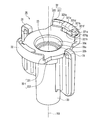
図2Aに示されるように、接続部21は、天面部17よりも上側に突出した管状部21aと、管状部21aの周囲に形成された接続部用基部21bと、1対の爪部21cとを含む。管状部21aは、上下方向に貫通する貫通孔21d(図2G、図2H参照)を有している。貫通孔21dは、貫通孔21dの下側の空間20aと連通している。図2Bに示されるように、ポート本体部の管状部21aには、ブリッジ19aを介して連通部材19が連結されており、貫通孔21d(図2G、図2H参照)内に連通部材19の一部が挿入されている。故に、連通部材19の他の一部は管状部21aの上側に突出している。
1対の爪部21cは、接続部用基部21bの外周面から外方向(XY面と平行な方向)に突出している。1対の爪部21cは、後述する送液回路27(図5等参照)のコネクタ25との接続状態を保持可能とする接続部として機能する。図2Cに示されるように、医療用ポート13を、Z方向と平行な方向に沿って見たとき、1対の爪部21cは、例えば、天面部17の長軸(X軸)上に配置されている。図2E及び図2Fに示されるように、1対の爪部21cは、その天面部17と向かい合う面に、後述する送液回路27(図5等参照)のコネクタ25のロック凹部321g(図7A参照)に嵌合し得るロック突起211cを含んでいる。
図2Dに示されるように、Z軸方向に沿って見た、空間20aを取り囲む側壁部18の外周面18aの形状は、略ひし形であり、当該略ひし形のX方向両端部における幅がそれぞれ先端に向かって漸次狭くなっている。そのため、側壁部18を、容器本体部11を構成する2枚の軟質樹脂シート材16a,16b(図1参照)で挟んで、ヒートシールにより医療用ポート13を軟質樹脂シート16a,16bに固定する際に、軟質樹脂シート16a,16b同士が密着する箇所と、軟質樹脂シート16a,16bと側壁部18とが密着する箇所との境目において、シール不良が起こることが抑制され、好ましい。
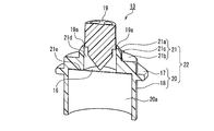
図2G及び図2Hに示されるように、接続部21の下面21e(接続部21の空間20aに面する面)には、貫通孔21dと空間20aとの間の液状物の流通を遮る薄膜16が取り付けられている。そのため、図1に示されるように、栄養剤用容器10を、医療用ポート13が下になるように向けても、栄養剤用容器10内の液状物は、栄養剤用容器10から漏れ出ない。薄膜16は、管状部21aの基端側端面に貼り付けられているので、貫通孔21dの延長線上に配置されていると言える。
薄膜16の材料としては、例えば、アルミ箔、紙とアルミ箔とからなる積層膜、容器用本体部11に含まれる樹脂と同じ樹脂を含む樹脂膜等が挙げられる。上記樹脂膜は、単層膜、複数層からなる積層膜のいずれであってもよい。中でも、熱溶着による薄膜16のポート本体部22に対する高い接着性を確保する観点から、ポート本体部22に接する面にポート本体部22に含まれる樹脂と同じ樹脂を含む樹脂膜が好ましい。薄膜16は、透明、半透明、不透明の何れであってもよいが、図2Dにおいては、理解の容易化のために、薄膜16にドットを付している(図11D,図16Dについても同様。)
薄膜16のポート本体部22への接着方法は、薄膜16の材料及びポート本体部22の材料等に応じて適宜選択される。
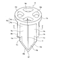
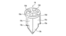
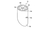
図3Aは、医療用ポートを構成するブリッジ19a及び連通部材19を説明する斜視図であり、図3Bは、図3Aに示した連通部材19のA-A'断面図である。連通部材19は、薄膜16(図2G参照)側とは反対側の端部において、平面形状が円形の板状部19eを含み、板状部19eには複数の貫通孔19dが形成されている。
また、連通部材19は、板状部19eよりも薄膜側において、薄膜側の空間を複数に区画する複数の隔壁19cを有している。隔壁19cは、各孔19dの延長方向における空間を相互に隔てるように配置されている。故に、送液回路27(図4等参照)のコネクタ25を医療用ポート13に接続するために、コネクタ25で連通部材19を薄膜側に押し込んで、穿刺部19bにより薄膜16を突き破った際には、複数の隔壁19cを有することにより形成され、ポート本体部22(基部20)の空間20aに対して開いた複数の空間19g及び複数の貫通孔19d(図3B参照)が、容器本体部11に充填された液状物を栄養剤用容器外へ(矢印Xの方向へ(図3A参照))流出させ得る複数の流路19pとして機能する。図3A及び図3Bに示した連通部材19は、4つの隔壁19cを有し、故に4つの流路19pを有する。4つの隔壁19cは周方向に沿って等角度で配置されおり、かつ、相互に一体化されているので、図4Bに示されるように、複数の隔壁19cからなる区画体の断面形状は略十字である。
連通部材19は、その軸方向(Z軸方向)両端のうちの薄膜16側に穿刺部19bを有する。穿刺部19bはその先端が、薄膜16を突き破り可能な程度に尖っている。図3Aに示した例では、複数の隔壁19cが、各々、連通部材19の薄膜側の先端に向かって傾斜した傾斜面19mを有しており、各傾斜面19mが連通部材19の薄膜側の先端19fに集束して、薄膜16を突き破り可能とする穿刺部19bを形成している。
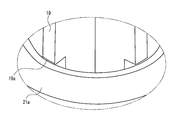
図3Aに示されるように、連通部材19は、穿刺部19bよりも薄膜側先端19fから離れたいずれかの箇所において、穿刺部19bよりも外方向(径方向)に出っ張った部分19h、換言すると、穿刺部19bよりも連通部材19の軸方向と直交する方向に出っ張った部分19hを有していると好ましい。穿刺部19bにより薄膜16を破った後、当該部分19hが、薄膜16の破られていない部分に接して、連通部材19が容器本体部11内に落下することが防止される。図3Aに示した例では、部分19hの薄膜16(図2G等参照)と向かい合う面19jが、薄膜16の破られていない部分に接して連通部材19が容器本体部11内に落下することが防止される。
ブリッジ19aは、隔壁19cから外方(例えば、連通部材19の軸方向と直交する方向)に突出するように設けられている。ブリッジ19aの数、形状等については、ポート本体部22により連通部材19が安定的に支持され、かつ、連通部材19を薄膜16側へ押し込む際にはブリッジ19aを容易に破断可能である限り、特に制限はない。例えば、連通部材19がその中心軸19n(図2A参照)を中心に放射状に配置された複数の隔壁19cを備え、複数の隔壁19cの管状部21aの内周面と向かい合う面が周方向に沿って配置されている場合、ブリッジ19aは、複数の隔壁19cのうちの、1つおきの隔壁19cから外方向(径方向)に延びるように設けられてもよい。例えば、図3A及び図3Bに示された連通部材19では、隔壁19cの数が4つであるので、相互に180度離れた2つの隔壁19cのみにブリッジ19aを設ける。
図4に、医療用ポート13の接続部21及び連通部材19に対して、コネクタ25とコネクタ25に接続された可撓性チューブ26とを含む送液回路27が接続される直前の様子を示し、図5に、接続部21及び連通部材19に対して送液回路27が接続される途中、図6A及び図6Bに、接続部21及び連通部材19に対して送液回路27が接続される途中であって、薄膜16が破られた状態を示している。
図4~図6Bに示されるように、接続部21及び連通部材19は、図7A~図7Eを用いて後述するコネクタ25を含む送液回路27に接続される構造となっている。そのため、専ら、先端が鋭利な接続針を接続対象に突き刺すことによって液状物を体内に送る静脈栄養療法用の送液回路が、誤って、経腸栄養療法に使用される栄養剤用容器10(図1参照)に接続されるという誤接続の問題が解決される。さらに、図3A~図3Gに示されるように、連通部材19の穿刺部19b側とは反対側の端面において、複数の貫通孔19dが形成されており、先端が鋭利な接続針が貫通孔内に挿入され難い形態となっているので、上記誤接続をより確実に防止できる。
図4~図6Bに示されるように、コネクタ25内に管状部21aを圧入した後、コネクタ25をその軸を中心に回転させれば、後述するように医療用ポート13の爪部21cがコネクタ25の係合部に係合するので、コネクタ25は接続部21に固定され、コネクタ25の抜けが確実に防止される。また、爪部21cとコネクタ25の係合部とが係合した状態では、図6Bに示されるように、管状部21aの外周面212がコネクタ25の内面(大径部33a)と密着するので、コネクタ25と医療用ポート13とが、液漏れを生じさせることなく接続される。
なお、医療用ポート13とコネクタ25との接続状態の保持は、各種の公知の構造によって行われればよく、医療用ポート13の接続部である、ロック凸部211cを含む爪部21c(図2F等参照)と、コネクタ25のロック凹部321gを含む係合壁321d(図7A参照)との係合以外の方法により行われてもよい。
医療用ポート13の薄膜16以外の材料としては、特に制限はないが、軟質樹脂シート16a,16bの材料よりも硬い、例えば、ポリエチレン(PE)、ポリプロピレン(PP)、ポリアセタール(POM)、ポリエチレンテレフタレート(PET)、ポリカーボネート(PC)等が挙げられる。
次に、医療用ポート13に接続されるコネクタの一例について、図7A~図7Eを用いて説明する。
図7Aは、本発明の医療用ポートに接続されるコネクタ25の一例の概略構成を示した斜視図であり、図7Bは、図7Aに示したコネクタ25の平面図であり、図7Cは、図7Aに示したコネクタ25の底面図であり、図7Dは、図7Aに示したコネクタ25の側面図であり、図7Eは、図7Aに示したコネクタ25の他の側面図である。
図7A~図7Eに示されるように、メス型のコネクタ25は、挿入部33と、送液チューブ接続部30と、鍔部32と、把持部31とを含む。コネクタ25は、栄養剤用容器10(図1参照)の医療用ポート13に接続されることにより、容器本体部11内とコネクタ25に接続された可撓性チューブ26(図4~図6B等参照)の内腔とを連通可能とする。一点鎖線151は挿入部33及び送液チューブ接続部30の中心軸であり、中心軸151の方向を上下方向とし、図7Aの紙面上側(医療用ポートに接続される側)を「上側」、紙面下側を「下側」と呼ぶことにする。
コネクタ25は、全体として略筒形状を有し、その上端近傍の挿入部33は、医療用ポート13の管状部21aの最大外径と等しいか僅かに小さな内径を有する大径部33aを有し、大径部33aより下側に、連通部材19の板状部19e(図3A参照)の外径及び大径部33aの内径より小さな内径を有する小径部33bを有する。大径部33aの内径は、筒状部21aの最大外径と等しいか僅かに小さいので、コネクタ25の挿入部33に医療用ポート13の管状部21aを押し込んでコネクタ25と医療用ポート13とが接続された状態の時に、管状部21aの外周面212が大径部33aの内周面に密着する(図6B参照)。したがって、医療用ポート13とコネクタ25とを液状物の漏れを生ずることなく確実に接続できる。
そして、コネクタ25の挿入部33は、大径部33aと小径部33bとを有することにより、大径部33aと小径部33bとの間に段差面33cを有する。この段差面33cは、コネクタ25が医療用ポート13に接続されたときに、管状部21aの端面211a及び連通部材19の端面19kと接する(図6B参照)。
小径部33bよりも下側には、略円筒状の送液チューブ接続部30が設けられている。
大径部33aの周囲で且つこれより上側に、一対の鍔部32が形成されている。一対の鍔部32は中心軸151に対して対称である。鍔部32は、中心軸151を中心軸とする円筒面にほぼ沿った円弧状壁321と、中心軸151に垂直な方向に延びて円弧状壁321の下端と大径部33aの上端とを繋ぐ渡り部322とを有する。
図7A及び図7Bに示されるように、円弧状壁321は、中心軸151に対向する内周面の形状の相違により、通過領域321aと、係合領域321bと、非通過領域321cとを含む。図7Bに示されるように、通過領域321aの内周面は直径DF21の円筒面の一部であり、非通過領域321cの内周面は直径DF23(DF23<DF21)の円筒面の一部である。通過領域321aと非通過領域321cとの間の係合領域321bは、図7Aに示されるように、その上端に、通過領域321aの上端と非通過領域321cの上端とを繋ぐように周方向に延在する係合壁321dを備える。係合壁321dの中心軸151に対向する内周面は、直径DF22(DF22<DF21)の円筒面の一部である。係合領域321bは、係合壁321dを備えることによって、係合壁321dと渡り部322との間の領域が凹状に陥没している。すなわち、係合壁321dと渡り部322との間の領域は、係合壁321dよりも相対的に中心軸151から後退して、凹部321eを構成している。係合領域321bに対して周方向に隣接する非通過領域321cは、凹部321eに対して相対的に中心軸151方向に突出しており凸部321fを構成する。係合壁321dの非通過領域321c側端の下面(凹部321e側の面、渡り部322に面する面)には、凹状に窪んだロック凹部321gが形成されている。渡り部322のうちの係合壁321dと向かい合う部分には、渡り部322の厚み方向に貫通する貫通孔220(図7C参照)が形成されているが、貫通孔220は形成されていなくてもよい。
また、図7Aに示されるように、挿入部33の周囲に、挿入部33の外周面から外方向(中心軸151に直交する方向)に突出した、一対の把持部31が形成されている。医療用ポート13の爪部21c(図2A等参照)を鍔部32に係合させるために行われる回転操作の際に、この一対の把持部31を持って回転操作が行われる。
次に、コネクタ25の医療用ポート13への接続方法を説明する。
図4~図6Bに示されるように、コネクタ25の挿入部33内に連通部材19が挿入されるように、コネクタ25を医療用ポート13に装着しながら、連通部材19を薄膜側16側へ押し込み、ブリッジ19a(図2B等参照)を破断し、連通部材19の穿刺部19bで薄膜16を破る。すなわち、コネクタ25を医療用ポート13に接続するための操作によって連通部材19を容器本体部11(図1参照)側に押し込む。
次いで、把持部31を把持して、医療用ポート13に対してコネクタ25を中心軸の周りに回転させれば、コネクタ25の回転に伴い、ロック突起211c(図2F等参照)が、係合壁321dの渡り部322側の面321hに押さえつけられながら当該面321h上を摺動し、次いでロック凹部321g(図7A参照)に嵌合する。ロック突起211cとロック凹部321gとの嵌合により、コネクタ25が医療用ポート13に接続された状態を安定的に保持できる。
このように、栄養剤用容器10(図1参照)では、例えば、医療用ポート13の連通部材19をコネクタ25で容器本体部11側に押し込みながら、コネクタ25を医療用ポート13に接続するだけで、栄養剤用容器10内と送液回路27内とを連通させることができるので、液状物の供給が簡単な操作で衛生的に行える。
また、コネクタ25には、爪部21c(図2F等参照)が収納されるロック凹部321gに隣接して凸部321f(図7A参照)が設けられているので、医療用ポート13の爪部21cをロック凹部321g内に侵入させ、更に凸部321fに当接するまで移動させれば、爪部21cと係合壁321dとを確実に係合させることができる。
また、医療用ポート13の爪部21cがコネクタ25の凸部321fに当接することにより、医療用ポート13に対するコネクタ25の回転が規制されることが好ましい。これにより、医療用ポート13に対してコネクタ25を、回転が規制されるまで回転させるという簡単な操作により、爪部21cと係合壁321dとを確実に係合させることができる。
コネクタ25の、JIS-K7202に基づいて測定される硬度は、送液チューブ接続部30への可撓性を有する送液チューブ26の接続作業性の向上の観点から、R40~R140であると好ましく、R50~R100であるとより好ましい。
連通部材19の形態については、図3A及び図3Bに示されたものに限定されない。例えば、図3Cに示されるように、連通部材19は、板状部19eに3つの貫通孔19dを有し、板状部19eよりも薄膜側に3つの隔壁19cを有し、3つの流路を有するものであってもよい。図3Cに示された連通部材19においては、全ての隔壁19cにブリッジ19aが設けられており、複数のブリッジ19aは周方向に等間隔に配置されているが、ポート本体部22(図2等参照)により連通部材19が安定的に支持されるのであれば、少なくとも1つのブリッジ19aが設けられていればよい。
図3Dに示されるように、連通部材19は、板状部19eに2つの貫通孔19dを有し、板状部19eよりも薄膜側に1つの隔壁19cを有し、2つの流路を有するものであってもよい。図3Dに示された連通部材19においては、隔壁19cの管状部21aの内周面と向かい合う面にブリッジ19aが各々形成されている。すなわち、図3Dに示された連通部材19においては、1つの隔壁19cに1対のブリッジ19aが、連通部材19の中心軸に対して対称に設けられているが、ポート本体部(図2等参照)により連通部材19が安定的に支持されるのであれば、少なくとも1つのブリッジ19aが設けられていればよい。
図3E~図3Gに示されるように、連通部材19は、略円筒状であり、貫通孔19dを2~4つ有することにより、その内腔が2~4つに分割され、2~4つの流路を有するものであってもよい。図3E~図3Gに示されるように、連通部材19が略円筒状であり、連通部材19の長手方向両端のうちの穿刺部19b側からその端面を平面視した場合の外形が例えば円形であると、連通部材19の穿刺により薄膜16に大きな孔を形成できる観点から好ましい。図3E~図3Gに示された連通部材19においても、ポート本体部(図2等参照)により連通部材19が安定的に支持されるのであれば、その外周面に、少なくとも1つのブリッジ19aが設けられていればよい。
(実施形態2)
次に、図8~図9Dを用いて、本発明の医療用ポートの他の一例、及び当該医療用ポートを用いた本発明の栄養剤用容器の他の一例について説明する。
次に、図8~図9Dを用いて、本発明の医療用ポートの他の一例、及び当該医療用ポートを用いた本発明の栄養剤用容器の他の一例について説明する。
図8は、本実施形態の栄養剤用容器の一例を示した部分斜視図である。図8に示されるように、本実施形態の医療用ポート及び栄養剤用容器は、医療用ポート13が、連通部材19を保護するための保護カバー40をさらに含むこと以外は実施形態1の医療用ポート及び栄養剤用容器と同じ構成をしており、同一部材には同じ部材番号を付してその説明を省略する。
本実施形態では、保護カバー40によって連通部材19が保護されているので、希望しない時に連通部材19に外力が加わることが防止される。故に、希望しない時に連通部材19に外力が加わり、連通部材19が容器本体部11側(ポート本体部22の開口部22a側)に押し込まれ、容器本体部11側に押し込まれた連通部材19により薄膜16(図2G等参照)が突き破られることを防止できる。
保護カバー40は、図9A~図9Dに示すように、連通部材19を天面部17(図2A参照)の外面側から覆うカバー本体41と医療用ポート13の爪部21c(図2A参照)と係合可能な係合壁421dを係合部として含む1対の鍔部42とを含む。保護カバー40の鍔部42は、上記コネクタ25の鍔部と同一構造をしている。
保護カバー40を、カバー本体41内に連通部材19及び接続部用基部21b(図2A参照)が収まるように被せ、保護カバー40を回転させて、医療用ポート13の爪部21cのロック突部211c(図2F等参照)を、係合壁421dの非通過領域421c側端の下面(凹部418側の面)に形成されたロック凹部421gに嵌合させれば、保護カバー40が医療用ポート13に装着された状態を安定的に保持できる。
本実施形態においても、実施形態1と同様に、静脈栄養療法に用いられる送液回路が誤って接続されるという誤接続の問題を解決できるだけでなく、栄養剤等の液状物の供給が簡単な操作で、衛生的に行える。保護カバー40を医療用ポート13から取り外し、例えば、コネクタ25を介して連通部材19に薄膜16側に押し込む力を付与して薄膜16を破り、医療用ポート13に送液回路27を接続するだけで(図5~図7B等参照)、患者への液状物の供給が可能となる。
(実施形態3)
実施形態3では、図10~図14を用いて、本発明の医療用ポートの他の一例、及び当該医療用ポートを用いた本発明の栄養剤用容器の他の一例について説明する。
実施形態3では、図10~図14を用いて、本発明の医療用ポートの他の一例、及び当該医療用ポートを用いた本発明の栄養剤用容器の他の一例について説明する。
図10は、本実施形態の栄養剤用容器の一例を示した正面図である。図11Aは、図10に示された栄養剤用容器を構成する本実施形態の医療用ポートの一例を示した拡大斜視図であり、図11Bは、図11Aに示された医療用ポート43の部分拡大図であり、図11Cは、図11Aに示された医療用ポート43の平面図、図11Dは、図11Aに示された医療用ポート43の底面図、図11Eは、図11Aに示された医療用ポート43の側面図、図11Fは、図11Aに示された医療用ポート43の他の側面図である。図12は、図11Aに示した医療用ポート43のブリッジ及び連通部材を説明する斜視図である。図10~図12に示されるように、本実施形態の医療用ポート及び栄養剤用容器は、薄膜16の取り付け位置と、連通部材39の形状、ブリッジ39aの形状、及び接続部用基部211bの形状が異なること以外は実施形態1の医療用ポート及び栄養剤用容器と同じ構成をしており、同一部材には同じ部材番号を付してその説明を省略する。
図13に示されるように、側壁部18の下面18bに薄膜16が貼り付けされている。よって、栄養剤用容器10(図10参照)では、管状部21aの貫通孔21d及び側壁部18によって囲われた空間20aと、容器本体部11(図10参照)内との間の液状物の流通が、薄膜16によって遮られている。そのため、図10に示されるように、栄養剤用容器10を、医療用ポート53が下になるように向けても、栄養剤用容器10内の液状物は、栄養剤用容器10から漏れ出ない。薄膜16は、ポート本体部22の開口部22a(図10参照)を塞ぐように、側壁部18の下面に取り付けられているので、貫通孔21dの延長線上に配置されていると言える。
実施形態1の医療用ポート13では、接続部用基部211b(図2A等参照)が管状部21aと一体化しており、例えば、接続部用基部211bと管状部21aとの間に両者を別ける稜線等の境界線は無い。しかし、本実施形態の医療用ポート43では、図11A等に示されるように、接続部用基部211bは、天面部17から上側に突出し、且つ、管状部21aから離隔して設けられているので、管状部21aと接続部用基部211bとの間に、溝部211dが存在する。そのため、本実施形態の医療用ポート43は、実施形態1の医療用ポート13よりも、成形時にヒケ等が生じ難く、製造が容易であるため、好ましい。
図13に示されるように、連通部材39は、薄膜16(図13参照)側とは反対側に筒状部39eを含む。図11B、図11C及び図12に示されるように、筒状部39eは、連通部材39を薄膜側とは反対側の端面側から平面視した場合に見える円周の一部が切り欠かれるように形成され、連通部材39の軸方向に沿って形成された切欠き部39hを有している。筒状部39eの外側面は、管状部21aの内径よりも僅かに小さい径の円筒面の一部である。また、図13及び図12に示されるように、連通部材39は、その軸方向両端のうちの薄膜16側に穿刺部39bを有する。穿刺部39bはその先端が、薄膜を突き破り可能な程度に尖っている。図12に示されるように、連通部材39では、薄膜側の先端に向かって傾斜した1対の傾斜面39mを有し、各傾斜面39mが、連通部材39の薄膜側の先端39fに集束して、薄膜16を突き破り可能とする穿刺部39bを形成している。穿刺部39bによって薄膜16が突き破られた際には、連通部材39の内腔39jは、容器本体部11(図10参照)に充填された液状物を栄養剤用容器外へ(矢印Aの方向へ)流出させ得る流路として機能する。
ポート本体部22と、ブリッジ39aと、連通部材39とは、射出成形法等により一体成形できる。図11Bに示されるように、ブリッジ39aは、切り欠き部39hを通って筒状部39eの内側と外側とに跨っており、連通部材39の内周面39kと接続部21の管状部21aとを連結している。ブリッジ39aは、連通部材39に対して押圧により薄膜16(図13参照)側に押し込む力が付与されると、塑性変形し、押圧力を受けなくなっても元の形にもどらないものである。ブリッジ39aの厚さ、幅等については、連通部材39を薄膜16(図13参照)側に押し込んだ際に塑性変形が可能であるように、その材料に応じて適宜決定される。
ブリッジ39aの長さは、連通部材39の穿刺部39bにより薄膜16(図13参照)を突き破ることができる程度に、連通部材39を薄膜16側へ移動させることを可能とする長さであることを要する。そのようなブリッジ39aの長さを確保する観点から、図11B及び図11Cに示されるように、連通部材39を薄膜側とは反対側の端面側から平面視した場合に見えるブリッジ39aの形状は、例えば、S字状であると好ましい。
また、図12に示されるように、連通部材39の形状が、その長手方向両端のうちの一方の端部が穿刺部39bを含み薄膜16を突き破り可能な程度に尖った円筒状等の筒状であり、切り欠き部39hが、連通部材39の長手方向全長に渡って形成されている場合、連通部材39の穿刺により薄膜16により大きな孔を形成可能とする観点から、切り欠き部39hの幅(切り欠き部39hの長手方向と直交する方向の長さ)は、ブリッジ39aの切り欠き部39内に存在する部分の幅よりも僅かに大きい程度であると好ましい。
図13に、医療用ポート43の接続部21及び連通部材39に対して、コネクタ25(図4~6A参照)とコネクタ25に接続された可撓性チューブ26(図4参照)とを含む送液回路27(図4~6A参照)が接続される前の様子を示し、図14に、連通部材39によって薄膜16が破られた状態を示している。尚、図13~図14において、図4~図6Aに示した送液回路27は省略している。
本実施形態においても、接続部21及び連通部材39は、図7A~図7Eを用いて説明したコネクタ25を含む送液回路27に接続される構造となっている。そのため、専ら、先端が鋭利な接続針を接続対象に突き刺すことによって液状物を体内に送る静脈栄養療法用の送液回路が、誤って、経腸栄養療法に使用される栄養剤用容器10(図10等参照)に接続されるという誤接続の問題が解決される。さらに、図11B等に示されるように、連通部材39内には、連通部材39内の内腔(流路)39jを横切るようにブリッジ39aが配置されており、換言すると、ブリッジ39aが、流路を跨ぐように、連通部材39とポート本体部22の管状部21a(図11A及び図11B等参照)とを連結している。そのため、先端が鋭利な接続針が連通部材39内に挿入され難い形態となっており、上記誤接続をより確実に防止できる。
本実施形態においても、例えば、コネクタ25を介して連通部材39に薄膜16(図13参照)側へ押し込む力を付与して、ブリッジ39aを塑性変形し、薄膜16を破り、医療用ポート43に送液回路27(図5参照)を接続するだけで、患者への液状物の供給が可能となる。よって、本実施形態においても、実施形態1と同様に、静脈栄養療法に用いられる送液回路が誤って接続されるという誤接続の問題を解決できるだけでなく、栄養剤等の液状物の供給が簡単な操作で、衛生的に行える。
尚、ブリッジ39aは、連通部材39に対して押圧により薄膜16側に押し込む力を加えると、塑性変形し、押圧力を受けなくなっても元の形にもどらないものに限定されず、破断するものであってもよいし、弾性変形するものであり、押圧力を受けなくなった場合に元の形にもどるものでもよい。また、ブリッジ39aは、ポート本体部22と連通部材39とが繋がったまま薄膜16を破ることができる場合は、連通部材39が容器本体部11(図10参照)内に落下して液状物に連通部材39が浮遊することが確実に防止でき好ましいが、本実施形態において、ブリッジ39aは破断するものであってもよい。
また、本実施形態の医療用ポート及び栄養剤用容器は、実施形態2で説明した保護カバーを備えていてもよい。
(実施形態4)
実施形態4では、図15~図18Dを用いて、本発明の医療用ポートの他の一例、及び当該医療用ポートを用いた本発明の栄養剤用容器の他の一例について説明する。
実施形態4では、図15~図18Dを用いて、本発明の医療用ポートの他の一例、及び当該医療用ポートを用いた本発明の栄養剤用容器の他の一例について説明する。
図15は、本実施形態の栄養剤用容器の一例を示した正面図である。図16Aは、図15に示された栄養剤用容器を構成する本実施形態の医療用ポートの一例を示した拡大斜視図であり、図16Bは、図16Aに示された医療用ポート53の部分拡大図であり、図16Cは、図16Aに示された医療用ポート53の平面図、図16Dは、図16Aに示された医療用ポート53の底面図、図16Eは、図16Aに示された医療用ポート53の側面図、図16Fは、図16Aに示された医療用ポート53の他の側面図、図17Aは、図16Aに示された医療用ポート53のB-B’断面図であり、図17Bは、図16Aに示された医療用ポート53のC-C’拡大断面図である。図15~図17Bに示されるように、本実施形態の医療用ポート及び栄養剤用容器は、薄膜16の取り付け位置、連通部材49の形状、及びブリッジ49aの形状が異なること以外は実施形態2の医療用ポート及び栄養剤用容器と同じ構成をしており、同一部材には同じ部材番号を付してその説明を省略する。
図16D及び図17Aに示されるように、側壁部18の下面18bに薄膜16が貼り付けされている。よって、栄養剤用容器10(図15参照)では、管状部21aの貫通孔21d及び側壁部18によって囲われた空間20aと、容器本体部11(図15参照)内との間の液状物の流通が、薄膜16によって遮られている。そのため、図15に示されるように、栄養剤用容器10を、医療用ポート53が下になるように向けても、栄養剤用容器10内の液状物は、栄養剤用容器10から漏れ出ない。薄膜16は、ポート本体部22の開口部22a(図15参照)を塞ぐように、側壁部18の下面18b(図17A参照)に取り付けられているので、貫通孔21dの延長線上に配置されていると言える。
図16A及び図16Bに示されるように、連通部材49は、薄膜16(図17A等参照)側の反対側に配置された筒状部49eを含む。筒状部49eは、互いに向かい合うように配置され筒状部49eの中心軸に対して相互に対称に配置された1対の平板状部491eと、これらを連結する1対の湾曲板状部492eとを含む。各湾曲板状部492eの外側面は、管状部21aの内径よりも僅かに小さい径の円筒面の一部であるが、平板状部491eの外側面は、当該円筒面よりも相対的に管状部21aから離れる方向に後退しており、凹部493eを構成している。
図17A及び図17Bに示されるように、連通部材49は、筒状部49eよりも薄膜側に、穿刺部49bを含み、管状部21a内の空間を複数に分割する隔壁49cを含んでいる。隔壁49cの薄膜側端部の幅が先端に向かって徐々に狭くなることにより、薄膜16を突き破り可能な程度に尖った穿刺部49bを形成している。図17Bに示されるように、隔壁49cは、湾曲板状部492eの下端に連結され、筒状部49eに一体化されているので、筒状部49eが薄膜16側に押し込まれると、隔壁49cも薄膜16側に押し込まれる。隔壁49cの主面は、1対の平板状部491eの主面と平行である。隔壁49cの大部分は、平板状部491eの各下端と管状部21aとを連結する1対のブリッジ49aよりも下方(薄膜16に近い側)に配置されているが、連通部材49を薄膜16側とは反対側の端面側から平面視した場合、隔壁49cは、1対のブリッジ49aの間に配置されているように見える(図16C参照)。
図18Aに、医療用ポート53の接続部及び連通部材49に対して、コネクタ25とコネクタ25に接続された可撓性チューブ26とを含む送液回路27(図4~図6A参照)が接続される前の様子を示し、図18B~図18Dに、連通部材49が薄膜16側に押し込まれる途中の様子を示している。尚、図18A~図18Dにおいて、図4~図6Aに示した送液回路27は省略している。
ポート本体部の管状部21aとブリッジ49aとの連結部位(第1連結部位)51の厚みT1は、ブリッジ49aのうちの当該連結部位51の近傍部分の厚みよりも薄い。ブリッジ49aと連通部材49の筒状部49eとの連結部位(第2連結部位)52の厚みT2は、ブリッジ49aのうちの当該連結部位52の近傍部分の厚みよりも薄い。また、ブリッジ49aは、例えばその中央部に厚みがT3の肉薄部54を含んでいる。そのため、コネクタ25(図4等参照)を介して連通部材49に対して押圧により薄膜16側に押し込む力を加えると、図18B~図18Dに示されるように、第1連結部位51から第2連結部位52までのブリッジ49aを含む部分Z(図18B~図18Dにおいてドットが付された部分)のうちの、第1連結部位51、第2連結部位52及び肉薄部54を含む3つの肉薄部が各々折れ曲がり変形し、連通部材49は薄膜16側に押し込まれ、連通部材49の穿刺部49bにより薄膜16が突き破られる。第1連結部位51の厚みT1、第2連結部位52の厚みT2、及び肉薄部54の厚みT3及びブリッジ49aの各部位の厚み等については、その材料に応じて適宜決定される。
図18Dに示された連通部材49がさらに薄膜16側に押し込まれ、爪部21c(図16A等参照)とコネクタ25の係合壁321d(係合部、図7A等参照)とが係合した状態では、連通部材49の薄膜16側の反対側の端面49fは、管状部21aの開口端面211aとほぼ面一になる。筒状部49eが薄膜16側に押し込まれ、管状部21a内に挿入された状態では、平板状部491eの外側面と、これに向う合う管状部21aの内面との間には隙間が形成されるが、当該隙間、即ち凹部493e(図16B参照)と管状部21aの内周面とによって囲われる空間内に、折れ曲がったブリッジ49aが収納される。
本実施形態においても、接続部21及び連通部材49は、図7A~図7Eを用いて説明したコネクタ25を含む送液回路27に接続される構造となっている。そのため、専ら、先端が鋭利な接続針を接続対象に突き刺すことによって液状物を体内に送る静脈栄養療法用の送液回路が、誤って、経腸栄養療法に使用される栄養剤用容器10(図15参照)に接続されるという誤接続の問題が解決される。
また、本実施形態においても、例えば、コネクタ25を介して連通部材49に薄膜16側に押し込む力を付与して、第1連結部位51から第2連結部位52までのブリッジ49aを含む部分Zを折り曲げ変形し、必要に応じて塑性変形し、薄膜16を破り、医療用ポート53に送液回路27(図4参照)を接続するだけで、患者への液状物の供給が可能となる。よって、本実施形態においても、実施形態1と同様に、静脈栄養療法に用いられる送液回路が誤って接続されるという誤接続の問題を解決できるだけでなく、栄養剤等の液状物の供給が簡単な操作で、衛生的に行える。
尚、図18A等を用いて説明した本実施形態の一例では、ブリッジ49aの肉薄部54は1つであり、第1連結部位51、第2連結部位52、及び肉薄部54が折れ曲がることで連通部材49の薄膜16側への押し込みが許容されているが、ブリッジは1個以上または複数の肉薄部を含んでいてよい。連通部材49に対して押圧により薄膜側に押し込む力を加えた際に、折れ曲がり変形することにより、連通部材49の薄膜側への移動及び連通部材49による薄膜の突き破りが許容されれば、連結部位51、52の形状及び肉薄部の数等について特に制限はないが、部分Zにおける肉薄部の数は、肉薄部の数が少ないことによりブリッジが破断したり、肉薄部の数が多すぎることにより折れ曲がり方が複雑になることを抑制する観点から、3つが好ましい。
また、本実施形態において、ブリッジ49aは、連通部材49に対して押圧により薄膜側に押し込む力を加えると折れ曲がり変形するものであり、ポート本体部22と連通部材49とが繋がったまま薄膜16を破ることができるので、連通部材49が容器本体部11(図15参照)内に落下して液状物に連通部材49が浮遊することが確実に防止でき好ましいが、本実施形態において、ブリッジ49aは破断するものであってもよい。
また、本実施形態の医療用ポート及び栄養剤用容器は、実施形態2で説明した保護カバーを備えていてもよい。
尚、図1、図8、図10、図15に示した栄養剤用容器10の容器本体部11内には、栄養剤等の液状物(図示せず)が充填されているが、図19に示されるように、栄養剤用容器10は、容器本体部11内に液状物が充填されていない空の容器であってもよい。図19に示されるように、栄養剤用容器10の容器本体部11は、開口部23を有し、開口部23を幅方向に横切って、開口部23を可逆的に開閉可能にするジップ23a(再開閉を自在とする係合部である。別名「チャックシール」とも言う。)を備える。開口部23の上方には、吊り下げ部(図示せず)が設けられていてもよい。
また、図5に示された送液回路27は、図示の便宜上、コネクタ25と可撓性チューブ26の一部のみを図示しているが、実施形態1~4の医療用ポート及び栄養剤用容器に接続され、または、栄養剤用容器とともに栄養剤供給セットを構成する送液回路は、可撓性チューブ26を押圧して可撓性チューブ26を流れる液状物の流量を調節するための流量調整器、点滴筒、患者に固定された経鼻チューブ等に接続されうるコネクタ、当該コネクタのカバー等、従来公知の経腸栄養療法に使用される送液回路が備える構成部品をさらに含んでいてもよい。
本発明では、経腸栄養療法に好適な、栄養剤用容器の医療用ポート、及びそれを用いた栄養剤用容器、並びに、当該栄養剤用容器を含む栄養剤供給セットを提供できる。
10 栄養剤用容器
11 容器本体部
13、43、53 医療用ポート
17 天面部
18 側壁部
19、39、49 連通部材
19a、39a、49a ブリッジ
19b、39b、49b 穿刺部
19c、49c 隔壁
19e 板状部
19p,39j 流路
20 基部
21 接続部
22 ポート本体部
21a 管状部
21b,211b 接続部用基部
21c 爪部(接続部)
21d 貫通孔
25 コネクタ
26 可撓性チューブ
27 送液回路
40 保護カバー
51 ポート本体部とブリッジとの連結部位(第1連結部位)
52 ブリッジと連通部材との連結部位(第2連結部位)
54 ブリッジの肉薄部
Z ポート本体部とブリッジとの連結部位からブリッジと連通部材との連結部位までのブリッジを含む部分
11 容器本体部
13、43、53 医療用ポート
17 天面部
18 側壁部
19、39、49 連通部材
19a、39a、49a ブリッジ
19b、39b、49b 穿刺部
19c、49c 隔壁
19e 板状部
19p,39j 流路
20 基部
21 接続部
22 ポート本体部
21a 管状部
21b,211b 接続部用基部
21c 爪部(接続部)
21d 貫通孔
25 コネクタ
26 可撓性チューブ
27 送液回路
40 保護カバー
51 ポート本体部とブリッジとの連結部位(第1連結部位)
52 ブリッジと連通部材との連結部位(第2連結部位)
54 ブリッジの肉薄部
Z ポート本体部とブリッジとの連結部位からブリッジと連通部材との連結部位までのブリッジを含む部分
Claims (11)
- 栄養剤用容器の容器本体部に固定され、前記容器本体部の内外を連通させ得る医療用ポートであって、
前記医療用ポートは、
貫通孔と、前記容器本体部へ固定される側壁部と、コネクタとの接続状態を保持可能とする接続部と、を含むポート本体部と、
前記ポート本体部に取り付けられ、前記医療用ポートが前記容器本体部に固定された状態で前記容器本体部内の前記貫通孔の延長線上に配置され、前記容器本体部内の液状物の前記栄養剤用容器外への流出を遮る薄膜と、
前記ポート本体部に連結され、破断または変形可能なブリッジと、
その一部が前記貫通孔内に挿入され、且つ、前記ポート本体部に前記ブリッジを介して連結された、連通部材とを含み、
前記連通部材は、
前記連通部材が前記容器本体部側に押し込まれて前記ブリッジが破断または変形することにより前記薄膜を突き破り可能とする穿刺部と、
前記薄膜が突き破られた状態で前記容器本体部内の前記液状物を前記栄養剤用容器外へ流出させ得る流路とを含む、医療用ポート。 - 前記連通部材は、複数の前記流路を含み、前記薄膜側とは反対側の端面において各流路の一部を構成する孔が形成されている請求項1に記載の医療用ポート。
- 前記連通部材は、複数の前記流路を含み、前記薄膜側とは反対側の端部に板状部を含み、前記板状部に各流路の一部を構成する孔が形成されている請求項1に記載の医療用ポート。
- 前記連通部材は、前記板状部よりも前記薄膜側に配置され、各孔の延長方向における空間を相互に隔てるように配置された隔壁を含む請求項3に記載の医療用ポート。
- 前記連通部材の、前記穿刺部よりも前記薄膜側先端からより離れた箇所の一部が、前記穿刺部よりも前記連通部材の軸方向と直交する方向に出っ張っている請求項1~4のいずれかの項に記載の医療用ポート。
- 前記ブリッジが、前記流路を跨ぐように、前記連通部材と前記ポート本体部とを連結している請求項1に記載の医療用ポート。
- 前記ポート本体部と前記ブリッジとの連結部位(第1連結部位)から、前記ブリッジと前記連通部材との連結部位(第2連結部位)までの、前記ブリッジを含む部分が折れ曲がり変形することにより、前記連通部材を前記容器本体部側に押し込み可能とする請求項1に記載の医療用ポート。
- 前記第1連結部位から前記第2連結部位までの前記ブリッジを含む前記部分が、3つの肉薄部を含み、当該3つの肉薄部が折れ曲がり変形することにより、前記連通部材を前記容器本体部側に押し込み可能とする請求項7に記載の医療用ポート。
- 前記連通部材を覆い、前記接続部と係合可能な係合部を備えた保護カバーをさらに備えた請求項1~8のいずれかの項に記載の医療用ポート。
- 可撓性袋状部材を含む容器本体部と、
前記容器本体部に固定された請求項1~9のいずれかの項に記載の医療用ポートと、を含む栄養剤用容器。 - 請求項10に記載の栄養剤用容器と、
前記医療用ポートの前記接続部と係合可能な係合部を有するコネクタと、前記コネクタに接続された送液チューブとを含む送液回路とを含む、栄養剤供給セット。
Priority Applications (2)
| Application Number | Priority Date | Filing Date | Title |
|---|---|---|---|
| JP2013508648A JP5920339B2 (ja) | 2011-04-04 | 2011-04-04 | 医療用ポート、及びそれを用いた栄養剤用容器並びに栄養剤供給セット |
| PCT/JP2011/058534 WO2012137286A1 (ja) | 2011-04-04 | 2011-04-04 | 医療用ポート、及びそれを用いた栄養剤用容器並びに栄養剤供給セット |
Applications Claiming Priority (1)
| Application Number | Priority Date | Filing Date | Title |
|---|---|---|---|
| PCT/JP2011/058534 WO2012137286A1 (ja) | 2011-04-04 | 2011-04-04 | 医療用ポート、及びそれを用いた栄養剤用容器並びに栄養剤供給セット |
Publications (1)
| Publication Number | Publication Date |
|---|---|
| WO2012137286A1 true WO2012137286A1 (ja) | 2012-10-11 |
Family
ID=46968727
Family Applications (1)
| Application Number | Title | Priority Date | Filing Date |
|---|---|---|---|
| PCT/JP2011/058534 Ceased WO2012137286A1 (ja) | 2011-04-04 | 2011-04-04 | 医療用ポート、及びそれを用いた栄養剤用容器並びに栄養剤供給セット |
Country Status (2)
| Country | Link |
|---|---|
| JP (1) | JP5920339B2 (ja) |
| WO (1) | WO2012137286A1 (ja) |
Cited By (4)
| Publication number | Priority date | Publication date | Assignee | Title |
|---|---|---|---|---|
| CN109178640A (zh) * | 2018-11-15 | 2019-01-11 | 深圳市道中创新科技有限公司 | 带料包的容器 |
| US10548811B2 (en) | 2017-01-09 | 2020-02-04 | R. Scott Turner | Valve for fluid flow assembly |
| JP2021079599A (ja) * | 2019-11-18 | 2021-05-27 | 株式会社ミマキエンジニアリング | コネクターおよびインクジェットプリンター |
| US11674614B2 (en) | 2020-10-09 | 2023-06-13 | Icu Medical, Inc. | Fluid transfer device and method of use for same |
Citations (3)
| Publication number | Priority date | Publication date | Assignee | Title |
|---|---|---|---|---|
| JP2003523227A (ja) * | 1999-11-05 | 2003-08-05 | バイオドーム | 即時使用可能な接続デバイス |
| WO2010044353A1 (ja) * | 2008-10-16 | 2010-04-22 | 株式会社ジェイ・エム・エス | 注出口及び注出口付き液体収容体 |
| JP2010162165A (ja) * | 2009-01-15 | 2010-07-29 | Jms Co Ltd | コネクタ |
-
2011
- 2011-04-04 WO PCT/JP2011/058534 patent/WO2012137286A1/ja not_active Ceased
- 2011-04-04 JP JP2013508648A patent/JP5920339B2/ja active Active
Patent Citations (3)
| Publication number | Priority date | Publication date | Assignee | Title |
|---|---|---|---|---|
| JP2003523227A (ja) * | 1999-11-05 | 2003-08-05 | バイオドーム | 即時使用可能な接続デバイス |
| WO2010044353A1 (ja) * | 2008-10-16 | 2010-04-22 | 株式会社ジェイ・エム・エス | 注出口及び注出口付き液体収容体 |
| JP2010162165A (ja) * | 2009-01-15 | 2010-07-29 | Jms Co Ltd | コネクタ |
Cited By (6)
| Publication number | Priority date | Publication date | Assignee | Title |
|---|---|---|---|---|
| US10548811B2 (en) | 2017-01-09 | 2020-02-04 | R. Scott Turner | Valve for fluid flow assembly |
| CN109178640A (zh) * | 2018-11-15 | 2019-01-11 | 深圳市道中创新科技有限公司 | 带料包的容器 |
| JP2021079599A (ja) * | 2019-11-18 | 2021-05-27 | 株式会社ミマキエンジニアリング | コネクターおよびインクジェットプリンター |
| JP7308127B2 (ja) | 2019-11-18 | 2023-07-13 | 株式会社ミマキエンジニアリング | コネクターおよびインクジェットプリンター |
| US11674614B2 (en) | 2020-10-09 | 2023-06-13 | Icu Medical, Inc. | Fluid transfer device and method of use for same |
| US12345352B2 (en) | 2020-10-09 | 2025-07-01 | Icu Medical, Inc. | Fluid transfer device and method of use for same |
Also Published As
| Publication number | Publication date |
|---|---|
| JP5920339B2 (ja) | 2016-05-18 |
| JPWO2012137286A1 (ja) | 2014-07-28 |
Similar Documents
| Publication | Publication Date | Title |
|---|---|---|
| JP5672288B2 (ja) | メス型コネクタ、オス型コネクタ、接続構造、送液回路、および医療用容器 | |
| JP5915176B2 (ja) | キャップ、およびそれを用いた栄養剤用容器並びに栄養剤供給セット | |
| JP2006521124A (ja) | 医療用液体を収容するパック用のコネクタおよび医療用液体のパック | |
| JP5810913B2 (ja) | キャップ、およびそれを用いた栄養剤用容器 | |
| JP5920340B2 (ja) | 医療用ポート、およびそれを用いた栄養剤用容器並びに栄養剤供給セット | |
| KR101668500B1 (ko) | 주출구 및 주출구가 달린 액체 수용체 | |
| JP5920339B2 (ja) | 医療用ポート、及びそれを用いた栄養剤用容器並びに栄養剤供給セット | |
| CN106604758A (zh) | 半固态营养剂用连接器 | |
| JP4854940B2 (ja) | 医療用複室容器 | |
| JPWO2011046210A1 (ja) | キャップ、およびそれを用いた栄養剤用容器並びに栄養剤供給セット | |
| TWI587883B (zh) | Medical connector, container for nutrient container and nutrient supply container using the same | |
| JP6345391B2 (ja) | 雄コネクタ | |
| HK1172542B (en) | Cap, nutritional supplement container using same, and nutritional supplement supply set | |
| JP2007260252A (ja) | 医療用容器 | |
| HK1172541A (en) | Cap, and nutritional agent container and nutritional agent supply set that use same | |
| TW201240688A (en) | Medical connection head, nutrient container using the same and nutrient supply kit using the same | |
| HK1170657B (en) | Cap and nutritional supplement container using same | |
| HK1206586B (en) | Cap and nutritional supplement container using same |
Legal Events
| Date | Code | Title | Description |
|---|---|---|---|
| 121 | Ep: the epo has been informed by wipo that ep was designated in this application |
Ref document number: 11862864 Country of ref document: EP Kind code of ref document: A1 |
|
| ENP | Entry into the national phase |
Ref document number: 2013508648 Country of ref document: JP Kind code of ref document: A |
|
| NENP | Non-entry into the national phase |
Ref country code: DE |
|
| 122 | Ep: pct application non-entry in european phase |
Ref document number: 11862864 Country of ref document: EP Kind code of ref document: A1 |