WO2012133621A1 - Transmission - Google Patents
Transmission Download PDFInfo
- Publication number
- WO2012133621A1 WO2012133621A1 PCT/JP2012/058315 JP2012058315W WO2012133621A1 WO 2012133621 A1 WO2012133621 A1 WO 2012133621A1 JP 2012058315 W JP2012058315 W JP 2012058315W WO 2012133621 A1 WO2012133621 A1 WO 2012133621A1
- Authority
- WO
- WIPO (PCT)
- Prior art keywords
- gear
- shaft
- transmission
- parking
- axial
- Prior art date
Links
Images


Classifications
-
- F—MECHANICAL ENGINEERING; LIGHTING; HEATING; WEAPONS; BLASTING
- F16—ENGINEERING ELEMENTS AND UNITS; GENERAL MEASURES FOR PRODUCING AND MAINTAINING EFFECTIVE FUNCTIONING OF MACHINES OR INSTALLATIONS; THERMAL INSULATION IN GENERAL
- F16H—GEARING
- F16H3/00—Toothed gearings for conveying rotary motion with variable gear ratio or for reversing rotary motion
- F16H3/02—Toothed gearings for conveying rotary motion with variable gear ratio or for reversing rotary motion without gears having orbital motion
-
- F—MECHANICAL ENGINEERING; LIGHTING; HEATING; WEAPONS; BLASTING
- F16—ENGINEERING ELEMENTS AND UNITS; GENERAL MEASURES FOR PRODUCING AND MAINTAINING EFFECTIVE FUNCTIONING OF MACHINES OR INSTALLATIONS; THERMAL INSULATION IN GENERAL
- F16H—GEARING
- F16H63/00—Control outputs from the control unit to change-speed- or reversing-gearings for conveying rotary motion or to other devices than the final output mechanism
- F16H63/02—Final output mechanisms therefor; Actuating means for the final output mechanisms
- F16H63/30—Constructional features of the final output mechanisms
-
- B—PERFORMING OPERATIONS; TRANSPORTING
- B60—VEHICLES IN GENERAL
- B60T—VEHICLE BRAKE CONTROL SYSTEMS OR PARTS THEREOF; BRAKE CONTROL SYSTEMS OR PARTS THEREOF, IN GENERAL; ARRANGEMENT OF BRAKING ELEMENTS ON VEHICLES IN GENERAL; PORTABLE DEVICES FOR PREVENTING UNWANTED MOVEMENT OF VEHICLES; VEHICLE MODIFICATIONS TO FACILITATE COOLING OF BRAKES
- B60T1/00—Arrangements of braking elements, i.e. of those parts where braking effect occurs specially for vehicles
- B60T1/005—Arrangements of braking elements, i.e. of those parts where braking effect occurs specially for vehicles by locking of wheel or transmission rotation
-
- B—PERFORMING OPERATIONS; TRANSPORTING
- B60—VEHICLES IN GENERAL
- B60T—VEHICLE BRAKE CONTROL SYSTEMS OR PARTS THEREOF; BRAKE CONTROL SYSTEMS OR PARTS THEREOF, IN GENERAL; ARRANGEMENT OF BRAKING ELEMENTS ON VEHICLES IN GENERAL; PORTABLE DEVICES FOR PREVENTING UNWANTED MOVEMENT OF VEHICLES; VEHICLE MODIFICATIONS TO FACILITATE COOLING OF BRAKES
- B60T1/00—Arrangements of braking elements, i.e. of those parts where braking effect occurs specially for vehicles
- B60T1/02—Arrangements of braking elements, i.e. of those parts where braking effect occurs specially for vehicles acting by retarding wheels
- B60T1/06—Arrangements of braking elements, i.e. of those parts where braking effect occurs specially for vehicles acting by retarding wheels acting otherwise than on tread, e.g. employing rim, drum, disc, or transmission or on double wheels
- B60T1/062—Arrangements of braking elements, i.e. of those parts where braking effect occurs specially for vehicles acting by retarding wheels acting otherwise than on tread, e.g. employing rim, drum, disc, or transmission or on double wheels acting on transmission parts
-
- F—MECHANICAL ENGINEERING; LIGHTING; HEATING; WEAPONS; BLASTING
- F16—ENGINEERING ELEMENTS AND UNITS; GENERAL MEASURES FOR PRODUCING AND MAINTAINING EFFECTIVE FUNCTIONING OF MACHINES OR INSTALLATIONS; THERMAL INSULATION IN GENERAL
- F16H—GEARING
- F16H63/00—Control outputs from the control unit to change-speed- or reversing-gearings for conveying rotary motion or to other devices than the final output mechanism
- F16H63/02—Final output mechanisms therefor; Actuating means for the final output mechanisms
- F16H63/30—Constructional features of the final output mechanisms
- F16H63/34—Locking or disabling mechanisms
- F16H63/3416—Parking lock mechanisms or brakes in the transmission
-
- F—MECHANICAL ENGINEERING; LIGHTING; HEATING; WEAPONS; BLASTING
- F16—ENGINEERING ELEMENTS AND UNITS; GENERAL MEASURES FOR PRODUCING AND MAINTAINING EFFECTIVE FUNCTIONING OF MACHINES OR INSTALLATIONS; THERMAL INSULATION IN GENERAL
- F16H—GEARING
- F16H63/00—Control outputs from the control unit to change-speed- or reversing-gearings for conveying rotary motion or to other devices than the final output mechanism
- F16H63/02—Final output mechanisms therefor; Actuating means for the final output mechanisms
- F16H63/30—Constructional features of the final output mechanisms
- F16H2063/3079—Shift rod assembly, e.g. supporting, assembly or manufacturing of shift rails or rods; Special details thereof
-
- F—MECHANICAL ENGINEERING; LIGHTING; HEATING; WEAPONS; BLASTING
- F16—ENGINEERING ELEMENTS AND UNITS; GENERAL MEASURES FOR PRODUCING AND MAINTAINING EFFECTIVE FUNCTIONING OF MACHINES OR INSTALLATIONS; THERMAL INSULATION IN GENERAL
- F16H—GEARING
- F16H61/00—Control functions within control units of change-speed- or reversing-gearings for conveying rotary motion ; Control of exclusively fluid gearing, friction gearing, gearings with endless flexible members or other particular types of gearing
- F16H61/68—Control functions within control units of change-speed- or reversing-gearings for conveying rotary motion ; Control of exclusively fluid gearing, friction gearing, gearings with endless flexible members or other particular types of gearing specially adapted for stepped gearings
- F16H61/684—Control functions within control units of change-speed- or reversing-gearings for conveying rotary motion ; Control of exclusively fluid gearing, friction gearing, gearings with endless flexible members or other particular types of gearing specially adapted for stepped gearings without interruption of drive
- F16H61/688—Control functions within control units of change-speed- or reversing-gearings for conveying rotary motion ; Control of exclusively fluid gearing, friction gearing, gearings with endless flexible members or other particular types of gearing specially adapted for stepped gearings without interruption of drive with two inputs, e.g. selection of one of two torque-flow paths by clutches
-
- Y—GENERAL TAGGING OF NEW TECHNOLOGICAL DEVELOPMENTS; GENERAL TAGGING OF CROSS-SECTIONAL TECHNOLOGIES SPANNING OVER SEVERAL SECTIONS OF THE IPC; TECHNICAL SUBJECTS COVERED BY FORMER USPC CROSS-REFERENCE ART COLLECTIONS [XRACs] AND DIGESTS
- Y10—TECHNICAL SUBJECTS COVERED BY FORMER USPC
- Y10T—TECHNICAL SUBJECTS COVERED BY FORMER US CLASSIFICATION
- Y10T74/00—Machine element or mechanism
- Y10T74/19—Gearing
- Y10T74/19219—Interchangeably locked
- Y10T74/19251—Control mechanism
Definitions
- the present invention relates to a transmission provided with a parking mechanism for holding a stopped state of a vehicle.
- Patent Document 1 discloses a parking device that holds a stopped state when the vehicle stops. This parking device regulates the rotation of the parking gear by engaging the pawl portion of the parking pole with the parking gear fixed to the output shaft of the transmission. Since such a transmission is provided with a link mechanism or the like for operating the parking pole inside the case, there is a concern about an increase in size.
- Patent Document 2 discloses a parking mechanism in which a parking pole is operated by a shift device that changes a gear position.
- the shift device selectively drives the plurality of shift rails to switch the transmission gears, thereby establishing a predetermined gear stage.
- a parking rod for operating the parking pole is provided in parallel with the plurality of shift rails, and the parking rod is driven by the shift device.
- a transmission according to the present invention is movable in the axial direction of a case, a rotation shaft rotatably supported by the case, a transmission gear rotatably supported by the rotation shaft, and the rotation shaft.
- a fork shaft that is moved to an axial position according to a shift operation, and is provided so as to be movable in the axial direction of the rotating shaft in conjunction with the movement of the fork shaft.
- a connection member that switches between a connection state in which the transmission gear is connected to the rotation shaft and a connection release state in which the transmission gear is disconnected from the rotation shaft, and a parking gear fixed to the rotation shaft.
- the case is provided in the case so as to be able to be locked to the parking gear, and moves between a locking position for restricting the rotation of the parking gear and an unlocking position for allowing the rotation of the parking gear.
- stop member provided on the fork shaft, and a cam member for moving the locking position or the unlocking position the locking member in accordance with the axial position of the fork shaft.
- the transmission shifts the fork shaft by moving it in the axial direction. For example, when the fork shaft is moved to a predetermined axial position, the connecting member interlocked with the movement of the fork shaft is switched from the disconnected state to the connected state. As a result, the transmission establishes a gear stage that can shift and transmit the rotational driving force of the prime mover. Further, in the transmission, the locking member moves to the locking position and restricts the rotation of the parking gear. That is, the transmission also serves as a part of a parking mechanism that maintains a stopped state when the vehicle stops.
- the fork shaft is provided with a cam member for moving the locking member to the locking position or the locking release position.
- the transmission can operate the cam member using a mechanism for moving the fork shaft in the axial direction.
- the parking mechanism can be provided without adding a parking rod or the like that supports the cam member as in the prior art. Therefore, in a transmission provided with a part of the parking mechanism, the number of parts can be reduced and the manufacturing cost can be reduced as compared with the conventional case. Furthermore, since the physique can be reduced in size, the mountability of the transmission as a vehicle can be improved.
- the transmission gear connected to the rotating shaft by the connecting member is disposed only on one side of the connecting member in the axial direction, and the connecting member is moved by the axial movement of the fork shaft.
- the shift gear is connected to the rotation shaft by moving from the neutral position to be released to the shift position located on one side in the axial direction, and the fork shaft switches the connection member to the neutral position.
- the connecting member switches only the speed change gear arranged on one side in the axial direction to be connected and switches between the connected state and the disconnected state. That is, there is no transmission gear connected to the rotating shaft by the connecting member on the other axial side of the connecting member.
- the transmission has a configuration in which a cam member is provided on a fork shaft that moves such a connecting member in the axial direction.
- the fork shaft of the transmission is supported by the case so that it can move at least as much as the axial stroke required for the connecting member to be operated to switch between the connected state and the disconnected state.
- the cam member is provided in the fork shaft aiming at moving the connection member to an axial direction in this way. Therefore, in addition to the above stroke, the fork shaft is supported by the case so as to be further movable by the axial stroke required for the cam member to move the locking member to the locking position or the locking release position. It will be.
- the axial position where the cam member operates is set in addition to the axial position where the fork shaft is originally positioned to function, and therefore the movement to each axial position is allowed.
- the transmission may be provided with a connecting member in which the transmission gear to be connected is arranged only on one side due to the set number of shift stages, the layout of the transmission gear, and the like. Therefore, by adopting the above-described configuration, it is possible to relatively easily increase the stroke in which the fork shaft moves. Therefore, the fork shaft and the mechanism for moving the fork shaft in the axial direction can be used effectively. In addition, the parking mechanism can be added while suppressing an increase in the axial length of the entire transmission.
- the transmission is the transmission gear that is connected to the rotating shaft by the connecting member, the first transmission gear that is disposed on one side in the axial direction of the connecting member, and the connecting member.
- a second transmission gear arranged on the other side in the axial direction, and the connecting member is a first located on the one side in the axial direction from the neutral position to be in the disconnected state by the axial movement of the fork shaft
- the first transmission gear is connected to the rotation shaft to switch to the connection state
- the second transmission gear is connected to the rotation shaft at a second shift position located on the other axial side from the neutral position.
- the axial width of the second transmission gear is set larger than the axial width of the first transmission gear, and the fork shaft moves the connecting member to the second shift position.
- the cam member may be moved to the locking member in the locking position.
- the connecting member is arranged such that the first transmission gear and the second transmission gear having different axial widths are arranged on one side in the axial direction or the other side in the axial direction.
- the transmission has a configuration in which a cam member is provided on a fork shaft that moves such a connecting member in the axial direction. Then, when the fork shaft moves from the axial position that moves the connecting member to the second shift position, the cam member moves the locking member from the unlocking position to the locking position. The rotation of the gear can be restricted. At this time, since the connecting member is in the connected state at the second shift position, the connected state is maintained.
- the fork shaft of the transmission is supported by the case so as to be movable by the stroke required for switching of the connecting member plus the stroke required for the cam member to operate.
- the transmission configured as described above has a shaft on which the cam member operates in addition to the axial position where the fork shaft is positioned so that the connecting member moves to the first shift position, the neutral position, and the second shift position. Since the directional position is set, it is necessary to allow movement to the respective axial position.
- transmission gears having different axial widths may be arranged on both sides of the connection member as a connection target due to the set number of shift speeds, the transmission gear layout, and the like.
- the axial distance from the portion connected to the rotation shaft by the connecting member to the portion having the tooth surface may be set longer in the second transmission gear than in the first transmission gear. Therefore, by adopting the above-described configuration, it is possible to relatively easily increase the stroke in which the fork shaft moves. Therefore, the fork shaft and the mechanism for moving the fork shaft in the axial direction can be used effectively. In addition, the parking mechanism can be added while suppressing an increase in the axial length of the entire transmission.
- the rotating shaft has a plurality of output shafts that support the output gear of the transmission gear and have different axial lengths, and the axial length of the plurality of output shafts is short.
- the parking gear may be fixed.
- the parking mechanism arranges the parking gear on the rotation shaft of the transmission
- a space for arranging the parking gear on the rotation shaft is required at least by the axial width of the parking gear.
- the transmission may include a plurality of output shafts having different axial lengths depending on the configuration. Therefore, by securing the parking gear to the output shaft having a relatively short axial length as in the above configuration, it is possible to allow the space to be secured due to the arrangement of the parking gear, so the overall size of the transmission is large. Can be prevented.
- the rotating shaft supports the plurality of transmission gears, and is arranged concentrically with each other, and includes a first input shaft and a second input shaft that support an input-side gear among the plurality of transmission gears, A first output shaft and a second output shaft that are arranged in parallel with each of the first input shaft and the second input shaft and support an output side gear among the plurality of transmission gears, and the rotational driving force of the prime mover
- a dual clutch having a first clutch for transmitting to the first input shaft and a second clutch for transmitting the rotational driving force to the second input shaft, wherein the parking gear includes the first output shaft and the second clutch; It may be fixed to either one of the output shafts.
- the transmission is of a dual clutch type, and the parking gear is fixed to one of the first output shaft and the second output shaft.
- the dual clutch type transmission is a mechanism that enables high-speed shift change by switching the connection between the first input shaft and the second input shaft with the prime mover using two clutches.
- a plurality of connecting members and a fork shaft are arranged to selectively connect a plurality of transmission gears supported by the first output shaft and the second output shaft.
- the dual clutch type transmission configured as described above, there is a concern that the size of the transmission increases in the radial direction of the rotating shaft. Therefore, by providing a cam member on an existing fork shaft as in the above configuration, a parking mechanism can be suitably added without newly adding a parking rod or the like.
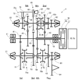
- FIG. 1st embodiment It is a block diagram which shows a part of gear seen from the axial direction of the transmission 1.
- FIG. 1 is a skeleton diagram showing an overall structure of a transmission 1.
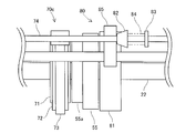
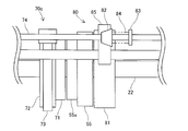
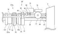
- FIG. It is a schematic diagram which shows the shift mechanism 70c and the parking mechanism 80. It is a figure which shows the principal part of the shift mechanism 70c of a neutral state, and the parking mechanism 80 of an unlocked state. It is a figure which shows the principal part of the shift mechanism 70c of a shift state, and the parking mechanism 80 of an unlocked state. It is a figure which shows the principal part of the shift mechanism 70c of a neutral state, and the parking mechanism 80 of a locked state.
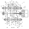
- 2nd embodiment It is a skeleton figure which shows the whole structure of the transmission 101.
- FIG. 1st embodiment It is a block diagram which shows a part of gear seen from the axial direction of the transmission 1.
- FIG. 1 is a skeleton diagram showing an overall structure of a transmission 1.
- FIG. It is
- the transmission 1 is a dual clutch transmission mounted on a vehicle.
- the transmission 1 includes a plurality of rotating shafts 11, 12, 21, and 22 that are rotatably supported by the case 2, a dual clutch 30 that transmits the rotational driving force of the internal combustion engine E / G to the rotating shaft, and a rotating shaft
- a plurality of transmission gears 41 to 46, 51 to 56, and 61 to 64 that are rotatably supported and constitute forward or reverse gears, shift mechanisms 70a to 70d that selectively establish each gear, and stopping of the vehicle
- a parking mechanism 80 that maintains the state is provided.
- the case 2 supports each shaft by a plurality of bearings, and contains lubricating oil to be supplied to the plurality of gears and sliding portions included in the shift mechanisms 70a to 70d.
- the case 2 houses a dual clutch 30 inside a clutch housing (not shown).
- the internal combustion engine E / G is a drive source mounted on a vehicle and corresponds to the “prime mover” of the present invention.
- the first input shaft 11 is a rotary shaft that is formed in a hollow shaft shape and is rotatably supported with respect to the case 2 by a bearing. Further, a portion for supporting the bearing and a plurality of external splines are formed on the outer peripheral surface of the first input shaft 11.
- the first input shaft 11 is directly formed with a first speed drive gear 41 and a large-diameter fifth speed drive gear 45.
- An external spline is formed on the outer peripheral surface of the first input shaft 11, and a three-speed drive gear 43 is press-fitted into the external spline by spline fitting. Further, the first input shaft 11 is formed with a connecting shaft portion that is connected to the first clutch 31 of the dual clutch 30.
- the second input shaft 12 is formed in a hollow shaft shape, is rotatably supported on a part of the outer periphery of the first input shaft 11 via a plurality of bearings, and is rotated with respect to the clutch housing of the case 2 by the bearings. It is a rotating shaft that is supported.
- the second input shaft 12 is disposed concentrically with the first input shaft 11 so as to be relatively rotatable.
- a portion for supporting the bearing and a plurality of external gears are formed on the outer peripheral surface of the second input shaft 12.
- the second input shaft 12 is formed with a two-speed drive gear 42 and a large-diameter four-speed drive gear 44 (six-speed drive gear 46).
- the four-speed drive gear 44 is a gear that meshes with the four-speed driven gear 54 and the sixth-speed driven gear 56 and is used as a drive-side gear that constitutes the fourth and sixth speed stages. Further, the second input shaft 12 is formed with a connecting shaft portion that is connected to the second clutch 32 of the dual clutch 30.
- the first output shaft 21 is a rotating shaft that is disposed in parallel to the first input shaft 11 inside the case 2 and is rotatably supported with respect to the case 2 by a bearing.
- a final reduction gear 61 and a plurality of external splines are formed on the outer peripheral surface of the first output shaft 21. Hubs 71 of shift mechanisms 70a and 70b described later are press-fitted into the external splines of the first output shaft 21 by spline fitting.
- the final reduction gear 61 is meshed with a ring gear 64 of a differential (differential mechanism).
- the first output shaft 21 is formed with a support portion that supports the first-speed driven gear 51, the third-speed driven gear 53, the fourth-speed driven gear 54, and the reverse gear 63 so as to be freely rotatable.
- the second output shaft 22 is a rotating shaft that is disposed in parallel with the first input shaft 11 inside the case 2 and is rotatably supported with respect to the case 2 by a bearing. Further, similarly to the first output shaft 21, a final reduction gear 62 and a plurality of external splines are formed on the outer peripheral surface of the second output shaft 22. Hubs 71 of shift mechanisms 70c and 70d described later and a parking gear 81 of the parking mechanism 80 are press-fitted into the external splines of the second output shaft 22 by spline fitting. The final reduction gear 62 meshes with a differential ring gear 64.
- the second output shaft 22 is formed with a support portion that supports the second-speed driven gear 52, the fifth-speed driven gear 55, and the sixth-speed driven gear 56 so as to be freely rotatable.
- the first output shaft 21 and the second output shaft 22 are caused by the difference in the transmission gears to be supported and the layout of each gear stage in the transmission 1.
- the second output shaft 22 has a shorter configuration.
- the dual clutch 30 includes a first clutch 31 that transmits the rotational driving force of the internal combustion engine E / G to the first input shaft 11, and the rotational driving force of the internal combustion engine E / G that is transmitted to the second input shaft. 12 and a second clutch 32 that transmits to 12.
- the dual clutch 30 is accommodated in the clutch housing of the case 2 and is provided concentrically with the first input shaft 11 and the second input shaft 12.
- the first clutch 31 is connected to the connecting shaft portion of the first input shaft 11, and the second clutch 32 is connected to the connecting shaft portion of the second input shaft 12.
- the dual clutch 30 switches the connection with the internal combustion engine E / G by the first clutch 31 and the second clutch 32 based on a control command input from the vehicle control device.
- the dual clutch type transmission can establish a shift stage to be used next in advance, and can change a high-speed shift by switching the clutch that transmits the rotational driving force.
- the reverse gear 63 is provided on a support portion of the reverse gear formed on the first output shaft 21 so as to be free-wheeling. Further, in the present embodiment, the reverse gear 63 is always meshed and rotationally connected to a small-diameter gear 52 a formed integrally with the second-speed driven gear 52. As shown in FIG. 1, the ring gear 64 meshes with the final reduction gear 61 and the final reduction gear 62 so as to be always rotationally connected to the first output shaft 21 and the second output shaft 22.
- the ring gear 64 constitutes a differential mechanism as a final gear in the transmission 1, and is connected to drive wheels via a drive shaft.
- the shift mechanisms 70a to 70d are controlled by a vehicle control device, and are a mechanism for switching between a shift state in which a gear position corresponding to a shift operation is established and a neutral state in which no gear stage is established.
- the transmission 1 is provided with shift mechanisms 70a to 70d at four locations, as shown in FIG.
- Each shift mechanism 70a to 70d is different in the target of the transmission gear connected to the first output shaft 21 or the second output shaft 22 among the transmission gears.
- the shift mechanism 70a is connected to the first speed driven gear 51 and the third speed driven gear 53.
- the shift mechanism 70b has the four-speed driven gear 54 and the reverse gear 63 as a connection target.
- the shift mechanism 70c has only the fifth speed driven gear 55 as a connection target.
- the shift mechanism 70d has the second speed driven gear 52 and the sixth speed driven gear 56 as the objects to be connected.
- the shift mechanisms 70a to 70d include a hub 71, a sleeve 72 (corresponding to the “connecting member” of the present invention), a shift fork 73, a fork shaft 74, a motor 75, The worm gear 76 and the worm wheel 77 are provided.
- the hub 71 has a hollow disk shape in which an internal spline and an external spline are formed.
- the hub 71 is a member that is press-fitted into the external spline of the first output shaft 21 or the second output shaft 22 by spline fitting, and rotates integrally with the press-fitted output shaft.
- the sleeve 72 meshes with an external spline of the hub 71 so as to be movable in the axial direction with respect to the hub 71.
- the sleeve 72 is slidable in the axial direction of the rotating shaft and can be engaged with the driven gears 51 to 56 of the shift stage or the piece gear portion of the reverse gear 63.
- each gear is connected to the supported output shaft and can rotate integrally.
- a synchronizing ring (not shown) is urged to a gear to be connected, and the rotation speed of the gear is synchronized with the rotation speed of the output shaft. Can be connected.
- the shift fork 73 is fixed to the fork shaft 74 and is fitted in a circumferential groove formed on the outer peripheral surface of the sleeve 72.
- the fork shaft 74 is a member that is provided so as to be movable in the axial direction of the rotary shaft and is moved to an axial position corresponding to the shift operation.
- the sleeve 72 is connected to the fork shaft 74 via the shift fork 73 and interlocks with the movement of the fork shaft 74 in the axial direction.
- the sleeve 72 is connected to the output shaft on which the driven gears 51 to 56 or the reverse gear 63 of the shift stage are supported according to the axial position where the fork shaft 74 is positioned, The gear is switched to a connection release state in which the connection with the output shaft is released.
- the motor 75 is an electric motor that is provided outside the transmission 1 and is driven to rotate by being supplied with electric power according to a shift operation by a vehicle control device.
- the worm gear 76 is a gear that is provided on the drive shaft of the motor 75 and rotates integrally with the rotation shaft as the motor 75 rotates.
- the worm wheel 77 is fixed to one end of a shaft (not shown) that is rotatably supported by the case 2, and transmits the rotational force of the worm gear 76 that meshes to the inside of the case 2.
- a pinion gear that meshes with a gear formed on the outer peripheral surface of the fork shaft 74 is provided at the other end of the shaft to which the worm wheel 77 is fixed.
- the fork shaft 74 is moved to a predetermined axial position by rotationally driving the motor 75, and the target transmission gear is set to the first output shaft 21 or the second output. Connected to the shaft 22 to establish a predetermined gear position.
- the shift mechanisms 70 a, 70 b, and 70 d have transmission gears arranged on both sides in the axial direction of the respective sleeves 72 as the objects to be connected.
- the shift mechanism 70c is connected to and disconnected from only the transmission gear, that is, the fifth-speed driven gear 55 disposed on one axial side of the sleeve 72 (the right side in FIG. 2). Is switched. That is, there is no transmission gear connected to the second output shaft 22 by the sleeve 72 on the other axial side of the sleeve 72 of the shift mechanism 70c (left side in FIG. 3).
- the parking mechanism 80 is a mechanism for holding the vehicle in a stopped state by preventing the rotation of the shaft connected to the drive wheels by restricting the rotation of the parking gear 81 when the vehicle is stopped. is there.
- the parking mechanism 80 includes a parking gear 81, a cam 82 (corresponding to the “cam member” of the present invention), a snap 83, a cam spring 84, and a parking pole 85 (main Corresponding to the “locking member” of the invention, a pole support shaft 86, and a torsion spring 87.
- the parking gear 81 has a plurality of external teeth formed on the outer peripheral surface thereof, and is press-fitted into an external spline formed on the outer peripheral surface of the second output shaft 22 to be fixed to the second output shaft 22.
- the parking gear 81 is fixed to the second output shaft 22 having a short axial length among the first output shaft 21 and the second output shaft 22.
- the cam 82 has a large-diameter portion formed on one side in the axial direction of the rotating shaft, and a small-diameter portion formed so that the outer diameter gradually decreases from the large-diameter portion toward the other side in the axial direction. ing.
- the cam 82 is slidably provided on the fork shaft 74 of the shift mechanism 70c.
- the snap 83 is formed in a disk shape and is fixed to the fork shaft 74 while being separated from the cam 82.
- the cam spring 84 is a coiled compression spring and is interposed between the cam 82 and the snap 83 on the outer peripheral side of the fork shaft 74.
- One end of the cam spring 84 is fixed to the snap 83 and the other end is fixed to the cam 82.
- the cam 82 is maintained at a distance from the snap 83 by the free length of the cam spring 84 when the cam spring 84 is not loaded.
- the parking pole 85 is supported by the case 2 via a pole support shaft 86.
- the parking pole 85 has a locking claw 85 a that meshes with the external teeth of the parking gear 81.
- the locking claw 85a meshes with external teeth formed on the outer peripheral surface of the parking gear 81, thereby restricting the rotation of the parking gear 81.
- the parking pole 85 has a locking position for restricting the rotation of the parking gear 81 by engaging the outer teeth of the parking gear 81 and the locking claws 85a with the pole support shaft 86 as the rotation center, and the outside of the parking gear 81.
- the parking gear 81 is allowed to move between a locking release position that allows rotation.
- the pole support shaft 86 is rotatably supported by the case 2 and a torsion spring 87 is disposed on the outer peripheral side thereof.
- the torsion spring 87 is a torsion spring and has one end fixed to the case 2 and the other end fixed to the pole support shaft 86. Accordingly, the parking pawl 85 is biased in a direction in which the locking claw 85 a is separated from the external teeth of the parking gear 81 by the elastic force of the torsion spring 87 via the pole support shaft 86.
- the parking pole 85 has a back surface portion (a portion on the upper side of the parking pole 85 in FIG. 1) opposite to the position where the locking claw 85 a is formed in contact with the outer peripheral surface of the fork shaft 74 or the cam 82. . That is, the parking pole 85 is moved to the unlocking position when the back surface portion thereof is in contact with the small diameter portion of the outer peripheral surface of the fork shaft 74 or the cam 82. Further, the parking pole 85 is moved to the locking position when the back surface portion thereof is in contact with the large diameter portion of the outer peripheral surface of the cam 82. In other words, since the cam 82 in the parking mechanism 80 is provided on the fork shaft 74, the parking pole 85 is moved to the locking position or the locking release position according to the axial position of the fork shaft 74.
- the transmission 1 shifts and transmits rotational driving force by controlling the dual clutch 30 and the shift mechanisms 70a to 70d.
- the parking mechanism 80 that holds the stopped state of the vehicle is provided with a cam 82 for operating the parking pole 85 and the like on the fork shaft 74. That is, in the transmission 1, the shift mechanism 70 c serves as a part of the parking mechanism 80. This is intended to operate the parking pole 85 without adding a parking rod that supports a cam or the like as in the prior art.
- the parking mechanism 80 since the parking mechanism 80 operates in accordance with the axial position of the fork shaft 74 of the shift mechanism 70c, operations of the shift mechanism 70c and the parking mechanism 80 will be described.
- the transmission 1 does not need to establish the fifth gear, for example, the vehicle is in a traveling state at the third gear.
- the transmission 1 moves the fork shaft 74 in the axial direction so that the sleeve 72 is in a neutral position in which the connection is released.
- the parking pole 85 has a back surface portion in contact with the outer peripheral surface of the fork shaft 74 and is in the unlocked position. Therefore, the shift mechanism 70c is in a neutral state, and the parking mechanism 80 is in an unlocked state where the rotation of the parking gear 81 is not restricted.
- the vehicle is brought into a traveling state at the fourth speed, and the dual clutch transmission 1 is required to establish the fifth speed in advance.
- the transmission 1 moves the fork shaft 74 to one side in the axial direction (the right side in FIG. 5) so that the sleeve 72 is in the shift position in which the sleeve 72 is connected as shown in FIG.
- the sleeve 72 synchronizes the rotation speed of the fifth speed driven gear 55 to be connected to the rotation speed of the second output shaft 22 by an action such as synchro ringing, and then the sleeve 72 is connected to the piece gear portion 55a of the fifth speed driven gear 55. It meshes and becomes a connected state.
- the shift mechanism 70c is in a shift state in which the fifth gear is established, and the parking mechanism 80 is in an unlocked state in which the rotation of the parking gear 81 is not restricted.
- this stopped state is set to a state that requires the transmission 1 to hold.
- the transmission 1 moves the fork shaft 74 from the axial position where the sleeve 72 is moved to the neutral position to the other axial side (left side in FIG. 6).
- the sleeve 72 maintains the disconnected state. It will be.
- the parking pole 85 comes into contact with the large diameter portion of the cam 82 and engages against the elastic force of the torsion spring 87. Move to the stop position. That is, the locking claw 85 a of the parking pole 85 meshes with the external teeth of the parking gear 81. Therefore, the parking mechanism 80 is in a locked state where the rotation of the parking gear 81 is restricted, and the shift mechanism 70c is in a neutral state.
- the locking claw 85a comes into contact with the external teeth of the parking gear 81 and moves to the locking position.
- the cam spring 84 interposed between the cam 82 and the snap 83 is reduced, and the cam 82 slides with respect to the fork shaft 74.
- the second output shaft 22 rotates via the ring gear 64 and the final reduction gear 62.
- the phase of the parking gear 81 with respect to the parking pole 85 is changed by the rotation of the second output shaft 22, and the locking claw 85 a can be engaged with the external teeth of the parking gear 81.
- the cam spring 84 extends and the large diameter portion of the cam 82 comes into contact with the back surface portion of the parking pole 85. In this way, even in the above case, the fork shaft 74 does not move, and the parking pole 85 can move to the locking position to enter a locked state in which the rotation of the parking gear 81 is restricted. .
- the fork shaft 74 is moved to an axial position where at least the sleeve 72 is moved to the neutral position.
- the transmission 1 sets the shift mechanism 70 c to the neutral state again and sets the parking mechanism 80 to the unlocked state in which the rotation of the parking gear 81 is not restricted.
- the transmission 1 configured as described above has the following effects.
- the transmission 1 has a configuration in which a cam 82 for moving the parking pole 85 to the locking position or the locking release position is provided on the fork shaft 74.
- the transmission 1 can operate the cam 82 using the shift mechanism 70c that moves the fork shaft 74 in the axial direction.
- the parking mechanism 80 can be provided without adding a parking rod or the like that supports the cam as in the prior art. Therefore, in the transmission 1 including a part of the parking mechanism 80, the number of parts can be reduced and the manufacturing cost can be reduced as compared with the conventional case. Furthermore, since the physique of the transmission 1 can be reduced in size, the mounting property on the vehicle can be improved.
- the fork shaft 74 of the shift mechanisms 70a to 70d can move at least as much as the axial stroke required to switch the operating sleeve 72 between the connected state and the disconnected state, that is, the distance from the neutral position to the shift position. Is supported by the case 2.
- the cam 82 is provided on the fork shaft 74 for the purpose of moving the sleeve 72 to the shift position, so that it is necessary for the cam 82 to operate in addition to the above stroke. It is necessary to support the fork shaft 74 such that the fork shaft 74 can be further moved by the stroke in the axial direction. That is, the transmission 1 is allowed to move to each axial position because the axial position where the cam 82 operates is set in addition to the axial position where the fork shaft 74 is originally positioned to function. It is necessary to
- the transmission 1 is provided with a sleeve 72 in which a transmission gear to be coupled is arranged only on one side, such as the shift mechanism 70c, due to the set number of shift stages, the layout of the transmission gear, and the like. There is. Therefore, by providing the cam 82 on the fork shaft 74 of the shift mechanism 70c, the stroke of the fork shaft 74 can be increased relatively easily. Therefore, the fork shaft 74 and the mechanism for moving the fork shaft 74 in the axial direction can be used effectively. Further, the parking mechanism 80 can be added while suppressing an increase in the axial length of the transmission 1 as a whole.
- the parking gear 81 is configured to be fixed to the second output shaft 22 having a short axial length among the first output shaft 21 and the second output shaft 22.
- a space for arranging the parking gear 81 on the rotation shaft is required by at least the axial width of the parking gear 81.
- the transmission 1 is a dual clutch type, it has a plurality of outputs, and the second output shaft 22 is more likely to be caused by the difference in the supported transmission gears and the layout of each gear stage in the transmission 1. It has a short configuration.
- the transmission 1 is a dual clutch type, and the parking gear 81 is fixed to the second output shaft. Since the dual clutch transmission 1 is provided with a plurality of shift mechanisms 70a to 70d for selectively connecting a plurality of transmission gears, there is a concern that the dual clutch transmission 1 may increase in size in the radial direction of the rotating shaft. Therefore, by providing the cam 82 on the existing fork shaft 74 as in this embodiment, the parking mechanism 80 can be suitably added without newly adding a parking rod or the like. Therefore, it is particularly useful to apply the present invention to a dual clutch transmission.
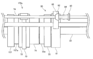
- the transmission 101 of this embodiment differs from the transmission 1 of the first embodiment in the configuration of a shift mechanism having a fork shaft 74 on which a cam 82 is disposed. More specifically, in the transmission 1 according to the first embodiment, the cam 82 is provided on the fork shaft 74 of the shift mechanism 70c in which the transmission gear to be coupled is arranged only on one side in the axial direction. On the other hand, in the transmission 101 of the present embodiment, the cam 82 is provided on the fork shaft 174 of the shift mechanism 170c in which the transmission gears to be coupled are arranged on both sides in the axial direction. Since other configurations are substantially the same as those of the first embodiment, detailed description thereof is omitted. Only the differences will be described below.
- the transmission 101 includes a first input shaft 111 and a second output shaft 122 that are rotatably supported by the case 2 and transmission gears 41 to 46, 147, 51 to 56 that constitute seven forward shift stages or reverse shift stages. , 157, 61 to 64, shift mechanisms 70a, 70b, 170c, 70d for selectively establishing the respective gear positions, and a parking mechanism 80 for holding the stopped state of the vehicle.
- the first input shaft 111 is a rotating shaft that is rotatably supported with respect to the case 2 by a bearing.
- An external spline is formed on the outer peripheral surface of the first input shaft 111, and a third speed drive gear 43 and a seventh speed drive gear 147 are press-fitted into the external spline by spline fitting.
- the second output shaft 122 is a rotating shaft that is disposed in parallel with the first input shaft 111 inside the case 2 and is rotatably supported with respect to the case 2 by a bearing.
- a plurality of external splines are formed on the outer peripheral surface of the second output shaft 122.
- Hubs 71 of shift mechanisms 170c and 70d, which will be described later, and a parking gear 81 of the parking mechanism 80 are press-fitted into the external splines of the second output shaft 122 by spline fitting.
- the second output shaft 122 is formed with a support portion that supports the second-speed driven gear 52, the fifth-speed driven gear 55, the sixth-speed driven gear 56, and the seventh-speed driven gear 157 so as to be freely rotatable.
- the fifth-speed driven gear 55 and the seventh-speed driven gear 157 are caused by the layout of the transmission gear in the transmission 101 and the like, as shown in FIGS.
- the width of the seventh-speed driven gear 157 is set larger.
- the configurations of the second input shaft 12, the first output shaft 21, the plurality of transmission gears supported by these rotating shafts, and the dual clutch 30 are substantially the same as those of the first embodiment.
- the shift mechanism 170c is a mechanism that is controlled by a vehicle control device and switches between a shift state in which a gear position corresponding to a shift operation is established and a neutral state in which no gear stage is established.
- the transmission 101 has shift mechanisms 70a, 70b, 170c, and 70d arranged at four locations, respectively, as shown in FIG.
- the shift mechanism 170c includes a five-speed driven gear 55 arranged on one side in the axial direction of the sleeve 72 (right side in FIG. 7) and a seven-speed driven gear arranged on the other side in the axial direction of the sleeve 72 (left side in FIG. 7). 157 is the subject of concatenation.
- the shift mechanism 170c configured as described above rotates the motor 75 to move the fork shaft 74 to a predetermined axial position, connects the target transmission gear to the second output shaft 122, and The gear position is established.
- the fifth speed driven gear 55 corresponds to the “first transmission gear” of the present invention
- the seventh speed driven gear 157 corresponds to the “second transmission gear” of the present invention.
- members constituting the shift mechanism 170c are substantially the same as those in the first embodiment.
- the transmission 101 is a dual clutch transmission, and the shift mechanism 170c also serves as a part of the parking mechanism 80, as in the first embodiment.
- the parking mechanism 80 since the parking mechanism 80 operates according to the axial position of the fork shaft 74 of the shift mechanism 170c, the operation of the shift mechanism 170c and the parking mechanism 80 will be described.
- the transmission 101 does not need to establish the fifth gear, for example, the vehicle is in a traveling state at the third gear.
- the transmission 101 moves the fork shaft 74 in the axial direction so that the sleeve 72 is in a neutral position where the connection is released.
- the parking pole 85 has a back surface portion in contact with the outer peripheral surface of the fork shaft 74 and is in the unlocked position. Therefore, the shift mechanism 70c is in a neutral state, and the parking mechanism 80 is in an unlocked state where the rotation of the parking gear 81 is not restricted.
- the vehicle enters a traveling state at the fourth speed, and the dual clutch type transmission 101 is required to establish the fifth speed in advance.
- the transmission 101 moves the fork shaft 74 to one side in the axial direction (the right side in FIG. 10) so that the sleeve 72 is in the shift position where the sleeve 72 is in the connected state, as shown in FIG.
- the sleeve 72 synchronizes the rotation speed of the fifth speed driven gear 55 to be connected to the rotation speed of the second output shaft 122 by an action such as synchro ringing, and then the sleeve 72 is connected to the piece gear portion 55a of the fifth speed driven gear 55. It meshes and becomes a connected state.
- the shift position of the sleeve 72 in this state corresponds to the “first shift position” of the present invention.
- the vehicle is in a traveling state at the sixth speed, and the dual clutch type transmission 101 is required to establish the seventh speed in advance.
- the transmission 101 moves the fork shaft 74 to the other side in the axial direction (left side in FIG. 11) so that the sleeve 72 is in the shift position where the sleeve 72 is in the connected state, as shown in FIG. 11.
- the sleeve 72 synchronizes the rotational speed of the seventh speed driven gear 157 to be connected to the rotational speed of the second output shaft 122 by an action such as synchro ringing, and then the sleeve 72 is connected to the piece gear portion 157a of the seventh speed driven gear 157. It meshes and becomes a connected state.
- the shift position of the sleeve 72 in this state corresponds to the “second shift position” of the present invention.
- the parking pole 85 has its back surface abutting against the outer peripheral surface of the fork shaft 74 and engaging. It is in the stop release position. Therefore, the shift mechanism 70c is in a shift state in which the fifth speed stage or the seventh speed stage is established, and the parking mechanism 80 is in an unlocked state in which the rotation of the parking gear 81 is not restricted.
- this stopped state is a state that requires the transmission 101 to hold.
- the transmission 101 moves the fork shaft 74 from the axial position where the sleeve 72 is moved to the second shift position to the other axial side (left side in FIG. 12).
- a transmission gear in this embodiment, a seventh speed driven gear 157 connected to the second output shaft 122 by the sleeve 72 is disposed. Therefore, the sleeve 72 is maintained in a connected state.
- the parking pole 85 comes into contact with the large diameter portion of the cam 82 and engages against the elastic force of the torsion spring 87. Move to the stop position. That is, the locking claw 85 a of the parking pole 85 meshes with the external teeth of the parking gear 81. Therefore, the parking mechanism 80 is in a locked state where the rotation of the parking gear 81 is restricted, and the shift mechanism 70c is in the shift state.
- the fork shaft 74 is moved to an axial position where at least the sleeve 72 is moved to the neutral position.
- the transmission 101 sets the shift mechanism 70 c to the neutral state again and sets the parking mechanism 80 to the unlocked state in which the rotation of the parking gear 81 is not restricted.
- the transmission 101 configured as described above has the same effects as the first embodiment.
- the fork shaft 74 of the shift mechanism 170c has an axial stroke required for the sleeve 72 to be operated to switch between the connected state and the disconnected state, that is, from the first shift position to the second shift position via the neutral position. Only the distance is supported by the case 2 so as to be movable at least.
- the transmission 101 of the present embodiment is provided with the cam 82 on the fork shaft 74 for the purpose of moving the sleeve 72 to each shift position. Therefore, it is necessary to support the fork shaft 74 such that the fork shaft 74 can be further moved by the axial stroke required for the cam 82 to operate. That is, the transmission 101 is allowed to move to each axial position because the axial position where the cam 82 operates is set in addition to the axial position where the fork shaft 74 is originally positioned to function. It is necessary to
- the transmission 101 is set such that the axial widths of the transmission gears arranged as the objects to be connected to both sides in the axial direction of the sleeve 72 are different due to the set number of shift stages and the layout of the transmission gears. May be. That is, in the fifth-speed driven gear 55 and the seventh-speed driven gear 157, the axial distance from the piece gear portions 55a and 157a meshing with the sleeve 72 to the portion having the tooth surface of each driven gear 55 and 157 is the fifth-speed driven gear.
- the seventh speed driven gear 157 may be set longer than the gear 55. Therefore, by providing the cam 82 on the fork shaft 74 of the shift mechanism 170c, the stroke of the fork shaft 74 can be increased relatively easily. Therefore, the fork shaft 74 and the mechanism for moving the fork shaft 74 in the axial direction can be used effectively. Further, the parking mechanism 80 can be added while suppressing an increase in the axial length of the transmission 101 as a whole.
- the transmissions 1 and 101 are dual clutch transmissions.
- a mechanical automatic transmission other than the dual clutch type may be used. That is, if the shift mechanism is configured to selectively establish each shift stage by moving the fork shaft in the axial direction, the present invention can be applied by providing the cam 82 on the fork shaft 74. Further, in the case of a mechanical automatic transmission, when a plurality of output shafts are provided, the parking gear 81 is fixed to the shorter axial length, thereby securing the space associated with the arrangement of the parking gear 81 as described above. Therefore, it is possible to prevent the physique from increasing in size as a whole of the transmissions 1 and 101.
- each of the shift mechanisms 70a to 70d, 170c has a motor 75 as a power source for moving the fork shaft 74.
- a motor 75 as a power source for moving the fork shaft 74.
- a pinion gear is provided at the other end of the shaft to which the worm wheel 77 is fixed.
- the present invention can be applied. Besides, for example, a hydraulic cylinder or a drum using a solenoid valve is used as a motor.
- the present invention can be applied even if the rotating shift mechanism is configured to move the fork shaft in the axial direction. In any configuration, the same effects as described above can be obtained.
- the parking gear 81 of the parking mechanism 80 is fixed to the second output shafts 22 and 122.
- the parking gear 81 may be fixed to any rotation shaft as long as the rotation shaft is always rotationally connected to the ring gear 64 connected to the drive wheel. That is, since the final reduction gear 61 fixed to the first output shaft 11 is always rotationally connected to the ring gear 64, the parking gear 81 may be fixed to the first output shaft 11.
- the present invention is intended to operate the parking mechanism 80 using a shift mechanism that moves the fork shaft 74 in the axial direction. Therefore, the rotation shaft that supports the transmission gear to be connected by the shift mechanism having the fork shaft 74 provided with the cam 82 and the rotation shaft to which the parking gear 81 is fixed are not necessarily the same.
- a cam member may be provided on the fork shaft 74 of the shift mechanism 70c to be connected to the fifth-speed driven gear 55 supported by the second output shaft, and the parking gear 81 may be fixed to the first output shaft.
- the sleeve 72 when the parking mechanism 80 is switched to the locked state, the sleeve 72 is configured to move from the neutral position or the second shift position to the other side in the axial direction.
- the sleeve 72 in order to put the parking mechanism 80 in the locked state, it is necessary to move at least the fork shaft 74 in addition to the axial position where the fork shaft 74 is originally positioned to function. Therefore, the sleeve 72 may not necessarily be interlocked with the additional movement of the fork shaft 74.
- the shift fork 73 slides relative to the fork shaft 74 to maintain the position of the sleeve 72, or a circumferential groove formed on the outer peripheral surface of the sleeve 72. Further, the shift fork 73 may be temporarily removed from the first position so that the position of the sleeve 72 is maintained.
Abstract
Description
本発明は、上記課題を鑑みてなされたものであり、部品点数を減らし製造コストを低減すると共に、体格を小型化し車両への搭載性を向上することが可能な変速機を提供することを目的とする。 However, in the parking mechanism of
The present invention has been made in view of the above problems, and an object of the present invention is to provide a transmission capable of reducing the number of parts, reducing the manufacturing cost, and reducing the size and improving the mountability on a vehicle. And
(変速機1の構成)
本実施形態における変速機1の構成について、図1~図3を参照して説明する。変速機1は、車両に搭載されるデュアルクラッチ式の変速機としている。変速機1は、ケース2に回転可能に支持された複数の回転軸11,12,21,22と、内燃機関E/Gの回転駆動力を回転軸に伝達するデュアルクラッチ30と、回転軸に回転可能に支持され前進または後進の変速段を構成する複数の変速ギヤ41~46,51~56,61~64と、各変速段を選択的に成立させるシフト機構70a~70dと、車両の停車状態を保持するパーキング機構80を備える。ケース2は、複数の軸受けにより各軸を支承するとともに、上記の複数のギヤおよびシフト機構70a~70dに含まれる摺動部に供給する潤滑油を収容している。また、ケース2は、図示しないクラッチハウジングの内部にデュアルクラッチ30を収容している。内燃機関E/Gは、車両に搭載された駆動源であって、本発明の「原動機」に相当する。 <First embodiment>
(Configuration of transmission 1)
The configuration of the
次に、変速機1の動作について、図4~図6を参照して説明する。変速機1は、デュアルクラッチ30およびシフト機構70a~70dを制御することにより、シフト変更および回転駆動力の伝達を行っている。また、車両の停車状態を保持するパーキング機構80は、パーキングポール85を作動させるカム82などをフォークシャフト74に設けている。つまり、変速機1において、シフト機構70cがパーキング機構80の一部を兼ねる構成としている。これは、従来のようにカムなどを支持するパーキングロッドを追加することなく、パーキングポール85を作動させることを目的としている。本実施形態では、シフト機構70cのフォークシャフト74の軸方向位置に応じてパーキング機構80が動作することから、このシフト機構70cおよびパーキング機構80の動作について説明する。 (Operation of transmission 1)
Next, the operation of the
以上説明したように構成される変速機1により以下の効果を奏する。変速機1は、パーキングポール85を係止位置または係止解除位置に移動させるためのカム82をフォークシャフト74に設ける構成としている。これにより、変速機1は、フォークシャフト74を軸方向に移動させるシフト機構70cを利用して、カム82を作動させることができる。これにより、従来のようにカムを支持するパーキングロッドなどを追加することなくパーキング機構80を設けることができる。よって、パーキング機構80の一部を備える変速機1において、従来と比較して部品点数を減らし製造コストを低減することができる。さらに、変速機1の体格を小型化することができるので、車両への搭載性を向上することができる。 (Effects of transmission 1)
The
本実施形態の変速機101は、第一実施形態の変速機1に対して、カム82が配置されるフォークシャフト74を有するシフト機構の構成が相違する。より具体的には、第一実施形態の変速機1では、軸方向一側のみに連結の対象とする変速ギヤを配置されたシフト機構70cのフォークシャフト74にカム82を設ける構成とした。これに対して、本実施形態の変速機101では、軸方向両側に連結の対象とする変速ギヤを配置されたシフト機構170cのフォークシャフト174にカム82を設ける構成としている。なお、その他の構成については、第一実施形態と実質的に同一であるため、詳細な説明を省略する。以下、相違点のみについて説明する。 <Second embodiment>
The
本実施形態における変速機101の構成について、図7,図8を参照して説明する。変速機101は、ケース2に回転可能に支持された第一入力軸111および第二出力軸122と、前進7変速段または後進の変速段を構成する変速ギヤ41~46,147,51~56,157,61~64と、各変速段を選択的に成立させるシフト機構70a,70b,170c,70dと、車両の停車状態を保持するパーキング機構80を備える。第一入力軸111は、軸受によりケース2に対して回転可能に支承されている回転軸である。また、第一入力軸111の外周面に外歯スプラインが形成され、この外歯スプラインに三速駆動ギヤ43および七速駆動ギヤ147がスプライン嵌合により圧入されている。 (Configuration of transmission 101)
The configuration of the
次に、変速機101の動作について、図9~図12を参照して説明する。変速機101は、デュアルクラッチ式の変速機であって、第一実施形態と同様に、シフト機構170cがパーキング機構80の一部を兼ねる構成としている。そして、本実施形態では、シフト機構170cのフォークシャフト74の軸方向位置に応じてパーキング機構80が動作することから、このシフト機構170cおよびパーキング機構80の動作について説明する。 (Operation of transmission 101)
Next, the operation of the
以上説明したように構成される変速機101により第一実施形態と同様の効果を奏する。また、シフト機構170cのフォークシャフト74は、作動させるスリーブ72が連結状態または連結解除状態を切換えるために要する軸方向のストロークの分、即ち第一シフト位置から中立位置を介して第二シフト位置までの距離だけは少なくとも移動可能にケース2に支持されている。また、本実施形態の変速機101は、第一実施形態と同様に、スリーブ72を各シフト位置に移動させることを目的とするフォークシャフト74にカム82を設けているので、上記のストロークに加えてカム82が作動するために要する軸方向のストロークの分だけさらに移動可能にフォークシャフト74を支持する必要がある。つまり、変速機101は、フォークシャフト74が本来機能すべく位置決めされる軸方向位置に加えて、カム82が作動する軸方向位置が設定されるので、それぞれの軸方向位置への移動を許容される必要がある。 (Effects of transmission 101)
The
第一、第二実施形態において、変速機1,101は、デュアルクラッチ式の変速機とした。これに対して、デュアルクラッチ式以外の例えば機械式自動変速機としてもよい。つまり、シフト機構がフォークシャフトの軸方向の移動により各変速段を選択的に成立させる構成であれば、そのフォークシャフト74にカム82を設けることで本発明を適用することが可能である。また、機械式自動変速機の場合も複数の出力軸を備える場合は、軸方向長さが短い方にパーキングギヤ81を固定することにより、上述したように、パーキングギヤ81の配置に伴うスペース確保を許容することができるので、変速機1,101全体として体格が大型化することを防止できる。 <Modification of the first and second embodiments>
In the first and second embodiments, the
11,111:第一入力軸、 12:第二入力軸
21:第一出力軸、 22,122:第二出力軸
30:デュアルクラッチ、 31:第一クラッチ、 32:第二クラッチ
41~46,147:変速段の駆動ギヤ
51~56,157:変速段の従動ギヤ、 52a:小径ギヤ
55a,157a:ピースギヤ部
61,62:最終減速ギヤ、 63:後進ギヤ、 64:リングギヤ
70a~70d,170c:シフト機構、 71:ハブ
72:スリーブ(連結部材)、 73:シフトフォーク
74:フォークシャフト、 75:モーター、 76:ウォームギヤ
77ウォームホイール
80:パーキング機構、 81:パーキングギヤ
82:カム(カム部材)、 83:スナップ、 84:カムスプリング
85:パーキングポール(係止部材)、 85a:係止爪
86:ポール支持シャフト、 87:トーションスプリング
E/G:内燃機関(原動機) 1, 101: Transmission, 2:
Claims (5)
- ケースと、
前記ケースに回転可能に支持された回転軸と、
前記回転軸に回転可能に支持された変速ギヤと、
前記回転軸の軸方向に移動可能に設けられ、シフト操作に応じた軸方向位置に移動されるフォークシャフトと、
前記フォークシャフトの移動と連動して前記回転軸の軸方向に移動可能に設けられ、前記フォークシャフトの軸方向位置に応じて前記変速ギヤが前記回転軸に連結された連結状態と前記変速ギヤが前記回転軸との連結を解除された連結解除状態とを切換える連結部材と、
前記回転軸に固定されたパーキングギヤと、
前記パーキングギヤに係止可能に前記ケースに設けられ、前記パーキングギヤの回転を規制する係止位置と前記パーキングギヤの回転を許容する係止解除位置との間で移動する係止部材と、
前記フォークシャフトに設けられ、前記フォークシャフトの軸方向位置に応じて前記係止部材を前記係止位置または前記係止解除位置に移動させるカム部材と、
を備える変速機。 Case and
A rotating shaft rotatably supported by the case;
A transmission gear rotatably supported on the rotating shaft;
A fork shaft provided so as to be movable in the axial direction of the rotary shaft, and moved to an axial position according to a shift operation;
A connection state in which the transmission gear is connected to the rotation shaft according to the axial position of the fork shaft and the transmission gear is provided so as to be movable in the axial direction of the rotation shaft in conjunction with the movement of the fork shaft. A connection member for switching between a connection release state released from the connection with the rotation shaft,
A parking gear fixed to the rotating shaft;
A locking member that is provided in the case so as to be able to be locked to the parking gear, and moves between a locking position that restricts rotation of the parking gear and a lock releasing position that allows rotation of the parking gear;
A cam member which is provided on the fork shaft and moves the locking member to the locking position or the locking release position according to the axial position of the fork shaft;
A transmission comprising: - 請求項1において、
前記連結部材により前記回転軸に連結される前記変速ギヤが当該連結部材の軸方向一側にのみ配置され、
前記連結部材は、前記フォークシャフトの軸方向の移動によって、前記連結解除状態とする中立位置から軸方向一側に位置するシフト位置に移動することにより前記変速ギヤを前記回転軸に連結して前記連結状態に切換え、
前記フォークシャフトが前記連結部材を前記中立位置に移動させる軸方向位置から軸方向他側に移動されることにより、前記連結部材が前記連結解除状態を維持して、前記カム部材が前記係止部材を前記係止位置に移動させる変速機。 In claim 1,
The transmission gear connected to the rotating shaft by the connecting member is disposed only on one side in the axial direction of the connecting member,
The connecting member connects the transmission gear to the rotating shaft by moving from a neutral position in the released state to a shift position located on one side in the axial direction by the axial movement of the fork shaft. Switch to connected state,
When the fork shaft is moved from the axial position that moves the connecting member to the neutral position, the connecting member maintains the released state, and the cam member is the locking member. A transmission for moving the gear to the locking position. - 請求項1において、
前記変速機は、前記連結部材により前記回転軸に連結される前記変速ギヤであって、前記連結部材の軸方向一側に配置される第一変速ギヤと、前記連結部材の軸方向他側に配置される第二変速ギヤと、を備え、
前記連結部材は、前記フォークシャフトの軸方向の移動によって、前記連結解除状態とする中立位置から軸方向一側に位置する第一シフト位置において前記第一変速ギヤを前記回転軸に連結して前記連結状態に切換え、また前記中立位置から軸方向他側に位置する第二シフト位置において前記第二変速ギヤを前記回転軸に連結して前記連結状態に切換え、
前記第二変速ギヤの軸方向幅は、前記第一変速ギヤの軸方向幅よりも大きく設定され、
前記フォークシャフトが前記連結部材を前記第二シフト位置に移動させる軸方向位置から軸方向他側に移動されることにより、前記連結部材が前記連結状態を維持して、前記カム部材が前記係止部材を前記係止位置に移動させる変速機。 In claim 1,
The transmission is the transmission gear connected to the rotation shaft by the connecting member, the first transmission gear disposed on one axial side of the connecting member, and the other axial side of the connecting member. A second transmission gear arranged,
The connecting member connects the first transmission gear to the rotating shaft at a first shift position located on one side in the axial direction from a neutral position in the disconnected state by the movement of the fork shaft in the axial direction. Switching to the connected state, and connecting the second transmission gear to the rotating shaft at the second shift position located on the other side in the axial direction from the neutral position, and switching to the connected state,
The axial width of the second transmission gear is set larger than the axial width of the first transmission gear,
The fork shaft is moved from the axial position for moving the connecting member to the second shift position to the other side in the axial direction, so that the connecting member maintains the connected state, and the cam member is locked. A transmission for moving a member to the locking position. - 請求項1~3の何れか一項において、
前記回転軸は、前記変速ギヤのうち出力側のギヤを支持し互いに軸方向長さが異なる複数の出力軸を有し、
複数の前記出力軸のうち軸方向長さが短い方に前記パーキングギヤが固定されている変速機。 In any one of claims 1 to 3,
The rotating shaft has a plurality of output shafts that support an output-side gear of the transmission gears and have different axial lengths from each other,
A transmission in which the parking gear is fixed to the shorter one of the plurality of output shafts in the axial direction. - 請求項1~4の何れか一項において、
前記回転軸は、複数の前記変速ギヤを支持し、互いに同心に配置され複数の前記変速ギヤのうち入力側のギヤを支持する第一入力軸および第二入力軸と、前記第一入力軸および第二入力軸と平行にそれぞれ配置され複数の前記変速ギヤのうち出力側のギヤを支持する第一出力軸および第二出力軸と、を有し、
原動機の回転駆動力を前記第一入力軸に伝達する第一クラッチと、前記回転駆動力を第二入力軸に伝達する第二クラッチとを有するデュアルクラッチをさらに備え、
前記パーキングギヤが前記第一出力軸および前記第二出力軸の何れか一方に固定されている変速機。 In any one of claims 1 to 4,
The rotating shaft supports a plurality of the transmission gears, is arranged concentrically with each other, and includes a first input shaft and a second input shaft that support an input-side gear among the plurality of transmission gears, the first input shaft, A first output shaft and a second output shaft that are arranged in parallel with the second input shaft and support an output-side gear among the plurality of transmission gears,
A dual clutch having a first clutch that transmits the rotational driving force of the prime mover to the first input shaft; and a second clutch that transmits the rotational driving force to the second input shaft;
A transmission in which the parking gear is fixed to one of the first output shaft and the second output shaft.
Priority Applications (4)
| Application Number | Priority Date | Filing Date | Title |
|---|---|---|---|
| US14/008,242 US20140083218A1 (en) | 2011-03-29 | 2012-03-29 | Transmission |
| KR1020137013603A KR20140051105A (en) | 2011-03-29 | 2012-03-29 | Transmission |
| CN2012800042978A CN103282699A (en) | 2011-03-29 | 2012-03-29 | Transmission |
| EP12765293.1A EP2693084A1 (en) | 2011-03-29 | 2012-03-29 | Transmission |
Applications Claiming Priority (2)
| Application Number | Priority Date | Filing Date | Title |
|---|---|---|---|
| JP2011071946A JP2012207687A (en) | 2011-03-29 | 2011-03-29 | Transmission |
| JP2011-071946 | 2011-03-29 |
Publications (1)
| Publication Number | Publication Date |
|---|---|
| WO2012133621A1 true WO2012133621A1 (en) | 2012-10-04 |
Family
ID=46931323
Family Applications (1)
| Application Number | Title | Priority Date | Filing Date |
|---|---|---|---|
| PCT/JP2012/058315 WO2012133621A1 (en) | 2011-03-29 | 2012-03-29 | Transmission |
Country Status (6)
| Country | Link |
|---|---|
| US (1) | US20140083218A1 (en) |
| EP (1) | EP2693084A1 (en) |
| JP (1) | JP2012207687A (en) |
| KR (1) | KR20140051105A (en) |
| CN (1) | CN103282699A (en) |
| WO (1) | WO2012133621A1 (en) |
Cited By (1)
| Publication number | Priority date | Publication date | Assignee | Title |
|---|---|---|---|---|
| CN115451106A (en) * | 2022-09-29 | 2022-12-09 | 赛力斯集团股份有限公司 | Transmission assembly |
Families Citing this family (7)
| Publication number | Priority date | Publication date | Assignee | Title |
|---|---|---|---|---|
| JP5738136B2 (en) | 2011-09-13 | 2015-06-17 | アイシン・エーアイ株式会社 | transmission |
| KR101462805B1 (en) * | 2013-09-30 | 2014-11-20 | 현대위아 주식회사 | Parking device for an electric vehicle |
| KR101610089B1 (en) * | 2014-09-23 | 2016-04-07 | 현대자동차 주식회사 | Transmission system of hybrid electric vehicle |
| JP6428556B2 (en) * | 2015-10-09 | 2018-11-28 | スズキ株式会社 | Vehicle transmission |
| CN108340775B (en) * | 2016-01-27 | 2020-11-20 | 陈安 | Electric automobile |
| US11313464B2 (en) * | 2018-04-26 | 2022-04-26 | Gkn Automotive Limited | Parking lock unit and drive arrangement |
| CA3196541A1 (en) * | 2020-11-03 | 2022-05-12 | Max Meyer LIBEN | Electric motor with integrated inverter and shared cooling system |
Citations (4)
| Publication number | Priority date | Publication date | Assignee | Title |
|---|---|---|---|---|
| JPH111158A (en) | 1997-06-13 | 1999-01-06 | Nissan Motor Co Ltd | Automatic transmission parking device |
| JP2007147057A (en) * | 2005-10-31 | 2007-06-14 | Aichi Mach Ind Co Ltd | Automatic-shift transmission and automobile equipped therewith |
| JP2009243557A (en) * | 2008-03-31 | 2009-10-22 | Aisin Aw Co Ltd | Parking device for automatic transmission |
| JP2010007754A (en) | 2008-06-26 | 2010-01-14 | Mitsubishi Fuso Truck & Bus Corp | Parking structure of transmission |
Family Cites Families (4)
| Publication number | Priority date | Publication date | Assignee | Title |
|---|---|---|---|---|
| JP2005325996A (en) * | 2004-04-15 | 2005-11-24 | Nissan Motor Co Ltd | Parking mechanism for vehicular meshing automatic transmission |
| JP2008039112A (en) * | 2006-08-08 | 2008-02-21 | Toyota Motor Corp | Shifting device of automatic transmission |
| JP4281841B1 (en) * | 2008-02-07 | 2009-06-17 | 三菱自動車工業株式会社 | Vehicle transmission |
| JP4861455B2 (en) * | 2009-07-15 | 2012-01-25 | ジヤトコ株式会社 | Automatic transmission |
-
2011
- 2011-03-29 JP JP2011071946A patent/JP2012207687A/en not_active Withdrawn
-
2012
- 2012-03-29 KR KR1020137013603A patent/KR20140051105A/en not_active Application Discontinuation
- 2012-03-29 WO PCT/JP2012/058315 patent/WO2012133621A1/en active Application Filing
- 2012-03-29 US US14/008,242 patent/US20140083218A1/en not_active Abandoned
- 2012-03-29 EP EP12765293.1A patent/EP2693084A1/en not_active Withdrawn
- 2012-03-29 CN CN2012800042978A patent/CN103282699A/en active Pending
Patent Citations (4)
| Publication number | Priority date | Publication date | Assignee | Title |
|---|---|---|---|---|
| JPH111158A (en) | 1997-06-13 | 1999-01-06 | Nissan Motor Co Ltd | Automatic transmission parking device |
| JP2007147057A (en) * | 2005-10-31 | 2007-06-14 | Aichi Mach Ind Co Ltd | Automatic-shift transmission and automobile equipped therewith |
| JP2009243557A (en) * | 2008-03-31 | 2009-10-22 | Aisin Aw Co Ltd | Parking device for automatic transmission |
| JP2010007754A (en) | 2008-06-26 | 2010-01-14 | Mitsubishi Fuso Truck & Bus Corp | Parking structure of transmission |
Cited By (2)
| Publication number | Priority date | Publication date | Assignee | Title |
|---|---|---|---|---|
| CN115451106A (en) * | 2022-09-29 | 2022-12-09 | 赛力斯集团股份有限公司 | Transmission assembly |
| CN115451106B (en) * | 2022-09-29 | 2024-04-23 | 赛力斯集团股份有限公司 | Transmission assembly |
Also Published As
| Publication number | Publication date |
|---|---|
| CN103282699A (en) | 2013-09-04 |
| KR20140051105A (en) | 2014-04-30 |
| JP2012207687A (en) | 2012-10-25 |
| EP2693084A1 (en) | 2014-02-05 |
| US20140083218A1 (en) | 2014-03-27 |
Similar Documents
| Publication | Publication Date | Title |
|---|---|---|
| WO2012133621A1 (en) | Transmission | |
| JP6286460B2 (en) | Planetary gear mechanism and transmission | |
| JP5276079B2 (en) | Automatic transmission | |
| JP4179385B2 (en) | Vehicle transmission | |
| US9360110B2 (en) | Transmission apparatus | |
| JP4240129B2 (en) | Vehicle transmission | |
| US8127635B2 (en) | Twin clutch transmission | |
| US8925410B2 (en) | Synchronizer for transmission | |
| JP2009154610A (en) | Multi-clutch type transmission | |
| JP4844239B2 (en) | Double clutch transmission | |
| JP5276272B2 (en) | Industrial vehicle transmission | |
| JP5329477B2 (en) | transmission | |
| KR101390338B1 (en) | Shifting apparatus for dual clutch transmission | |
| KR102001552B1 (en) | Shifting apparatus for dual clutch transmission | |
| JP5217483B2 (en) | Interlock mechanism of transmission | |
| JP2011163458A (en) | Shift operation device for automatic transmission | |
| US20180072148A1 (en) | Gear operating mechanism in transmission | |
| JP2007321818A (en) | Double clutch transmission | |
| JP2014185743A (en) | Transmission device | |
| KR101390339B1 (en) | Shifting apparatus for dual clutch transmission | |
| JP2006029511A (en) | Vehicular shift operating device | |
| JP6665567B2 (en) | Multi-stage transmission | |
| KR101568754B1 (en) | Shifting apparatus for dual clutch transmission | |
| JP2011127660A (en) | Shift operating device of automatic transmission | |
| KR101420699B1 (en) | Shifting apparatus for dual clutch transmission |
Legal Events
| Date | Code | Title | Description |
|---|---|---|---|
| 121 | Ep: the epo has been informed by wipo that ep was designated in this application |
Ref document number: 12765293 Country of ref document: EP Kind code of ref document: A1 |
|
| ENP | Entry into the national phase |
Ref document number: 20137013603 Country of ref document: KR Kind code of ref document: A |
|
| NENP | Non-entry into the national phase |
Ref country code: DE |
|
| WWE | Wipo information: entry into national phase |
Ref document number: 2012765293 Country of ref document: EP |
|
| WWE | Wipo information: entry into national phase |
Ref document number: 14008242 Country of ref document: US |