JP5738136B2 - transmission - Google Patents
transmission Download PDFInfo
- Publication number
- JP5738136B2 JP5738136B2 JP2011199823A JP2011199823A JP5738136B2 JP 5738136 B2 JP5738136 B2 JP 5738136B2 JP 2011199823 A JP2011199823 A JP 2011199823A JP 2011199823 A JP2011199823 A JP 2011199823A JP 5738136 B2 JP5738136 B2 JP 5738136B2
- Authority
- JP
- Japan
- Prior art keywords
- shaft
- case
- parking
- pair
- locking
- Prior art date
- Legal status (The legal status is an assumption and is not a legal conclusion. Google has not performed a legal analysis and makes no representation as to the accuracy of the status listed.)
- Expired - Fee Related
Links
Images

Classifications
-
- B—PERFORMING OPERATIONS; TRANSPORTING
- B60—VEHICLES IN GENERAL
- B60T—VEHICLE BRAKE CONTROL SYSTEMS OR PARTS THEREOF; BRAKE CONTROL SYSTEMS OR PARTS THEREOF, IN GENERAL; ARRANGEMENT OF BRAKING ELEMENTS ON VEHICLES IN GENERAL; PORTABLE DEVICES FOR PREVENTING UNWANTED MOVEMENT OF VEHICLES; VEHICLE MODIFICATIONS TO FACILITATE COOLING OF BRAKES
- B60T1/00—Arrangements of braking elements, i.e. of those parts where braking effect occurs specially for vehicles
- B60T1/12—Arrangements of braking elements, i.e. of those parts where braking effect occurs specially for vehicles acting otherwise than by retarding wheels, e.g. jet action
-
- B—PERFORMING OPERATIONS; TRANSPORTING
- B60—VEHICLES IN GENERAL
- B60T—VEHICLE BRAKE CONTROL SYSTEMS OR PARTS THEREOF; BRAKE CONTROL SYSTEMS OR PARTS THEREOF, IN GENERAL; ARRANGEMENT OF BRAKING ELEMENTS ON VEHICLES IN GENERAL; PORTABLE DEVICES FOR PREVENTING UNWANTED MOVEMENT OF VEHICLES; VEHICLE MODIFICATIONS TO FACILITATE COOLING OF BRAKES
- B60T1/00—Arrangements of braking elements, i.e. of those parts where braking effect occurs specially for vehicles
- B60T1/005—Arrangements of braking elements, i.e. of those parts where braking effect occurs specially for vehicles by locking of wheel or transmission rotation
-
- B—PERFORMING OPERATIONS; TRANSPORTING
- B60—VEHICLES IN GENERAL
- B60T—VEHICLE BRAKE CONTROL SYSTEMS OR PARTS THEREOF; BRAKE CONTROL SYSTEMS OR PARTS THEREOF, IN GENERAL; ARRANGEMENT OF BRAKING ELEMENTS ON VEHICLES IN GENERAL; PORTABLE DEVICES FOR PREVENTING UNWANTED MOVEMENT OF VEHICLES; VEHICLE MODIFICATIONS TO FACILITATE COOLING OF BRAKES
- B60T1/00—Arrangements of braking elements, i.e. of those parts where braking effect occurs specially for vehicles
- B60T1/02—Arrangements of braking elements, i.e. of those parts where braking effect occurs specially for vehicles acting by retarding wheels
- B60T1/06—Arrangements of braking elements, i.e. of those parts where braking effect occurs specially for vehicles acting by retarding wheels acting otherwise than on tread, e.g. employing rim, drum, disc, or transmission or on double wheels
- B60T1/062—Arrangements of braking elements, i.e. of those parts where braking effect occurs specially for vehicles acting by retarding wheels acting otherwise than on tread, e.g. employing rim, drum, disc, or transmission or on double wheels acting on transmission parts
-
- F—MECHANICAL ENGINEERING; LIGHTING; HEATING; WEAPONS; BLASTING
- F16—ENGINEERING ELEMENTS AND UNITS; GENERAL MEASURES FOR PRODUCING AND MAINTAINING EFFECTIVE FUNCTIONING OF MACHINES OR INSTALLATIONS; THERMAL INSULATION IN GENERAL
- F16D—COUPLINGS FOR TRANSMITTING ROTATION; CLUTCHES; BRAKES
- F16D63/00—Brakes not otherwise provided for; Brakes combining more than one of the types of groups F16D49/00 - F16D61/00
- F16D63/006—Positive locking brakes
-
- F—MECHANICAL ENGINEERING; LIGHTING; HEATING; WEAPONS; BLASTING
- F16—ENGINEERING ELEMENTS AND UNITS; GENERAL MEASURES FOR PRODUCING AND MAINTAINING EFFECTIVE FUNCTIONING OF MACHINES OR INSTALLATIONS; THERMAL INSULATION IN GENERAL
- F16H—GEARING
- F16H63/00—Control outputs from the control unit to change-speed- or reversing-gearings for conveying rotary motion or to other devices than the final output mechanism
- F16H63/02—Final output mechanisms therefor; Actuating means for the final output mechanisms
- F16H63/30—Constructional features of the final output mechanisms
- F16H63/34—Locking or disabling mechanisms
- F16H63/3416—Parking lock mechanisms or brakes in the transmission
- F16H63/3425—Parking lock mechanisms or brakes in the transmission characterised by pawls or wheels
- F16H63/3433—Details of latch mechanisms, e.g. for keeping pawls out of engagement
-
- F—MECHANICAL ENGINEERING; LIGHTING; HEATING; WEAPONS; BLASTING
- F16—ENGINEERING ELEMENTS AND UNITS; GENERAL MEASURES FOR PRODUCING AND MAINTAINING EFFECTIVE FUNCTIONING OF MACHINES OR INSTALLATIONS; THERMAL INSULATION IN GENERAL
- F16D—COUPLINGS FOR TRANSMITTING ROTATION; CLUTCHES; BRAKES
- F16D2125/00—Components of actuators
- F16D2125/18—Mechanical mechanisms
- F16D2125/58—Mechanical mechanisms transmitting linear movement
- F16D2125/66—Wedges
-
- F—MECHANICAL ENGINEERING; LIGHTING; HEATING; WEAPONS; BLASTING
- F16—ENGINEERING ELEMENTS AND UNITS; GENERAL MEASURES FOR PRODUCING AND MAINTAINING EFFECTIVE FUNCTIONING OF MACHINES OR INSTALLATIONS; THERMAL INSULATION IN GENERAL
- F16H—GEARING
- F16H63/00—Control outputs from the control unit to change-speed- or reversing-gearings for conveying rotary motion or to other devices than the final output mechanism
- F16H63/02—Final output mechanisms therefor; Actuating means for the final output mechanisms
- F16H63/30—Constructional features of the final output mechanisms
- F16H63/34—Locking or disabling mechanisms
- F16H63/3416—Parking lock mechanisms or brakes in the transmission
-
- Y—GENERAL TAGGING OF NEW TECHNOLOGICAL DEVELOPMENTS; GENERAL TAGGING OF CROSS-SECTIONAL TECHNOLOGIES SPANNING OVER SEVERAL SECTIONS OF THE IPC; TECHNICAL SUBJECTS COVERED BY FORMER USPC CROSS-REFERENCE ART COLLECTIONS [XRACs] AND DIGESTS
- Y10—TECHNICAL SUBJECTS COVERED BY FORMER USPC
- Y10T—TECHNICAL SUBJECTS COVERED BY FORMER US CLASSIFICATION
- Y10T74/00—Machine element or mechanism
- Y10T74/21—Elements
- Y10T74/2133—Pawls and ratchets
- Y10T74/2136—Pivoted pawls
- Y10T74/2137—Single tooth
Landscapes
- Engineering & Computer Science (AREA)
- Mechanical Engineering (AREA)
- General Engineering & Computer Science (AREA)
- Transportation (AREA)
- Gear-Shifting Mechanisms (AREA)
Description
本発明は、車両の停車状態を保持するパーキング機構を備えた変速機に関するものである。 The present invention relates to a transmission provided with a parking mechanism that maintains a stopped state of a vehicle.
エンジンなどの駆動源が出力する回転を変速する変速機には、車両が停止した際に停車状態を保持するパーキング機構を備えるものがある。例えば、特許文献1には、変速機の出力軸に固定されたパーキングギヤに、パーキングポールの爪部を係止することにより出力軸の回転を規制するパーキング機構が開示されている。このようなパーキング機構は、出力軸の回転を規制しないアンロック状態とするためには、パーキングギヤからパーキングポールを離間させる必要がある。そのため、特許文献1のパーキング機構では、パーキングポールを回転可能に支持する支持軸の外周にトーションスプリングを配置し、その弾性力によりパーキングポールを解除方向に付勢している。 Some transmissions that change the rotation output by a driving source such as an engine include a parking mechanism that maintains a stopped state when the vehicle stops. For example, Patent Document 1 discloses a parking mechanism that restricts rotation of an output shaft by engaging a pawl portion of a parking pole with a parking gear fixed to an output shaft of a transmission. In such a parking mechanism, it is necessary to separate the parking pole from the parking gear in order to enter an unlocked state in which the rotation of the output shaft is not restricted. For this reason, in the parking mechanism of Patent Document 1, a torsion spring is disposed on the outer periphery of a support shaft that rotatably supports the parking pole, and the parking pole is urged in the release direction by its elastic force.
しかし、このような構成では、トーションスプリングによるパーキングポールの付勢位置がパーキングポールの回転軸から比較的近接した位置となるため、トーションスプリングには強い弾性力が必要とされた。そうすると、パーキング機構の組み付けの際に、トーションスプリングに抗するための負荷が大きくなり組み付け性の低下が懸念される。また、弾性力の増大に伴いトーションスプリングが大径化し、パーキング機構全体として大型化するおそれがある。そのため、例えば、特許文献2には、パーキングポールの回転軸から離間して配置されたピンによりトーションスプリングを支持するパーキング機構が開示されている。これによると、トーションスプリングがパーキングポールを付勢する位置をパーキングポールの回転軸から離間させることになるため、比較的低い弾性力のトーションスプリングを適用できるものと考えられる。 However, in such a configuration, since the biasing position of the parking pole by the torsion spring is a position relatively close to the rotation axis of the parking pole, a strong elastic force is required for the torsion spring. Then, when the parking mechanism is assembled, the load for resisting the torsion spring becomes large, and there is a concern that the assemblability may be lowered. In addition, the torsion spring has a larger diameter as the elastic force increases, and the overall parking mechanism may be increased in size. For this reason, for example, Patent Document 2 discloses a parking mechanism that supports a torsion spring by a pin that is disposed apart from the rotating shaft of the parking pole. According to this, since the position where the torsion spring urges the parking pole is separated from the rotation axis of the parking pole, it is considered that the torsion spring having a relatively low elastic force can be applied.
ところで、変速機は、車両への搭載性を向上させることなどを目的として、より小型化への要請がある。そのため、変速機のパーキング機構は、変速機の内部において配置される位置や寸法を制約されることがある。このような制約によって、例えば特許文献2のパーキング機構のように、パーキングポールの爪部がパーキングギヤの上方に位置するように配置される場合には、パーキングポールの自重がパーキング機構の動作に影響することがある。そうすると、パーキング機構を適正に動作させるために、トーションスプリングの弾性力を増大する必要性が生じてしまう。そうすると、上述したように、組み付け性の低下やパーキング機構の大型化などが懸念される。 Incidentally, there is a demand for further downsizing of the transmission for the purpose of improving the mountability on a vehicle. Therefore, the position and dimension of the parking mechanism of the transmission may be restricted in the transmission. Due to such restrictions, when the pawl portion of the parking pole is positioned above the parking gear, as in the parking mechanism of Patent Document 2, for example, the weight of the parking pole affects the operation of the parking mechanism. There are things to do. Then, in order to operate the parking mechanism properly, it becomes necessary to increase the elastic force of the torsion spring. Then, as described above, there is a concern that the assembling property may be lowered or the parking mechanism may be enlarged.
本発明は、上記課題を鑑みてなされたものであり、より安定した動作を確保しつつ小型化が可能なパーキング機構を備える変速機を提供することを目的とする。 The present invention has been made in view of the above problems, and an object of the present invention is to provide a transmission including a parking mechanism that can be downsized while ensuring a more stable operation.
上述した課題を解決するために、請求項1に係る発明によると、ケースと、前記ケースに回転可能に支持された駆動軸と、前記駆動軸に固定されたパーキングギヤと、前記ケースに回転可能に支持され、前記パーキングギヤに係止して前記駆動軸の回転を規制する係止位置と前記パーキングギヤから離脱して前記駆動軸の回転を許容する係止解除位置との間で回転移動する係止部材と、前記係止部材の回転軸から離間して前記ケースに設けられた支持部材と、前記係止部材が前記係止位置から前記係止解除位置に回転移動する方向に前記係止部材を付勢する付勢部材であって、前記係止部材を基準に前記係止部材の回転軸方向両側の対称位置において前記支持部材にそれぞれ支持される一対の前記付勢部材と、を備える。 In order to solve the above-described problem, according to the invention according to claim 1, a case, a drive shaft rotatably supported by the case, a parking gear fixed to the drive shaft, and a rotatable to the case And is rotated between a locking position for locking the parking gear and restricting the rotation of the drive shaft, and a locking release position for releasing the parking gear and allowing the driving shaft to rotate. A locking member, a support member provided in the case apart from a rotation shaft of the locking member, and the locking member in a direction in which the locking member rotates and moves from the locking position to the locking release position. A biasing member that biases the member, and a pair of the biasing members that are respectively supported by the support member at symmetrical positions on both sides in the rotation axis direction of the locking member with respect to the locking member. .
請求項2に係る発明によると、請求項1において、前記支持部材は、前記ケースの内周側に設けられたアーム部によって、一対の前記付勢部材の中間に位置する部位を支持されている。 According to a second aspect of the present invention, in the first aspect, the support member is supported at a position located between the pair of urging members by the arm portion provided on the inner peripheral side of the case. .
請求項3に係る発明によると、請求項2において、前記付勢部材は、コイル部を有するトーションスプリングであり、前記支持部材は、前記コイル部の内周側を挿通して一対の前記付勢部材を同軸上に支持する軸状部を有する。 According to a third aspect of the present invention, in the second aspect, the urging member is a torsion spring having a coil portion, and the support member is inserted through the inner peripheral side of the coil portion and the pair of the urging members. It has an axial part which supports a member on the same axis.
請求項4に係る発明によると、請求項3において、前記軸状部の外周側に設けられ、前記支持部材が前記ケースの前記アーム部に支持された状態で前記アーム部の回転軸方向一側の端面に当接し、前記支持部材の回転軸方向他側への移動を規制する規制部材と、前記軸状部の回転軸方向他側の端部に形成された環状の鍔部と、を有する。 According to a fourth aspect of the present invention, in the third aspect, the arm portion is provided on the outer peripheral side of the shaft-like portion, and the support member is supported by the arm portion of the case. A regulating member that abuts the end surface of the shaft and restricts the movement of the support member to the other side in the rotation axis direction, and an annular flange formed at the end of the shaft-like portion on the other side in the rotation axis direction. .
請求項5に係る発明によると、請求項1〜4の何れか一項において、一対の前記付勢部材は、互いに等しい弾性力に設定されている。 According to the invention concerning Claim 5, in any one of Claims 1-4, a pair of said urging | biasing member is set to the mutually equal elastic force.
請求項6に係る発明によると、請求項1〜5の何れか一項において、前記ケースの開口部を覆蓋するとともに、前記支持部材における回転軸方向の何れか一方側の端部を支持する蓋部材をさらに備えるようにしてもよい。 According to a sixth aspect of the present invention, in any one of the first to fifth aspects, the lid that covers the opening of the case and supports the end of the support member on either side in the rotational axis direction You may make it further provide a member.
請求項1に係る発明によると、一対の付勢部材は、係止部材を基準に係止部材の回転軸方向両側の対称位置において支持部材に支持される。これにより、一対の付勢部材は、全体として必要な弾性力を有するように設定できる。そうすると、各付勢部材は、個々の弾性力を低く設定することができる。よって、付勢部材は、パーキング機構の動作に要する弾性力を有しながら、従来のように単数の付勢部材で必要な弾性力を賄う構成や複数箇所に付勢部材を並列に配置する構成と比較して、駆動軸における径方向に小型化が可能となる。また、パーキング機構を組み付ける際に、一対の付勢部材を個々に配置することができるので、それぞれの組み付けで必要とされる負荷が小さくなり組み付け性を向上できる。 According to the first aspect of the present invention, the pair of urging members are supported by the support member at symmetrical positions on both sides in the rotation axis direction of the locking member with respect to the locking member. Thereby, a pair of urging | biasing member can be set so that it may have a required elastic force as a whole. If it does so, each urging | biasing member can set each elastic force low. Therefore, the urging member has the elastic force required for the operation of the parking mechanism, while the conventional urging member provides the necessary elastic force with a single urging member or the urging member is arranged in parallel at a plurality of locations. Compared to the above, it is possible to reduce the size of the drive shaft in the radial direction. Further, since the pair of urging members can be individually arranged when the parking mechanism is assembled, the load required for each assembly is reduced and the assemblability can be improved.
請求項2に係る発明によると、支持部材は、一対の付勢部材の中間に位置する部位をケースのアーム部に支持されている。従来のパーキング機構においては、付勢部材を支持する支持部材は、例えばその両端部をケースに支持される構成となっていた。そのため、ケースは、支持部材の両端部が位置する部位にボスなどを形成する必要があった。これに対して、本発明では、上記のような構成により、一対の付勢部材を配置する際に基準とした位置と、支持部材がケースに支持される位置とが回転軸方向で一致することになる。これにより、両端部をボスなどにより支持しなくても支持部材を確実に支持することができる。よって、従来のようにボスなどを形成する必要がなく、さらに省スペース化を図ることができる。 According to the invention which concerns on Claim 2, the site | part located in the middle of a pair of biasing members is supported by the arm part of a case. In the conventional parking mechanism, the support member that supports the urging member is configured such that, for example, both ends thereof are supported by the case. Therefore, the case needed to form a boss etc. in the site | part in which the both ends of a supporting member are located. On the other hand, according to the present invention, with the above-described configuration, the reference position when arranging the pair of urging members and the position where the support member is supported by the case match in the rotation axis direction. become. Thereby, even if it does not support both ends by a boss | hub etc., a support member can be supported reliably. Therefore, it is not necessary to form a boss or the like as in the prior art, and further space saving can be achieved.
請求項3に係る発明によると、トーションスプリングである一対の付勢部材が支持部材の軸状部に同軸上に支持される。これにより、係止部材は、一対のトーションスプリングの一端部とそれぞれ当接して、係止位置から係止解除位置に回転移動する方向に付勢されることになる。そして、このようなトーションスプリングのコイル部が同軸上に配置されるので、複数の付勢部材を並列配置する構成と比較して、より確実にパーキング機構を小型化することができる。 According to the invention which concerns on Claim 3, a pair of biasing member which is a torsion spring is coaxially supported by the axial part of a supporting member. As a result, the locking member comes into contact with one end of each of the pair of torsion springs and is biased in the direction of rotational movement from the locking position to the locking release position. And since the coil part of such a torsion spring is coaxially arrange | positioned, compared with the structure which arrange | positions several urging | biasing members in parallel, a parking mechanism can be reduced more reliably.
請求項4に係る発明によると、支持部材は、規制部材により回転軸方向他側への移動を規制される。そして、支持部材は、軸状部の端部に鍔部が形成されている。つまり、一対の付勢部材の一方は、ケースのアーム部と鍔部の間に介在する。そして、一対の付勢部材の他方は、軸状部の回転軸方向一側の端部と規制部材との間に介在する。これにより、一対の付勢部材は、バランス良く係止部材を付勢することができるので、動作をより安定させることができる。また、アーム部が一対の付勢部材の中間に位置する部位を常に支持することができるので、より安定して支持部材をケースに設けることができる。 According to the fourth aspect of the invention, the support member is restricted from moving to the other side in the rotational axis direction by the restriction member. The support member has a flange portion formed at the end of the shaft-shaped portion. That is, one of the pair of biasing members is interposed between the arm portion and the collar portion of the case. The other of the pair of urging members is interposed between the end of the shaft portion on one side in the rotation axis direction and the regulating member. Accordingly, the pair of urging members can urge the locking member in a well-balanced manner, so that the operation can be further stabilized. In addition, since the arm portion can always support the portion located between the pair of urging members, the support member can be provided on the case more stably.
請求項5に係る発明によると、一対の付勢部材は、互いに等しい弾性力に設定される。ここで、一対の付勢部材は、係止部材を基準に係止部材の回転軸方向両側の対称位置に配置される。そのため、上記のように各付勢部材の弾性力が等しく設定されると、パーキング機構が必要とする合計弾性力を得るために、個々の付勢部材の最大寸法を小さくすることができるので、全体として小型化を図ることができる。さらに、一対の付勢部材により、バランス良く係止部材を付勢することができるので、動作をより安定させることができる。 According to the invention which concerns on Claim 5, a pair of biasing member is set to the mutually equal elastic force. Here, the pair of urging members are disposed at symmetrical positions on both sides in the rotation axis direction of the locking member with respect to the locking member. Therefore, if the elastic force of each urging member is set equal as described above, the maximum dimension of each urging member can be reduced in order to obtain the total elastic force required by the parking mechanism. The overall size can be reduced. Furthermore, since the locking member can be urged in a balanced manner by the pair of urging members, the operation can be further stabilized.
請求項6に係る発明によると、支持部材は、係止部材の回転軸方向一側の端部をケースの開口部を覆蓋する蓋部材により支持される。支持部材は、ケースに支持されるように設けられるが、その一側の端部を蓋部材により、例えば補助的に支持されることでケースに対してより確実に固定することができる。よって、支持部材が一対の付勢部材をより確実に支持することができるので、パーキング機構の動作をより安定させることができる。 According to the invention which concerns on Claim 6, a support member is supported by the cover member which covers the opening part of a case at the edge part of the rotating shaft direction one side of a locking member. The support member is provided so as to be supported by the case, but an end portion on one side thereof is supported by the lid member, for example, in an auxiliary manner, so that the support member can be more reliably fixed to the case. Therefore, the support member can more reliably support the pair of urging members, so that the operation of the parking mechanism can be further stabilized.
以下、本発明の変速機を具体化した実施形態について図面を参照して説明する。 DESCRIPTION OF EMBODIMENTS Hereinafter, an embodiment in which a transmission according to the present invention is embodied will be described with reference to the drawings.
<実施形態>
(変速機1の構成)
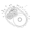
本実施形態における変速機1の構成について、図1〜図3を参照して説明する。変速機1は、車両に搭載される機械式の変速機であって、回転軸に支持された複数の変速ギヤにより前進または後進の変速段を構成している。この変速機1は、図1に示すように、ケース10と、リアリテーナ12と、入力軸20と、出力軸30(本発明の「駆動軸」に相当する)と、ディファレンシャル40と、パーキング機構50を備える。
<Embodiment>
(Configuration of transmission 1)
The structure of the transmission 1 in this embodiment is demonstrated with reference to FIGS. The transmission 1 is a mechanical transmission mounted on a vehicle, and constitutes a forward or reverse shift stage by a plurality of transmission gears supported by a rotating shaft. As shown in FIG. 1, the transmission 1 includes a
ケース10は、複数の軸受けにより回転軸を支承するとともに、回転軸に配置された複数のギヤおよびパーキング機構50を収容している。このケース10は、アーム部11と、リアリテーナ12を有する。アーム部11は、パーキング機構50に向かって延びるようケース10の内周側に設けられている。このアーム部11は、図3に示すように、回転軸方向に貫通した貫通孔11aを形成されている。リアリテーナ12は、ケース10の開口部を覆蓋する蓋部材であって、ボルト締結されてケース10に固定される。また、このリアリテーナ12は、変速機1の内側に面する内側面に、回転軸の軸方向に延びる円筒状の凹部12aが形成されている。
The
入力軸20は、軸状に形成され、軸受によりケース10に回転可能に支持された回転軸である。この入力軸20は、図示しないクラッチ機構を介して車両の駆動源であるエンジンと連結され、駆動力を入力される。また、入力軸20は、図1に示すように、複数の変速段を構成するギヤ対のうち、入力ギヤ21を含む入力側の変速ギヤを支持している。入力ギヤ21は、入力軸20の外周面に形成された外歯スプラインに圧入され、出力軸30に支持された出力側の変速ギヤと噛合することにより所定の変速段を構成している。
The
出力軸30は、軸状に形成され、軸受によりケース10に回転可能に支持された回転軸である。出力軸30は、図1に示すように、複数の変速段を構成するギヤ対のうち、出力ギヤ31を含む出力側の変速ギヤを支持している。そして、出力軸30は、ディファレンシャル40を介して所定の変速段により変速された駆動力を出力する。出力ギヤ31は、出力軸30に対して相対回転可能に支持され、入力軸20に支持された入力側の変速ギヤと噛合している。そして、出力ギヤ31は、図示しないシフト機構によって、選択的に出力軸30と連結されて、入力側の変速ギヤとともに所定の変速段を構成する。
The
ディファレンシャル40は、車両における差動装置である。ディファレンシャル40は、図1に示すように、最終駆動ギヤ41と、リングギヤ42を有する。最終駆動ギヤ41は、出力軸30の外周面に形成された外歯スプラインに圧入され、出力軸30に対して連結固定されている。リングギヤ42は、ケース10に対して回転可能に支持され、図示しないドライブシャフトなどを介して駆動輪に連結され、駆動輪の回転と連動する。また、このリングギヤ42は、最終駆動ギヤ41と常時噛合し、出力軸30に回転連結されている状態となっている。
The differential 40 is a differential device in a vehicle. As shown in FIG. 1, the differential 40 includes a
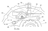
パーキング機構50は、車両が停止した際に駆動軸である出力軸30の回転を規制することにより、出力軸30に回転連結されたリングギヤと連動する駆動輪の回転を規制し、車両の停車状態を保持する機構である。パーキング機構50は、主として、パーキングギヤ51と、マニュアルシャフト52と、マニュアルバルブレバー53と、ロッド54と、カム55と、カムスプリング56と、パーキングポール57と、ポール支持シャフト58と、一対のトーションスプリング61,62と、スプリング支持シャフト63とから構成される。
The
パーキングギヤ51は、外周面に複数の外歯が形成され、出力軸30の外周面に形成された外歯スプラインに圧入されて出力軸30に固定されている。マニュアルシャフト52は、図1に示すように、変速機1の上下方向に延びる軸状部材であって、ケース10に回転可能に支持されている。このマニュアルシャフト52は、車両のシフト位置に応じた角度となるように中心軸回りに回転される。マニュアルバルブレバー53は、マニュアルシャフト52の下部において、マニュアルシャフト52の中心軸に対して垂直に固定される。このような構成により、マニュアルバルブレバー53は、マニュアルシャフト52の回転に連動して一体的に回転する。
The
ロッド54は、変速機1の駆動軸と平行な方向(図1,2の前後方向、図3の左右方向)に延びる軸状部材であって、その一端をマニュアルバルブレバー53に対して揺動可能に連結されている。これにより、ロッド54は、連結されたマニュアルバルブレバー53の回転に伴い、ロッド54の延伸方向に移動することになる。また、ロッド54は、図3に示すように、外周面から径方向に突起した環状のストッパ54aが形成されている。
The
カム55は、ロッド54の軸方向一側に形成された大径部と、この大径部から軸方向他側に向かって徐々に外径が小さくなるように形成された小径部とを有している。また、カム55は、円筒状の内周面を形成され、当該内周面を挿通するロッド54に摺動可能に設けられている。カムスプリング56は、コイル状の圧縮ばねであって、ロッド54の外周側において、ロッド54のストッパ54aとカム55の間に介在している。このカムスプリング56は、一端部をストッパ54aに固定され、他端部をカム55に固定されている。これにより、カム55は、カムスプリング56が無負荷の状態ではカムスプリング56の自由長さによりストッパ54aとの距離を維持されている。
The
パーキングポール57は、図2に示すように、ポール支持シャフト58を介してケース10に回転可能に支持され、回転軸の径方向に延びるように形成されている。また、パーキングポール57の軸方向位置は、ケース10におけるパーキングギヤ51の軸方向位置と一致するように設定されている。このパーキングポール57は、長手方向中央部の外周面において出力軸30に向かって突起し、パーキングギヤ51の外周面に形成された外歯と係止可能な係止爪57aが形成されている。
As shown in FIG. 2, the
パーキングポール57は、ポール支持シャフト58を回転軸として一方側に回転すると、係止爪57aがパーキングギヤ51に係止して駆動軸である出力軸の回転を規制する係止位置に移動する。さらに、パーキングポール57は、ポール支持シャフト58を回転軸として他方側に回転すると、係止爪57aがパーキングギヤ51から離脱して出力軸30の回転を許容する係止解除位置に移動する。このように、パーキングポール57は、ポール支持シャフト58を回転軸とした回転に伴い、上記の規制位置と係止解除位置との間で回転移動する係止部材である。ポール支持シャフト58は、ケース10に支持された軸状部材であって、外周面においてパーキングポール57を支持している。
When the
一対のトーションスプリング61,62は、コイル部61a,62aを形成され、このコイル部61a,62bの周方向に弾性力を有する付勢部材である。本実施形態において、トーションスプリング61とトーションスプリング62の弾性力は、互いに等しく、また全体として必要な弾性力となるように設定されている。また、トーションスプリング61,62は、一端部がパーキングポール57の先端部の下側(図2,3の下側)に当接するとともに、他端部がケース10に固定されるように配置されている。これにより、一対のトーションスプリング61,62は、パーキングポール57が係止位置から係止解除位置に回転移動する方向(図2,3の上方向)にパーキングポール57を付勢している。
The pair of torsion springs 61 and 62 are
ここで、パーキングポール57は、先端部のうちトーションスプリング61,62に付勢される位置とは反対側の背面部(図2,3の上側の部位)がロッド54またはカム55の外周面に当接している。つまり、パーキングポール57は、その背面部がロッド54またはカム55の外周面のうち小径部と当接している場合には、トーションスプリング61,62の弾性力によって係止解除位置に回転移動することになる。また、パーキングポール57は、その背面部がカム55の外周面のうち大径部と当接している場合には、トーションスプリング61,62の弾性力に抗して係止位置に回転移動することになる。
Here, the
上記の一対のトーションスプリング61,62は、パーキングポール57を基準にパーキングポール57の回転軸方向(図3の左右方向)両側の対称位置においてスプリング支持シャフト63にそれぞれ支持される。このスプリング支持シャフト63は、軸状部63aと、挿入部63bと、鍔部63cと、スナップリング63dを有する。軸状部63aは、変速機1の駆動軸方向に延伸する円筒部材である。また、スプリング支持シャフト63は、図2に示すように、パーキングポール57の回転軸(ポール支持シャフト58の中心軸)から離間してケース10に設けられた支持部材である。
The pair of torsion springs 61 and 62 are respectively supported by the
より詳細には、スプリング支持シャフト63は、図3に示すように、軸状部63aがケース10の内周側に設けられたアーム部11の貫通孔11aを挿通している。これによって、スプリング支持シャフト63は、ケース10のアーム部11によって、一対のトーションスプリング61,62の中間に位置する部位を支持されている。そして、スプリング支持シャフト63は、全体形状としてパーキングポール57を基準に回転軸方向にほぼ対称形状となるように形成されている。そのため、本実施形態においては、スプリング支持シャフト63は、軸方向中央部においてケース10に支持されている。
More specifically, as shown in FIG. 3, in the
また、スプリング支持シャフト63の軸状部63aは、トーションスプリング61のコイル部61aおよびトーションスプリング62のコイル部62bの内周側を挿通して、トーションスプリング61,62を同軸上に支持している。また、スプリング支持シャフト63の挿入部63bは、軸状部63aの一側(図3の左側)の端部に形成された部位である。この挿入部63bは、リアリテーナ12の内側面に形成された凹部12aの内径よりも僅かに小さい外径に設定され、当該凹部12aに挿入される。これにより、リアリテーナ12は、スプリング支持シャフト63における一側の端部を支持している。
Further, the shaft-
スプリング支持シャフト63の鍔部63cは、軸状部63aの他側(図3の右側)の端部に形成され、軸状部63aの外周面から径方向に突出した環状の部位である。鍔部63cは、軸状部63aが支持するトーションスプリング62を抜け止めしている。また、スプリング支持シャフト63のスナップリング63dは、軸状部63aの軸方向中央部の近傍の外周面に形成された環状溝に嵌め込まれ、スプリング支持シャフト63の軸方向移動を規制する規制部材である。より詳細には、スナップリング63dは、スプリング支持シャフト63がケース10のアーム部11に支持された状態でアーム部11の回転軸方向一側(図3の左側)の端面に当接する。これにより、スプリング支持シャフト63の軸方向他側(図3の右側)への移動を規制している。
The
このような構成により、一対のトーションスプリング61,62のうち鍔部63c側に配置されたトーションスプリング62は、ケース10のアーム部11と鍔部63cの間に介在することになる。また、一対のトーションスプリング61,62のうちリアリテーナ12側に配置されたトーションスプリング61は、挿入部63bが挿入されたリアリテーナ12とスナップリング63dの間に介在することになる。これにより、パーキングポール57は、一対のトーションスプリング61,62の各一端部により回転軸方向に対象な部位を付勢される。
With such a configuration, the
(変速機1のパーキング機構50の動作)
このような構成からなるパーキング機構50の動作について説明する。上述したように、パーキングポール57は、一対のトーションスプリング61,62によって係止位置から係止解除位置に回転移動する方向に常に付勢されている。そして、例えば、運転者により車両のシフトがPレンジに操作されると、マニュアルシャフト52が所定角度だけ回転される。そうすると、マニュアルバルブレバー53が回転し、これに伴いロッド54が連動して軸方向の一方側に移動する。そして、ロッド54の軸方向移動により、カム55がパーキングポール57の背面部を押圧する状態となる。この時、パーキングギヤ51が係止爪57aと係止可能な位相にある場合には、トーションスプリング61,62の弾性力に抗してパーキングポール57が係止位置に回転移動し、パーキングギヤ51の回転を規制する。これにより、パーキング機構50はロック状態となる。
(Operation of the
The operation of the
また、パーキングギヤ51が係止爪57aと係止できない位相にある場合には、係止爪57aがパーキングギヤ51の外歯の歯先面に当接した状態にある。そうすると、カム55にロッド54のストッパ54aが近接してカムスプリング56が圧縮される。続いて、傾斜面などの影響によって車両に前後力が加えられると駆動輪が回転し、パーキングギヤ51が係止爪57aと係止可能な位相まで回転する。そうすると、カムスプリング56により付勢されたカム55がパーキングポール57の背面部を押圧し、パーキングポール57が係止位置に回転移動する。このように、パーキング機構50は、パーキングギヤ51にパーキングポール57の係止爪57aを係止することにより、駆動軸の回転を規制するロック状態となり、車両の停車状態を維持している。
Further, when the
その後に、車両のシフトがPレンジから他のレンジに操作されると、マニュアルシャフト52が所定角度だけ逆方向に回転される。そうすると、マニュアルバルブレバー53が回転し、これに伴いロッド54が連動して軸方向の他方側に移動する。そして、ロッド54の軸方向移動により、カム55がパーキングポール57の背面部を押圧しない状態となる。そうすると、トーションスプリング61,62の弾性力によってパーキングポール57が係止解除位置に回転移動し、パーキング機構50は、パーキングギヤ51および駆動軸の回転を許容するアンロック状態となる。
Thereafter, when the shift of the vehicle is operated from the P range to another range, the
(変速機1による効果)
上述した構成からなるパーキング機構50を備える変速機1によると、以下の効果を奏する。本実施形態において、一対のトーションスプリング61,62は、パーキングポール57を基準にパーキングポール57の回転軸方向両側の対称位置においてスプリング支持シャフト63に支持される。これにより、一対のトーションスプリング61,62は、全体として必要な弾性力を有するように設定できる。そうすると、各トーションスプリング61,62は、個々の弾性力を低く設定することができる。よって、トーションスプリング61,62は、パーキング機構50の動作に要する弾性力を有しながら、従来のように単数の付勢部材で必要な弾性力を賄う構成や複数箇所に付勢部材を並列に配置する構成と比較して、変速機1における駆動軸の径方向に小型化が可能となる。
(Effects of transmission 1)
The transmission 1 including the
また、パーキング機構50を組み付ける際に、一対のトーションスプリング61,62を個々に配置することができるので、それぞれの組み付けで必要とされる負荷が小さくなり組み付け性を向上できる。さらに、一対のトーションスプリング61,62を支持するスプリング支持シャフト63は、パーキングポール57の回転軸から離間して設けられている。これにより、トーションスプリング61,62がパーキングポール57を付勢する位置をパーキングポール57の回転軸から離間した位置にできるので、比較的低い弾性力に設定することができる。
Further, since the pair of torsion springs 61 and 62 can be individually arranged when the
また、本実施形態において、スプリング支持シャフト63は、ケース10のアーム部11によって、一対のトーションスプリング61,62の中間に位置する部位を支持される構成とした。ここで、従来のパーキング機構において、付勢部材を支持する支持部材の両端部をケースにより支持する構成では、支持部材の両端部が位置する部位にボスなどを形成する必要があった。これに対して、本発明では、上記のような構成により、一対のトーションスプリング61,62を配置する際に基準とした位置と、スプリング支持シャフト63がケース10に支持される位置とが回転軸方向で一致することになる。これにより、両端部をボスなどにより支持しなくてもスプリング支持シャフト63を確実に支持することができる。よって、従来のようにボスなどを形成する必要がなく、さらに省スペース化を図ることができる。
In the present embodiment, the
さらに、パーキング機構50は、一対の付勢部材をトーションスプリング61,62とし、そのコイル部61a,62aをスプリング支持シャフト63の軸状部63aに同軸上に支持する構成とした。これにより、従来のように複数の付勢部材を並列配置する構成と比較して、より確実にパーキング機構50を小型化することができる。
Further, the
また、スプリング支持シャフト63は、鍔部63cとスナップリング63dを有する構成とした。つまり、一対のトーションスプリング61,62は、アーム部11を挟んで配置され、アーム部11とリアリテーナ12、またはアーム部11と鍔部63cの間に介在することになる。これにより、一対のトーションスプリング61,62は、バランス良くパーキングポール57を付勢することができるので、動作をより安定させることができる。また、アーム部11がトーションスプリング61,62の中間に位置する部位を常に支持することができるので、より安定してスプリング支持シャフト63をケース10に設けることができる。
The
また、一対のトーションスプリング61,62は、パーキングポール57を基準にパーキングポール57の回転軸方向両側の対称位置に配置されることに加えて、互いに等しい弾性力に設定される構成とした。これにより、一対のトーションスプリング61,62は、パーキング機構50が必要とする合計弾性力を得るために、個々の最大寸法を小さくすることができるので、全体として小型化を図ることができる。さらに、一対のトーションスプリング61,62により、バランス良くパーキングポール57を付勢することができるので、動作の安定化を図ることができる。
Further, the pair of torsion springs 61 and 62 is configured to be set to have the same elastic force in addition to being arranged at symmetrical positions on both sides in the rotation axis direction of the
さらに、スプリング支持シャフト63は、パーキングポール57の回転軸方向一側の端部に形成された挿入部63bをリアリテーナ12の凹部12aに挿入して支持される構成とした。スプリング支持シャフト63は、ケース10に支持されるように設けられるが、その一側の端部をリアリテーナ12により、補助的に支持されることでケース10に対してより確実に固定することができる。よって、スプリング支持シャフト63が一対のトーションスプリング61,62をより確実に支持することができるので、パーキング機構50の動作をより安定させることができる。
Further, the
<実施形態の変形態様>
本実施形態において、一対の付勢部材は、コイル部61a,62aを有するトーションスプリング61,62とした。これに対して、弾性力をもって係止部材であるパーキングポール57を係止位置から係止解除位置に回転移動するように付勢するものであれば、例えばコイルばねや板ばねなどを適用してもよい。また、一対のトーションスプリング61,62は、互いに弾性力が等しくなるように設定されるものとした。これに対して、例えばケース10の内部においてパーキング機構50が配置可能なスペースの制約などを勘案して、不等の弾性力に設定する構成としてもよい。
<Modification of Embodiment>
In the present embodiment, the pair of urging members are torsion springs 61 and 62 having
また、パーキング機構50のパーキングギヤ51は、駆動軸として出力軸30に固定されるものとした。これに対して、その他の回転軸、例えば入力軸20などに固定する構成としてもよい。さらに、変速機が複数の入力軸および複数の出力軸を選択的に切換えて変速を行うデュアルクラッチ式の場合においても、何れの回転軸にパーキングギヤ51を設ける構成としてもよい。但し、何れの回転軸にパーキングギヤ51を設ける構成としても、車両のシフトがPレンジに操作された際に、パーキングギヤ51が固定された回転軸が駆動輪の回転と連動するように回転連結されている必要がある。このような構成においても実施形態と同様の効果を奏する。
The
1:変速機、
10:ケース、 11:アーム部、 11a:貫通孔
12:リアリテーナ(蓋部材)、 12a:凹部
20:入力軸、 21:入力ギヤ
30:出力軸(駆動軸)、 31:出力ギヤ
40:ディファレンシャル、 41:最終駆動ギヤ、 42:リングギヤ
50:パーキング機構、 51:パーキングギヤ、 52:マニュアルシャフト
53:マニュアルバルブレバー、 54:ロッド、 54a:ストッパ、 55:カム
56:カムスプリング、 57:パーキングポール(係止部材)、 57a:係止爪
58:ポール支持シャフト
61,62:トーションスプリング(付勢部材)、 61a,62a:コイル部
63:スプリング支持シャフト(支持部材)、 63a:軸状部、 63b:挿入部
63c:鍔部、 63d:スナップリング(規制部材)
1: Transmission,
DESCRIPTION OF SYMBOLS 10: Case, 11: Arm part, 11a: Through-hole 12: Rear retainer (lid member), 12a: Recessed part 20: Input shaft, 21: Input gear 30: Output shaft (drive shaft), 31: Output gear 40: Differential, 41: Final drive gear 42: Ring gear 50: Parking mechanism 51: Parking gear 52: Manual shaft 53: Manual valve lever 54:
Claims (6)
前記ケースに回転可能に支持された駆動軸と、
前記駆動軸に固定されたパーキングギヤと、
前記ケースに回転可能に支持され、前記パーキングギヤに係止して前記駆動軸の回転を規制する係止位置と前記パーキングギヤから離脱して前記駆動軸の回転を許容する係止解除位置との間で回転移動する係止部材と、
前記係止部材の回転軸から離間して前記ケースに設けられた支持部材と、
前記係止部材が前記係止位置から前記係止解除位置に回転移動する方向に前記係止部材を付勢する付勢部材であって、前記係止部材を基準に前記係止部材の回転軸方向両側の対称位置において前記支持部材にそれぞれ支持される一対の前記付勢部材と、
を備える変速機。 Case and
A drive shaft rotatably supported by the case;
A parking gear fixed to the drive shaft;
A locking position that is rotatably supported by the case and is locked to the parking gear to restrict the rotation of the driving shaft, and a locking position that is separated from the parking gear and allows the driving shaft to rotate. A locking member that rotates and moves between,
A support member provided on the case apart from the rotation shaft of the locking member;
An urging member for urging the locking member in a direction in which the locking member rotates from the locking position to the locking release position, the rotation shaft of the locking member being based on the locking member; A pair of urging members respectively supported by the support member at symmetrical positions on both sides in the direction;
A transmission comprising:
前記支持部材は、前記ケースの内周側に設けられたアーム部によって、一対の前記付勢部材の中間に位置する部位を支持されている変速機。 In claim 1,
The support member is a transmission in which a portion located in the middle of the pair of urging members is supported by an arm portion provided on an inner peripheral side of the case.
前記付勢部材は、コイル部を有するトーションスプリングであり、
前記支持部材は、前記コイル部の内周側を挿通して一対の前記付勢部材を同軸上に支持する軸状部を有する変速機。 In claim 2,
The biasing member is a torsion spring having a coil portion,
The transmission includes a shaft-like portion that is inserted through the inner peripheral side of the coil portion and coaxially supports the pair of urging members.
前記軸状部の外周側に設けられ、前記支持部材が前記ケースの前記アーム部に支持された状態で前記アーム部の回転軸方向一側の端面に当接し、前記支持部材の回転軸方向他側への移動を規制する規制部材と、
前記軸状部の回転軸方向他側の端部に形成された環状の鍔部と、
を有する変速機。 In claim 3,
Provided on the outer peripheral side of the shaft-shaped portion, the support member is in contact with the end surface of the arm portion on one side in the rotation axis direction while being supported by the arm portion of the case, and the rotation axis direction of the support member, etc. A regulating member that regulates movement to the side,
An annular flange formed at the end of the axial portion on the other side in the rotational axis direction;
A transmission having
一対の前記付勢部材は、互いに等しい弾性力に設定されている変速機。 In any one of Claims 1-4,
The pair of urging members is a transmission that is set to have the same elastic force.
前記ケースの開口部を覆蓋するとともに、前記支持部材における回転軸方向の何れか一方側の端部を支持する蓋部材をさらに備える変速機。 In any one of Claims 1-5,
The transmission further includes a lid member that covers the opening of the case and supports an end of the support member on either side in the rotation axis direction.
Priority Applications (4)
| Application Number | Priority Date | Filing Date | Title |
|---|---|---|---|
| JP2011199823A JP5738136B2 (en) | 2011-09-13 | 2011-09-13 | transmission |
| US14/343,594 US8950563B2 (en) | 2011-09-13 | 2012-09-11 | Transmission |
| EP12831644.5A EP2757004A1 (en) | 2011-09-13 | 2012-09-11 | Transmission |
| PCT/JP2012/073226 WO2013039074A1 (en) | 2011-09-13 | 2012-09-11 | Transmission |
Applications Claiming Priority (1)
| Application Number | Priority Date | Filing Date | Title |
|---|---|---|---|
| JP2011199823A JP5738136B2 (en) | 2011-09-13 | 2011-09-13 | transmission |
Publications (2)
| Publication Number | Publication Date |
|---|---|
| JP2013060107A JP2013060107A (en) | 2013-04-04 |
| JP5738136B2 true JP5738136B2 (en) | 2015-06-17 |
Family
ID=47883302
Family Applications (1)
| Application Number | Title | Priority Date | Filing Date |
|---|---|---|---|
| JP2011199823A Expired - Fee Related JP5738136B2 (en) | 2011-09-13 | 2011-09-13 | transmission |
Country Status (4)
| Country | Link |
|---|---|
| US (1) | US8950563B2 (en) |
| EP (1) | EP2757004A1 (en) |
| JP (1) | JP5738136B2 (en) |
| WO (1) | WO2013039074A1 (en) |
Families Citing this family (8)
| Publication number | Priority date | Publication date | Assignee | Title |
|---|---|---|---|---|
| US9255640B1 (en) * | 2014-09-03 | 2016-02-09 | E-Aam Driveline Systems Ab | Park lock mechanism |
| JP6460933B2 (en) * | 2015-07-16 | 2019-01-30 | トヨタ自動車株式会社 | Manual shift device for vehicle |
| US10161518B2 (en) * | 2016-10-07 | 2018-12-25 | GM Global Technology Operations LLC | Park control system for a vehicle transmission |
| TWI598523B (en) | 2016-10-14 | 2017-09-11 | 財團法人工業技術研究院 | Axial parking mechanism |
| US9995390B2 (en) * | 2016-11-03 | 2018-06-12 | Ford Global Technologies, Llc | Brake mechanism for hybrid vehicle engine |
| US10495223B2 (en) | 2018-01-11 | 2019-12-03 | GM Global Technology Operations LLC | Shift by wire parking system |
| DE102018202370A1 (en) * | 2018-02-16 | 2019-08-22 | Zf Friedrichshafen Ag | Actuator, parking brake device and transmission with such a parking brake device, and associated assembly method |
| US10914378B2 (en) * | 2019-05-07 | 2021-02-09 | GM Global Technology Operations LLC | Roller-gear shift by wire parking system |
Family Cites Families (9)
| Publication number | Priority date | Publication date | Assignee | Title |
|---|---|---|---|---|
| BE555490A (en) * | 1956-03-12 | |||
| US4487302A (en) * | 1981-04-21 | 1984-12-11 | Nissan Motor Company, Limited | Parking lock arrangement for continuously variable V-belt transmission |
| JP3261390B2 (en) * | 1993-07-20 | 2002-02-25 | 株式会社 神崎高級工機製作所 | Transaxle device with axle locking mechanism |
| US5630339A (en) * | 1995-11-02 | 1997-05-20 | General Motors Corporation | Park mechanism for vehicle transmission |
| WO1997025231A1 (en) * | 1996-01-12 | 1997-07-17 | Aisin Aw Co., Ltd. | Parking device for automatic transmission |
| JP2007326438A (en) * | 2006-06-07 | 2007-12-20 | Jatco Ltd | Parking structure of automatic transmission |
| JP2009143363A (en) * | 2007-12-13 | 2009-07-02 | Toyota Motor Corp | Vehicle locking mechanism |
| JP4752961B2 (en) | 2009-07-13 | 2011-08-17 | マツダ株式会社 | Gearbox parking device |
| JP2012207687A (en) | 2011-03-29 | 2012-10-25 | Aisin Ai Co Ltd | Transmission |
-
2011
- 2011-09-13 JP JP2011199823A patent/JP5738136B2/en not_active Expired - Fee Related
-
2012
- 2012-09-11 WO PCT/JP2012/073226 patent/WO2013039074A1/en not_active Ceased
- 2012-09-11 US US14/343,594 patent/US8950563B2/en not_active Expired - Fee Related
- 2012-09-11 EP EP12831644.5A patent/EP2757004A1/en not_active Withdrawn
Also Published As
| Publication number | Publication date |
|---|---|
| US8950563B2 (en) | 2015-02-10 |
| EP2757004A1 (en) | 2014-07-23 |
| JP2013060107A (en) | 2013-04-04 |
| US20140231212A1 (en) | 2014-08-21 |
| WO2013039074A1 (en) | 2013-03-21 |
Similar Documents
| Publication | Publication Date | Title |
|---|---|---|
| JP5738136B2 (en) | transmission | |
| WO2018173695A1 (en) | Power unit for electrically assisted vehicle | |
| JP4747875B2 (en) | Torque fluctuation absorber | |
| JP2008232186A (en) | Lead screw mechanism | |
| WO2018173697A1 (en) | Power unit for electrically assisted vehicle and assembly method thereof | |
| JP2013036535A (en) | Four-bar linkage mechanism type continuously variable transmission | |
| JP6239768B2 (en) | Power unit variable speed drive | |
| WO2019176771A1 (en) | Parking lock device of vehicle drive device, and vehicle drive device | |
| JP2017166626A (en) | Shaft support structure of drive unit | |
| JP4784363B2 (en) | Parking lock device for transmission | |
| JP2007261358A (en) | Parking lock device for transmission | |
| JP5065127B2 (en) | Saddle-ride type vehicle with forward / reverse switching mechanism | |
| WO2018173696A1 (en) | Power unit for electric vehicle | |
| US8307730B2 (en) | Transmission device | |
| JP2008232262A (en) | Shift operation device for transmission | |
| JP5027038B2 (en) | Forward / reverse switching mechanism | |
| JP6384402B2 (en) | Manual transmission shift device | |
| JP6565457B2 (en) | Manual release mechanism for vehicle parking lock device | |
| JP2018155358A (en) | Actuator and hydraulic control circuit including the same | |
| JP6475769B2 (en) | Brake assembly structure in transmission, transmission and vehicle | |
| JP5065126B2 (en) | Saddle-ride type vehicle with auxiliary transmission | |
| JP2008215572A (en) | Telescopic actuator | |
| JP2011241878A (en) | Operation mechanism of automatic transmission | |
| CN107869580A (en) | Power transmission | |
| JP2025136297A (en) | Vehicle transmission |
Legal Events
| Date | Code | Title | Description |
|---|---|---|---|
| A621 | Written request for application examination |
Free format text: JAPANESE INTERMEDIATE CODE: A621 Effective date: 20140513 |
|
| A711 | Notification of change in applicant |
Free format text: JAPANESE INTERMEDIATE CODE: A711 Effective date: 20140618 |
|
| A521 | Request for written amendment filed |
Free format text: JAPANESE INTERMEDIATE CODE: A821 Effective date: 20140618 |
|
| TRDD | Decision of grant or rejection written | ||
| A01 | Written decision to grant a patent or to grant a registration (utility model) |
Free format text: JAPANESE INTERMEDIATE CODE: A01 Effective date: 20150331 |
|
| A61 | First payment of annual fees (during grant procedure) |
Free format text: JAPANESE INTERMEDIATE CODE: A61 Effective date: 20150421 |
|
| R150 | Certificate of patent or registration of utility model |
Ref document number: 5738136 Country of ref document: JP Free format text: JAPANESE INTERMEDIATE CODE: R150 |
|
| LAPS | Cancellation because of no payment of annual fees |