WO2018173697A1 - Power unit for electrically assisted vehicle and assembly method thereof - Google Patents
Power unit for electrically assisted vehicle and assembly method thereof Download PDFInfo
- Publication number
- WO2018173697A1 WO2018173697A1 PCT/JP2018/008026 JP2018008026W WO2018173697A1 WO 2018173697 A1 WO2018173697 A1 WO 2018173697A1 JP 2018008026 W JP2018008026 W JP 2018008026W WO 2018173697 A1 WO2018173697 A1 WO 2018173697A1
- Authority
- WO
- WIPO (PCT)
- Prior art keywords
- assembly
- reduction
- transmission
- hub
- sub
- Prior art date
Links
Images


Definitions
- a motor and a speed reduction mechanism that decelerates the driving force of the motor and transmits it to the hub case are arranged in parallel in the axial direction for an electric vehicle, in particular, a wheel hub case rotatably supported by the hub shaft.
- the present invention relates to a power unit for an electric auxiliary vehicle and an assembling method thereof.
- axial direction and radial direction refer to an axial direction and a radial direction based on the hub shaft.
- a hub case in a power unit for an electric vehicle is coupled to a bottomed cylindrical hub case main body having one end open and an end wall on the other end rotatably supported by a hub shaft, and an open end of the hub case main body.
- the speed reduction mechanism is arranged near the end wall (that is, the bottom wall) of the hub case body and fixed to the hub case body with a partition plate and a plurality of bolts.
- Patent Document 1 discloses a motor disposed on the side opposite to the mechanism portion (that is, the open end side) and the outside of the motor covered with an end wall member fixed to one end of the hub case body. As is well known in the art.
- the reduction planetary gears are configured by first and second gears arranged coaxially, and the first and second gears are connected to the first and second gears.
- the reduction ring gears are engaged with each other, in that case, it is not easy to assemble the reduction mechanism portion having a relatively large number of parts to the hub case body.
- the present invention has been made in view of such circumstances, and an object of the present invention is to provide a power unit for an electrically assisted vehicle with good assembling workability and maintenance workability while securing a high reduction ratio, and an assembling method thereof. .
- the present invention provides a single hub shaft and a bottomed cylindrical hub case body having one end opened and an end wall on the other end rotatably supported by the hub shaft.
- An end wall member coupled to the one end portion of the hub case main body, a transmission mechanism portion that transmits the pedaling force input from the pedal to the end wall member in a shiftable manner, one end portion opened, and the other end side
- a motor having a bottomed cylindrical motor case with an end wall fixed to the hub shaft; and a speed reduction mechanism that decelerates the driving force of the motor and transmits the motor to the end wall member.
- a carrier and the one end of the motor case A first reduction ring gear coupled to the first gear and a second reduction ring gear provided on the end wall member and meshed with the second gear, and the transmission mechanism portion receives the pedaling force.
- a speed change carrier that is rotatable on the hub shaft, a speed change sun gear that is rotatably supported by the hub shaft, and a state in which the speed change sun gear is fixed to the hub shaft by being interposed between the speed change sun gear and the hub shaft.
- a shift mechanism that can be switched between a rotatable state, a shift planetary gear that is rotatably supported by the shift carrier and meshes with the shift sun gear, a shift ring gear that meshes with the shift planetary gear, and in the fixed state,
- the pedal force input to the speed change carrier is transmitted to the end wall member via the speed change planetary gear and the speed change ring gear, and the speed change carrier in the rotatable state.
- a unidirectional transmission mechanism that transmits the pedaling force input to the end wall member without passing through the speed change planetary gear, the hub shaft, the motor, the reduction sun gear, and
- the first reduction ring gear is configured as a set of motor sub-assies
- the reduction carrier and the reduction planetary gear are configured as a set of reduction mechanism sub-assies
- the speed change except for the speed change sun gear and the shift mechanism is configured as a set of motor sub-assies
- the mechanism portion and the end wall member are configured as a group of transmission mechanism subassemblies, and the one end portion of the hub case body is disposed on the hub shaft of the motor subassembly and the speed reduction mechanism subassembly and the transmission mechanism.
- the speed change sun gear and the shift mechanism include the speed reduction mechanism sub-assembly and the speed change mechanism sub-assembly assembled to the hub shaft of the motor sub-assembly.
- a second feature is that it is configured so that it can be assembled on the hub axle in a state where it is not.
- the present invention is also a method for assembling a power unit for an electric auxiliary vehicle having the first or second feature, wherein the motor sub-assembly, the speed reduction mechanism sub-assembly, and the speed change mechanism sub-assembly are assembled separately.
- the hub case body is disposed on the hub shaft on the side opposite to the transmission mechanism sub-assembly.
- the motor subassembly and the speed reduction mechanism subassembly are housed in the hub case body, the end wall member is coupled to the one end portion of the hub case body, and the end wall portion of the hub case body And a hub case main body assembling step for rotatably attaching to the hub shaft.
- the operation unit capable of switching the shift mechanism based on an operation input from the outside is provided with a shaft of the transmission carrier after the transmission mechanism sub-assembly assembly step is completed.
- a fourth feature is that the hub shaft is mounted at a position adjacent to the outer side in the direction.
- the first reduction ring gear has a ring gear extending portion that extends out of the motor case from the one end portion of the motor case, while the end wall
- the member has an end wall extension part surrounded by the ring gear extension part or surrounding the ring gear extension part, and between the opposed peripheral surfaces of the ring gear extension part and the end wall extension part
- a first reduction ring gear support bearing is provided, and in the transmission mechanism sub-assembly assembly step, the first reduction ring gear support bearing is mounted in advance on one of the opposing peripheral surfaces.
- a motor subassembly, a speed reduction mechanism subassembly, and a transmission mechanism subassembly assembled separately in advance can be sequentially and accurately assembled on a single hub shaft.
- the hub case body can be assembled after the sub-assembly assembly work.
- assembly work, function confirmation work after assembly, defective product check work, etc. can be performed in units of individual subassemblies, so that the assembly workability of the power unit and the maintenance workability for individual subassemblies can be performed as a whole. It becomes good and can greatly contribute to the improvement of work efficiency.
- the hub case after assembling the power unit, can be removed from the power unit by removing the hub case body from the opposite side of the transmission mechanism sub-assembly or by removing the transmission mechanism sub-assembly from the opposite side of the hub case body.
- the reduction planetary gears are configured by the first and second gears arranged coaxially, and the first and second gears are engaged with the first and second gears, respectively. A high reduction ratio can be ensured without enlarging the speed reduction mechanism in the radial direction.
- the speed change mechanism sub-assembly can be assembled after the speed reduction sun gear and the shift mechanism are assembled on the hub shaft after the speed reduction mechanism sub-assembly is assembled on the hub shaft of the motor sub-assembly. it can.
- the motor unit, the speed reduction mechanism sub-assembly, and the speed change mechanism sub-assembly are assembled to the hub axle in this order to obstruct the power unit. It becomes possible to assemble.
- the transmission sun gear and the shift mechanism can be easily assembled on the hub shaft after the speed reduction mechanism sub-assembly assembly process is completed and before the transmission mechanism sub-assembly assembly process.
- the operation unit capable of switching the shift mechanism based on an operation input from the outside is adjacent to the outer side in the axial direction of the transmission carrier after the transmission mechanism sub-assembly assembly process is completed. Since the operation unit is easily assembled to the power unit, the operation unit also serves as a means for preventing the shift carrier (and hence the transmission mechanism) from coming off from the hub shaft. Therefore, the transmission mechanism can be more reliably prevented from coming off with a simple structure.
- the first reduction ring gear has a ring gear extension that extends out of the motor case from one end of the motor case, while the end wall member has an end wall extension. Since the first reduction ring gear support bearing is interposed between the opposed peripheral surfaces of the ring gear extension portion and the end wall extension portion, the first reduction ring gear that is cantilevered with respect to the hub shaft is mounted on the bearing.
- the support rigidity of the first reduction ring gear can be increased by supporting the end wall member via the ring, and the peripheral surface of the ring gear extension is the mounting surface of the bearing.
- the bearing diameter can be easily secured without increasing the diameter.
- the first reduction ring gear support bearing mounted in advance on any one of the opposed peripheral surfaces is connected to either one of the opposed peripheral surfaces. Since it is inserted into the surface, even if the first reduction ring gear support bearing is interposed between the ring gear extension and the end wall member, the connection work between them can be performed without any trouble.
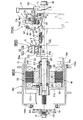
- FIG. 1 is an overall longitudinal sectional view of a power unit for a battery-assisted bicycle according to a first embodiment of the present invention.
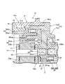
- FIG. 2 is an enlarged view taken along the arrow 2 in FIG.
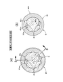
- First embodiment 3 is an enlarged view taken along the line 3 in FIG. 1 (a cross-sectional view taken along line 3-3 in FIG. 4).
- First embodiment 4 shows the locked state of the transmission sun gear with respect to the hub shaft.
- FIG. 4 (A) is a sectional view taken along line 4A-4A in FIG. 3
- FIG. 4 (B) is a sectional view taken along line 4B-4B in FIG. It is.
- (First embodiment) 5A and 5B show the unlocked state of the transmission sun gear with respect to the hub shaft.
- FIG. 1 is an overall longitudinal sectional view of a power unit for a battery-assisted bicycle according to a first embodiment of the present invention.
- FIG. 2 is an enlarged view taken along the arrow 2 in FIG.
- First embodiment 3 is an
- FIG. 5A is a diagram corresponding to FIG. 4A
- FIG. 5B is a diagram corresponding to FIG. It is.
- FIG. 6 is an exploded longitudinal sectional view showing the power unit divided into subassemblies.
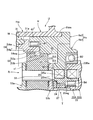
- FIG. 7 is a view corresponding to FIG. 2 showing a second embodiment of the present invention.
- FIG. 8 is a view corresponding to FIGS. 2 and 7 showing a third embodiment of the present invention.
- a power unit U for a power-assisted bicycle which is an example of a power unit for a power-assisted vehicle, functions as a single hub shaft 11 that functions as an axle for supporting a wheel of an electric bicycle, for example, a rear wheel, and a hub portion of a rear wheel.
- a hub case H that is rotatably supported by the hub shaft 11, a transmission mechanism T that is accommodated in the hub case H and that transmits a pedaling force input from the pedal to the hub case H so as to be variable, and a transmission mechanism unit in the hub case H
- a motor drive system MD that is disposed adjacent to T in the axial direction and can drive the hub case H electrically.
- the hub shaft 11 is formed as an integral shaft by forging or machining. Although not shown, both end portions of the hub shaft 11 are inserted and supported by the left and right rear forks, and are coupled and fixed by fastening means such as nuts, as in a conventionally known electric bicycle.
- the hub case H has a bottomed cylindrical hub case body Hm having one end opened and an end wall Hmb integrally formed at the other end, and an annular end detachably coupled to the opened one end Hme of the hub case body Hm.
- a wall member He He.
- the end wall member He has a first end so as to surround the first end wall member half He1 and the first end wall member half He1, for example.
- the second end wall member half body He ⁇ b> 2 is fitted and fixed to the outer peripheral portion of the wall member half body He ⁇ b> 1.
- the outer peripheral portion of the second end wall member half body He2 is inlay-fitted to one end portion Hme of the hub case main body Hm.
- the first and second end wall member halves He1 and He2 may be coupled to each other by an appropriate coupling means, for example, press fitting, welding, screwing, or the like, or may be integrally formed.
- the coupling means of the end wall member He to the hub case main body Hm penetrates the end wall member He (more specifically, the second end wall member half body He2), and the outer periphery of the one end Hme of the hub case main body Hm.
- the end wall member He more specifically, the second end wall member half body He2
- the outer periphery of the one end Hme of the hub case main body Hm can also be adopted.
- a rear wheel spoke (not shown) is fixed to the outer periphery of the hub case body Hm.
- the end wall Hmb of the hub case H is rotatably supported by the hub shaft 11 via the hub supporting first bearing B1 and the end wall member He via the hub supporting second bearing B2.
- the support structure will be described more specifically.
- a hub support ring 15r that holds the hub support first bearing B1 between the inner periphery of the end wall portion Hmb and the hub shaft 11 is supported via a support nut 15n. Is done.
- the support nut 15n fits and supports the inner peripheral portion of the hub support ring 15r.
- the support nut 15n is screwed to the hub shaft 11, and the screwed position is fixed by the lock nut 16.
- the hub shaft 11 has a transmission carrier of the transmission mechanism T that holds the hub supporting second bearing B2 between the inner periphery of the end wall member He (more specifically, the first end wall member half body He1). 22 is rotatably supported via a carrier support bearing B3 as will be described later.
- the hub supporting first and second bearings B1 and B2 are arranged on the radially inner side of the outer diameter of the motor drive system MD (and therefore the motor M) when viewed in a projection plane orthogonal to the hub shaft 11.
- the transmission mechanism T includes a driven sprocket 21 as an input member to which a pedaling force from a pedal is input, a transmission carrier 22 that is coupled to the driven sprocket 21 so as to rotate integrally with the driven sprocket 21, and can rotate on the hub shaft 11.
- the transmission sun gear 23 is rotatably fitted and supported on the outer periphery of the motor 11, and is interposed between the transmission sun gear 23 and the hub shaft 11 so that the transmission sun gear 23 can be switched between a fixed state and a rotatable state on the hub shaft 11.
- the pedal force input to the speed change carrier 22 is transferred to the hub case via the speed change planetary gear 24 and the speed change ring gear 25.
- the pedal treading force is transmitted as a rotational force to the driven sprocket 21 through a chain transmission mechanism including the driven sprocket 21, and the rotational force is transmitted to the transmission carrier 22 and further transmitted to the hub case H through the transmission mechanism T. To drive the rear wheels.
- the transmission carrier 22 is divided into, for example, a cylindrical first carrier half body 22A and a disk-shaped second carrier half body 22B in order to facilitate manufacturing.
- One end 22Aa of the first carrier half 22A integrally has a carrier shaft support wall that supports both ends of the carrier shaft 27, whereby the one end 22Aa is connected to the carrier shaft 27 and the variable planetary gear 24. And supported by the hub shaft 11 via the transmission sun gear 23.
- the carrier support bearing B3 between the inner periphery of the other end 22Ab of the first carrier half body 22A and the outer periphery of the stopper ring 17 that is non-rotatably fitted (for example, press-fitted) to the outer periphery of the hub shaft 11, the carrier support bearing B3.
- the other end 22Ab is rotatably supported by the hub shaft 11 via the carrier supporting bearing B3.
- each inner peripheral portion of the driven sprocket 21 adjacent to the second carrier half 22B is spline fitted to the outer periphery of the first carrier half 22A, and is fixed by a washer 28 and a retaining ring 29.
- first and second carrier halves 22A and 22B may be coupled to each other by other suitable coupling means such as welding, screwing, bonding, or the like, or may be integrally formed.
- a cylindrical carrier extension 22Ba extending toward the motor M is integrally formed on the axial inner side surface of the outer peripheral portion of the second carrier half 22B, and the carrier extension 22Ba is more than the transmission ring gear 25. It is formed in a large diameter cylindrical shape. Between the outer peripheral surface of the carrier extension portion 22Ba and the opposed peripheral surface between the inner periphery of the end wall member He (more specifically, the second end wall member half body He2), the above-described second bearing for hub support is provided. B2 is interposed.
- the transmission ring gear 25 is integrally formed with a ring gear main body portion 25m having an inner tooth 25mg that meshes with the transmission planetary gear 24, and a ring gear extending portion 25a extending from the ring gear main body portion 25m in the opposite direction to the motor drive system MD in the axial direction.
- the ring gear extension 25a is concentrically surrounded by the carrier extension 22Ba. Between the inner circumference of the ring gear extension 25a and the outer circumference of the transmission carrier 22 (more specifically, the one end 22Aa of the first carrier half 22A), a transmission ring gear support bearing B4 is interposed. .
- the one-way transmission mechanism OT is provided between the transmission ring gear 25 and the end wall member He, and can transmit power from the transmission ring gear 25 only to the end wall member He side, and the first one-way clutch C1. Is provided between the speed change carrier 22 and the speed change ring gear 25 at a position shifted in the axial direction, and includes a second one-way clutch C2 capable of transmitting power only from the speed change carrier 22 to the speed change ring gear 25.
- the first one-way clutch C1 is interposed between the opposed peripheral surfaces of the outer periphery of the ring gear main body portion 25m and the inner peripheral boss portion 63 of the first end wall member half body He1, and the second one-way clutch.
- C2 is interposed between opposing peripheral surfaces of the inner periphery of the carrier extension portion 22Ba and the outer periphery of the ring gear extension portion 25a.
- At least a part (most part in the present embodiment) of the second one-way clutch C2 and at least a part (all in the present embodiment) of the transmission ring gear support bearing B4 are in the same position in the axial direction. That is, the arrangement is overlapped in the radial direction. Further, at least a part (all in this embodiment) of the second one-way clutch C2 and at least a part (most part in the present embodiment) of the second hub supporting bearing B2 are in the same position in the axial direction, that is, the diameter. It is an arrangement that overlaps in the direction.
- the first and second one-way clutches C1 and C2 have the same structure as a conventionally well-known one-way clutch structure, and although not shown, for example, any one of the opposing circumferential surfaces of the inner race and the outer race A plurality of engagement grooves provided at intervals on one peripheral surface, and an engaging member (for example, a ratchet claw) that is pivotally supported on one of the other peripheral surfaces so as to be able to engage with and disengage from the engagement groove. And a spring that repels each engaging element in a locking direction with the engaging groove.
- the inner race and the outer race may be separated from the members provided with the first and second one-way clutches C1 and C2, may be retrofitted, or may be formed integrally.
- the outer peripheral surfaces of the ring gear main body portion 25m and the ring gear extending portion 25a which are the attachment surfaces of the first and second one-way clutches C1 and C2 in the transmission ring gear 25, have the same diameter.
- the inner peripheral surface of the inner peripheral boss 63 of the first end wall member half body He1 serving as the mounting surface of the first one-way clutch C1 in the end wall member He and the mounting surface of the second one-way clutch C2 in the transmission carrier 22 are provided.
- the inner peripheral surface of the carrier extension 22Ba has the same diameter. Accordingly, the first and second one-way clutches C1 and C2 can use parts having the same specifications, and cost savings can be achieved by sharing parts.
- the circumferential direction of the engagement element and the engagement groove in the first one-way clutch C1 is the same as that of the second one-way clutch C2. They are set in opposite directions.
- the shift mechanism S includes a plurality of ratchet grooves 23 a that are recessed in the circumferential direction on the inner circumferential surface of the transmission sun gear 23, and a plurality that are recessed in the circumferential direction on the outer circumferential surface of the hub shaft 11.
- the claw 41 is fitted in the outer periphery of the hub shaft 11 in an elastically contracted state and pressed against the outer periphery of the intermediate portion 41m of the ratchet claw 41 so as to constantly urge the claw 41 in the engagement direction with the ratchet groove 23a (ie, the rising direction of the ratchet claw 41).
- the ring spring 42 and a recess 431i in which the tip portion 41bs of the base end portion 41b of the ratchet pawl 41 can protrude and retract are provided on the inner peripheral surface and can be rotated between a predetermined lock position and an unlock position. Then, the operation drum 43 fitted and supported on the outer periphery of the hub shaft 11 and the movable end 44a is provided on the operation drum 43 so as to urge the operation drum 43 to the unlock position (namely, the position of FIG. 5B).
- the operation drum 43 is divided into first and second drum halves 431 and 432. From the outer end of the second drum half 432, a plurality of operating rod portions 432t arranged at intervals in the circumferential direction of the operating drum 43 are integrally extended outward in the axial direction. Each operation lever 432t protrudes outwardly from the speed change carrier 22 through the insertion grooves formed in the inner peripheral surfaces of the fixing ring 46 and the stopper ring 17 respectively.
- the operation lever 432t is linked to an operation plate 71 of an operation unit CU described later, and the operation drum 43 can be rotated between the lock position and the unlock position by the operation unit CU.
- the ratchet pawl 41 released from the operation drum 43 is based on the biasing force of the ring spring 42. Since the state is switched to the latched state in the ratchet groove 23a, the transmission sun gear 23 is connected to the hub shaft 11, that is, in a fixed state and cannot be rotated. As a result, the speed change planetary gear 24 meshed with the speed change sun gear 23 revolves around the speed change carrier shaft 27 while revolving around the hub shaft 11 as the speed change carrier 22 rotates, so that the speed change planet 22 rotates.
- the speed is increased at 24 and transmitted to the transmission ring gear 25, and the increased rotation of the transmission ring gear 25 is transmitted to the end wall member He and thus to the hub case H via the second one-way clutch C ⁇ b> 2.
- the second speed increased from the first speed in the transmission mechanism T is established.
- a unit case CUc of an operation unit CU for switching the shift mechanism S is fixed to the outer periphery of the hub shaft 11 by a nut 18 at a position adjacent to the outer side in the axial direction of the transmission carrier 22.
- an operation plate 71 that can engage with the operation lever portion 432t of the shift mechanism S and can rotate the operation drum 43 is accommodated and supported in a rotatable manner.
- the operation plate 71 is connected to an operation lever 72 that protrudes outside the unit case CUc and can rotate the operation plate 71.
- the operation lever 72 can be remotely operated from the outside. Therefore, the occupant can operate the operation unit CU by hand operation, and by selectively switching the operation drum 43 of the shift mechanism S to either the lock position or the unlock position based on the operation input, the first operation described above is performed.
- the speed change operation between the second speed and the second speed can be arbitrarily performed.
- the motor drive system MD includes an electric motor M and a speed reduction mechanism R that decelerates the driving force of the motor M and transmits it to the end wall member He of the hub case H.
- the motor M includes, for example, a bottomed cylindrical motor case 31 that is open at one end 31 a and faces the end wall member He, a stator 32 that is fixed to the inner peripheral surface of the body portion of the motor case 31, and the radial direction of the stator 32.
- a rotor 33 with a permanent magnet disposed on the inner side and a cylindrical motor shaft 34 for fixing the rotor 33 to the outer peripheral portion are provided.
- the motor shaft 34 is rotatably fitted and supported on the outer periphery of the hub shaft 11 via a pair of motor shaft support first and second bearings B5 and B5 '.
- a boss-like inner peripheral portion of the end wall portion 31b that becomes the bottom wall of the motor case 31 is fitted and fixed to the outer periphery of a boss member 35 that is fitted and fixed to the outer periphery of the hub shaft 11 (press-fit in this embodiment), for example.
- a fixing means for example, combined use of a spline and a retaining ring, screwing or the like
- an electronic control unit ECU for controlling energization to the motor M (more specifically, the coil portion of the stator 32) is attached.
- the wiring extending from the electronic control unit ECU is drawn out through the through hole of the hub support ring 15r. Note that the wiring is connected to a pedaling force detection means, an in-vehicle battery or the like (not shown).
- the reduction mechanism R integrally couples a reduction sun gear 51 that is rotationally driven by the motor M, a first gear 52a that meshes with the reduction sun gear 51, and a second gear 52b that is arranged coaxially with the first gear 52a.
- a second reduction ring gear 55 that meshes with the second gear 52b.
- the reduction sun gear 51 is press-fitted and fixed to the outer periphery of the hub shaft 11 adjacent to a reduction carrier supporting first bearing B6 described later.
- a fixing means of the reduction sun gear 51 a fixing means different from the present embodiment, for example, welding, caulking, adhesion, spline fitting, and a combined use of a retaining ring may be employed.
- the reduction carrier 53 includes a reduction carrier shaft 56 that rotatably penetrates and supports each reduction planetary gear 52, a first carrier half 53a having a first side wall portion s1 that fixes one end of the reduction carrier shaft 56, and A second carrier half 53b having a second side wall portion s2 that sandwiches the reduction planetary gear 52 between the first side wall portion s1 and fixes the other end portion of the reduction carrier shaft 56;
- the first carrier half 53a integrally has a plurality of connecting arm portions 53au, and the tip of the connecting arm portion 53au is fixed to the second carrier half 53b.
- the first side wall portion s1 is connected to the motor shaft 34 (and thus via the motor shaft 34) via the first carrier B6 for speed reduction carrier support interposed between the inner periphery of the first carrier half 53a and the opposed peripheral surface of the motor shaft 34.
- the hub shaft 11) is rotatably supported.
- the second side wall portion s2 is rotatable on the hub shaft 11 via the second carrier B6 ′ for supporting the speed reduction carrier interposed between the inner periphery of the second carrier half 53b and the opposed peripheral surface of the hub shaft 11. Supported.
- a fixing ring 57 for engaging the inner race of the second bearing B 6 ′ for supporting the deceleration carrier and holding the second bearing B 6 ′ (and hence the deceleration carrier 53) on the hub shaft 11. Is inserted (for example, press-fitted).
- the first reduction ring gear 54 is integrally formed with a ring gear main body portion 54m having an inner tooth 54mg that meshes with the first gear 52a and a ring gear extension portion 54a that extends from the ring gear main body portion 54m to the outside of the motor case 31 in the axial direction.
- a ring gear main body portion 54m having an inner tooth 54mg that meshes with the first gear 52a and a ring gear extension portion 54a that extends from the ring gear main body portion 54m to the outside of the motor case 31 in the axial direction.
- the first reduction ring gear 54 is rotated via the hub case H (more specifically, the second end wall member half body He2).
- a first reduction ring gear support bearing B7 to be freely supported is interposed. Accordingly, the inner peripheral surface of the ring gear extending portion 54a becomes the mounting surface on the first reduction ring gear 54 side of the bearing B7.
- the first reduction ring gear 54 is fixed to the motor case 31.
- the reduction planetary gear 52 supported so as to rotate freely rotates around the reduction carrier shaft 56 while revolving around the hub shaft 11. Then, the revolution and rotation of the reduction planetary gear 52 are transmitted from the second gear 52b to the second reduction ring gear 55, so that the rotation of the drive electric motor 4 is transmitted to the hub case H at a high reduction ratio, as will be described later. It becomes possible.
- the second one-way clutch C2 is interposed between the transmission carrier 22 and the transmission ring gear 25, and the first one-way clutch C1 is interposed between the transmission ring gear 25 and the end wall member He. Even when the pedal rotation is slow and the hub case H is fast, the rotation of the hub case H is not transmitted to the pedal side.
- the motor M is energized from the electronic control unit ECU, and the rotation of the motor shaft 34 causes the speed reduction mechanism R to rotate. After that, it is sufficiently decelerated and transmitted to the end wall member He and therefore to the hub case H. As a result, insufficient pedaling force is assisted by the driving force of the motor M, so that it is possible to travel without difficulty even on an uphill.
- the first one-way clutch C1 interposed between the end wall member He and the transmission ring gear 25, and the second one-way clutch C2 interposed between the transmission ring gear 25 and the transmission carrier 22; are arranged in series on the transmission ring gear 25 (more specifically, the outer peripheral surfaces of the transmission ring gear main body 25m and the ring gear extension 25a) at positions shifted in the axial direction, and further between the transmission carrier 22 and the end wall member He.
- the second bearing B2 for supporting the hub interposed between the second one-way clutch C2 and the second one-way clutch C2 is positioned so as to be in the same position in the axial direction (that is, overlaps in the radial direction) with the majority of the second one-way clutch C2.
- the transmission mechanism T is reduced in the axial direction compared to the conventional structure in which the first and second one-way clutches C1 and C2 and the hub supporting second bearing B2 are arranged in the axial direction. Miniaturization of the power unit U is achieved.
- the first and second one-way clutches C1 and C2 are arranged in series on the transmission ring gear 25 as described above, while one end wall portion of the hub case H, that is, the end wall member He is provided from the motor drive system MD.
- a driven portion to which power is input (more specifically, the inner extending portion 62 of the second end wall member half body He2) is provided.
- the driven portion from which the end wall member He receives power includes the driven portion from the motor drive system MD (the inner extending portion 62 of the second end wall member half body He2) and the driven portion from the first one-way clutch C1.
- the transmission ring gear 25 includes a ring gear main body portion 25m having an inner tooth 25mg meshing with the transmission planetary gear 24, and a ring gear extending portion 25a extending axially outward from the ring gear main body portion 25m.
- the clutch C2 is interposed between the outer periphery of the ring gear extension 25a and the inner periphery of the carrier extension 22Ba.
- a transmission ring gear support bearing B4 is interposed between the inner periphery of the ring gear extension 25a and the opposed peripheral surface of the transmission carrier 22, and this transmission ring gear support bearing B4 is a large one of the second one-way clutch C2. Arranged in the same position in the axial direction as the part.
- the transmission ring gear 25 is stably supported on the transmission carrier 22 via the transmission ring gear support bearing B4 even if the transmission ring gear 25 becomes longer in the axial direction due to the series arrangement of the first and second one-way clutches C1 and C2. Therefore, the tooth contact with the speed change planetary gear 24 is good, and the speed change planetary gear 24 can rotate smoothly and quietly.
- the transmission ring gear support bearing B4 since the transmission ring gear support bearing B4 partially overlaps the ring gear extension 25a in the radial direction, the axial extension of the bearing B4 is suppressed, so that the power unit U can be downsized in the axial direction. It is done.
- the reduction planetary gear 52 has first and second gears 52a and 52b arranged coaxially, and the first reduction ring gear 54 meshed with the first gear 52a is a bottomed cylinder.
- the second reduction ring gear 55 fitted to the one end 31a of the motor case 31 and meshed with the second gear 52b is connected to the end wall member He (more specifically, the inner extension of the second end wall member half He2). 62, and a first reduction ring gear support bearing B7 is provided between the first reduction ring gear 54 and the end wall member He (more specifically, the outer periphery of the inner extension 62). Intervened.
- the speed reduction mechanism R has sufficient support rigidity of the first and second speed reduction ring gears 54 and 55 for securing the speed reduction ratio while ensuring a high speed reduction ratio by utilizing the end wall member He. It can be secured.
- the first reduction ring gear 54 is fixed to one end 31 a of the motor case 31, that is, a free end (open end), and is in a cantilevered form with respect to the hub shaft 11.
- the ring gear extension 54a of the reduction ring gear 54 is supported by the end wall member He via the first reduction ring gear support bearing B7, so that the first reduction ring gear 54 is supported in a substantially doubly supported form. Is stable and effective in preventing shaft misalignment. Therefore, even if the rotational vibration of the motor M is directly transmitted to the first reduction ring gear 54, the vibration of the first reduction ring gear 54 can be suppressed as much as possible. Therefore, the first reduction ring gear 54 and the reduction planetary gear 52 (more specifically, the first reduction ring gear 54). It is possible to improve the durability by making the contact of the meshing portion with the 1 gear 52a) good, and to reduce the generation of noise from the meshing portion.
- the one end portion 31a of the motor case 31 is supported on the hub case H side via the first reduction ring gear 54 and the first reduction ring gear support bearing B7. It is not necessary to support the 31a side, and accordingly, there is a space around the hub shaft 11.
- both side walls s1, s2 (first and second carrier halves 53a, 53b) of the speed reduction carrier 53 are connected to the speed reduction carrier supporting first and second bearings B6, B6. Since it is supported on the hub axle 11 via B6 ', the deceleration carrier 53 that is wide in the axial direction can be supported at both ends with a long support span in the axial direction. Thereby, the stable support of the deceleration carrier 53 is achieved, aiming at size reduction of the power unit U.
- the first reduction ring gear 54 of the present embodiment integrally has a ring gear extension 54a that extends in the axial direction from the one end 31a of the motor case 31 to the outside of the motor case 31, and this ring gear extension 54a. Since the peripheral surface is the mounting surface of the first reduction ring gear support bearing B7, a sufficient bearing diameter can be secured without specially increasing the diameter of the motor case 31 itself.
- the power unit U of the present embodiment includes the hub shaft 11, the motor M, the reduction sun gear 51, and the first reduction ring gear 54, among the components.
- the motor subassembly MSA that is, the first assembly block
- the speed reduction carrier 53 and the speed reduction planetary gear 52 in the speed reduction mechanism R are a group of speed reduction mechanism subs.
- Assy RSA ie, the second assembly block
- the speed change mechanism portion T excluding the speed change sun gear 23 and the shift mechanism S and the end wall member He provided with the second reduction ring gear 55 constitute a set of speed change mechanism sub-assemblies TSA (that is, a third assembly block). It can be assembled.
- the speed change sun gear 23 and the shift mechanism S are connected to the hub shaft 11 of the motor subassembly MSA in a state where the speed reduction mechanism subassembly RSA is assembled and the speed change mechanism subassembly TSA is not assembled. It can be assembled on the shaft 11.
- the opening O formed in the one end Hme of the hub case main body Hm is specified by assembling the speed reduction mechanism sub-assembly RSA, the transmission sun gear 23, the shift mechanism S, and the transmission mechanism sub-assembly TSA on the hub shaft 11 of the motor sub-assembly MSA. It is formed in a shape and size that allows passage of the motor sub-assembly MSA and the speed reduction mechanism sub-assembly RSA in the state of assembly.
- the hub case main body Hm is fitted to the hub shaft 11 from the opposite side to the transmission mechanism sub-assembly TSA in the specific assembly stage, and the motor sub-assembly MSA and the speed reduction mechanism sub-assembly RSA are stored in the hub case main body Hm.
- the motor sub-assembly MSA and the speed reduction mechanism sub-assembly RSA interfere with the hub case main body Hm.
- the assembly process of the power unit U of the present embodiment is as follows: Assembling the motor sub-assembly MSA, the speed reduction mechanism sub-assembly RSA, and the speed change mechanism sub-assembly TSA separately as described above (that is, independently of each other) [sub-assembly assembly step]; Next, the first gear 52a in the speed reduction mechanism sub-assembly RSA is simultaneously meshed with the speed reduction sun gear 51 and the first speed reduction ring gear 54 in the motor sub-assembly MSA, and the speed reduction mechanism sub-assembly RSA is attached to the hub shaft 11.
- the hub case body Hm is fitted to the hub shaft 11 from the side opposite to the speed change mechanism sub-assembly TSA, and the motor sub-assembly MSA and the speed reduction mechanism sub-assembly RSA are housed in the hub case main body Hm and one end of the hub case main body Hm.
- the reduction mechanism for the reduction sun gear 51 and the first reduction ring gear 54 of the motor sub-assembly MSA (more specifically, fixed to the motor shaft 34 and the motor case 31).
- the speed reduction mechanism sub-assembly RSA is assembled to the hub shaft 11 while simultaneously engaging the first gear 52a of the sub-assembly RSA.
- the first carrier B6 for supporting the speed reduction carrier has the inner race fixed to the outer periphery of the motor shaft 34 in advance (ie, in the assembly process of the motor subassembly MSA) (for example, press-fitted), and the speed reduction mechanism subassembly RSA is assembled.
- the outer race is mounted on the inner periphery of the first carrier half 53 a of the deceleration carrier 53.
- the second carrier B6 ′ for supporting the speed reduction carrier is fixed (for example, press-fitted) in advance (for example, press-fitted) to the inner circumference of the second carrier half 53b of the speed reduction carrier 53 (that is, in the assembly process of the speed reduction mechanism sub-assembly RSA).
- the inner race is mounted on the outer periphery of the hub shaft 11 simultaneously with the assembly of the mechanism sub-assembly RSA.
- the fixing ring 57 is fixed (for example, press-fitted) to the outer periphery of the hub shaft 11 to prevent the reduction mechanism sub-assembly RSA from coming off.
- the ratchet pawl 41, the ring spring 42, and the transmission sun gear 23 are sequentially set on the outer periphery of the hub shaft 11, and then the first drum half body 431, the return spring 44, and the spring receiving ring 45. And the second drum half 432 are sequentially set, and then the first and second drum halves 431 and 432 are engaged with each other so as not to be relatively rotatable.
- fixing for example, press-fitting
- the transmission planetary gear 24 is used for the transmission sun gear 23, and the transmission mechanism sub-assembly TSA (more specifically, the end wall member He) is used for the second gear 52b.
- the transmission mechanism sub-assembly TSA is assembled to the hub shaft 11 so that the two reduction ring gears 55 are engaged with each other.
- the first reduction ring gear support bearing B7 has, for example, an inner race in advance on the outer periphery of the inner extension 62 as the end wall extension of the end wall member He (that is, in the assembly process of the transmission mechanism sub-assembly TSA).
- the outer race is mounted on the inner periphery of the ring gear extension 54 a of the first reduction ring gear 54 at the same time that the transmission mechanism sub-assembly TSA is assembled.
- the first reduction ring gear support bearing B7 has, for example, an outer race fixed in advance (for example, press-fitted) to the inner periphery of the ring gear extension 54a of the first reduction ring gear 54, and the inner side of the transmission mechanism subassembly TSA is assembled at the same time.
- the race may be attached to the outer periphery of the inner extension 62 of the end wall member He.
- the inner extension 62 itself is used for the inner race
- the ring gear extension 54a itself is used for the outer race, so that the inner extension 62 and the ring gear extension 54a are directly connected between the two 62, 54a.
- the first reduction ring gear support bearing B7 may be configured by a rolling member (for example, a roller or the like) interposed so as to be capable of rolling.
- the [transmission mechanism sub-assembly assembly step] it is fixed (for example, press-fitted) to the inner periphery of the other end 22Ab of the transmission carrier 22 via the carrier support bearing B3 (that is, in the assembly step of the transmission mechanism sub-assembly TSA).
- the inner periphery of the stopper ring 17 is attached to the outer periphery of the hub shaft 11.
- the stopper ring 17 may be mounted between the inner race of the carrier supporting bearing B3 and the outer periphery of the hub shaft 11.
- the bolt case 14 is used to fasten the Hme and He while the one end portion Hme of the hub case body Hm is fitted in the outer periphery of the end wall member He of the transmission mechanism sub-assembly TSA.
- the one end Hme of the hub case main body Hm and the end wall member He of the transmission mechanism sub-assembly TSA may be fastened by other connecting means, for example, spline connection (press-fit) or serration connection.
- the end wall portion Hmb of the hub case main body Hm is attached to the outer periphery of the hub shaft 11 via the first hub support bearing B1, the hub support ring 15r, and the support nut 15n.
- the first hub support bearing B1 has, for example, an outer race fixed in advance (for example, press-fitted) to the inner periphery of the end wall portion Hmb, and the inner ring in accordance with the fitting of the hub support ring 15r to the outer periphery of the hub shaft 11.
- the hub support ring 15r is attached to the race.
- the support nut 15n is screwed to the hub shaft 11, and the hub nut 15n is engaged (ie, concentrically fitted) to the hub support ring 15r.
- 11 is fixed to the support nut 15n and the hub support ring 15r is attached to the support nut 15n.
- an inner race is fixed (for example, press-fitted) to the outer periphery of the hub support ring 15r in advance, and the outer race is matched with the fitting of the hub support ring 15r to the outer periphery of the hub shaft 11. May be mounted on the inner periphery of the end wall Hmb.
- the assembly of the power unit U is temporarily completed. If the motor sub-assembly MSA, the speed reduction mechanism sub-assembly RSA, and the transmission mechanism sub-assembly TSA are assembled to the hub shaft 11 in this order, the power unit U can be assembled without any trouble and efficiently. In addition, after the completion of the [deceleration mechanism sub-assembly assembly step] and before the [transmission mechanism sub-assembly assembly step], the transmission sun gear 23 and the shift mechanism S can be assembled on the hub shaft 11 without any trouble by the above-described work procedure. it can.
- the hub shaft 11 is located at a position where the operation unit CU for the shift mechanism S switching operation is adjacent to the outer side in the axial direction of the transmission carrier 22. Fastened with a nut 18.
- This operation unit assembling step may be executed after the [hub case body assembling step] is completed.
- the operation unit CU fixed to the hub shaft 11 also serves as a means for preventing the transmission carrier 22 (and hence the transmission mechanism portion T) from coming off from the hub shaft 11, the transmission mechanism portion T can be more securely prevented from coming off with a simple structure. Is possible.
- the motor sub-assembly MSA, the speed reduction mechanism sub-assembly RSA, and the speed change mechanism sub-assembly TSA that are individually assembled in advance in separate assembly lines are combined into a single hub shaft.
- the hub case main body Hm can be assembled after the series of sub-assembly assembly operations.
- assembly work, function confirmation work after assembly, defective product check work, etc. can be performed in units of individual sub-assies MSA, RSA, TSA, the assembly workability of the power unit U as a whole, Maintenance workability for the assembly MSA, RSA, TSA is improved, and work efficiency is improved.
- the hub case body Hm is removed from the power unit U from the side opposite to the transmission mechanism sub-assembly TSA, or the transmission mechanism sub-assembly TSA is opposite to the hub case body Hm.
- the hub case body Hm is removed from the power unit U from the side opposite to the transmission mechanism sub-assembly TSA, or the transmission mechanism sub-assembly TSA is opposite to the hub case body Hm.
- the reduction planetary gear 52 is composed of first and second gears 52a and 52b arranged coaxially, and the first and second reduction ring gears 54 and 55 are provided on each of them.
- the number of parts of the speed reduction mechanism R is increased, and in addition, the transmission unit T is also provided in the power unit U and the number of parts is further increased.
- the number of parts increases. Deterioration of assembly workability and maintenance workability can be effectively suppressed by the above-described divided assembly mode in units of subassemblies.
- the first reduction ring gear support bearing B7 includes the outer periphery of the ring gear extension 54a 'of the first reduction ring gear 54 and the inner periphery of the outer extension 61' of the second end wall member half body He2.
- the first embodiment only the outer peripheral surface of the ring gear extension 54a 'and the inner peripheral surface of the outer extension 61' serve as the mounting surface of the first reduction ring gear support bearing B7. It differs from the form.
- the other configuration of the power assisted bicycle power unit U of the second embodiment is the same as that of the power unit U of the first embodiment. Therefore, in FIG. 7, each component is a corresponding component of the first embodiment. Only the same reference numerals are attached, and further description of the structure is omitted. Thus, also in the second embodiment, the same effect as the first embodiment can be expected.
- the power unit U of the second embodiment can also be assembled by the same assembling method as in the first embodiment.
- an annular gap is defined between the opposed peripheral surfaces of the outer extending portions 61 and 61 ′ and the inner extending portions 62 and 62 ′ that protrude from the inner side surface in the axial direction of the end wall member He.
- the ring gear extension portions 54a and 54a 'of the first reduction ring gear 54 are inserted into the annular gap, and the circumferential surfaces of the ring gear extension portions 54a and 54a' facing the annular gap are provided with the first reduction ring gear support bearing B7.
- the mounting surface is provided.
- an inner extending portion 62 ′′ is integrally connected to the inner peripheral side of the outer extending portion 61 ′′ projecting on the inner side surface in the axial direction of the end wall member He to extend the inner side.
- the rigidity of the portion 62 ′′ (and hence the second reduction ring gear 55) is increased, and the extension end of the ring gear extension 54a ′′ of the first reduction ring gear 54 is opposed to the extension end of the inner extension 62 ′′. is doing.
- the other configuration of the power assisted bicycle power unit U of the third embodiment is the same as that of the power unit U of the second embodiment. Therefore, in FIG. 8, each component is a corresponding component of the second embodiment. Only the same reference numerals are attached, and further description of the structure is omitted. Thus, also in the third embodiment, the same operational effects as those in the first and second embodiments can be expected.
- the power unit U of the third embodiment can also be assembled by the same assembling method as in the first embodiment.
- the power unit U is disposed on the rear wheel, but this can also be disposed on the front wheel.
- the vehicle on which the power unit U is mounted is described as a battery-assisted bicycle.
- the power unit of the present invention can also be applied to a stepping-type battery-assisted three-wheeled vehicle.
- the second reduction ring gear 55 is moved from the second reduction ring gear 55 to the hub case H side between the hub case H (end wall member He) and the second reduction ring gear 55.
- a one-way clutch that transmits power only may be arranged.
Abstract
A power unit for an electrically assisted vehicle, wherein a hub shaft (11), a motor (M), a reduction sun gear (51), and a first reduction ring gear (54) are together configured as a motor sub-assembly (MSA), a reduction carrier (53) and a reduction planetary gear (52) are together configured as a reduction mechanism sub-assembly (RSA), and an end wall member (He) and a transmission mechanism (T) excluding a speed-change sun gear (23) and a shift mechanism (S) are together configured as a transmission mechanism sub-assembly (TSA), one end part of a hub case body (Hm) having formed therein an opening (O) through which the sub-assemblies (MSA, RSA) can pass when the reduction mechanism sub-assembly (RSA) and the transmission mechanism sub-assembly (TSA) have been assembled on the hub shaft (11). It is thereby possible to increase assembling workability and maintenance workability while ensuring a high reduction ratio.
Description
本発明は、電動車両用、特にハブ軸に回転可能に支持される車輪のハブケースの内部に、モータと、モータの駆動力を減速してハブケースに伝達する減速機構部とが軸方向に並設される電動補助車両用の動力ユニット及びその組立方法に関する。
In the present invention, a motor and a speed reduction mechanism that decelerates the driving force of the motor and transmits it to the hub case are arranged in parallel in the axial direction for an electric vehicle, in particular, a wheel hub case rotatably supported by the hub shaft. The present invention relates to a power unit for an electric auxiliary vehicle and an assembling method thereof.
尚、本発明及び本明細書において、「軸方向」及び「径方向」は、ハブ軸を基準にした軸方向及び径方向をいう。
In the present invention and the present specification, “axial direction” and “radial direction” refer to an axial direction and a radial direction based on the hub shaft.
電動車両用動力ユニットにおけるハブケースを、一端部が開放され且つ他端側の端壁部がハブ軸に回転可能に支持された有底筒状のハブケース本体と、ハブケース本体の開放端部に結合される端壁部材とで構成し、ハブケース本体の端壁部(即ち底壁部)寄りに減速機構部を配して仕切板及び複数のボルトでハブケース本体に固定し、更にその仕切板の、減速機構部とは反対側(即ち開放端部側)にモータを配して、モータ外側を、ハブケース本体一端部に固定した端壁部材で覆うようにしたものが、例えば、特許文献1に示されるように従来公知である。
A hub case in a power unit for an electric vehicle is coupled to a bottomed cylindrical hub case main body having one end open and an end wall on the other end rotatably supported by a hub shaft, and an open end of the hub case main body. The speed reduction mechanism is arranged near the end wall (that is, the bottom wall) of the hub case body and fixed to the hub case body with a partition plate and a plurality of bolts. For example, Patent Document 1 discloses a motor disposed on the side opposite to the mechanism portion (that is, the open end side) and the outside of the motor covered with an end wall member fixed to one end of the hub case body. As is well known in the art.
上記従来構造では、端壁部材をハブケース本体より取外し、更にハブケース本体よりモータを取り外しても、なお減速機構部はハブケース本体の内奥部に取り残された状態に置かれるため、減速機構部に対する点検整備等のメンテナンス作業を容易には行い得ず、即ち、そのメンテナンス作業のためには、モータの取外し後、減速機構部をハブケース本体の内奥部より取り出す必要がある。従って、全体として動力ユニットのメンテナンスの作業性が良好でない、という問題がある。
In the above conventional structure, even if the end wall member is removed from the hub case body and the motor is further removed from the hub case body, the speed reduction mechanism is still left behind in the hub case body. Maintenance work such as maintenance cannot be performed easily. That is, for the maintenance work, after the motor is removed, it is necessary to take out the speed reduction mechanism from the inner back of the hub case body. Therefore, there is a problem that the workability of maintenance of the power unit is not good as a whole.
ところで遊星歯車式の減速機構部においては、高い減速比を確保するために、減速遊星ギヤを同軸に並ぶ第1,第2ギヤで構成し、その第1,第2ギヤに第1,第2減速リングギヤをそれぞれ噛合させることが考えられるが、その場合には、部品点数が比較的多くなる減速機構部をハブケース本体に組み付ける作業が容易でない。
By the way, in the planetary gear type reduction mechanism unit, in order to ensure a high reduction ratio, the reduction planetary gears are configured by first and second gears arranged coaxially, and the first and second gears are connected to the first and second gears. Although it is conceivable that the reduction ring gears are engaged with each other, in that case, it is not easy to assemble the reduction mechanism portion having a relatively large number of parts to the hub case body.
更にペダルに入力された踏力を変速してハブケースに伝達する変速機構部をハブケースに増設して電動補助車両用動力ユニットとする場合には、部品点数が更に多くなって組立作業性が一層低下する。
Further, when a transmission mechanism that shifts the pedaling force input to the pedal and transmits it to the hub case is added to the hub case to form a power unit for an electrically assisted vehicle, the number of parts is further increased and the assembly workability is further reduced. .
本発明は、かかる事情に鑑みてなされたもので、高い減速比を確保しながら、組立作業性やメンテナンス作業性が良好な電動補助車両用動力ユニット及びその組立方法を提供することを目的とする。
The present invention has been made in view of such circumstances, and an object of the present invention is to provide a power unit for an electrically assisted vehicle with good assembling workability and maintenance workability while securing a high reduction ratio, and an assembling method thereof. .
上記目的を達成するために、本発明は、単一のハブ軸と、一端部が開放され且つ他端側の端壁部が前記ハブ軸に回転可能に支持された有底筒状のハブケース本体と、前記ハブケース本体の前記一端部に結合される端壁部材と、ペダルから入力された踏力を変速可能に前記端壁部材に伝達する変速機構部と、一端部が開放され且つ他端側の端壁部が前記ハブ軸に固定された有底筒状のモータケースを有するモータと、前記モータの駆動力を減速して前記端壁部材に伝達する減速機構部とを備え、前記減速機構部は、前記モータのモータ軸に結合される減速サンギヤと、前記減速サンギヤに噛合する第1ギヤ、及び該第1ギヤに対し同軸に並ぶ第2ギヤを有する減速遊星ギヤを回転自在に支持する減速キャリアと、前記モータケースの前記一端部に結合されて前記第1ギヤに噛合する第1減速リングギヤと、前記端壁部材に設けられて前記第2ギヤに噛合する第2減速リングギヤとを備え、前記変速機構部は、前記踏力が入力され前記ハブ軸上を回転可能な変速キャリアと、前記ハブ軸に回転自在に支持される変速サンギヤと、前記変速サンギヤ及び前記ハブ軸間に介装されて該変速サンギヤを該ハブ軸に対する固定状態と回転可能状態とに切換え可能なシフト機構と、前記変速キャリアに回転可能に支持されて前記変速サンギヤに噛合する変速遊星ギヤと、前記変速遊星ギヤに噛合する変速リングギヤと、前記固定状態では前記変速キャリアに入力された踏力を前記変速遊星ギヤ及び前記変速リングギヤを介して前記端壁部材に伝達させ、また前記回転可能状態では前記変速キャリアに入力された踏力を前記変速遊星ギヤを介さずに前記端壁部材に伝達させる一方向伝動機構とを備える、電動補助車両用動力ユニットであって、前記ハブ軸、前記モータ、前記減速サンギヤ及び前記第1減速リングギヤが、一纏まりのモータサブアッシーとして構成され、前記減速キャリア及び前記減速遊星ギヤが、一纏まりの減速機構サブアッシーとして構成され、前記変速サンギヤ及び前記シフト機構を除いた前記変速機構部と、前記端壁部材とが、一纏まりの変速機構サブアッシーとして構成され、前記ハブケース本体の前記一端部は、前記モータサブアッシーの前記ハブ軸上に前記減速機構サブアッシー及び前記変速機構サブアッシーを組み付けた状態で、前記モータサブアッシー及び前記減速機構サブアッシーが通過可能な開口を有していることを第1の特徴とする。
In order to achieve the above object, the present invention provides a single hub shaft and a bottomed cylindrical hub case body having one end opened and an end wall on the other end rotatably supported by the hub shaft. An end wall member coupled to the one end portion of the hub case main body, a transmission mechanism portion that transmits the pedaling force input from the pedal to the end wall member in a shiftable manner, one end portion opened, and the other end side A motor having a bottomed cylindrical motor case with an end wall fixed to the hub shaft; and a speed reduction mechanism that decelerates the driving force of the motor and transmits the motor to the end wall member. Is a reduction gear that rotatably supports a reduction planetary gear having a reduction sun gear coupled to the motor shaft of the motor, a first gear meshing with the reduction sun gear, and a second gear arranged coaxially with the first gear. A carrier and the one end of the motor case A first reduction ring gear coupled to the first gear and a second reduction ring gear provided on the end wall member and meshed with the second gear, and the transmission mechanism portion receives the pedaling force. A speed change carrier that is rotatable on the hub shaft, a speed change sun gear that is rotatably supported by the hub shaft, and a state in which the speed change sun gear is fixed to the hub shaft by being interposed between the speed change sun gear and the hub shaft. And a shift mechanism that can be switched between a rotatable state, a shift planetary gear that is rotatably supported by the shift carrier and meshes with the shift sun gear, a shift ring gear that meshes with the shift planetary gear, and in the fixed state, The pedal force input to the speed change carrier is transmitted to the end wall member via the speed change planetary gear and the speed change ring gear, and the speed change carrier in the rotatable state. A unidirectional transmission mechanism that transmits the pedaling force input to the end wall member without passing through the speed change planetary gear, the hub shaft, the motor, the reduction sun gear, and The first reduction ring gear is configured as a set of motor sub-assies, the reduction carrier and the reduction planetary gear are configured as a set of reduction mechanism sub-assies, and the speed change except for the speed change sun gear and the shift mechanism. The mechanism portion and the end wall member are configured as a group of transmission mechanism subassemblies, and the one end portion of the hub case body is disposed on the hub shaft of the motor subassembly and the speed reduction mechanism subassembly and the transmission mechanism. With the sub assembly assembled, an opening through which the motor sub assembly and the speed reduction mechanism sub assembly can pass is provided. It has the 1st characteristic to have.
また本発明は、第1の特徴に加えて、前記変速サンギヤ及び前記シフト機構は、前記モータサブアッシーの前記ハブ軸上に前記減速機構サブアッシーが組付けられ且つ前記変速機構サブアッシーが組付けられていない状態で、前記ハブ軸上に組付け可能に構成されることを第2の特徴とする。
Further, according to the present invention, in addition to the first feature, the speed change sun gear and the shift mechanism include the speed reduction mechanism sub-assembly and the speed change mechanism sub-assembly assembled to the hub shaft of the motor sub-assembly. A second feature is that it is configured so that it can be assembled on the hub axle in a state where it is not.
また本発明は、第1又は第2の特徴を有する電動補助車両用動力ユニットの組立方法であって、前記モータサブアッシー、前記減速機構サブアッシー及び前記変速機構サブアッシーを別々に組み立てるサブアッシー組立工程と、前記モータサブアッシーの前記減速サンギヤ及び前記第1減速リングギヤに対し前記第1ギヤを噛合させるようにして、前記ハブ軸に前記減速機構サブアッシーを組み付ける減速機構サブアッシー組付工程と、前記減速機構サブアッシー組付工程の終了後、前記ハブ軸に前記変速サンギヤ及び前記シフト機構を組み付けるシフト機構等組付工程と、前記シフト機構等組付工程の終了後、前記変速サンギヤに対し前記変速遊星ギヤを、また前記第2ギヤに対し前記第2減速リングギヤをそれぞれ噛合させるようにして、前記ハブ軸に前記変速機構サブアッシーを組み付ける変速機構サブアッシー組付工程と、前記変速機構サブアッシー組付工程の終了後、前記ハブケース本体を前記ハブ軸に前記変速機構サブアッシーとは反対側から嵌装して、該ハブケース本体内に前記モータサブアッシー及び前記減速機構サブアッシーを収納すると共に、該ハブケース本体の前記一端部に前記端壁部材を結合し且つ該ハブケース本体の前記端壁部を前記ハブ軸に回転自在に取付けるハブケース本体組付工程と、を少なくとも含むことを第3の特徴とする。
The present invention is also a method for assembling a power unit for an electric auxiliary vehicle having the first or second feature, wherein the motor sub-assembly, the speed reduction mechanism sub-assembly, and the speed change mechanism sub-assembly are assembled separately. And a reduction mechanism sub-assembly assembly step of assembling the reduction mechanism sub-assembly to the hub shaft so as to mesh the first gear with the reduction sun gear and the first reduction ring gear of the motor sub-assembly, After completion of the speed reduction mechanism sub-assembly assembly process, a shift mechanism assembly process for assembling the shift sun gear and the shift mechanism to the hub shaft, and after the shift mechanism assembly process, The transmission planetary gear and the second reduction ring gear mesh with the second gear, respectively. After the transmission mechanism sub-assembly assembly step for assembling the transmission mechanism sub-assembly to the hub shaft and the transmission mechanism sub-assembly assembly step, the hub case body is disposed on the hub shaft on the side opposite to the transmission mechanism sub-assembly. The motor subassembly and the speed reduction mechanism subassembly are housed in the hub case body, the end wall member is coupled to the one end portion of the hub case body, and the end wall portion of the hub case body And a hub case main body assembling step for rotatably attaching to the hub shaft.
また本発明は、第3の特徴に加えて、外部からの操作入力に基づいて前記シフト機構を切換操作可能な操作ユニットが、前記変速機構サブアッシー組付工程の終了後、前記変速キャリアの軸方向外方側に隣接した位置で前記ハブ軸に装着されることを第4の特徴とする。
According to the present invention, in addition to the third feature, the operation unit capable of switching the shift mechanism based on an operation input from the outside is provided with a shaft of the transmission carrier after the transmission mechanism sub-assembly assembly step is completed. A fourth feature is that the hub shaft is mounted at a position adjacent to the outer side in the direction.
また本発明は、第3又は第4の特徴に加えて、前記第1減速リングギヤが、前記モータケースの前記一端部より該モータケース外に延出するリングギヤ延出部を有する一方、前記端壁部材が、前記リングギヤ延出部に囲繞され又は前記リングギヤ延出部を囲繞する端壁延出部を有していて、前記リングギヤ延出部と前記端壁延出部との対向周面間に第1減速リングギヤ支持用軸受が介装されており、前記変速機構サブアッシー組付工程では、前記対向周面のうちの何れか一方の周面に予め装着された前記第1減速リングギヤ支持用軸受が、前記対向周面のうちの何れか他方の周面に挿着されることを第5の特徴とする。
According to the present invention, in addition to the third or fourth feature, the first reduction ring gear has a ring gear extending portion that extends out of the motor case from the one end portion of the motor case, while the end wall The member has an end wall extension part surrounded by the ring gear extension part or surrounding the ring gear extension part, and between the opposed peripheral surfaces of the ring gear extension part and the end wall extension part A first reduction ring gear support bearing is provided, and in the transmission mechanism sub-assembly assembly step, the first reduction ring gear support bearing is mounted in advance on one of the opposing peripheral surfaces. However, it is 5th characteristic that it is inserted by the other peripheral surface of the said opposing peripheral surfaces.
本発明の第1の特徴によれば、予め別々に組立てられたモータサブアッシー、減速機構サブアッシー及び変速機構サブアッシーを、単一のハブ軸上で、精度よく順次組付け可能となり、その一連のサブアッシー組付作業の後でハブケース本体の組付けが可能となる。この場合、個々のサブアッシー単位で、組立作業や組立後の機能確認作業、不良品チェック作業等を行い得ることから、全体として動力ユニットの組立作業性や、個々のサブアッシーに対するメンテナンス作業性が良好となり、作業効率の向上に大いに寄与することができる。しかも動力ユニットの組立後においては、動力ユニットに対し、ハブケース本体を変速機構サブアッシーとは反対側から取り去ることによっても、或いは変速機構サブアッシーをハブケース本体とは反対側から取り去ることによっても、ハブケースを分解して内蔵部品を少なからず外部に露出させることが可能となり、メンテナンスが更に容易となる。その上、動力ユニットの減速機構部においては、減速遊星ギヤを同軸に並ぶ第1,第2ギヤで構成し、第1,第2ギヤに第1,第2減速リングギヤをそれぞれ噛合させることで、減速機構部を径方向に大型化することなく高い減速比を確保可能となる。
According to the first aspect of the present invention, a motor subassembly, a speed reduction mechanism subassembly, and a transmission mechanism subassembly assembled separately in advance can be sequentially and accurately assembled on a single hub shaft. The hub case body can be assembled after the sub-assembly assembly work. In this case, assembly work, function confirmation work after assembly, defective product check work, etc. can be performed in units of individual subassemblies, so that the assembly workability of the power unit and the maintenance workability for individual subassemblies can be performed as a whole. It becomes good and can greatly contribute to the improvement of work efficiency. Moreover, after assembling the power unit, the hub case can be removed from the power unit by removing the hub case body from the opposite side of the transmission mechanism sub-assembly or by removing the transmission mechanism sub-assembly from the opposite side of the hub case body. By disassembling the internal parts, it is possible to expose the built-in parts to the outside, and maintenance becomes easier. In addition, in the speed reduction mechanism portion of the power unit, the reduction planetary gears are configured by the first and second gears arranged coaxially, and the first and second gears are engaged with the first and second gears, respectively. A high reduction ratio can be ensured without enlarging the speed reduction mechanism in the radial direction.
また第2の特徴によれば、モータサブアッシーのハブ軸上に減速機構サブアッシーを組付けた後に変速サンギヤ及びシフト機構をハブ軸上に組付けてから、変速機構サブアッシーを組付けることができる。
According to the second feature, the speed change mechanism sub-assembly can be assembled after the speed reduction sun gear and the shift mechanism are assembled on the hub shaft after the speed reduction mechanism sub-assembly is assembled on the hub shaft of the motor sub-assembly. it can.
また第3の特徴によれば、第1の特徴による上記効果に加えて、モータサブアッシー、減速機構サブアッシー及び変速機構サブアッシーを、この順序でハブ軸に組付けることで、動力ユニットを支障なく組立て可能となる。しかも減速機構サブアッシー組付工程の終了後で且つ変速機構サブアッシー組付工程前に、変速サンギヤ及びシフト機構を容易にハブ軸上に組み付けることができる。
According to the third feature, in addition to the above-described effect of the first feature, the motor unit, the speed reduction mechanism sub-assembly, and the speed change mechanism sub-assembly are assembled to the hub axle in this order to obstruct the power unit. It becomes possible to assemble. Moreover, the transmission sun gear and the shift mechanism can be easily assembled on the hub shaft after the speed reduction mechanism sub-assembly assembly process is completed and before the transmission mechanism sub-assembly assembly process.
また特に第4の特徴によれば、外部からの操作入力に基づいてシフト機構を切換操作可能な操作ユニットが、変速機構サブアッシー組付工程の終了後、変速キャリアの軸方向外方側に隣接した位置でハブ軸に装着されるので、操作ユニットの動力ユニットへの組付作業は容易であり、またこの操作ユニットが、変速キャリア(従って変速機構部)のハブ軸からの抜け止め手段を兼ねることになるため、簡単な構造で変速機構部の一層確実な抜け止めが可能となる。
In particular, according to the fourth feature, the operation unit capable of switching the shift mechanism based on an operation input from the outside is adjacent to the outer side in the axial direction of the transmission carrier after the transmission mechanism sub-assembly assembly process is completed. Since the operation unit is easily assembled to the power unit, the operation unit also serves as a means for preventing the shift carrier (and hence the transmission mechanism) from coming off from the hub shaft. Therefore, the transmission mechanism can be more reliably prevented from coming off with a simple structure.
また特に第5の特徴によれば、第1減速リングギヤが、モータケース一端部よりモータケース外に延出するリングギヤ延出部を有する一方、端壁部材が端壁延出部を有していて、リングギヤ延出部と端壁延出部との対向周面間に第1減速リングギヤ支持用軸受が介装されるので、ハブ軸に対しては片持ち支持となる第1減速リングギヤを、軸受を介して端壁部材にも支持させることで、第1減速リングギヤの支持剛性を高めることができ、しかも、リングギヤ延出部の周面が軸受の取付面となるから、モータケース径を特別に大径化しなくても軸受径を容易に確保可能となる。その上、変速機構サブアッシー組付工程では、上記対向周面のうちの何れか一方の周面に予め装着された第1減速リングギヤ支持用軸受が、対向周面のうちの何れか他方の周面に挿着されるので、リングギヤ延出部と端壁部材間に第1減速リングギヤ支持用軸受が介在しても、その間の接続作業を支障なく行うことができる。
In particular, according to the fifth feature, the first reduction ring gear has a ring gear extension that extends out of the motor case from one end of the motor case, while the end wall member has an end wall extension. Since the first reduction ring gear support bearing is interposed between the opposed peripheral surfaces of the ring gear extension portion and the end wall extension portion, the first reduction ring gear that is cantilevered with respect to the hub shaft is mounted on the bearing. The support rigidity of the first reduction ring gear can be increased by supporting the end wall member via the ring, and the peripheral surface of the ring gear extension is the mounting surface of the bearing. The bearing diameter can be easily secured without increasing the diameter. In addition, in the transmission mechanism sub-assembly assembly step, the first reduction ring gear support bearing mounted in advance on any one of the opposed peripheral surfaces is connected to either one of the opposed peripheral surfaces. Since it is inserted into the surface, even if the first reduction ring gear support bearing is interposed between the ring gear extension and the end wall member, the connection work between them can be performed without any trouble.
B7・・・・第1減速リングギヤ支持用軸受
CU・・・・操作ユニット
He・・・・端壁部材
Hm・・・・ハブケース本体
Hmb・・・端壁部
Hme・・・一端部
M・・・・・モータ
MSA・・・モータサブアッシー
O・・・・・開口
OT・・・・一方向伝動機構
R・・・・・減速機構部
RSA・・・減速機構サブアッシー
S・・・・・シフト機構
T・・・・・変速機構部
TSA・・・変速機構サブアッシー
U・・・・・電動補助自転車用動力ユニット(電動補助車両用動力ユニット)
11・・・・ハブ軸
22・・・・変速キャリア
23・・・・変速サンギヤ
24・・・・変速遊星ギヤ
25・・・・変速リングギヤ
25a・・・リングギヤ延出部
31・・・・モータケース
31a・・・一端部
31b・・・端壁部
51・・・・減速サンギヤ
52・・・・減速遊星ギヤ
52a,52b・・第1,第2ギヤ
53・・・・減速キャリア
54・・・・第1減速リングギヤ
54a,54a′,54a″・・リングギヤ延出部
55・・・・第2減速リングギヤ
61′,61″・・外側延出部(端壁延出部)
62・・・・・・・内側延出部(端壁延出部) B7... First reduction ring gear support bearing CU... Operation unit He... End wall member Hm... Hub case main body Hmb ... end wall portion Hme ... one end M. ... Motor MSA ... Motor sub-assembly O ... Opening OT ... One-way transmission mechanism R ... Deceleration mechanism RSA ... Deceleration mechanism sub-assembly S ... Shift mechanism T ... Transmission mechanism TSA ... Transmission mechanism sub-assembly U ... Power unit for battery-assisted bicycle (Power unit for battery-assisted vehicle)
11 ....Hub shaft 22 .... Speed change carrier 23 ... Speed change sun gear 24 ... Speed change planetary gear 25 ... Speed change ring gear 25a ... Ring gear extension 31 ... Motor Case 31a ... one end 31b ... end wall 51 ... reduction sun gear 52 ... reduction planetary gears 52a, 52b ... first and second gears 53 ... reduction carrier 54 ... .. First reduction ring gears 54a, 54a ', 54a "... Ring gear extension 55 ... Second reduction ring gears 61', 61" ... Outer extension (end wall extension)
62... Inner extension (end wall extension)
CU・・・・操作ユニット
He・・・・端壁部材
Hm・・・・ハブケース本体
Hmb・・・端壁部
Hme・・・一端部
M・・・・・モータ
MSA・・・モータサブアッシー
O・・・・・開口
OT・・・・一方向伝動機構
R・・・・・減速機構部
RSA・・・減速機構サブアッシー
S・・・・・シフト機構
T・・・・・変速機構部
TSA・・・変速機構サブアッシー
U・・・・・電動補助自転車用動力ユニット(電動補助車両用動力ユニット)
11・・・・ハブ軸
22・・・・変速キャリア
23・・・・変速サンギヤ
24・・・・変速遊星ギヤ
25・・・・変速リングギヤ
25a・・・リングギヤ延出部
31・・・・モータケース
31a・・・一端部
31b・・・端壁部
51・・・・減速サンギヤ
52・・・・減速遊星ギヤ
52a,52b・・第1,第2ギヤ
53・・・・減速キャリア
54・・・・第1減速リングギヤ
54a,54a′,54a″・・リングギヤ延出部
55・・・・第2減速リングギヤ
61′,61″・・外側延出部(端壁延出部)
62・・・・・・・内側延出部(端壁延出部) B7... First reduction ring gear support bearing CU... Operation unit He... End wall member Hm... Hub case main body Hmb ... end wall portion Hme ... one end M. ... Motor MSA ... Motor sub-assembly O ... Opening OT ... One-way transmission mechanism R ... Deceleration mechanism RSA ... Deceleration mechanism sub-assembly S ... Shift mechanism T ... Transmission mechanism TSA ... Transmission mechanism sub-assembly U ... Power unit for battery-assisted bicycle (Power unit for battery-assisted vehicle)
11 ....
62... Inner extension (end wall extension)
本発明の実施形態を、添付図面に基づいて以下に説明する。
Embodiments of the present invention will be described below with reference to the accompanying drawings.
先ず、図1~図6に基づいて、本発明の電動補助車両用動力ユニットの第1実施形態を説明する。
First, a first embodiment of a power unit for an electrically assisted vehicle according to the present invention will be described with reference to FIGS.
電動補助車両用動力ユニットの一例である電動補助自転車用動力ユニットUは、電動自転車の車輪、例えば後輪を支持する車軸として機能する単一のハブ軸11と、後輪のハブ部として機能すべくハブ軸11に回転可能に支持されるハブケースHと、ハブケースHに収容されて、ペダルから入力された踏力を変速可能にハブケースHに伝達する変速機構部Tと、ハブケースH内で変速機構部Tに対し軸方向に隣接配置されてハブケースHを電動で駆動し得るモータ駆動系MDとを備える。
A power unit U for a power-assisted bicycle, which is an example of a power unit for a power-assisted vehicle, functions as a single hub shaft 11 that functions as an axle for supporting a wheel of an electric bicycle, for example, a rear wheel, and a hub portion of a rear wheel. A hub case H that is rotatably supported by the hub shaft 11, a transmission mechanism T that is accommodated in the hub case H and that transmits a pedaling force input from the pedal to the hub case H so as to be variable, and a transmission mechanism unit in the hub case H And a motor drive system MD that is disposed adjacent to T in the axial direction and can drive the hub case H electrically.
ハブ軸11は、本実施形態では鍛造又は機械加工により一体物の軸として形成される。ハブ軸11の両端部は、図示はしないが、従来周知の電動自転車と同様に、左右のリヤフォークに嵌挿、支持され、且つナット等の締結手段で結合、固定される。
In the present embodiment, the hub shaft 11 is formed as an integral shaft by forging or machining. Although not shown, both end portions of the hub shaft 11 are inserted and supported by the left and right rear forks, and are coupled and fixed by fastening means such as nuts, as in a conventionally known electric bicycle.
ハブケースHは、一端が開放され且つ他端に端壁部Hmbを一体に有する有底円筒状のハブケース本体Hmと、ハブケース本体Hmの開放された一端部Hmeに着脱可能に結合される環状の端壁部材Heとを備える。
The hub case H has a bottomed cylindrical hub case body Hm having one end opened and an end wall Hmb integrally formed at the other end, and an annular end detachably coupled to the opened one end Hme of the hub case body Hm. A wall member He.
端壁部材Heは、本実施形態では製作加工を容易化するために、例えば円環状の第1端壁部材半体He1と、第1端壁部材半体He1を囲繞するようにして第1端壁部材半体He1の外周部に嵌合、固定される第2端壁部材半体He2とより分割構成される。第2端壁部材半体He2の外周部はハブケース本体Hmの一端部Hmeにインロー嵌合される。第1,第2端壁部材半体He1,He2の相互間は、適当な結合手段、例えば圧入、溶接、螺合等により結合してもよく、或いは一体に形成してもよい。
In this embodiment, the end wall member He has a first end so as to surround the first end wall member half He1 and the first end wall member half He1, for example. The second end wall member half body He <b> 2 is fitted and fixed to the outer peripheral portion of the wall member half body He <b> 1. The outer peripheral portion of the second end wall member half body He2 is inlay-fitted to one end portion Hme of the hub case main body Hm. The first and second end wall member halves He1 and He2 may be coupled to each other by an appropriate coupling means, for example, press fitting, welding, screwing, or the like, or may be integrally formed.
端壁部材Heのハブケース本体Hmへの結合手段は、本実施形態では端壁部材He(より具体的には第2端壁部材半体He2)を貫通してハブケース本体Hmの一端部Hmeの外周ボス部に螺挿される複数のボルト14で構成されるが、その他の適当な結合手段、例えば圧入も採用可能である。ハブケース本体Hmの外周部には、後輪のスポーク(図示せず)が固定される。
In this embodiment, the coupling means of the end wall member He to the hub case main body Hm penetrates the end wall member He (more specifically, the second end wall member half body He2), and the outer periphery of the one end Hme of the hub case main body Hm. Although constituted by a plurality of bolts 14 screwed into the boss portion, other suitable coupling means such as press-fitting can also be adopted. A rear wheel spoke (not shown) is fixed to the outer periphery of the hub case body Hm.
ハブケースHは、これの端壁部Hmbがハブ支持用第1軸受B1を介して、また端壁部材Heがハブ支持用第2軸受B2を介してそれぞれハブ軸11に回転自在に支持される。その支持構造をより具体的に説明すると、ハブ軸11には、ハブ支持用第1軸受B1を端壁部Hmb内周との間で保持するハブ支持リング15rが、支持ナット15nを介して支持される。支持ナット15nは、ハブ支持リング15rの内周部を嵌合、支持するものであって、ハブ軸11に螺合され、その螺合位置はロックナット16で固定される。而して、端壁部Hmbをハブ支持用第1軸受B1及びハブ支持リング15rを介してハブ軸11に支持させる組立工程では、支持ナット15nによりハブ支持用第1軸受B1に対する予圧を調整可能である。
The end wall Hmb of the hub case H is rotatably supported by the hub shaft 11 via the hub supporting first bearing B1 and the end wall member He via the hub supporting second bearing B2. The support structure will be described more specifically. A hub support ring 15r that holds the hub support first bearing B1 between the inner periphery of the end wall portion Hmb and the hub shaft 11 is supported via a support nut 15n. Is done. The support nut 15n fits and supports the inner peripheral portion of the hub support ring 15r. The support nut 15n is screwed to the hub shaft 11, and the screwed position is fixed by the lock nut 16. Thus, in the assembly process in which the end wall Hmb is supported on the hub shaft 11 via the hub support first bearing B1 and the hub support ring 15r, the preload on the hub support first bearing B1 can be adjusted by the support nut 15n. It is.
またハブ軸11には、ハブ支持用第2軸受B2を端壁部材He(より具体的には第1端壁部材半体He1)内周との間で保持する、変速機構部Tの変速キャリア22が、後述するようにキャリア支持用軸受B3を介して回転可能に支持される。
Further, the hub shaft 11 has a transmission carrier of the transmission mechanism T that holds the hub supporting second bearing B2 between the inner periphery of the end wall member He (more specifically, the first end wall member half body He1). 22 is rotatably supported via a carrier support bearing B3 as will be described later.
尚、ハブ支持用第1,第2軸受B1,B2は、ハブ軸11と直交する投影面で見て、モータ駆動系MD(従ってモータM)の外径よりも径方向内方側に配置される。
The hub supporting first and second bearings B1 and B2 are arranged on the radially inner side of the outer diameter of the motor drive system MD (and therefore the motor M) when viewed in a projection plane orthogonal to the hub shaft 11. The
次に変速機構部Tの一例を説明する。変速機構部Tは、ペダルからの踏力が入力される入力部材としての被動スプロケット21と、被動スプロケット21に一体に回転するよう結合されてハブ軸11上を回転可能な変速キャリア22と、ハブ軸11の外周に回転自在に嵌合、支持された変速サンギヤ23と、変速サンギヤ23及びハブ軸11間に介装されて変速サンギヤ23をハブ軸11に固定状態と回転可能状態とに切換え可能な切換手段としてのシフト機構Sと、変速キャリア22に回転可能に支持されて変速サンギヤ23に噛合する複数の変速遊星ギヤ24と、変速遊星ギヤ24に噛合する変速リングギヤ25と、変速サンギヤ23のハブ軸11に対する前記固定状態では変速キャリア22に入力された踏力を変速遊星ギヤ24及び変速リングギヤ25を介してハブケースHの端壁部材Heに伝達させ、また前記回転可能状態では上記踏力を変速遊星ギヤ24を介さずに端壁部材Heに伝達させる一方向伝動機構OTとを備える。
Next, an example of the transmission mechanism T will be described. The transmission mechanism T includes a driven sprocket 21 as an input member to which a pedaling force from a pedal is input, a transmission carrier 22 that is coupled to the driven sprocket 21 so as to rotate integrally with the driven sprocket 21, and can rotate on the hub shaft 11. The transmission sun gear 23 is rotatably fitted and supported on the outer periphery of the motor 11, and is interposed between the transmission sun gear 23 and the hub shaft 11 so that the transmission sun gear 23 can be switched between a fixed state and a rotatable state on the hub shaft 11. A shift mechanism S as switching means, a plurality of transmission planetary gears 24 rotatably supported on the transmission carrier 22 and meshing with the transmission sun gear 23, a transmission ring gear 25 meshing with the transmission planetary gear 24, and a hub of the transmission sun gear 23 In the fixed state with respect to the shaft 11, the pedal force input to the speed change carrier 22 is transferred to the hub case via the speed change planetary gear 24 and the speed change ring gear 25. Is transmitted to the end wall member He, also in the rotatable state and a one-way transmission mechanism OT for transmitting to the end wall member He without via the transmission planetary gear 24 to the pedal force.
被動スプロケット21には、被動スプロケット21を含むチェーン伝動機構を介してペダルの踏力が回転力として伝達され、その回転力が変速キャリア22に伝わり、更に変速機構部Tを介してハブケースHに伝達されて後輪を駆動する。
The pedal treading force is transmitted as a rotational force to the driven sprocket 21 through a chain transmission mechanism including the driven sprocket 21, and the rotational force is transmitted to the transmission carrier 22 and further transmitted to the hub case H through the transmission mechanism T. To drive the rear wheels.
変速キャリア22は、本実施形態では製作加工を容易化するために、例えば円筒状の第1キャリア半体22Aと、円板状の第2キャリア半体22Bとより分割構成される。第1キャリア半体22Aの一端部22Aaは、キャリア軸27の両端部を支持するキャリア軸支持壁部を一体に有しており、これにより、一端部22Aaは、キャリア軸27、変速遊星ギヤ24及び変速サンギヤ23を介してハブ軸11に支持される。一方、第1キャリア半体22Aの他端部22Abの内周と、ハブ軸11外周に相対回転不能に嵌着(例えば圧入)されるストッパリング17の外周との間にはキャリア支持用軸受B3が介装されており、これより、他端部22Abは、キャリア支持用軸受B3を介してハブ軸11に回転自在に支持される。
In this embodiment, the transmission carrier 22 is divided into, for example, a cylindrical first carrier half body 22A and a disk-shaped second carrier half body 22B in order to facilitate manufacturing. One end 22Aa of the first carrier half 22A integrally has a carrier shaft support wall that supports both ends of the carrier shaft 27, whereby the one end 22Aa is connected to the carrier shaft 27 and the variable planetary gear 24. And supported by the hub shaft 11 via the transmission sun gear 23. On the other hand, between the inner periphery of the other end 22Ab of the first carrier half body 22A and the outer periphery of the stopper ring 17 that is non-rotatably fitted (for example, press-fitted) to the outer periphery of the hub shaft 11, the carrier support bearing B3. Thus, the other end 22Ab is rotatably supported by the hub shaft 11 via the carrier supporting bearing B3.
また第1キャリア半体22Aの軸方向中間部の外周には、第2キャリア半体22Bの内周部が圧入により嵌合、固定される。更に第1キャリア半体22Aの外周には、第2キャリア半体22Bに隣接する被動スプロケット21の各内周部がスプライン嵌合され、且つワッシャ28及び止め輪29により固定される。
Further, the inner peripheral portion of the second carrier half body 22B is fitted and fixed to the outer periphery of the intermediate portion in the axial direction of the first carrier half body 22A by press-fitting. Furthermore, each inner peripheral portion of the driven sprocket 21 adjacent to the second carrier half 22B is spline fitted to the outer periphery of the first carrier half 22A, and is fixed by a washer 28 and a retaining ring 29.
尚、被動スプロケット21の固定手段として、止め輪29に代えて、他の適当な固定手段、例えばナットを使用してもよい。尚また、第1,第2キャリア半体22A,22Bの相互は、他の適当な結合手段、例えば溶接、螺合、接着等により結合してもよく、或いは一体に形成してもよい。
In addition, instead of the retaining ring 29, other suitable fixing means, for example, a nut, may be used as the fixing means for the driven sprocket 21. In addition, the first and second carrier halves 22A and 22B may be coupled to each other by other suitable coupling means such as welding, screwing, bonding, or the like, or may be integrally formed.
また第2キャリア半体22Bの外周部の軸方向内側面には、モータM側に延びる円筒状のキャリア延出部22Baが一体に突設され、キャリア延出部22Baは、変速リングギヤ25よりも大径の円筒状に形成される。そして、キャリア延出部22Baの外周と、端壁部材He(より具体的には第2端壁部材半体He2)の内周との対向周面間には、前述のハブ支持用第2軸受B2が介装される。
A cylindrical carrier extension 22Ba extending toward the motor M is integrally formed on the axial inner side surface of the outer peripheral portion of the second carrier half 22B, and the carrier extension 22Ba is more than the transmission ring gear 25. It is formed in a large diameter cylindrical shape. Between the outer peripheral surface of the carrier extension portion 22Ba and the opposed peripheral surface between the inner periphery of the end wall member He (more specifically, the second end wall member half body He2), the above-described second bearing for hub support is provided. B2 is interposed.
変速リングギヤ25は、変速遊星ギヤ24と噛合する内歯25mgを有するリングギヤ本体部25mと、リングギヤ本体部25mから軸方向でモータ駆動系MDとは反対側に延びるリングギヤ延出部25aとを一体に有しており、リングギヤ延出部25aは、キャリア延出部22Baにより同心状に囲繞される。リングギヤ延出部25aの内周と変速キャリア22(より具体的には第1キャリア半体22Aの一端部22Aa)外周との対向周面間には、変速リングギヤ支持用軸受B4が介装される。
The transmission ring gear 25 is integrally formed with a ring gear main body portion 25m having an inner tooth 25mg that meshes with the transmission planetary gear 24, and a ring gear extending portion 25a extending from the ring gear main body portion 25m in the opposite direction to the motor drive system MD in the axial direction. The ring gear extension 25a is concentrically surrounded by the carrier extension 22Ba. Between the inner circumference of the ring gear extension 25a and the outer circumference of the transmission carrier 22 (more specifically, the one end 22Aa of the first carrier half 22A), a transmission ring gear support bearing B4 is interposed. .
次に一方向伝動機構OTの一例を説明する。一方向伝動機構OTは、変速リングギヤ25及び端壁部材He間に設けられて、変速リングギヤ25から端壁部材He側へのみ動力伝達を可能とする第1ワンウェイクラッチC1と、第1ワンウェイクラッチC1とは軸方向にずれた位置で変速キャリア22及び変速リングギヤ25間に設けられて、変速キャリア22から変速リングギヤ25側へのみ動力伝達を可能とする第2ワンウェイクラッチC2とを備える。
Next, an example of the one-way transmission mechanism OT will be described. The one-way transmission mechanism OT is provided between the transmission ring gear 25 and the end wall member He, and can transmit power from the transmission ring gear 25 only to the end wall member He side, and the first one-way clutch C1. Is provided between the speed change carrier 22 and the speed change ring gear 25 at a position shifted in the axial direction, and includes a second one-way clutch C2 capable of transmitting power only from the speed change carrier 22 to the speed change ring gear 25.
特に本実施形態において、第1ワンウェイクラッチC1は、リングギヤ本体部25mの外周と第1端壁部材半体He1の内周ボス部63との対向周面間に介装され、また第2ワンウェイクラッチC2は、キャリア延出部22Baの内周とリングギヤ延出部25aの外周との対向周面間に介装される。
In particular, in the present embodiment, the first one-way clutch C1 is interposed between the opposed peripheral surfaces of the outer periphery of the ring gear main body portion 25m and the inner peripheral boss portion 63 of the first end wall member half body He1, and the second one-way clutch. C2 is interposed between opposing peripheral surfaces of the inner periphery of the carrier extension portion 22Ba and the outer periphery of the ring gear extension portion 25a.
而して、第2ワンウェイクラッチC2の少なくとも一部(本実施形態では大部分)と、変速リングギヤ支持用軸受B4の少なくとも一部(本実施形態では全部)とは軸方向で同一位置にあり、即ち径方向にオーバラップした配置である。また第2ワンウェイクラッチC2の少なくとも一部(本実施形態では全部)と、ハブ支持用第2軸受B2の少なくとも一部(本実施形態では大部分)とは軸方向で同一位置にあり、即ち径方向にオーバラップした配置である。
Thus, at least a part (most part in the present embodiment) of the second one-way clutch C2 and at least a part (all in the present embodiment) of the transmission ring gear support bearing B4 are in the same position in the axial direction. That is, the arrangement is overlapped in the radial direction. Further, at least a part (all in this embodiment) of the second one-way clutch C2 and at least a part (most part in the present embodiment) of the second hub supporting bearing B2 are in the same position in the axial direction, that is, the diameter. It is an arrangement that overlaps in the direction.
第1,第2ワンウェイクラッチC1,C2は、従来周知のワンウェイクラッチ構造と同様の構造を有するものであって、図示はしないが、例えば、インナレース及びアウタレース相互の対向周面のうちの何れか一方の周面に間隔をおいて設けられる複数の係合溝と、その何れか他方の周面に揺動可能に軸支されて係合溝に係脱可能な係合子(例えばラチェット爪)と、各係合子を係合溝との係止方向に弾発するばねとを備える。尚、インナレース及びアウタレースは、第1,第2ワンウェイクラッチC1,C2が設けられる部材と別体、後付けでもよいし、或いは一体に形成してもよい。
The first and second one-way clutches C1 and C2 have the same structure as a conventionally well-known one-way clutch structure, and although not shown, for example, any one of the opposing circumferential surfaces of the inner race and the outer race A plurality of engagement grooves provided at intervals on one peripheral surface, and an engaging member (for example, a ratchet claw) that is pivotally supported on one of the other peripheral surfaces so as to be able to engage with and disengage from the engagement groove. And a spring that repels each engaging element in a locking direction with the engaging groove. The inner race and the outer race may be separated from the members provided with the first and second one-way clutches C1 and C2, may be retrofitted, or may be formed integrally.
また、本実施形態では、変速リングギヤ25における第1,第2ワンウェイクラッチC1,C2の取付面となるリングギヤ本体部25m及びリングギヤ延出部25aの各外周面が同一径である。また端壁部材Heにおける第1ワンウェイクラッチC1の取付面となる第1端壁部材半体He1の内周ボス部63の内周面と、変速キャリア22における第2ワンウェイクラッチC2の取付面となるキャリア延出部22Baの内周面も同一径である。従って、第1,第2ワンウェイクラッチC1,C2は、同一仕様の部品を使用可能となり、部品共通化によるコスト節減が図られる。但し、第1,第2ワンウェイクラッチC1,C2は、動力伝達方向が互いに逆向きであるため、第1ワンウェイクラッチC1における係合子及び係合溝の周方向の向きは、第2ワンウェイクラッチC2のそれとは互いに逆向きに設定される。
In this embodiment, the outer peripheral surfaces of the ring gear main body portion 25m and the ring gear extending portion 25a, which are the attachment surfaces of the first and second one-way clutches C1 and C2 in the transmission ring gear 25, have the same diameter. In addition, the inner peripheral surface of the inner peripheral boss 63 of the first end wall member half body He1 serving as the mounting surface of the first one-way clutch C1 in the end wall member He and the mounting surface of the second one-way clutch C2 in the transmission carrier 22 are provided. The inner peripheral surface of the carrier extension 22Ba has the same diameter. Accordingly, the first and second one-way clutches C1 and C2 can use parts having the same specifications, and cost savings can be achieved by sharing parts. However, since the power transmission directions of the first and second one-way clutches C1 and C2 are opposite to each other, the circumferential direction of the engagement element and the engagement groove in the first one-way clutch C1 is the same as that of the second one-way clutch C2. They are set in opposite directions.
次にシフト機構Sの一例を、主として図3~図5を参照して説明する。
Next, an example of the shift mechanism S will be described mainly with reference to FIGS.
シフト機構Sは、変速サンギヤ23の内周面に周方向に間隔をおいて凹設された複数のラチェット溝23aと、ハブ軸11の外周面に周方向に間隔をおいて凹設された複数の爪収納孔11aと、爪収納孔11aに起伏揺動可能に嵌合、支持され且つその起伏揺動により爪本体部41aの爪先部分41asがラチェット溝23aに係脱し得るラチェット爪41と、ラチェット爪41をラチェット溝23aへの係合方向(即ちラチェット爪41の起立方向)に常時付勢すべくハブ軸11外周に弾性収縮状態で嵌装され且つラチェット爪41の中間部41m外周に圧接するリングばね42と、ラチェット爪41の基端部41bの爪先部分41bsが出没可能な凹部431iを内周面に有すると共に所定のロック位置・アンロック位置間を回動可能としてハブ軸11外周に嵌合支持される操作ドラム43と、操作ドラム43をアンロック位置(即ち図5(B)の位置)側に回動付勢すべく操作ドラム43に可動端44aを係止させる捩じりばねよりなる戻しばね44と、ハブ軸11外周に相対回転不能に嵌着(例えば圧入)されて戻しばね44の固定端44bを係止させるばね受けリング45と、操作ドラム43の外端に隣接配置されてハブ軸11外周に相対回転不能に嵌着(例えば圧入)される操作ドラム抜止め用の固定リング46とを備えている。
The shift mechanism S includes a plurality of ratchet grooves 23 a that are recessed in the circumferential direction on the inner circumferential surface of the transmission sun gear 23, and a plurality that are recessed in the circumferential direction on the outer circumferential surface of the hub shaft 11. A claw storage hole 11a, a ratchet claw 41 which is fitted and supported so as to be able to swing up and down in the claw storage hole 11a, and by which the claw tip portion 41as of the claw body 41a can be engaged and disengaged with the ratchet groove 23a, and a ratchet The claw 41 is fitted in the outer periphery of the hub shaft 11 in an elastically contracted state and pressed against the outer periphery of the intermediate portion 41m of the ratchet claw 41 so as to constantly urge the claw 41 in the engagement direction with the ratchet groove 23a (ie, the rising direction of the ratchet claw 41). The ring spring 42 and a recess 431i in which the tip portion 41bs of the base end portion 41b of the ratchet pawl 41 can protrude and retract are provided on the inner peripheral surface and can be rotated between a predetermined lock position and an unlock position. Then, the operation drum 43 fitted and supported on the outer periphery of the hub shaft 11 and the movable end 44a is provided on the operation drum 43 so as to urge the operation drum 43 to the unlock position (namely, the position of FIG. 5B). A return spring 44 made of a torsion spring to be locked, a spring receiving ring 45 fitted to the outer periphery of the hub shaft 11 so as not to be relatively rotatable (for example, press-fitted) to lock the fixed end 44b of the return spring 44, and an operation drum 43 and a fixing ring 46 for retaining the operation drum, which is disposed adjacent to the outer end of 43 and fitted into the outer periphery of the hub shaft 11 so as not to be relatively rotatable (for example, press-fitted).
操作ドラム43は、第1,第2ドラム半体431,432より分割構成される。第2ドラム半体432の外端からは、操作ドラム43の周方向に間隔をおいて並ぶ複数の操作杆部432tが軸方向外方側に一体に延出している。そして、各操作杆部432tは、固定リング46及びストッパリング17の各内周面にそれぞれ凹設した挿通溝を緩く貫通して変速キャリア22の外方に突出する。操作杆部432tは、後述する操作ユニットCUの作動板71に連係していて、この操作ユニットCUにより操作ドラム43をロック位置・アンロック位置間で回動操作できるようになっている。
The operation drum 43 is divided into first and second drum halves 431 and 432. From the outer end of the second drum half 432, a plurality of operating rod portions 432t arranged at intervals in the circumferential direction of the operating drum 43 are integrally extended outward in the axial direction. Each operation lever 432t protrudes outwardly from the speed change carrier 22 through the insertion grooves formed in the inner peripheral surfaces of the fixing ring 46 and the stopper ring 17 respectively. The operation lever 432t is linked to an operation plate 71 of an operation unit CU described later, and the operation drum 43 can be rotated between the lock position and the unlock position by the operation unit CU.
而して、操作ドラム43が、図5(B)に示すアンロック位置に保持されるときは、操作ドラム43に連動するラチェット爪41の爪本体部41aがリングばね42の付勢力に抗してラチェット溝23aから離脱した状態(即ち爪収納孔11aへの収納状態)におかれる。これにより、変速サンギヤ23がハブ軸11に対し回転可能状態となり、変速遊星ギヤ24も変速サンギヤ23と同様、フリー回転可能である。そのため、踏力に応動した変速キャリア22の回転は、第2ワンウェイクラッチC2、変速リングギヤ25、第1ワンウェイクラッチC1を経て端壁部材He従ってハブケースHに直接(即ち変速遊星ギヤ24を介さずに)伝達される。かくして、変速機構部Tにおいて第1速が確立する。
Thus, when the operation drum 43 is held at the unlock position shown in FIG. 5B, the claw body 41a of the ratchet claw 41 interlocked with the operation drum 43 resists the urging force of the ring spring 42. Thus, it is placed in a state of being detached from the ratchet groove 23a (ie, stored in the claw storage hole 11a). As a result, the transmission sun gear 23 becomes rotatable with respect to the hub shaft 11, and the transmission planetary gear 24 is free to rotate as well as the transmission sun gear 23. Therefore, the rotation of the speed change carrier 22 in response to the pedaling force is directly transmitted to the end wall member He and thus to the hub case H via the second one-way clutch C2, the speed change ring gear 25, and the first one-way clutch C1 (that is, not via the speed change planetary gear 24). Communicated. Thus, the first speed is established in the transmission mechanism T.
それに対し、操作ドラム43が戻しばね44に抗して図4(B)に示すロック位置に保持されるときは、操作ドラム43より解放されたラチェット爪41が、リングばね42の付勢力に基づきラチェット溝23aへの係止状態に切換わるため、変速サンギヤ23がハブ軸11に対し接続即ち固定状態となって回転不能となる。これにより、変速サンギヤ23と噛合する変速遊星ギヤ24が、変速キャリア22の回転に伴いハブ軸11回りを公転しつつ変速キャリア軸27回りを自転するため、変速キャリア22の回転は、変速遊星ギヤ24で増速されて変速リングギヤ25に伝達され、その増速された変速リングギヤ25の回転が第2ワンウェイクラッチC2を経て端壁部材He従ってハブケースHに伝達される。かくして、変速機構部Tにおいて第1速よりも増速された第2速が確立する。
On the other hand, when the operation drum 43 is held at the lock position shown in FIG. 4B against the return spring 44, the ratchet pawl 41 released from the operation drum 43 is based on the biasing force of the ring spring 42. Since the state is switched to the latched state in the ratchet groove 23a, the transmission sun gear 23 is connected to the hub shaft 11, that is, in a fixed state and cannot be rotated. As a result, the speed change planetary gear 24 meshed with the speed change sun gear 23 revolves around the speed change carrier shaft 27 while revolving around the hub shaft 11 as the speed change carrier 22 rotates, so that the speed change planet 22 rotates. The speed is increased at 24 and transmitted to the transmission ring gear 25, and the increased rotation of the transmission ring gear 25 is transmitted to the end wall member He and thus to the hub case H via the second one-way clutch C <b> 2. Thus, the second speed increased from the first speed in the transmission mechanism T is established.
ところでハブ軸11の外周には、シフト機構Sを切換操作するための操作ユニットCUのユニットケースCUcが、変速キャリア22の軸方向外方側に隣接した位置でナット18により固定される。ユニットケースCUc内には、シフト機構Sの操作杆部432tに係合して操作ドラム43を回動操作し得る作動板71が回動可能に収容、支持される。
Incidentally, a unit case CUc of an operation unit CU for switching the shift mechanism S is fixed to the outer periphery of the hub shaft 11 by a nut 18 at a position adjacent to the outer side in the axial direction of the transmission carrier 22. In the unit case CUc, an operation plate 71 that can engage with the operation lever portion 432t of the shift mechanism S and can rotate the operation drum 43 is accommodated and supported in a rotatable manner.
作動板71には、ユニットケースCUc外に張り出して作動板71を回動操作可能な操作レバー72が連結され、操作レバー72は、外部から遠隔操作可能である。従って、乗員は、手元操作で操作ユニットCUを操作でき、その操作入力に基づいてシフト機構Sの操作ドラム43をロック位置・アンロック位置の何れかに選択的に切換えることにより、前述の第1速と第2速の変速切換操作を任意に行うことができる。
The operation plate 71 is connected to an operation lever 72 that protrudes outside the unit case CUc and can rotate the operation plate 71. The operation lever 72 can be remotely operated from the outside. Therefore, the occupant can operate the operation unit CU by hand operation, and by selectively switching the operation drum 43 of the shift mechanism S to either the lock position or the unlock position based on the operation input, the first operation described above is performed. The speed change operation between the second speed and the second speed can be arbitrarily performed.
次にモータ駆動系MDの一例を説明する。モータ駆動系MDは、電動式のモータMと、モータMの駆動力を減速してハブケースHの端壁部材Heに伝達する減速機構部Rとを備える。
Next, an example of the motor drive system MD will be described. The motor drive system MD includes an electric motor M and a speed reduction mechanism R that decelerates the driving force of the motor M and transmits it to the end wall member He of the hub case H.
モータMは、例えば、一端部31aが開放され且つ端壁部材Heに対向する有底円筒状のモータケース31と、モータケース31の胴部内周面に固着したステータ32と、ステータ32の径方向内方側に配置される永久磁石付きロータ33と、ロータ33を外周部に固定する円筒状のモータ軸34とを備える。モータ軸34は、ハブ軸11外周に一対のモータ軸支持用第1,第2軸受B5,B5′を介して回転自在に嵌合、支持される。
The motor M includes, for example, a bottomed cylindrical motor case 31 that is open at one end 31 a and faces the end wall member He, a stator 32 that is fixed to the inner peripheral surface of the body portion of the motor case 31, and the radial direction of the stator 32. A rotor 33 with a permanent magnet disposed on the inner side and a cylindrical motor shaft 34 for fixing the rotor 33 to the outer peripheral portion are provided. The motor shaft 34 is rotatably fitted and supported on the outer periphery of the hub shaft 11 via a pair of motor shaft support first and second bearings B5 and B5 '.
モータケース31の底壁となる端壁部31bの、ボス状をなす内周部は、例えばハブ軸11の外周に嵌合固定(本実施形態では圧入)したボス部材35の外周に嵌合固定(本実施形態ではスプライン圧入)される。尚、本実施形態とは異なる固定手段(例えば、スプラインと止め輪の併用、螺合等)により、端壁部31bの内周部をハブ軸11外周に固定してもよい。
A boss-like inner peripheral portion of the end wall portion 31b that becomes the bottom wall of the motor case 31 is fitted and fixed to the outer periphery of a boss member 35 that is fitted and fixed to the outer periphery of the hub shaft 11 (press-fit in this embodiment), for example. (In this embodiment, spline press-fitting). Note that the inner peripheral portion of the end wall portion 31b may be fixed to the outer periphery of the hub shaft 11 by a fixing means (for example, combined use of a spline and a retaining ring, screwing or the like) different from the present embodiment.
またモータケース31の端壁部31b外面には、モータM(より具体的にはステータ32のコイル部)への通電制御を行う電子制御装置ECUが付設される。電子制御装置ECUから延びる配線は、ハブ支持リング15rの貫通孔を通して外部に引き出される。尚、その配線は、図示しない踏力検出手段や車載バッテリ等に接続される。
Further, on the outer surface of the end wall portion 31b of the motor case 31, an electronic control unit ECU for controlling energization to the motor M (more specifically, the coil portion of the stator 32) is attached. The wiring extending from the electronic control unit ECU is drawn out through the through hole of the hub support ring 15r. Note that the wiring is connected to a pedaling force detection means, an in-vehicle battery or the like (not shown).
次に減速機構部Rの一例を説明する。減速機構部Rは、モータMにより回転駆動される減速サンギヤ51と、減速サンギヤ51に噛合する第1ギヤ52a、及び第1ギヤ52aに対し小径且つ同軸に並ぶ第2ギヤ52bを一体的に結合してなる複数の減速遊星ギヤ52と、減速遊星ギヤ52を回転自在に支持する減速キャリア53と、モータケース31の一端部31aに嵌着されて第1ギヤ52aに噛合する第1減速リングギヤ54と、第2ギヤ52bに噛合する第2減速リングギヤ55とを備える。
Next, an example of the deceleration mechanism R will be described. The reduction mechanism R integrally couples a reduction sun gear 51 that is rotationally driven by the motor M, a first gear 52a that meshes with the reduction sun gear 51, and a second gear 52b that is arranged coaxially with the first gear 52a. A plurality of reduction planetary gears 52, a reduction carrier 53 that rotatably supports the reduction planetary gear 52, and a first reduction ring gear 54 that is fitted to one end 31a of the motor case 31 and meshes with the first gear 52a. And a second reduction ring gear 55 that meshes with the second gear 52b.
減速サンギヤ51は、後述する減速キャリア支持用第1軸受B6に隣接してハブ軸11外周に圧入、固定される。尚、減速サンギヤ51の固定手段としては、本実施形態とは異なる固定手段、例えば溶接、カシメ、接着、スプライン嵌合及び止め輪の併用等を採用してもよい。
The reduction sun gear 51 is press-fitted and fixed to the outer periphery of the hub shaft 11 adjacent to a reduction carrier supporting first bearing B6 described later. In addition, as a fixing means of the reduction sun gear 51, a fixing means different from the present embodiment, for example, welding, caulking, adhesion, spline fitting, and a combined use of a retaining ring may be employed.
減速キャリア53は、各々の減速遊星ギヤ52を回転自在に貫通、支持する減速キャリア軸56と、減速キャリア軸56の一端部を固定する第1側壁部s1を有する第1キャリア半体53aと、第1側壁部s1との間に減速遊星ギヤ52を挟み且つ減速キャリア軸56の他端部を固定する第2側壁部s2を有する第2キャリア半体53bとを備える。第1キャリア半体53aは、複数の連結腕部53auを一体に有しており、連結腕部53auの先部が、第2キャリア半体53bに固定される。
The reduction carrier 53 includes a reduction carrier shaft 56 that rotatably penetrates and supports each reduction planetary gear 52, a first carrier half 53a having a first side wall portion s1 that fixes one end of the reduction carrier shaft 56, and A second carrier half 53b having a second side wall portion s2 that sandwiches the reduction planetary gear 52 between the first side wall portion s1 and fixes the other end portion of the reduction carrier shaft 56; The first carrier half 53a integrally has a plurality of connecting arm portions 53au, and the tip of the connecting arm portion 53au is fixed to the second carrier half 53b.
第1側壁部s1は、第1キャリア半体53aの内周及びモータ軸34の対向周面間に介装した減速キャリア支持用第1軸受B6を介してモータ軸34(従ってモータ軸34を介してハブ軸11)に回転自在に支持される。一方、第2側壁部s2は、第2キャリア半体53bの内周及びハブ軸11の対向周面間に介装した減速キャリア支持用第2軸受B6′を介してハブ軸11に回転自在に支持される。尚、ハブ軸11外周には、減速キャリア支持用第2軸受B6′のインナレースに係合して第2軸受B6′(従って減速キャリア53)をハブ軸11上に保持するための固定リング57が嵌着(例えば圧入)される。
The first side wall portion s1 is connected to the motor shaft 34 (and thus via the motor shaft 34) via the first carrier B6 for speed reduction carrier support interposed between the inner periphery of the first carrier half 53a and the opposed peripheral surface of the motor shaft 34. The hub shaft 11) is rotatably supported. On the other hand, the second side wall portion s2 is rotatable on the hub shaft 11 via the second carrier B6 ′ for supporting the speed reduction carrier interposed between the inner periphery of the second carrier half 53b and the opposed peripheral surface of the hub shaft 11. Supported. On the outer periphery of the hub shaft 11, a fixing ring 57 for engaging the inner race of the second bearing B 6 ′ for supporting the deceleration carrier and holding the second bearing B 6 ′ (and hence the deceleration carrier 53) on the hub shaft 11. Is inserted (for example, press-fitted).
第1減速リングギヤ54は、第1ギヤ52aと噛合する内歯54mgを有するリングギヤ本体部54mと、リングギヤ本体部54mから軸方向でモータケース31外に延出するリングギヤ延出部54aとを一体に有する。
The first reduction ring gear 54 is integrally formed with a ring gear main body portion 54m having an inner tooth 54mg that meshes with the first gear 52a and a ring gear extension portion 54a that extends from the ring gear main body portion 54m to the outside of the motor case 31 in the axial direction. Have.
ところで端壁部材He、特に第2端壁部材半体He2の軸方向内側面には、軸方向内方側に延出してハブケース本体Hm内周に嵌合する円筒状の外側延出部61が一体に突設され、また第2端壁部材半体He2の軸方向内側面の内周部には、軸方向内方側に延出し且つ外側延出部61により同心状に囲繞される円筒状の内側延出部62が一体に突設される。そして、第1減速リングギヤ54のリングギヤ延出部54aが、外側延出部61及び内側延出部62の相互間に画成される環状空隙に突入している。
By the way, on the inner side surface in the axial direction of the end wall member He, particularly the second end wall member half body He2, there is a cylindrical outer extending portion 61 that extends inward in the axial direction and fits into the inner periphery of the hub case body Hm. A cylindrical shape projecting integrally and extending inward in the axial direction and concentrically surrounded by an outer extending portion 61 on the inner peripheral portion of the inner end surface in the axial direction of the second end wall member half body He <b> 2. The inner extending portion 62 is integrally projected. The ring gear extension 54 a of the first reduction ring gear 54 enters an annular gap defined between the outer extension 61 and the inner extension 62.
またリングギヤ延出部54aの内周と内側延出部62の外周との間には、第1減速リングギヤ54をハブケースH(より具体的には第2端壁部材半体He2)を介して回転自在に支持させる第1減速リングギヤ支持用軸受B7が介装される。従って、リングギヤ延出部54aの内周面が上記軸受B7の第1減速リングギヤ54側の取付面となる。
Further, between the inner periphery of the ring gear extension 54a and the outer periphery of the inner extension 62, the first reduction ring gear 54 is rotated via the hub case H (more specifically, the second end wall member half body He2). A first reduction ring gear support bearing B7 to be freely supported is interposed. Accordingly, the inner peripheral surface of the ring gear extending portion 54a becomes the mounting surface on the first reduction ring gear 54 side of the bearing B7.
而して、モータMに駆動される減速サンギヤ51の回転が減速遊星ギヤ52の第1ギヤ52aに伝えられると、第1減速リングギヤ54がモータケース31に固定されていることから、減速キャリア53に回転可能に支持された減速遊星ギヤ52がハブ軸11回りを公転しながら減速キャリア軸56回りに自転する。そして、この減速遊星ギヤ52の公転及び自転が第2ギヤ52bから第2減速リングギヤ55に伝達されることで、後述するように、駆動用電動モータ4の回転をハブケースHに高い減速比で伝達可能となる。
Thus, when the rotation of the reduction sun gear 51 driven by the motor M is transmitted to the first gear 52 a of the reduction planetary gear 52, the first reduction ring gear 54 is fixed to the motor case 31. The reduction planetary gear 52 supported so as to rotate freely rotates around the reduction carrier shaft 56 while revolving around the hub shaft 11. Then, the revolution and rotation of the reduction planetary gear 52 are transmitted from the second gear 52b to the second reduction ring gear 55, so that the rotation of the drive electric motor 4 is transmitted to the hub case H at a high reduction ratio, as will be described later. It becomes possible.
次に、第1実施形態の作用を説明する。電動補助自転車の走行中、搭乗者によるペダルの踏力は、変速機構部Tを介して二段階(第1速又は第2速)に変速されて端壁部材He、従ってハブケースHに伝達される。
Next, the operation of the first embodiment will be described. During the travel of the battery-assisted bicycle, the pedaling force of the pedal by the occupant is shifted in two stages (first speed or second speed) via the speed change mechanism T and transmitted to the end wall member He and thus the hub case H.
例えば、シフト機構Sの操作ドラム43がアンロック位置に在って、変速サンギヤ23とハブ軸11間の接続が解除されているときは、変速キャリア22の回転が第2ワンウェイクラッチC2、変速リングギヤ25、第1ワンウェイクラッチC1を経て直接、端壁部材Heに伝達される。これにより、後輪の一部であるハブケースHが変速キャリア22と同じ回転数で回転する。
For example, when the operation drum 43 of the shift mechanism S is in the unlocked position and the connection between the transmission sun gear 23 and the hub shaft 11 is released, the rotation of the transmission carrier 22 is rotated by the second one-way clutch C2, the transmission ring gear. 25, directly transmitted to the end wall member He via the first one-way clutch C1. As a result, the hub case H that is a part of the rear wheel rotates at the same rotational speed as that of the transmission carrier 22.
一方、シフト機構Sの操作ドラム43がロック位置に在って、変速サンギヤ23がハブ軸11に固定されているときは、変速キャリア22の回転が変速遊星ギヤ24及び変速リングギヤ25を経て増速されて端壁部材Heに伝達される。これにより、ハブケースHが、変速キャリア22の回転に対し増速されて回転する。
On the other hand, when the operation drum 43 of the shift mechanism S is in the locked position and the transmission sun gear 23 is fixed to the hub axle 11, the rotation of the transmission carrier 22 is increased through the transmission planetary gear 24 and the transmission ring gear 25. And transmitted to the end wall member He. As a result, the hub case H rotates at an increased speed relative to the rotation of the transmission carrier 22.
尚、変速キャリア22及び変速リングギヤ25間には第2ワンウェイクラッチC2が、また変速リングギヤ25及び端壁部材He間には第1ワンウェイクラッチC1がそれぞれ介装されるため、例えば、下り坂において、ペダルの回転が遅くハブケースHの回転が速い場合でも、ハブケースHの回転がペダル側に伝達されることはない。
The second one-way clutch C2 is interposed between the transmission carrier 22 and the transmission ring gear 25, and the first one-way clutch C1 is interposed between the transmission ring gear 25 and the end wall member He. Even when the pedal rotation is slow and the hub case H is fast, the rotation of the hub case H is not transmitted to the pedal side.
また、電動補助自転車の走行中、図示しない負荷検出手段により後輪の走行負荷増大が検出されると、電子制御装置ECUからモータMに通電がなされ、モータ軸34の回転が減速機構部Rを経て十分に減速されて端壁部材He従ってハブケースHに伝達される。これにより、踏力不足がモータMの駆動力で補助されるため、例えば、登り坂でも無理なく走行可能となる。
In addition, when an increase in the rear wheel driving load is detected by a load detection means (not shown) during driving of the battery-assisted bicycle, the motor M is energized from the electronic control unit ECU, and the rotation of the motor shaft 34 causes the speed reduction mechanism R to rotate. After that, it is sufficiently decelerated and transmitted to the end wall member He and therefore to the hub case H. As a result, insufficient pedaling force is assisted by the driving force of the motor M, so that it is possible to travel without difficulty even on an uphill.
また本実施形態の変速機構部Tにおいては、端壁部材He及び変速リングギヤ25間に介装した第1ワンウェイクラッチC1と、変速リングギヤ25及び変速キャリア22間に介装した第2ワンウェイクラッチC2とが、互いに軸方向にずれた位置で変速リングギヤ25上(より具体的には変速リングギヤ本体25m及びリングギヤ延出部25aの各外周面)に直列配置され、更に変速キャリア22と端壁部材He間に介装されるハブ支持用第2軸受B2が、第2ワンウェイクラッチC2の大部分と軸方向で同一位置となる(即ち径方向にオーバラップする)ようにして第2ワンウェイクラッチC2の周囲を取り囲む配置となっている。これにより、第1,第2ワンウェイクラッチC1,C2、並びにハブ支持用第2軸受B2の三者が軸方向に並ぶ従来構造に比べて変速機構部Tが軸方向に小型化されるため、それだけ動力ユニットUの小型化が達成される。
In the transmission mechanism T of the present embodiment, the first one-way clutch C1 interposed between the end wall member He and the transmission ring gear 25, and the second one-way clutch C2 interposed between the transmission ring gear 25 and the transmission carrier 22; Are arranged in series on the transmission ring gear 25 (more specifically, the outer peripheral surfaces of the transmission ring gear main body 25m and the ring gear extension 25a) at positions shifted in the axial direction, and further between the transmission carrier 22 and the end wall member He. The second bearing B2 for supporting the hub interposed between the second one-way clutch C2 and the second one-way clutch C2 is positioned so as to be in the same position in the axial direction (that is, overlaps in the radial direction) with the majority of the second one-way clutch C2. Surrounding arrangement. As a result, the transmission mechanism T is reduced in the axial direction compared to the conventional structure in which the first and second one-way clutches C1 and C2 and the hub supporting second bearing B2 are arranged in the axial direction. Miniaturization of the power unit U is achieved.
また第1,第2ワンウェイクラッチC1,C2が、上記のように変速リングギヤ25上に直列配置される一方で、ハブケースHの一端壁部、即ち端壁部材Heには、モータ駆動系MDからの動力が入力される被動部(より具体的には第2端壁部材半体He2の内側延出部62)が設けられる。これにより、端壁部材Heが動力を受ける被動部としては、モータ駆動系MDからの被動部(第2端壁部材半体He2の内側延出部62)と第1ワンウェイクラッチC1からの被動部(第1端壁部材半体He1の内周ボス部63)しかなく、それだけ端壁部材Heの小型化や構造簡素化が図られ、延いては動力ユニットUの小型化が図られる。
The first and second one-way clutches C1 and C2 are arranged in series on the transmission ring gear 25 as described above, while one end wall portion of the hub case H, that is, the end wall member He is provided from the motor drive system MD. A driven portion to which power is input (more specifically, the inner extending portion 62 of the second end wall member half body He2) is provided. As a result, the driven portion from which the end wall member He receives power includes the driven portion from the motor drive system MD (the inner extending portion 62 of the second end wall member half body He2) and the driven portion from the first one-way clutch C1. There is only (the inner peripheral boss portion 63 of the first end wall member half body He1), so that the end wall member He can be reduced in size and structure, and the power unit U can be further reduced in size.
また変速リングギヤ25は、変速遊星ギヤ24と噛合する内歯25mgを有するリングギヤ本体部25mと、リングギヤ本体部25mから軸方向外方に延びるリングギヤ延出部25aとを有しており、第2ワンウェイクラッチC2がリングギヤ延出部25aの外周とキャリア延出部22Baの内周との間に介装される。これにより、第1,第2ワンウェイクラッチC1,C2の軸方向合計幅が変速遊星ギヤ24の歯幅より長くても、両クラッチC1,C2を、互いに軸方向に隣接させた状態で変速リングギヤ25上に無理なく直列配置可能となる。
The transmission ring gear 25 includes a ring gear main body portion 25m having an inner tooth 25mg meshing with the transmission planetary gear 24, and a ring gear extending portion 25a extending axially outward from the ring gear main body portion 25m. The clutch C2 is interposed between the outer periphery of the ring gear extension 25a and the inner periphery of the carrier extension 22Ba. As a result, even if the total axial width of the first and second one-way clutches C1 and C2 is longer than the tooth width of the transmission planetary gear 24, both the clutches C1 and C2 are axially adjacent to each other, and the transmission ring gear 25 Can be placed in series without difficulty.
更にリングギヤ延出部25aの内周と変速キャリア22との対向周面間には変速リングギヤ支持用軸受B4が介装されており、この変速リングギヤ支持用軸受B4は、第2ワンウェイクラッチC2の大部分と軸方向で同一位置に配置される。これにより、変速リングギヤ25は、これが第1,第2ワンウェイクラッチC1,C2の前記した直列配置に伴い軸方向に長くなっても、変速リングギヤ支持用軸受B4を介して変速キャリア22に安定よく支持されるから、変速遊星ギヤ24との歯当たりも良好であり、変速遊星ギヤ24がスムーズ且つ静粛に回転可能となる。しかも変速リングギヤ支持用軸受B4は、これがリングギヤ延出部25aと径方向に一部オーバラップすることで、該軸受B4の軸方向張出しが抑えられることから、動力ユニットUの軸方向小型化が図られる。
Further, a transmission ring gear support bearing B4 is interposed between the inner periphery of the ring gear extension 25a and the opposed peripheral surface of the transmission carrier 22, and this transmission ring gear support bearing B4 is a large one of the second one-way clutch C2. Arranged in the same position in the axial direction as the part. As a result, the transmission ring gear 25 is stably supported on the transmission carrier 22 via the transmission ring gear support bearing B4 even if the transmission ring gear 25 becomes longer in the axial direction due to the series arrangement of the first and second one-way clutches C1 and C2. Therefore, the tooth contact with the speed change planetary gear 24 is good, and the speed change planetary gear 24 can rotate smoothly and quietly. Moreover, since the transmission ring gear support bearing B4 partially overlaps the ring gear extension 25a in the radial direction, the axial extension of the bearing B4 is suppressed, so that the power unit U can be downsized in the axial direction. It is done.
また、本実施形態の減速機構部Rにおいては、減速遊星ギヤ52が同軸に並ぶ第1,第2ギヤ52a,52bを有し、第1ギヤ52aに噛合する第1減速リングギヤ54が有底筒状のモータケース31の一端部31aに嵌着され、第2ギヤ52bに噛合する第2減速リングギヤ55が端壁部材He(より具体的には第2端壁部材半体He2の内側延出部62の内周)に設けられ、第1減速リングギヤ54と、端壁部材He(より具体的には上記内側延出部62の外周)との間には、第1減速リングギヤ支持用軸受B7が介装される。これにより、減速機構部Rは、高い減速比を確保しながらも、その減速比確保のための第1,第2減速リングギヤ54,55の支持剛性が、端壁部材Heを活用して十分に確保可能である。
In the speed reduction mechanism R of the present embodiment, the reduction planetary gear 52 has first and second gears 52a and 52b arranged coaxially, and the first reduction ring gear 54 meshed with the first gear 52a is a bottomed cylinder. The second reduction ring gear 55 fitted to the one end 31a of the motor case 31 and meshed with the second gear 52b is connected to the end wall member He (more specifically, the inner extension of the second end wall member half He2). 62, and a first reduction ring gear support bearing B7 is provided between the first reduction ring gear 54 and the end wall member He (more specifically, the outer periphery of the inner extension 62). Intervened. As a result, the speed reduction mechanism R has sufficient support rigidity of the first and second speed reduction ring gears 54 and 55 for securing the speed reduction ratio while ensuring a high speed reduction ratio by utilizing the end wall member He. It can be secured.
特に第1減速リングギヤ54は、これがモータケース31の一端部31a、即ち自由端部(開放端部)に固定されていて、ハブ軸11に対しては片持ち支持形態であるが、この第1減速リングギヤ54のリングギヤ延出部54aを、第1減速リングギヤ支持用軸受B7を介して端壁部材Heに支持させたことで、第1減速リングギヤ54が実質的に両持ち支持形態となって支持が安定し、軸ずれ防止に有効である。従って、第1減速リングギヤ54にモータMの回転振動が直接伝達されても、第1減速リングギヤ54の振動を極力抑制できるため、第1減速リングギヤ54と減速遊星ギヤ52(より具体的には第1ギヤ52a)との噛合部の歯当たりを良好にして耐久性を高めることができ、また噛合部からの騒音の発生を低減可能となる。
In particular, the first reduction ring gear 54 is fixed to one end 31 a of the motor case 31, that is, a free end (open end), and is in a cantilevered form with respect to the hub shaft 11. The ring gear extension 54a of the reduction ring gear 54 is supported by the end wall member He via the first reduction ring gear support bearing B7, so that the first reduction ring gear 54 is supported in a substantially doubly supported form. Is stable and effective in preventing shaft misalignment. Therefore, even if the rotational vibration of the motor M is directly transmitted to the first reduction ring gear 54, the vibration of the first reduction ring gear 54 can be suppressed as much as possible. Therefore, the first reduction ring gear 54 and the reduction planetary gear 52 (more specifically, the first reduction ring gear 54). It is possible to improve the durability by making the contact of the meshing portion with the 1 gear 52a) good, and to reduce the generation of noise from the meshing portion.
また上記のようにモータケース31の一端部31aを第1減速リングギヤ54及び第1減速リングギヤ支持用軸受B7を介してハブケースH側に支持させたことで、ハブ軸11にモータケース31の一端部31a側を支持させる必要はなくなり、それに伴い、ハブ軸11周囲にスペースの余裕が生じる。そして、本実施形態では、このスペースを利用して、減速キャリア53の両側壁部s1,s2(第1,第2キャリア半体53a,53b)を減速キャリア支持用第1,第2軸受B6,B6′を介してハブ軸11上に支持するため、軸方向に幅広の減速キャリア53を、軸方向に長い支持スパンを以て両持ち支持可能となる。これにより、動力ユニットUの小型化を図りながら減速キャリア53の安定支持が図られる。
Further, as described above, the one end portion 31a of the motor case 31 is supported on the hub case H side via the first reduction ring gear 54 and the first reduction ring gear support bearing B7. It is not necessary to support the 31a side, and accordingly, there is a space around the hub shaft 11. In this embodiment, by using this space, both side walls s1, s2 (first and second carrier halves 53a, 53b) of the speed reduction carrier 53 are connected to the speed reduction carrier supporting first and second bearings B6, B6. Since it is supported on the hub axle 11 via B6 ', the deceleration carrier 53 that is wide in the axial direction can be supported at both ends with a long support span in the axial direction. Thereby, the stable support of the deceleration carrier 53 is achieved, aiming at size reduction of the power unit U.
さらに本実施形態の第1減速リングギヤ54は、モータケース31の一端部31aよりモータケース31外に軸方向に延出するリングギヤ延出部54aを一体に有していて、このリングギヤ延出部54aの周面が、第1減速リングギヤ支持用軸受B7の取付面とされているため、モータケース31自体を特別に大径化しなくても十分な軸受径を確保可能となる。
Further, the first reduction ring gear 54 of the present embodiment integrally has a ring gear extension 54a that extends in the axial direction from the one end 31a of the motor case 31 to the outside of the motor case 31, and this ring gear extension 54a. Since the peripheral surface is the mounting surface of the first reduction ring gear support bearing B7, a sufficient bearing diameter can be secured without specially increasing the diameter of the motor case 31 itself.
ところで、図6の分解断面図からも明らかなように、本実施形態の動力ユニットUは、その構成部品中、特にハブ軸11、モータM、減速サンギヤ51及び第1減速リングギヤ54が、一纏まりのモータサブアッシーMSA(即ち第1の組立ブロック)として組立可能に構成される。また特に減速機構部R中の減速キャリア53及び減速遊星ギヤ52(即ち減速機構部Rより減速サンギヤ51及び第1,第2減速リングギヤ54,55を除いたもの)が、一纏まりの減速機構サブアッシーRSA(即ち第2の組立ブロック)として組立可能に構成される。また特に変速サンギヤ23及びシフト機構Sを除いた変速機構部Tと、第2減速リングギヤ55を設けた端壁部材Heとが、一纏まりの変速機構サブアッシーTSA(即ち第3の組立ブロック)として組立可能に構成される。
As is apparent from the exploded cross-sectional view of FIG. 6, the power unit U of the present embodiment includes the hub shaft 11, the motor M, the reduction sun gear 51, and the first reduction ring gear 54, among the components. The motor subassembly MSA (that is, the first assembly block) can be assembled. In particular, the speed reduction carrier 53 and the speed reduction planetary gear 52 in the speed reduction mechanism R (that is, the speed reduction mechanism section R excluding the speed reduction sun gear 51 and the first and second speed reduction ring gears 54 and 55) are a group of speed reduction mechanism subs. Assy RSA (ie, the second assembly block) is configured to be assembled. Further, in particular, the speed change mechanism portion T excluding the speed change sun gear 23 and the shift mechanism S and the end wall member He provided with the second reduction ring gear 55 constitute a set of speed change mechanism sub-assemblies TSA (that is, a third assembly block). It can be assembled.
また変速サンギヤ23及びシフト機構Sは、後述するように、モータサブアッシーMSAのハブ軸11上に減速機構サブアッシーRSAが組付けられ且つ変速機構サブアッシーTSAが組付けられていない状態で、ハブ軸11上に組付け可能である。
Further, as will be described later, the speed change sun gear 23 and the shift mechanism S are connected to the hub shaft 11 of the motor subassembly MSA in a state where the speed reduction mechanism subassembly RSA is assembled and the speed change mechanism subassembly TSA is not assembled. It can be assembled on the shaft 11.
そして、ハブケース本体Hmの一端部Hmeに形成される開口Oは、モータサブアッシーMSAのハブ軸11上に減速機構サブアッシーRSA、変速サンギヤ23、シフト機構S及び変速機構サブアッシーTSAを組み付けた特定組付段階の状態で、モータサブアッシーMSA及び減速機構サブアッシーRSAの通過を許容する形状・サイズに形成されている。従って、上記特定組付段階でハブケース本体Hmをハブ軸11に変速機構サブアッシーTSAとは反対側から嵌装してハブケース本体Hm内にモータサブアッシーMSA及び減速機構サブアッシーRSAを収納しようとする場合に、モータサブアッシーMSA及び減速機構サブアッシーRSAがハブケース本体Hmと干渉する虞れはない。
The opening O formed in the one end Hme of the hub case main body Hm is specified by assembling the speed reduction mechanism sub-assembly RSA, the transmission sun gear 23, the shift mechanism S, and the transmission mechanism sub-assembly TSA on the hub shaft 11 of the motor sub-assembly MSA. It is formed in a shape and size that allows passage of the motor sub-assembly MSA and the speed reduction mechanism sub-assembly RSA in the state of assembly. Accordingly, the hub case main body Hm is fitted to the hub shaft 11 from the opposite side to the transmission mechanism sub-assembly TSA in the specific assembly stage, and the motor sub-assembly MSA and the speed reduction mechanism sub-assembly RSA are stored in the hub case main body Hm. In this case, there is no possibility that the motor sub-assembly MSA and the speed reduction mechanism sub-assembly RSA interfere with the hub case main body Hm.
而して、本実施形態の動力ユニットUの組立工程は、
上記したようなモータサブアッシーMSA、減速機構サブアッシーRSAおよび変速機構サブアッシーTSAを別々に(即ち互いに独立して個別に)組み立てる[サブアッシー組立工程]と、
次いで、モータサブアッシーMSA中の減速サンギヤ51及び第1減速リングギヤ54に対して、減速機構サブアッシーRSA中の第1ギヤ52aを同時に噛合させるようにして、ハブ軸11に減速機構サブアッシーRSAを組み付ける[減速機構サブアッシー組付工程]と、
次いで、ハブ軸11上に変速サンギヤ23及びシフト機構Sを組み付ける[シフト機構等組付工程]と、
次いで、変速サンギヤ23に対しては変速遊星ギヤ24を、また減速機構サブアッシーRSAの第2ギヤ52bに対しては第2減速リングギヤ55をそれぞれ噛合させるようにして、ハブ軸11に変速機構サブアッシーTSAを組み付ける[変速機構サブアッシー組付工程]と、
次いで、ハブケース本体Hmをハブ軸11に変速機構サブアッシーTSAとは反対側から嵌装して、ハブケース本体Hm内にモータサブアッシーMSA及び減速機構サブアッシーRSAを収納すると共に、ハブケース本体Hmの一端部Hmeを端壁部材Heに結合し且つハブケース本体Hmの端壁部Hmbをハブ軸11に回転自在に取付ける[ハブケース本体組付工程]とを含むものである。 Thus, the assembly process of the power unit U of the present embodiment is as follows:
Assembling the motor sub-assembly MSA, the speed reduction mechanism sub-assembly RSA, and the speed change mechanism sub-assembly TSA separately as described above (that is, independently of each other) [sub-assembly assembly step];
Next, thefirst gear 52a in the speed reduction mechanism sub-assembly RSA is simultaneously meshed with the speed reduction sun gear 51 and the first speed reduction ring gear 54 in the motor sub-assembly MSA, and the speed reduction mechanism sub-assembly RSA is attached to the hub shaft 11. Assembling [Deceleration mechanism sub-assembly assembly process]
Next, theshift sun gear 23 and the shift mechanism S are assembled on the hub shaft 11 [the assembly process of the shift mechanism and the like]
Next, the speed changeplanetary gear 24 is engaged with the speed change sun gear 23, and the second speed reduction ring gear 55 is engaged with the second gear 52b of the speed reduction mechanism subassembly RSA. Assembling the assembly TSA [transmission mechanism sub-assembly assembly process]
Next, the hub case body Hm is fitted to thehub shaft 11 from the side opposite to the speed change mechanism sub-assembly TSA, and the motor sub-assembly MSA and the speed reduction mechanism sub-assembly RSA are housed in the hub case main body Hm and one end of the hub case main body Hm. A hub case main body assembling step, in which the portion Hme is coupled to the end wall member He and the end wall portion Hmb of the hub case main body Hm is rotatably attached to the hub shaft 11.
上記したようなモータサブアッシーMSA、減速機構サブアッシーRSAおよび変速機構サブアッシーTSAを別々に(即ち互いに独立して個別に)組み立てる[サブアッシー組立工程]と、
次いで、モータサブアッシーMSA中の減速サンギヤ51及び第1減速リングギヤ54に対して、減速機構サブアッシーRSA中の第1ギヤ52aを同時に噛合させるようにして、ハブ軸11に減速機構サブアッシーRSAを組み付ける[減速機構サブアッシー組付工程]と、
次いで、ハブ軸11上に変速サンギヤ23及びシフト機構Sを組み付ける[シフト機構等組付工程]と、
次いで、変速サンギヤ23に対しては変速遊星ギヤ24を、また減速機構サブアッシーRSAの第2ギヤ52bに対しては第2減速リングギヤ55をそれぞれ噛合させるようにして、ハブ軸11に変速機構サブアッシーTSAを組み付ける[変速機構サブアッシー組付工程]と、
次いで、ハブケース本体Hmをハブ軸11に変速機構サブアッシーTSAとは反対側から嵌装して、ハブケース本体Hm内にモータサブアッシーMSA及び減速機構サブアッシーRSAを収納すると共に、ハブケース本体Hmの一端部Hmeを端壁部材Heに結合し且つハブケース本体Hmの端壁部Hmbをハブ軸11に回転自在に取付ける[ハブケース本体組付工程]とを含むものである。 Thus, the assembly process of the power unit U of the present embodiment is as follows:
Assembling the motor sub-assembly MSA, the speed reduction mechanism sub-assembly RSA, and the speed change mechanism sub-assembly TSA separately as described above (that is, independently of each other) [sub-assembly assembly step];
Next, the
Next, the
Next, the speed change
Next, the hub case body Hm is fitted to the
例えば、[減速機構サブアッシー組付工程]では、モータサブアッシーMSAの(より具体的にはモータ軸34及びモータケース31に各々固定の)減速サンギヤ51及び第1減速リングギヤ54に対して減速機構サブアッシーRSAの第1ギヤ52aを同時に噛合させながら、ハブ軸11に減速機構サブアッシーRSAが組み付けられる。この場合、減速キャリア支持用第1軸受B6は、インナレースをモータ軸34外周に予め(即ちモータサブアッシーMSAの組立工程で)固定(例えば圧入)しておき、減速機構サブアッシーRSAの組付けと同時にアウタレースを減速キャリア53の第1キャリア半体53a内周に装着する。また減速キャリア支持用第2軸受B6′は、アウタレースを減速キャリア53の第2キャリア半体53b内周に予め(即ち減速機構サブアッシーRSAの組立工程で)固定(例えば圧入)しておき、減速機構サブアッシーRSAの組付けと同時にインナレースをハブ軸11外周に装着する。しかる後に、固定リング57をハブ軸11外周に固定(例えば圧入)することで、減速機構サブアッシーRSAの抜け止めがなされる。
For example, in the [deceleration mechanism sub-assembly assembly step], the reduction mechanism for the reduction sun gear 51 and the first reduction ring gear 54 of the motor sub-assembly MSA (more specifically, fixed to the motor shaft 34 and the motor case 31). The speed reduction mechanism sub-assembly RSA is assembled to the hub shaft 11 while simultaneously engaging the first gear 52a of the sub-assembly RSA. In this case, the first carrier B6 for supporting the speed reduction carrier has the inner race fixed to the outer periphery of the motor shaft 34 in advance (ie, in the assembly process of the motor subassembly MSA) (for example, press-fitted), and the speed reduction mechanism subassembly RSA is assembled. At the same time, the outer race is mounted on the inner periphery of the first carrier half 53 a of the deceleration carrier 53. The second carrier B6 ′ for supporting the speed reduction carrier is fixed (for example, press-fitted) in advance (for example, press-fitted) to the inner circumference of the second carrier half 53b of the speed reduction carrier 53 (that is, in the assembly process of the speed reduction mechanism sub-assembly RSA). The inner race is mounted on the outer periphery of the hub shaft 11 simultaneously with the assembly of the mechanism sub-assembly RSA. Thereafter, the fixing ring 57 is fixed (for example, press-fitted) to the outer periphery of the hub shaft 11 to prevent the reduction mechanism sub-assembly RSA from coming off.
また[シフト機構等組付工程]では、ハブ軸11外周にラチェット爪41、リングばね42及び変速サンギヤ23を順次セットしてから、更に第1ドラム半体431、戻しばね44、ばね受けリング45及び第2ドラム半体432を順次セットし、しかる後に第1,第2ドラム半体431,432の相互間を噛み合わせて相対回転不能に結合する。その結合後に固定リング46をハブ軸11に固定(例えば圧入)することで、操作ドラム43(従ってシフト機構S)のハブ軸11からの抜け止めがなされる。
In [Assembly step of shift mechanism], the ratchet pawl 41, the ring spring 42, and the transmission sun gear 23 are sequentially set on the outer periphery of the hub shaft 11, and then the first drum half body 431, the return spring 44, and the spring receiving ring 45. And the second drum half 432 are sequentially set, and then the first and second drum halves 431 and 432 are engaged with each other so as not to be relatively rotatable. By fixing (for example, press-fitting) the fixing ring 46 to the hub shaft 11 after the coupling, the operation drum 43 (and hence the shift mechanism S) is prevented from coming off from the hub shaft 11.
また[変速機構サブアッシー組付工程]では、変速サンギヤ23に対して変速遊星ギヤ24を、また第2ギヤ52bに対して変速機構サブアッシーTSA(より具体的には端壁部材He)の第2減速リングギヤ55をそれぞれ噛合させるようにして、ハブ軸11に変速機構サブアッシーTSAが組み付けられる。この場合、第1減速リングギヤ支持用軸受B7は、例えばインナレースを端壁部材Heの端壁延出部としての内側延出部62の外周に予め(即ち変速機構サブアッシーTSAの組立工程で)固定(例えば圧入)しておき、変速機構サブアッシーTSAの組付けと同時にアウタレースを第1減速リングギヤ54のリングギヤ延出部54a内周に装着する。尚、第1減速リングギヤ支持用軸受B7は、例えばアウタレースを第1減速リングギヤ54のリングギヤ延出部54a内周に予め固定(例えば圧入)しておき、変速機構サブアッシーTSAの組付けと同時にインナレースを端壁部材Heの内側延出部62の外周に装着してもよい。尚また、内側延出部62自体をインナレースに、またリングギヤ延出部54a自体をアウタレースにそれぞれ用いて、それら内側延出部62及びリングギヤ延出部54aと、その両者62,54a間に直接、転動可能に介装される転動部材(例えばローラ等)とにより、第1減速リングギヤ支持用軸受B7を構成するようにしてもよい。
In the [transmission mechanism sub-assembly assembly step], the transmission planetary gear 24 is used for the transmission sun gear 23, and the transmission mechanism sub-assembly TSA (more specifically, the end wall member He) is used for the second gear 52b. The transmission mechanism sub-assembly TSA is assembled to the hub shaft 11 so that the two reduction ring gears 55 are engaged with each other. In this case, the first reduction ring gear support bearing B7 has, for example, an inner race in advance on the outer periphery of the inner extension 62 as the end wall extension of the end wall member He (that is, in the assembly process of the transmission mechanism sub-assembly TSA). The outer race is mounted on the inner periphery of the ring gear extension 54 a of the first reduction ring gear 54 at the same time that the transmission mechanism sub-assembly TSA is assembled. The first reduction ring gear support bearing B7 has, for example, an outer race fixed in advance (for example, press-fitted) to the inner periphery of the ring gear extension 54a of the first reduction ring gear 54, and the inner side of the transmission mechanism subassembly TSA is assembled at the same time. The race may be attached to the outer periphery of the inner extension 62 of the end wall member He. The inner extension 62 itself is used for the inner race, and the ring gear extension 54a itself is used for the outer race, so that the inner extension 62 and the ring gear extension 54a are directly connected between the two 62, 54a. The first reduction ring gear support bearing B7 may be configured by a rolling member (for example, a roller or the like) interposed so as to be capable of rolling.
更に[変速機構サブアッシー組付工程]では、変速キャリア22の他端部22Ab内周にキャリア支持用軸受B3を介して予め(即ち変速機構サブアッシーTSAの組立工程で)固定(例えば圧入)されたストッパリング17の内周がハブ軸11外周に装着される。尚、例えば、[変速機構サブアッシー組立工程]で変速キャリア22の他端部22Ab内周にキャリア支持用軸受B3のみを予め固定(例えば圧入)しておき、次の[変速機構サブアッシー組付工程]でストッパリング17を、キャリア支持用軸受B3のインナレース及びハブ軸11外周間に装着するようにしてもよい。
Further, in the [transmission mechanism sub-assembly assembly step], it is fixed (for example, press-fitted) to the inner periphery of the other end 22Ab of the transmission carrier 22 via the carrier support bearing B3 (that is, in the assembly step of the transmission mechanism sub-assembly TSA). The inner periphery of the stopper ring 17 is attached to the outer periphery of the hub shaft 11. For example, in the [transmission mechanism sub-assembly assembly step], only the carrier support bearing B3 is fixed in advance (for example, press-fitted) to the inner periphery of the other end 22Ab of the transmission carrier 22, and the next [transmission mechanism sub-assembly assembly] In the step, the stopper ring 17 may be mounted between the inner race of the carrier supporting bearing B3 and the outer periphery of the hub shaft 11.
更に[ハブケース本体組付工程]では、ハブケース本体Hmの一端部Hmeを変速機構サブアッシーTSAの端壁部材He外周部にインロー嵌合させた状態で、ボルト14により両者Hme,He間を締結する。尚、ハブケース本体Hmの一端部Hmeと変速機構サブアッシーTSAの端壁部材Heとの間は、他の結合手段、例えば、スプライン結合(圧入)やセレーション結合により締結してもよい。
Further, in the [hub case body assembly step], the bolt case 14 is used to fasten the Hme and He while the one end portion Hme of the hub case body Hm is fitted in the outer periphery of the end wall member He of the transmission mechanism sub-assembly TSA. . The one end Hme of the hub case main body Hm and the end wall member He of the transmission mechanism sub-assembly TSA may be fastened by other connecting means, for example, spline connection (press-fit) or serration connection.
一方、ハブケース本体Hmの端壁部Hmbは、ハブ支持用第1軸受B1、ハブ支持リング15r及び支持ナット15nを介してハブ軸11外周に取付けられる。この場合、ハブ支持用第1軸受B1は、例えばアウタレースを端壁部Hmb内周に予め固定(例えば圧入)しておき、ハブ支持リング15rのハブ軸11外周への嵌合に合わせて、インナレースにハブ支持リング15rを装着する。そして、支持ナット15nをハブ軸11に螺合させると共に、ハブ支持リング15rに支持ナット15nを係合(即ち同心嵌合)させ、更にハブ軸11に螺合させたロックナット16により、ハブ軸11に対する支持ナット15nの螺合位置、延いてはハブ支持リング15rの取付位置を固定する。
Meanwhile, the end wall portion Hmb of the hub case main body Hm is attached to the outer periphery of the hub shaft 11 via the first hub support bearing B1, the hub support ring 15r, and the support nut 15n. In this case, the first hub support bearing B1 has, for example, an outer race fixed in advance (for example, press-fitted) to the inner periphery of the end wall portion Hmb, and the inner ring in accordance with the fitting of the hub support ring 15r to the outer periphery of the hub shaft 11. The hub support ring 15r is attached to the race. Then, the support nut 15n is screwed to the hub shaft 11, and the hub nut 15n is engaged (ie, concentrically fitted) to the hub support ring 15r. 11 is fixed to the support nut 15n and the hub support ring 15r is attached to the support nut 15n.
尚、ハブ支持用第1軸受B1は、例えばインナレースをハブ支持リング15r外周に予め固定(例えば圧入)しておき、そのハブ支持リング15rのハブ軸11外周への嵌合に合わせて、アウタレースを端壁部Hmb内周に装着してもよい。
In the hub support first bearing B1, for example, an inner race is fixed (for example, press-fitted) to the outer periphery of the hub support ring 15r in advance, and the outer race is matched with the fitting of the hub support ring 15r to the outer periphery of the hub shaft 11. May be mounted on the inner periphery of the end wall Hmb.
以上のようにして動力ユニットUの組立が一応終了する。そして、モータサブアッシーMSA、減速機構サブアッシーRSA及び変速機構サブアッシーTSAを、この順序でハブ軸11に組付けるようにすれば、動力ユニットUを支障なく且つ能率よく組立て可能となる。しかも[減速機構サブアッシー組付工程]の終了後で且つ[変速機構サブアッシー組付工程]前に、変速サンギヤ23及びシフト機構Sを前述の作業手順で支障なくハブ軸11上に組み付けることができる。
As described above, the assembly of the power unit U is temporarily completed. If the motor sub-assembly MSA, the speed reduction mechanism sub-assembly RSA, and the transmission mechanism sub-assembly TSA are assembled to the hub shaft 11 in this order, the power unit U can be assembled without any trouble and efficiently. In addition, after the completion of the [deceleration mechanism sub-assembly assembly step] and before the [transmission mechanism sub-assembly assembly step], the transmission sun gear 23 and the shift mechanism S can be assembled on the hub shaft 11 without any trouble by the above-described work procedure. it can.
また本実施形態では、例えば、[変速機構サブアッシー組付工程]の直後に、シフト機構S切換操作用の操作ユニットCUが、変速キャリア22の軸方向外方側に隣接した位置でハブ軸11にナット18を以て締結される。尚、この操作ユニット組付工程は、[ハブケース本体組付工程]の終了後に実行してもよい。而して、操作ユニットCUの組付作業は、[変速機構サブアッシー組付工程]の終了後に行われるため、シフト機構Sと操作ユニットCUとの連係も難なく行うことができ、作業が容易である。またハブ軸11に固定した操作ユニットCUが、変速キャリア22(従って変速機構部T)のハブ軸11からの抜け止め手段を兼ねることから、簡単な構造で変速機構部Tの一層確実な抜け止めが可能となる。
In the present embodiment, for example, immediately after the [transmission mechanism sub-assembly assembly step], the hub shaft 11 is located at a position where the operation unit CU for the shift mechanism S switching operation is adjacent to the outer side in the axial direction of the transmission carrier 22. Fastened with a nut 18. This operation unit assembling step may be executed after the [hub case body assembling step] is completed. Thus, since the operation of assembling the operation unit CU is performed after the completion of the [transmission mechanism sub-assembly assembly step], the linkage between the shift mechanism S and the operation unit CU can be performed without difficulty, and the operation is easy. is there. Further, since the operation unit CU fixed to the hub shaft 11 also serves as a means for preventing the transmission carrier 22 (and hence the transmission mechanism portion T) from coming off from the hub shaft 11, the transmission mechanism portion T can be more securely prevented from coming off with a simple structure. Is possible.
本実施形態の上記した動力ユニットUの組立手法によれば、予め別々の組立ラインで個別に組立てられたモータサブアッシーMSA、減速機構サブアッシーRSA及び変速機構サブアッシーTSAを、単一のハブ軸11上で、精度よく順次組付け可能となり、その一連のサブアッシー組付作業の後でハブケース本体Hmの組付けが可能となる。この場合、個々のサブアッシーMSA,RSA,TSA単位で、組立作業や組立後の機能確認作業、不良品チェック作業等を行い得ることから、全体として動力ユニットUの組立作業性や、個々のサブアッシーMSA,RSA,TSAに対するメンテナンス作業性が良好となり、作業効率アップが図られる。その上、動力ユニットUの組立後においては、動力ユニットUに対してハブケース本体Hmを変速機構サブアッシーTSAとは反対側から取り去ることによっても、或いは変速機構サブアッシーTSAをハブケース本体Hmとは反対側から取り去ることによっても、ハブケースHの内蔵部品を少なからず外部に露出させることが可能となり、メンテナンスが更に容易となる。
According to the assembly method of the power unit U of the present embodiment, the motor sub-assembly MSA, the speed reduction mechanism sub-assembly RSA, and the speed change mechanism sub-assembly TSA that are individually assembled in advance in separate assembly lines are combined into a single hub shaft. 11, the hub case main body Hm can be assembled after the series of sub-assembly assembly operations. In this case, since assembly work, function confirmation work after assembly, defective product check work, etc. can be performed in units of individual sub-assies MSA, RSA, TSA, the assembly workability of the power unit U as a whole, Maintenance workability for the assembly MSA, RSA, TSA is improved, and work efficiency is improved. In addition, after the power unit U is assembled, the hub case body Hm is removed from the power unit U from the side opposite to the transmission mechanism sub-assembly TSA, or the transmission mechanism sub-assembly TSA is opposite to the hub case body Hm. By removing from the side, the built-in parts of the hub case H can be exposed to the outside, and maintenance is further facilitated.
また特に、動力ユニットUの減速機構部Rにおいては、減速遊星ギヤ52を同軸に並ぶ第1,第2ギヤ52a,52bで構成して、その各々に第1,第2減速リングギヤ54,55を噛合させることで、減速機構部Rの径方向大型化を招くことなく高い減速比を確保可能となる。その反面、減速機構部Rの部品点数が多くなり、その上、動力ユニットUには変速機構部Tも併設されていて部品点数が更に多くなっているが、そのような部品点数の増大に伴う組立作業性の低下やメンテナンス作業性の低下が、上記したサブアッシー単位の分割組立態様によって効果的に抑制可能となる。
In particular, in the speed reduction mechanism R of the power unit U, the reduction planetary gear 52 is composed of first and second gears 52a and 52b arranged coaxially, and the first and second reduction ring gears 54 and 55 are provided on each of them. By engaging, a high reduction ratio can be secured without causing an increase in the radial direction of the reduction mechanism R. On the other hand, the number of parts of the speed reduction mechanism R is increased, and in addition, the transmission unit T is also provided in the power unit U and the number of parts is further increased. However, as the number of parts increases. Deterioration of assembly workability and maintenance workability can be effectively suppressed by the above-described divided assembly mode in units of subassemblies.
次に、図7に基づいて、本発明の第2実施形態を説明する。第2実施形態では、第1減速リングギヤ支持用軸受B7が、第1減速リングギヤ54のリングギヤ延出部54a′の外周と第2端壁部材半体He2の外側延出部61′の内周との間に介装されていて、リングギヤ延出部54a′の外周面及び外側延出部61′の内周面が第1減速リングギヤ支持用軸受B7の取付面となる点だけが、第1実施形態と相違する。
Next, a second embodiment of the present invention will be described based on FIG. In the second embodiment, the first reduction ring gear support bearing B7 includes the outer periphery of the ring gear extension 54a 'of the first reduction ring gear 54 and the inner periphery of the outer extension 61' of the second end wall member half body He2. In the first embodiment, only the outer peripheral surface of the ring gear extension 54a 'and the inner peripheral surface of the outer extension 61' serve as the mounting surface of the first reduction ring gear support bearing B7. It differs from the form.
第2実施形態の電動補助自転車用動力ユニットUのその他の構成は、第1実施形態の動力ユニットUと同じであるので、図7において各構成要素には、第1実施形態の対応する構成要素と同じ参照符号を付すにとどめ、これ以上の構造説明は省略する。而して、第2実施形態においても、第1実施形態と同様の作用効果が期待できる。また第2実施形態の動力ユニットUも、第1実施形態と同様の組立手法で、組立可能である。
The other configuration of the power assisted bicycle power unit U of the second embodiment is the same as that of the power unit U of the first embodiment. Therefore, in FIG. 7, each component is a corresponding component of the first embodiment. Only the same reference numerals are attached, and further description of the structure is omitted. Thus, also in the second embodiment, the same effect as the first embodiment can be expected. The power unit U of the second embodiment can also be assembled by the same assembling method as in the first embodiment.
次に、図8に基づいて、本発明の第3実施形態を説明する。第1,第2実施形態では、端壁部材Heの軸方向内側面に各々突設した外側延出部61,61′及び内側延出部62,62′の対向周面間に環状空隙を画成し、その環状空隙に第1減速リングギヤ54のリングギヤ延出部54a,54a′を突入させ、その環状空隙に臨むリングギヤ延出部54a,54a′の周面を第1減速リングギヤ支持用軸受B7の取付面としている。
Next, a third embodiment of the present invention will be described based on FIG. In the first and second embodiments, an annular gap is defined between the opposed peripheral surfaces of the outer extending portions 61 and 61 ′ and the inner extending portions 62 and 62 ′ that protrude from the inner side surface in the axial direction of the end wall member He. The ring gear extension portions 54a and 54a 'of the first reduction ring gear 54 are inserted into the annular gap, and the circumferential surfaces of the ring gear extension portions 54a and 54a' facing the annular gap are provided with the first reduction ring gear support bearing B7. The mounting surface.
これに対し第3実施形態では、端壁部材Heの軸方向内側面に突設した外側延出部61″の内周側に内側延出部62″を一体に連設して、内側延出部62″(従って第2減速リングギヤ55)の剛性強度を高めており、また第1減速リングギヤ54のリングギヤ延出部54a″の延出端が内側延出部62″の延出端と対向近接している。
On the other hand, in the third embodiment, an inner extending portion 62 ″ is integrally connected to the inner peripheral side of the outer extending portion 61 ″ projecting on the inner side surface in the axial direction of the end wall member He to extend the inner side. The rigidity of the portion 62 ″ (and hence the second reduction ring gear 55) is increased, and the extension end of the ring gear extension 54a ″ of the first reduction ring gear 54 is opposed to the extension end of the inner extension 62 ″. is doing.
第3実施形態の電動補助自転車用動力ユニットUのその他の構成は、第2実施形態の動力ユニットUと同じであるので、図8において各構成要素には、第2実施形態の対応する構成要素と同じ参照符号を付すにとどめ、これ以上の構造説明は省略する。而して、第3実施形態においても、第1,第2実施形態と同様の作用効果が期待できる。また第3実施形態の動力ユニットUも、第1実施形態と同様の組立手法で、組立可能である。
The other configuration of the power assisted bicycle power unit U of the third embodiment is the same as that of the power unit U of the second embodiment. Therefore, in FIG. 8, each component is a corresponding component of the second embodiment. Only the same reference numerals are attached, and further description of the structure is omitted. Thus, also in the third embodiment, the same operational effects as those in the first and second embodiments can be expected. The power unit U of the third embodiment can also be assembled by the same assembling method as in the first embodiment.
以上、本発明の第1~第3実施形態を説明したが、本発明はその要旨を逸脱しない範囲で種々の設計変更を行うことが可能である。
The first to third embodiments of the present invention have been described above, but various design changes can be made without departing from the scope of the present invention.
例えば、前記実施形態では、動力ユニットUを後輪に配置しているが、これを前輪に配置することもできる。
For example, in the above-described embodiment, the power unit U is disposed on the rear wheel, but this can also be disposed on the front wheel.
また前記実施形態では、動力ユニットUを搭載した車両が電動補助自転車であるものについて説明したが、本発明の動力ユニットは、足踏み式の電動補助三,四輪車にも適用可能である。
In the above-described embodiment, the vehicle on which the power unit U is mounted is described as a battery-assisted bicycle. However, the power unit of the present invention can also be applied to a stepping-type battery-assisted three-wheeled vehicle.
また前記実施形態には示されていないが、モータMの引きずりを防止するためにハブケースH(端壁部材He)と第2減速リングギヤ55との間に、第2減速リングギヤ55からハブケースH側へのみ動力を伝達するワンウェイクラッチを配置してもよい。
Although not shown in the embodiment, in order to prevent the motor M from dragging, the second reduction ring gear 55 is moved from the second reduction ring gear 55 to the hub case H side between the hub case H (end wall member He) and the second reduction ring gear 55. A one-way clutch that transmits power only may be arranged.
Claims (5)
- 単一のハブ軸(11)と、一端部(Hme)が開放され且つ他端側の端壁部(Hmb)が前記ハブ軸(11)に回転可能に支持された有底筒状のハブケース本体(Hm)と、前記ハブケース本体(Hm)の前記一端部(Hme)に結合される端壁部材(He)と、ペダルから入力された踏力を変速可能に前記端壁部材(He)に伝達する変速機構部(T)と、一端部(31a)が開放され且つ他端側の端壁部(31b)が前記ハブ軸(11)に固定された有底筒状のモータケース(31)を有するモータ(M)と、前記モータ(M)の駆動力を減速して前記端壁部材(He)に伝達する減速機構部(R)とを備え、
前記減速機構部(R)は、前記モータ(M)のモータ軸(34)に結合される減速サンギヤ(51)と、前記減速サンギヤ(51)に噛合する第1ギヤ(52a)、及び該第1ギヤ(52a)に対し同軸に並ぶ第2ギヤ(52b)を有する減速遊星ギヤ(52)を回転自在に支持する減速キャリア(53)と、前記モータケース(31)の前記一端部(31a)に結合されて前記第1ギヤ(52a)に噛合する第1減速リングギヤ(54)と、前記端壁部材(He)に設けられて前記第2ギヤ(52b)に噛合する第2減速リングギヤ(55)とを備え、
前記変速機構部(T)は、前記踏力が入力され前記ハブ軸(11)上を回転可能な変速キャリア(22)と、前記ハブ軸(11)に回転自在に支持される変速サンギヤ(23)と、前記変速サンギヤ(23)及び前記ハブ軸(11)間に介装されて該変速サンギヤ(23)を該ハブ軸(11)に対する固定状態と回転可能状態とに切換え可能なシフト機構(S)と、前記変速キャリア(22)に回転可能に支持されて前記変速サンギヤ(23)に噛合する変速遊星ギヤ(24)と、前記変速遊星ギヤ(24)に噛合する変速リングギヤ(25)と、前記固定状態では前記変速キャリア(22)に入力された踏力を前記変速遊星ギヤ(24)及び前記変速リングギヤ(25)を介して前記端壁部材(He)に伝達させ、また前記回転可能状態では前記変速キャリア(22)に入力された踏力を前記変速遊星ギヤ(24)を介さずに前記端壁部材(He)に伝達させる一方向伝動機構(OT)とを備える、電動補助車両用動力ユニットであって、
前記ハブ軸(11)、前記モータ(M)、前記減速サンギヤ(51)及び前記第1減速リングギヤ(54)が、一纏まりのモータサブアッシー(MSA)として構成され、
前記減速キャリア(53)及び前記減速遊星ギヤ(52)が、一纏まりの減速機構サブアッシー(RSA)として構成され、
前記変速サンギヤ(23)及び前記シフト機構(S)を除いた前記変速機構部(T)と、前記端壁部材(He)とが、一纏まりの変速機構サブアッシー(TSA)として構成され、
前記ハブケース本体(Hm)の前記一端部(Hme)には、前記モータサブアッシー(MSA)の前記ハブ軸(11)上に前記減速機構サブアッシー(RSA)及び前記変速機構サブアッシー(TSA)を組み付けた状態で、前記モータサブアッシー(MSA)及び前記減速機構サブアッシー(RSA)が通過可能な開口(O)が形成されることを特徴とする、電動補助車両用動力ユニット。 A single hub shaft (11) and a bottomed cylindrical hub case body with one end (Hme) open and the other end wall (Hmb) rotatably supported by the hub shaft (11) (Hm), an end wall member (He) coupled to the one end portion (Hme) of the hub case main body (Hm), and a pedaling force input from the pedal are transmitted to the end wall member (He) in a variable manner. The transmission mechanism portion (T) has a bottomed cylindrical motor case (31) in which one end portion (31a) is opened and the end wall portion (31b) on the other end side is fixed to the hub shaft (11). A motor (M), and a speed reduction mechanism (R) that decelerates the driving force of the motor (M) and transmits it to the end wall member (He),
The reduction mechanism (R) includes a reduction sun gear (51) coupled to the motor shaft (34) of the motor (M), a first gear (52a) meshing with the reduction sun gear (51), and the first A reduction carrier (53) that rotatably supports a reduction planetary gear (52) having a second gear (52b) arranged coaxially with respect to one gear (52a), and the one end (31a) of the motor case (31) A first reduction ring gear (54) coupled to the first gear (52a) and a second reduction ring gear (55) provided on the end wall member (He) and engaged with the second gear (52b). )
The transmission mechanism section (T) includes a transmission carrier (22) that can receive the pedal force and can rotate on the hub shaft (11), and a transmission sun gear (23) that is rotatably supported by the hub shaft (11). And a shift mechanism (S) interposed between the transmission sun gear (23) and the hub shaft (11) and capable of switching the transmission sun gear (23) between a fixed state and a rotatable state with respect to the hub shaft (11). ), A transmission planetary gear (24) rotatably supported by the transmission carrier (22) and meshing with the transmission sun gear (23), a transmission ring gear (25) meshing with the transmission planetary gear (24), In the fixed state, the pedaling force input to the transmission carrier (22) is transmitted to the end wall member (He) through the transmission planetary gear (24) and the transmission ring gear (25), and in the rotatable state. A power unit for a motor-assisted vehicle, comprising: a one-way transmission mechanism (OT) that transmits a pedal force input to the speed change carrier (22) to the end wall member (He) without passing through the speed change planetary gear (24). Because
The hub shaft (11), the motor (M), the reduction sun gear (51), and the first reduction ring gear (54) are configured as a group of motor subassemblies (MSA),
The speed reduction carrier (53) and the speed reduction planetary gear (52) are configured as a group of speed reduction mechanism subassemblies (RSA),
The transmission mechanism portion (T) excluding the transmission sun gear (23) and the shift mechanism (S), and the end wall member (He) are configured as a group of transmission mechanism subassemblies (TSA),
The speed reduction mechanism sub-assembly (RSA) and the transmission mechanism sub-assembly (TSA) are mounted on the hub shaft (11) of the motor sub-assembly (MSA) at the one end (Hme) of the hub case body (Hm). An opening (O) through which the motor sub-assembly (MSA) and the speed reduction mechanism sub-assembly (RSA) can pass in the assembled state is formed. - 前記変速サンギヤ(23)及び前記シフト機構(S)は、前記モータサブアッシー(MSA)の前記ハブ軸(11)上に前記減速機構サブアッシー(RSA)が組付けられ且つ前記変速機構サブアッシー(TSA)が組付けられていない状態で、前記ハブ軸(11)上に組付け可能に構成されることを特徴とする、請求項1に記載の電動補助車両用動力ユニット。 In the transmission sun gear (23) and the shift mechanism (S), the speed reduction mechanism sub-assembly (RSA) is assembled on the hub shaft (11) of the motor sub-assembly (MSA) and the transmission mechanism sub-assembly ( The power unit for an electrically assisted vehicle according to claim 1, wherein the power unit is configured to be assembled on the hub axle (11) in a state where the TSA) is not assembled.
- 請求項1又は2に記載の電動補助車両用動力ユニットの組立方法であって、
前記モータサブアッシー(MSA)、前記減速機構サブアッシー(RSA)及び前記変速機構サブアッシー(TSA)を別々に組み立てるサブアッシー組立工程と、
前記モータサブアッシー(MSA)の前記減速サンギヤ(51)及び前記第1減速リングギヤ(54)に対し前記第1ギヤ(52a)を噛合させるようにして、前記ハブ軸(11)に前記減速機構サブアッシー(RSA)を組み付ける減速機構サブアッシー組付工程と、
前記減速機構サブアッシー組付工程の終了後、前記ハブ軸(11)に前記変速サンギヤ(23)及び前記シフト機構(S)を組み付けるシフト機構等組付工程と、
前記シフト機構等組付工程の終了後、前記変速サンギヤ(23)に対し前記変速遊星ギヤ(24)を、また前記第2ギヤ(52b)に対し前記第2減速リングギヤ(55)をそれぞれ噛合させるようにして、前記ハブ軸(11)に前記変速機構サブアッシー(TSA)を組み付ける変速機構サブアッシー組付工程と、
前記変速機構サブアッシー組付工程の終了後、前記ハブケース本体(Hm)を前記ハブ軸(11)に前記変速機構サブアッシー(TSA)とは反対側から嵌装して、該ハブケース本体(Hm)内に前記モータサブアッシー(MSA)及び前記減速機構サブアッシー(RSA)を収納すると共に、該ハブケース本体(Hm)の前記一端部(Hme)に前記端壁部材(He)を結合し且つ該ハブケース本体(Hm)の前記端壁部(Hmb)を前記ハブ軸(11)に回転自在に取付けるハブケース本体組付工程と、
を少なくとも含むことを特徴とする、電動補助車両用動力ユニットの組立方法。 A method for assembling a power unit for an electric auxiliary vehicle according to claim 1 or 2,
A sub-assembly assembly step of separately assembling the motor sub-assembly (MSA), the speed reduction mechanism sub-assembly (RSA), and the transmission mechanism sub-assembly (TSA);
The first gear (52a) is meshed with the reduction sun gear (51) and the first reduction ring gear (54) of the motor subassembly (MSA), and the hub shaft (11) is engaged with the reduction mechanism sub. A reduction mechanism sub-assembly assembly process for assembling the assembly (RSA);
A shift mechanism assembly process for assembling the transmission sun gear (23) and the shift mechanism (S) to the hub axle (11) after the reduction mechanism sub-assembly assembly process is completed;
After completion of the shift mechanism assembly process, the transmission planetary gear (24) is engaged with the transmission sun gear (23), and the second reduction ring gear (55) is engaged with the second gear (52b). Thus, a transmission mechanism sub-assembly assembly step for assembling the transmission mechanism sub-assembly (TSA) to the hub shaft (11),
After the transmission mechanism sub-assembly assembly step is completed, the hub case body (Hm) is fitted to the hub shaft (11) from the side opposite to the transmission mechanism sub-assembly (TSA), and the hub case body (Hm) The motor sub-assembly (MSA) and the speed reduction mechanism sub-assembly (RSA) are housed therein, and the end wall member (He) is coupled to the one end (Hme) of the hub case body (Hm) and the hub case A hub case body assembly step for rotatably mounting the end wall portion (Hmb) of the body (Hm) to the hub shaft (11);
A method for assembling a power unit for a motor-assisted vehicle, comprising: - 外部からの操作入力に基づいて前記シフト機構(S)を切換操作可能な操作ユニット(CU)が、前記変速機構サブアッシー組付工程の終了後、前記変速キャリア(22)の軸方向外方側に隣接した位置で前記ハブ軸(11)に装着されることを特徴とする、請求項3に記載の電動補助車両用動力ユニットの組立方法。 An operation unit (CU) capable of switching the shift mechanism (S) based on an operation input from the outside, after the transmission mechanism sub-assembly assembly process is completed, on the axially outer side of the transmission carrier (22). The method for assembling a power unit for a motor-assisted vehicle according to claim 3, wherein the hub shaft (11) is mounted at a position adjacent to the hub shaft (11).
- 前記第1減速リングギヤ(54)が、前記モータケース(31)の前記一端部(31a)より該モータケース(31)外に延出するリングギヤ延出部(54a,54a′,54a″)を有する一方、前記端壁部材(He)が、前記リングギヤ延出部(54a)に囲繞され又は前記リングギヤ延出部(54a′,54a″)を囲繞する端壁延出部(62,61′,61″)を有していて、前記リングギヤ延出部(54a,54a′,54a″)と前記端壁延出部(62,61′,61″)との対向周面間に第1減速リングギヤ支持用軸受(B7)が介装されており、
前記変速機構サブアッシー組付工程では、前記対向周面のうちの何れか一方の周面に予め装着された前記第1減速リングギヤ支持用軸受(B7)が、前記対向周面のうちの何れか他方の周面に挿着されることを特徴とする、請求項3又は4に記載の電動補助車両用動力ユニットの組立方法。
The first reduction ring gear (54) has ring gear extending portions (54a, 54a ′, 54a ″) extending from the one end portion (31a) of the motor case (31) to the outside of the motor case (31). On the other hand, the end wall member (He) is surrounded by the ring gear extension (54a) or the end wall extension (62, 61 ', 61) surrounding the ring gear extension (54a', 54a "). ″), And a first reduction ring gear support is provided between the opposed peripheral surfaces of the ring gear extension (54a, 54a ′, 54a ″) and the end wall extension (62, 61 ′, 61 ″). Bearing (B7) is interposed,
In the transmission mechanism sub-assembly assembly step, the first reduction ring gear support bearing (B7) mounted in advance on any one of the opposed peripheral surfaces is any of the opposed peripheral surfaces. The method for assembling a power unit for an electrically assisted vehicle according to claim 3 or 4, wherein the power unit is inserted into the other peripheral surface.
Applications Claiming Priority (2)
| Application Number | Priority Date | Filing Date | Title |
|---|---|---|---|
| JP2017-057514 | 2017-03-23 | ||
| JP2017057514A JP2018159444A (en) | 2017-03-23 | 2017-03-23 | Power unit for electric power-assisted vehicle and method of assembling the same |
Publications (1)
| Publication Number | Publication Date |
|---|---|
| WO2018173697A1 true WO2018173697A1 (en) | 2018-09-27 |
Family
ID=63586531
Family Applications (1)
| Application Number | Title | Priority Date | Filing Date |
|---|---|---|---|
| PCT/JP2018/008026 WO2018173697A1 (en) | 2017-03-23 | 2018-03-02 | Power unit for electrically assisted vehicle and assembly method thereof |
Country Status (3)
| Country | Link |
|---|---|
| JP (1) | JP2018159444A (en) |
| TW (1) | TW201838292A (en) |
| WO (1) | WO2018173697A1 (en) |
Cited By (2)
| Publication number | Priority date | Publication date | Assignee | Title |
|---|---|---|---|---|
| CN109372423A (en) * | 2018-12-18 | 2019-02-22 | 中铁工程机械研究设计院有限公司 | Hollow shift-variable planetary reduction gear driving device |
| CN117189853A (en) * | 2023-11-06 | 2023-12-08 | 盛瑞传动股份有限公司 | Gearbox assembly method and gearbox of hybrid electric vehicle |
Families Citing this family (1)
| Publication number | Priority date | Publication date | Assignee | Title |
|---|---|---|---|---|
| TWI813287B (en) * | 2020-10-06 | 2023-08-21 | 盟英科技股份有限公司 | Power output system and electric bicycle |
Citations (3)
| Publication number | Priority date | Publication date | Assignee | Title |
|---|---|---|---|---|
| JPS5166967A (en) * | 1974-10-29 | 1976-06-10 | Eaton Corp | |
| JP2012086628A (en) * | 2010-10-18 | 2012-05-10 | Ntn Corp | Power-assisted bicycle |
| JP2016201996A (en) * | 2016-08-26 | 2016-12-01 | セイコーエプソン株式会社 | Electromechanical device, movable body and robot provided with the same, and transmission device |
-
2017
- 2017-03-23 JP JP2017057514A patent/JP2018159444A/en active Pending
-
2018
- 2018-03-02 WO PCT/JP2018/008026 patent/WO2018173697A1/en active Application Filing
- 2018-03-09 TW TW107108052A patent/TW201838292A/en unknown
Patent Citations (3)
| Publication number | Priority date | Publication date | Assignee | Title |
|---|---|---|---|---|
| JPS5166967A (en) * | 1974-10-29 | 1976-06-10 | Eaton Corp | |
| JP2012086628A (en) * | 2010-10-18 | 2012-05-10 | Ntn Corp | Power-assisted bicycle |
| JP2016201996A (en) * | 2016-08-26 | 2016-12-01 | セイコーエプソン株式会社 | Electromechanical device, movable body and robot provided with the same, and transmission device |
Cited By (4)
| Publication number | Priority date | Publication date | Assignee | Title |
|---|---|---|---|---|
| CN109372423A (en) * | 2018-12-18 | 2019-02-22 | 中铁工程机械研究设计院有限公司 | Hollow shift-variable planetary reduction gear driving device |
| CN109372423B (en) * | 2018-12-18 | 2024-03-08 | 中铁工程机械研究设计院有限公司 | Hollow gear-shifting planetary reduction driving device |
| CN117189853A (en) * | 2023-11-06 | 2023-12-08 | 盛瑞传动股份有限公司 | Gearbox assembly method and gearbox of hybrid electric vehicle |
| CN117189853B (en) * | 2023-11-06 | 2024-04-09 | 盛瑞传动股份有限公司 | Gearbox assembly method and gearbox of hybrid electric vehicle |
Also Published As
| Publication number | Publication date |
|---|---|
| TW201838292A (en) | 2018-10-16 |
| JP2018159444A (en) | 2018-10-11 |
Similar Documents
| Publication | Publication Date | Title |
|---|---|---|
| WO2018173695A1 (en) | Power unit for electrically assisted vehicle | |
| CN101298275B (en) | Mounting system for an internal bicycle transmission | |
| US9017201B2 (en) | Bicycle drive unit | |
| US8777791B1 (en) | Bicycle drive unit | |
| US8684122B2 (en) | Power assisted bicycle with regenerative function | |
| WO2011102275A1 (en) | Electric bicycle | |
| WO2018173697A1 (en) | Power unit for electrically assisted vehicle and assembly method thereof | |
| WO2007091414A1 (en) | Transmission for bicycle | |
| WO2011162200A1 (en) | Electrically assisted bicycle | |
| JP5440543B2 (en) | Transmission | |
| JP2011126416A (en) | Rear hub built-in transmission for power-assisted bicycle | |
| US20130040774A1 (en) | Transmission and Traction Motor Module Using the Same | |
| JP2011126415A (en) | Rear hub built-in transmission for power-assisted bicycle | |
| JP4437623B2 (en) | Power assisted bicycle power unit | |
| CN108290616B (en) | Transmission device between chain wheel bracket and hub of bicycle, rear wheel shaft and rear wheel | |
| JP6103431B2 (en) | Power transmission device for saddle-ride type vehicles | |
| WO2018173696A1 (en) | Power unit for electric vehicle | |
| JP2012086654A (en) | Power-assisted bicycle | |
| JP3204930B2 (en) | Interior gear hub for bicycle | |
| TWM494744U (en) | Assembly for bicycle | |
| JP5065127B2 (en) | Saddle-ride type vehicle with forward / reverse switching mechanism | |
| US7886634B2 (en) | Automatic transmission arrangement for a motorcycle | |
| JP2011025808A (en) | Power-assisted bicycle including regenerative mechanism | |
| EP4077113A1 (en) | Pedally propelled vehicle drive system | |
| JP6475769B2 (en) | Brake assembly structure in transmission, transmission and vehicle |
Legal Events
| Date | Code | Title | Description |
|---|---|---|---|
| 121 | Ep: the epo has been informed by wipo that ep was designated in this application |
Ref document number: 18771282 Country of ref document: EP Kind code of ref document: A1 |
|
| NENP | Non-entry into the national phase |
Ref country code: DE |
|
| 122 | Ep: pct application non-entry in european phase |
Ref document number: 18771282 Country of ref document: EP Kind code of ref document: A1 |