WO2011102275A1 - Electric bicycle - Google Patents
Electric bicycle Download PDFInfo
- Publication number
- WO2011102275A1 WO2011102275A1 PCT/JP2011/052743 JP2011052743W WO2011102275A1 WO 2011102275 A1 WO2011102275 A1 WO 2011102275A1 JP 2011052743 W JP2011052743 W JP 2011052743W WO 2011102275 A1 WO2011102275 A1 WO 2011102275A1
- Authority
- WO
- WIPO (PCT)
- Prior art keywords
- transmission
- axle
- gear
- way clutch
- sun gear
- Prior art date
Links
Images
Classifications
-
- B—PERFORMING OPERATIONS; TRANSPORTING
- B62—LAND VEHICLES FOR TRAVELLING OTHERWISE THAN ON RAILS
- B62M—RIDER PROPULSION OF WHEELED VEHICLES OR SLEDGES; POWERED PROPULSION OF SLEDGES OR SINGLE-TRACK CYCLES; TRANSMISSIONS SPECIALLY ADAPTED FOR SUCH VEHICLES
- B62M6/00—Rider propulsion of wheeled vehicles with additional source of power, e.g. combustion engine or electric motor
- B62M6/40—Rider propelled cycles with auxiliary electric motor
- B62M6/60—Rider propelled cycles with auxiliary electric motor power-driven at axle parts
- B62M6/65—Rider propelled cycles with auxiliary electric motor power-driven at axle parts with axle and driving shaft arranged coaxially
-
- B—PERFORMING OPERATIONS; TRANSPORTING
- B60—VEHICLES IN GENERAL
- B60L—PROPULSION OF ELECTRICALLY-PROPELLED VEHICLES; SUPPLYING ELECTRIC POWER FOR AUXILIARY EQUIPMENT OF ELECTRICALLY-PROPELLED VEHICLES; ELECTRODYNAMIC BRAKE SYSTEMS FOR VEHICLES IN GENERAL; MAGNETIC SUSPENSION OR LEVITATION FOR VEHICLES; MONITORING OPERATING VARIABLES OF ELECTRICALLY-PROPELLED VEHICLES; ELECTRIC SAFETY DEVICES FOR ELECTRICALLY-PROPELLED VEHICLES
- B60L15/00—Methods, circuits, or devices for controlling the traction-motor speed of electrically-propelled vehicles
- B60L15/20—Methods, circuits, or devices for controlling the traction-motor speed of electrically-propelled vehicles for control of the vehicle or its driving motor to achieve a desired performance, e.g. speed, torque, programmed variation of speed
- B60L15/2009—Methods, circuits, or devices for controlling the traction-motor speed of electrically-propelled vehicles for control of the vehicle or its driving motor to achieve a desired performance, e.g. speed, torque, programmed variation of speed for braking
-
- B—PERFORMING OPERATIONS; TRANSPORTING
- B60—VEHICLES IN GENERAL
- B60L—PROPULSION OF ELECTRICALLY-PROPELLED VEHICLES; SUPPLYING ELECTRIC POWER FOR AUXILIARY EQUIPMENT OF ELECTRICALLY-PROPELLED VEHICLES; ELECTRODYNAMIC BRAKE SYSTEMS FOR VEHICLES IN GENERAL; MAGNETIC SUSPENSION OR LEVITATION FOR VEHICLES; MONITORING OPERATING VARIABLES OF ELECTRICALLY-PROPELLED VEHICLES; ELECTRIC SAFETY DEVICES FOR ELECTRICALLY-PROPELLED VEHICLES
- B60L15/00—Methods, circuits, or devices for controlling the traction-motor speed of electrically-propelled vehicles
- B60L15/20—Methods, circuits, or devices for controlling the traction-motor speed of electrically-propelled vehicles for control of the vehicle or its driving motor to achieve a desired performance, e.g. speed, torque, programmed variation of speed
- B60L15/2054—Methods, circuits, or devices for controlling the traction-motor speed of electrically-propelled vehicles for control of the vehicle or its driving motor to achieve a desired performance, e.g. speed, torque, programmed variation of speed by controlling transmissions or clutches
-
- B—PERFORMING OPERATIONS; TRANSPORTING
- B60—VEHICLES IN GENERAL
- B60L—PROPULSION OF ELECTRICALLY-PROPELLED VEHICLES; SUPPLYING ELECTRIC POWER FOR AUXILIARY EQUIPMENT OF ELECTRICALLY-PROPELLED VEHICLES; ELECTRODYNAMIC BRAKE SYSTEMS FOR VEHICLES IN GENERAL; MAGNETIC SUSPENSION OR LEVITATION FOR VEHICLES; MONITORING OPERATING VARIABLES OF ELECTRICALLY-PROPELLED VEHICLES; ELECTRIC SAFETY DEVICES FOR ELECTRICALLY-PROPELLED VEHICLES
- B60L50/00—Electric propulsion with power supplied within the vehicle
- B60L50/20—Electric propulsion with power supplied within the vehicle using propulsion power generated by humans or animals
-
- B—PERFORMING OPERATIONS; TRANSPORTING
- B60—VEHICLES IN GENERAL
- B60L—PROPULSION OF ELECTRICALLY-PROPELLED VEHICLES; SUPPLYING ELECTRIC POWER FOR AUXILIARY EQUIPMENT OF ELECTRICALLY-PROPELLED VEHICLES; ELECTRODYNAMIC BRAKE SYSTEMS FOR VEHICLES IN GENERAL; MAGNETIC SUSPENSION OR LEVITATION FOR VEHICLES; MONITORING OPERATING VARIABLES OF ELECTRICALLY-PROPELLED VEHICLES; ELECTRIC SAFETY DEVICES FOR ELECTRICALLY-PROPELLED VEHICLES
- B60L7/00—Electrodynamic brake systems for vehicles in general
- B60L7/10—Dynamic electric regenerative braking
-
- B—PERFORMING OPERATIONS; TRANSPORTING
- B62—LAND VEHICLES FOR TRAVELLING OTHERWISE THAN ON RAILS
- B62M—RIDER PROPULSION OF WHEELED VEHICLES OR SLEDGES; POWERED PROPULSION OF SLEDGES OR SINGLE-TRACK CYCLES; TRANSMISSIONS SPECIALLY ADAPTED FOR SUCH VEHICLES
- B62M11/00—Transmissions characterised by the use of interengaging toothed wheels or frictionally-engaging wheels
- B62M11/04—Transmissions characterised by the use of interengaging toothed wheels or frictionally-engaging wheels of changeable ratio
- B62M11/14—Transmissions characterised by the use of interengaging toothed wheels or frictionally-engaging wheels of changeable ratio with planetary gears
- B62M11/16—Transmissions characterised by the use of interengaging toothed wheels or frictionally-engaging wheels of changeable ratio with planetary gears built in, or adjacent to, the ground-wheel hub
-
- B—PERFORMING OPERATIONS; TRANSPORTING
- B60—VEHICLES IN GENERAL
- B60L—PROPULSION OF ELECTRICALLY-PROPELLED VEHICLES; SUPPLYING ELECTRIC POWER FOR AUXILIARY EQUIPMENT OF ELECTRICALLY-PROPELLED VEHICLES; ELECTRODYNAMIC BRAKE SYSTEMS FOR VEHICLES IN GENERAL; MAGNETIC SUSPENSION OR LEVITATION FOR VEHICLES; MONITORING OPERATING VARIABLES OF ELECTRICALLY-PROPELLED VEHICLES; ELECTRIC SAFETY DEVICES FOR ELECTRICALLY-PROPELLED VEHICLES
- B60L2200/00—Type of vehicles
- B60L2200/12—Bikes
-
- B—PERFORMING OPERATIONS; TRANSPORTING
- B60—VEHICLES IN GENERAL
- B60L—PROPULSION OF ELECTRICALLY-PROPELLED VEHICLES; SUPPLYING ELECTRIC POWER FOR AUXILIARY EQUIPMENT OF ELECTRICALLY-PROPELLED VEHICLES; ELECTRODYNAMIC BRAKE SYSTEMS FOR VEHICLES IN GENERAL; MAGNETIC SUSPENSION OR LEVITATION FOR VEHICLES; MONITORING OPERATING VARIABLES OF ELECTRICALLY-PROPELLED VEHICLES; ELECTRIC SAFETY DEVICES FOR ELECTRICALLY-PROPELLED VEHICLES
- B60L2220/00—Electrical machine types; Structures or applications thereof
- B60L2220/40—Electrical machine applications
- B60L2220/44—Wheel Hub motors, i.e. integrated in the wheel hub
-
- B—PERFORMING OPERATIONS; TRANSPORTING
- B60—VEHICLES IN GENERAL
- B60L—PROPULSION OF ELECTRICALLY-PROPELLED VEHICLES; SUPPLYING ELECTRIC POWER FOR AUXILIARY EQUIPMENT OF ELECTRICALLY-PROPELLED VEHICLES; ELECTRODYNAMIC BRAKE SYSTEMS FOR VEHICLES IN GENERAL; MAGNETIC SUSPENSION OR LEVITATION FOR VEHICLES; MONITORING OPERATING VARIABLES OF ELECTRICALLY-PROPELLED VEHICLES; ELECTRIC SAFETY DEVICES FOR ELECTRICALLY-PROPELLED VEHICLES
- B60L2240/00—Control parameters of input or output; Target parameters
- B60L2240/40—Drive Train control parameters
- B60L2240/42—Drive Train control parameters related to electric machines
- B60L2240/421—Speed
-
- B—PERFORMING OPERATIONS; TRANSPORTING
- B60—VEHICLES IN GENERAL
- B60L—PROPULSION OF ELECTRICALLY-PROPELLED VEHICLES; SUPPLYING ELECTRIC POWER FOR AUXILIARY EQUIPMENT OF ELECTRICALLY-PROPELLED VEHICLES; ELECTRODYNAMIC BRAKE SYSTEMS FOR VEHICLES IN GENERAL; MAGNETIC SUSPENSION OR LEVITATION FOR VEHICLES; MONITORING OPERATING VARIABLES OF ELECTRICALLY-PROPELLED VEHICLES; ELECTRIC SAFETY DEVICES FOR ELECTRICALLY-PROPELLED VEHICLES
- B60L2240/00—Control parameters of input or output; Target parameters
- B60L2240/40—Drive Train control parameters
- B60L2240/48—Drive Train control parameters related to transmissions
- B60L2240/486—Operating parameters
-
- B—PERFORMING OPERATIONS; TRANSPORTING
- B60—VEHICLES IN GENERAL
- B60L—PROPULSION OF ELECTRICALLY-PROPELLED VEHICLES; SUPPLYING ELECTRIC POWER FOR AUXILIARY EQUIPMENT OF ELECTRICALLY-PROPELLED VEHICLES; ELECTRODYNAMIC BRAKE SYSTEMS FOR VEHICLES IN GENERAL; MAGNETIC SUSPENSION OR LEVITATION FOR VEHICLES; MONITORING OPERATING VARIABLES OF ELECTRICALLY-PROPELLED VEHICLES; ELECTRIC SAFETY DEVICES FOR ELECTRICALLY-PROPELLED VEHICLES
- B60L2240/00—Control parameters of input or output; Target parameters
- B60L2240/40—Drive Train control parameters
- B60L2240/50—Drive Train control parameters related to clutches
- B60L2240/507—Operating parameters
-
- B—PERFORMING OPERATIONS; TRANSPORTING
- B60—VEHICLES IN GENERAL
- B60L—PROPULSION OF ELECTRICALLY-PROPELLED VEHICLES; SUPPLYING ELECTRIC POWER FOR AUXILIARY EQUIPMENT OF ELECTRICALLY-PROPELLED VEHICLES; ELECTRODYNAMIC BRAKE SYSTEMS FOR VEHICLES IN GENERAL; MAGNETIC SUSPENSION OR LEVITATION FOR VEHICLES; MONITORING OPERATING VARIABLES OF ELECTRICALLY-PROPELLED VEHICLES; ELECTRIC SAFETY DEVICES FOR ELECTRICALLY-PROPELLED VEHICLES
- B60L2250/00—Driver interactions
- B60L2250/26—Driver interactions by pedal actuation
-
- Y—GENERAL TAGGING OF NEW TECHNOLOGICAL DEVELOPMENTS; GENERAL TAGGING OF CROSS-SECTIONAL TECHNOLOGIES SPANNING OVER SEVERAL SECTIONS OF THE IPC; TECHNICAL SUBJECTS COVERED BY FORMER USPC CROSS-REFERENCE ART COLLECTIONS [XRACs] AND DIGESTS
- Y02—TECHNOLOGIES OR APPLICATIONS FOR MITIGATION OR ADAPTATION AGAINST CLIMATE CHANGE
- Y02T—CLIMATE CHANGE MITIGATION TECHNOLOGIES RELATED TO TRANSPORTATION
- Y02T10/00—Road transport of goods or passengers
- Y02T10/60—Other road transportation technologies with climate change mitigation effect
- Y02T10/64—Electric machine technologies in electromobility
-
- Y—GENERAL TAGGING OF NEW TECHNOLOGICAL DEVELOPMENTS; GENERAL TAGGING OF CROSS-SECTIONAL TECHNOLOGIES SPANNING OVER SEVERAL SECTIONS OF THE IPC; TECHNICAL SUBJECTS COVERED BY FORMER USPC CROSS-REFERENCE ART COLLECTIONS [XRACs] AND DIGESTS
- Y02—TECHNOLOGIES OR APPLICATIONS FOR MITIGATION OR ADAPTATION AGAINST CLIMATE CHANGE
- Y02T—CLIMATE CHANGE MITIGATION TECHNOLOGIES RELATED TO TRANSPORTATION
- Y02T10/00—Road transport of goods or passengers
- Y02T10/60—Other road transportation technologies with climate change mitigation effect
- Y02T10/72—Electric energy management in electromobility
Definitions
- This invention relates to a battery-assisted bicycle that adds an auxiliary force to a human-powered drive system by an electric motor.
- a multi-stage sprocket is provided on the same axis of either the crankshaft or the rear axle, or both, and the speed is changed by moving the chain between the sprockets by a derailleur (exterior gear shifting).
- a system internal transmission that changes gears by switching gears provided in the rear hub of the rear wheel that is a driving wheel.
- the exterior transmission has a simple structure and is lightweight, but it may cause the sprocket and chain to wear and cause the chain to come off.
- internal transmissions are often used in city cycles because they have excellent dust and water resistance and are maintenance-free.
- an electrically assisted bicycle in which an assisting force is applied to a human-powered drive system by an electric motor, a motor, a speed reduction mechanism, and a speed change mechanism are provided in a rear hub of a rear wheel that is a driving wheel of the bicycle.
- a so-called rear hub motor type battery-assisted bicycle provided with a drive motor on the rear hub can use either the exterior transmission or the internal transmission when combined with a transmission.
- the hub structure is mainly composed of a motor and a speed reduction mechanism, so that the structure is simple.
- the structure of the hub is composed of a motor, a speed reduction mechanism, and a speed change mechanism. Therefore, the structure of the hub itself is complicated, but there are advantages due to the internal transmission as described above. This is advantageous.
- Patent Documents 1 and 2 Examples of the structure of a battery-assisted bicycle provided with this type of internal transmission are disclosed in Patent Documents 1 and 2, for example.
- an electric motor (motor), a speed reduction mechanism, and a speed change mechanism are arranged in the rear hub.
- a drive mechanism using an electric motor a driving electric motor and a power system speed reducing mechanism for reducing the rotational speed of the electric motor are incorporated.
- an input sprocket is provided on the axle of the drive wheel, and a speed change mechanism and a speed reduction mechanism are arranged in this order from the axle toward the outer periphery.
- the rear hub includes a rotating casing and a fixed casing.
- the human-powered input mechanism is disposed on the rotating casing side, and the drive mechanism using the electric motor is mainly disposed on the fixed casing side.
- the human power given by the pedal is transmitted to the sprocket of the drive wheel by the chain, and after being shifted by the speed change mechanism, is transmitted to the speed reduction mechanism of the human power system to rotate the drive wheel through the rotating casing.
- the driving force by the electric motor is decelerated by a power-system decelerating mechanism provided separately from the above-described human-powered decelerating mechanism, and then the manpower driving force and the electric driving force are combined in the rotating casing, and the driving wheel Is transmitted to.
- the driving force by the human power converted into the electric signal and the electric signal of the running speed from the speed sensor are input to the control unit included in the battery-assisted bicycle, and the control unit is based on a predetermined condition.
- the drive signal is output to control the electric motor.
- the electric motor is arranged at a position eccentric from the axle of the axle. For this reason, there exists a problem that the outer diameter of a hub becomes large. If the outer diameter of the hub is large, the weight balance tends to deteriorate.
- the speed reduction mechanism, the electric motor, and the speed change mechanism are arranged in parallel in the vehicle width direction in the rear hub of the rear wheel, which is the drive wheel, and the human power given by the pedal is transmitted through the chain.
- the drive wheel After being transmitted to the sprocket of the wheel and shifted by the speed change mechanism via the one-way clutch, the drive wheel is rotated through the rotating casing.
- the driving force by the electric motor is decelerated by a speed reduction mechanism comprising a planetary gear mechanism provided around the axle, and then the human driving force and the electric driving force are combined in the rotating casing and transmitted to the driving wheel. It has become so.
- the three mechanisms of the speed reduction mechanism, the electric motor, and the speed change mechanism that are arranged in parallel along the axis of the axle have independent structures. That is, the transmission mechanism of the human driving force and the transmission mechanism of the electric driving force are interposed independently by different routes.
- an object of the present invention is to make the device compact in a configuration in which three mechanisms of a speed reduction mechanism, an electric motor, and a speed change mechanism are provided in parallel along the axis of the axle.
- the present invention is configured such that a speed change mechanism, a speed reduction mechanism, and a drive motor are arranged in parallel in the axle direction inside a hub of a drive wheel, and the speed change mechanism and the speed reduction mechanism are each constituted by a planetary gear mechanism.
- the planetary carrier of the speed change mechanism and the planetary carrier of the speed reduction mechanism are made common to achieve a compact axle direction.
- a speed change mechanism, a speed reduction mechanism, and a drive motor are arranged in parallel in the axial direction of the axle inside the hub of the drive wheel, and the speed change mechanism transmits the driving force by the pedaling force from the pedal through the sprocket.
- the speed reducing mechanism has a function of transmitting a driving force from the driving motor to the driving wheel, and the speed change mechanism is constituted by a planetary gear mechanism and includes at least one planetary gear mechanism.
- the transmission sun gear is provided with a speed change control mechanism for changing the speed around the axle so as to be rotatable or non-rotatable, and the speed reduction mechanism is constituted by a planetary gear mechanism.
- the reduction gear planetary gear is held by the transmission planet carrier or the member that rotates integrally with the transmission planet carrier. That is, since the planetary carrier for the transmission and the planetary carrier for the reduction gear rotate integrally, the carrier can be shared and the device in the axle direction can be made compact.
- the sprocket is provided at one end of the axle
- the drive motor is provided at the other end of the axle
- the speed change mechanism and the speed reduction mechanism are provided between the sprocket and the drive motor.
- a configuration can be employed. If the speed change mechanism and the speed reduction mechanism are provided between the sprocket on one end of the axle and the drive motor on the other end, the planetary carrier for the transmission and the planetary carrier for the speed reducer are close to each other. The structure for realizing the above can be further simplified.
- a regeneration mechanism can be added. That is, the configuration is such that a reverse input one-way clutch is provided between the transmission sun gear and the axle, and the reverse input one-way clutch is locked to reverse the drive wheel to the drive motor.
- This is a configuration provided with a regenerative mechanism that enables transmission of input and reduces regenerative power generated by the reverse input to the secondary battery.
- a ratchet clutch mechanism can be employed as the one-way clutch for reverse input.
- the reverse input one-way clutch at the time of driving forward, the driving force is transmitted from the sprocket of the driving wheel to the hub via the speed change mechanism, and the bicycle moves forward. At this time, the reverse input one-way clutch always idles with respect to the driving force.
- regenerative power generation becomes possible by transmitting the reverse input to the motor via the reverse input one-way clutch. That is, by providing a reverse input one-way clutch between the sun gear and the axle so that the sun gear cannot always rotate around the axle against reverse input from the tire, the drive motor is Reverse input is transmitted, and regenerative charging is possible. At this time, the reverse input from the tire is always transmitted to the drive motor, but whether or not to perform regenerative charging can be controlled by a well-known control mechanism provided separately, for example, by operating the brake lever The regenerative charging can be switched on.
- the transmission control mechanism includes transmission one-way clutches between all the transmission sun gears and the axles, and each of the transmission one-way clutches causes any one of the transmission sun gears. It is possible to adopt a configuration in which shifting is performed by switching one to be unrotatable around the axle and the other to be rotatable.
- this one-way clutch for a transmission a well-known one-way clutch can be adopted, but for example, a ratchet clutch mechanism can be adopted.
- each sun gear in the axle direction must be shortened due to space limitations in the hub. Therefore, by configuring the reverse input one-way clutch and the transmission one-way clutch with a ratchet clutch, the reverse input one-way clutch pawl and the transmission one-way clutch pawl can be arranged at the same position in the axle direction. The axial length of the sun gear can be shortened.
- the transmission control mechanism includes, for example, a transmission sleeve fitted around the axle, and the transmission sleeve is rotated about the axle. Therefore, it is possible to adopt a configuration in which the one-way clutch for transmission is switched between the rotatable state and the non-rotatable state. Since the space in the axial direction of the axle in the hub is limited, the speed change control mechanism is used for each transmission by rotating (swinging) the transmission sleeve around the axle in this way. It is preferable to use a mechanism for switching the one-way clutch.
- the one-way clutch for transmission has a clutch cam surface for transmission on one of the sun gear or axle for transmission, and the other clutch meshes with the clutch cam surface for transmission.
- the shift sleeve has a notch portion in a circumferential direction thereof, and the notch portion is formed by rotating the shift sleeve around the axle. The transmission is moved between a position of the transmission clutch cam surface and a position retracted from the transmission clutch cam surface, and the one-way clutch for transmission is switched by the movement.
- a planetary gear for a speed reducer provided in the speed reduction mechanism for example, a two-stage gear can be used.
- a two-stage gear as the planetary gear, a high reduction ratio can be achieved.
- the number of stages can be arbitrarily set according to the specifications required for the battery-assisted bicycle, for example, it can be one stage or can be three stages or more.
- This invention can make the device compact in a configuration in which three mechanisms of a speed reducer, an electric motor, and a speed change mechanism are provided in parallel along the axis of the axle.
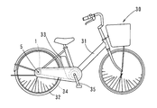
- the battery-assisted bicycle includes a rear hub motor in which a drive motor 15 is provided inside a hub 1 (hereinafter referred to as “rear hub 1”) of a rear wheel 32 that is a drive wheel.
- This is an electric assist bicycle 30 of the type.
- a power transmission element 34 such as a chain connecting the rear wheel sprocket 4 (hereinafter referred to as “rear sprocket 4”) is provided.
- the driving force can be transmitted to the rear wheels.
- the driving force generated by the output of the driving motor 15 can be transmitted to the rear wheels via the reduction mechanism 16 or the like inside the hub.
- the reverse input from the rear wheel is transmitted to the drive motor 15 through the speed reduction mechanism 16 (in the case of reverse input, the speed is increased), and the regenerative power generated by the reverse input is transmitted.
- a regenerative mechanism for returning to the secondary battery 33 supported by the frame 31 is provided.
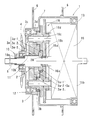
- the rear hub 1 includes a speed change mechanism 3, a speed reduction mechanism 16, and a drive motor 15 in a hub case 7 provided coaxially with the rear wheel axle 5.
- the speed change mechanism 3 is constituted by a planetary gear mechanism that can increase the speed in three stages.
- the transmission mechanism 3 includes a sun gear 3a provided on the outer periphery of the axle 5 via a transmission one-way clutch 3e.
- the sun gear 3a includes three sun gears, that is, a first sun gear 3a-1, a second sun gear 3a-2, and a third sun gear 3a-3.
- the first sun gear 3a-1, the second sun gear 3a-2, and the third sun gear 3a-3 are respectively a first one-way clutch 3e-1, a second one-way clutch 3e-2, and a third one-way clutch 3e-3. Connected through.
- a reverse input one-way clutch 2 is provided between the third sun gear 3 a-3 and the axle 5.
- a ratchet clutch is employed as each of the first one-way clutch 3e-1, the second one-way clutch 3e-2, the third one-way clutch 3e-3, and the reverse input one-way clutch 2.
- the first one-way clutch 3e-1, the second one-way clutch 3e-2, the third one-way clutch 3e-3, and the one-way clutch 2 for reverse input are respectively connected to the clutch cam surface provided on the outer periphery of the axle 5.
- the clutch pawl is engaged or disengaged.
- Each clutch pawl is biased by an elastic member in a direction in which one end thereof rises toward the clutch cam surface.
- the length of the transmission sun gear 3a in the axial direction of the axle 5 must be as short as possible because of the limited space in the rear hub 1.
- the reverse input one-way is used.
- the clutch pawl of the reverse input one-way clutch 2 and the clutch pawl of the transmission one-way clutch 3e are placed at the same position in the axial direction of the axle 5. It is possible to arrange. For this reason, the axial length of the transmission sun gear 3a is shortened.
- the reverse input one-way clutch 2 may be provided between the first sun gear 3a-1 and the axle 5 or between the second sun gear 3a-2 and the axle 5.
- the transmission mechanism 3 includes a transmission planetary gear 3b having three gears with different numbers of teeth meshing with the first sun gear 3a-1, the second sun gear 3a-2, and the third sun gear 3a-3.
- a transmission planet carrier 3c that holds the transmission planetary gear 3b, and a hub case 7 that is integral with the transmission outer ring gear 3d that meshes with the transmission planetary gear 3b.
- the outer ring gear 3d for transmission is formed integrally with the hub case 7.
- the outer ring gear 3d for transmission and the hub case 7 are formed separately and rotate together.
- a meshing configuration is also conceivable.
- bearings 11 and 12 are provided between the planetary carrier 3c for transmission and the axle 5, and between the hub case 7 and the planetary carrier 3c for transmission, respectively.
- the bearings 11 and 12 support the planetary carrier 3c for transmission and the axle 5 and the planetary carrier 3c for transmission and the hub case 7 so as to be relatively rotatable.
- a bearing portion 13 is also provided between the motor housing 15 b that holds the driving motor 15 and the hub case 7. The motor housing 15b, the hub case 7, and the axle 5 are supported by the bearing portion 13 so as to be relatively rotatable.
- the outer ring gear meshes with the second gear of the three-stage gear of the transmission planetary gear 3b.
- this embodiment is desirable because it can achieve the highest speed increase ratio.
- the transmission sun gear 3a (corresponding to the first sun gear 3a-1, the second sun gear 3a-2, and the third sun gear 3a-3) operates against the driving force by operating the speed change control mechanism 10.
- any one of the gears can be selectively fixed to the axle 5. That is, by operating the speed change control mechanism 10, the first sun gear 3a-1, the second sun gear 3a-2, and the third sun gear 3a-3 are associated with the first one-way clutch 3e-1 and the second sun gear 3e-1, respectively.
- Any one of the two one-way clutch 3e-3 and the third one-way clutch 3e-3 is fixed to the axle 5 with respect to the driving force (relative rotation is impossible). It is switched to enable relative rotation.
- the number of teeth of the first sun gear 3a-1 is a
- the number of teeth of the transmission planetary gear 3b meshed with the second sun gear 3a-2 is b
- the transmission planetary meshed with the first sun gear 3a-1 Assuming that the number of teeth of the gear 3b is c and the number of teeth of the outer ring gear 3d for transmission is d, the speed increasing ratio from the planetary carrier 3c for transmission to the outer ring gear 3d for transmission is [(a ⁇ b) / (c Xd)] + 1 It becomes.
- the second sun gear 3a-2 and the third sun gear 3a-3 are idle, and do not participate in torque transmission.
- the transmission control mechanism 10 switches the transmission one-way clutch 3e, that is, the selected one of the first one-way clutch 3e-1, the second one-way clutch 3e-2, and the third one-way clutch 3e-3 is locked.
- the switching operation to make the others free can be performed by rotating (swinging) the speed change sleeve 10 b provided on the outer periphery of the axle 5 around the axle 5.
- the rotation operation of the speed change sleeve 10 b can be performed by the operation portion 10 a provided at the end portion of the axle 5.
- the speed change sleeve 10b has a notch in a part of its circumferential direction, and the speed change sleeve 10b is rotated around the axle 5 so that the notch becomes the transmission clutch. It moves between the position of the cam surface and the position retracted from the clutch clutch cam surface, and the one-way clutch 3e for transmission is switched by this movement. Since the clutch pawl portion of the ratchet clutch has a notch portion, the clutch pawl can be engaged with the clutch cam surface. If the notch portion does not face, the clutch pawl is moved to the clutch cam surface by the speed change sleeve 10b. This is a configuration in which the engagement is prevented.
- the speed reduction mechanism 16 has a tooth provided on the outer periphery of the output shaft 15a of the drive motor 15 as a speed reducer sun gear 16a, and is integrated with a two-stage speed reducer planetary gear 16b and a motor housing 15b that mesh with the gear.
- An outer ring gear 16d (fixed) for the speed reducer and a planet carrier that holds the planetary gear 16b for the speed reducer are provided.
- the planetary carrier for the speed reducer is constituted by a planetary carrier 3c for transmission provided in the transmission mechanism 3. That is, the transmission planetary gear 3b and the reduction planetary gear 16b are supported by the transmission planetary carrier 3c by a common shaft 16c.
- the output shaft 15 a of the drive motor 15 and the axle 5 are connected coaxially by a bearing 20.
- the bearing 20 By the bearing 20, the output shaft 15a and the axle 5 can be relatively rotated around the axis.
- the drive motor 15 is arranged in parallel with the transmission mechanism 3 in the axial direction, and the output of the drive motor 15 is decelerated to the transmission planetary carrier 3 c via the reduction mechanism 16. Is transmitted.
- the transmission planetary carrier 3 c is accelerated by the transmission mechanism 3 and transmitted to the hub case 7.
- the speed increase ratio at this time varies depending on the states of the first one-way clutch 3e-1, the second one-way clutch 3e-2, and the third one-way clutch 3e-3 by the shift control mechanism 10.
- the output from the drive motor 15 is the number of teeth of the reduction gear planetary gear 16b meshing with the reduction gear sun gear 16a, the number of teeth of the reduction gear outer ring gear 16d, and the number of teeth of the reduction gear sun gear 16a.
- c is the number of teeth of the reduction gear planetary gear 16b meshing with the reduction gear outer ring gear 16d
- the reduction ratio from the reduction gear sun gear 16a to the transmission planet carrier 3c is [(a ⁇ b) / (C ⁇ d)] + 1 It becomes.
- the reverse input from the tire is transmitted from the hub case 7 to the transmission planetary gear 3b.
- the third sun gear 3a-3 is fixed to the axle 5 with respect to the reverse input by the one-way clutch 2 for reverse input provided between the third sun gear 3a-3 and the axle 5.
- the driving force (stepping force) from the rear sprocket 4 is increased and transmitted to the tire.
- the driving force from the driving motor 15 is decelerated via the speed reduction mechanism 16 and transmitted to the planetary carrier 3c for transmission, and then accelerated through the transmission mechanism 3 and transmitted to the tire.
- the reverse input torque from the tire is decelerated by the speed change mechanism 3, accelerated by the speed reduction mechanism 16, and transmitted to the drive motor 15 so that regenerative charging is possible.
- the number of stages of the planetary gear 3b for transmission is three, and the three-stage transmission mechanism 3 is used.
- the number of stages of the planetary gear 3b for transmission is two or more. You can also.
- the speed change control mechanism 10 for example, an operation in which the speed change sleeve 10b is moved in the axial direction with respect to the axle 5 is also conceivable. That is, by moving the shift sleeve 10b in the axial direction of the axle 5, the notch moves between the position of the transmission clutch cam surface and the position retracted from the transmission clutch cam surface. In this configuration, the transmission one-way clutch 3e is switched by the movement.
- the engagement of each clutch pawl of the ratchet clutch with the clutch cam surface is engaged with the state where the clutch sleeve 10b can be engaged.
- other means may be adopted as means for switching the axle 5 and the transmission sun gear 3a to be relatively rotatable and not to be relatively rotatable.
- a known bicycle transmission mechanism may be used as the transmission mechanism.
- the first one-way clutch 3e-1, the second one-way clutch 3e-2, and the third one-way clutch 3e-3 each employ a ratchet clutch as the reverse input one-way clutch 2.
- a one-way clutch having another configuration such as a roller clutch or a sprag clutch may be employed.
Abstract
Description
変速機構及び減速機構を、車軸の一端側のスプロケットと、他端側の駆動用モータとの間に設ければ、変速機用遊星キャリアと減速機用遊星キャリアとが近接するので、キャリアを共通化するための構造をさらに簡素とし得る。 In this configuration, the sprocket is provided at one end of the axle, the drive motor is provided at the other end of the axle, and the speed change mechanism and the speed reduction mechanism are provided between the sprocket and the drive motor. A configuration can be employed.
If the speed change mechanism and the speed reduction mechanism are provided between the sprocket on one end of the axle and the drive motor on the other end, the planetary carrier for the transmission and the planetary carrier for the speed reducer are close to each other. The structure for realizing the above can be further simplified.
一方、前進非駆動時には、逆入力用ワンウェイクラッチを介して、モータに逆入力が伝わることで、回生発電が可能となる。すなわち、タイヤからの逆入力に対して、太陽歯車が車軸周りに常に回転不能となるように、逆入力用ワンウェイクラッチを太陽歯車と車軸との間に設けることによって、駆動用モータにタイヤからの逆入力が伝達され、回生充電が可能となる。
このとき、タイヤからの逆入力は常に駆動用モータに伝達されるが、回生充電を行うか否かは、別に設けた周知の制御機構によって制御することができるため、例えば、ブレーキレバーの操作によって回生充電のスイッチが入るようにすることもできる。 According to the configuration including the reverse input one-way clutch, at the time of driving forward, the driving force is transmitted from the sprocket of the driving wheel to the hub via the speed change mechanism, and the bicycle moves forward. At this time, the reverse input one-way clutch always idles with respect to the driving force.
On the other hand, at the time of forward non-drive, regenerative power generation becomes possible by transmitting the reverse input to the motor via the reverse input one-way clutch. That is, by providing a reverse input one-way clutch between the sun gear and the axle so that the sun gear cannot always rotate around the axle against reverse input from the tire, the drive motor is Reverse input is transmitted, and regenerative charging is possible.
At this time, the reverse input from the tire is always transmitted to the drive motor, but whether or not to perform regenerative charging can be controlled by a well-known control mechanism provided separately, for example, by operating the brake lever The regenerative charging can be switched on.
ハブ内の車軸の軸方向へのスペースには制約があることから、変速制御機構は、このように、変速機用スリーブを車軸周りに回転運動(揺動運動)させることによって、各変速機用ワンウェイクラッチの切替を行う機構を用いることが好ましい。 When a ratchet clutch is employed as the one-way clutch for the transmission, the transmission control mechanism includes, for example, a transmission sleeve fitted around the axle, and the transmission sleeve is rotated about the axle. Therefore, it is possible to adopt a configuration in which the one-way clutch for transmission is switched between the rotatable state and the non-rotatable state.
Since the space in the axial direction of the axle in the hub is limited, the speed change control mechanism is used for each transmission by rotating (swinging) the transmission sleeve around the axle in this way. It is preferable to use a mechanism for switching the one-way clutch.
その第一太陽歯車3a-1、第二太陽歯車3a-2、第三太陽歯車3a-3が、それぞれ第一ワンウェイクラッチ3e-1、第二ワンウェイクラッチ3e-2、第三ワンウェイクラッチ3e-3を介して接続されている。 The
The
この第一ワンウェイクラッチ3e-1、第二ワンウェイクラッチ3e-2、第三ワンウェイクラッチ3e-3、及び、前記逆入力用ワンウェイクラッチ2は、それぞれ車軸5の外周に設けられたクラッチカム面に対し、クラッチ爪が係合又は係合解除する構造となっている。なお、各クラッチ爪は、弾性部材によって、その一端がクラッチカム面に向かって、起き上がる方向に付勢されている。 In this embodiment, a ratchet clutch is employed as each of the first one-way clutch 3e-1, the second one-way clutch 3e-2, the third one-way clutch 3e-3, and the reverse input one-
The first one-way clutch 3e-1, the second one-way clutch 3e-2, the third one-way clutch 3e-3, and the one-
また、駆動用のモータ15を保持するモータハウジング15bとハブケース7との間にも、軸受部13が設けられている。この軸受部13によって、モータハウジング15bとハブケース7と車軸5とは相対回転可能に支持されている。 Further,
A bearing
[(a×b)/(c×d)]+1
となる。このとき、第二太陽歯車3a-2、第三太陽歯車3a-3は空転状態であり、トルク伝達に関与しない。 At this time, the number of teeth of the
It becomes. At this time, the
(a+d)/d
となる。 When the
It becomes.
[(a×b)/(c×d)]+1
となる。 When the
It becomes.
[(a×b)/(c×d)]+1
となる。 The output from the
It becomes.
一方、タイヤからの逆入力トルクは、変速機構3により減速され、減速機構16により増速されて駆動用モータ15に伝わり、回生充電が可能な状態となる。 With these configurations, the driving force (stepping force) from the
On the other hand, the reverse input torque from the tire is decelerated by the
2 逆入力用ワンウェイクラッチ
3 変速機構
3a 変速機用太陽歯車
3a-1 第一太陽歯車
3a-2 第二太陽歯車
3a-3 第三太陽歯車
3b 変速機用遊星歯車
3c 変速機用遊星キャリア
3d 変速機用外輪歯車
3e 変速機用ワンウェイクラッチ
3e-1 第一ワンウェイクラッチ
3e-2 第二ワンウェイクラッチ
3e-3 第三ワンウェイクラッチ
4 リアスプロケット(スプロケット)
5 車軸
6 ハブフランジ
7 ハブケース
10 変速制御機構
10a 変速操作部
10b 変速用スリーブ
11,12,13 軸受部
15 駆動用モータ
15a 出力軸
15b モータハウジング
16 減速機構
16a 減速機用太陽歯車
16b 減速機用遊星歯車
16c 軸
16d 減速機用外輪歯車
20 軸受
30 電動補助自転車
31 フレーム
32 後輪
33 二次電池
34 動力伝達要素
35 ペダル 1 Rear hub (hub)
2 Reverse input one-
5
Claims (10)
- 駆動輪のハブ(1)内部に、変速機構(3)、減速機構(16)及び駆動用モータ(15)を車軸(5)の軸方向に並列して配置し、前記変速機構(3)は、ペダルからの踏力による駆動力をスプロケット(4)を通じて前記駆動輪に伝達する機能を有し、前記減速機構(16)は、前記駆動用モータ(15)からの駆動力を前記駆動輪に伝達する機能を有し、前記変速機構(3)は、遊星歯車機構によって構成されて少なくとも1つの変速機用太陽歯車(3a)と、その変速機用太陽歯車(3a)に噛み合う変速機用遊星歯車(3b)、及びその変速機用遊星歯車(3b)を保持する変速機用遊星キャリア(3c)とを備え、前記スプロケット(4)からの駆動力に対して前記変速機用太陽歯車(3a)が前記車軸(5)周りに回転可能又は回転不能とに切り替えて変速を行う変速制御機構(10)を備えており、前記減速機構(16)は、遊星歯車機構によって構成されて少なくとも1つの減速機用太陽歯車(16a)と、その減速機用太陽歯車(16a)に噛み合う減速機用遊星歯車(16b)とを備え、前記減速機用遊星歯車(16b)を、前記変速機用遊星キャリア(3c)又はその変速機用遊星キャリア(3c)と一体に回転する部材で保持したことを特徴とする電動補助自転車。 A transmission mechanism (3), a speed reduction mechanism (16), and a drive motor (15) are arranged in parallel in the axial direction of the axle (5) inside the hub (1) of the drive wheel, and the transmission mechanism (3) And a function of transmitting a driving force by a pedaling force from a pedal to the driving wheel through a sprocket (4), and the speed reduction mechanism (16) transmits a driving force from the driving motor (15) to the driving wheel. The transmission mechanism (3) is constituted by a planetary gear mechanism and is configured by at least one transmission sun gear (3a) and the transmission planetary gear meshed with the transmission sun gear (3a). (3b) and a planetary carrier (3c) for transmission that holds the planetary gear (3b) for transmission, and the sun gear for transmission (3a) against the driving force from the sprocket (4) Is rotatable around the axle (5) Is provided with a speed change control mechanism (10) for switching to non-rotatable, and the speed reduction mechanism (16) is constituted by a planetary gear mechanism and at least one speed reducer sun gear (16a), A reduction gear planetary gear (16b) meshing with the reduction gear sun gear (16a), and the reduction gear planetary gear (16b) is connected to the transmission planet carrier (3c) or a transmission planet carrier ( A battery-assisted bicycle that is held by a member that rotates integrally with 3c).
- 前記スプロケット(4)を前記車軸(5)の一端側に、前記駆動用モータ(15)を前記車軸(5)の他端側に設け、前記変速機構(3)及び前記減速機構(16)は、前記スプロケット(4)と前記駆動用モータ(5)との間に設けられることを特徴とする請求項1に記載の電動補助自転車。 The sprocket (4) is provided at one end of the axle (5), the drive motor (15) is provided at the other end of the axle (5), and the speed change mechanism (3) and the speed reduction mechanism (16) The battery-assisted bicycle according to claim 1, wherein the battery-assisted bicycle is provided between the sprocket (4) and the drive motor (5).
- 前記変速機用太陽歯車(3a)と前記車軸(5)との間に逆入力用ワンウェイクラッチ(2)を設け、その逆入力用ワンウェイクラッチ(2)をロックすることにより、前記駆動輪から前記駆動用モータ(15)への逆入力を伝達可能とし、その逆入力により生じた回生電力を二次電池に還元する回生機構を備えたことを特徴とする請求項1又は2に記載の電動補助自転車。 By providing a reverse input one-way clutch (2) between the transmission sun gear (3a) and the axle (5) and locking the reverse input one-way clutch (2), The electric auxiliary according to claim 1 or 2, further comprising a regenerative mechanism that enables transmission of reverse input to the drive motor (15) and reduces regenerative power generated by the reverse input to the secondary battery. bicycle.
- 前記逆入力用ワンウェイクラッチ(2)がラチェットクラッチ機構からなることを特徴とする請求項3に記載の電動補助自転車。 The battery-assisted bicycle according to claim 3, wherein the one-way clutch for reverse input (2) comprises a ratchet clutch mechanism.
- 前記変速制御機構(10)は、全ての前記変速機用太陽歯車(3a)と前記車軸(5)の間にそれぞれ変速機用ワンウェイクラッチ(3e)を備え、その各変速機用ワンウェイクラッチ(3e)によって、前記変速機用太陽歯車(3a)のいずれか一つを前記車軸(5)周りに回転不能に、他を回転可能に切り替えることで変速を行うことを特徴とする請求項1乃至4のいずれか一つに記載の電動補助自転車。 The transmission control mechanism (10) includes a transmission one-way clutch (3e) between all the transmission sun gears (3a) and the axle (5), and each transmission one-way clutch (3e). ) To change the speed by switching one of the transmission sun gears (3a) to be non-rotatable around the axle (5) and the other to be rotatable. The battery-assisted bicycle according to any one of the above.
- 前記変速機用ワンウェイクラッチ(3e)は、ラチェットクラッチ機構からなることを特徴とする請求項5に記載の電動補助自転車。 The battery-assisted bicycle according to claim 5, wherein the one-way clutch for transmission (3e) comprises a ratchet clutch mechanism.
- 前記変速制御機構(10)は、前記車軸(5)周りに嵌められた変速機用スリーブ(10b)を備え、その変速機用スリーブ(10b)を前記車軸(5)回りに回転させることによって、前記変速機用ワンウェイクラッチ(3e)の前記回転可能又は回転不能との切り替えを行うことを特徴とする請求項6に記載の電動補助自転車。 The transmission control mechanism (10) includes a transmission sleeve (10b) fitted around the axle (5), and by rotating the transmission sleeve (10b) around the axle (5), The battery-assisted bicycle according to claim 6, wherein the one-way clutch for transmission (3e) is switched between the rotatable state and the non-rotatable state.
- 前記変速機用ワンウェイクラッチ(3e)は、前記変速機用太陽歯車(3a)又は車軸(5)の一方に変速機用クラッチカム面を有し、他方にはその変速機用クラッチカム面に噛み合うことができる揺動自在の変速用クラッチ爪を有し、前記変速用スリーブ(10b)はその周方向の一部に切欠部を有し、前記変速用スリーブ(10b)を前記車軸(5)回りに回転させることにより、前記切欠部が前記変速機用クラッチカム面の位置と前記変速機用クラッチカム面から退避した位置との間で移動し、その移動によって、前記変速機用ワンウェイクラッチ(3e)の切り替えを行うことを特徴とする請求項7に記載の電動補助自転車。 The transmission one-way clutch (3e) has a transmission clutch cam surface on one of the transmission sun gear (3a) or the axle (5), and the other meshes with the transmission clutch cam surface. The shift sleeve (10b) has a notch in a part of its circumferential direction, and the shift sleeve (10b) is rotated around the axle (5). The notch is moved between the position of the transmission clutch cam surface and the position retracted from the transmission clutch cam surface, and the movement of the one-way clutch (3e) The battery-assisted bicycle according to claim 7, wherein switching is performed.
- 前記減速機用遊星歯車(16b)を二段歯車としたことを特徴とする請求項1乃至8のいずれか一つに記載の電動補助自転車。 The battery-assisted bicycle according to any one of claims 1 to 8, wherein the planetary gear (16b) for the speed reducer is a two-stage gear.
- 前記駆動用モータ(15)の出力軸(15a)と前記車軸(5)とを同軸状に接続し、前記出力軸(15a)と前記車軸(5)とを軸受(20)によって相対回転可能に支持したことを特徴とする請求項1乃至9のいずれか一つに記載の電動補助自転車。 The output shaft (15a) of the drive motor (15) and the axle (5) are coaxially connected, and the output shaft (15a) and the axle (5) can be relatively rotated by a bearing (20). The battery-assisted bicycle according to any one of claims 1 to 9, wherein the bicycle is supported.
Priority Applications (3)
| Application Number | Priority Date | Filing Date | Title |
|---|---|---|---|
| EP11744562.7A EP2537740B1 (en) | 2010-02-18 | 2011-02-09 | Electric bicycle |
| US13/577,684 US8636095B2 (en) | 2010-02-18 | 2011-02-09 | Electric power-assisted bicycle |
| CN201180009821.6A CN102762441B (en) | 2010-02-18 | 2011-02-09 | Electrically assisted bicycle |
Applications Claiming Priority (2)
| Application Number | Priority Date | Filing Date | Title |
|---|---|---|---|
| JP2010-033430 | 2010-02-18 | ||
| JP2010033430A JP5561586B2 (en) | 2010-02-18 | 2010-02-18 | Electric assist bicycle |
Publications (1)
| Publication Number | Publication Date |
|---|---|
| WO2011102275A1 true WO2011102275A1 (en) | 2011-08-25 |
Family
ID=44482862
Family Applications (1)
| Application Number | Title | Priority Date | Filing Date |
|---|---|---|---|
| PCT/JP2011/052743 WO2011102275A1 (en) | 2010-02-18 | 2011-02-09 | Electric bicycle |
Country Status (5)
| Country | Link |
|---|---|
| US (1) | US8636095B2 (en) |
| EP (1) | EP2537740B1 (en) |
| JP (1) | JP5561586B2 (en) |
| CN (1) | CN102762441B (en) |
| WO (1) | WO2011102275A1 (en) |
Cited By (4)
| Publication number | Priority date | Publication date | Assignee | Title |
|---|---|---|---|---|
| US20130095971A1 (en) * | 2011-10-13 | 2013-04-18 | Shimano Inc. | Bicycle drive unit |
| DE102012201373A1 (en) * | 2012-01-31 | 2013-08-01 | Zf Friedrichshafen Ag | Hub gearshift for hybrid drive train of bike, has two power paths, which are provided between gearbox input and downstream gear set, where shaft of downstream gear set is connectable with former power path by switching element |
| CN103359254A (en) * | 2012-03-30 | 2013-10-23 | 本田技研工业株式会社 | Electric vehicle |
| CN116902126A (en) * | 2023-09-12 | 2023-10-20 | 金华澳特玛科技有限公司 | Double-magnetic power motor and electric bicycle thereof |
Families Citing this family (31)
| Publication number | Priority date | Publication date | Assignee | Title |
|---|---|---|---|---|
| JP5149938B2 (en) * | 2010-06-11 | 2013-02-20 | 株式会社シマノ | Bicycle hub with built-in motor |
| JP5205436B2 (en) * | 2010-10-29 | 2013-06-05 | 株式会社シマノ | Bicycle motor control system |
| ITMO20110061A1 (en) * | 2011-03-16 | 2012-09-17 | C R D Ct Ricerche Ducati Trent O S R L | WHEEL FOR ASSISTED RIDING BICYCLES |
| TWI481162B (en) * | 2012-10-16 | 2015-04-11 | Yung Sung Huang | Double motor drive device and its internal variable speed double motor and clutch deceleration drive device |
| US9758213B2 (en) * | 2013-07-16 | 2017-09-12 | Panasonic Intellectual Property Management Co., Ltd. | Electric assist bicycle |
| KR20150061963A (en) * | 2013-11-28 | 2015-06-05 | 주식회사 만도 | Drive unit for electric bicycle |
| NL2012611B1 (en) * | 2014-02-28 | 2016-05-09 | Dti Advanced Tech B V | Bicycle with only one front sprocket. |
| KR101574048B1 (en) * | 2015-01-14 | 2015-12-03 | 국창권 | Stepping type kick board and kick board style mini bicycle |
| US9771124B2 (en) | 2015-02-25 | 2017-09-26 | Ford Global Technologies, Llc | Wheel rim-mounted regeneration coil-magnet system |
| CN104709429B (en) * | 2015-03-20 | 2017-05-24 | 北京轻客智能科技有限责任公司 | Power control method of power-assisted bicycle |
| JP6453127B2 (en) | 2015-03-25 | 2019-01-16 | 株式会社シマノ | Bicycle drive unit |
| WO2016201705A1 (en) * | 2015-06-19 | 2016-12-22 | Robert Bosch Gmbh | Electric vehicle and driving system for electric vehicle |
| US9925999B2 (en) | 2015-09-29 | 2018-03-27 | Radio Flyer Inc. | Power assist wagon |
| JP6788968B2 (en) | 2015-12-28 | 2020-11-25 | 株式会社シマノ | Gears and transmissions for bicycles equipped with them |
| JP2017132439A (en) * | 2016-01-29 | 2017-08-03 | 株式会社シマノ | Bicycle drive device |
| JP6374903B2 (en) * | 2016-04-07 | 2018-08-15 | 株式会社シマノ | Bicycle transmission |
| KR101782895B1 (en) * | 2016-05-12 | 2017-09-28 | 복 성 김 | Bicycle transmission hub |
| KR101685599B1 (en) * | 2016-07-08 | 2016-12-13 | 주식회사 에이치엔이 | The Electric bicycle battery-powered drive unit |
| US10479441B2 (en) * | 2016-08-23 | 2019-11-19 | Shimano Inc. | Bicycle hub assembly and bicycle control system |
| US10583852B2 (en) | 2016-11-02 | 2020-03-10 | Radio Flyer Inc. | Foldable wagon |
| KR102004600B1 (en) * | 2017-01-11 | 2019-10-01 | 신성호 | Bicycle with Electric motor |
| IT201700062839A1 (en) * | 2017-06-08 | 2018-12-08 | Sergio Capraro | A VEHICLE |
| CN107685828B (en) * | 2017-09-19 | 2023-03-24 | 八方电气(苏州)股份有限公司 | Stepless speed change transmission device for electric bicycle |
| USD866676S1 (en) | 2017-11-02 | 2019-11-12 | Radio Flyer Inc. | Foldable wagon |
| CN110203058A (en) * | 2019-05-31 | 2019-09-06 | 贵州航天林泉电机有限公司 | A kind of wheel hub electric drive assembly of parallel shaft (speed) reducer |
| GB2580446B (en) * | 2019-06-05 | 2020-12-16 | Ebike Systems Ltd | Electrically-assisted pedal cycles |
| TWI755737B (en) * | 2020-05-22 | 2022-02-21 | 新加坡商普拉希斯國際有限公司 | In-wheel motor with high torque to volume ratio |
| KR102405909B1 (en) * | 2020-07-27 | 2022-06-08 | 현대모비스 주식회사 | Power transmission device and automobile including the same |
| NL2026760B1 (en) * | 2020-10-23 | 2022-06-17 | Advatech B V | Hybrid drive system for a bicycle |
| TWI756895B (en) * | 2020-11-02 | 2022-03-01 | 姚立和 | Power alternative structure |
| DE102021000585B4 (en) * | 2021-02-05 | 2024-04-18 | EGS Entwicklungsgesellschaft für Getriebesysteme mbH | Modular drive system |
Citations (1)
| Publication number | Priority date | Publication date | Assignee | Title |
|---|---|---|---|---|
| JPH11255177A (en) * | 1998-03-16 | 1999-09-21 | Yamaha Motor Co Ltd | Motor driven bicycle |
Family Cites Families (15)
| Publication number | Priority date | Publication date | Assignee | Title |
|---|---|---|---|---|
| JP3306261B2 (en) | 1995-08-30 | 2002-07-24 | 三洋電機株式会社 | Electric car |
| JP3194088B2 (en) * | 1998-03-19 | 2001-07-30 | 本田技研工業株式会社 | Auxiliary driving force generator for assist vehicle |
| US6100615A (en) * | 1998-05-11 | 2000-08-08 | Birkestrand; Orville J. | Modular motorized electric wheel hub assembly for bicycles and the like |
| JP2000043780A (en) | 1998-05-29 | 2000-02-15 | Sanyo Electric Co Ltd | Motor car |
| JP3939862B2 (en) * | 1998-08-18 | 2007-07-04 | ヤマハ発動機株式会社 | Motor drive unit for electric bicycle |
| JP2000211574A (en) * | 1999-01-25 | 2000-08-02 | Yamaha Motor Co Ltd | Electric power assited bicycle |
| JP4437623B2 (en) | 2001-03-30 | 2010-03-24 | ヤマハ発動機株式会社 | Power assisted bicycle power unit |
| JP3849452B2 (en) * | 2001-04-26 | 2006-11-22 | 株式会社明電舎 | Electric assist bicycle driving device. |
| JP2003095180A (en) * | 2001-09-21 | 2003-04-03 | Sanyo Electric Co Ltd | Electrically assisted bicycle |
| JP2003160089A (en) | 2001-11-27 | 2003-06-03 | Sanyo Electric Co Ltd | Drive device for vehicle with auxiliary power |
| US6974399B2 (en) * | 2004-02-11 | 2005-12-13 | Chiu-Hsiang Lo | Hub motor mechanism |
| FR2873090A1 (en) * | 2004-07-16 | 2006-01-20 | Inivi T Sarl | Wheel hub for bicycle, has pedaling assistance device with motor connected to body flange and reducer having splined crown gear which has flange in which recess is arranged to form cylindrical housing for receiving speed shifting unit |
| DE102005003056A1 (en) * | 2005-01-22 | 2006-07-27 | Sram Deutschland Gmbh | Changing movement transmission device for e.g. bicycle gear, has gear cable or cable that is guided between pinion and frame drop out and introduced into hub gear through axially running opening between support cone and axis |
| JP2006306360A (en) * | 2005-03-31 | 2006-11-09 | Fujiwara Wheel:Kk | Transmission apparatus for bicycle |
| EP2028096A1 (en) * | 2007-08-23 | 2009-02-25 | Urs Elsasser | Multigear epicyclical gear hub |
-
2010
- 2010-02-18 JP JP2010033430A patent/JP5561586B2/en not_active Expired - Fee Related
-
2011
- 2011-02-09 WO PCT/JP2011/052743 patent/WO2011102275A1/en active Application Filing
- 2011-02-09 US US13/577,684 patent/US8636095B2/en not_active Expired - Fee Related
- 2011-02-09 CN CN201180009821.6A patent/CN102762441B/en not_active Expired - Fee Related
- 2011-02-09 EP EP11744562.7A patent/EP2537740B1/en not_active Not-in-force
Patent Citations (1)
| Publication number | Priority date | Publication date | Assignee | Title |
|---|---|---|---|---|
| JPH11255177A (en) * | 1998-03-16 | 1999-09-21 | Yamaha Motor Co Ltd | Motor driven bicycle |
Non-Patent Citations (1)
| Title |
|---|
| See also references of EP2537740A4 * |
Cited By (7)
| Publication number | Priority date | Publication date | Assignee | Title |
|---|---|---|---|---|
| US20130095971A1 (en) * | 2011-10-13 | 2013-04-18 | Shimano Inc. | Bicycle drive unit |
| US9017201B2 (en) * | 2011-10-13 | 2015-04-28 | Shimano Inc. | Bicycle drive unit |
| DE102012201373A1 (en) * | 2012-01-31 | 2013-08-01 | Zf Friedrichshafen Ag | Hub gearshift for hybrid drive train of bike, has two power paths, which are provided between gearbox input and downstream gear set, where shaft of downstream gear set is connectable with former power path by switching element |
| DE102012201373B4 (en) | 2012-01-31 | 2022-04-21 | Zf Friedrichshafen Ag | Hybrid powertrain for a motor vehicle |
| CN103359254A (en) * | 2012-03-30 | 2013-10-23 | 本田技研工业株式会社 | Electric vehicle |
| CN116902126A (en) * | 2023-09-12 | 2023-10-20 | 金华澳特玛科技有限公司 | Double-magnetic power motor and electric bicycle thereof |
| CN116902126B (en) * | 2023-09-12 | 2023-12-19 | 金华澳特玛科技有限公司 | Double-magnetic power motor and electric bicycle thereof |
Also Published As
| Publication number | Publication date |
|---|---|
| JP5561586B2 (en) | 2014-07-30 |
| CN102762441A (en) | 2012-10-31 |
| JP2011168160A (en) | 2011-09-01 |
| US20120305325A1 (en) | 2012-12-06 |
| EP2537740A1 (en) | 2012-12-26 |
| EP2537740A4 (en) | 2013-07-31 |
| US8636095B2 (en) | 2014-01-28 |
| CN102762441B (en) | 2015-11-25 |
| EP2537740B1 (en) | 2016-12-21 |
Similar Documents
| Publication | Publication Date | Title |
|---|---|---|
| JP5561586B2 (en) | Electric assist bicycle | |
| US8684122B2 (en) | Power assisted bicycle with regenerative function | |
| WO2011162200A1 (en) | Electrically assisted bicycle | |
| JP2016078618A (en) | Bicycle assist unit | |
| JP2012025328A (en) | Power-assisted bicycle | |
| JP2012116215A (en) | Power-assisted bicycle, and electric motorcycle | |
| JP2011126416A (en) | Rear hub built-in transmission for power-assisted bicycle | |
| WO2012077538A1 (en) | Electrically assisted bicycle and electric two-wheeled vehicle | |
| JP2011126415A (en) | Rear hub built-in transmission for power-assisted bicycle | |
| JP2011189877A (en) | Power-assisted bicycle with regeneration mechanism | |
| JP2013129336A (en) | Hub unit for electric power-assisted human-powered vehicle and electric power-assisted human-powered vehicle | |
| JP2012086654A (en) | Power-assisted bicycle | |
| JP5567409B2 (en) | Electric assist bicycle | |
| WO2012026325A1 (en) | Electrically assisted bicycle | |
| JP2012086628A (en) | Power-assisted bicycle | |
| JP2010274900A (en) | Electric auxiliary bicycle including regeneration mechanism | |
| JP5545520B2 (en) | Electric assist bicycle with regenerative mechanism | |
| JP5771046B2 (en) | Electric assist bicycle with regenerative mechanism | |
| WO2012132927A1 (en) | Hub unit for bicycle, electrically assisted bicycle using hub unit for bicycle, and electric two-wheeled vehicle using hub unit for bicycle | |
| JP2011025808A (en) | Power-assisted bicycle including regenerative mechanism | |
| TWM494744U (en) | Assembly for bicycle | |
| JP2012066723A (en) | Power-assisted bicycle with regeneration mechanism | |
| JP2012025332A (en) | Power-assisted bicycle | |
| JP2015105012A (en) | Drive device of electric vehicle | |
| JP2012040941A (en) | Power-assisted bicycle |
Legal Events
| Date | Code | Title | Description |
|---|---|---|---|
| WWE | Wipo information: entry into national phase |
Ref document number: 201180009821.6 Country of ref document: CN |
|
| 121 | Ep: the epo has been informed by wipo that ep was designated in this application |
Ref document number: 11744562 Country of ref document: EP Kind code of ref document: A1 |
|
| WWE | Wipo information: entry into national phase |
Ref document number: 13577684 Country of ref document: US |
|
| NENP | Non-entry into the national phase |
Ref country code: DE |
|
| REEP | Request for entry into the european phase |
Ref document number: 2011744562 Country of ref document: EP |
|
| WWE | Wipo information: entry into national phase |
Ref document number: 2011744562 Country of ref document: EP |