WO2012132879A1 - 電池の安全弁製造方法、電池の安全弁製造装置、電池の安全弁、及び電池ケースの蓋体製造方法 - Google Patents
電池の安全弁製造方法、電池の安全弁製造装置、電池の安全弁、及び電池ケースの蓋体製造方法 Download PDFInfo
- Publication number
- WO2012132879A1 WO2012132879A1 PCT/JP2012/056419 JP2012056419W WO2012132879A1 WO 2012132879 A1 WO2012132879 A1 WO 2012132879A1 JP 2012056419 W JP2012056419 W JP 2012056419W WO 2012132879 A1 WO2012132879 A1 WO 2012132879A1
- Authority
- WO
- WIPO (PCT)
- Prior art keywords
- annular
- safety valve
- metal plate
- battery
- thin portion
- Prior art date
Links
Images


Classifications
-
- H—ELECTRICITY
- H01—ELECTRIC ELEMENTS
- H01M—PROCESSES OR MEANS, e.g. BATTERIES, FOR THE DIRECT CONVERSION OF CHEMICAL ENERGY INTO ELECTRICAL ENERGY
- H01M50/00—Constructional details or processes of manufacture of the non-active parts of electrochemical cells other than fuel cells, e.g. hybrid cells
- H01M50/30—Arrangements for facilitating escape of gases
-
- H—ELECTRICITY
- H01—ELECTRIC ELEMENTS
- H01M—PROCESSES OR MEANS, e.g. BATTERIES, FOR THE DIRECT CONVERSION OF CHEMICAL ENERGY INTO ELECTRICAL ENERGY
- H01M50/00—Constructional details or processes of manufacture of the non-active parts of electrochemical cells other than fuel cells, e.g. hybrid cells
- H01M50/10—Primary casings, jackets or wrappings of a single cell or a single battery
- H01M50/147—Lids or covers
-
- B—PERFORMING OPERATIONS; TRANSPORTING
- B21—MECHANICAL METAL-WORKING WITHOUT ESSENTIALLY REMOVING MATERIAL; PUNCHING METAL
- B21D—WORKING OR PROCESSING OF SHEET METAL OR METAL TUBES, RODS OR PROFILES WITHOUT ESSENTIALLY REMOVING MATERIAL; PUNCHING METAL
- B21D51/00—Making hollow objects
- B21D51/16—Making hollow objects characterised by the use of the objects
- B21D51/38—Making inlet or outlet arrangements of cans, tins, baths, bottles, or other vessels; Making can ends; Making closures
- B21D51/383—Making inlet or outlet arrangements of cans, tins, baths, bottles, or other vessels; Making can ends; Making closures scoring lines, tear strips or pulling tabs
-
- H—ELECTRICITY
- H01—ELECTRIC ELEMENTS
- H01M—PROCESSES OR MEANS, e.g. BATTERIES, FOR THE DIRECT CONVERSION OF CHEMICAL ENERGY INTO ELECTRICAL ENERGY
- H01M50/00—Constructional details or processes of manufacture of the non-active parts of electrochemical cells other than fuel cells, e.g. hybrid cells
- H01M50/30—Arrangements for facilitating escape of gases
- H01M50/342—Non-re-sealable arrangements
- H01M50/3425—Non-re-sealable arrangements in the form of rupturable membranes or weakened parts, e.g. pierced with the aid of a sharp member
-
- Y—GENERAL TAGGING OF NEW TECHNOLOGICAL DEVELOPMENTS; GENERAL TAGGING OF CROSS-SECTIONAL TECHNOLOGIES SPANNING OVER SEVERAL SECTIONS OF THE IPC; TECHNICAL SUBJECTS COVERED BY FORMER USPC CROSS-REFERENCE ART COLLECTIONS [XRACs] AND DIGESTS
- Y02—TECHNOLOGIES OR APPLICATIONS FOR MITIGATION OR ADAPTATION AGAINST CLIMATE CHANGE
- Y02E—REDUCTION OF GREENHOUSE GAS [GHG] EMISSIONS, RELATED TO ENERGY GENERATION, TRANSMISSION OR DISTRIBUTION
- Y02E60/00—Enabling technologies; Technologies with a potential or indirect contribution to GHG emissions mitigation
- Y02E60/10—Energy storage using batteries
-
- Y—GENERAL TAGGING OF NEW TECHNOLOGICAL DEVELOPMENTS; GENERAL TAGGING OF CROSS-SECTIONAL TECHNOLOGIES SPANNING OVER SEVERAL SECTIONS OF THE IPC; TECHNICAL SUBJECTS COVERED BY FORMER USPC CROSS-REFERENCE ART COLLECTIONS [XRACs] AND DIGESTS
- Y02—TECHNOLOGIES OR APPLICATIONS FOR MITIGATION OR ADAPTATION AGAINST CLIMATE CHANGE
- Y02P—CLIMATE CHANGE MITIGATION TECHNOLOGIES IN THE PRODUCTION OR PROCESSING OF GOODS
- Y02P70/00—Climate change mitigation technologies in the production process for final industrial or consumer products
- Y02P70/50—Manufacturing or production processes characterised by the final manufactured product
Definitions
- the present invention relates to a battery safety valve manufacturing method, a battery safety valve manufacturing apparatus, a battery safety valve, and a battery case lid manufacturing method, and in particular, to a punch and a die using a stainless steel metal plate so as to face each other.
- a punch and a die using a stainless steel metal plate so as to face each other.
- the annular thin portion constituting the edge of the safety valve is formed on the metal plate, so that the annular thin portion can be formed with high precision and the annular thin portion is
- the present invention relates to a novel improvement for making it possible to disperse the processing load at the time of forming the punch and the die and to prolong the life of the mold.
- a battery containing an electrolyte solution in a sealed battery case is cleaved when the pressure in the battery case exceeds a predetermined value in order to prevent the pressure in the battery case from rising and exploding.
- a safety valve for releasing the pressure in the battery case to the outside is provided.
- the method disclosed in Patent Document 1 below can be cited.
- a metal plate that serves as a lid for a battery case is disposed between a stamping punch having an annular protrusion and a flat die, and the metal plate is supported by the flat die.
- the annular thin portion constituting the edge of the safety valve is formed on the metal plate by pressing the annular protrusion of the marking punch against the metal plate.
- the annular thin portion is a portion that should be torn first when the pressure in the battery case exceeds a predetermined value, and the thickness thereof is reduced to, for example, about 0.010 mm. That is, the punch and die for forming such an annular thin portion are also very delicate.
- the annular thin wall portion is formed on the metal plate by pressing the annular protrusion of the engraving punch against the metal plate while supporting the metal plate with a flat die. Therefore, the annular thin portion is formed by deforming the metal substantially only by the annular protrusion of the marking punch.
- a soft metal such as aluminum has been used for the metal plate forming the safety valve, but in recent years, it has been proposed to use stainless steel in order to improve the corrosion resistance and strength of the battery case.
- the metal plate is aluminum, it is soft, so the thin annular part can be processed with high precision and the load on the mold is small, so it can be processed without problems.
- the material is hard and hard. Therefore, if the annular thin portion of the safety valve is to be processed by the conventional method, there is a problem that cracks are likely to occur during the processing, and the thin portion cannot be processed with high accuracy by work hardening.
- the conventional method has a problem that the life of the mold is shortened because the load at the time of forming the annular thin portion is concentrated on the annular protrusion of the stamping punch.
- the present invention has been made in order to solve the above-described problems, and its purpose is to accurately form the annular thin portion and distribute the processing load when forming the annular thin portion to the punch and die. It is possible to provide a battery safety valve manufacturing method, a battery safety valve manufacturing apparatus, a battery safety valve, and a battery case lid manufacturing method capable of extending the life of a mold.
- a stainless steel metal plate constituting a battery case of a battery is disposed between a punch and a die, and an annular protrusion provided on the punch and the die so as to face each other.
- An annular thin part constituting the edge of the safety valve is formed on the metal plate by pressing the parts simultaneously on both sides of the metal plate.
- a battery safety valve manufacturing apparatus includes a plurality of sets of punches and dies, and a plurality of sets of annular protrusions provided on the punches and dies so as to face each other and having different tip widths for each set of punches and dies. And a restraining means arranged on the outer peripheral side of the annular protrusion of each punch and die, while restraining the stainless steel metal plate constituting the battery case of the battery on the outer peripheral side of the annular protrusion by the restraining means, By simultaneously pressing the annular protrusions on both surfaces of the metal plate in the descending order of the tip width, the thin annular portion constituting the edge of the safety valve is formed on the metal plate.
- the battery safety valve according to the present invention includes a pair of annular protrusions that are formed on both surfaces of a metal plate by pressing the opposite annular protrusions simultaneously against both surfaces of a stainless steel metal plate constituting the battery case of the battery.
- An annular thin portion comprising a concave portion and a bent portion provided on the inner peripheral side of the annular thin portion and bent and deformed along the plate thickness direction by the action of pressing.
- a safety valve having an edge formed by an annular thin portion, and a side wall portion standing in an annular shape from the outer edge of the outer peripheral plate surface located on the outer peripheral side of the annular thin portion
- the annular protrusions arranged to face each other are formed.
- An annular thin part is formed by simultaneously pressing the front and back surfaces of the metal plate.
- the annular protrusions provided on the punch and the die so as to face each other are made of stainless steel.
- an annular thin portion constituting the edge of the safety valve is formed on the metal plate, so that the processing amount of the metal plate by one annular projection can be reduced, and one annular projection can be formed on one annular projection.
- the applied processing load can be reduced.
- the annular thin portion can be accurately formed, and the processing load when forming the annular thin portion can be distributed to the punch and die, thereby extending the life of the mold. Can do.
- FIG. 2 is a sectional view taken along line II-II in FIG. It is an enlarged view of the area
- FIG. 6 is a block diagram which shows the safety valve manufacturing apparatus for manufacturing the safety valve of FIG.
- FIG. 6 is a sectional view taken along line VI-VI in FIG. 5. It is an enlarged view of the area
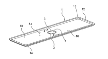
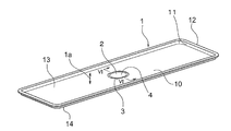
- FIG. 1 is a perspective view showing a safety valve 2 of a secondary battery according to Embodiment 1 of the present invention.
- a lid 1 is made of a stainless steel metal plate and constitutes a battery case of a secondary battery.
- the lid 1 is provided with a secondary battery safety valve 2 that is opened when the internal pressure of the battery case exceeds a predetermined value and opens the internal pressure to the outside.
- the safety valve 2 is provided with an annular thin portion 3 and a bent portion 4.
- the annular thin portion 3 is an oval groove that constitutes the edge of the safety valve 2, and is a portion that is thinner than the other plate surface in the lid 1.
- the annular thin portion 3 is torn first when the internal pressure of the battery case exceeds a predetermined value, and cleaves the entire safety valve 2.
- the outer shape of the annular thin portion 3 only needs to have a closed outer edge, and may be, for example, a perfect circle or a polygon.
- the bent portion 4 is a plate surface located on the inner peripheral side of the annular thin portion 3, and is a portion that is bent and deformed along the plate thickness direction 1 a of the lid body 1 along the plate thickness direction 1 a of the lid body 1. .
- the plate surface of the lid 1 on the outer peripheral side of the annular thin portion 3 (hereinafter referred to as the outer peripheral plate surface 10) is formed flat.
- the flange portion 12 is provided.
- the end surface of the lid body 1 in the direction in which the side wall portion 11 is erected is referred to as the front surface 13, and the end surface of the opposite lid body 1 is referred to as the back surface 14.
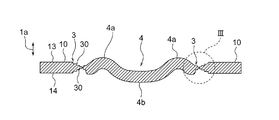
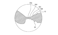
- FIG. 2 is a sectional view taken along line II-II in FIG. 1, and FIG. 3 is an enlarged view of region III in FIG.
- the annular thin portion 3 is constituted by a pair of recesses 30 formed on both the front surface 13 and the back surface 14 of the lid 1.
- the recesses 30 are formed by pressing the annular protrusions 23 provided so as to face each other simultaneously on both surfaces of the lid body 1 (see FIG. 4).
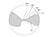
- the concave portion 30 includes a thinnest portion 30a having the thinnest thickness in the annular thin portion 3 and a thinnest portion 30a from the outer peripheral side plate surface 10.
- First to third step portions 30b to 30d that are gradually reduced in thickness are provided.
- the thinnest portion 30a and the first to third step portions 30b to 30d have a plurality of sets of annular protrusions 23 having different tip widths on both sides of the lid 1 in descending order of the tip width. It is formed by a plurality of coining processes (multi-stage coining) pressed simultaneously (see (a) to (d) of FIG. 4).
- the plurality of step portions 30b whose thickness is gradually reduced from the outer peripheral side plate surface 10 toward the thinnest portion 30a is provided in the concave portion 30, whereby the position of the thinnest portion 30a can be easily specified.
- the efficiency of quality inspection for inspecting the thickness of the annular thin portion 3 can be improved.
- the bent portion 4 is provided with a first protrusion 4a and a second protrusion 4b.
- the first protruding portion 4 a protrudes along the plate thickness direction 1 a from the surface 13 of the lid 1 on the outer peripheral side of the annular thin portion 3.
- the 2nd protrusion part 4b protrudes along the plate
- the bent portion 4 is formed by performing the above-described pressing while restraining the outer peripheral side plate surface 10, and absorbs the surplus due to the formation of the recess 30. Part.
- the bent portion 4 is formed in the inner peripheral portion of the annular thin portion 3, it is possible to avoid the surplus produced by the formation of the recess 30 from acting on the outer peripheral side plate surface 10, and the surplus is the lid. The influence on the external shape of 1 can be avoided. Further, since the bent portion 4 is formed in a corrugated cross section, the surface area of the bent portion 4 can be increased while suppressing the protrusion amount of the bent portion 4 with respect to the outer peripheral side plate surface 10.
- the internal pressure of the battery case in which the lid 1 is used can be increased and act on the safety valve 2. Moreover, since the protrusion amount of the bending part 4 with respect to the outer peripheral side plate surface 10 can be made small, possibility that another member will contact the bending part 4 can be made small, and possibility that the safety valve 2 will be damaged can be made low.
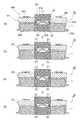
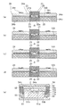
- FIG. 4 is a configuration diagram showing a safety valve manufacturing apparatus for manufacturing the safety valve 2 of FIG. 1, and FIGS. 4 (a) to 4 (d) show a safety valve manufacturing method using the safety valve manufacturing apparatus. 1 to 4 coining steps are shown.
- the safety valve manufacturing apparatus 20 includes a plurality of sets of punches 21 and dies 22 used in the first to fourth coining processes, and a plurality of sets of annular protrusions provided on the punches 21 and the dies 22. 23 and restraining means 24 provided on the side of each punch 21 and die 22 respectively.
- the annular protrusion 23 is a protrusion provided on each punch 21 and die 22 so as to face each other. Although only a cross section is shown in FIG. 4, the annular protrusion 23 extends from the central end surfaces 21 a and 22 a of the punch 21 and the die 22 so as to follow the shape of the annular thin portion 3 (see FIG. 1). It is formed in an annular shape along the outer edge. Each annular protrusion 23 has a different tip width for each set of punch 21 and die 22.
- a central recess 25 is formed on the inner peripheral side of the annular protrusion 23 in each punch 21 and die 22 with the annular protrusion 23 as a side wall and the central end surfaces 21a and 22a as bottom surfaces.
- the restraining means 24 has a blank holder 24a disposed on the side of the punch 21, a die holder 24b disposed on the side of the die 22, and an urging member 24c connected to the blank holder 24a.
- the blank holder 24 a and the biasing member 24 c are displaced integrally with the punch 21.
- the urging member 24c is constituted by, for example, a coil spring or the like, and urges the blank holder 24a toward the die holder 24b. That is, the restraining means 24 restrains (holds) the lid body 1 disposed between the punch 21 and the die 22 on the outer peripheral side of the annular protrusion 23 when the punch 21 is displaced toward the die 22. Is.
- the punch 21 and the die 22 provided with the annular protrusion 23 having the largest tip width are used, and the lid body 1 in the state where the side wall portion 11 and the flange portion 12 are provided is formed between the punch 21 and the die.
- the punch 21 is displaced toward the die 22.
- the annular protrusion 23 is simultaneously pressed against both surfaces (the front surface and the back surface 13, 14) of the lid body 1 while the lid body 1 is restrained by the restraining means 24 on the outer peripheral side of the annular protrusion 23.
- the first step 30b shown in FIG. 3 is formed by this first coining process.
- a surplus occurs due to the formation of the first step portion 30b.
- the surplus portion is the inner periphery of the first step portion 30b. Escape only to the side. That is, the surplus resulting from the formation of the first step portion 30b is bent and deformed in the central recess 25 of the punch 21 and the die 22 while the inner peripheral plate surface of the first step portion 30b is increased in thickness. By being absorbed. Thereby, it is possible to prevent the surplus generated by the formation of the first step portion 30b from acting on the outer peripheral plate surface of the first step portion 30b, and to prevent the outer shape of the lid body 1 from being deformed.
- the punch 21 and the die 22 provided with the annular protrusion 23 having a smaller tip width than the annular protrusion 23 used in the first coining process are used, and the bottom of the first step portion 30b is used.
- the second step portion 30c is formed by pressing the annular protrusion 23.
- the surplus thickness generated by the formation of the second step portion 30c is also absorbed by increasing the thickness and bending deformation of the inner peripheral plate surface of the second step portion 30c.
- the punch 21 and the die 22 provided with the annular protrusion 23 having a smaller tip width than the annular protrusion 23 used in the second coining process are used, and the second step 30c
- the third step portion 30d is formed by pressing the annular protrusion 23 against the bottom.
- the punch 21 and the die 22 provided with the annular protrusion 23 having a smaller tip width than the annular protrusion 23 used in the third coining process are used, and the bottom of the third step portion 30d is used.
- the thinnest portion 30a is formed by pressing the annular protrusion 23 against the thin film.
- the surplus portions generated by the formation of the third step portion 30d and the thinnest portion 30a are also absorbed by the increase in thickness and bending deformation of the inner peripheral side plate surfaces of the third step portion 30d and the thinnest portion 30a. .
- the lid body 1 is disposed between the punch 21 and the die 22, and the annular protrusions 23 provided on the punch 21 and the die 22 so as to face each other are disposed on the lid body 1.
- the annular thin portion 3 is formed on the lid body 1 by simultaneously pressing both sides. In this way, the annular thin portion 3 is formed by simultaneously pressing the annular protrusions 23 provided so as to face each other against both surfaces of the lid body 1. Compared with the case where the annular protrusion is pressed against one side of the body, the processing amount of the lid body 1 by one annular protrusion 23 can be reduced, and the processing load applied to one annular protrusion 23 can be reduced.
- the annular thin portion 3 when the annular thin portion 3 is formed using a stainless steel metal plate, cracking and work hardening during processing can be suppressed, so that the annular thin portion 3 can be formed with high accuracy and the processing load can be reduced by the punch 21 and the die. 22 and can extend the life of the mold. Further, since the thin annular portion 3 is formed by multi-stage coining in which a plurality of sets of annular protrusions 23 are pressed against both surfaces of the lid 1 in order of increasing tip width, the thinnest portion 30a and the first to third steps are formed on the annular thin portion 3. The portions 30b to 30d can be formed, and the quality inspection efficiency of the annular thin portion 3 can be improved by using the first to third step portions 30b to 30d.
- the present inventor uses the SUS430 steel plate having a nominal thickness of 0.8 mm as a material, and the first to second shown in FIG. 4 with respect to the lid body 1 in which the side wall portion 11 and the flange portion 12 are provided by pressing.
- the safety valve 2 was formed on the lid 1 by performing the 4 coining process.
- the shape of the annular thin portion 3 was an oval shape having a long side of 15 mm and a short side of 10 mm, and the thinnest portion 30a had a thickness of 0.015 mm.
- the punch 21 and the die 22 provided with the annular protrusion 23 having a tip width of 1.5 mm are used.
- the annular protrusion 23 having a tip width of 1.0 mm is provided.
- the punch 21 and the die 22 provided with the annular protrusion 23 having a tip width of 0.5 mm are used, and in the fourth coining process, the tip is 60 °.
- a punch 21 and a die 22 provided with an annular protrusion 23 having a triangular cross-section and a tip R of 0.2R were used. Further, through the first to fourth coining steps, the depth of the punch 21 and the central recess 25 of the die 22 was set to 0.8 mm, which is the nominal plate thickness.
- the crushing rate [%] of the lid body 1 in the first to fourth coining steps was changed as in Examples A to K shown in Table 1 below, and the crushing rate of the lid body 1 and the mold The relationship with damage was investigated.
- the crushing rate [%] indicates how much the plate surface of the lid 1 is crushed in each coining process, and ⁇ (plate thickness in the previous process ⁇ plate thickness in the subsequent process) ⁇ plate in the previous process Thickness ⁇ ⁇ 100.
- requiring the crushing rate of a 1st coining process is a nominal plate
- the crushing rate of the lid 1 in each coining step is preferably 70% or less.
- the safety valve 2 formed under the above-mentioned conditions provided a desired annular thin portion 3 without cracking, and operated stably in a pressure range of 0.6 to 0.8 MPa.
- the lid 1 made of a stainless steel metal plate is disposed between the punch 21 and the die 22, and the annular provided on the punch 21 and the die 22 so as to face each other. Since the annular thin portion 3 constituting the edge of the safety valve 2 is formed on the lid body 1 by simultaneously pressing the projections 23 on both sides of the lid body 1, an annular projection is formed on one side of the lid body as in the prior art. Compared with the case where the portion is pressed, the processing amount of the lid body 1 by the single annular protrusion 23 can be reduced, and the processing load applied to the single annular protrusion 23 can be reduced.
- the lid body 1 when the annular projection 23 is pressed against both surfaces of the lid body 1, the lid body 1 is restrained by the restraining means 24 on the outer peripheral side of the annular projection portion 23, so that a surplus generated when the annular thin portion 3 is formed. It is possible to escape only to the inner peripheral side of the annular protrusion 23, and it is possible to avoid that the surplus part affects the outer shape of the lid 1.
- annular thin portion is formed by a plurality of coining processes in which the annular protrusions 23 are pressed against both surfaces of the lid 1 in descending order of the tip width. 3 is formed, the processing load on one annular protrusion 23 can be further reduced, and the life of the mold can be further improved.
- a plurality of step portions 30b whose thickness is gradually reduced from the outer peripheral side plate surface 10 toward the thinnest portion 30a can be provided in the annular thin portion 3, and the thinnest portion 30a is utilized using the step portion 30b. Can be easily specified, and the efficiency of quality inspection for inspecting the thickness of the annular thin portion 3 can be improved.
- the crushing rate of the lid 1 in each coining step is set to 70% or less, the possibility that the punch 21 and the annular protrusion 23 of the die 22 are damaged can be further reduced, and the life of the mold can be more reliably ensured. Can be long.
- the stainless steel lid 1 constituting the battery case of the battery is restrained on the outer peripheral side of the annular protrusion 23 by the restraining means 24, and the lids are arranged in descending order of the tip width. Since the annular thin portion 3 constituting the edge of the safety valve 2 is formed in the lid body 1 by simultaneously pressing the annular protrusions against both surfaces of the battery 1, the above-described battery safety valve manufacturing method and Similarly, cracks and work hardening during processing can be suppressed when the annular thin portion 3 is formed while avoiding that a surplus generated when forming the annular thin portion 3 affects the outer shape of the lid 1. Therefore, the annular thin portion 3 can be molded with high accuracy, the processing load can be distributed to the punch 21 and the die 22, and the life of the mold can be extended.
- the annular thin portion 3 is formed by a pressing process in which the annular protrusions facing each other are simultaneously pressed against both surfaces of a stainless steel metal plate constituting the battery case of the battery. 1 is composed of a pair of concave portions formed on both surfaces, and the bent portion 4 is provided on the inner peripheral side of the annular thin portion 3 and is bent and deformed along the plate thickness direction by the action of press working.
- the safety valve 2 is formed, cracks during processing and work hardening can be suppressed, so that the annular thin portion 3 can be accurately formed and the processing load when forming the annular thin portion 3 is distributed to the punch 21 and the die 22. The life of the mold can be extended.
- the annular thin portion 3 includes a thinnest portion 30a having the smallest thickness in the annular thin portion 3, and a first thickness gradually reduced from the outer peripheral side plate surface 10 toward the thinnest portion 30a.
- the third step portions 30b to 30d are provided, the position of the thinnest portion 30a can be easily specified using the step portion 30b, and the efficiency of the quality inspection for inspecting the thickness of the annular thin portion 3 is improved. it can.
- FIG. FIG. 5 is a perspective view showing lid 1 of the battery case according to the second embodiment of the present invention.
- the lid 1 constituting the battery case of the secondary battery is provided with a safety valve 2 for the secondary battery that is opened when the internal pressure of the battery case exceeds a predetermined value to release the internal pressure to the outside.
- the safety valve 2 is provided with an annular thin portion 3 and a bent portion 4.
- the annular thin portion 3 is an oval groove that constitutes the edge of the safety valve 2, and is a portion that is thinner than the other plate surface in the lid 1.
- the annular thin portion 3 is torn first when the internal pressure of the battery case exceeds a predetermined value, and cleaves the entire safety valve 2.
- the outer shape of the annular thin portion 3 only needs to have a closed outer edge, and may be, for example, a perfect circle or a polygon.
- the bent portion 4 is a plate surface located on the inner peripheral side of the annular thin portion 3, and is a portion that is bent and deformed along the plate thickness direction 1 a of the lid 1.
- the outer peripheral plate surface of the annular thin portion 3 (hereinafter referred to as the outer peripheral plate surface 10) is formed flat. Side wall portions 11 bent substantially at right angles along the thickness direction 1a from the entire outer edge of the outer peripheral side plate surface 10 and flange portions 12 bent substantially at right angles from the tips of the side wall portions 11 are provided upright.
- the end surface of the lid body 1 in the direction in which the side wall portion 11 is erected is referred to as the front surface 13, and the end surface of the opposite lid body 1 is referred to as the back surface 14.
- the annular thin portion 3 is composed of a pair of recesses 30 formed on both the front surface 13 and the back surface 14 of the lid 1.
- the concave portion 30 is formed by pressing the annular protrusions 23 provided so as to face each other simultaneously on both surfaces of the stainless steel metal plate 100 that is the material of the lid 1. It is formed (see FIG. 9).
- the concave portion 30 includes a thinnest portion 30a having the smallest thickness in the annular thin portion 3, and a thinnest portion 30a from the outer peripheral side plate surface 10.
- First to third step portions 30b to 30d that are gradually reduced in thickness are provided.
- the thinnest portion 30a and the first to third step portions 30b to 30d have a plurality of sets of annular protrusions 23 having different tip widths on both sides of the lid 1 in descending order of the tip width. It is formed by multistage coining that is pressed simultaneously (see FIGS. 9A to 9D).
- the plurality of step portions 30b whose thickness is gradually reduced from the outer peripheral side plate surface 10 toward the thinnest portion 30a is provided in the concave portion 30, whereby the position of the thinnest portion 30a can be easily specified.
- the efficiency of quality inspection for inspecting the thickness of the annular thin portion 3 can be improved.
- the bent portion 4 is provided with a first protrusion 4a and a second protrusion 4b.
- the first protruding portion 4 a protrudes along the plate thickness direction 1 a from the surface 13 of the lid 1 on the outer peripheral side of the annular thin portion 3.
- the 2nd protrusion part 4b protrudes along the plate
- the bent portion 4 is formed in a cross-sectional waveform that is bent and deformed not only in one direction of the front surface direction or the back surface direction of the lid 1 but also in both the front surface direction and the back surface direction.
- the bent portion 4 is formed by performing the above-described pressing while restraining the outer peripheral side plate surface 10, and absorbs the surplus due to the formation of the recess 30. Part.
- the bent portion 4 in the inner peripheral portion of the annular thin portion 3, it is possible to reduce the surplus caused by the formation of the recess 30 from acting on the outer peripheral side plate surface 10, and the surplus is the lid.
- the influence on the outer shape of 1 is reduced.
- the bent portion 4 in a cross-sectional waveform the surface area of the bent portion 4 can be increased while suppressing the amount of protrusion of the bent portion 4 with respect to the outer peripheral plate surface 10.
- the internal pressure of the battery case in which the lid 1 is used can be increased and act on the safety valve 2. Moreover, since the protrusion amount of the bending part 4 with respect to the outer peripheral side plate surface 10 can be made small, possibility that another member will contact the bending part 4 can be made small, and possibility that the safety valve 2 will be damaged can be made low.
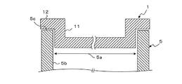
- FIG. 8 is an explanatory diagram showing the relationship between the lid 1 and the case body 5 of FIG.
- the case body 5 constitutes a battery case together with the lid 1 and is a stainless steel container formed in a bottomed cylindrical shape having an opening 5a.
- the lid 1 is inserted into the opening 5 a so that the outer surface of the side wall 11 extends along the inner peripheral surface 5 b of the case body 5.
- the lower surface of the flange portion 12 is overlaid on the upper end portion 5c of the case body 5 when the lid 1 is inserted into the opening 5a.
- the lid 1 and the case main body 5 are integrated by welding the lower surface of the flange portion 12 and the upper end portion 5c of the case main body 5 by, for example, laser welding.
- the bending portion 4 absorbs the surplus generated by the formation of the concave portion 30, but all the surplus surplus is absorbed by the bending portion 4. It is difficult to let When the surplus part acts on the outer peripheral side plate surface 10, elastic strain remains on the outer peripheral side plate surface 10 around the annular thin portion 3, and the lid body 1 is curved. When the curvature of the lid body 1 is large, a large gap is generated between the lower surface of the flange portion 12 shown in FIG. 8 and the upper end portion 5c of the case body 5, and it becomes difficult to weld the lid body 1 to the case body 5.
- the elastic strain can be removed and the curvature of the lid body 1 due to the elastic strain can be suppressed.
- FIG. 9 is a configuration diagram showing a lid manufacturing apparatus for manufacturing the lid 1 of FIG. 5, and FIGS. 9A to 9D are lid bodies using the lid manufacturing apparatus.
- the coining process of a manufacturing method is shown, (e) of FIG. 9 has shown the side wall formation process of a cover body manufacturing method.
- FIGS. 9A to 9D in the coining step, a plurality of sets of punches 21 and dies 22, a plurality of sets of annular protrusions 23 provided on each of the punches 21 and dies 22, and each punch Multistage coining is performed using the restraining means 24 provided on the side portions of the die 21 and the die 22, respectively.
- the annular protrusion 23 is a protrusion provided on each punch 21 and die 22 so as to face each other. Although only a cross section is shown in FIG. 9, the annular protrusion 23 extends from the center end surfaces 21 a and 22 a of the punch 21 and the die 22 so as to follow the shape of the annular thin portion 3 (see FIG. 5). It is formed in an annular shape along the outer edge. Each annular protrusion 23 has a different tip width for each set of punch 21 and die 22.
- a central recess 25 is formed on the inner peripheral side of the annular protrusion 23 in each punch 21 and die 22 with the annular protrusion 23 as a side wall and the central end surfaces 21a and 22a as bottom surfaces.
- the restraining means 24 has a blank holder 24a disposed on the side of the punch 21, a die holder 24b disposed on the side of the die 22, and an urging member 24c connected to the blank holder 24a.
- the blank holder 24 a and the biasing member 24 c are displaced integrally with the punch 21.
- the urging member 24c is constituted by, for example, a coil spring or the like, and urges the blank holder 24a toward the die holder 24b. That is, the restraining means 24 restrains (holds) the lid body 1 disposed between the punch 21 and the die 22 on the outer peripheral side of the annular protrusion 23 when the punch 21 is displaced toward the die 22. Is.
- the punch 51 As shown in FIG. 9E, in the side wall forming step, the punch 51, an annular die 52 disposed at the outer peripheral position of the punch 51, and an annular holder 53 disposed so as to face the die 52 , And restraining means 54 provided at the inner peripheral position of the die 52 are used.
- the punch 51, the die 52, and the holder 53 perform drawing processing on the metal plate 100 that is a material of the lid 1.
- a recess 51a disposed at a position corresponding to the safety valve 2 of the lid 1 and a support 51b surrounding the recess 51a are provided.
- the restraining means 54 is provided with a cushion pad 54a and an annular pressing body 54b attached to the cushion pad 54a.
- the cushion pad 54a is made of an elastic body such as urethane.
- the pressing body 54 b is made of metal and is formed in an annular shape so as to face the support portion 51 b of the punch 51.
- a punch 21 and a die 22 provided with an annular protrusion 23 having the largest tip width are used, and a flat metal serving as a material of the lid 1 is used.
- the punch 21 is displaced toward the die 22.
- the annular protrusion 23 is simultaneously pressed against both surfaces (front and back surfaces 13 and 14) of the metal plate 100 while the metal plate 100 is restrained by the restraining means 24 on the outer peripheral side of the annular protrusion 23.
- the first step 30b shown in FIG. 7 is formed by this first coining process.
- a surplus occurs due to the formation of the first step portion 30b.
- the metal plate 100 is restrained by the restraining means 24 on the outer peripheral side of the annular protrusion 23
- most of the surplus portion is the first step portion 30b. Escape to the inner circumference side of. That is, most of the surplus generated by the formation of the first step portion 30b is bent in the central recess 25 of the punch 21 and the die 22 while the inner peripheral plate surface of the first step portion 30b is increased in thickness. By being deformed, it is absorbed. Thereby, it is reduced that the surplus part produced by formation of the 1st step part 30b acts on the board surface of the outer peripheral side of the 1st step part 30b.
- the punch 21 and the die 22 provided with the annular protrusion 23 having a smaller tip width than the annular protrusion 23 used in the first coining process are used.
- the second protrusion 30c is formed by pressing the annular protrusion 23 against the bottom of the first protrusion 30b. Most of the surplus due to the formation of the second step portion 30c is absorbed by increasing the thickness and bending deformation of the inner peripheral plate surface of the second step portion 30c.
- the die 22 is used, and the third protrusion 30d is formed by pressing the annular protrusion 23 against the bottom of the second protrusion 30c.
- the die 22 is used, and the thinnest portion 30a is formed by pressing the annular protrusion 23 against the bottom of the third step portion 30d.
- the thickness of the annular protrusion 23 is reduced to the final target thickness.
- Most of the surplus due to the formation of the third step portion 30d and the thinnest portion 30a is largely increased by bending and deforming the inner peripheral side of the third step portion 30d and the thinnest portion 30a. Is absorbed.
- the annular thin portion 3 is formed by simultaneously pressing the annular protrusions 23 provided so as to face each other against both surfaces of the metal plate 100, so that the lid as in the prior art is formed.
- the processing amount of the metal plate 100 by one annular protrusion 23 can be reduced, and the processing load applied to one annular protrusion 23 can be reduced. That is, when the annular thin portion 3 is formed using a stainless steel metal plate, cracking and work hardening during processing can be suppressed, so that the annular thin portion 3 can be formed with high accuracy and the processing load can be reduced by the punch 21 and the die. 22 and can extend the life of the mold.
- the annular thin portion 3 is formed by multi-stage coining in which a plurality of sets of annular protrusions 23 are pressed against both surfaces of the metal plate 100 in order of increasing tip width, the thinnest portion 30a and the first to third steps are formed on the annular thin portion 3.
- the portions 30b to 30d can be formed, and the quality inspection efficiency of the annular thin portion 3 can be improved by using the first to third step portions 30b to 30d.
- the die 52 is lowered after the metal plate 100 is placed on the punch 51 so that the annular thin portion 3 is positioned inside the recess 51a.
- the metal plate 100 is drawn. That is, the metal plate 100 is bent according to the lowering of the die 52, and the side wall 11 is formed by extending the metal plate 100 between the inner peripheral surface of the die 52 and the outer peripheral surface of the punch 51. Is done.
- the die 52 is further lowered after the bent metal plate 100 is brought into contact with the holder 53, so that the metal plate 100 is bent along the holder 53 to form the flange portion 12.
- the surplus generated in the coining process as described above generates elastic strain on the outer peripheral side plate surface 10.
- tensile strain can be applied to the outer peripheral side plate surface 10 so as to cancel the elastic strain generated in the coining step.
- the elastic strain which arose in the coining process can be removed, and the curve of the lid body 1 due to the elastic strain can be suppressed.
- FIG. 9 (e) shows the final state of the drawing, but the mold used in the side wall forming step is ahead of the die 52 when the die 52 is lowered toward the punch 51.
- the pressing body 54 b is configured to come into contact with the metal plate 100.
- the outer peripheral side plate surface 10 around the annular thin portion 3 is restrained by the pressing body 54b and the support portion 51b while the cushion pad 54a is compressed.
- the annular thin part 3 may be broken.
- the annular thin portion 3 is avoided from being broken by drawing the metal plate 100 in a state where the outer peripheral side plate surface 10 around the annular thin portion 3 is restricted by the restraining means 54.
- 9 (e) shows that the entire outer peripheral side plate surface 10 is restrained, but only a narrower range around the annular thin portion 3 may be restrained.
- the inventor formed the lid 1 by performing the coining step and the side wall forming step shown in FIG. 9 using a SUS430 steel plate having a nominal thickness of 0.8 mm as a material.
- the shape of the annular thin portion 3 was an oval shape having a long side of 15 mm and a short side of 10 mm, and the thickness (final target thickness) of the thinnest portion 30a was 0.015 mm.
- a punch 21 and a die 22 provided with an annular protrusion 23 having a tip width of 1.5 mm are used.
- an annular protrusion having a tip width of 1.0 mm is used.
- the punch 21 and the die 22 provided with the annular protrusion 23 having a tip width of 0.5 mm are used.
- a punch 21 and a die 22 provided with an annular protrusion 23 having a triangular cross section with a tip of 60 ° and a tip R of 0.2R were used.
- the depth of the central recess 25 of the punch 21 and the die 22 was set to 0.8 mm, which is the nominal plate thickness.
- the crushing rate [%] of the lid 1 in the first to fourth stage coining is changed as in Examples A to K shown in Table 2 below, and the crushing rate of the metal plate 100 and the mold are changed.
- the relationship with the damage was investigated.
- the crushing rate [%] indicates how much the plate surface of the lid 1 is crushed in each coining process, and ⁇ (plate thickness in the previous process ⁇ plate thickness in the subsequent process) ⁇ plate in the previous process Thickness ⁇ ⁇ 100.
- requiring the crushing rate of a 1st coining process is a nominal plate
- the twist amount of the flange portion 12 may be about 0.5 mm, resulting in poor welding.
- the twist amount could be suppressed to 0.3 mm or less, and the occurrence of poor welding could be avoided.
- the annular thin portions 3 are formed by simultaneously pressing the annular protrusions 23 arranged opposite to each other on the front and back surfaces of the metal plate 100.
- the processing amount of the lid body 1 by one annular protrusion 23 can be reduced, and the processing load on one annular protrusion 23 can be reduced. it can.
- cracks during processing and work hardening can be suppressed, so that the annular thin portion can be formed with high accuracy, and the processing load can be distributed to the punch 21 and the die 22, and the life of the mold can be obtained. Can be lengthened.
- the metal plate 100 is drawn after the coining step to form the side wall portion 11 on the metal plate 100, tensile strain due to drawing can be applied to the plate surface on which elastic strain is generated by the coining step. . Thereby, the elastic strain which arose in the coining process can be removed, and the curve of the lid due to the elastic strain can be suppressed.
- the drawing is performed in a state where the outer peripheral side plate surface 10 around the annular thin portion 3 is restrained by the restraining means 54, so that it is avoided that the tensile stress in the drawing processing acts on the annular thin portion 3 greatly. This can avoid breakage of the annular thin portion 3.
- a plurality of annular protrusions 23 having different tip widths are used, and multi-stage coining is performed in which the annular protrusions 23 are pressed against the metal plate 100 in descending order of the tip width, so that the processing load applied to one annular protrusion 23 is increased.
- the life of the mold can be further improved.
- a plurality of step portions 30b whose thickness is gradually reduced from the outer peripheral side plate surface 10 toward the thinnest portion 30a can be provided in the annular thin portion 3, and the thinnest portion 30a is utilized using the step portion 30b. Can be easily specified, and the efficiency of quality inspection for inspecting the thickness of the annular thin portion 3 can be improved.
- FIG. 10 is an explanatory diagram showing a battery case lid manufacturing method according to Embodiment 3 of the present invention.
- the tensile stress on the annular thin portion 3 caused by the drawing is reduced. I am letting.
- the thickness of the annular thin portion 3 may decrease due to the tensile stress. If the thickness of the annular thin portion 3 is thinner than a predetermined thickness, the annular thin portion 3 is torn before the pressure in the battery case reaches a presumed pressure.
- the thickness of the annular thin portion 3 is reduced to the final target thickness in the coining step performed before the side wall forming step (see FIGS. 9A to 9D).
- the thickness of the annular thin portion 3 is stopped to be thicker than the final target thickness (FIGS. 10A to 10C).
- the annular thin portion 3 is pressed against the annular thin portion 3, thereby reducing the thickness of the annular thin portion 3 to the final target thickness. (See (e) of FIG. 10).
- the adjustment annular protrusion 26 the same one as the annular protrusion used in the fourth stage coining shown in FIG.
- the pushing amount of the annular protrusion is an amount that takes into account the thinning amount in the side wall forming step.
- Other configurations are the same as those of the second embodiment.
- the thickness of the annular thin portion 3 is reduced to the final target thickness by pressing the adjustment annular projection 26 against the annular thin portion 3 after the side wall forming step.
- the annular thin portion 3 can be formed in consideration of the thinning amount in the side wall forming step, and the accuracy of the thickness of the annular thin portion 3 can be improved. Thereby, the precision of the operating pressure of the safety valve 2 can be improved, and the reliability of the operation of the safety valve 2 can be improved.
- the metal plate 100 is drawn so as to form the flange portion 12 having an appropriate size. However, after drawing a larger metal plate, the metal plate 100 is drawn. The size of the flange portion may be adjusted by cutting off the excess area. That is, the side wall forming step may further include trimming processing of the metal plate.
- the annular protrusions 23 arranged so as to face each other are simultaneously pressed against both the front and back surfaces of the metal plate 100 to form the annular thin portion, but the present invention is not limited to this.
- the annular thin portion may be formed by pressing the annular protrusion only on one of the front and back surfaces of the metal plate.
Abstract
本発明は、電池ケース内の圧力が所定値を超えた場合に最先に裂けるべき部分である環状薄肉部を精度良く成形できるとともに、環状薄肉部を形成する際の加工負荷をパンチ及びダイに分散でき、金型の寿命を長くすることができる電池の安全弁製造方法、電池の安全弁製造装置、電池の安全弁、及び電池ケースの蓋体製造方法を提供することを解決しようとする課題とする。 本発明の電池の安全弁製造方法、電池の安全弁製造装置、電池の安全弁、及び電池ケースの蓋体製造方法は、互いに対向するようにパンチ(21)及びダイ(22)に設けられた環状突部(23)を、ステンレス鋼製の金属板(1)の両面に同時に押し付けて環状薄肉部を形成することにより、上記課題を解決した。
Description
本発明は、電池の安全弁製造方法、電池の安全弁製造装置、電池の安全弁、及び電池ケースの蓋体製造方法に関し、特に、ステンレス鋼製の金属板を用い、互いに対向するようにパンチ及びダイに設けられた環状突部を金属板の両面に同時に押し付けることにより、安全弁の縁部を構成する環状薄肉部を金属板に形成することで、環状薄肉部を精度良く成形できると共に、環状薄肉部を形成する際の加工負荷をパンチ及びダイに分散でき、金型の寿命を長くすることができるようにするための新規な改良に関するものである。
一般に、密閉した電池ケース内に電解液を収容する電池には、電池ケース内の圧力が上昇して爆発することを防止するために、電池ケース内の圧力が所定値を超えた場合に開裂して電池ケース内の圧力を外部へと開放する安全弁が設けられる。従来用いられているこの種の電池の安全弁製造方法としては、例えば下記の特許文献1等に示されている方法を挙げることができる。
すなわち、従来方法では、環状突部が形成された刻印パンチと平面状のダイとの間に電池用ケースの蓋体となる金属板を配置して、平面状のダイにより金属板を支持しつつ、刻印パンチの環状突部を金属板に押し当てることにより、安全弁の縁部を構成する環状薄肉部を金属板に形成している。電池ケース内の圧力が所定値を超えた場合、他の部分よりも肉厚が薄くされている環状薄肉部が裂けることにより、安全弁全体が開裂される。
上述のように、環状薄肉部は、電池ケース内の圧力が所定値を超えた場合に最先に裂けるべき部分であり、その肉厚は例えば0.010mm程度まで薄くされる。すなわち、このような環状薄肉部を形成するためのパンチ及びダイも極めて繊細なものである。
上記のような従来の電池の安全弁製造方法では、平面状のダイにより金属板を支持しつつ、刻印パンチの環状突部を金属板に押し当てることにより、環状薄肉部を金属板に形成する構成であるので、実質的に刻印パンチの環状突部のみで金属を変形させて環状薄肉部を形成している。
従来、安全弁を成形する金属板にはアルミニウム等の軟質金属が使用されていたが、近年では、電池用ケースの耐食性や強度を向上させるために、ステンレス鋼を用いることが提案されている。
金属板がアルミニウムの場合、軟質であるため環状薄肉部を精度良く加工でき、また金型への負荷も小さいため、問題なく加工できていたが、ステンレス鋼の場合は、強度が高く硬質の材料であるため、安全弁の環状薄肉部を従来方法により加工しようとすると、加工中に割れが発生し易く、また加工硬化により薄肉部を精度良く加工できないという問題がある。
さらに、従来方法には、環状薄肉部を形成する際の負荷が刻印パンチの環状突部に集中してしまうため、金型の寿命が短くなるという問題もある。
本発明は、上記のような課題を解決するためになされたものであり、その目的は、環状薄肉部を精度良く成形できると共に、環状薄肉部を形成する際の加工負荷をパンチ及びダイに分散でき、金型の寿命を長くすることができる電池の安全弁製造方法、電池の安全弁製造装置、電池の安全弁、及び電池ケースの蓋体製造方法を提供することである。
本発明に係る電池の安全弁製造方法は、電池の電池ケースを構成するステンレス鋼製の金属板をパンチとダイとの間に配置して、互いに対向するようにパンチ及びダイに設けられた環状突部を金属板の両面に同時に押し付けることにより、安全弁の縁部を構成する環状薄肉部を金属板に形成することを特徴とする。
本発明に係る電池の安全弁製造装置は、複数組のパンチ及びダイと、互いに対向するようにパンチ及びダイに設けられ、パンチ及びダイの組毎に異なる先端幅を有する複数組の環状突部と、各パンチ及びダイの環状突部の外周側に配置された拘束手段とを備え、電池の電池ケースを構成するステンレス鋼製の金属板を拘束手段により環状突部の外周側において拘束しつつ、先端幅が大きな順に金属板の両面に対して環状突部を同時に押し付けることにより、安全弁の縁部を構成する環状薄肉部を金属板に形成するように構成されている。
本発明に係る電池の安全弁は、互いに対向する環状突部が電池の電池ケースを構成するステンレス鋼製の金属板の両面に同時に押し当てられるプレス加工により、金属板の両面に形成された一対の凹部からなる環状薄肉部と、環状薄肉部の内周側に設けられ、プレス加工の作用により板厚方向に沿って曲げ変形されている屈曲部とを備える。
本発明に係る電池ケースの蓋体製造方法では、環状薄肉部により縁部が構成された安全弁と、環状薄肉部の外周側に位置する外周側板面の外縁から環状に立設された側壁部とを有する電池ケースの蓋体を製造するための電池ケースの蓋体製造方法であって、蓋体の素材であるステンレス鋼製の金属板に環状突部を押し付けることにより、金属板に環状薄肉部を形成するコイニング工程と、コイニング工程の後に金属板に絞り加工を施して、金属板に側壁部を形成する側壁形成工程とを含み、コイニング工程では、互いに対向して配置された環状突部を金属板の表裏両面に同時に押し付けることにより環状薄肉部を形成する。
本発明の電池の安全弁製造方法、電池の安全弁製造装置、電池の安全弁、及び電池ケースの蓋体製造方法によれば、互いに対向するようにパンチ及びダイに設けられた環状突部をステンレス鋼製の金属板の両面に同時に押し付けることにより、安全弁の縁部を構成する環状薄肉部を金属板に形成するので、1つの環状突部による金属板の加工量を小さくでき、1つの環状突部に掛る加工負荷を小さくできる。すなわち、加工中の割れや加工硬化を抑制できるため、環状薄肉部を精度良く成形できると共に、環状薄肉部を形成する際の加工負荷をパンチ及びダイに分散でき、金型の寿命を長くすることができる。
以下、本発明を実施するための形態について、図面を参照して説明する。
実施の形態1.
図1は本発明の実施の形態1による二次電池の安全弁2を示す斜視図である。図において、蓋体1は、ステンレス鋼製の金属板からなり、二次電池の電池ケースを構成するものである。この蓋体1には、電池ケースの内部圧力が所定値を超えた場合に開裂して内部圧力を外部に開放する二次電池の安全弁2が設けられている。この安全弁2には、環状薄肉部3と屈曲部4とが設けられている。
実施の形態1.
図1は本発明の実施の形態1による二次電池の安全弁2を示す斜視図である。図において、蓋体1は、ステンレス鋼製の金属板からなり、二次電池の電池ケースを構成するものである。この蓋体1には、電池ケースの内部圧力が所定値を超えた場合に開裂して内部圧力を外部に開放する二次電池の安全弁2が設けられている。この安全弁2には、環状薄肉部3と屈曲部4とが設けられている。
環状薄肉部3は、安全弁2の縁部を構成する長円形の溝であり、蓋体1内の他の板面に比して肉厚が薄くされている部分である。この環状薄肉部3は、電池ケースの内部圧力が所定値を超えた場合に最先に裂けて、安全弁2全体を開裂させるものである。なお、環状薄肉部3の外形は、閉じられた外縁を有するものであればよく、例えば真円形や多角形等でもよい。屈曲部4は、環状薄肉部3の内周側に位置する板面であり、蓋体1の板厚方向1aに沿って蓋体1の板厚方向1aに沿って曲げ変形された部分である。
環状薄肉部3の外周側の蓋体1の板面(以下、外周側板面10と呼ぶ)は、平坦に形成されている。外周側板面10の外縁には、外周側板面10から板厚方向1aに沿って立設された側壁部11が設けられており、側壁部11の先端には、側壁部11から略直角に屈曲されたフランジ部12が設けられている。これ以降、側壁部11が立設された方向の蓋体1の端面を表面13と呼び、逆側の蓋体1の端面を裏面14と呼ぶ。
次に、図2は図1の線II-IIに沿う断面図であり、図3は図2の領域IIIの拡大図である。図2に示すように、環状薄肉部3は、蓋体1の表面13及び裏面14の両面に形成された一対の凹部30によって構成されている。後に図を用いて詳しく説明するが、凹部30は、互いに対向するように設けられた環状突部23を蓋体1の両面に同時に押し付けるプレス加工により形成されるものである(図4参照)。
凹部30についてより詳細に見ると、凹部30には、図3に示すように、環状薄肉部3内において肉厚が最も薄くされた最薄部30aと、外周側板面10から最薄部30aに向けて徐々に肉厚が薄くされた第1~第3段部30b~30dとが設けられている。後に図を用いて詳しく説明するが、最薄部30a及び第1~第3段部30b~30dは、先端幅が異なる複数組の環状突部23が先端幅の大きな順に蓋体1の両面に同時に押し付けられる複数のコイニング工程(多段コイニング)により形成される(図4の(a)~(d)参照)。このように、外周側板面10から最薄部30aに向けて徐々に肉厚が薄くされた複数の段部30bが凹部30に設けられることで、最薄部30aの位置を容易に特定でき、環状薄肉部3の厚みを検査する品質検査の効率を向上できるようにされている。
図2に戻り、屈曲部4には、第1突出部4aと第2突出部4bとが設けられている。第1突出部4aは、環状薄肉部3の外周側における蓋体1の表面13よりも板厚方向1aに沿って突出されている。第2突出部4bは、環状薄肉部3の外周側における蓋体1の裏面14よりも板厚方向1aに沿って突出されている。すなわち、屈曲部4は、蓋体1の表面方向又は裏面方向の一方向にだけでなく、表面方向及び裏面方向の両方向に向けて曲げ変形された断面波形に形成されている。後に図を用いて詳しく説明するが、屈曲部4は、外周側板面10を拘束しつつ前述のプレス加工が行われることで形成されるものであり、凹部30の形成により生じる肉余りを吸収した部分である。このように、環状薄肉部3の内周部に屈曲部4が形成されることで、凹部30の形成により生じる肉余りが外周側板面10に作用することを回避でき、当該肉余りが蓋体1の外形に影響を及ぼすことを回避できる。また、屈曲部4が断面波形に形成されることで、外周側板面10に対する屈曲部4の突出量を小さく抑えつつ、屈曲部4の表面積を大きくできる。屈曲部4の表面積を大きくすることで、蓋体1が用いられる電池ケースの内部圧力をより大きく安全弁2に作用させることができる。また、外周側板面10に対する屈曲部4の突出量を小さくできることで、他の部材が屈曲部4に接する可能性を小さくでき、安全弁2が破損する可能性を低くできる。
次に、図4は、図1の安全弁2を製造するための安全弁製造装置を示す構成図であり、図4の(a)~(d)はその安全弁製造装置を用いた安全弁製造方法の第1~第4コイニング工程を示している。図4に示すように、安全弁製造装置20は、第1~第4コイニング工程でそれぞれ用いられる複数組のパンチ21及びダイ22と、各パンチ21及びダイ22に設けられた複数組の環状突部23と、各パンチ21及びダイ22の側部にそれぞれ設けられた拘束手段24とを有している。
環状突部23は、互いに対向するように各パンチ21及びダイ22に設けられた突起体である。図4では断面しか示さないが、環状突部23は、環状薄肉部3(図1参照)の形状に沿うように、各パンチ21及びダイ22の中央端面21a,22aからパンチ21及びダイ22の外縁に沿って環状に形成されている。各環状突部23は、パンチ21及びダイ22の組毎に異なる先端幅を有している。各パンチ21及びダイ22における環状突部23の内周側には、環状突部23を側壁とし中央端面21a,22aを底面とする中央凹部25が形成されている。
拘束手段24は、パンチ21の側部に配置されたブランクホルダ24aと、ダイ22の側部に配置されたダイホルダ24bと、ブランクホルダ24aに接続された付勢部材24cとを有している。ブランクホルダ24a及び付勢部材24cは、パンチ21と一体に変位される。付勢部材24cは、例えばコイルバネ等により構成されており、ブランクホルダ24aをダイホルダ24bに向けて付勢するものである。すなわち、拘束手段24は、パンチ21がダイ22に向けて変位された際に、パンチ21とダイ22との間に配置された蓋体1を環状突部23の外周側において拘束(挟持)するものである。
次に、図4の安全弁製造装置を用いた安全弁製造方法について説明する。図1~図3に示す安全弁2を蓋体1に形成する場合、図4の(a)~(d)に示す第1~第4コイニング工程を順に行う。
第1コイニング工程では、最も大きな先端幅を有する環状突部23が設けられたパンチ21及びダイ22が用いられ、側壁部11及びフランジ部12が設けられた状態の蓋体1がパンチ21とダイ22との間に配置された後に、パンチ21がダイ22に向けて変位される。これにより、環状突部23の外周側において蓋体1が拘束手段24により拘束されつつ、蓋体1の両面(表面及び裏面13,14)に対して環状突部23が同時に押付けられる。
この第1コイニング工程により、図3に示す第1段部30bが形成される。ここで、第1段部30bの形成により肉余りが生じるが、環状突部23の外周側において蓋体1が拘束手段24により拘束されているので、肉余りは第1段部30bの内周側にのみ逃げる。すなわち、第1段部30bの形成により生じた肉余りは、第1段部30bの内周側の板面が、増肉されつつ、パンチ21及びダイ22の中央凹部25内で曲げ変形されることで、吸収される。これにより、第1段部30bの形成により生じた肉余りが第1段部30bの外周側の板面に作用することが防止され、蓋体1の外形が変形することを防止できる。
第2コイニング工程では、第1コイニング工程で用いられた環状突部23よりも小さな先端幅の環状突部23が設けられたパンチ21及びダイ22が用いられ、第1段部30bの底部に対して環状突部23が押付けられることで第2段部30cが形成される。この第2段部30cの形成により生じる肉余りについても、第2段部30cの内周側の板面が増肉及び曲げ変形されることで吸収される。
同様に、第3コイニング工程では、第2コイニング工程で用いられた環状突部23よりも小さな先端幅の環状突部23が設けられたパンチ21及びダイ22が用いられ、第2段部30cの底部に対して環状突部23が押付けられることで第3段部30dが形成される。また、第4コイニング工程では、第3コイニング工程で用いられた環状突部23よりも小さな先端幅の環状突部23が設けられたパンチ21及びダイ22が用いられ、第3段部30dの底部に対して環状突部23が押付けられることで最薄部30aが形成される。これら第3段部30d及び最薄部30aの形成により生じる肉余りについても、第3段部30d及び最薄部30aの内周側の板面が増肉及び曲げ変形されることで吸収される。
すなわち、第1~第4コイニング工程を通して、蓋体1をパンチ21とダイ22との間に配置して、互いに対向するようにパンチ21及びダイ22に設けられた環状突部23を蓋体1の両面に同時に押し付けることにより、環状薄肉部3を蓋体1に形成される。このように、互いに対向するように設けられた環状突部23を蓋体1の両面に対して同時に押し付けることにより環状薄肉部3が形成されるように構成することで、従来技術のように蓋体の片面に対して環状突部を押し付ける場合に比べて、1つの環状突部23による蓋体1の加工量を小さくでき、1つの環状突部23に掛る加工負荷を小さくできる。すなわち、ステンレス鋼製の金属板を用いて環状薄肉部3を形成する際、加工中の割れや加工硬化を抑制できるため、環状薄肉部3を精度良く成形できると共に、加工負荷をパンチ21及びダイ22に分散でき、金型の寿命を長くすることができる。また、先端幅が大きな順に複数組の環状突部23を蓋体1の両面に押し付ける多段コイニングにより環状薄肉部3を形成するので、環状薄肉部3に最薄部30a及び第1~第3段部30b~30dを形成でき、第1~第3段部30b~30dを利用して環状薄肉部3の品質検査の効率を向上できる。
次に、実施例を挙げる。本発明者は、公称板厚0.8mmのSUS430の鋼板を素材として、プレス加工により側壁部11及びフランジ部12が設けられた状態の蓋体1に対して、図4に示す第1~第4コイニング工程を施すことで、安全弁2を蓋体1に形成した。なお、環状薄肉部3の形状は長辺を15mmとし短辺を10mmとする長円形とし、最薄部30aの肉厚は0.015mmとした。また、第1コイニング工程では、先端幅が1.5mmの環状突部23が設けられたパンチ21及びダイ22を用い、第2コイニング工程では、先端幅が1.0mmの環状突部23が設けられたパンチ21及びダイ22を用い、第3コイニング工程では、先端幅が0.5mmの環状突部23が設けられたパンチ21及びダイ22を用い、第4コイニング工程では、先端が60°の三角断面形状で先端Rを0.2Rとした環状突部23が設けられたパンチ21及びダイ22を用いた。さらに、第1~第4コイニング工程を通して、パンチ21及びダイ22の中央凹部25の深さは、公称板厚分の0.8mmとした。
このような条件において、第1~第4コイニング工程における蓋体1の潰し率[%]を下記の表1に示す実施例A~Kように変更し、蓋体1の潰し率と金型の破損との関係を調べた。なお、潰し率[%]とは、各コイニング工程において蓋体1の板面をどの程度潰すかを示すものであり、{(前工程の板厚-後工程の板厚)÷前工程の板厚}×100で求められる数値である。なお、第1コイニング工程の潰し率を求めるときの前工程の板厚は、素材として用いられる鋼板の公称板厚である。

表1の実施例A,E~H,J,Kに示すように、潰し率を70%以下に抑えてコイニング工程を実施したところ、2000ショット後にもパンチ21及びダイ22の環状突部23にクラックは発生しないことが確認できた。これに対して、実施例B~D,Iに示すように、蓋体1の潰し率が70%を超えるコイニング工程を含む多段コイニングを実施すると、実施回数が2000ショットに届く前に、潰し率が70%を超えるコイニング工程のタイミングでパンチ21の環状突部23にクラックが発生することが判明した。従って、各コイニング工程における蓋体1の潰し率は70%以下とすることが好ましい。なお、上述の条件にて形成した安全弁2は、割れが発生することなく所望の環状薄肉部3が得られ、0.6~0.8MPaの圧力範囲で安定して作動した。
このような電池の安全弁製造方法では、ステンレス鋼製の金属板からなる蓋体1をパンチ21とダイ22との間に配置して、互いに対向するようにパンチ21及びダイ22に設けられた環状突部23を蓋体1の両面に同時に押し付けることにより、安全弁2の縁部を構成する環状薄肉部3を蓋体1に形成するので、従来技術のように蓋体の片面に対して環状突部を押し付ける場合に比べて、1つの環状突部23による蓋体1の加工量を小さくでき、1つの環状突部23に掛る加工負荷を小さくできる。これにより、環状薄肉部3を形成する際、加工中の割れや加工硬化を抑制できるため、環状薄肉部を精度良く成形できると共に、加工負荷をパンチ21及びダイ22に分散でき、金型の寿命を長くすることができる。
また、環状突部23を蓋体1の両面に押し付ける際に、環状突部23の外周側において拘束手段24により蓋体1を拘束するので、環状薄肉部3を形成する際に生じる肉余りを環状突部23の内周側のみに逃がすことができ、当該肉余りが蓋体1の外形に影響を及ぼすことを回避できる。
さらに、パンチ21及びダイ22の組毎に先端幅が異なる複数組の環状突部23を用い、先端幅が大きな順に蓋体1の両面に環状突部23を押し付ける複数のコイニング工程により環状薄肉部3を形成するので、1つの環状突部23に掛る加工負荷をさらに小さくでき、金型の寿命をさらに向上できる。また、外周側板面10から最薄部30aに向けて徐々に肉厚が薄くされた複数の段部30bを環状薄肉部3に設けることができ、この段部30bを利用して最薄部30aの位置を容易に特定でき、環状薄肉部3の厚みを検査する品質検査の効率を向上できる。
さらにまた、各コイニング工程における蓋体1の潰し率を70%以下とするので、パンチ21及びダイ22の環状突部23に破損が生じる可能性をさらに低減でき、金型の寿命をより確実に長くできる。
また、このような電池の安全弁製造装置では、電池の電池ケースを構成するステンレス鋼製の蓋体1を拘束手段24により環状突部23の外周側において拘束しつつ、先端幅が大きな順に蓋体1の両面に対して環状突部を同時に押し付けることにより、安全弁2の縁部を構成する環状薄肉部3を蓋体1に形成するように構成されているので、上述の電池の安全弁製造方法と同様に、環状薄肉部3を形成する際に生じる肉余りが蓋体1の外形に影響を及ぼすことを回避しつつ、環状薄肉部3を形成する際、加工中の割れや加工硬化を抑制できるため、環状薄肉部3を精度良く成形できると共に、加工負荷をパンチ21及びダイ22に分散でき、金型の寿命を長くすることができる。
また、このような電池の安全弁2では、環状薄肉部3は、互いに対向する環状突部が電池の電池ケースを構成するステンレス鋼製の金属板の両面に同時に押し当てられるプレス加工により、蓋体1の両面に形成された一対の凹部から構成され、屈曲部4は、環状薄肉部3の内周側に設けられ、プレス加工の作用により板厚方向に沿って曲げ変形されているので、当該安全弁2を形成する際に、加工中の割れや加工硬化を抑制できるため、環状薄肉部3を精度良く成形できると共に、環状薄肉部3を形成する際の加工負荷をパンチ21及びダイ22に分散でき、金型の寿命を長くすることができる。
また、環状薄肉部3には、環状薄肉部3内において肉厚が最も薄くされた最薄部30aと、外周側板面10から最薄部30aに向けて徐々に肉厚が薄くされた第1及び第3段部30b~30dとが設けられているので、段部30bを利用して最薄部30aの位置を容易に特定でき、環状薄肉部3の厚みを検査する品質検査の効率を向上できる。
実施の形態2.
図5は、本発明の実施の形態2による電池ケースの蓋体1を示す斜視図である。図において、二次電池の電池ケースを構成する蓋体1には、電池ケースの内部圧力が所定値を超えた場合に開裂して内部圧力を外部に開放する二次電池の安全弁2が設けられている。この安全弁2には、環状薄肉部3と屈曲部4とが設けられている。
図5は、本発明の実施の形態2による電池ケースの蓋体1を示す斜視図である。図において、二次電池の電池ケースを構成する蓋体1には、電池ケースの内部圧力が所定値を超えた場合に開裂して内部圧力を外部に開放する二次電池の安全弁2が設けられている。この安全弁2には、環状薄肉部3と屈曲部4とが設けられている。
環状薄肉部3は、安全弁2の縁部を構成する長円形の溝であり、蓋体1内の他の板面に比して肉厚が薄くされている部分である。この環状薄肉部3は、電池ケースの内部圧力が所定値を超えた場合に最先に裂けて、安全弁2全体を開裂させるものである。なお、環状薄肉部3の外形は、閉じられた外縁を有するものであればよく、例えば真円形や多角形等でもよい。屈曲部4は、環状薄肉部3の内周側に位置する板面であり、蓋体1の板厚方向1aに沿って曲げ変形された部分である。
環状薄肉部3の外周側の板面(以下、外周側板面10と呼ぶ)は、平坦に形成されている。外周側板面10の外縁全体から板厚方向1aに沿って略直角に屈曲された側壁部11と、側壁部11の先端から略直角に屈曲されたフランジ部12とが立設されている。これ以降、側壁部11が立設された方向の蓋体1の端面を表面13と呼び、逆側の蓋体1の端面を裏面14と呼ぶ。
次に、図6は図5の線VI-VIに沿う断面図であり、図7は図6の領域VIIの拡大図である。図6に示すように、環状薄肉部3は、蓋体1の表面13及び裏面14の両面に形成された一対の凹部30によって構成されている。後に図を用いて詳しく説明するが、凹部30は、互いに対向するように設けられた環状突部23を、蓋体1の素材であるステンレス鋼製の金属板100の両面に同時に押し付けるプレス加工により形成されるものである(図9参照)。
凹部30についてより詳細に見ると、凹部30には、図7に示すように、環状薄肉部3内において肉厚が最も薄くされた最薄部30aと、外周側板面10から最薄部30aに向けて徐々に肉厚が薄くされた第1~第3段部30b~30dとが設けられている。後に図を用いて詳しく説明するが、最薄部30a及び第1~第3段部30b~30dは、先端幅が異なる複数組の環状突部23が先端幅の大きな順に蓋体1の両面に同時に押し付けられる多段コイニングにより形成される(図9の(a)~(d)参照)。このように、外周側板面10から最薄部30aに向けて徐々に肉厚が薄くされた複数の段部30bが凹部30に設けられることで、最薄部30aの位置を容易に特定でき、環状薄肉部3の厚みを検査する品質検査の効率を向上できるようにされている。
図6に戻り、屈曲部4には、第1突出部4aと第2突出部4bとが設けられている。第1突出部4aは、環状薄肉部3の外周側における蓋体1の表面13よりも板厚方向1aに沿って突出されている。第2突出部4bは、環状薄肉部3の外周側における蓋体1の裏面14よりも板厚方向1aに沿って突出されている。すなわち、屈曲部4は、蓋体1の表面方向又は裏面方向の一方向にだけでなく、表面方向及び裏面方向の両方向に向けて曲げ変形された断面波形に形成されている。後に図を用いて詳しく説明するが、屈曲部4は、外周側板面10を拘束しつつ前述のプレス加工が行われることで形成されるものであり、凹部30の形成により生じる肉余りを吸収した部分である。このように、環状薄肉部3の内周部に屈曲部4が形成されることで、凹部30の形成により生じる肉余りが外周側板面10に作用することを低減でき、当該肉余りが蓋体1の外形に影響を及ぼすこと小さくしている。また、屈曲部4が断面波形に形成されることで、外周側板面10に対する屈曲部4の突出量を小さく抑えつつ、屈曲部4の表面積を大きくできる。屈曲部4の表面積を大きくすることで、蓋体1が用いられる電池ケースの内部圧力をより大きく安全弁2に作用させることができる。また、外周側板面10に対する屈曲部4の突出量を小さくできることで、他の部材が屈曲部4に接する可能性を小さくでき、安全弁2が破損する可能性を低くできる。
次に、図8は、図5の蓋体1とケース本体5との関係を示す説明図である。図8では概略的に示しているが、ケース本体5は、蓋体1とともに電池ケースを構成するものであり、開口部5aを有する有底筒状に形成されたステンレス鋼製の容器である。蓋体1は、側壁部11の外面がケース本体5の内周面5bに沿うように開口部5aに挿入される。ケース本体5の上端部5cには、蓋体1が開口部5aに挿入された際にフランジ部12の下面が重ねられる。蓋体1及びケース本体5は、例えばレーザ溶接等により、フランジ部12の下面とケース本体5の上端部5cとが溶接されることにより一体化される。
ここで、前述のように外周側板面10を拘束しつつプレス加工を行うことで凹部30の形成により生じる肉余りを屈曲部4で吸収させているが、すべての肉余りを屈曲部4に吸収させることは難しい。肉余りが外周側板面10に作用すると、環状薄肉部3周辺の外周側板面10に弾性ひずみが残留し、蓋体1が湾曲してしまう。蓋体1の湾曲が大きいと、図8に示すフランジ部12の下面とケース本体5の上端部5cとの間に大きな隙間が生じ、ケース本体5への蓋体1の溶接が困難となる。本実施の形態では、以下に説明する製造方法により蓋体1を製造することで、弾性ひずみを除去でき、弾性ひずみによる蓋体1の湾曲を抑えることができるようにしている。
次に、図9は、図5の蓋体1を製造するための蓋体製造装置を示す構成図であり、図9の(a)~(d)はその蓋体製造装置を用いた蓋体製造方法のコイニング工程を示し、図9の(e)は蓋体製造方法の側壁形成工程を示している。図9の(a)~(d)に示すように、コイニング工程では、複数組のパンチ21及びダイ22と、各パンチ21及びダイ22に設けられた複数組の環状突部23と、各パンチ21及びダイ22の側部にそれぞれ設けられた拘束手段24とを用いての多段コイニングが行われる。
環状突部23は、互いに対向するように各パンチ21及びダイ22に設けられた突起体である。図9では断面しか示さないが、環状突部23は、環状薄肉部3(図5参照)の形状に沿うように、各パンチ21及びダイ22の中央端面21a,22aからパンチ21及びダイ22の外縁に沿って環状に形成されている。各環状突部23は、パンチ21及びダイ22の組毎に異なる先端幅を有している。各パンチ21及びダイ22における環状突部23の内周側には、環状突部23を側壁とし中央端面21a,22aを底面とする中央凹部25が形成されている。
拘束手段24は、パンチ21の側部に配置されたブランクホルダ24aと、ダイ22の側部に配置されたダイホルダ24bと、ブランクホルダ24aに接続された付勢部材24cとを有している。ブランクホルダ24a及び付勢部材24cは、パンチ21と一体に変位される。付勢部材24cは、例えばコイルバネ等により構成されており、ブランクホルダ24aをダイホルダ24bに向けて付勢するものである。すなわち、拘束手段24は、パンチ21がダイ22に向けて変位された際に、パンチ21とダイ22との間に配置された蓋体1を環状突部23の外周側において拘束(挟持)するものである。
図9の(e)に示すように、側壁形成工程では、パンチ51と、パンチ51の外周位置に配置された環状のダイ52と、ダイ52に対向するように配置された環状のホルダ53と、ダイ52の内周位置に設けられた拘束手段54とが用いられる。パンチ51、ダイ52、ホルダ53は、蓋体1の素材である金属板100に絞り加工を施すものである。パンチ51の上部には、蓋体1の安全弁2に対応する位置に配置された凹部51aと、凹部51aを囲む支持部51bとが設けられている。
拘束手段54には、クッションパッド54aと、クッションパッド54aに取付けられた環状の押圧体54bが設けられている。クッションパッド54aは、例えばウレタン等の弾性体により構成されている。押圧体54bは、金属により構成されており、パンチ51の支持部51bに対向するように環状に形成されている。
次に、図9の蓋体製造装置を用いた蓋体製造方法について説明する。図5~図8に示す蓋体1に形成する場合、図9の(a)~(d)に示すコイニング工程を行った後に、図9の(e)に示す側壁形成工程を行う。
図9の(a)に示す第1段目のコイニングでは、最も大きな先端幅を有する環状突部23が設けられたパンチ21及びダイ22が用いられ、蓋体1の素材となる平板状の金属板100がパンチ21とダイ22との間に配置された後に、パンチ21がダイ22に向けて変位される。これにより、環状突部23の外周側において金属板100が拘束手段24により拘束されつつ、金属板100の両面(表面及び裏面13,14)に対して環状突部23が同時に押付けられる。
この第1コイニング工程により、図7に示す第1段部30bが形成される。ここで、第1段部30bの形成により肉余りが生じるが、環状突部23の外周側において金属板100が拘束手段24により拘束されているので、肉余りの大部分は第1段部30bの内周側に逃げる。すなわち、第1段部30bの形成により生じた肉余りの大部分は、第1段部30bの内周側の板面が、増肉されつつ、パンチ21及びダイ22の中央凹部25内で曲げ変形されることで、吸収される。これにより、第1段部30bの形成により生じた肉余りが第1段部30bの外周側の板面に作用することが低減される。
図9の(b)に示す第2段目のコイニングでは、第1コイニング工程で用いられた環状突部23よりも小さな先端幅の環状突部23が設けられたパンチ21及びダイ22が用いられ、第1段部30bの底部に対して環状突部23が押付けられることで第2段部30cが形成される。この第2段部30cの形成により生じる肉余りについても、第2段部30cの内周側の板面が増肉及び曲げ変形されることで、大部分が吸収される。
同様に、図9の(c)に示す第3段目のコイニングでは、第2段目のコイニングで用いられた環状突部23よりも小さな先端幅の環状突部23が設けられたパンチ21及びダイ22が用いられ、第2段部30cの底部に対して環状突部23が押付けられることで第3段部30dが形成される。また、図9の(d)に示す第4段目のコイニングでは、第3段目のコイニング工程で用いられた環状突部23よりも小さな先端幅の環状突部23が設けられたパンチ21及びダイ22が用いられ、第3段部30dの底部に対して環状突部23が押付けられることで最薄部30aが形成される。すなわち、第4段目のコイニングにて、環状突部23の肉厚が最終目標肉厚まで薄くされる。これら第3段部30d及び最薄部30aの形成により生じる肉余りについても、第3段部30d及び最薄部30aの内周側の板面が増肉及び曲げ変形されることで、大部分が吸収される。
このように、互いに対向するように設けられた環状突部23を金属板100の両面に対して同時に押し付けることにより環状薄肉部3が形成されるように構成することで、従来技術のように蓋体の片面に対して環状突部を押し付ける場合に比べて、1つの環状突部23による金属板100の加工量を小さくでき、1つの環状突部23に掛る加工負荷を小さくできる。すなわち、ステンレス鋼製の金属板を用いて環状薄肉部3を形成する際、加工中の割れや加工硬化を抑制できるため、環状薄肉部3を精度良く成形できると共に、加工負荷をパンチ21及びダイ22に分散でき、金型の寿命を長くすることができる。
また、先端幅が大きな順に複数組の環状突部23を金属板100の両面に押し付ける多段コイニングにより環状薄肉部3を形成するので、環状薄肉部3に最薄部30a及び第1~第3段部30b~30dを形成でき、第1~第3段部30b~30dを利用して環状薄肉部3の品質検査の効率を向上できる。
また、先端幅が大きな順に複数組の環状突部23を金属板100の両面に押し付ける多段コイニングにより環状薄肉部3を形成するので、環状薄肉部3に最薄部30a及び第1~第3段部30b~30dを形成でき、第1~第3段部30b~30dを利用して環状薄肉部3の品質検査の効率を向上できる。
図9の(e)に示す側壁形成工程では、環状薄肉部3が凹部51aの内方に位置するように金属板100がパンチ51上に載置された後にダイ52が降下されることで、金属板100に絞り加工が施される。すなわち、ダイ52の降下に応じて、金属板100が屈曲されるとともに、ダイ52の内周面とパンチ51の外周面との間で金属板100が引き延ばされることで、側壁部11が形成される。また、屈曲された金属板100の先端がホルダ53に当接された後にダイ52がさらに降下されることで、該金属板100の先端がホルダ53に沿って屈曲されてフランジ部12が形成される。
前述したようなコイニング工程で生じた肉余りは、外周側板面10に弾性ひずみを発生させる。一方で、この側壁形成工程における絞り加工では、コイニング工程で生じた弾性ひずみを相殺するように、外周側板面10に引張ひずみを与えることができる。これにより、コイニング工程で生じた弾性ひずみを除去でき、弾性ひずみによる蓋体1の湾曲を抑えることができる。
ここで、図9の(e)では絞り加工の終期の状態を示しているが、側壁形成工程で用いる金型は、ダイ52がパンチ51に向かって降下される際に、ダイ52よりも先に押圧体54bが金属板100に接触されるように構成されている。押圧体54bが金属板100に接触した後にダイ52が降下されると、クッションパッド54aが圧縮されながら、押圧体54b及び支持部51bにより環状薄肉部3周辺の外周側板面10が拘束される。
前述したような絞り加工での引張応力が環状薄肉部3に大きく作用すると、環状薄肉部3が破断してしまうおそれがある。本実施の形態では、拘束手段54により環状薄肉部3周辺の外周側板面10を拘束した状態で金属板100に絞り加工を施すことで、環状薄肉部3の破断を回避している。なお、図9の(e)では、外周側板面10全体を拘束するように示しているが、環状薄肉部3周辺のより狭い範囲のみを拘束するようにしてもよい。
次に、実施例を挙げる。本発明者は、公称板厚0.8mmのSUS430の鋼板を素材として、図9に示すコイニング工程及び側壁形成工程を施すことで、蓋体1に形成した。なお、環状薄肉部3の形状は長辺を15mmとし短辺を10mmとする長円形とし、最薄部30aの肉厚(最終目標肉厚)は0.015mmとした。また、第1段目のコイニングでは、先端幅が1.5mmの環状突部23が設けられたパンチ21及びダイ22を用い、第2段目のコイニングでは、先端幅が1.0mmの環状突部23が設けられたパンチ21及びダイ22を用い、第3段目のコイニングでは、先端幅が0.5mmの環状突部23が設けられたパンチ21及びダイ22を用い、第4段目のコイニングでは、先端が60°の三角断面形状で先端Rを0.2Rとした環状突部23が設けられたパンチ21及びダイ22を用いた。さらに、第1~第4段のコイニングを通して、パンチ21及びダイ22の中央凹部25の深さは、公称板厚分の0.8mmとした。
このような条件において、第1~第4段のコイニングにおける蓋体1の潰し率[%]を下記の表2に示す実施例A~Kように変更し、金属板100の潰し率と金型の破損との関係を調べた。なお、潰し率[%]とは、各コイニング工程において蓋体1の板面をどの程度潰すかを示すものであり、{(前工程の板厚-後工程の板厚)÷前工程の板厚}×100で求められる数値である。なお、第1コイニング工程の潰し率を求めるときの前工程の板厚は、素材として用いられる鋼板の公称板厚である。

表2の実施例A,E~H,J,Kに示すように、潰し率を70%以下に抑えてコイニング工程を実施したところ、2000ショット後にもパンチ21及びダイ22の環状突部23にクラックは発生しないことが確認できた。これに対して、実施例B~D,Iに示すように、金属板100の潰し率が70%を超えるコイニングを含む多段コイニングを実施すると、実施回数が2000ショットに届く前に、潰し率が70%を超えるコイニング工程のタイミングでパンチ21の環状突部23にクラックが発生することが判明した。従って、各段のコイニングにおける金属板100の潰し率は70%以下とすることが好ましい。なお、上述の条件にて形成した安全弁2は、割れが発生することなく所望の環状薄肉部3が得られ、0.6~0.8MPaの圧力範囲で安定して作動した。
また、従来の絞り加工により側壁部を形成した蓋体1に安全弁2を成形する方法で蓋体1を製造した場合にはフランジ部12のツイスト量が0.5mm程度となり溶接不良が生じる場合があったが、本実施の形態の方法で蓋体1を製造したところ、ツイスト量を0.3mm以下に抑えることができ、溶接不良の発生を回避できた。
このような電池ケースの蓋体製造方法では、コイニング工程で、互いに対向して配置された環状突部23を金属板100の表裏両面に同時に押し付けることにより環状薄肉部3を形成するので、従来技術のように金属板100の片面に対して環状突部を押し付ける場合に比べて、1つの環状突部23による蓋体1の加工量を小さくでき、1つの環状突部23に掛る加工負荷を小さくできる。これにより、環状薄肉部3を形成する際、加工中の割れや加工硬化を抑制できるため、環状薄肉部を精度良く成形できると共に、加工負荷をパンチ21及びダイ22に分散でき、金型の寿命を長くすることができる。
また、コイニング工程の後に金属板100に絞り加工を施して、金属板100に側壁部11を形成するので、コイニング工程により弾性ひずみが生じている板面に絞り加工による引張ひずみを与えることができる。これにより、コイニング工程で生じた弾性ひずみを除去でき、弾性ひずみによる蓋体の湾曲を抑えることができる。
また、コイニング工程の後に金属板100に絞り加工を施して、金属板100に側壁部11を形成するので、コイニング工程により弾性ひずみが生じている板面に絞り加工による引張ひずみを与えることができる。これにより、コイニング工程で生じた弾性ひずみを除去でき、弾性ひずみによる蓋体の湾曲を抑えることができる。
また、側壁形成工程では、環状薄肉部3周辺の外周側板面10を拘束手段54により拘束した状態で絞り加工を行うので、絞り加工での引張応力が環状薄肉部3に大きく作用することを回避でき、環状薄肉部3の破断を回避できる。
さらに、コイニング工程では、先端幅が異なる複数の環状突部23を用い、先端幅が大きな順に環状突部23を金属板100に押し付ける多段コイニングを行うので、1つの環状突部23に掛る加工負荷をさらに小さくでき、金型の寿命をさらに向上できる。また、外周側板面10から最薄部30aに向けて徐々に肉厚が薄くされた複数の段部30bを環状薄肉部3に設けることができ、この段部30bを利用して最薄部30aの位置を容易に特定でき、環状薄肉部3の厚みを検査する品質検査の効率を向上できる。
また、各段のコイニングでは、金属板の潰し率を70%以下とするので、パンチ21及びダイ22の環状突部23に破損が生じる可能性をさらに低減でき、金型の寿命をより確実に長くできる。
実施の形態3.
図10は、本発明の実施の形態3による電池ケースの蓋体製造方法を示す説明図である。実施の形態2では、拘束手段54により環状薄肉部3周辺の外周側板面10を拘束した状態で金属板100に絞り加工を施すことにより、絞り加工により生じる環状薄肉部3への引張応力を低減させている。しかしながら、環状薄肉部3への引張応力の作用を完全に無くすことは難しく、引張応力により環状薄肉部3の肉厚が減少する可能性もある。環状薄肉部3の肉厚が所定の肉厚よりも薄いと、電池ケース内の圧力が予め想定されている圧力に達する前に環状薄肉部3が裂けてしまう。
図10は、本発明の実施の形態3による電池ケースの蓋体製造方法を示す説明図である。実施の形態2では、拘束手段54により環状薄肉部3周辺の外周側板面10を拘束した状態で金属板100に絞り加工を施すことにより、絞り加工により生じる環状薄肉部3への引張応力を低減させている。しかしながら、環状薄肉部3への引張応力の作用を完全に無くすことは難しく、引張応力により環状薄肉部3の肉厚が減少する可能性もある。環状薄肉部3の肉厚が所定の肉厚よりも薄いと、電池ケース内の圧力が予め想定されている圧力に達する前に環状薄肉部3が裂けてしまう。
このため、実施の形態2では、側壁形成工程の前に行うコイニング工程で環状薄肉部3の肉厚を最終目標肉厚まで薄くしていたが(図9の(a)~(d)参照)、この実施の形態3においては、側壁形成工程の前に行うコイニング工程では、環状薄肉部3の肉厚を最終目標肉厚よりも厚い状態に止めておき(図10の(a)~(c)参照)、側壁形成工程(図10の(d)参照)の後に、環状薄肉部3に調節用環状突部26を押し付けることにより、環状薄肉部3の肉厚を最終目標肉厚まで薄くしている(図10の(e)参照)。調節用環状突部26としては、図9の(d)に示す第4段目のコイニングで用いる環状突部と同等のものを用いる。但し、当該環状突部の押し込み量は、側壁形成工程での減肉量を考慮した量とされる。その他の構成は、実施の形態2と同様である。
このような電池ケースの蓋体製造方法では、側壁形成工程の後に、環状薄肉部3に調節用環状突部26を押し付けることにより、環状薄肉部3の肉厚を最終目標肉厚まで薄くするので、側壁形成工程での減肉量まで考慮して環状薄肉部3を形成でき、環状薄肉部3の肉厚の精度を向上できる。これにより、安全弁2の作動圧力の精度も向上でき、安全弁2の動作の信頼性を向上できる。
なお、実施の形態2,3では、金属板100に絞り加工を施すことで適度の大きさのフランジ部12を形成するように説明しているが、より大きな金属板に絞り加工を施した後に、余分な領域を切り落とすことでフランジ部の大きさを調節してもよい。すなわち、側壁形成工程には金属板のトリミング加工がさらに含まれていてもよい。
また、実施の形態2,3では、互いに対向して配置された環状突部23を金属板100の表裏両面に同時に押付けて環状肉薄部を形成するように説明しているが、これに限定されず、金属板の表裏いずれか一方の面にのみ環状突部を押付けて環状肉薄部を形成してもよい。
1 蓋体(金属板)
2 安全弁
3 環状薄肉部
4 屈曲部
10 外周側板面
11a 側壁部
20 安全弁製造装置
21 パンチ
22 ダイ
23 環状突部
24 拘束手段
26 調節用環状突部
30 凹部
30a 最薄部
30b~30d 第1~第3段部
100 金属板
2 安全弁
3 環状薄肉部
4 屈曲部
10 外周側板面
11a 側壁部
20 安全弁製造装置
21 パンチ
22 ダイ
23 環状突部
24 拘束手段
26 調節用環状突部
30 凹部
30a 最薄部
30b~30d 第1~第3段部
100 金属板
Claims (12)
- 電池の電池ケースを構成するステンレス鋼製の金属板(1)をパンチ(21)とダイ(22)との間に配置して、互いに対向するように前記パンチ(21)及びダイ(22)に設けられた環状突部(23)を前記金属板(1)の両面に同時に押し付けることにより、安全弁(2)の縁部を構成する環状薄肉部(3)を前記金属板(1)に形成する、電池の安全弁製造方法。
- 前記環状突部(23)を前記金属板(1)の両面に押し付ける際に、前記環状突部(23)の外周側において拘束手段(24)により前記金属板(1)を拘束する、請求項1記載の電池の安全弁製造方法。
- 前記環状薄肉部(3)の形成は、前記パンチ(21)及びダイ(22)の組毎に先端幅が異なる複数組の環状突部(23)を用い、前記先端幅が大きな順に前記環状突部(23)を前記金属板(1)の両面に同時に押し付ける複数のコイニング工程により行う、請求項1又は請求項2に記載の電池の安全弁製造方法。
- 各コイニング工程における前記金属板(1)の潰し率を70%以下とする、請求項3記載の電池の安全弁製造方法。
- 複数組のパンチ(21)及びダイ(22)と、
互いに対向するように前記パンチ(21)及びダイ(22)に設けられ、前記パンチ(21)及びダイ(22)の組毎に異なる先端幅を有する複数組の環状突部(23)と、
各パンチ(21)及びダイ(22)の前記環状突部(23)の外周側に配置された拘束手段(24)と
を備え、
電池の電池ケースを構成するステンレス鋼製の金属板(1)を前記拘束手段(24)により前記環状突部(23)の外周側において拘束しつつ、前記先端幅が大きな順に前記金属板(1)の両面に対して前記環状突部(23)を同時に押し付けることにより、前記安全弁(2)の縁部を構成する環状薄肉部(3)を前記金属板(1)に形成するように構成されている、電池の安全弁製造装置。 - 互いに対向する環状突部(23)が電池の電池ケースを構成するステンレス鋼製の金属板(1)の両面に同時に押し当てられるプレス加工により、前記金属板(1)の両面に形成された一対の凹部(30)からなる環状薄肉部(3)と、
前記環状薄肉部(3)の内周側に設けられ、前記プレス加工の作用により板厚方向(1a)に沿って曲げ変形されている屈曲部(4)と
を備えている、電池の安全弁。 - 前記環状薄肉部(3)には、前記環状薄肉部(3)内において肉厚が最も薄くされた最薄部(30a)と、前記環状薄肉部(3)の外周側の板面(10)から前記最薄部(30a)に向けて徐々に肉厚が薄くされた複数の段部(30b~30d)とが設けられている、請求項6記載の電池の安全弁。
- 環状薄肉部(3)により縁部が構成された安全弁(2)と、前記環状薄肉部(3)の外周側に位置する外周側板面(10)の外縁から環状に立設された側壁部(11)とを有する電池ケースの蓋体(1)を製造するための電池ケースの蓋体製造方法であって、
前記蓋体(1)の素材であるステンレス鋼製の金属板(100)に環状突部(23)を押し付けることにより、前記金属板(100)に前記環状薄肉部(3)を形成するコイニング工程と、
前記コイニング工程の後に前記金属板(100)に絞り加工を施して、前記前記金属板(100)に前記側壁部(11)を形成する側壁形成工程と
を含み、
前記コイニング工程では、互いに対向して配置された環状突部(23)を前記金属板(100)の表裏両面に同時に押し付けることにより前記環状薄肉部(3)を形成する、電池ケースの蓋体製造方法。 - 前記側壁形成工程では、前記環状薄肉部(3)周辺の板面を拘束手段により拘束した状態で前記絞り加工を行う、請求項8記載の電池ケースの蓋体製造方法。
- 前記コイニング工程では、前記環状薄肉部(3)の肉厚を最終目標肉厚よりも厚い状態に止めておき、
前記側壁形成工程の後に、前記環状薄肉部(3)に調節用環状突部(26)を押し付けることにより、前記環状薄肉部(3)の肉厚を前記最終目標肉厚まで薄くする、請求項8又は請求項9に記載の電池ケースの蓋体製造方法。 - 前記コイニング工程では、先端幅が異なる複数の環状突部(23)を用い、前記先端幅が大きな順に前記環状突部(23)を前記金属板(100)に押し付ける多段コイニングを行う、請求項8から請求項10までのいずれか1項に記載の電池ケースの蓋体製造方法。
- 各段のコイニングでは、前記金属板(1)の潰し率を70%以下とする、請求項8から請求項11までのいずれか1項に記載の電池ケースの蓋体製造方法。
Priority Applications (4)
| Application Number | Priority Date | Filing Date | Title |
|---|---|---|---|
| US14/007,342 US9508968B2 (en) | 2011-03-31 | 2012-03-13 | Method and apparatus for manufacturing a battery safety valve, a battery safety valve, and method for manufacturing a battery case lid |
| KR1020137028633A KR101942600B1 (ko) | 2011-03-31 | 2012-03-13 | 전지의 안전 밸브 제조 방법, 전지의 안전 밸브 제조 장치, 전지의 안전 밸브, 및 전지 케이스의 덮개체 제조 방법 |
| CN201280017080.0A CN103493249B (zh) | 2011-03-31 | 2012-03-13 | 电池安全阀制造方法、电池安全阀制造装置、电池安全阀和电池外壳盖体制造方法 |
| EP12765527.2A EP2693524A4 (en) | 2011-03-31 | 2012-03-13 | METHOD FOR PRODUCING A BATTERY SAFETY VALVE, DEVICE FOR PRODUCING A BATTERY SAFETY VALVE, BATTERY SAFETY VALVE AND METHOD FOR MANUFACTURING A BATTERY COMPARTMENT COVER |
Applications Claiming Priority (2)
| Application Number | Priority Date | Filing Date | Title |
|---|---|---|---|
| JP2011-077913 | 2011-03-31 | ||
| JP2011077913A JP5276685B2 (ja) | 2011-03-31 | 2011-03-31 | 電池ケースの蓋体製造方法 |
Publications (1)
| Publication Number | Publication Date |
|---|---|
| WO2012132879A1 true WO2012132879A1 (ja) | 2012-10-04 |
Family
ID=46930617
Family Applications (1)
| Application Number | Title | Priority Date | Filing Date |
|---|---|---|---|
| PCT/JP2012/056419 WO2012132879A1 (ja) | 2011-03-31 | 2012-03-13 | 電池の安全弁製造方法、電池の安全弁製造装置、電池の安全弁、及び電池ケースの蓋体製造方法 |
Country Status (7)
| Country | Link |
|---|---|
| US (1) | US9508968B2 (ja) |
| EP (1) | EP2693524A4 (ja) |
| JP (1) | JP5276685B2 (ja) |
| KR (1) | KR101942600B1 (ja) |
| CN (1) | CN103493249B (ja) |
| TW (1) | TWI528616B (ja) |
| WO (1) | WO2012132879A1 (ja) |
Families Citing this family (10)
| Publication number | Priority date | Publication date | Assignee | Title |
|---|---|---|---|---|
| JP5542192B2 (ja) * | 2012-12-11 | 2014-07-09 | 日新製鋼株式会社 | 電池ケース用の蓋体 |
| KR102232530B1 (ko) * | 2014-08-11 | 2021-03-26 | 삼성에스디아이 주식회사 | 이차 전지 |
| US11001695B2 (en) | 2016-01-07 | 2021-05-11 | The Board Of Trustees Of The Leland Stanford Junior University | Fast and reversible thermoresponsive polymer switching materials |
| KR102629178B1 (ko) * | 2016-09-20 | 2024-01-26 | 삼성에스디아이 주식회사 | 엠보싱 처리된 안전벤트를 갖는 이차 전지 |
| KR101891891B1 (ko) * | 2016-11-01 | 2018-08-27 | 신흥에스이씨주식회사 | 다품종 캡조립체의 제조장치 및 그 방법 |
| CN110293197A (zh) * | 2018-03-22 | 2019-10-01 | 深圳市瑞德丰精密制造有限公司 | 一种电池盖板的墩压方法及原材及电池盖板 |
| CN112968258B (zh) * | 2018-04-23 | 2022-10-18 | 比亚迪股份有限公司 | 电池盖板组件、电池、电池模组、动力电池和电动汽车 |
| CN108847500B (zh) * | 2018-05-11 | 2021-08-06 | 南阳市龙润装备制造有限公司 | 一种电池防爆片的制备方法 |
| CN109746318B (zh) * | 2019-01-22 | 2020-08-21 | 浙江锦泰电子有限公司 | 防爆片的制造方法 |
| CN216563419U (zh) * | 2021-06-29 | 2022-05-17 | 日本轻金属株式会社 | 电池壳体 |
Citations (6)
| Publication number | Priority date | Publication date | Assignee | Title |
|---|---|---|---|---|
| JPH01309252A (ja) * | 1988-06-07 | 1989-12-13 | Asahi Chem Ind Co Ltd | 密閉電池 |
| JPH11204093A (ja) * | 1998-01-12 | 1999-07-30 | Mitsubishi Cable Ind Ltd | ラプチャー板およびその製造方法 |
| JPH11250885A (ja) * | 1998-02-26 | 1999-09-17 | Toshiba Corp | 電池の安全弁、その製造方法および電池 |
| JPH11273640A (ja) * | 1998-03-20 | 1999-10-08 | Miyama Tool Kk | 密閉型電池の封口板及びその製造方法 |
| JP2001102023A (ja) * | 1999-09-29 | 2001-04-13 | Alps Electric Co Ltd | 安全弁付密閉部品とその製造方法 |
| JP2007141518A (ja) | 2005-11-15 | 2007-06-07 | Xerom:Kk | 二次電池の防爆構造 |
Family Cites Families (6)
| Publication number | Priority date | Publication date | Assignee | Title |
|---|---|---|---|---|
| US1558419A (en) | 1923-05-28 | 1925-10-20 | Patent Button Co | Process and apparatus for the formation of metal stampings |
| US3195769A (en) * | 1961-08-31 | 1965-07-20 | Gerald A Miller | Burst diaphragm and method of making same |
| JP3661984B2 (ja) * | 1999-08-10 | 2005-06-22 | 三洋電機株式会社 | 筒型二次電池 |
| JP2001246425A (ja) | 2000-03-03 | 2001-09-11 | Kyushu Sanei Kinzoku Kogyo Kk | 金属薄板に対する突起部形成装置及び金属外装ケースの製造方法並びにその製造方法を用いた金属外装ケース |
| CN2461155Y (zh) * | 2000-12-12 | 2001-11-21 | 能元科技股份有限公司 | 改良结构的方型二次锂离子电池的安全阀 |
| JP2004111155A (ja) * | 2002-09-17 | 2004-04-08 | Alps Electric Co Ltd | 電池の安全装置、及びその製造方法 |
-
2011
- 2011-03-31 JP JP2011077913A patent/JP5276685B2/ja not_active Expired - Fee Related
-
2012
- 2012-03-13 CN CN201280017080.0A patent/CN103493249B/zh not_active Expired - Fee Related
- 2012-03-13 US US14/007,342 patent/US9508968B2/en active Active
- 2012-03-13 WO PCT/JP2012/056419 patent/WO2012132879A1/ja active Application Filing
- 2012-03-13 EP EP12765527.2A patent/EP2693524A4/en not_active Withdrawn
- 2012-03-13 KR KR1020137028633A patent/KR101942600B1/ko active IP Right Grant
- 2012-03-21 TW TW101109657A patent/TWI528616B/zh not_active IP Right Cessation
Patent Citations (6)
| Publication number | Priority date | Publication date | Assignee | Title |
|---|---|---|---|---|
| JPH01309252A (ja) * | 1988-06-07 | 1989-12-13 | Asahi Chem Ind Co Ltd | 密閉電池 |
| JPH11204093A (ja) * | 1998-01-12 | 1999-07-30 | Mitsubishi Cable Ind Ltd | ラプチャー板およびその製造方法 |
| JPH11250885A (ja) * | 1998-02-26 | 1999-09-17 | Toshiba Corp | 電池の安全弁、その製造方法および電池 |
| JPH11273640A (ja) * | 1998-03-20 | 1999-10-08 | Miyama Tool Kk | 密閉型電池の封口板及びその製造方法 |
| JP2001102023A (ja) * | 1999-09-29 | 2001-04-13 | Alps Electric Co Ltd | 安全弁付密閉部品とその製造方法 |
| JP2007141518A (ja) | 2005-11-15 | 2007-06-07 | Xerom:Kk | 二次電池の防爆構造 |
Non-Patent Citations (1)
| Title |
|---|
| See also references of EP2693524A4 |
Also Published As
| Publication number | Publication date |
|---|---|
| EP2693524A4 (en) | 2015-02-18 |
| EP2693524A1 (en) | 2014-02-05 |
| TW201240195A (en) | 2012-10-01 |
| CN103493249B (zh) | 2017-09-29 |
| CN103493249A (zh) | 2014-01-01 |
| KR101942600B1 (ko) | 2019-01-25 |
| JP5276685B2 (ja) | 2013-08-28 |
| JP2012212569A (ja) | 2012-11-01 |
| US9508968B2 (en) | 2016-11-29 |
| TWI528616B (zh) | 2016-04-01 |
| KR20140025421A (ko) | 2014-03-04 |
| US20140017524A1 (en) | 2014-01-16 |
Similar Documents
| Publication | Publication Date | Title |
|---|---|---|
| WO2012132879A1 (ja) | 電池の安全弁製造方法、電池の安全弁製造装置、電池の安全弁、及び電池ケースの蓋体製造方法 | |
| JP5806641B2 (ja) | 電池ケース蓋の防爆弁の形成方法 | |
| EP2744013B1 (en) | Cover body for battery case | |
| TWI497798B (zh) | 電池殼體用蓋及電池殼體用蓋之製造方法 | |
| US10596611B2 (en) | Method for producing press-formed product | |
| EP2878392B1 (en) | Press-forming mold and method for manufacturing press-formed product | |
| JP2007190588A (ja) | 金属板プレス成形方法 | |
| JP2012104473A (ja) | 電池ケース用蓋の製造方法及び電池ケース用蓋 | |
| JP5237341B2 (ja) | 電池の安全弁 | |
| EP3272437B1 (en) | Press-forming method and press-forming tool | |
| JP5675864B2 (ja) | 電池の安全弁製造方法及び製造装置 | |
| KR101861907B1 (ko) | 전지 케이스용의 덮개체 | |
| JP2008229710A (ja) | プレス打ち抜き工法 | |
| JP3985606B2 (ja) | プレス成形品の製造装置および製造法 | |
| JP2010201495A (ja) | コンロッドの製造方法及びこれに用いるコイニング型装置 | |
| EP3064288A1 (en) | Sheet forming method | |
| JP2010023112A (ja) | 自在継手用ヨークの製造方法 | |
| JP2022119586A (ja) | 缶蓋及びその製造方法 | |
| JPS6160224A (ja) | 金属薄板の成形方法 | |
| KR101549397B1 (ko) | 스트랩의 지지 돌출부 성형 방법. | |
| JP2011224602A (ja) | 弾性プレス金型及び弾性プレス方法 | |
| JP2007167883A (ja) | 金属製管状部材の製造方法 | |
| JP2011224603A (ja) | 弾性プレス金型及び弾性プレス方法 |
Legal Events
| Date | Code | Title | Description |
|---|---|---|---|
| 121 | Ep: the epo has been informed by wipo that ep was designated in this application |
Ref document number: 12765527 Country of ref document: EP Kind code of ref document: A1 |
|
| WWE | Wipo information: entry into national phase |
Ref document number: 14007342 Country of ref document: US |
|
| NENP | Non-entry into the national phase |
Ref country code: DE |
|
| ENP | Entry into the national phase |
Ref document number: 20137028633 Country of ref document: KR Kind code of ref document: A |