EP3272437B1 - Press-forming method and press-forming tool - Google Patents
Press-forming method and press-forming tool Download PDFInfo
- Publication number
- EP3272437B1 EP3272437B1 EP16764534.0A EP16764534A EP3272437B1 EP 3272437 B1 EP3272437 B1 EP 3272437B1 EP 16764534 A EP16764534 A EP 16764534A EP 3272437 B1 EP3272437 B1 EP 3272437B1
- Authority
- EP
- European Patent Office
- Prior art keywords
- forming
- blank
- side wall
- press
- punch
- Prior art date
- Legal status (The legal status is an assumption and is not a legal conclusion. Google has not performed a legal analysis and makes no representation as to the accuracy of the status listed.)
- Active
Links
- 238000000034 method Methods 0.000 title claims description 124
- 230000037303 wrinkles Effects 0.000 description 46
- 238000005452 bending Methods 0.000 description 16
- 229910000831 Steel Inorganic materials 0.000 description 15
- 239000010959 steel Substances 0.000 description 15
- 238000004519 manufacturing process Methods 0.000 description 9
- 230000000052 comparative effect Effects 0.000 description 8
- 238000003825 pressing Methods 0.000 description 7
- 230000000694 effects Effects 0.000 description 6
- 238000004458 analytical method Methods 0.000 description 3
- 239000002184 metal Substances 0.000 description 3
- 229910052751 metal Inorganic materials 0.000 description 3
- 230000007423 decrease Effects 0.000 description 2
- 230000037330 wrinkle prevention Effects 0.000 description 2
- 238000004364 calculation method Methods 0.000 description 1
- 230000007547 defect Effects 0.000 description 1
- 230000007613 environmental effect Effects 0.000 description 1
- 238000005304 joining Methods 0.000 description 1
- 239000013585 weight reducing agent Substances 0.000 description 1
Images


Classifications
-
- B—PERFORMING OPERATIONS; TRANSPORTING
- B21—MECHANICAL METAL-WORKING WITHOUT ESSENTIALLY REMOVING MATERIAL; PUNCHING METAL
- B21D—WORKING OR PROCESSING OF SHEET METAL OR METAL TUBES, RODS OR PROFILES WITHOUT ESSENTIALLY REMOVING MATERIAL; PUNCHING METAL
- B21D19/00—Flanging or other edge treatment, e.g. of tubes
- B21D19/08—Flanging or other edge treatment, e.g. of tubes by single or successive action of pressing tools, e.g. vice jaws
-
- B—PERFORMING OPERATIONS; TRANSPORTING
- B21—MECHANICAL METAL-WORKING WITHOUT ESSENTIALLY REMOVING MATERIAL; PUNCHING METAL
- B21D—WORKING OR PROCESSING OF SHEET METAL OR METAL TUBES, RODS OR PROFILES WITHOUT ESSENTIALLY REMOVING MATERIAL; PUNCHING METAL
- B21D22/00—Shaping without cutting, by stamping, spinning, or deep-drawing
- B21D22/02—Stamping using rigid devices or tools
-
- B—PERFORMING OPERATIONS; TRANSPORTING
- B21—MECHANICAL METAL-WORKING WITHOUT ESSENTIALLY REMOVING MATERIAL; PUNCHING METAL
- B21D—WORKING OR PROCESSING OF SHEET METAL OR METAL TUBES, RODS OR PROFILES WITHOUT ESSENTIALLY REMOVING MATERIAL; PUNCHING METAL
- B21D22/00—Shaping without cutting, by stamping, spinning, or deep-drawing
- B21D22/20—Deep-drawing
-
- B—PERFORMING OPERATIONS; TRANSPORTING
- B21—MECHANICAL METAL-WORKING WITHOUT ESSENTIALLY REMOVING MATERIAL; PUNCHING METAL
- B21D—WORKING OR PROCESSING OF SHEET METAL OR METAL TUBES, RODS OR PROFILES WITHOUT ESSENTIALLY REMOVING MATERIAL; PUNCHING METAL
- B21D37/00—Tools as parts of machines covered by this subclass
- B21D37/10—Die sets; Pillar guides
-
- B—PERFORMING OPERATIONS; TRANSPORTING
- B21—MECHANICAL METAL-WORKING WITHOUT ESSENTIALLY REMOVING MATERIAL; PUNCHING METAL
- B21D—WORKING OR PROCESSING OF SHEET METAL OR METAL TUBES, RODS OR PROFILES WITHOUT ESSENTIALLY REMOVING MATERIAL; PUNCHING METAL
- B21D22/00—Shaping without cutting, by stamping, spinning, or deep-drawing
- B21D22/20—Deep-drawing
- B21D22/21—Deep-drawing without fixing the border of the blank
-
- B—PERFORMING OPERATIONS; TRANSPORTING
- B21—MECHANICAL METAL-WORKING WITHOUT ESSENTIALLY REMOVING MATERIAL; PUNCHING METAL
- B21D—WORKING OR PROCESSING OF SHEET METAL OR METAL TUBES, RODS OR PROFILES WITHOUT ESSENTIALLY REMOVING MATERIAL; PUNCHING METAL
- B21D22/00—Shaping without cutting, by stamping, spinning, or deep-drawing
- B21D22/20—Deep-drawing
- B21D22/30—Deep-drawing to finish articles formed by deep-drawing
Description
- The present invention relates to a press forming method and a tool of press forming used for a metal sheet, and particularly relates to a press forming method and a tool of press forming that are capable of preventing an occurrence of wrinkles during a crash forming process. Background
- In recent years, high-strength steel sheets have been widely used in many automotive parts to realize weight reduction of automotive bodies to respond to environmental issues. To manufacture automotive parts, press forming processes are often used because press forming processes are excellent in view of manufacturing costs. However, since such high-strength steel sheets have a lower level of ductility than low-strength steel sheets, during a deep drawing process in which a blank holder force is applied while a tip end portion of a blank is gripped by a blank holder, a large strain tends to occur in the vicinity of the tip end portion of the blank, which may easily lead to a fracture of the sheet.
- Therefore, in such a case, a crash forming process is preferably used in many occasions, which is a kind of press forming process that primarily uses a bending deformation process without using the blank holder.
However, during such crash forming processes, because the tension applied to a blank is small, excess metal caused by a shape of the manufactured component part may easily become a direct cause of wrinkles. It is therefore difficult to manufacture a press-formed product having a desired shape. -
Patent Literature 1 describes a method for manufacturing an L-shaped product by performing a pressing process. According to this method, it is indicated that, by performing the pressing process while using a pad for preventing wrinkles, it is possible to avoid the occurrence of wrinkles in the top portion of the L-shape product and to avoid the occurrence of a fracture during a stretch flange forming process. - Patent Literature 2 discloses a method for manufacturing a component part that has an arc-shaped portion in a corner portion thereof, without generating wrinkles in a side wall portion thereof. This method includes: a step of manufacturing an intermediate formed product having no arc-shaped portion formed therein; and a step of completing the corner portion by performing a drawing process to form the arc-shaped portion in the intermediate formed product manufactured at the preceding step. It is indicated that it is possible to avoid the occurrence of wrinkles by making one or more incisions in such a section that does not reach the arc-shaped portion, the incisions each starting from the edge side of a flange portion.
-
Patent Literature 3 discloses a tool of press forming which applies a bending deformation process to make a hat-shaped cross section from a steel blank sheet and immediately after the bending deformation process is completed, to apply a compressive stress to a side wall portion of the steel blank sheet. -
- Patent Literature 1: Patent International Publication No.
WO2012/070623 - Patent Literature 2: Japanese Laid-open Patent Publication No.
6-47135 - Patent Literature 3: Japanese Laid-open Patent Publication No.
2005-254279 - Patent literature 4:
WO 2014/109245 A1 - Examples of methods for preventing the occurrence of wrinkles during a press forming process include a method in which buckling of a blank caused by excess metal is prevented by applying a padding force in advance to a section where wrinkles may occur, by using a pad mechanism for preventing wrinkles that is powered separately from the pressing machine. However, although this method is applicable to a top portion of a part that can be held between a punch and a pad in an initial stage of the press forming process, this method is not applicable to a side wall portion of a part that has a large inclination angle with respect to the drive direction of the pressing machine.
- In the method for manufacturing the L-shaped product by performing the pressing process described in
Patent Literature 1, the occurrence of wrinkles in the vicinity of a curved portion of the top portion is prevented by arranging the blank to be held with pressure between the punch and the pad and maintaining the height of the pad at this level. However, although it is possible to prevent the occurrence of wrinkles only in the top portion of the product, this method is not applicable to such component parts that are formed by a crash forming process where wrinkles may occur in a side wall. - The method described in Patent Literature 2 has a disadvantage in terms of productivity because the manufacturing process of the component part requires at least two steps. In addition, because it is necessary to make the incisions in the blank, a problem arises where there is a possibility that the component part may have a shape different from an originally-intended shape.
- In the tool of press forming described in
Patent Literature 3, the side wall portion is compressed by moving an upper bending blade of a die sideways with the use of a suspended slider that is slidably attached to an upper section of the tool, so as to pinch and hold the upper half of the side wall portion, while pressing the lower half thereof. However, in a press forming process of a component part having a side wall portion that curves outward in terms of the longitudinal direction, which is to be dealt with in the present application, it would be necessary to vary the shape of the upper bending blade of the tool of press forming in accordance with the curvature of the curving during the bending deformation process, because the curvature of the curving of the side wall portion changes during the bending deformation process. However, when the tool of press forming described inPatent Literature 3 is used, it is not possible to vary the shape of the upper bending blade during the bending deformation process. For this reason, using the tool of press forming described inPatent Literature 3 does not make it possible to manufacture a press-formed product that has a side wall portion curving toward the outside to have a convex shape in a planar view. - In view of the circumstances described above, it is an object of the present invention to provide a press forming method and a tool of press forming that, during a crash forming process to form a press-formed product that has a side wall portion curving toward the outside, in terms of the longitudinal direction, of the press-formed product to have a convex shape in a planar view, are able to form the side wall portion in a single step without the need to make incisions in the blank, while preventing the occurrence of wrinkles in the side wall portion.
- To resolve the above problem and attain the object, a press forming method according to the appended
claim 1 is provided for forming a press-formed product having no flange portion from a blank by performing a crash forming process while using a die and a punch, the press-formed product including at least a top portion and a side wall portion continued from the top portion via a connecting portion and being structured so that either all or a part of the side wall portion curves toward an outside of the press-formed product to form a convex shape in a planar view, the press forming method including forming the side wall portion while keeping a tip end portion of the blank in continuous contact with a side wall forming portion of the die and causing the die to impose no restrain on any part other than the tip end portion of the blank. - In the press forming method according to the present invention, the tip end portion of the blank of the above invention corresponds to an extent from a tip end of the blank defined by a distance up to four times longer than a thickness of the blank.
- Further, a tool of press forming according to the present invention is used by the press forming method according to any of the above inventions and includes the punch and the die.
- According to the present invention as defined in the appended claim 2, a tool of press forming is provided for forming a press-formed product having no flange portion by performing a crash forming process and including at least a top portion and a side wall portion continued from the top portion via a connecting portion and being structured so that either all or a part of the side wall portion curves toward an outside of the press-formed product to form a convex shape in a planar view. The tool of press forming includes a punch that has a forming top portion on which a blank is placed, a punch shoulder portion that is continued from the forming top portion and extends along the curving of the press-formed product, and a forming wall portion continued from the punch shoulder portion; and a die that has a side wall forming portion that forms the side wall portion of the press-formed product by moving relative to the punch. Further, in an X-Y coordinate system in which an origin is a point serving as a center of a radius curvature of the curving on the forming top portion, while an X-axis corresponds to a horizontal direction, whereas a Y-axis corresponds to a vertical direction, a curve drawn by a formula presented below is referred to as an optimal curve, while an inclination angle of a tangential line of the optimal curve at an arbitrary X-coordinate position is referred to as an optimal inclination angle, and the side wall forming portion of the die has a cross-sectional shape expressed with a curve where an inclination angle of a tangential line at the arbitrary X-coordinate position with respect to the horizontal direction is equal to or greater than the optimal inclination angle.

- where pr : a radius [mm] of the punch;
- R : a radius curvature [mm] of the punch shoulder portion;
- br : a radius [mm] of the blank;
- t : a thickness [mm] of the blank; and
- θ : a contact angle (0 ≤ θ ≤ π/2) [rad] of the blank
- The press forming method and the tool of press forming according to the present invention achieves an advantageous effect where it is possible to easily form the side wall portion curving toward the outside of the press-formed product to have a convex shape in a planar view, in the single step without the need to make incisions in the blank, while preventing the occurrence of wrinkles.
-
-
FIG. 1 is a cross-sectional view of a tool of press forming used for explaining a press forming method according to a first embodiment of the present invention and an exemplary configuration of a tool of press forming according to a second embodiment. -
FIG. 2 is a perspective view of an example of a press-formed product according to the present invention. -
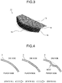
FIG. 3 is a perspective view of an example of a press-formed product formed by using a conventional tool of press forming. -
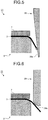
FIG. 4 is a drawing for explaining a deformation behavior exhibited at a tip end portion of a blank during a press forming process. -
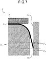
FIG. 5 is a cross-sectional view of an example of a tool of press forming in which a side wall forming portion of a die has a flat inclined surface according to the present invention. -
FIG. 6 is a drawing for explaining a conventional tool of press forming. -
FIG. 7 is a drawing for explaining a cross-sectional shape of a tool of press forming used by a press forming method according to the second embodiment of the present invention. -
FIG. 8 is a drawing for explaining a locus of the tip end of a blank during a press forming process according to the second embodiment of the present invention. -
FIG. 9 is a drawing for explaining a deformation of a blank and an inclination angle of a side wall forming portion of a die with respect to a horizontal direction according to the second embodiment of the present invention. -
FIG. 10 is a chart illustrating a locus of the tip end of a blank and an example of a calculation result of an optimal curve. -
FIG. 11 is a perspective view illustrating an example of a side wall forming portion of a die of a tool of press forming according to the second embodiment of the present invention. -
FIG. 12A is a drawing for explaining Example 1 of a tolerable cross-sectional shape of the side wall forming portion according to the second embodiment of the present invention. -
FIG. 12B is a drawing for explaining Example 2 of a tolerable cross-sectional shape of the side wall forming portion according to the second embodiment of the present invention. -
FIG. 12C is a drawing for explaining Example 3 of a tolerable cross-sectional shape of the side wall forming portion according to the second embodiment of the present invention. -
FIG. 13A is a drawing for explaining another example of a tolerable cross-sectional shape of the side wall forming portion according to the second embodiment of the present invention. -
FIG. 13B is a drawing for explaining an example of an intolerable cross-sectional shape of the side wall forming portion according to the second embodiment of the present invention. -
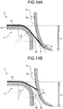
FIG. 14A is a drawing for explaining an example of the size of a blank according to the second embodiment of the present invention. -
FIG. 14B is a drawing for explaining another example of the size of a blank according to the second embodiment of the present invention. -
FIG. 15 is a drawing for explaining a press-formed product discussed in a first example and a third example. -
FIG. 16 is a drawing for explaining the shape of a blank used for forming a press-formed product discussed in a second example. - Exemplary embodiments of a press forming method and a tool of press forming of the present invention will be explained in detail below, with reference to the accompanying drawings. The present invention is not limited by these embodiments.
- In a press forming method according to a first embodiment of the present invention, as illustrated in
FIG. 2 , a press-formedproduct 11 having no flange portion is formed by performing a crash forming process while using a tool of press forming 1 illustrated inFIG. 1 . More specifically, as illustrated inFIG. 2 , the press-formedproduct 11 includes, at least, atop portion 13 and aside wall portion 15 that is continued from thetop portion 13 via a connectingportion 14. Either all or a part of theside wall portion 15 curves toward the outside to have a convex shape in a planar view. In the press forming method according to the first embodiment of the present invention, the press-formedproduct 11 illustrated inFIG. 2 is formed by performing a crash forming process, while using apunch 5, apad 7, and adie 9 included in the tool of press forming 1, as illustrated inFIG. 1 . According to this method, theside wall portion 15 of the press-formedproduct 11 is formed by constantly keeping a tip end portion of a blank 3 in contact with thedie 9 in such a manner that, in a sidewall forming portion 9a, thedie 9 imposes no restraint other than keeping the tip end portion in contact therewith. The reasons why the press forming method according to the first embodiment is able to prevent the occurrence of wrinkles in theside wall portion 15 will be explained in detail with reference toFIGS. 2 to 4 . - In a case where the press-formed
product 11 having theside wall portion 15 that curves toward the outside to have a convex shape in a planar view as illustrated inFIG. 2 is manufactured by performing a conventional crash forming process, when the height of theside wall portion 15 of the press-formedproduct 11 is equal to or greater than a certain level,wrinkles 19 occur (seeFIG. 3 ), because a shrink deformation is concentrated at a lower end of theside wall portion 15. It is considered that the wrinkles occur due to a mechanism which is explained below. - During the crash forming process to form the
side wall portion 15 curving toward the outside to have a convex shape in a planar view, when a deformation process is performed so as to shorten the linear length without buckling of the tip end portion of the blank 3 (seeFIG. 1 ) corresponding to the lower end of theside wall portion 15, the deformation at the tip end portion requires shrink deformation energy in an in-plane direction as well as deformation energy to increase the thickness. - However, when a deformation process is performed in an off-plane direction so as to cause the tip end portion of the blank 3 to buckle while the reduction of the linear length is inhibited, if the sum of the shrink deformation energy and the thickness increasing deformation energy in the in-plane direction and bending deformation energy in the off-plane direction is less than the sum of the shrink deformation energy and the thickness increasing deformation energy in the in-plane direction that do not cause the tip end portion to buckle, the tip end portion is deformed to buckle. As a result, the wrinkles occur toward the outside at the lower end of the
side wall portion 15. - To cope with this situation, when the press-formed
product 11 is formed so as to have a desired shape of the present invention, it is possible to prevent wrinkles from occurring on the outside, by arranging thedie 9 to press the tip end portion of the blank 3 so as not to spread outwardly, as illustrated inFIG. 1 . - In this situation, when the forming process is performed while the tip end portion of the blank 3 is pressed on the outside thereof, there is a possibility that the tip end portion may be bent toward the inside thereof.
FIG. 4 illustrates a horizontal cross-section (a cross-section of the blank 3 sectioned in a direction parallel to the plane of thetop portion 13 illustrated inFIG. 3 ) of the blank 3 used in the tip end portion of theside wall portion 15 of the press-formedproduct 11. In order for the tip end portion of the blank 3 in a state S1 illustrated inFIG. 4 to go into a state S3 illustrated inFIG. 4 during the forming step where the tip end portion of the blank 3 is deformed inwardly in terms of the off-plane direction by being bent inwardly, it would be necessary for the tip end portion to once go through a state S2 illustrated inFIG. 4 where the linear length is slightly shorter. However, from the aspect of deformation energy, a deformation to reach the state S2 illustrated inFIG. 4 where the tip end portion is bent inwardly so as to have a slightly shorter linear length has an extremely small possibility of occurring, compared to the shrink deformation in an in-plane direction. In other words, even when thedie 9 is arranged to press down the tip end portion of the blank 3 from the outside thereof, the possibility of the blank 3 being bent inwardly and having wrinkles is extremely small. - As explained above, by forming the tip end portion of the blank 3 by arranging the
die 9 to press down the tip end portion of the blank 3 from the outside thereof and to keep the tip end portion in contact therewith, while thedie 9 imposes no restraint other than keeping the tip end portion in contact therewith, it is possible to prevent the tip end portion from being deformed outwardly and to prevent the occurrence of wrinkles in the tip end portion. Further, the state where the wrinkles can easily occur toward the outside remains from a certain point in time during the forming process, up to the end of the forming process. It is therefore necessary to constantly keep the tip end portion of the blank 3 in contact with thedie 9, so as to press down the tip end portion from the outside thereof. - As an example of the forming method in which the tip end portion of the blank 3 is constantly kept in contact with the
die 9, there is a method in which, as described in a second embodiment later, the cross-sectional shape of the sidewall forming portion 9a of thedie 9 is devised. - The first embodiment presents the press forming method in which the crash forming process is performed while the top face of the blank 3 is being pressed by the
pad 7 as illustrated inFIG. 1 . It should be noted that, however, even when a forming process is performed without arranging thepad 7 to press the blank 3, it is possible to form theside wall portion 15 in such a manner that theside wall portion 15 of the press-formedproduct 11 has no wrinkles, as long as the tip end portion of the blank 3 is constantly kept in contact with the sidewall forming portion 9a of thedie 9 during the forming process in such a manner that no restraint is imposed on the tip end portion of the blank 3 other than keeping the tip end portion in contact. - It is sufficient when the tip end portion of the blank 3 kept in contact with the side
wall forming portion 9a of thedie 9 during the forming process corresponds to an extent from the tip end of the blank 3 defined by a distance up to four times longer than the thickness of the blank 3, as described in the first example below. When this condition is satisfied, it is possible to form theside wall portion 15 in such a manner that theside wall portion 15 has no wrinkles. - A tool of press forming 1 according to the second embodiment will be explained, with reference to
FIG. 1 illustrating a state during the forming process. The tool of press forming 1 according to the second embodiment of the present invention includes, at least, thetop portion 13 and theside wall portion 15 that is continued from thetop portion 13 via the connectingportion 14, as illustrated inFIG. 2 similar to the first embodiment explained above, so as to form the press-formedproduct 11 in which either all or a part of theside wall portion 15 curves toward the outside to have a convex shape in a planar view. As illustrated inFIG. 1 , the tool of press forming 1 includes: thepunch 5 that supports the lower face of the blank 3 that is tabular-shaped; thepad 7 that presses the top face of the blank 3 supported by a formingtop portion 5a of thepunch 5; and thedie 9 that performs a bending process while the sidewall forming portion 9a thereof abuts against the blank 3 held between thepunch 5 and thepad 7. - The
punch 5 includes: the formingtop portion 5a; apunch shoulder portion 5b that is a shoulder portion of the punch which continues downward at an angle from an end of the formingtop portion 5a; and a formingwall portion 5c that continues downward from a lower end side of thepunch shoulder portion 5b. The formingtop portion 5a supports the lower face of the blank 3, which is a flat face. Further, the cross-sectional shape of thepunch shoulder portion 5b is an arc having a radius curvature R. - The
pad 7 is arranged so as to oppose the formingtop portion 5a of thepunch 5 and is configured so as to be raised and lowered. By placing the blank 3 on the formingtop portion 5a of thepunch 5 and pressing the blank 3 by moving thepad 7 toward thepunch 5 side, it is possible to arrange the blank 3 to be held between thepunch 5 and thepad 7. - The
die 9 performs the bending deformation process on the blank 3 while abutting against the blank 3 and includes the sidewall forming portion 9a that forms theside wall portion 15 of the press-formedproduct 11. The cross-sectional shape of the sidewall forming portion 9a is curved as illustrated inFIG. 1 . Because the cross-sectional shape of the sidewall forming portion 9a is arranged to be curved, it is possible to constantly keep the tip end portion of the blank 3 in contact with the sidewall forming portion 9a during the forming process. Alternatively, as explained later, by using adie 39 that has a sidewall forming portion 39a of which the cross-sectional shape is a straight line as illustrated inFIG. 5 , it is also possible to constantly keep the tip end portion of the blank 3 in contact with the sidewall forming portion 39a during the forming process. - Next, a requirement for the cross-sectional shape of the side
wall forming portion 9a of thedie 9 to constantly keep the tip end portion of the blank 3 in contact with thedie 9 will be explained with reference toFIGS. 6 to 9 . InFIGS. 6 to 9 , some of the sections that are the same as, or that correspond to, those inFIG. 1 will be referred to by using the same reference signs. - When a press-formed product having a top portion, a side wall portion, and a flange portion is formed by performing a press forming process, while using a conventional tool of press forming 21 including the
punch 5, thepad 7, and a die 29 as illustrated inFIG. 6 , the cross-sectional shape of adie shoulder portion 29b is determined by the cross-sectional shape of a connecting portion connecting together the side wall portion and the flange portion of the press-formed product. - In contrast, when the press-formed
product 11 having no flange portion as targeted by the present invention is formed by performing a press forming process while using the conventional tool of press forming 21, it is possible for thedie shoulder portion 29b to have any cross-sectional shape regardless of the shape of the product resulting from the forming process of the press-formedproduct 11, except that the press-formedproduct 11 may have a forming defect such as a crack or wrinkles after the press forming process. - Thus, while a focus is placed on the aspect described above, an analysis was performed on the cross-sectional shape of the side
wall forming portion 9a to constantly keep the tip end of the blank 3 in contact with thedie 9 during the forming process. First, an analysis was performed on an example as illustrated inFIG. 7 in which the sidewall forming portion 9a of thedie 9 has an inclined surface of which the inclination angle is constant. - When the side
wall forming portion 9a of thedie 9 is structured to have the inclined surface of which the inclination angle is constant as illustrated inFIG. 7 , performing the forming process while constantly keeping the tip end of the blank 3 in contact with thedie 9 requires that an inclination angle θ2 of the inclined surface representing the sidewall forming portion 9a of thedie 9 with respect to the horizontal direction be equal to or greater than an inclination angle θ1, with respect to the horizontal direction, of the section positioned in the vicinity of the tip end of the blank 3 at the bottom dead point of the forming process, i.e., of theside wall portion 15 of the press-formedproduct 11. However, when the inclination angle θ2 of the inclined surface of which the inclination angle is constant as described above was determined to have a constant value that is equal to or greater than the inclination angle θ1 formed by the section positioned in the vicinity of the tip end of the blank 3 (seeFIG. 7 ), applying a bending deformation process to the blank 3 down to the bottom dead center of the forming process would require that the inclination angle θ2 of the inclined surface be close to 90 degrees because theside wall portion 15 is approximately perpendicular. It would therefore be necessary to determine the forming stroke of thedie 9 to be extremely long. - However, the inclination angle, with respect to the horizontal direction, of the tip end of the blank 3 corresponding to the
side wall portion 15 of the press-formedproduct 11 varies during the forming process. Thus, the inventors of the present application have discovered that it is possible to constantly keep the tip end of the blank 3 in contact with the sidewall forming portion 9a without the need to determine the forming stroke to be long, by arranging the cross-sectional shape of the sidewall forming portion 9a to be a cross-sectional shape expressed by a curve where the inclination angle of the sidewall forming portion 9a with respect to the horizontal direction changes in accordance with the position in which the tip end of the blank 3 is in contact with thedie 9 during the forming process. - The specific cross-sectional shape in which the inclination angle of the side
wall forming portion 9a with respect to the horizontal direction changes was determined in the following manner. As illustrated inFIG. 8 , the radius of the punch (hereinafter referred to as "punch radius") on a plane parallel to the horizontal direction of the formingtop portion 5a of thepunch 5 is expressed as "pr" [mm], while the radius curvature of thepunch shoulder portion 5b is expressed as "R" [mm], and the radius of the blank 3 (hereinafter referred to as "blank radius") on a plane parallel to the horizontal direction of the formingtop portion 5a is expressed as "br" [mm], whereas the thickness of the blank 3 is expressed as "t" [mm]. In that situation, a distance L from the point (the point A inFIG. 8 ) where the blank 3 becomes apart from thepunch shoulder portion 5b as a result of the bending deformation process performed thereon while the blank 3 abutting against thepunch shoulder portion 5b, to the tip end of the blank 3 can be expressed by using the formula presented below, where the contact angle "θ" [rad] of the blank 3 with respect to thepunch shoulder portion 5b is used as a parameter.
- Accordingly, it is possible to express a locus of the tip end position of the blank 3 during the forming process as a point (x, y) expressed by the following formula in an x-y coordinate system in which the origin O is the point serving as the center of the radius curvature of the curve in the horizontal direction on the forming
top portion 5a, while the x-axis corresponds to the horizontal direction of the formingtop portion 5a, whereas the y-axis corresponds to the vertical direction of the formingtop portion 5a.
- As illustrated in
FIG. 9 , the angle θB formed by the horizontal direction and the direction parallel to the section of the blank 3 at the tip end of the blank 3 kept in contact with the sidewall forming portion 9a is equal to the contact angle θ of the blank 3 with respect to thepunch shoulder portion 5b. Accordingly, in order for the sidewall forming portion 9a of thedie 9 to have a cross-sectional shape so as to be constantly kept in contact with the tip end of the blank 3, it is necessary that the inclination angle φ indicating the angle of the sidewall forming portion 9a with respect to the horizontal direction at the point (the point B inFIG. 9 ) where the tip end of the blank 3 is kept in contact be equal to or greater than the angle θB at all times. It is therefore necessary that the contact angle θ of the blank 3 with respect to thepunch shoulder portion 5b and the inclination angle φ satisfy the relationship expressed in Expression (1) presented below:
- Accordingly, when the user wishes to keep the height of the side
wall forming portion 9a, i.e., the forming stroke as short as possible, the inclination angle φ should be the smallest, i.e., the condition θ = φ should be satisfied. - Consequently, in an X-Y coordinate system in which the origin O is the point serving as the center of the radius curvature of the aforementioned curve in the horizontal direction on the forming
top portion 5a of thepunch 5, while the X-axis corresponds to the horizontal direction of the formingtop portion 5a, whereas the Y-axis corresponds to the vertical direction of the formingtop portion 5a, when the coordinates of the surface of the sidewall forming portion 9a are expressed as "(X, Y)", the Y component decreases when the inclination angle φ becomes equal to the contact angle θ as the X component increases, with respect to the coordinates (X, Y) indicating the surface of the sidewall forming portion 9a. Consequently, it is possible to determine an optimal cross-sectional shape of the sidewall forming portion 9a by satisfying the relationship expressed in the formula presented below.
- Consequently, it is possible to express the optimal cross-sectional shape of the side
wall forming portion 9a in the X-Y coordinate system described above, by using an optimal curve drawn by the formula presented below.
- By simplifying the above formula, it is possible to express the optimal curve indicating the optimal cross-sectional shape of the side
wall forming portion 9a by using Expression (2) presented below.
-
FIG. 10 illustrates, as an example, a locus of the tip end of the blank 3 and an optimal curve obtained by calculating numerical values of the contact angle θ [rad] in the range of 0 ≤ θ ≤ π/2 with increments of π/180, while the punch radius satisfies pr = 80 [mm], the radius curvature of thepunch shoulder portion 5b satisfies R = 5 [mm], the blank radius satisfies br = 100 [mm], and the thickness of the blank 3 satisfies t = 1.2 [mm]. - As explained above, by calculating the optimal curve while giving values to the parameters presented in Expression (2), it is possible to determine the optimal cross-sectional shape of the side
wall forming portion 9a. By arranging the sidewall forming portion 9a to have the optimal cross-sectional shape, it is possible to prevent the forming stroke from increasing, while constantly having the tip end of the blank 3 abut against the sidewall forming portion 9a.FIG. 11 illustrates an example of the sidewall forming portion 9a having the optimal cross-sectional shape determined by using the method described above. - Further, when the inclination angle of the tangential line of the optimal curve with respect to the horizontal direction in an arbitrary X-coordinate position within in the X-Y coordinate system described above is referred to as an "optimal inclination angle", the condition defined in Expression (1) is satisfied at all times during the forming process, as long as the cross-sectional shape of the side
wall forming portion 9a is such a cross-sectional shape (hereinafter referred to as a "tolerable cross-sectional shape") that is expressed with a curve where the inclination angle of the tangential line at the arbitrary X-coordinate position with respect to the horizontal line is equal to or greater than the optimal inclination angle. Consequently, during the forming process, the bending deformation process is performed while the tip end of the blank 3 is constantly kept in contact with the sidewall forming portion 9a. It is therefore possible to prevent the occurrence of wrinkles in the side wall portion of the press-formed product. -
FIGS. 12-A to 12-C are drawings that illustrate examples of tolerable cross-sectional shapes of the sidewall forming portion 9a that satisfy Expression (1). It is assumed that the tip end of the blank 3 is, without fail, in contact with the sidewall forming portion 9a at the start of the press forming process. -
FIG. 12A illustrates Example 1 of the tolerable cross-sectional shape of the sidewall forming portion 9a. The tolerable cross-sectional shape in Example 1 is a tolerable cross-sectional shape expressed with an inclined surface of which the inclination angle φ2 is constant. In Example 1, as illustrated inFIG. 12A , the inclination angle φ2 is greater than the optimal inclination angle φ1.FIG. 12B illustrates Example 2 of the tolerable cross-sectional shape of the sidewall forming portion 9a. The tolerable cross-sectional shape in Example 2 is a tolerable cross-sectional shape obtained by applying analogous enlargement to the optimal cross-sectional shape. As illustrated inFIG. 12B , in an arbitrary X-coordinate position, the inclination angle φ2 of the tangential line of the curve expressing the tolerable cross-sectional shape in Example 2 with respect to the horizontal direction is greater than the optimal inclination angle φ1.FIG. 12C illustrates Example 3 of the tolerable cross-sectional shape of the sidewall forming portion 9a. The tolerable cross-sectional shape in Example 3 is a tolerable cross-sectional shape expressed with an arc having a large radius curvature. In Example 3, as illustrated inFIG. 12C , the inclination angle φ2 of the tangential line of the arc at an arbitrary X-coordinate position is greater than the optimal inclination angle φ1. - Consequently, the cross-sectional shape of the side
wall forming portion 9a satisfies the condition defined in Expression (1) in any of the examples illustrated inFIGS. 12A to 12C . It is therefore possible to perform the bending deformation process while constantly keeping the tip end of the blank 3 in contact with the sidewall forming portion 9a. - Alternatively, as long as the condition defined in Expression (1) is satisfied at an arbitrary X-coordinate position, the cross-sectional shape of the side
wall forming portion 9a may be a tolerable cross-sectional shape that is expressed, as illustrated inFIG. 13A , with a curve where the inclination angle φ2 (not illustrated inFIG. 13A ) of the tangential line at the arbitrary X-coordinate position with respect to the horizontal direction decreases in an intermediate section. - However, when the cross-sectional shape of the side
wall forming portion 9a is a cross-sectional shape that is expressed, as illustrated inFIG. 13B for example, with a curve where the inclination angle φ2 of the tangential line at a certain X-coordinate position XA is less than the optimal inclination angle φ1, the condition defined in Expression (1) is not satisfied. Such cross-sectional shapes that do not satisfy the condition defined in Expression (1) are intolerable cross-sectional shapes that are not tolerable for the sidewall forming portion 9a. When the cross-sectional shape of the sidewall forming portion 9a is an intolerable cross-sectional shape, a section other than the tip end of the blank 3 comes into contact with the sidewall forming portion 9a. Thus, it is not desirable when the sidewall forming portion 9a has a cross-sectional shape such as that illustrated inFIG. 13B . It should be noted that, however, when the cross-sectional shape of the sidewall forming portion 9a is such a shape that the extent from the tip end of the blank 3 defined by a distance up to four times longer than the thickness of the blank 3 is constantly kept in contact with the sidewall forming portion 9a during the side wall forming process, it is possible to prevent the occurrence of wrinkles. - Also, by applying the tool of press forming 1 of the present invention to a forming process performed on a blank having a smaller radius (hereinafter referred to as a "smaller blank 43") than the blank radius br of the blank (hereinafter referred to as a "basic blank 41") used for calculating the optimal cross-sectional shape of the side
wall forming portion 9a, it is also possible to prevent the occurrence of wrinkles. This aspect will be explained below, with reference toFIGS. 14A and 14B . - As illustrated in
FIG. 14A , during the forming process performed on the basic blank 41 while using the tool of press forming 1, the contact angle of the basic blank 41 with respect to thepunch shoulder portion 5b is expressed as "θ", when the moving distance of thedie 9 is expressed as "Ls", while using the height of the formingtop portion 5a of thepunch 5 as a reference. Further, the inclination angle of the tangential line of thedie 9 with respect to the horizontal direction at the point (the point A inFIG. 14A ) where the tip end of the basic blank 41 is in contact with the sidewall forming portion 9a is expressed as "φ1". Similarly, as illustrated inFIG. 14B , during the forming process performed on the smaller blank 43 while using the tool of press forming 1, the contact angle of the smaller blank 43 with respect to thepunch shoulder portion 5b is expressed as "θ'", when the moving distance of thedie 9 toward thepunch 5 side is expressed as "Ls". Further, the inclination angle of the tangential line of thedie 9 with respect to the horizontal direction at the point (the point B inFIG. 14B ) where the tip end of the smaller blank 43 is in contact with the sidewall forming portion 9a is expressed as "φ2". - As illustrated in
FIGS. 14A and 14B , the contact angle θ' of the smaller blank 43 is less than the contact angle θ of the basic blank 41 at all times, regardless of the value of the moving distance Ls of thedie 9. Further, the inclination angle φ2 of the tangential line of thedie 9 at the point where the tip end of the smaller blank 43 is in contact with the sidewall forming portion 9a is greater than the contact angle θ'. Accordingly, when a forming process is performed on the smaller blank 43 by using thedie 9 having the sidewall forming portion 9a of which the cross-sectional shape is determined on the basis of the basic blank 41, the relationship defined in Expression (1) is always satisfied. Consequently, because the forming process is performed while the tip end of the smaller blank 43 is constantly kept in contact with the sidewall forming portion 9a, it is possible to prevent the occurrence of wrinkles. It should be noted that, however, for the purpose of keeping the smaller blank 43 in contact with thedie 9 from the start of the press forming process, it is necessary that the radius of the smaller blank 43 is greater than the punch radius. - In this situation, the section in which the cross-sectional shape of the side
wall forming portion 9a of thedie 9 is determined in the manner described above may be applied to only a target section for which the occurrence of wrinkles is to be prevented in theside wall portion 15 of the press-formedproduct 11. Alternatively, the cross-section determination process may be whole of theside wall portion 15. - Further, even when the radius curvature of the
side wall portion 15 curving toward the outside to have a convex shape in a planar view is not constant throughout the whole of theside wall portion 15, it may be a good idea to design thedie 9, by dividing theside wall portion 15 into sections in each of which the radius curvature of the curve is the same, determining a cross-sectional shape of the sidewall forming portion 9a of thedie 9 for each of the divided sections by using the method described above, and joining together the cross-sectional shapes determined for the divided sections to form the sidewall forming portion 9a. - An experiment was conducted to verify that it is possible to prevent the occurrence of wrinkles in the side wall portion curving toward the outside of the press-formed product to have a convex shape in a planar view, by using the press forming method and the tool of press forming according to the present invention so as to form the side wall portion of the press-formed product by constantly keeping the tip end portion of the blank corresponding to an extent from the tip end of the blank defined by a distance up to four times longer than the thickness of the blank in contact with the side wall forming portion of the die, while no restraint was imposed on the tip end portion of the blank other than keeping the tip end portion in contact. The experiment will be explained below.
- A first example corresponds to a situation where a crash forming process is performed to form a press-formed
product 51 that has aside wall portion 55 continued from a disc-shapedtop portion 53 via a connectingportion 54 illustrated inFIG. 15 . As for the dimension of the press-formedproduct 51, the radius r of thetop portion 53 was 90 [mm], while the radius curvature of the connectingportion 54 was 8 [mm]. Further, two types ofblanks 3 were used for forming the press-formedproduct 51, namely, a steel sheet A that had a thickness t of 1.2 [mm] and had a tensile strength of 590 [MPa] grade; and a steel sheet B that had a thickness t of 1.6 [mm] and had a tensile strength of 590 [MPa] grade. Further, to form the press-formedproduct 51 having the disc-shapedtop portion 53, the blank 3 had a disc shape of which the radius (the blank radius) was 105 [mm] for the steel sheet A and was 107 [mm] for the steel sheet B. - To press-form the press-formed
product 51 by performing the crash forming process on theblanks 3 having the above specifications, while using the tool of press forming 1 according to the present invention of which the cross-section is illustrated inFIG. 1 , the punch radius of thepunch 5 was 90 [mm], while the radius curvature of thepunch shoulder portion 5b was 8 [mm]. The sidewall forming portion 9a of thedie 9 had a cross-sectional shape determined for every millimeter in the range of br = 100 [mm] to 105 [mm], while the parameters in the Expression (2) were determined to satisfy pr = 90 [mm], R = 8 [mm], and t = 1.2 [mm]. - Because the blank radius of the blank 3 used for the press forming process is 105 [mm], when the side
wall forming portion 9a has an optimal cross-sectional shape calculated by arranging the blank radius of the blank 3 in Expression (2) to satisfy br = 105 [mm], the forming process is performed while only the tip end of the blank 3 is in contact with the sidewall forming portion 9a. In contrast, when the sidewall forming portion 9a has a cross-sectional shape determined by using another value br less than the blank radius of the blank 3, the forming process is performed while a tip end portion including a section positioned on the inside of the tip end of the blank 3 is in contact with the sidewall forming portion 9a. In this situation, the greater the difference is between the blank radius of the blank 3 and the value of br in Expression (2), the greater the extent of the tip end portion that is in contact with the sidewall forming portion 9a becomes. - Table 1 illustrates results regarding whether wrinkles occurred or not in the
side wall portions 55 of the press-formedproducts 51 and the extent (the distance) "a" of the tip end portion of the blank 3 that was in contact with the sidewall forming portion 9a, when the crash forming process was performed on the steel sheet A and the steel sheet B under the abovementioned conditions.Table 1 Steel Sheet A (590 MPa-grade, Thickness 1.2 mm, Blank radius 105 mm) br [mm] Extent a [mm] of tip end portion of blank that is in contact with side wall forming portion a/t [-] Occurrence of Wrinkles 105 0.0 0.0 No 104 1.2 1.0 No 103 2.4 2.0 No 102 3.6 3.0 No 101 4.8 4.0 No 100.5 5.4 4.5 Yes Steel Sheet B (590 MPa-grade, Thickness 1.6 mm, Blank radius 107 mm) br [mm] Extent a [mm] of tip end portion of blank that is in contact with side wall forming portion a/t [-] Occurrence of Wrinkles 107 0.0 0.0 No 106 1.6 1.0 No 105 3.2 2.0 No 104 4.8 3.0 No 103 6.4 4.0 No 102 8.0 5.0 Yes - As indicated in Table 1, it was verified that an advantageous effect of preventing the occurrence of wrinkles in the press-formed
products 51 was achieved, with respect to both the steel sheet A and the steel sheet B, when the ratio between the extent (the distance) "a" of the tip end portion and the thickness t of the blank 3 was equal to or less than 4.0 times, because the tip end portion of the blank 3 was pressed down from the outside while being constantly kept in contact with the sidewall forming portion 9a of thedie 9. In other words, by determining the cross-sectional shape of the sidewall forming portion 9a on the basis of Expression (2) in such a manner that the tip end portion of the blank 3 corresponding to an extent from the tip end of the blank 3 defined by a distance up to four times longer than the thickness is kept in contact with the sidewall forming portion 9a of thedie 9, it is possible to prevent the occurrence of wrinkles in theside wall portion 55, when the press-formedproduct 51 shaped to curve outward to have a convex shape is formed by performing the crash forming process. - In a second example, it was checked to see whether wrinkles occurred or not in the
side wall portion 15, when the press-formedproduct 11 having theside wall portion 15 curving toward the outside to have a convex shape in a planar view as illustrated inFIG. 2 was formed by performing a crash forming process while using the tool of press forming 1 according to the present invention as illustrated inFIG. 1 . - As for the dimension of the press-formed
product 11, the radius curvature of the cross-sectional plane of the connectingportion 14 connecting together thetop portion 13 and theside wall portion 15 was 5 [mm], while the radius curvature of the curve on a plane parallel to the horizontal direction of thetop portion 13 was 80 [mm]. The blank 3 was a steel sheet that had a thickness of 1.2 [mm] and a tensile strength of 980 [MPa] grade. An optimal cross-sectional shape A of the sidewall forming portion 9a of thedie 9 was determined on the basis of the dimensions in the press-formedproduct 11, while the parameters in Expression (2) were determined to satisfy pr = 80 [mm], R = 5 [mm], t = 1.2 [mm], and br = 100 [mm]. As explained in the second embodiment, the blank 3 having such a blank radius that is less than br = 100 [mm] and is greater than the punch radius pr of thepunch 5 falls within the scope of the present invention. The blank radius of the blank 3 denotes, as illustrated inFIG. 16 , the radius curvature of the curve at the tip end portion of the blank 3. - The second example corresponds to situations where, in addition to the tool of press forming 1 (Example 1 of the present invention) including the
die 9 having the sidewall forming portion 9a with the optimal cross-sectional shape A described above, a tool of press forming 31 (Example 2 of the present invention) including the die 39 having the sidewall forming portion 39a of which the inclination angle with respect to the horizontal direction was constant as illustrated inFIG. 5 , and a tool of press forming 21 (Comparative Example 1) including the die 29 having a conventional shape and having adie shoulder portion 29b of which the radius curvature was constant (= 5 [mm]) as illustrated inFIG. 6 were used to perform a crash forming process onblanks 3 having mutually-different blank radius values. In the second example, it was checked to see whether wrinkles occurred or not by varying the press-formed-product height h of the press-formedproduct 11 in each of these situations. The inclination angle of the sidewall forming portion 39a with respect to the horizontal direction in Example 2 of the present invention was a maximum inclination angle (= 87.7 [°]) calculated from the inclination angle of theside wall portion 15 of the press-formedproduct 11 with respect to the horizontal direction. Results from the second example are presented in Table 2.
- As indicated in Table 2, in Example 1 of the present invention and Example 2 of the present invention, no wrinkles occurred in the
side wall portion 15 of the press-formedproduct 11, regardless of the values of the blank radius. In particular, even when the blank radius was 100 [mm], it was possible to form theside wall portion 15 without any wrinkles. As understood from Table 2, the results from Example 1 of the present invention and Example 2 of the present invention were better than those from Comparative Example 1 formed by using the conventional tool of press forming 21. - Further, the forming stroke in Example 1 of the present invention was 80 [mm], whereas the forming stroke in Example 2 of the present invention was 470 [mm]. It was therefore possible to prevent the forming stroke from increasing, by arranging the side
wall forming portion 9a of thedie 9 to have the optimal cross-sectional shape A. - As explained above, it was verified that, by determining the side wall forming portion of the die to have such a cross-sectional shape that constantly keeps the tip end portion of the blank in contact wherewith, it was possible to prevent the occurrence of wrinkles in the
side wall portion 15 of the press-formedproduct 11, even when the press-formed-product height h was high. Further, it was indicated that, by arranging the side wall forming portion of the die to have the optimal cross-sectional shape, it was possible to form theside wall portion 15 of the press-formedproduct 11 without significantly increasing the forming stroke. - In a third example, it was checked to see whether wrinkles occurred or not in the
side wall portion 55 of the press-formedproduct 51, when the disc-shaped press-formedproduct 51 illustrated inFIG. 15 was formed by performing a crash forming process while using the tool of press forming 1 according to the present invention. - As illustrated in
FIG. 15 , the press-formedproduct 51 has thetop portion 53 and theside wall portion 55. Thetop portion 53 and theside wall portion 55 are connected together in continuity by the connectingportion 54 represented by an arc-shaped curved plane having a constant curvature. The height of theside wall portion 55 corresponds to the height of the press-formed product 51 (i.e., the press-formed-product height h). In the third example, the press-formedproduct 51 was formed by using a steel sheet serving as the blank 3 that had a thickness of 1.2 mm and a tensile strength of 590 [MPa] grade, while using the tool of press forming 1 of which the cross-section is illustrated inFIG. 1 . As for the dimension of the press-formedproduct 51, the radius r of thetop portion 53 was 90 [mm], whereas the radius curvature of the connectingportion 54 connecting together thetop portion 53 and theside wall portion 55 was 8 [mm]. - In the third example, an optimal cross-sectional shape of the side
wall forming portion 9a of thedie 9 was determined on the basis of the dimensions of the press-formedproduct 51 described above, while the parameters in Expression (2) were determined to satisfy pr = 80 [mm], R = 5 [mm], and t = 1.2 [mm]. In that situation, two types of optimal cross-sectional shapes of the sidewall forming portion 9a were used, namely, an optimal cross-sectional shape B (Example 3 of the present invention) corresponding to br = 110 [mm] and an optimal cross-sectional shape C (Example 4 of the present invention) corresponding to br = 105 [mm]. In the third example, an analysis was performed on these two types of sidewall forming portions 9a. Further, the third example corresponds to situations where advantageous effects of the present invention were verified by making comparisons with crash forming processes performed by using the conventional tool of press forming 21 as illustrated inFIG. 6 . Two types of the conventional tool of press forming 21 were used, namely, one in which thedie shoulder portion 29b had a radius curvature of 8 [mm] (Comparative Example 2) and the other in which thedie shoulder portion 29b had a radius curvature of 2 [mm] - The third example corresponds to situations where a crash forming process was performed on each of the
blanks 3 having mutually-different radius values, while using either the tool of press forming 1 (either Example 3 or Example 4 of the present invention) of which the sidewall forming portion 9a had the optimal cross-sectional shape or the conventional tool of press forming 21 (either Comparative Example 2 or Comparative Example 3). In the third example, it was checked to see whether wrinkles occurred or not in theside wall portion 55 of each of the obtained press-formedproducts 51. Results from the third example are presented in Table 3.

- As indicated in Table 3, compared to Comparative Example 3 in which the radius curvature of the
die shoulder portion 29b was 2 [mm], Comparative Example 2 having a greater radius curvature exhibited a slightly better wrinkle prevention effect. However, by using the tool of press forming 1 including the sidewall forming portion 9a that had either the optimal cross-sectional shape B or the optimal cross-sectional shape C presented as Examples 3 and 4 of the present invention, it was possible to press-form theside wall portion 55 of the press-formedproduct 51 without any wrinkles, with even greater blank radius values. - As explained above, it was verified that, by using the tool of press forming according to the present invention, it is possible to significantly improve the wrinkle prevention effect, compared to situations using the conventional tool of press forming.
- As explained above, the press forming method and the tool of press forming according to the present invention are useful in the crash forming processes of the press-formed products. In particular, the press forming method and the tool of press forming are suitable as a press forming method and a tool of press forming used for easily forming, in a single step, the side wall portion curving toward the outside of the press-formed product to have a convex shape in a planar view, while preventing the occurrence of wrinkles.
-
- 1
- TOOL OF PRESS FORMING
- 3
- BLANK
- 5
- PUNCH
- 5a
- FORMING TOP PORTION
- 5b
- PUNCH SHOULDER PORTION
- 5c
- FORMING WALL PORTION
- 7
- PAD
- 9
- DIE
- 9a
- SIDE WALL FORMING PORTION
- 11
- PRESS-FORMED PRODUCT
- 13
- TOP PORTION
- 14
- CONNECTING PORTION
- 15
- SIDE WALL PORTION
- 19
- WRINKLES
- 21
- (CONVENTIONAL) TOOL OF PRESS FORMING
- 29
- (CONVENTIONAL) DIE
- 29b
- (CONVENTIONAL) DIE SHOULDER PORTION
- 31
- TOOL OF PRESS FORMING
- 39
- DIE
- 39a
- SIDE WALL FORMING PORTION
- 41
- BASIC BLANK
- 43
- SMALLER BLANK
- 51
- PRESS-FORMED PRODUCT
- 53
- TOP PORTION
- 54
- CONNECTING PORTION
- 55
- SIDE WALL PORTION
Claims (2)
- A press forming method for forming a press-formed product (11) having no flange portion from a blank by performing a crash forming process while using a die (9) and a punch (5), wherein the punch has a forming top portion (5a) on which a blank (3) is placed, a punch shoulder portion (5b) that is continued from the forming top portion and extends along the curving of the press-formed product, and a forming wall portion (5c) continued from the punch shoulder portion; and
the die has a side wall forming portion (9a) that forms the side wall portion (15) of the press-formed product (11) by moving relative to the punch, wherein
in an X-Y coordinate system in which an origin (O) is a point serving as a center of a radius curvature of the curving on the forming top portion, while an X-axis corresponds to a horizontal direction, whereas a Y-axis corresponds to a vertical direction, a curve drawn by a formula presented below is referred to as an optimal curve, while an inclination angle of a tangential line of the optimal curve at an arbitrary X-coordinate position is referred to as an optimal inclination angle,
the side wall forming portion (9a) of the die (9) has a cross-sectional shape expressed with a curve where an inclination angle of a tangential line at the arbitrary X-coordinate position with respect to the horizontal direction is equal to or greater than the optimal inclination angle. where pr : a radius [mm] of the punch;R : a radius curvature [mm] of the punch shoulder portion;br : a radius [mm] of the blank;t : a thickness [mm] of the blank; andθ : a contact angle (0 ≤ θ ≤ π/2) [rad] of the blankwith respect to the punch shoulder portion.
the press-formed product (11) including at least a top portion (13) and a side wall portion (15) continued from the top portion via a connecting portion (14) and being structured so that either all or a part of the side wall portion curves toward an outside of the press-formed product to form a convex shape in a planar view, the press forming method comprising:
forming the side wall portion while keeping a tip end portion of the blank in continuous contact with a side wall forming portion of the die and causing the die to impose restraint only on the tip end portion of the blank, wherein the tip end portion of the blank corresponds to an extent from a tip end of the blank defined by a distance up to four times longer than a thickness of the blank. - A tool of press forming for forming a press-formed product (11) having no flange portion by performing a crash forming process, the press-formed product including at least a top portion (13) and a side wall portion (15) continued from the top portion via a connecting portion (14) and being structured so that either all or a part of the side wall portion curves toward an outside of the press-formed product to form a convex shape in a planar view, the tool of press forming comprising:a punch (5) that has a forming top portion (5a) on which a blank (3) is placed, a punch shoulder portion (5b) that is continued from the forming top portion and extends along the curving of the press-formed product, and a forming wall portion (5c) continued from the punch shoulder portion; anda die (9) that has a side wall forming portion (9a) that forms the side wall portion (15) of the press-formed product (11) by moving relative to the punch, the tool being characterized in thatin an X-Y coordinate system in which an origin (O) is a point serving as a center of a radius curvature of the curving on the forming top portion, while an X-axis corresponds to a horizontal direction, whereas a Y-axis corresponds to a vertical direction, a curve drawn by a formula presented below is referred to as an optimal curve, while an inclination angle of a tangential line of the optimal curve at an arbitrary X-coordinate position is referred to as an optimal inclination angle,the side wall forming portion of the die has a cross-sectional shape expressed with a curve where an inclination angle of a tangential line at the arbitrary X-coordinate position with respect to the horizontal direction is equal to or greater than the optimal inclination angle.with respect to the punch shoulder portion.
 where pr : a radius [mm] of the punch;R : a radius curvature [mm] of the punch shoulder portion;br : a radius [mm] of the blank;t : a thickness [mm] of the blank; andθ : a contact angle (0 ≤ θ ≤ π/2) [rad] of the blank
Applications Claiming Priority (2)
| Application Number | Priority Date | Filing Date | Title |
|---|---|---|---|
| JP2015054952A JP5987942B1 (en) | 2015-03-18 | 2015-03-18 | Press mold |
| PCT/JP2016/052300 WO2016147703A1 (en) | 2015-03-18 | 2016-01-27 | Press-forming method and press-forming tool |
Publications (3)
| Publication Number | Publication Date |
|---|---|
| EP3272437A1 EP3272437A1 (en) | 2018-01-24 |
| EP3272437A4 EP3272437A4 (en) | 2018-11-21 |
| EP3272437B1 true EP3272437B1 (en) | 2019-11-13 |
Family
ID=56871777
Family Applications (1)
| Application Number | Title | Priority Date | Filing Date |
|---|---|---|---|
| EP16764534.0A Active EP3272437B1 (en) | 2015-03-18 | 2016-01-27 | Press-forming method and press-forming tool |
Country Status (7)
| Country | Link |
|---|---|
| US (1) | US10500624B2 (en) |
| EP (1) | EP3272437B1 (en) |
| JP (1) | JP5987942B1 (en) |
| KR (1) | KR102001328B1 (en) |
| CN (1) | CN107427884B (en) |
| MX (1) | MX2017011881A (en) |
| WO (1) | WO2016147703A1 (en) |
Families Citing this family (5)
| Publication number | Priority date | Publication date | Assignee | Title |
|---|---|---|---|---|
| CA3011213C (en) * | 2016-01-26 | 2020-05-12 | Nippon Steel & Sumitomo Metal Corporation | A pressing machine and a method for manufacturing a press-formed product |
| JP6590129B1 (en) * | 2018-02-28 | 2019-10-16 | Jfeスチール株式会社 | Metal plate for press forming, press forming apparatus, and manufacturing method of press part |
| JP6919690B2 (en) * | 2018-12-06 | 2021-08-18 | Jfeスチール株式会社 | Manufacturing method of pressed parts and design method of lower die |
| CN115214782B (en) * | 2021-04-16 | 2023-08-15 | 广州汽车集团股份有限公司 | Side wall A post end structure |
| CN113319172B (en) * | 2021-05-11 | 2022-10-28 | 中国第一汽车股份有限公司 | Method for eliminating bending of flanging vertical wall of high Jiang Ban stamping part |
Family Cites Families (16)
| Publication number | Priority date | Publication date | Assignee | Title |
|---|---|---|---|---|
| US2321344A (en) * | 1939-03-04 | 1943-06-08 | Remington Arms Co Inc | Projectile |
| JPS5217363A (en) * | 1975-06-25 | 1977-02-09 | Ishizuka Seiki Kk | Method of making metallic drive plugs |
| JPH0647135B2 (en) | 1988-03-11 | 1994-06-22 | 日新製鋼株式会社 | Method for manufacturing metal products having arcuate portions at corners |
| JP2663701B2 (en) * | 1990-10-12 | 1997-10-15 | 日産自動車株式会社 | Press mold |
| JPH0647135A (en) | 1992-07-30 | 1994-02-22 | Sophia Co Ltd | Game machine |
| JP2003120463A (en) * | 2001-10-16 | 2003-04-23 | Hitachi Ltd | Manufacturing method of fuel injection valve, nozzle body, and cylindrical parts having fluid passage |
| JP2005095937A (en) * | 2003-09-25 | 2005-04-14 | Toyota Auto Body Co Ltd | Press die and pressing method |
| JP2005254279A (en) | 2004-03-11 | 2005-09-22 | Toyota Auto Body Co Ltd | Press die |
| JP2008200709A (en) | 2007-02-20 | 2008-09-04 | Nissan Motor Co Ltd | Apparatus and method for manufacturing press-formed product and press formed product |
| DE102008034996B4 (en) * | 2008-07-25 | 2010-11-18 | Benteler Automobiltechnik Gmbh | Apparatus for thermoforming, press hardening and cutting of a semifinished product of hardenable steel |
| JP5199805B2 (en) * | 2008-09-24 | 2013-05-15 | 東プレ株式会社 | Die quench processed product, manufacturing method and manufacturing apparatus thereof |
| EP2644293B1 (en) | 2010-11-24 | 2016-07-27 | Nippon Steel & Sumitomo Metal Corporation | Method for manufacturing l-shaped product |
| JP5808297B2 (en) * | 2012-06-27 | 2015-11-10 | Jfeスチール株式会社 | Press forming method, press forming apparatus |
| US9452461B2 (en) | 2013-01-09 | 2016-09-27 | Nippon Steel & Sumitomo Metal Corporation | Press forming method |
| JP5569609B1 (en) * | 2013-02-28 | 2014-08-13 | Jfeスチール株式会社 | Press forming method |
| JP5664810B1 (en) * | 2013-06-27 | 2015-02-04 | Jfeスチール株式会社 | Press forming method and apparatus |
-
2015
- 2015-03-18 JP JP2015054952A patent/JP5987942B1/en active Active
-
2016
- 2016-01-27 US US15/552,615 patent/US10500624B2/en active Active
- 2016-01-27 WO PCT/JP2016/052300 patent/WO2016147703A1/en active Application Filing
- 2016-01-27 CN CN201680015831.3A patent/CN107427884B/en active Active
- 2016-01-27 EP EP16764534.0A patent/EP3272437B1/en active Active
- 2016-01-27 KR KR1020177025627A patent/KR102001328B1/en active IP Right Grant
- 2016-01-27 MX MX2017011881A patent/MX2017011881A/en unknown
Non-Patent Citations (1)
| Title |
|---|
| None * |
Also Published As
| Publication number | Publication date |
|---|---|
| EP3272437A1 (en) | 2018-01-24 |
| CN107427884A (en) | 2017-12-01 |
| CN107427884B (en) | 2019-09-03 |
| US10500624B2 (en) | 2019-12-10 |
| MX2017011881A (en) | 2018-06-07 |
| US20180021831A1 (en) | 2018-01-25 |
| JP5987942B1 (en) | 2016-09-07 |
| EP3272437A4 (en) | 2018-11-21 |
| KR102001328B1 (en) | 2019-07-17 |
| KR20170117495A (en) | 2017-10-23 |
| JP2016175087A (en) | 2016-10-06 |
| WO2016147703A1 (en) | 2016-09-22 |
Similar Documents
| Publication | Publication Date | Title |
|---|---|---|
| EP3272437B1 (en) | Press-forming method and press-forming tool | |
| EP3272438B1 (en) | Method for producing press-molded product, press-molded product, and pressing device | |
| EP2878392B1 (en) | Press-forming mold and method for manufacturing press-formed product | |
| KR101853573B1 (en) | Press forming method, method for manufacturing press-formed component and method for determining preform shape used in these methods | |
| JP6418249B2 (en) | Blank, molded product manufacturing method, mold and blank manufacturing method | |
| CN107921504B (en) | Method for manufacturing stretch flange formed part | |
| JP2006289480A (en) | Press forming method and metal mold used for the same | |
| CN110087791B (en) | Press forming method | |
| EP3441153B1 (en) | Method for producing press-molded article and production line thereof | |
| US10413956B2 (en) | Press forming method and method of manufacturing press formed product | |
| CN112512716B (en) | Stretch flange forming tool, stretch flange forming method using same, and stretch flange-equipped member | |
| WO2016194503A1 (en) | Press forming method and tool of press forming | |
| JP6729841B1 (en) | Press molding method and press machine | |
| EP3778053A1 (en) | Designing method for press-molded article, press-molding die, press-molded article, and production method for press-molded article | |
| JP6319383B2 (en) | Manufacturing method of stretch flange molded parts | |
| US20230057735A1 (en) | Manufacturing method of press formed product, press forming apparatus, and press forming line | |
| JP7070287B2 (en) | Manufacturing method of press-molded parts and press-molded parts | |
| JP6319382B2 (en) | Manufacturing method of stretch flange molded parts | |
| KR20170081215A (en) | Press-forming method and method of manufacturing component employing same method, and press-forming device and formed component press-formed using same device | |
| JP2021159951A (en) | Method for manufacturing sheet-metal-formed product, device for manufacturing sheet-metal-formed product, and tool for flange-up | |
| US20190168822A1 (en) | Structural member and method of production of same | |
| US20230191469A1 (en) | Press forming method | |
| US20230182189A1 (en) | Press forming tool and press forming method | |
| US20230173566A1 (en) | Press forming method | |
| US20230201903A1 (en) | Press forming tool and press forming method |
Legal Events
| Date | Code | Title | Description |
|---|---|---|---|
| STAA | Information on the status of an ep patent application or granted ep patent |
Free format text: STATUS: THE INTERNATIONAL PUBLICATION HAS BEEN MADE |
|
| PUAI | Public reference made under article 153(3) epc to a published international application that has entered the european phase |
Free format text: ORIGINAL CODE: 0009012 |
|
| STAA | Information on the status of an ep patent application or granted ep patent |
Free format text: STATUS: REQUEST FOR EXAMINATION WAS MADE |
|
| 17P | Request for examination filed |
Effective date: 20170908 |
|
| AK | Designated contracting states |
Kind code of ref document: A1 Designated state(s): AL AT BE BG CH CY CZ DE DK EE ES FI FR GB GR HR HU IE IS IT LI LT LU LV MC MK MT NL NO PL PT RO RS SE SI SK SM TR |
|
| AX | Request for extension of the european patent |
Extension state: BA ME |
|
| DAV | Request for validation of the european patent (deleted) | ||
| DAX | Request for extension of the european patent (deleted) | ||
| A4 | Supplementary search report drawn up and despatched |
Effective date: 20181022 |
|
| RIC1 | Information provided on ipc code assigned before grant |
Ipc: B21D 19/08 20060101AFI20181016BHEP |
|
| GRAP | Despatch of communication of intention to grant a patent |
Free format text: ORIGINAL CODE: EPIDOSNIGR1 |
|
| STAA | Information on the status of an ep patent application or granted ep patent |
Free format text: STATUS: GRANT OF PATENT IS INTENDED |
|
| INTG | Intention to grant announced |
Effective date: 20190529 |
|
| GRAJ | Information related to disapproval of communication of intention to grant by the applicant or resumption of examination proceedings by the epo deleted |
Free format text: ORIGINAL CODE: EPIDOSDIGR1 |
|
| STAA | Information on the status of an ep patent application or granted ep patent |
Free format text: STATUS: REQUEST FOR EXAMINATION WAS MADE |
|
| GRAR | Information related to intention to grant a patent recorded |
Free format text: ORIGINAL CODE: EPIDOSNIGR71 |
|
| GRAS | Grant fee paid |
Free format text: ORIGINAL CODE: EPIDOSNIGR3 |
|
| INTC | Intention to grant announced (deleted) | ||
| STAA | Information on the status of an ep patent application or granted ep patent |
Free format text: STATUS: GRANT OF PATENT IS INTENDED |
|
| GRAA | (expected) grant |
Free format text: ORIGINAL CODE: 0009210 |
|
| STAA | Information on the status of an ep patent application or granted ep patent |
Free format text: STATUS: THE PATENT HAS BEEN GRANTED |
|
| INTG | Intention to grant announced |
Effective date: 20191002 |
|
| AK | Designated contracting states |
Kind code of ref document: B1 Designated state(s): AL AT BE BG CH CY CZ DE DK EE ES FI FR GB GR HR HU IE IS IT LI LT LU LV MC MK MT NL NO PL PT RO RS SE SI SK SM TR |
|
| REG | Reference to a national code |
Ref country code: CH Ref legal event code: EP Ref country code: AT Ref legal event code: REF Ref document number: 1201132 Country of ref document: AT Kind code of ref document: T Effective date: 20191115 |
|
| REG | Reference to a national code |
Ref country code: DE Ref legal event code: R096 Ref document number: 602016024349 Country of ref document: DE |
|
| REG | Reference to a national code |
Ref country code: IE Ref legal event code: FG4D |
|
| REG | Reference to a national code |
Ref country code: NL Ref legal event code: MP Effective date: 20191113 |
|
| REG | Reference to a national code |
Ref country code: LT Ref legal event code: MG4D |
|
| PG25 | Lapsed in a contracting state [announced via postgrant information from national office to epo] |
Ref country code: BG Free format text: LAPSE BECAUSE OF FAILURE TO SUBMIT A TRANSLATION OF THE DESCRIPTION OR TO PAY THE FEE WITHIN THE PRESCRIBED TIME-LIMIT Effective date: 20200213 Ref country code: FI Free format text: LAPSE BECAUSE OF FAILURE TO SUBMIT A TRANSLATION OF THE DESCRIPTION OR TO PAY THE FEE WITHIN THE PRESCRIBED TIME-LIMIT Effective date: 20191113 Ref country code: GR Free format text: LAPSE BECAUSE OF FAILURE TO SUBMIT A TRANSLATION OF THE DESCRIPTION OR TO PAY THE FEE WITHIN THE PRESCRIBED TIME-LIMIT Effective date: 20200214 Ref country code: PL Free format text: LAPSE BECAUSE OF FAILURE TO SUBMIT A TRANSLATION OF THE DESCRIPTION OR TO PAY THE FEE WITHIN THE PRESCRIBED TIME-LIMIT Effective date: 20191113 Ref country code: PT Free format text: LAPSE BECAUSE OF FAILURE TO SUBMIT A TRANSLATION OF THE DESCRIPTION OR TO PAY THE FEE WITHIN THE PRESCRIBED TIME-LIMIT Effective date: 20200313 Ref country code: NO Free format text: LAPSE BECAUSE OF FAILURE TO SUBMIT A TRANSLATION OF THE DESCRIPTION OR TO PAY THE FEE WITHIN THE PRESCRIBED TIME-LIMIT Effective date: 20200213 Ref country code: NL Free format text: LAPSE BECAUSE OF FAILURE TO SUBMIT A TRANSLATION OF THE DESCRIPTION OR TO PAY THE FEE WITHIN THE PRESCRIBED TIME-LIMIT Effective date: 20191113 Ref country code: LV Free format text: LAPSE BECAUSE OF FAILURE TO SUBMIT A TRANSLATION OF THE DESCRIPTION OR TO PAY THE FEE WITHIN THE PRESCRIBED TIME-LIMIT Effective date: 20191113 Ref country code: SE Free format text: LAPSE BECAUSE OF FAILURE TO SUBMIT A TRANSLATION OF THE DESCRIPTION OR TO PAY THE FEE WITHIN THE PRESCRIBED TIME-LIMIT Effective date: 20191113 Ref country code: LT Free format text: LAPSE BECAUSE OF FAILURE TO SUBMIT A TRANSLATION OF THE DESCRIPTION OR TO PAY THE FEE WITHIN THE PRESCRIBED TIME-LIMIT Effective date: 20191113 |
|
| PG25 | Lapsed in a contracting state [announced via postgrant information from national office to epo] |
Ref country code: HR Free format text: LAPSE BECAUSE OF FAILURE TO SUBMIT A TRANSLATION OF THE DESCRIPTION OR TO PAY THE FEE WITHIN THE PRESCRIBED TIME-LIMIT Effective date: 20191113 Ref country code: RS Free format text: LAPSE BECAUSE OF FAILURE TO SUBMIT A TRANSLATION OF THE DESCRIPTION OR TO PAY THE FEE WITHIN THE PRESCRIBED TIME-LIMIT Effective date: 20191113 Ref country code: IS Free format text: LAPSE BECAUSE OF FAILURE TO SUBMIT A TRANSLATION OF THE DESCRIPTION OR TO PAY THE FEE WITHIN THE PRESCRIBED TIME-LIMIT Effective date: 20200313 |
|
| PG25 | Lapsed in a contracting state [announced via postgrant information from national office to epo] |
Ref country code: AL Free format text: LAPSE BECAUSE OF FAILURE TO SUBMIT A TRANSLATION OF THE DESCRIPTION OR TO PAY THE FEE WITHIN THE PRESCRIBED TIME-LIMIT Effective date: 20191113 |
|
| PG25 | Lapsed in a contracting state [announced via postgrant information from national office to epo] |
Ref country code: EE Free format text: LAPSE BECAUSE OF FAILURE TO SUBMIT A TRANSLATION OF THE DESCRIPTION OR TO PAY THE FEE WITHIN THE PRESCRIBED TIME-LIMIT Effective date: 20191113 Ref country code: DK Free format text: LAPSE BECAUSE OF FAILURE TO SUBMIT A TRANSLATION OF THE DESCRIPTION OR TO PAY THE FEE WITHIN THE PRESCRIBED TIME-LIMIT Effective date: 20191113 Ref country code: CZ Free format text: LAPSE BECAUSE OF FAILURE TO SUBMIT A TRANSLATION OF THE DESCRIPTION OR TO PAY THE FEE WITHIN THE PRESCRIBED TIME-LIMIT Effective date: 20191113 Ref country code: RO Free format text: LAPSE BECAUSE OF FAILURE TO SUBMIT A TRANSLATION OF THE DESCRIPTION OR TO PAY THE FEE WITHIN THE PRESCRIBED TIME-LIMIT Effective date: 20191113 Ref country code: ES Free format text: LAPSE BECAUSE OF FAILURE TO SUBMIT A TRANSLATION OF THE DESCRIPTION OR TO PAY THE FEE WITHIN THE PRESCRIBED TIME-LIMIT Effective date: 20191113 |
|
| REG | Reference to a national code |
Ref country code: DE Ref legal event code: R097 Ref document number: 602016024349 Country of ref document: DE |
|
| REG | Reference to a national code |
Ref country code: AT Ref legal event code: MK05 Ref document number: 1201132 Country of ref document: AT Kind code of ref document: T Effective date: 20191113 |
|
| PG25 | Lapsed in a contracting state [announced via postgrant information from national office to epo] |
Ref country code: MC Free format text: LAPSE BECAUSE OF FAILURE TO SUBMIT A TRANSLATION OF THE DESCRIPTION OR TO PAY THE FEE WITHIN THE PRESCRIBED TIME-LIMIT Effective date: 20191113 Ref country code: SM Free format text: LAPSE BECAUSE OF FAILURE TO SUBMIT A TRANSLATION OF THE DESCRIPTION OR TO PAY THE FEE WITHIN THE PRESCRIBED TIME-LIMIT Effective date: 20191113 Ref country code: SK Free format text: LAPSE BECAUSE OF FAILURE TO SUBMIT A TRANSLATION OF THE DESCRIPTION OR TO PAY THE FEE WITHIN THE PRESCRIBED TIME-LIMIT Effective date: 20191113 |
|
| REG | Reference to a national code |
Ref country code: CH Ref legal event code: PL |
|
| PLBE | No opposition filed within time limit |
Free format text: ORIGINAL CODE: 0009261 |
|
| STAA | Information on the status of an ep patent application or granted ep patent |
Free format text: STATUS: NO OPPOSITION FILED WITHIN TIME LIMIT |
|
| REG | Reference to a national code |
Ref country code: BE Ref legal event code: MM Effective date: 20200131 |
|
| 26N | No opposition filed |
Effective date: 20200814 |
|
| PG25 | Lapsed in a contracting state [announced via postgrant information from national office to epo] |
Ref country code: LU Free format text: LAPSE BECAUSE OF NON-PAYMENT OF DUE FEES Effective date: 20200127 |
|
| PG25 | Lapsed in a contracting state [announced via postgrant information from national office to epo] |
Ref country code: BE Free format text: LAPSE BECAUSE OF NON-PAYMENT OF DUE FEES Effective date: 20200131 Ref country code: CH Free format text: LAPSE BECAUSE OF NON-PAYMENT OF DUE FEES Effective date: 20200131 Ref country code: AT Free format text: LAPSE BECAUSE OF FAILURE TO SUBMIT A TRANSLATION OF THE DESCRIPTION OR TO PAY THE FEE WITHIN THE PRESCRIBED TIME-LIMIT Effective date: 20191113 Ref country code: SI Free format text: LAPSE BECAUSE OF FAILURE TO SUBMIT A TRANSLATION OF THE DESCRIPTION OR TO PAY THE FEE WITHIN THE PRESCRIBED TIME-LIMIT Effective date: 20191113 Ref country code: LI Free format text: LAPSE BECAUSE OF NON-PAYMENT OF DUE FEES Effective date: 20200131 |
|
| PG25 | Lapsed in a contracting state [announced via postgrant information from national office to epo] |
Ref country code: IE Free format text: LAPSE BECAUSE OF NON-PAYMENT OF DUE FEES Effective date: 20200127 Ref country code: IT Free format text: LAPSE BECAUSE OF FAILURE TO SUBMIT A TRANSLATION OF THE DESCRIPTION OR TO PAY THE FEE WITHIN THE PRESCRIBED TIME-LIMIT Effective date: 20191113 |
|
| PGFP | Annual fee paid to national office [announced via postgrant information from national office to epo] |
Ref country code: GB Payment date: 20211209 Year of fee payment: 7 |
|
| PG25 | Lapsed in a contracting state [announced via postgrant information from national office to epo] |
Ref country code: TR Free format text: LAPSE BECAUSE OF FAILURE TO SUBMIT A TRANSLATION OF THE DESCRIPTION OR TO PAY THE FEE WITHIN THE PRESCRIBED TIME-LIMIT Effective date: 20191113 Ref country code: MT Free format text: LAPSE BECAUSE OF FAILURE TO SUBMIT A TRANSLATION OF THE DESCRIPTION OR TO PAY THE FEE WITHIN THE PRESCRIBED TIME-LIMIT Effective date: 20191113 Ref country code: CY Free format text: LAPSE BECAUSE OF FAILURE TO SUBMIT A TRANSLATION OF THE DESCRIPTION OR TO PAY THE FEE WITHIN THE PRESCRIBED TIME-LIMIT Effective date: 20191113 |
|
| PG25 | Lapsed in a contracting state [announced via postgrant information from national office to epo] |
Ref country code: MK Free format text: LAPSE BECAUSE OF FAILURE TO SUBMIT A TRANSLATION OF THE DESCRIPTION OR TO PAY THE FEE WITHIN THE PRESCRIBED TIME-LIMIT Effective date: 20191113 |
|
| PGFP | Annual fee paid to national office [announced via postgrant information from national office to epo] |
Ref country code: DE Payment date: 20221130 Year of fee payment: 8 |
|
| GBPC | Gb: european patent ceased through non-payment of renewal fee |
Effective date: 20230127 |
|
| PG25 | Lapsed in a contracting state [announced via postgrant information from national office to epo] |
Ref country code: GB Free format text: LAPSE BECAUSE OF NON-PAYMENT OF DUE FEES Effective date: 20230127 |
|
| PGFP | Annual fee paid to national office [announced via postgrant information from national office to epo] |
Ref country code: FR Payment date: 20231212 Year of fee payment: 9 |