WO2012132221A1 - Pwm信号生成回路及びプロセッサシステム - Google Patents
Pwm信号生成回路及びプロセッサシステム Download PDFInfo
- Publication number
- WO2012132221A1 WO2012132221A1 PCT/JP2012/001287 JP2012001287W WO2012132221A1 WO 2012132221 A1 WO2012132221 A1 WO 2012132221A1 JP 2012001287 W JP2012001287 W JP 2012001287W WO 2012132221 A1 WO2012132221 A1 WO 2012132221A1
- Authority
- WO
- WIPO (PCT)
- Prior art keywords
- value
- signal
- pwm signal
- setting
- duty
- Prior art date
- Legal status (The legal status is an assumption and is not a legal conclusion. Google has not performed a legal analysis and makes no representation as to the accuracy of the status listed.)
- Ceased
Links
Images







Classifications
-
- H—ELECTRICITY
- H03—ELECTRONIC CIRCUITRY
- H03K—PULSE TECHNIQUE
- H03K7/00—Modulating pulses with a continuously-variable modulating signal
- H03K7/08—Duration or width modulation ; Duty cycle modulation
-
- H—ELECTRICITY
- H02—GENERATION; CONVERSION OR DISTRIBUTION OF ELECTRIC POWER
- H02M—APPARATUS FOR CONVERSION BETWEEN AC AND AC, BETWEEN AC AND DC, OR BETWEEN DC AND DC, AND FOR USE WITH MAINS OR SIMILAR POWER SUPPLY SYSTEMS; CONVERSION OF DC OR AC INPUT POWER INTO SURGE OUTPUT POWER; CONTROL OR REGULATION THEREOF
- H02M1/00—Details of apparatus for conversion
- H02M1/08—Circuits specially adapted for the generation of control voltages for semiconductor devices incorporated in static converters
-
- H—ELECTRICITY
- H02—GENERATION; CONVERSION OR DISTRIBUTION OF ELECTRIC POWER
- H02M—APPARATUS FOR CONVERSION BETWEEN AC AND AC, BETWEEN AC AND DC, OR BETWEEN DC AND DC, AND FOR USE WITH MAINS OR SIMILAR POWER SUPPLY SYSTEMS; CONVERSION OF DC OR AC INPUT POWER INTO SURGE OUTPUT POWER; CONTROL OR REGULATION THEREOF
- H02M3/00—Conversion of DC power input into DC power output
- H02M3/02—Conversion of DC power input into DC power output without intermediate conversion into AC
- H02M3/04—Conversion of DC power input into DC power output without intermediate conversion into AC by static converters
- H02M3/10—Conversion of DC power input into DC power output without intermediate conversion into AC by static converters using discharge tubes with control electrode or semiconductor devices with control electrode
-
- H—ELECTRICITY
- H02—GENERATION; CONVERSION OR DISTRIBUTION OF ELECTRIC POWER
- H02M—APPARATUS FOR CONVERSION BETWEEN AC AND AC, BETWEEN AC AND DC, OR BETWEEN DC AND DC, AND FOR USE WITH MAINS OR SIMILAR POWER SUPPLY SYSTEMS; CONVERSION OF DC OR AC INPUT POWER INTO SURGE OUTPUT POWER; CONTROL OR REGULATION THEREOF
- H02M3/00—Conversion of DC power input into DC power output
- H02M3/02—Conversion of DC power input into DC power output without intermediate conversion into AC
- H02M3/04—Conversion of DC power input into DC power output without intermediate conversion into AC by static converters
- H02M3/10—Conversion of DC power input into DC power output without intermediate conversion into AC by static converters using discharge tubes with control electrode or semiconductor devices with control electrode
- H02M3/145—Conversion of DC power input into DC power output without intermediate conversion into AC by static converters using discharge tubes with control electrode or semiconductor devices with control electrode using devices of a triode or transistor type requiring continuous application of a control signal
-
- H—ELECTRICITY
- H02—GENERATION; CONVERSION OR DISTRIBUTION OF ELECTRIC POWER
- H02M—APPARATUS FOR CONVERSION BETWEEN AC AND AC, BETWEEN AC AND DC, OR BETWEEN DC AND DC, AND FOR USE WITH MAINS OR SIMILAR POWER SUPPLY SYSTEMS; CONVERSION OF DC OR AC INPUT POWER INTO SURGE OUTPUT POWER; CONTROL OR REGULATION THEREOF
- H02M3/00—Conversion of DC power input into DC power output
- H02M3/02—Conversion of DC power input into DC power output without intermediate conversion into AC
- H02M3/04—Conversion of DC power input into DC power output without intermediate conversion into AC by static converters
- H02M3/10—Conversion of DC power input into DC power output without intermediate conversion into AC by static converters using discharge tubes with control electrode or semiconductor devices with control electrode
- H02M3/145—Conversion of DC power input into DC power output without intermediate conversion into AC by static converters using discharge tubes with control electrode or semiconductor devices with control electrode using devices of a triode or transistor type requiring continuous application of a control signal
- H02M3/155—Conversion of DC power input into DC power output without intermediate conversion into AC by static converters using discharge tubes with control electrode or semiconductor devices with control electrode using devices of a triode or transistor type requiring continuous application of a control signal using semiconductor devices only
-
- H—ELECTRICITY
- H05—ELECTRIC TECHNIQUES NOT OTHERWISE PROVIDED FOR
- H05B—ELECTRIC HEATING; ELECTRIC LIGHT SOURCES NOT OTHERWISE PROVIDED FOR; CIRCUIT ARRANGEMENTS FOR ELECTRIC LIGHT SOURCES, IN GENERAL
- H05B45/00—Circuit arrangements for operating light-emitting diodes [LED]
- H05B45/30—Driver circuits
- H05B45/32—Pulse-control circuits
- H05B45/325—Pulse-width modulation [PWM]
-
- H—ELECTRICITY
- H05—ELECTRIC TECHNIQUES NOT OTHERWISE PROVIDED FOR
- H05B—ELECTRIC HEATING; ELECTRIC LIGHT SOURCES NOT OTHERWISE PROVIDED FOR; CIRCUIT ARRANGEMENTS FOR ELECTRIC LIGHT SOURCES, IN GENERAL
- H05B45/00—Circuit arrangements for operating light-emitting diodes [LED]
- H05B45/30—Driver circuits
- H05B45/37—Converter circuits
- H05B45/3725—Switched mode power supply [SMPS]
-
- H—ELECTRICITY
- H02—GENERATION; CONVERSION OR DISTRIBUTION OF ELECTRIC POWER
- H02M—APPARATUS FOR CONVERSION BETWEEN AC AND AC, BETWEEN AC AND DC, OR BETWEEN DC AND DC, AND FOR USE WITH MAINS OR SIMILAR POWER SUPPLY SYSTEMS; CONVERSION OF DC OR AC INPUT POWER INTO SURGE OUTPUT POWER; CONTROL OR REGULATION THEREOF
- H02M1/00—Details of apparatus for conversion
- H02M1/0003—Details of control, feedback or regulation circuits
-
- H—ELECTRICITY
- H02—GENERATION; CONVERSION OR DISTRIBUTION OF ELECTRIC POWER
- H02M—APPARATUS FOR CONVERSION BETWEEN AC AND AC, BETWEEN AC AND DC, OR BETWEEN DC AND DC, AND FOR USE WITH MAINS OR SIMILAR POWER SUPPLY SYSTEMS; CONVERSION OF DC OR AC INPUT POWER INTO SURGE OUTPUT POWER; CONTROL OR REGULATION THEREOF
- H02M3/00—Conversion of DC power input into DC power output
- H02M3/02—Conversion of DC power input into DC power output without intermediate conversion into AC
- H02M3/04—Conversion of DC power input into DC power output without intermediate conversion into AC by static converters
- H02M3/10—Conversion of DC power input into DC power output without intermediate conversion into AC by static converters using discharge tubes with control electrode or semiconductor devices with control electrode
- H02M3/145—Conversion of DC power input into DC power output without intermediate conversion into AC by static converters using discharge tubes with control electrode or semiconductor devices with control electrode using devices of a triode or transistor type requiring continuous application of a control signal
- H02M3/155—Conversion of DC power input into DC power output without intermediate conversion into AC by static converters using discharge tubes with control electrode or semiconductor devices with control electrode using devices of a triode or transistor type requiring continuous application of a control signal using semiconductor devices only
- H02M3/156—Conversion of DC power input into DC power output without intermediate conversion into AC by static converters using discharge tubes with control electrode or semiconductor devices with control electrode using devices of a triode or transistor type requiring continuous application of a control signal using semiconductor devices only with automatic control of output voltage or current, e.g. switching regulators
-
- Y—GENERAL TAGGING OF NEW TECHNOLOGICAL DEVELOPMENTS; GENERAL TAGGING OF CROSS-SECTIONAL TECHNOLOGIES SPANNING OVER SEVERAL SECTIONS OF THE IPC; TECHNICAL SUBJECTS COVERED BY FORMER USPC CROSS-REFERENCE ART COLLECTIONS [XRACs] AND DIGESTS
- Y02—TECHNOLOGIES OR APPLICATIONS FOR MITIGATION OR ADAPTATION AGAINST CLIMATE CHANGE
- Y02B—CLIMATE CHANGE MITIGATION TECHNOLOGIES RELATED TO BUILDINGS, e.g. HOUSING, HOUSE APPLIANCES OR RELATED END-USER APPLICATIONS
- Y02B20/00—Energy efficient lighting technologies, e.g. halogen lamps or gas discharge lamps
- Y02B20/30—Semiconductor lamps, e.g. solid state lamps [SSL] light emitting diodes [LED] or organic LED [OLED]
Definitions
- the present invention relates to a PWM signal generation circuit and a processor system, and more particularly to a PWM signal generation circuit and a processor system having a soft start function for gradually increasing the duty of a PWM signal.
- PWM Pulse Width Modulation
- a switching power supply circuit performs a switching operation using a PWM signal.
- the voltage level of the output voltage generated by the switching power supply circuit can be controlled by varying the pulse width of the PWM signal.
- the duty ratio at the start of the PWM signal is set small and soft start control is performed to increase the duty ratio as time passes, the rising waveform of the output voltage is shaped. I can do it.
- Patent Document 1 An example of such a PWM signal generation circuit is disclosed in Patent Document 1.
- the switching power supply soft start method disclosed in Patent Document 1 the duty ratio of a PWM signal to be generated is gradually increased while monitoring the voltage level of the output voltage VOUT of the switching power supply circuit.
- the difference between the reference voltage Vref and the output voltage VOUT must be calculated at all times, and if this difference calculation is performed by processor processing, the processor
- Patent Documents 2 and 3 disclose PWM signal generation circuits that realize soft start control of PWM signals without monitoring the output voltage of a control target circuit such as a switching power supply circuit.
- Patent Document 2 various setting signals are given to a logic circuit to generate a PWM signal (FIGS. 1 to 3 of Patent Document 2).
- soft start control is realized by the circuit shown in FIG.
- the output value of the DFF 5 is set to “0H” and the signal EN1 is set to “L”. Due to the output value “0H” and the signal PM1ONS “L”, the output of the gate 612 becomes “H”, the output value “0H” of the DFF5 is changed to “1H”, and sent to the CB15.
- the signal PM1 changes from “L” to “H”, but since the signal EN1 is “L”, the signal PWM1 is maintained at “L” by the gate 205. Due to the signal PM1ONS “H” and the signal RDWN1 “L”, the output value of the DFF5 remains “0H” and is input to the CB15. Thereafter, the register value of the DFF 5 is updated to “1H” through a predetermined calculation, the signal EN1 of the on-width output control unit 61 is also changed to “H”, and the PWM signal is output.
- Patent Document 3 discloses a soft start circuit for a switching power supply.
- This soft start circuit has a triangular wave generation circuit, an error amplifier, and a PWM comparator, and normally, the PWM comparator compares the triangular wave amplitude output of the triangular wave generation circuit with the output voltage of the error amplifier as a reference (comparison) voltage.
- a resistance network for setting an upper / lower limit value of a triangular wave amplitude of the triangular wave generating circuit at the time of starting the power supply, and a resistance network group using the same means as an upper / lower limit value setting unit including a switch;
- the switch group includes a soft start reference value setting unit, and a counting circuit that counts a triangular wave period of a triangular wave generation circuit for switching the switch group to obtain a plurality of arbitrary soft start times.
- Patent Documents 2 and 3 the PWM signal cannot be output immediately after the start of the generation of the PWM signal, and the timing for switching the circuit to which the PWM signal is supplied from the stopped state to the operating state cannot be optimally controlled (for example, there are restrictions on the timing of transition to the operating state.
- One aspect of the PWM signal generation circuit is a PWM signal generation circuit that generates a PWM signal, the initial duty setting signal that specifies a value of an initial duty ratio at the start of generation of the PWM signal, and the PWM A target duty setting signal for specifying a target duty ratio value of the signal, a slope setting signal for specifying a slope setting value for specifying a rate of change of the duty ratio until the initial duty ratio reaches the target duty ratio, and a clock signal A duty setting unit that generates a duty control signal that specifies a duty ratio for each cycle of the PWM signal based on the output of the PWM signal, and a cycle setting value that indicates the length of one cycle of the PWM signal based on the cycle setting signal.
- a PWM signal having a cycle according to a cycle setting unit, a cycle according to the cycle set value, and a duty ratio according to a value of the duty control signal; And an output control unit for generating the initial duty every time the number of times the number of clocks of the clock signal reaches the period setting value reaches the slope setting value. Is increased to the target duty ratio.
- One aspect of a processor system is a processor system that outputs a PWM signal to a circuit to be controlled provided outside, a memory that stores a program and setting values used in the processor system, and a PWM signal generator A PWM signal generation unit, an initial duty setting signal that specifies an initial duty ratio value at the start of generation of the PWM signal, and a target duty ratio value of the PWM signal.
- the PWM signal Duty setting unit that generates a duty control signal that specifies a duty ratio for each cycle
- a period setting unit that outputs a period setting value indicating the length of one period of the PWM signal based on the period setting signal, the period according to the period setting value, and the duty ratio according to the value of the duty control signal
- An output control unit that generates a PWM signal based on the clock signal, and the duty setting unit, the number of times that the number of clocks of the clock signal has reached the period setting value,
- the value of the initial duty ratio is increased to the value of the target duty ratio
- the calculation core reads the program and the setting value to read the initial duty setting signal, the target duty setting signal, the inclination setting signal, and the period setting.
- a signal is generated and provided to the PWM signal generation unit.
- the PWM signal is generated based on the initial duty setting signal, the target duty setting signal, the slope setting signal, and the period setting signal, each of which has a fixed value.
- the PWM signal generation circuit and the processor system according to the present invention can generate the PWM signal immediately after the start of the generation of the PWM signal.
- the PWM signal is generated based on the clock signal.
- the value of the initial duty ratio is updated based on this clock signal.
- the soft start controlled PWM signal can be output immediately after the start of the generation process.
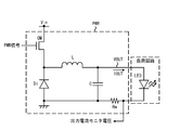
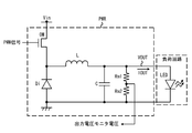
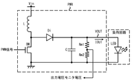
- FIG. 1 is a block diagram of a processor system to which the present invention is applied. It is a circuit diagram which shows the example of the power supply circuit controlled by the processor system shown in FIG. It is a circuit diagram which shows the example of the power supply circuit controlled by the processor system shown in FIG. It is a circuit diagram which shows the example of the power supply circuit controlled by the processor system shown in FIG. It is a circuit diagram which shows the example of the power supply circuit controlled by the processor system shown in FIG. It is a circuit diagram which shows the example of the power supply circuit controlled by the processor system shown in FIG.
- 1 is a block diagram of a PWM signal generation circuit according to a first exemplary embodiment
- 3 is a timing chart showing the operation of the PWM signal generation circuit according to the first exemplary embodiment
- 4 is a first timing chart showing a relationship between an initial duty value and a target duty value used in the PWM signal generation circuit according to the first embodiment and an output voltage of the power supply circuit.
- 6 is a second timing chart illustrating a relationship between an initial duty value and a target duty value used in the PWM signal generation circuit according to the first embodiment and an output voltage of the power supply circuit.
- 6 is a third timing chart illustrating a relationship between an initial duty value and a target duty value used in the PWM signal generation circuit according to the first embodiment and an output voltage of the power supply circuit.
- FIG. 6 is a fourth timing chart illustrating a relationship between a slope setting value used in the PWM signal generation circuit according to the first embodiment and an output voltage of the power supply circuit.
- FIG. 10 is a fifth timing chart illustrating a relationship between a slope setting value used in the PWM signal generation circuit according to the first embodiment and an output voltage of the power supply circuit.
- FIG. 3 is a block diagram of a PWM signal generation circuit according to a second exemplary embodiment. 6 is a detailed block diagram of a first example of an output monitor unit used in the second embodiment.
- FIG. FIG. 10 is a detailed block diagram of a second example of the output monitor unit used in the second embodiment. It is a 1st timing chart which shows the output voltage detection result using the output monitor unit shown in FIG. FIG.
- FIG. 6 is a block diagram of a PWM signal generation circuit according to a third exemplary embodiment. 6 is a timing chart showing a PWM signal generated by a PWM signal generation circuit according to a third embodiment and an output voltage generated by a power supply circuit based on the PWM signal. FIG. 6 is a block diagram of a PWM signal generation circuit according to a fourth exemplary embodiment.
- Embodiment 1 Embodiments of the present invention will be described below with reference to the drawings.
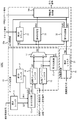
- FIG. 1 shows a schematic diagram of a processor system MCU to which the present invention is applied.
- the processor system MCU according to the present invention includes a memory MEM, a calculation core PE, a clock generation unit CG, a PWM signal generation unit PG, an output monitor unit MON, an IO unit IOU, and a peripheral circuit PERI.
- FIG. 1 shows the control target circuit PWR controlled by the processor system MCU.
- the control target circuit PWR is, for example, a power supply circuit, and generates and generates a boosted voltage obtained by boosting the power supply voltage based on a PWM signal generated by the PWM signal generation unit PG or a stepped down voltage obtained by reducing the power supply voltage.
- the power supply supplies the voltage to other circuits.
- the memory MEM stores programs used by the processor system MCU, setting values used for operating the processor system MCU, and the like.
- the arithmetic core PE performs specific processing required for the processor system MCU based on a program stored in the memory MEM or a program read from the outside.
- the clock generation unit CG generates a clock signal used in each circuit block in the processor system MCU.
- the clock signal generated by the clock generation unit CG may be output to the outside.
- the clock signal used in the processor system MCU can be supplied from an external circuit.
- PWM signal generation unit PG generates a PWM signal to be output to the outside.
- This PWM signal generation unit PG can also be realized by using the timer function of the processor system MCU, for example.
- the PWM signal generation unit PG may be mounted as a functional circuit different from the timer function.
- the output monitor unit MON monitors the voltage of the external circuit node. Then, the output monitor unit MON converts a voltage having an analog value into a digital value.
- the output monitor unit MON transmits the voltage level of the voltage value obtained from the outside as a digital value in the processor system MCU. In the example of FIG. 1, the output voltage of a power circuit provided outside can be monitored, and a digital value corresponding to the output voltage level can be taken into the processor system MCU.
- the output monitor unit MON can be configured by a circuit capable of converting an analog value into a digital value, such as an analog-digital converter (for example, ADC (Analog Digital Digital Converter)), a comparator circuit, or the like.
- the IO unit IOU communicates with an external circuit and receives a control signal to the processor system MCU or transmits a processing result of the processor system MCU.
- Specific examples of the IO unit IOU include an SPI unit and a UART unit.
- the SPI unit performs communication of SPI (System (Packet Interface) standard which is 3-wire or 4-wire serial communication.
- a UART (Universal Asynchronous Receiver Retransmitter) unit converts a serial signal according to an asynchronous method into a parallel signal and performs conversion in the opposite direction.
- the peripheral circuit PERI is a circuit other than the circuit blocks described above, and includes a circuit block used by the arithmetic core PE.
- a timer unit for example, a timer unit, a watchdog timer unit, a DMA (Direct Memory Access) unit, a low voltage detection unit, a power-on reset (POR) unit, or the like can be considered.
- DMA Direct Memory Access
- POR power-on reset
- the arithmetic core PE, the memory MEM, the PWM signal generation unit PG, the PWM signal generation unit PG, the output monitor unit MON, the IO unit IOU, and the peripheral circuit PERI are mutually connected by a bus. It becomes the composition which is done.
- power is supplied to the processor system MCU from another circuit.
- the processor system MCU described so far is an example of a processor system to which the present invention is applied.
- the program and data stored in the memory MEM can be appropriately changed according to the system specifications.
- the connection between the circuit blocks may be, for example, a configuration in which a plurality of buses are connected, and the arithmetic core PE and another circuit block are directly connected without via the bus. There may be.
- the processor system MCU can generate a PWM signal and give it to the control target circuit PWR.
- the processor system MCU can control the duty of the PWM signal, the generation timing of the PWM signal, or the like by the voltage of a node in the control target circuit, a control signal supplied from another circuit, or the like. Therefore, in order to clarify the usage form of the PWM signal generated by the processor system MCU, a power supply circuit which is an example of the control target circuit PWR will be described.
- the power supply circuit described below drives an LED (Light Emitting Diode) as a load circuit, but the load circuit is not limited to an LED, and may be a general circuit.
- FIGS. 2A to 2D show examples of power supply circuits for driving LEDs.
- the power supply circuit is denoted by PWR.
- an NMOS transistor is used as an output transistor for performing a switching operation.
- this output transistor can also be composed of a PMOS transistor, and can be composed of a PNP transistor or an NPN transistor. You can also
- the power supply circuit PWR shown in FIG. 2A is a step-down power supply circuit.
- the power supply circuit PWR includes an NMOS transistor OM, an inductor L, a diode Di, a capacitor C, and a resistor Rm.
- the drain of the NMOS transistor OM is connected to the power supply terminal to which the input voltage Vin is applied, and the source is connected to the cathode of the diode Di.
- a PWM signal is given to the gate of the NMOS transistor OM, and the NMOS transistor OM performs a switching operation according to the voltage level of the PWM signal.
- the anode of the diode Di is connected to the ground terminal.
- One end of the inductor L is connected to a node between the source of the NMOS transistor OM and the cathode of the diode Di.
- a capacitor C is connected between the other end of the inductor L and the ground terminal. Then, an output voltage VOUT corresponding to the amount of charge accumulated in the capacitor C is generated at a node between one end of the capacitor C and the other end of the inductor L. The electric charge accumulated in the capacitor C is supplied to the LED as an output current IOUT.
- a resistor Rm is connected between the cathode of the LED and the ground terminal. An output current IOUT flowing through the LED flows through the resistor Rm.
- a voltage corresponding to the output current IOUT and the resistance value of the resistor Rm is generated at both ends of the resistor Rm.
- This voltage is given to the output monitor unit MON of the processor system MCU as an output current monitor voltage.
- the processor system MCU generates a PWM signal having a duty ratio or frequency that makes the voltage level of the output current monitor voltage constant. That is, when the power supply circuit PWR shown in FIG. 2A is used, the processor system MCU and the power supply circuit PWR constitute a circuit that drives the LEDs with a constant current.
- the power supply circuit PWR shown in FIG. 2B is a boost type power supply circuit.
- the power supply circuit PWR includes an NMOS transistor OM, an inductor L, a diode Di, a capacitor C, and a resistor Rm.
- One end of the inductor is connected to a power supply terminal to which an input voltage Vin is applied.
- the drain of the NMOS transistor OM is connected to the other end of the inductor L, and the source is connected to the ground terminal.
- a PWM signal is given to the gate of the NMOS transistor OM, and the NMOS transistor OM performs a switching operation according to the voltage level of the PWM signal.
- the anode of the diode Di is connected to a node between the other end of the inductor L and the drain of the NMOS transistor OM.
- a capacitor C is connected between the cathode of the diode Di and the ground terminal. Then, an output voltage VOUT corresponding to the amount of charge accumulated in the capacitor C is generated at a node between one end of the capacitor C and the cathode of the diode Di.
- the electric charge accumulated in the capacitor C is supplied to the LED as an output current IOUT.
- a resistor Rm is connected between the cathode of the LED and the ground terminal. An output current IOUT flowing through the LED flows through the resistor Rm.
- a voltage corresponding to the output current IOUT and the resistance value of the resistor Rm is generated at both ends of the resistor Rm.
- This voltage is given to the output monitor unit MON of the processor system MCU as an output current monitor voltage.
- the processor system MCU generates a PWM signal having a duty ratio or frequency that makes the voltage level of the output current monitor voltage constant. That is, when the power supply circuit PWR shown in FIG. 2B is used, the processor system MCU and the power supply circuit PWR constitute a circuit that drives the LEDs with a constant current.
- the power supply circuit PWR shown in FIG. 2C is a step-down power supply circuit.
- the power supply circuit PWR includes an NMOS transistor OM, an inductor L, a diode Di, a capacitor C, and resistors Rm1 and Rm2.
- the drain of the NMOS transistor OM is connected to the power supply terminal to which the input voltage Vin is applied, and the source is connected to the cathode of the diode Di.
- a PWM signal is given to the gate of the NMOS transistor OM, and the NMOS transistor OM performs a switching operation according to the voltage level of the PWM signal.
- the anode of the diode Di is connected to the ground terminal.
- One end of the inductor L is connected to a node between the source of the NMOS transistor OM and the cathode of the diode Di.
- a capacitor C is connected between the other end of the inductor L and the ground terminal. Then, an output voltage VOUT corresponding to the amount of charge accumulated in the capacitor C is generated at a node between one end of the capacitor C and the other end of the inductor L. The electric charge accumulated in the capacitor C is supplied to the LED as an output current IOUT.
- resistors Rm1 and Rm2 are connected in series so as to be in parallel with the LED. That is, the output voltage VOUT applied to both ends of the LED is applied to both ends of the resistors Rm1 and Rm2.
- an output voltage monitor voltage obtained by dividing the output voltage VOUT by the resistance ratio of the two resistors is output from a node between the resistors Rm1 and Rm2.
- This voltage is given to the output monitor unit MON of the processor system MCU as an output voltage monitor voltage.
- the processor system MCU generates a PWM signal having a duty ratio or frequency that makes the voltage level of the output voltage monitor voltage constant. That is, when the power supply circuit PWR shown in FIG. 2C is used, the processor system MCU and the power supply circuit PWR constitute a circuit that drives the LEDs with a constant voltage.
- the power supply circuit PWR shown in FIG. 2D is a boost type power supply circuit.
- the power supply circuit PWR includes an NMOS transistor OM, an inductor L, a diode Di, a capacitor C, and resistors Rm1 and Rm2.
- One end of the inductor is connected to a power supply terminal to which an input voltage Vin is applied.
- the drain of the NMOS transistor OM is connected to the other end of the inductor L, and the source is connected to the ground terminal.
- a PWM signal is given to the gate of the NMOS transistor OM, and the NMOS transistor OM performs a switching operation according to the voltage level of the PWM signal.
- the anode of the diode Di is connected to a node between the other end of the inductor L and the drain of the NMOS transistor OM.
- a capacitor C is connected between the cathode of the diode Di and the ground terminal. Then, an output voltage VOUT corresponding to the amount of charge accumulated in the capacitor C is generated at a node between one end of the capacitor C and the cathode of the diode Di.
- the electric charge accumulated in the capacitor C is supplied to the LED as an output current IOUT.
- resistors Rm1 and Rm2 are connected in series so as to be in parallel with the LED. That is, the output voltage VOUT applied to both ends of the LED is applied to both ends of the resistors Rm1 and Rm2.
- an output voltage monitor voltage obtained by dividing the output voltage VOUT by the resistance ratio of the two resistors is output from a node between the resistors Rm1 and Rm2.
- This voltage is given to the output monitor unit MON of the processor system MCU as an output voltage monitor voltage.
- the processor system MCU generates a PWM signal having a duty ratio or frequency that makes the voltage level of the output voltage monitor voltage constant. That is, when the power supply circuit PWR shown in FIG. 2D is used, the processor system MCU and the power supply circuit PWR constitute a circuit that drives the LEDs with a constant voltage.
- processor system MCU is for explaining the overall configuration of the processor system to which the present invention is applied.
- components that have not been described in the description of the processor system MCU are added as appropriate.
- a description of the added component is also added.
- FIG. 3 shows a block diagram of the PWM signal generation circuit 1 included in the PWM signal generation unit PG.
- the PWM signal generation circuit 1 includes a duty setting unit 10, a cycle setting unit 20, and an output control unit 30.
- the PWM signal generation circuit 1 receives a clock signal, an initial duty setting signal, a target duty setting signal, a tilt setting signal, and a cycle setting signal.
- the initial duty setting signal, the target duty setting signal, the slope setting signal, and the cycle setting signal are given from the arithmetic core PE of the processor system MCU, but are given from other circuits. Also good.
- the initial duty setting signal specifies the initial duty ratio value at the start of PWM signal generation.
- the target duty setting signal specifies the value of the target duty ratio of the PWM signal.
- the inclination setting signal specifies an inclination setting value that specifies a change rate of the duty ratio from the initial duty ratio to the target duty ratio.
- the duty setting unit 10 generates a duty control signal DUT that specifies the duty ratio of the PWM signal for each cycle of the PWM signal based on the initial duty setting signal, the target duty setting signal, and the inclination setting signal. At this time, the duty setting unit 10 increases the value of the initial duty ratio to the value of the target duty ratio every time the number of times the number of clocks of the clock signal reaches the value of the period setting signal reaches the value of the inclination setting signal.
- the number of times that the number of clocks of the clock signal has reached the value of the period setting signal can be obtained by counting the number of pulses of the period start signal CRS1 described later.
- the duty setting unit 10 includes a first counter 12, a first comparator 13, a second comparator 16, and a selection circuit 17. Further, the duty setting unit 10 includes a slope register 11, an initial duty register 14, and a target duty register 15.
- the inclination register 11 stores an inclination setting value SLP given by an inclination setting signal.
- the initial duty register 14 stores an initial duty ratio value (hereinafter referred to as an initial duty value SRT) given by an initial duty setting signal.
- the target duty register 15 stores a target duty ratio value (hereinafter referred to as a target duty value TGT) given by the target duty setting signal.
- the first counter 12 generates the first count value CNT1 by counting the number of times the number of clocks of the clock signal has reached the value of the period setting signal, that is, the number of pulses of the period start signal CRS1.
- the first comparator 13 resets the first count value CNT1 to the count start value and increases the initial duty ratio value in response to the first count value CNT1 reaching the slope setting value. More specifically, the first comparator 13 asserts a first reset signal CLR1 to be given to the first counter 12 in response to the first count value CNT1 reaching the slope setting value. Then, the first counter 12 resets the first count value CNT1 to a count start value (for example, 1) in response to the assertion of the first reset signal CLR1.
- the first comparator 13 asserts an addition instruction signal ADD that increases the initial duty value SRT in response to the first count value CNT1 reaching the slope setting value SLP. Then, the initial duty register 14 increases the stored initial duty value SRT in response to the addition instruction signal ADD being asserted (for example, by adding 1 to the stored initial duty value SRT, Duty value SRT is updated).
- the second comparator 16 generates a selection signal SEL indicating the magnitude relationship between the initial duty value SRT stored in the initial duty register 14 and the target duty value TGT stored in the target duty register 15. More specifically, the second comparator 16 sets the selection signal SEL to the first logic level (for example, 0) when the target duty value is smaller than the initial duty value SRT. The second comparator 16 sets the selection signal SEL to the second logic level (for example, 1) when the initial duty value SRT is equal to or greater than the target duty value TGT.
- the selection circuit 17 outputs either the initial duty value SRT or the target duty value TGT as the duty control signal DUT according to the logic level of the selection signal SEL. More specifically, the selection circuit 17 outputs the initial duty value SRT as the duty control signal DUT when the selection signal SEL indicates 0. The selection circuit 17 sets the target when the selection signal SEL indicates 1. Duty value TGT is output as duty control signal DUT.
- the cycle setting unit 20 outputs a cycle setting value TRM indicating the length of one cycle of the PWM signal based on the cycle setting signal. More specifically, the cycle setting unit 20 includes a cycle register 21. The period register 21 stores a period setting value TRM indicated by the period setting signal. Then, the period setting unit 20 outputs the period setting value TRM stored in the period register 21.
- the output control unit 30 generates a PWM signal having a cycle according to the cycle set value and a duty ratio according to the value of the duty control signal based on the clock signal.
- the output control unit 30 includes a second counter 31, a third comparator 32, a fourth comparator 33, and a PWM signal generator 34.
- the second counter 31 counts the number of clocks of the clock signal to generate a second count value CNT2.
- the third comparator 32 receives the cycle set value TRM and the second count value CNT2.
- the third comparator 32 resets the second count value CNT2 to the count start value and notifies the cycle start in response to the second count value CNT2 reaching the cycle setting value TRM.
- a start signal CRS1 is output. More specifically, the second comparator 32 asserts a second reset signal CLR2 to be given to the second counter 31 in response to the second count value CNT2 reaching the cycle setting value TRM. Then, the second counter 31 resets the second count value CNT2 to a count start value (for example, 1) in response to the assertion of the second reset signal CLR2.
- the fourth comparator 33 outputs a switching signal CRS2 instructing switching of the logic level of the PWM signal in response to the second count value CNT2 reaching the value indicating the duty ratio indicated by the duty control signal DUT. To do.
- the PWM signal generator 34 sets the logic level of the output signal (PWM signal) as a start logic level according to the cycle start signal CRS1, and sets the logic level of the PWM signal as a logic level opposite to the start logic level according to the switching signal CRS2.
- the end logic level is as follows. In this embodiment, the logic level (start logic level) at the start of one cycle of the output PWM signal is set to 1, and the logic level (end logic level) at the end of one cycle of the PWM signal is set to 0. .
- the PWM signal generation circuit 1 stores the initial duty value SRT, the target duty value TGT, the slope setting value SLP, and the period setting value TRM in accordance with the initial duty setting signal, the target duty setting signal, the inclination setting signal, and the period setting signal.
- the generation process of the PWM signal is started in response to the storage.
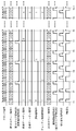
- FIG. 4 shows a timing chart showing an operation in which the PWM signal generation circuit generates a PWM signal in accordance with these set values. As shown in FIG. 4, the PWM signal generation circuit 1 proceeds with the generation process of the PWM signal in synchronization with the clock signal.
- the initial duty value SRT, the target duty value TGT, the slope setting value SLP, and the cycle setting value TRM are stored in the corresponding registers.
- 1 is set as the initial duty value SRT
- 3 is set as the target duty value TGT
- 2 is set as the slope setting value SLP
- 4 is set as the cycle setting value TRM. Is done.
- the first counter 12 starts counting the number of pulses of the period start signal CRS1 in response to the setting values being set in the register, and the second counter 31 starts counting the number of clocks of the clock signal. .
- the second comparator 16 sets the selection signal SEL to 0.
- the selection circuit 17 outputs the initial duty value SRT (1 in the example shown in FIG. 4) as the duty control signal DUT. Since the value of the duty control signal DUT is the same as the second count value CNT2 at the timing t1, the fourth comparator 33 sets the switching signal CRS2 to the high level until the next clock signal is input. And Then, in response to the transition of the second count value CNT2 to 2, the fourth comparator 33 sets the switching signal CRS2 to the low level.
- the PWM signal generator 34 switches the PWM signal from the high level to the low level. Subsequently, when the second count value CNT2 reaches the cycle set value TRM (4 in the example shown in FIG. 4), the third comparator 32 performs a cycle start signal for a period during which the second count value CNT2 is 4. CRS1 is set to high level. Further, the third comparator 32 asserts the second reset signal CLR2 (for example, high level) during the period when the second count value CNT2 is 4. In response to the second reset signal CLR2, the second count value CNT2 is reset to a count initial value (for example, 1) at timing t2.
- a count initial value for example, 1
- the PWM signal generator 34 sets the PWM signal to the initial logic level (for example, high level) according to the falling edge of the cycle start signal CRS1.
- the second count value CNT2 changes from 1 to 4 in accordance with the clock signal.
- the output control unit 30 repeats the operation from timing t1 to t2.
- the first count value CNT1 continues to count the cycle start signal CRS1 in the period from timing t1 to t3 without being reset at timing t2. That is, the first count value CNT1 changes from 1 to 2 during the period from the timing t1 to t3.
- the first comparator 13 performs the first comparator 13 during the period in which the first count value CNT1 is 2.
- the reset signal CLR1 and the addition instruction signal ADD are asserted (set to high level). Then, in response to the assertion of the first reset signal CLR1, the first count value CNT1 is reset to a count initial value (for example, 1).
- the initial duty register 14 updates the initial duty value SRT with a value obtained by adding one initial duty value SRT.
- the initial duty value SRT maintains the same value during the period until the first count value CNT1 reaches the slope setting value SLP because the addition instruction signal ADD is negated. Therefore, during the period from timing t1 to t3, the value indicated by the duty control signal DUT maintains the same value. That is, the duty ratio of the PWM signal is the same during the period from timing t1 to t3.
- the second comparator 16 sets the selection signal SEL to 0.
- the selection circuit 17 outputs the initial duty value SRT (2 in the example shown in FIG. 4) as the duty control signal DUT.
- the fourth comparator is used until the next clock signal is input. 33 sets the switching signal CRS2 to high level.
- the fourth comparator 33 sets the switching signal CRS2 to the low level.
- the PWM signal generator 34 switches the PWM signal from the high level to the low level. Subsequently, when the second count value CNT2 reaches the cycle set value TRM (4 in the example shown in FIG. 4), the third comparator 32 performs a cycle start signal for a period during which the second count value CNT2 is 4. CRS1 is set to high level. Further, the third comparator 32 asserts (for example, high level) the second reset signal CLR2 while the second count value CNT2 is four. In response to the second reset signal CLR2, the second count value CNT2 is reset to a count initial value (for example, 1) at timing t4.
- the PWM signal generator 34 sets the PWM signal to the initial logic level (for example, high level) according to the falling edge of the cycle start signal CRS1.
- the second count value CNT2 changes from 1 to 4 in accordance with the clock signal.
- the output control unit 30 repeats the operations from timing t3 to t4.
- the first count value CNT1 continues to count the cycle start signal CRS1 in the period from the timing t3 to t5 without being reset at the timing t4. That is, the first count value CNT1 changes from 1 to 2 during the period from the timing t3 to t5.
- the first comparator 13 performs the first comparator 13 during the period in which the first count value CNT1 is 2.
- the reset signal CLR1 and the addition instruction signal ADD are asserted (set to high level). Then, in response to the assertion of the first reset signal CLR1, the first count value CNT1 is reset to a count initial value (for example, 1).
- the initial duty register 14 updates the initial duty value SRT with a value obtained by adding one initial duty value SRT.
- the initial duty value SRT maintains the same value during the period until the first count value CNT1 reaches the slope setting value SLP because the addition instruction signal ADD is negated. Therefore, during the period from timing t3 to t5, the value indicated by the duty control signal DUT maintains the same value. That is, the duty ratio of the PWM signal is the same during the period from the timing t3 to t5. In the period from timing t3 to t5, the value of the duty control signal DUT is larger than that in the period from timing t1 to t3. Therefore, the duty ratio of the PWM signal is generated at timing t3 to t5 from that generated at timing t1 to t3. What is done is bigger.
- the second comparator 16 sets the selection signal SEL to 1.
- the selection circuit 17 outputs the target duty value TGT (3 in the example shown in FIG. 4) as the duty control signal DUT.
- the fourth comparator is used until the next clock signal is input. 33 sets the switching signal CRS2 to high level. Then, in response to the transition of the second count value CNT2 to 4, the fourth comparator 33 sets the switching signal CRS2 to the low level.
- the PWM signal generator 34 switches the PWM signal from the high level to the low level. Subsequently, when the second count value CNT2 reaches the cycle set value TRM (4 in the example shown in FIG. 4), the third comparator 32 performs a cycle start signal for a period during which the second count value CNT2 is 4. CRS1 is set to high level. Further, the third comparator 32 asserts (for example, high level) the second reset signal CLR2 while the second count value CNT2 is four. In response to the second reset signal CLR2, the second count value CNT2 is reset to a count initial value (for example, 1) at timing t6.
- a count initial value for example, 1
- the PWM signal generator 34 sets the PWM signal to the initial logic level (for example, high level) according to the falling edge of the cycle start signal CRS1.
- the second count value CNT2 changes from 1 to 4 in accordance with the clock signal.
- the output control unit 30 repeats the operations from timing t5 to t6.
- the first count value CNT1 continues to count the cycle start signal CRS1 in the period from timing t5 to t7 without being reset at timing t6. That is, the first count value CNT1 changes from 1 to 2 during the period from the timing t5 to t7.
- the first comparator 13 performs the first comparator 13 during the period in which the first count value CNT1 is 2.
- the reset signal CLR1 and the addition instruction signal ADD are asserted (set to high level). Then, in response to the assertion of the first reset signal CLR1, the first count value CNT1 is reset to a count initial value (for example, 1).
- the initial duty register 14 updates the initial duty value SRT with a value obtained by adding one initial duty value SRT.
- the target duty value TGT maintains a value equal to or lower than the initial duty value SRT. Therefore, in the period after timing t5, the value indicated by the duty control signal DUT maintains the same value (target duty value TGT). That is, the duty ratio of the PWM signal is the same during the period after timing t5. In the period after the timing t5, the value of the duty control signal DUT becomes larger than the period from the timing t3 to t5. For this reason, the duty ratio of the PWM signal is greater when it is generated after timing t5 than when it is generated at timing t3 to t5.
- the power supply circuit for example, the power supply circuit PWR in FIG. 2B.
- FIGS. 5 to 7 The relationship among the initial duty value SRT, target duty value TGT, slope setting value SLP and output voltage used in the PWM signal generation circuit 1 according to the first embodiment will be described with reference to FIGS.
- the target duty value TGT and the slope setting value SLP are constant.
- the initial duty value SRT and the target duty value SRT are constant. did.
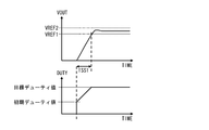
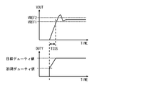
- the first timing chart shown in FIG. 5 shows the rising waveform of the output voltage when the initial duty value SRT and the target duty value TGT are appropriately set.
- the output voltage stabilizes at a voltage level between the target lower limit value VREF1 and the target upper limit value VREF2 after exceeding the target lower limit value VREF1.
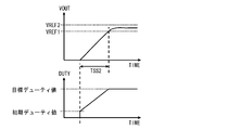
- the initial duty value SRT is made smaller than the example shown in the first timing chart.
- the slope setting value SLP is the same as in the example shown in FIG. 5
- the time TSS2 required for the output voltage to reach the target lower limit value VREF1 is longer than TSS1 in FIG. At this time, a problem arises when the time TSS2 becomes longer than the standard value.
- the initial duty value SRT is made larger than the example shown in the first timing chart.
- the slope setting value SLP is the same as that shown in FIG. 5
- the time TSS2 required for the output voltage to reach the target lower limit value VREF1 is shorter than TSS1 in FIG.
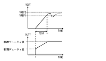
- the slope setting value SLP is made smaller than the example shown in the first timing chart.
- the time TSS4 required for the output voltage to reach the target lower limit value VREF1 is longer than TSS1 in FIG.
- the output voltage exceeds the target lower limit value VREF1
- the slope setting value SLP is made larger than the example shown in the first timing chart.
- the time TSS5 required for the output voltage to reach the target lower limit value VREF1 is shorter than TSS1 in FIG.
- the example shown in FIG. 9 has a problem that overshoot occurs when the output voltage rises.
- the initial duty value SRT, the target duty value TGT, and the slope setting value SLP are set so as to be in advance so that the output voltage has a rising waveform as shown in FIG.
- These set values can be optimized by measuring the output voltage in advance using the PWM signal generation circuit 1 and obtaining the optimum values. Note that the final voltage level of the output voltage can be increased or decreased by increasing or decreasing the target duty value TGT.
- the PWM signal generation circuit 1 starts generating a PWM signal in response to the initial duty value SRT, the target duty value TGT, the slope setting value SLP, and the cycle setting value TRM being set. To do. At this time, the PWM signal generation circuit 1 according to the first embodiment directly determines the duty ratio of the PWM signal from these set values. That is, the PWM signal generation circuit 1 can determine the duty ratio of the PWM signal without calculation when starting the generation of the PWM signal. Since the PWM signal generation circuit 1 needs a reference voltage supplied as an analog voltage or the like, generation of a PWM signal can be started without waiting for the rise of these voltages. For this reason, the PWM signal generation circuit 1 can generate a PWM signal immediately after the start of PWM signal generation.
- the PWM signal generation circuit 1 generates a PWM signal in synchronization with the clock signal, and varies the duty ratio of the PWM signal according to the count number of the clock signal.
- the PWM signal generation circuit 1 only performs a process of updating the value according to the count value of the number of clocks when the duty ratio is varied. For this reason, the PWM signal generation circuit 1 can perform soft start control of the PWM signal while simplifying the processing related to the calculation.
- the rising characteristics of the voltage output from the power supply circuit and the like are optimized by changing the setting values of the initial duty value SRT, the target duty value TGT, and the slope setting value SLP.
- the load circuit driven by the power supply circuit is an LED
- the overshoot of the output voltage has a problem of shortening the lifetime of the LED.
- undershoot occurs in the output voltage for driving the LED, there is a problem that causes flickering.
- the rising waveform of the PWM signal can be optimized by the set value, so that the above problem in the control target circuit (power supply circuit and load circuit) is easily solved. be able to.
- the PWM signal generation circuit 1 according to the first embodiment can be configured by a circuit having a small circuit scale such as a counter, a register, a comparator, and a selection circuit. Thereby, the PWM signal generation circuit 1 according to the first exemplary embodiment can reduce the circuit scale and the chip area.
- Embodiment 2 In the second embodiment, a method for automatically adjusting the initial duty value SRT, the target duty value TGT, the slope setting value SLP, and the like used in the PWM signal generation operation according to the first embodiment will be described.
- the setting value adjustment method according to the second embodiment uses the arithmetic core PE, the output monitor unit MON, the memory MEM, and the PWM signal generation unit PG shown in FIG.
- the PWM signal generation circuit 2 is used as the PWM signal generation unit PG.
- FIG. 10 shows a block diagram of the PWM signal generation circuit 2 according to the second exemplary embodiment.
- the PWM signal generation circuit 2 is obtained by adding an operation control function based on the PWM signal generation start signal to the PWM signal generation circuit 1 according to the first embodiment.
- a first counter 12 a is provided instead of the first counter 12
- a second counter 31 a is provided instead of the second counter 31.
- the first counter 12a generates the first count value CNT1 by counting the number of times the number of clocks of the clock signal reaches the value of the period setting signal, that is, the number of pulses of the period start signal CRS1.
- the first counter 12a resets the first count value CNT1 to the count start value in response to the assertion of the first clear signal CLR1. Further, the first counter 12a counts the number of clock signals when the PWM signal generation start signal is asserted, and counts the number of clock signals when the PWM signal generation start signal is negated. To stop.
- the second counter 31a counts the number of clock signals to generate a second count value CNT2. In addition, the second counter 31a resets the second count value CNT2 to the count start value in response to the assertion of the second clear signal CLR2. Further, the second counter 31a counts the clock number of the clock signal when the PWM signal generation start signal is asserted, and counts the clock number of the clock signal when the PWM signal generation start signal is negated. To stop.
- the PWM signal generation circuit 2 stops generating the PWM signal because the clock signal is not counted.
- the PWM signal generating circuit 2 generates a PWM signal in accordance with the clock signal counting operation. That is, the PWM signal generation start signal is a signal that controls the start and stop of the PWM signal generation process of the PWM signal generation circuit 2. In the second embodiment, it is assumed that the PWM signal generation start signal is a signal for the arithmetic core PE to control assertion and negation.
- FIG. 11 shows an example of the output monitor unit MON.
- the output monitor unit 40 shown in FIG. 11 includes comparators COMP1 and COMP2, and a time series information storage register 41.
- the monitor voltage obtained from the control target circuit (for example, the power supply circuit PWR) is input to the normal rotation input terminal, and the target lower limit value VREF1 is input to the inverting input terminal.
- the comparator COMP1 sets the output signal (for example, the lower limit detection signal) to a high level when the monitor voltage is larger than the target lower limit value VREF1.
- the monitor voltage obtained from the power supply circuit PWR is input to the normal rotation input terminal, and the target upper limit value VREF2 is input to the inverting input terminal.
- the comparator COMP2 sets the output signal (for example, the upper limit detection signal) to a high level when the monitor voltage is larger than the target upper limit value VREF2.
- the time-series information storage register 41 receives a clock signal (for example, a signal similar to the clock signal given to the PWM signal generation circuit 2) and a PWM signal generation start signal.
- the time-series information storage register 41 accumulates the logic levels of the lower limit detection signal and the upper limit detection signal using the clock signal as a sampling clock during the period when the PWM signal generation start signal is asserted. That is, in the time series information storage register 41, time series information of measurement values is generated with the time point when the PWM signal generation start signal is asserted as the start time point and the time point when the PWM signal generation start signal is negated as the end time point.
- the This time series information is referred to by the operation core PE.
- FIG. 12 is a block diagram showing another form of the output monitor unit MON.
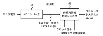
- the output monitor unit 50 shown in FIG. 12 includes an A / D converter 51 and a time series information storage register 52.
- the A / D converter 51 outputs a monitor voltage value signal corresponding to the voltage level of the monitor voltage obtained from the power supply circuit PWR.
- This monitor voltage value signal is a digital signal and has a value indicating the voltage level of the monitor voltage.
- the time series information storage register 52 receives a clock signal (for example, a signal similar to the clock signal given to the PWM signal generation circuit 2) and a PWM signal generation start signal.
- the time-series information storage register 41 accumulates the value of the monitor voltage value signal using the clock signal as a sampling clock during the period when the PWM signal generation start signal is asserted.
- the time-series information storage register 52 generates time-series information of measured values with the time when the PWM signal generation start signal is asserted as the start time and the time when the PWM signal generation start signal is negated as the end time.
- the This time series information is referred to by the operation core PE.
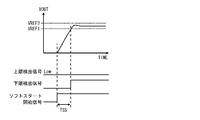
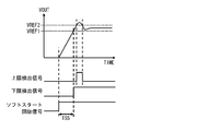
- FIGS. 13 to 15 are timing charts showing the relationship between the rising waveform of the output voltage generated in the power supply circuit and the change in the upper limit detection signal and the lower limit detection signal when the rising waveform of the output voltage is monitored.
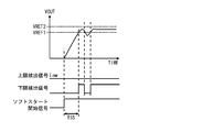
- the first timing chart shown in FIG. 13 shows a timing chart when the output voltage overshoot and undershoot are within a predetermined range determined by the target lower limit value VREF1 and the target upper limit value VREF2.
- the output voltage exceeds the target lower limit value VREF1 after the time TSS has elapsed since the PWM signal generation start signal was asserted. Therefore, the lower limit detection signal rises after the time TSS has elapsed since the PWM signal generation start signal was asserted. Thereafter, the lower limit detection signal maintains a high level.
- the upper limit detection signal maintains the low level.
- the second timing chart shown in FIG. 14 is a timing chart when the output voltage overshoot occurs.
- the output voltage exceeds the target lower limit value VREF1 after the time TSS has elapsed since the PWM signal generation start signal was asserted. Therefore, the lower limit detection signal rises after the time TSS has elapsed since the PWM signal generation start signal was asserted. Thereafter, the lower limit detection signal maintains a high level.
- the upper limit detection signal becomes high level in a period corresponding to a period in which the output voltage exceeds the target upper limit value VREF2.
- the third timing chart shown in FIG. 15 is a timing chart when the output voltage undershoot occurs.
- the output voltage exceeds the target lower limit value VREF1 after the time TSS has elapsed since the PWM signal generation start signal was asserted. Therefore, the lower limit detection signal rises after the time TSS has elapsed since the PWM signal generation start signal was asserted. Thereafter, the output voltage falls below the target lower limit value. Therefore, the lower limit detection signal is at a low level for a period corresponding to a period in which the output voltage falls below the target lower limit value. Then, when the output voltage again exceeds the target lower limit value VREF1, the lower limit detection signal becomes high level. On the other hand, since the output voltage does not exceed the target upper limit value VREF2, the upper limit detection signal maintains the low level.
- the output monitor unit 40 As shown in FIGS. 13 to 15, in the output monitor unit 40, the logic levels of the lower limit detection signal and the upper limit detection signal change according to the fluctuation of the output voltage. Then, the output monitor unit 40 records the time change of the output voltage by accumulating the logic levels of the lower limit detection signal and the upper limit detection signal in time series in the time series information storage register. Then, the calculation core PE refers to the time series information of the measurement values, so that the calculation core PE determines whether the fluctuation of the output voltage is appropriate and which parameter of the set value should be changed. Judgment can be made.
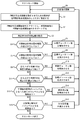
- FIG. 16 is a flowchart showing the procedure of the adjustment method according to the second embodiment.
- the arithmetic core PE performs processing according to the flowchart shown in FIG.
- the set value is adjusted during the period in which the computing core PE is in the test mode.
- the adjustment timing of the set value may be performed, for example, as one of the activation processes of the processor system MCU, or may be performed constantly.
- the arithmetic core PE reads a setting value (for example, an initial duty value) for operating the PWM signal generation circuit 2 from the memory MEM, and reads the read value. Store in the register of the PWM signal generation circuit 2 (step S1).
- a setting value for example, an initial duty value
- the operation core PE asserts the PWM signal generation start signal, and negates the PWM signal generation start signal after a predetermined time (step S2). Thereby, the PWM signal generation circuit 2 generates a PWM signal for a predetermined time. Further, the output monitor unit 40 generates time series information of measured values obtained by measuring the output voltage in the time series information storage register 41. Thereafter, the operation core PE acquires time series information from the time series information storage register 41 (step S3).
- the computing core PE refers to the value of the last period in the acquired time series information, and determines whether or not the value of the last period of the lower limit detection signal is low level (step S4).
- step S4 if the value of the final period of the lower limit detection signal is low level, the target duty value is increased (step S5).
- the arithmetic core PE updates the target duty value stored in the memory MEM with the increased target duty value (step S6). Thereafter, the arithmetic core PE executes the processes of steps S1 to S3 again.
- step S7 determines whether or not the value of the final period of the upper limit detection signal is high level (step S7).
- step S7 if the value of the final period of the upper limit detection signal is at a high level, the target duty value is decreased (step S8).
- the arithmetic core PE updates the target duty value stored in the memory MEM with the reduced target duty value (step S6). Thereafter, the arithmetic core PE executes the processes of steps S1 to S3 again.
- step S7 When the value of the final period of the upper limit detection signal is low level in step S7, the operation core PE determines whether or not the rise time TSS is longer than the specified range (step S9). In step S9, when the rising time TSS is longer than the specified range, the initial duty value is increased (step S10). Then, the computing core PE updates the initial duty value stored in the memory MEM with the increased initial duty value (step S6). Thereafter, the arithmetic core PE executes the processes of steps S1 to S3 again.
- step S9 the operation core PE determines whether the rise time TSS is shorter than the specified range (step S11). In step S11, when the rising time TSS is shorter than the specified range, the initial duty value is decreased (step S12). Then, the arithmetic core PE updates the initial duty value stored in the memory MEM with the reduced initial duty value (step S6). Thereafter, the arithmetic core PE executes the processes of steps S1 to S3 again.
- step S13 When the rise time TSS is longer than the specified range in step S11, the operation core PE determines whether or not there is a period during which the lower limit detection signal becomes low level after becoming high level (step S13). In step S13, when there is a period during which the lower limit detection signal becomes low level after becoming high level, the inclination set value is increased (step S14). Then, the operation core PE updates the inclination setting value stored in the memory MEM with the increased inclination setting value (step S6). Thereafter, the arithmetic core PE executes the processes of steps S1 to S3 again.
- step S15 determines whether or not there is a period in which the upper limit detection signal becomes high level.
- step S15 when there is a period during which the upper limit detection signal is at a high level, the inclination set value is decreased (step S16). Then, the operation core PE updates the inclination setting value stored in the memory MEM with the reduced inclination setting value (step S6). Thereafter, the arithmetic core PE executes the processes of steps S1 to S3 again.
- the test mode ends.
- the output voltage generated by receiving the PWM signal generated by the PWM signal generation circuit 2 that operates based on the adjusted set value causes overshoot and undershoot.
- the voltage value falls within the range between the target lower limit value VREF1 and the target upper limit value VREF2. That is, the output voltage has a rising waveform shown in FIG.
- the PWM signal generation circuit 2 that operates based on the set value determined through the adjustment method according to the second embodiment can generate a PWM signal that makes the operation of the control target circuit an ideal operation state. .
- the lifetime of the LED can be extended.
- the characteristics of LEDs change due to aging. Therefore, when the LED is controlled based on a PWM signal generated based on a fixed set value, deterioration such as a decrease in luminance occurs.
- a PWM signal for driving the LED while appropriately executing the adjustment method according to the second embodiment, it is possible to generate an output voltage that compensates for the deterioration of the characteristics of the LED.
- the lifetime of the LED can be substantially extended by generating the output voltage that compensates for the characteristic deterioration of the LED.
- the setting value updated by the setting value adjusting method according to the second embodiment is stored in the memory MEM. Therefore, when the processor system MCU is restarted, the setting value is read from the memory MEM so that the processor system MCU after the restart is optimized and adjusts the setting value of the PWM signal generation circuit 2 according to the setting value. The operation can be started in an optimized state without any problems.
- FIG. 17 shows a block diagram of the PWM signal generation circuit 3 according to the third exemplary embodiment.
- the PWM signal generation circuit 3 according to the third embodiment uses a PWM signal generator 34a instead of the PWM signal generator 34 of the PWM signal generation circuit 1 according to the first embodiment.
- the output control unit having the PWM signal generator 34a is denoted by reference numeral 30a.
- the PWM signal generator 34a receives a PWM output gate signal in addition to the cycle setting signal CRS1 and the switching signal CRS2.
- the PWM signal generator 34a performs the same operation as the PWM signal generator 34 when the PWM output gate signal is asserted. On the other hand, when the PWM output gate signal is negated, the PWM signal generator 34a stops generating the PWM signal.
- the PWM output gate signal is switched between assert and negate by the computation core PE.
- the arithmetic core PE asserts the slope setting value stored in the slope register 11 of the PWM signal generation circuit 3, the initial duty value stored in the initial duty register 14, and the target duty when the PWM output gate signal is asserted.
- the target duty value stored in the register 15 and the cycle set value stored in the cycle register 21 are set by the set values read from the memory MEM.
- FIG. 18 is a timing chart showing the operation of the PWM signal generation circuit 3 according to the third exemplary embodiment.
- the PWM signal generation circuit 3 according to the third exemplary embodiment starts generating a PWM signal when the PWM output gate signal is asserted at timing t11.
- the PWM signal generated at this time is subjected to soft start control.
- the output voltage of the power supply circuit generated based on the PWM signal subjected to soft start control rises without causing overshoot and undershoot.
- the PWM signal generation circuit 3 stops outputting the PWM signal, and the output voltage of the power supply circuit decreases.
- the PWM signal generation circuit 3 generates a PWM signal subjected to soft start control. Then, the output voltage of the power supply circuit rises based on the generated PWM signal.
- the PWM signal generation circuit 3 intermittently generates a PWM signal by intermittently asserting the PWM output gate signal. This intermittent interval can be determined by the ratio between the PWM output gate signal assertion period TH and the negation period TL.
- the PWM signal generation circuit 3 generates a PWM signal by soft start control every time the generation of the PWM signal is restarted.
- dimming can be performed by controlling the ratio between the assertion period TH and the negation period TL of the PWM output gate signal. This is because the luminance of the LED can be controlled by the integral value of the lighting time.
- the dimming control of the LED becomes possible by using the PWM signal generation circuit 3 according to the third embodiment.
- the PWM signal generation circuit 3 according to the third embodiment generates a PWM signal by soft start control every time the PWM output gate signal is asserted.
- the output signal of the power supply circuit rises without any overshoot or undershoot at any rise timing.
- a control signal (for example, a dimming control signal) is received from a circuit provided outside via the IO unit IOU of the processor system MCU, and the arithmetic core PE determines the PWM output gate signal based on the received dimming control signal. It is also possible to control the ratio between the assertion period TH and the negation period TL. With such a configuration, the processor system MCU having the PWM signal generation circuit 3 according to the third embodiment can perform LED light control based on an instruction from the outside.
- FIG. 19 shows a block diagram of the PWM signal generation circuit 4 according to the fourth exemplary embodiment.
- the PWM signal generation circuit 4 includes duty setting units 10a and 10b, a cycle setting unit 20, and an output control unit 30b. Since the cycle setting unit 20 is the same as the cycle setting unit of the first embodiment, description thereof is omitted here.
- the duty setting units 10a and 10b have the same configuration as the duty setting unit 10 of the first embodiment, but input independent setting signals.
- the duty setting unit 10a receives a first inclination setting signal, a first initial duty setting signal, and a first target duty setting signal.
- the duty setting unit 10b receives the second inclination setting signal, the second initial duty setting signal, and the second target duty setting signal.
- the duty setting units 10a and 10b output duty control signals DUT1 and DUT2 having independent values based on setting signals having independent values.
- the output control unit 30b includes a fifth comparator 35 added to the output control unit 30 of the first embodiment, and includes a PWM signal generator 34b instead of the PWM signal generator 34.
- the fifth comparator 35 outputs a switching signal CRS3 instructing switching of the logic level of the PWM signal in response to the second count value CNT2 reaching the value indicating the duty ratio indicated by the duty control signal DUT2.
- the fourth comparator 33 corresponds to the fourth comparator 33 of the first embodiment, but the duty control signal DUT1 is input as a signal corresponding to the duty control signal DUT.
- the PWM signal generator 34b sets the logic level of the first PWM signal as the start logic level according to the cycle start signal CRS1, and sets the logic level of the PWM signal as a logic level opposite to the start logic level according to the switching signal CRS2.
- the end logic level is as follows.
- the PWM signal generator 34b sets the logic level of the second PWM signal as the start logic level according to the cycle start signal CRS1, and sets the logic level of the PWM signal as a logic opposite to the start logic level according to the switching signal CRS3.
- the end logical level is the level. In this embodiment, the logic level (start logic level) at the start of one cycle of the output PWM signal is set to 1, and the logic level (end logic level) at the end of one cycle of the PWM signal is set to 0. .
- the output control unit 30b generates a plurality of PWM signals each having a duty ratio corresponding to the duty ratio value indicated by the duty control signals output from the plurality of duty setting units.
- the PWM signal generation circuit 4 according to the fourth exemplary embodiment generates the first and second PWM signals having the same cycle and independent duty ratios by the above configuration.
- the operation of the PWM signal generation circuit 4 is only increased by two signals to be output, and the substantial operation is the same as that of the PWM signal generation circuit 1 according to the first embodiment. To do.
- the PWM signal generation circuit 4 can set the duty ratio and the soft start control of the PWM signal independently.
- the number of output PWM signals is two.
- three PWM signals can be generated by applying the same rule as the change from the PWM signal generation circuit 1 to the PWM signal generation circuit 4.
- lighting devices using LEDs may use LEDs corresponding to the three colors. In such a case, the characteristics of the plurality of LEDs may vary.
- the PWM signal generation circuit 4 the characteristics of a plurality of PWM signals can be set independently. Therefore, by using the PWM signal generation circuit 4, it is possible to correct variations among a plurality of LEDs used as a set of light emitting elements and make the characteristics of the plurality of LEDs uniform.
- the method for adjusting the setting value of the PWM signal generation circuit according to the second embodiment can be applied to the PWM signal generation circuit 4 according to the fourth embodiment.
- a PWM signal intermittent output function of the PWM signal generation circuit 3 according to the fourth embodiment may be added.
Landscapes
- Engineering & Computer Science (AREA)
- Power Engineering (AREA)
- Dc-Dc Converters (AREA)
Abstract
Description
以下、図面を参照して本発明の実施の形態について説明する。
実施の形態2では、実施の形態1にかかるPWM信号生成動作で用いた初期デューティ値SRT、目標デューティ値TGT、傾き設定値SLP等を自動的に調節する方法について説明する。なお、実施の形態2にかかる設定値の調整方法では、図1に示した演算コアPE、出力モニタユニットMON、メモリMEM、PWM信号生成ユニットPGを利用する。また、実施の形態2では、PWM信号生成ユニットPGとしてPWM信号生成回路2を用いる。
実施の形態3にかかるPWM信号生成回路3のブロック図を図17に示す。図17に示すように、実施の形態3にかかるPWM信号生成回路3は、実施の形態1にかかるPWM信号生成回路1のPWM信号生成器34に代えてPWM信号生成器34aが用いられる。図17では、このPWM信号生成器34aを有する出力制御部には30aの符号を付した。
実施の形態4にかかるPWM信号生成回路4のブロック図を図19に示す。図19に示すようにPWM信号生成回路4は、デューティ設定部10a、10b、周期設定部20、出力制御部30bを有する。周期設定部20は、実施の形態1の周期設定部と同じものであるため、ここでは説明を省略する。
10、10a、10b デューティ設定部
11 傾きレジスタ
12、12a、31、31a カウンタ
13、16、32、33、35 比較器
14 初期デューティレジスタ
15 目標デューティレジスタ
17 選択回路
20 周期設定部
21 周期レジスタ
30、30a、30b 出力制御部
34、34a、34b 信号生成器
40、50 出力モニタユニット
41、52 時系列情報格納レジスタ
51 A/Dコンバータ
C コンデンサ
L インダクタ
Di ダイオード
R 抵抗
OM トランジスタ
MCU プロセッサシステム
MEM メモリ
MON 出力モニタユニット
PE 演算コア
PERI 周辺回路
PG PWM信号生成ユニット
CG クロック生成ユニット
Claims (15)
- PWM信号を生成するPWM信号生成回路であって、
前記PWM信号の生成開始時の初期デューティ比の値を指定する初期デューティ設定信号と、前記PWM信号の目標デューティ比の値を指定する目標デューティ設定信号と、前記初期デューティ比が前記目標デューティ比に至るまでのデューティ比の変化率を指定する傾き設定値を指定する傾き設定信号と、クロック信号と、に基づき前記PWM信号の1周期毎のデューティ比を指定するデューティ制御信号を生成するデューティ設定部と、
周期設定信号に基づき前記PWM信号の1周期の長さを示す周期設定値を出力する周期設定部と、
前記周期設定値に応じた周期と前記デューティ制御信号の値に応じたデューティ比の前記PWM信号を前記クロック信号に基づき生成する出力制御部と、を有し、
前記デューティ設定部は、前記クロック信号のクロック数が前記周期設定値に達した回数が前記傾き設定値に達する毎に前記初期デューティの値を前記目標デューティ比の値まで増加させるPWM信号生成回路。 - 前記デューティ設定部は、
前記クロック信号のクロック数が前記周期設定値に達した回数をカウントして第1のカウント値を生成する第1のカウンタと、
前記第1のカウント値が前記傾き設定値に達したことに応じて、前記第1のカウント値をカウント開始値にリセットすると共に、前記初期デューティ比の値を増加させる第1の比較器と、
前記初期デューティ比の値と前記目標デューティ比の値との大小関係を示す選択信号を生成する第2の比較器と、
前記初期デューティ比の値より前記目標デューティ比の値の方が小さいことを前記選択信号が示している場合に前記初期デューティ比の値を出力し、前記初期デューティ比の値が前記目標デューティ比の値以上であること前記選択信号を示している場合に前記目標デューティ値を出力する選択回路と、
を有する請求項1に記載のPWM信号生成回路。 - 前記デューティ設定部は、
前記初期デューティ比の値を格納する初期デューティレジスタと、
前記目標デューティ比の値を格納する目標デューティレジスタと、
前記傾き設定値を格納する傾きレジスタと、を有し、
前記周期設定部は、
前記周期設定値を格納する周期レジスタを有する請求項1又は2に記載のPWM信号生成回路。 - 前記出力制御部は、
前記クロック信号のクロック数をカウントして第2のカウント値を生成する第2のカウンタと、
前記周期設定値と、前記第2のカウント値と、が入力され、前記第2のカウント値が前記周期設定値に達したことに応じて、前記第2のカウント値をカウント開始値にリセットすると共に、周期開始を通知する周期開始信号を出力する第3の比較器と、
前記デューティ制御信号で示されるデューティ比を示す値に前記第2のカウント値が達したことに応じて、前記PWM信号の論理レベルの切り換えを指示する切り換え信号を出力する第4の比較器と、
前記周期開始信号に応じて前記PWM信号の論理レベルを開始論理レベルとし、前記切り換え信号に応じて前記PWM信号の論理レベルを前記開始論理レベルとは逆の論理レベルとなる終了論理レベルとするPWM信号生成器と、
を有する請求項1乃至3のいずれか1項に記載のPWM信号生成回路。 - 前記PWM信号生成器は、PWM出力ゲート信号が入力され、前記PWM信号ゲート信号の論理レベルに応じて前記PWM信号を出力するか否かを切り換える請求項4に記載のPWM信号生成回路。
- 前記PWM信号生成回路は、
前記デューティ設定部を複数個有し、
前記出力制御部は、それぞれが、複数のデューティ設定部が出力するデューティ制御信号で示されるデューティ比の値に対応するデューティ比を有する複数のPWM信号を生成する請求項1乃至5のいずれか1項に記載のPWM信号生成回路。 - 外部に設けられた制御対象回路にPWM信号を出力するプロセッサシステムであって、
前記プロセッサシステムで用いられるプログラム及び設定値を格納するメモリと、
PWM信号生成ユニットと、
演算コアと、を有し、
前記PWM信号生成ユニットは、
前記PWM信号の生成開始時の初期デューティ比の値を指定する初期デューティ設定信号と、前記PWM信号の目標デューティ比の値を指定する目標デューティ設定信号と、前記初期デューティ比が前記目標デューティ比に至るまでのデューティ比の変化率を指定する傾き設定値を指定する傾き設定信号と、クロック信号と、に基づき前記PWM信号の1周期毎のデューティ比を指定するデューティ制御信号を生成するデューティ設定部と、
周期設定信号に基づき前記PWM信号の1周期の長さを示す周期設定値を出力する周期設定部と、
前記周期設定値に応じた周期と前記デューティ制御信号の値に応じたデューティ比の前記PWM信号を前記クロック信号に基づき生成する出力制御部と、を有し、
前記デューティ設定部は、前記クロック信号のクロック数が前記周期設定値に達した回数が前記傾き設定値に達する毎に前記初期デューティ比の値を前記目標デューティ比の値まで増加させ、
前記演算コアは、
前記プログラム及び前記設定値を読み出して前記初期デューティ設定信号、前記目標デューティ設定信号、前記傾き設定信号及び前記周期設定信号を生成して、前記PWM信号生成ユニットに与えるプロセッサシステム。 - 前記演算コアは、PWM信号生成開始信号を出力し、
前記PWM信号生成ユニットは、前記PWM信号生成開始信号に応じて前記PWM信号の生成を開始する請求項7に記載のプロセッサシステム。 - 前記制御対象回路内のノードに生成される電圧のレベルを示す計測値の時系列情報を生成する出力モニタユニットを有し、
前記出力モニタユニットは、前記PWM信号生成開始信号に応じて前記計測値の時系列情報の生成を開始する請求項8に記載のプロセッサシステム。 - 前記演算コアは、
前記計測値の時系列情報の最終値が予め設定された目標下限値を下回っている場合、前記目標デューティ比の値を増加させ、
前記計測値の時系列情報の最終値が予め設定された目標上限値を上回っている場合、前記目標デューティ比の値を減少させ、
前記計測値の時系列情報の開始時点から前記測定値が前記目標下限値を最初に上回るまでの時間が予め設定された立ち上がり時間より短い場合、前記初期デューティ比の値を増加させ、
前記計測値の時系列情報の開始時点から前記測定値が前記目標下限値を最初に上回るまでの時間が予め設定された立ち上がり時間より長い場合、前記初期デューティ比の値を減少させ、
前記計測値が前記目標下限値を最初に上回った後再度前記目標下限値を下回った場合、前記傾き設定値を増加させ、
前記計測値が前記目標上限値を最初に上回った後再度前記目標上限値を下回った場合、前記傾き設定値を減少させ、
前記メモリに格納されている設定値に含まれる前記目標デューティ比の値、初期デューティ比の値及び前記傾き設定値を更新する請求項9に記載のプロセッサシステム。 - 前記演算コアは、前記PWM信号生成開始信号を出力する毎に前記メモリから前記設定値を読み出して前記初期デューティ設定信号、前記目標デューティ設定信号、前記傾き設定信号及び前記周期設定信号を前記PWM信号生成ユニットに与える請求項8乃至10のいずれか1項に記載のプロセッサシステム。
- 前記演算コアは、前記PWM信号生成開始信号により前記PWM信号生成ユニットが前記PWM信号を間欠的出力するように制御する請求項8乃至11のいずれか1項に記載のプロセッサシステム。
- 外部に設けられた回路から与えられる制御信号を受信するIOユニットを有し、
前記演算コアは、前記IOユニットを介して得た前記制御信号に基づき前記PWM信号生成ユニットによる前記PWM信号の出力の開始及び停止を指示するPWM出力ゲート信号を生成し、前記PWM出力ゲート信号により前記PWM信号生成ユニットが前記PWM信号を出力する間隔を制御し、前記PWM信号の出力の開始指示を行う毎に前記メモリから前記設定値を読み出して前記初期デューティ設定信号、前記目標デューティ設定信号、前記傾き設定信号及び前記周期設定信号を前記PWM信号生成ユニットに与える請求項7に記載のプロセッサシステム。 - 前記制御対象回路は、スイッチング動作により出力電圧の電圧レベルを制御する電源回路である請求項7乃至13のいずれか1項に記載のプロセッサシステム。
- 前記電源回路は、LED素子を駆動する請求項14に記載のプロセッサシステム。
Priority Applications (5)
| Application Number | Priority Date | Filing Date | Title |
|---|---|---|---|
| US14/006,622 US8947145B2 (en) | 2011-03-28 | 2012-02-24 | PWM signal generation circuit and processor system |
| JP2013507107A JP5584824B2 (ja) | 2011-03-28 | 2012-02-24 | Pwm信号生成回路及びプロセッサシステム |
| CN201280016973.3A CN103493349B (zh) | 2011-03-28 | 2012-02-24 | Pwm信号生成电路和处理器系统 |
| KR1020137025655A KR101559221B1 (ko) | 2011-03-28 | 2012-02-24 | Pwm 신호 생성 회로 및 프로세서 시스템 |
| US14/564,801 US9419600B2 (en) | 2011-03-28 | 2014-12-09 | PWM signal generation circuit and processor system |
Applications Claiming Priority (2)
| Application Number | Priority Date | Filing Date | Title |
|---|---|---|---|
| JP2011070437 | 2011-03-28 | ||
| JP2011-070437 | 2011-03-28 |
Related Child Applications (2)
| Application Number | Title | Priority Date | Filing Date |
|---|---|---|---|
| US14/006,622 A-371-Of-International US8947145B2 (en) | 2011-03-28 | 2012-02-24 | PWM signal generation circuit and processor system |
| US14/564,801 Continuation US9419600B2 (en) | 2011-03-28 | 2014-12-09 | PWM signal generation circuit and processor system |
Publications (1)
| Publication Number | Publication Date |
|---|---|
| WO2012132221A1 true WO2012132221A1 (ja) | 2012-10-04 |
Family
ID=46930017
Family Applications (1)
| Application Number | Title | Priority Date | Filing Date |
|---|---|---|---|
| PCT/JP2012/001287 Ceased WO2012132221A1 (ja) | 2011-03-28 | 2012-02-24 | Pwm信号生成回路及びプロセッサシステム |
Country Status (5)
| Country | Link |
|---|---|
| US (2) | US8947145B2 (ja) |
| JP (1) | JP5584824B2 (ja) |
| KR (1) | KR101559221B1 (ja) |
| CN (1) | CN103493349B (ja) |
| WO (1) | WO2012132221A1 (ja) |
Cited By (2)
| Publication number | Priority date | Publication date | Assignee | Title |
|---|---|---|---|---|
| CN103607185A (zh) * | 2013-11-27 | 2014-02-26 | 矽力杰半导体技术(杭州)有限公司 | 产生脉宽调制信号的装置及方法 |
| JP2024070500A (ja) * | 2022-11-11 | 2024-05-23 | コーセル株式会社 | スイッチング電源装置と電源システム、及びスイッチング電源装置の初期設定方法 |
Families Citing this family (33)
| Publication number | Priority date | Publication date | Assignee | Title |
|---|---|---|---|---|
| JP2014092370A (ja) * | 2012-10-31 | 2014-05-19 | Agilent Technologies Inc | 電圧電流特性発生器 |
| DE102013210094A1 (de) * | 2013-04-12 | 2014-10-16 | Behr Gmbh & Co. Kg | Wärmeübertragerbauteil |
| US9351373B2 (en) * | 2013-08-23 | 2016-05-24 | Chia-Teh Chen | Security light with lifestyle solutions |
| US20160269016A1 (en) * | 2015-03-12 | 2016-09-15 | Microchip Technology Incorporated | Combinatorial/sequential pulse width modulation |
| US20180255614A1 (en) * | 2015-09-28 | 2018-09-06 | Kelsey-Hayes Company | Programmable led driver |
| JP6589765B2 (ja) * | 2016-07-19 | 2019-10-16 | 株式会社デンソー | 負荷駆動制御装置 |
| JP6966694B2 (ja) * | 2017-09-27 | 2021-11-17 | 富士通株式会社 | 電源装置及び電源管理プログラム |
| US20190132921A1 (en) * | 2017-10-31 | 2019-05-02 | Fulham Company Limited | Led dimming using switch mode power supply control loop parameter modification |
| US10595373B2 (en) | 2017-10-31 | 2020-03-17 | Fulham Company Limited | Methods and apparatuses to provide dimming for a light emitting diode system |
| US10015858B1 (en) * | 2017-12-12 | 2018-07-03 | GE Lighting Solutions, LLC | Deep dimming control in LED lighting system |
| US10367411B2 (en) * | 2017-12-20 | 2019-07-30 | Analog Devices Global Unlimited Company | Interleaved boost converter with holdup time extension |
| CN107995744B (zh) * | 2017-12-26 | 2024-07-23 | 深圳市联达奇科技有限公司 | 用于led照明的色彩偏差消除电路 |
| JP6962203B2 (ja) * | 2018-01-11 | 2021-11-05 | 株式会社デンソー | 昇圧システム |
| US11323052B2 (en) * | 2018-10-25 | 2022-05-03 | Microchip Technology Incorporated | Automated speed ramp control of stepper motors |
| CN109361381B (zh) | 2018-12-10 | 2024-05-03 | 珠海一微半导体股份有限公司 | 一种pwm生成电路、处理电路及芯片 |
| US11064589B2 (en) * | 2019-01-23 | 2021-07-13 | Whelen Engineering Company, Inc. | System and method for variable intensity patterns |
| US11039517B2 (en) * | 2019-04-01 | 2021-06-15 | Sct Ltd. | Fraction PWM with multiple phase display clock |
| CN111262563B (zh) * | 2020-03-19 | 2023-09-08 | 湖南品腾电子科技有限公司 | 大电流输出电路 |
| CN111555603B (zh) * | 2020-06-22 | 2021-05-11 | 无锡英迪芯微电子科技股份有限公司 | 一种降压转换器的自校准软启动电路 |
| US11955879B2 (en) * | 2020-12-30 | 2024-04-09 | Texas Instruments Incorporated | Architecture to mitigate overshoot/undershoot in a voltage regulator |
| CN112967670B (zh) * | 2021-03-03 | 2022-11-18 | 北京集创北方科技股份有限公司 | 显示驱动方法、装置和芯片、显示设备以及存储介质 |
| CN114002985A (zh) * | 2021-11-02 | 2022-02-01 | 湖南航天机电设备与特种材料研究所 | 一种基于fpga的pwm波形产生方法及装置 |
| CN114337266B (zh) * | 2021-12-17 | 2023-12-26 | 上海晶丰明源半导体股份有限公司 | 开关电源及用于开关电源的控制电路 |
| CN114221642B (zh) * | 2022-02-22 | 2022-06-17 | 浙江地芯引力科技有限公司 | Pwm波生成及占空比控制方法、装置、定时器及设备 |
| EP4250564A1 (en) * | 2022-03-23 | 2023-09-27 | NXP USA, Inc. | A controller for a power converter and a method of controlling a power converter |
| CN114721908B (zh) * | 2022-04-11 | 2022-12-06 | 摩尔线程智能科技(北京)有限责任公司 | 片上功耗控制电路、芯片以及功耗控制方法 |
| CN115133915A (zh) * | 2022-06-14 | 2022-09-30 | 华南理工大学 | 一种基于gpio和定时器的pwm信号生成方法 |
| CN115899973B (zh) * | 2022-11-24 | 2025-11-28 | 青岛海信日立空调系统有限公司 | 空调系统通信装置的信号调节方法、装置及空调系统 |
| US20240196494A1 (en) * | 2022-12-13 | 2024-06-13 | Lx Semicon Co., Ltd. | Pulse width modulation signal generation circuit and lamp control system including the same |
| CN116398461A (zh) * | 2023-05-16 | 2023-07-07 | 上海申矽凌微电子科技股份有限公司 | 风扇控制方法及系统 |
| KR102818664B1 (ko) | 2023-10-16 | 2025-06-12 | 고려대학교 산학협력단 | 공진 조정 정류기 |
| CN119921738A (zh) * | 2023-10-31 | 2025-05-02 | 新唐科技股份有限公司 | 输入讯号重构装置、方法与使用其的电子设备 |
| KR20250153597A (ko) | 2024-04-18 | 2025-10-27 | 고려대학교 산학협력단 | 포락선 검출기가 필요 없는 정방향 데이터 수신 장치 |
Citations (4)
| Publication number | Priority date | Publication date | Assignee | Title |
|---|---|---|---|---|
| JPH05161262A (ja) * | 1991-11-29 | 1993-06-25 | Oki Electric Ind Co Ltd | 直流給電回路 |
| JP2004159473A (ja) * | 2002-11-08 | 2004-06-03 | Toyota Industries Corp | 絶縁型電圧変換回路 |
| WO2008041666A1 (en) * | 2006-10-02 | 2008-04-10 | Panasonic Corporation | Dc/dc converter |
| JP2009112168A (ja) * | 2007-10-31 | 2009-05-21 | Sharp Corp | スイッチング電源回路及び電子機器 |
Family Cites Families (10)
| Publication number | Priority date | Publication date | Assignee | Title |
|---|---|---|---|---|
| JP2838133B2 (ja) * | 1993-03-10 | 1998-12-16 | サンケン電気株式会社 | 電力変換装置 |
| JPH0974737A (ja) | 1995-09-01 | 1997-03-18 | Canon Inc | Pwm信号生成装置 |
| JP3817958B2 (ja) * | 1999-03-16 | 2006-09-06 | セイコーエプソン株式会社 | Pwm制御回路、マイクロコンピュータ、及び電子機器 |
| JP3675339B2 (ja) | 2001-01-18 | 2005-07-27 | 株式会社日立製作所 | スイッチング電源 |
| JP3738014B2 (ja) | 2003-03-28 | 2006-01-25 | Tdk株式会社 | スイッチング電源のソフトスタート方法、出力制御回路およびスイッチング電源 |
| JP4265498B2 (ja) * | 2004-07-06 | 2009-05-20 | ブラザー工業株式会社 | モータ制御方法及び制御装置 |
| JP4368787B2 (ja) * | 2004-12-15 | 2009-11-18 | Smk株式会社 | パルス幅変調信号生成装置及びパルス幅変調信号の生成方法 |
| JP4840328B2 (ja) * | 2007-10-25 | 2011-12-21 | 住友電装株式会社 | Pwm制御方法及び装置、並びに、調光装置 |
| US7791386B2 (en) * | 2008-01-23 | 2010-09-07 | Microchip Technology Incorporated | Externally synchronizing multiphase pulse width modulation signals |
| US8040070B2 (en) * | 2008-01-23 | 2011-10-18 | Cree, Inc. | Frequency converted dimming signal generation |
-
2012
- 2012-02-24 WO PCT/JP2012/001287 patent/WO2012132221A1/ja not_active Ceased
- 2012-02-24 US US14/006,622 patent/US8947145B2/en active Active
- 2012-02-24 KR KR1020137025655A patent/KR101559221B1/ko active Active
- 2012-02-24 JP JP2013507107A patent/JP5584824B2/ja active Active
- 2012-02-24 CN CN201280016973.3A patent/CN103493349B/zh active Active
-
2014
- 2014-12-09 US US14/564,801 patent/US9419600B2/en active Active
Patent Citations (4)
| Publication number | Priority date | Publication date | Assignee | Title |
|---|---|---|---|---|
| JPH05161262A (ja) * | 1991-11-29 | 1993-06-25 | Oki Electric Ind Co Ltd | 直流給電回路 |
| JP2004159473A (ja) * | 2002-11-08 | 2004-06-03 | Toyota Industries Corp | 絶縁型電圧変換回路 |
| WO2008041666A1 (en) * | 2006-10-02 | 2008-04-10 | Panasonic Corporation | Dc/dc converter |
| JP2009112168A (ja) * | 2007-10-31 | 2009-05-21 | Sharp Corp | スイッチング電源回路及び電子機器 |
Cited By (4)
| Publication number | Priority date | Publication date | Assignee | Title |
|---|---|---|---|---|
| CN103607185A (zh) * | 2013-11-27 | 2014-02-26 | 矽力杰半导体技术(杭州)有限公司 | 产生脉宽调制信号的装置及方法 |
| CN103607185B (zh) * | 2013-11-27 | 2016-03-30 | 矽力杰半导体技术(杭州)有限公司 | 产生脉宽调制信号的装置及方法 |
| JP2024070500A (ja) * | 2022-11-11 | 2024-05-23 | コーセル株式会社 | スイッチング電源装置と電源システム、及びスイッチング電源装置の初期設定方法 |
| JP7688614B2 (ja) | 2022-11-11 | 2025-06-04 | コーセル株式会社 | スイッチング電源装置と電源システム、及びスイッチング電源装置の初期設定方法 |
Also Published As
| Publication number | Publication date |
|---|---|
| KR101559221B1 (ko) | 2015-10-14 |
| KR20130132624A (ko) | 2013-12-04 |
| CN103493349B (zh) | 2016-03-23 |
| JP5584824B2 (ja) | 2014-09-03 |
| CN103493349A (zh) | 2014-01-01 |
| US20140009081A1 (en) | 2014-01-09 |
| US9419600B2 (en) | 2016-08-16 |
| US20150145574A1 (en) | 2015-05-28 |
| JPWO2012132221A1 (ja) | 2014-07-24 |
| US8947145B2 (en) | 2015-02-03 |
Similar Documents
| Publication | Publication Date | Title |
|---|---|---|
| JP5584824B2 (ja) | Pwm信号生成回路及びプロセッサシステム | |
| JP5613605B2 (ja) | クロック生成回路、それを用いたプロセッサシステム、及びクロック周波数制御方法 | |
| US7876081B2 (en) | DC-DC converter with substantially constant on-time and constant switching frequency | |
| US11737180B2 (en) | Control circuit, chip and control method | |
| KR101294907B1 (ko) | 콤퍼레이터 방식 dc-dc 컨버터 | |
| US20160044759A1 (en) | Multichannel constant current led controlling circuit and controlling method | |
| US10069404B2 (en) | PFC signal generation circuit, PFC control system using the same, and PFC control method | |
| EP2424096A2 (en) | Switching regulator control circuit, switching regulator, and electronic instrument | |
| US20190393783A1 (en) | Constant-frequency control method with fast transient | |
| CN106788398B (zh) | 时钟分频电路、控制电路以及电源管理集成电路 | |
| CN207802451U (zh) | 用于为电负载供电的设备 | |
| JP4467581B2 (ja) | スイッチングレギュレータ制御回路、それを用いたスイッチングレギュレータおよび電子機器 | |
| CN104135151B (zh) | 直流转直流转换控制器 | |
| JP2009136105A (ja) | スイッチング電源装置及びその初期設定方法 | |
| CN105162325A (zh) | 基于参考电压比较振荡器的脉冲频率调制电路 | |
| US11050345B2 (en) | Power supply apparatus and electronic control unit | |
| US9423811B2 (en) | Method of automatic mode change in switching regulators | |
| CN112748757B (zh) | 用于控制dac的dac控制逻辑 | |
| KR101688381B1 (ko) | 구동 전류의 서브 하모닉 발진을 줄이는 발광 다이오드 구동 회로 | |
| CN119134861B (zh) | 多相开关变换器、及其控制器和控制方法 | |
| EP4468585A1 (en) | Voltage regulator and reference voltage generation circuit | |
| TW201414162A (zh) | 直流轉直流電源轉換器及其斜率補償電路 | |
| JP2004147481A (ja) | 電流出力回路 |
Legal Events
| Date | Code | Title | Description |
|---|---|---|---|
| WWE | Wipo information: entry into national phase |
Ref document number: 201280016973.3 Country of ref document: CN |
|
| 121 | Ep: the epo has been informed by wipo that ep was designated in this application |
Ref document number: 12762993 Country of ref document: EP Kind code of ref document: A1 |
|
| ENP | Entry into the national phase |
Ref document number: 2013507107 Country of ref document: JP Kind code of ref document: A |
|
| WWE | Wipo information: entry into national phase |
Ref document number: 14006622 Country of ref document: US |
|
| ENP | Entry into the national phase |
Ref document number: 20137025655 Country of ref document: KR Kind code of ref document: A |
|
| NENP | Non-entry into the national phase |
Ref country code: DE |
|
| 122 | Ep: pct application non-entry in european phase |
Ref document number: 12762993 Country of ref document: EP Kind code of ref document: A1 |