WO2012132159A1 - エアバッグ装置 - Google Patents
エアバッグ装置 Download PDFInfo
- Publication number
- WO2012132159A1 WO2012132159A1 PCT/JP2011/080257 JP2011080257W WO2012132159A1 WO 2012132159 A1 WO2012132159 A1 WO 2012132159A1 JP 2011080257 W JP2011080257 W JP 2011080257W WO 2012132159 A1 WO2012132159 A1 WO 2012132159A1
- Authority
- WO
- WIPO (PCT)
- Prior art keywords
- gas chamber
- panel
- main
- surface portion
- bag
- Prior art date
- Legal status (The legal status is an assumption and is not a legal conclusion. Google has not performed a legal analysis and makes no representation as to the accuracy of the status listed.)
- Ceased
Links
Images






Classifications
-
- B—PERFORMING OPERATIONS; TRANSPORTING
- B60—VEHICLES IN GENERAL
- B60R—VEHICLES, VEHICLE FITTINGS, OR VEHICLE PARTS, NOT OTHERWISE PROVIDED FOR
- B60R21/00—Arrangements or fittings on vehicles for protecting or preventing injuries to occupants or pedestrians in case of accidents or other traffic risks
- B60R21/02—Occupant safety arrangements or fittings, e.g. crash pads
- B60R21/16—Inflatable occupant restraints or confinements designed to inflate upon impact or impending impact, e.g. air bags
- B60R21/23—Inflatable members
- B60R21/231—Inflatable members characterised by their shape, construction or spatial configuration
- B60R21/233—Inflatable members characterised by their shape, construction or spatial configuration comprising a plurality of individual compartments; comprising two or more bag-like members, one within the other
-
- B—PERFORMING OPERATIONS; TRANSPORTING
- B62—LAND VEHICLES FOR TRAVELLING OTHERWISE THAN ON RAILS
- B62J—CYCLE SADDLES OR SEATS; AUXILIARY DEVICES OR ACCESSORIES SPECIALLY ADAPTED TO CYCLES AND NOT OTHERWISE PROVIDED FOR, e.g. ARTICLE CARRIERS OR CYCLE PROTECTORS
- B62J27/00—Safety equipment
- B62J27/20—Airbags specially adapted for motorcycles or the like
-
- B—PERFORMING OPERATIONS; TRANSPORTING
- B60—VEHICLES IN GENERAL
- B60R—VEHICLES, VEHICLE FITTINGS, OR VEHICLE PARTS, NOT OTHERWISE PROVIDED FOR
- B60R21/00—Arrangements or fittings on vehicles for protecting or preventing injuries to occupants or pedestrians in case of accidents or other traffic risks
- B60R2021/0065—Type of vehicles
- B60R2021/0088—Cycles, e.g. motorcycles
-
- B—PERFORMING OPERATIONS; TRANSPORTING
- B60—VEHICLES IN GENERAL
- B60R—VEHICLES, VEHICLE FITTINGS, OR VEHICLE PARTS, NOT OTHERWISE PROVIDED FOR
- B60R21/00—Arrangements or fittings on vehicles for protecting or preventing injuries to occupants or pedestrians in case of accidents or other traffic risks
- B60R2021/0065—Type of vehicles
- B60R2021/0097—Amusement vehicles
-
- B—PERFORMING OPERATIONS; TRANSPORTING
- B60—VEHICLES IN GENERAL
- B60R—VEHICLES, VEHICLE FITTINGS, OR VEHICLE PARTS, NOT OTHERWISE PROVIDED FOR
- B60R21/00—Arrangements or fittings on vehicles for protecting or preventing injuries to occupants or pedestrians in case of accidents or other traffic risks
- B60R21/02—Occupant safety arrangements or fittings, e.g. crash pads
- B60R21/16—Inflatable occupant restraints or confinements designed to inflate upon impact or impending impact, e.g. air bags
- B60R21/23—Inflatable members
- B60R21/231—Inflatable members characterised by their shape, construction or spatial configuration
- B60R21/233—Inflatable members characterised by their shape, construction or spatial configuration comprising a plurality of individual compartments; comprising two or more bag-like members, one within the other
- B60R2021/23308—Inflatable members characterised by their shape, construction or spatial configuration comprising a plurality of individual compartments; comprising two or more bag-like members, one within the other the individual compartments defining the external shape of the bag
Definitions
- the present invention relates to an airbag device that is provided in a saddle-ride type vehicle such as a motorcycle, for example, and has a bag portion that is deployed and inflated in front of a passenger at the time of a collision or the like.
- an airbag device having a bag portion that expands and expands in front of the passenger at the time of a collision and absorbs the kinetic energy of the passenger is provided. It has been proposed.
- Patent Document 1 discloses a body frame, a seat that is disposed above the body frame, a seat on which a driver is seated, a seat that is disposed above the body frame and in front of the seat, and is reduced by a predetermined value or more.
- a motorcycle is disclosed that includes an airbag module that includes an airbag that is deployed when a speed is applied to the vehicle, and a screen that is disposed in front of the airbag in the deployed state.
- an object of the present invention is to provide an airbag device that can protect the front surface of the bag portion in a deployed state from scattered objects.
- an airbag device of the present invention is an airbag device provided in a saddle-ride type vehicle including a vehicle body frame and a seat that is disposed above the vehicle body frame and on which a driver sits.
- a gas generator that generates a gas for deployment in response to detection of a vehicle collision or a sign of a collision, and a bag portion that expands and expands on the front side of the seat by blowing the gas for deployment,
- the bag portion includes a main gas chamber that receives the driver, and a sub gas chamber that is disposed so as to cover from a front surface portion to a side surface portion of the main gas chamber.
- the auxiliary gas chamber when the bag portion is deployed, the auxiliary gas chamber is expanded and inflated so as to cover the front and side of the front portion of the main gas chamber, and covers the front portion of the main gas chamber.
- the main gas chamber By receiving the object in the auxiliary gas chamber, the main gas chamber can be effectively protected from the scattered matter.
- the auxiliary gas chamber is formed in a band shape with the auxiliary gas chamber main panel arranged facing the front and sides, and one end in the width direction of the auxiliary gas chamber main panel.
- a rib panel joined to the outer peripheral edge and having the other end joined to the surface of the main gas chamber can be used. According to this, the amount of the developing gas necessary to obtain the thickness of the auxiliary gas chamber by separating the auxiliary gas chamber main panel from the surface of the main gas chamber by a predetermined distance or more is not provided. This can be reduced with respect to the case, and the gas generator can be downsized by reducing the output.
- an airbag device that can protect the front surface of the bag portion in a deployed state from scattered objects.
- FIG. 1 is a schematic side view of a motorcycle including an embodiment of an airbag device to which the present invention is applied.
- Fig. 2 is a schematic front view of the motorcycle shown in Fig. 1.
- FIG. 2 is an external perspective view of an airbag module provided in the motorcycle of FIG. 1, showing a state where a lid is closed (a state before the bag portion is deployed and inflated).
- FIG. 4 is a side view of the airbag module of FIG. 3, showing a state where a lid is closed.
- FIG. 4 is an external perspective view of the airbag module of FIG. 3, showing a state where the lid is opened (a state after the bag portion is deployed and inflated).
- FIG. 4 is a side view of the airbag module of FIG. 3, showing a state where a lid is opened.
- FIG. 1 is a schematic side view of a motorcycle including an embodiment of an airbag device to which the present invention is applied.
- Fig. 2 is a schematic front view of the motorcycle shown in Fig. 1.
- FIG. 2
- FIG. 4 is a partial cross-sectional perspective view of the airbag module of FIG. 3.
- FIG. 8A is a two-side view of the bag after deployment and inflation in the airbag module of FIG. 3, FIG. 8A is a side view seen from the left side, and FIG. FIG. 6 is a view taken along the line bb in FIG.
- FIG. 4 is an external perspective view of a single component of a lid in the airbag module of FIG. 3. It is a side view of the lid of FIG. It is typical sectional drawing of the bag which shows the capacity
- the airbag device of the embodiment includes, for example, a bag portion that is provided in a motorcycle that is a saddle-ride type vehicle and that expands and inflates on the front side of the occupant during a collision or the like.
- FIG. 1 is a schematic side view of a motorcycle including the airbag device of the embodiment.
- FIG. 2 is a schematic front view of the motorcycle shown in FIG.
- the motorcycle 1 includes a front wheel FW, a rear wheel RW, a frame 10, a front fork 20, a swing arm 30, a seat 40, a seat cowl 50, a tank 60, a handle 70, a cowling 80, and the like.
- the frame 10 is a structural member provided at the center of the vehicle body, and underneath it is equipped with auxiliary machinery such as an engine, a transmission and a cooling device, and a fuel supply device.
- the front fork 20 is a member that is rotatably attached to the front end portion of the frame 10 and supports the front wheel FW, the front brake, and the like.
- the front fork 20 is a telescopic front suspension that accommodates a spring and a damper therein and expands and contracts.
- a front fender 21 is provided on the front fork 20 above the front wheel FW.
- the swing arm 30 protrudes rearward from the lower portion of the frame 10 and is a member that is swingably attached to the frame 10 and supports the rear wheel RW.
- a spring damper unit (not shown) of the rear suspension is provided between the swing arm 30 and the frame 10.
- the seat 40 is a portion where an occupant is seated by saddle riding, and is provided on the upper portion of the frame 10.
- the seat cowl 50 is an exterior member disposed behind the seat 40 and above the rear wheel RW.
- the tank 60 is a container that is provided in the upper part of the frame 10 on the front side of the seat 40 and stores gasoline serving as fuel.
- the tank 60 is provided at a position sandwiched between the inner thighs of both limbs of the occupant. Note that an airbag module 100 described later is provided in a part of the upper portion of the tank 60.
- the handle 70 is an operation member that is formed so as to protrude from the upper part of the front fork 20 to the vehicle rear side and the vehicle width direction outer side and is gripped by the occupant's fingers.
- the handle 70 is provided with a front brake lever, a clutch lever, various lighting switches, and the like, and the right grip also serves as a throttle operation unit.
- the cowling (fairing) 80 is an exterior member that is formed of, for example, a resin material and covers the front portion of the vehicle body.
- the cowling 80 is a full cowling that covers the upper half of the front fork 20, the front half of the frame 10, the engine, and the like.
- the cowling 80 includes a headlight 81, a mirror 82, a windshield 83, and the like.
- the headlight 81 is an illuminating device provided on the front portion of the cowling 80.
- the mirror 82 is a rear confirmation means provided on the upper left and right sides of the cowling 80.
- the windshield 83 is a transparent portion provided at the upper part of the front surface portion of the cowling 80, and is used for wind protection of the passenger.
- the airbag module 100 is provided on the upper portion of the tank 60.
- the airbag module 100 expands and inflates the bag in front of the driver when the motorcycle 1 collides, etc., receives the upper body of the driver, and absorbs kinetic energy.
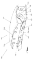
- FIG. 3 is an external perspective view of the airbag module 100 and shows a state in which the lid is closed.
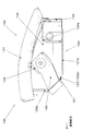
- FIG. 4 is a side view of the airbag module 100 and shows a state where the lid is closed.
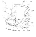
- FIG. 5 is an external perspective view of the airbag module 100 and shows a state where the lid is opened.
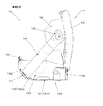
- FIG. 6 is a side view of the airbag module 100 and shows a state in which the lid is opened.
- FIG. 7 is a partial cross-sectional perspective view of the airbag module 100.
- the airbag module 100 includes a bag 110, a retainer 120, a lid 130, a webbing 140, an inflator (not shown), and the like. In FIGS. 3 to 7, the bag 110 and the inflator 220
- the bag 110 is formed into a bag shape by sewing or bonding a base fabric panel.
- the bag 110 is accommodated in the retainer 120 in a state of being folded into, for example, a roll shape or a bellows shape when not in use.
- an airbag control device (not shown) detects a collision by a sensor provided on the front fork 20 or the like, for example, the bag 110 is brought into a lid as shown in FIG. 1 by blowing inflating gas from the inflator. 130 is pushed open and expanded above the tank 60 to receive the upper body of the occupant and absorb the kinetic energy.
- FIG. 8 is a two-side view of the bag 110 after being expanded and inflated.
- FIG. 8 (a) is a side view seen from the left side
- FIG. 8 (b) is a view seen from the rear (FIG. 8 (a)).
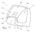
- FIG. 9 is a schematic external perspective view of the bag 110 after being expanded and inflated, as seen from the oblique front side.
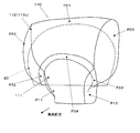
- FIG. 10 is a schematic external perspective view of the bag 110 after being expanded and inflated, and shows a state seen from the front side further than FIG. In FIG. 10, the shape of the windshield 83 of the cowling 80 is illustrated by a broken line for reference.
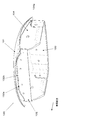
- FIG. 11 is a plan development view of a panel constituting the bag 110.
- the bag 110 includes a main gas chamber 111 and a sub gas chamber 112.
- the main gas chamber 111 is a main body of the bag 110 that expands and expands in the upper part of the tank 60.
- the rear portion of the main gas chamber 111 receives the driver's upper body during a collision and absorbs kinetic energy.
- the main gas chamber 111 is provided with a blowing port 111a into which a developing gas is directly blown from an inflator at the lower part.
- the main gas chamber 111 includes a main gas chamber main panel P11, a main gas chamber right side panel P12, a main gas chamber left side panel P13, and the like.
- the main gas chamber main panel P11 is formed in a band shape in which an inlet port 111a is formed at one end.
- the main gas chamber main panel P11 forms a lower surface portion, a front surface portion, an upper surface portion, and a rear surface portion of the main gas chamber 111 by joining one end portion and the other end portion into an annular shape. Further, in the main gas chamber main panel P11, portions corresponding to the front portion and the upper surface portion of the main gas chamber 111 are formed wider than the other portions in order to increase the width of the main gas chamber 111.
- the main gas chamber right side panel P ⁇ b> 12 and the main gas chamber left side panel P ⁇ b> 13 are parts constituting the right and left side portions of the main gas chamber 111.
- the outer peripheral edge portions of the main gas chamber right side panel P12 and the main gas chamber left side panel P13 are joined to the side end portion of the main gas chamber main panel P11 over the entire circumference.
- the auxiliary gas chamber 112 is provided in the vehicle front side region of the bag portion 100 and is disposed so as to cover from the front surface portion to the side surface portion of the main gas chamber 111.
- the auxiliary gas chamber 112 is formed by joining the auxiliary gas chamber main panel 112a to the main gas chamber 111 via the rib panel 112b.
- the auxiliary gas chamber main panel 112a is a part constituting the front portion and the side portion of the auxiliary gas chamber 112, and is disposed on the front surface of the main body of the bag 110 as shown in FIG. It overlaps the windshield 83 when viewed from the front. As shown in FIG.
- the sub gas chamber main panel 112a includes a sub gas chamber front panel P21, a sub gas chamber right side panel P22, and a sub gas chamber left side panel P23.
- the auxiliary gas chamber front panel P21 is a portion disposed on the front surface portion of the bag 110 after being expanded and inflated.
- the front end portions of the sub gas chamber right side panel P22 and the sub gas chamber left side panel P23 are joined to the right and left side end portions of the sub gas chamber front panel P21, respectively.
- the auxiliary gas chamber right side panel P22 and the auxiliary gas chamber left side panel P23 are portions disposed in front of the side surface of the bag 110 after being expanded and inflated.
- the front end portions of the auxiliary gas chamber right side panel P22 and the auxiliary gas chamber left side panel P23 are formed in an arc shape with a convex front side of the vehicle.
- the rib panel 112b is a strip-shaped panel disposed along the outer peripheral edge of the sub gas chamber main panel 112a.
- the rib panel 112 b is joined at both ends in the width direction to a panel constituting the outer peripheral edge portion of the sub gas chamber main panel 112 a and the surface portion of the main gas chamber 111.
- the rib panel 112b separates the sub-gas chamber main panel 112a from the surface of the main gas chamber 111 with a small amount of developing gas, thereby contributing to downsizing and the like by reducing the output of the inflator.
- the rib panel 112b includes a rib panel upper panel P31, a rib panel right side panel P32, a rib panel left side panel P33, and a rib panel lower panel P34.
- the rib panel upper panel P31 is a strip-shaped panel arranged along the vehicle width direction. One end of the rib panel upper panel P31 in the width direction is joined to the upper end of the sub gas chamber front panel P21 of the sub gas chamber main panel 112a. The other end of the rib panel upper panel P31 in the width direction is joined to the surface of the main gas chamber main panel P11 of the main gas chamber 111.
- the rib panel right side panel P32 and the rib panel left side panel P33 are substantially formed by the upper end portion, the rear end portion, and the lower end portion of the sub gas chamber right side panel P22 of the sub gas chamber main panel 112a and the sub gas chamber left side panel P23. It is a strip
- the outer end portions in the width direction of the rib panel right side panel P32 and the rib panel left side panel P33 are the upper end portion and the rear end portion of the sub gas chamber right side panel P22 and the sub gas chamber left side panel P23 of the sub gas chamber main panel 112a. , And joined to the lower end.
- inner ends in the width direction of the rib panel right side panel P32 and the rib panel left side panel P33 are joined to the surface of the main gas chamber main panel P11 of the main gas chamber 111.
- the rib panel lower panel P34 is a strip-like panel formed by curving into an arch shape having an upward projection along the lower end portion of the sub gas chamber front panel P21 of the sub gas chamber main panel 112a.
- One end portion in the width direction of the rib panel lower panel P34 is joined to the lower end portion of the sub gas chamber front panel P21 of the sub gas chamber main panel 112a.
- the other end of the rib panel lower panel P34 in the width direction is joined to the surface of the main gas chamber main panel P11 of the main gas chamber 111.
- An opening O for introducing a working gas is formed.
- the auxiliary gas chamber 112 expands and expands when a gas for expansion is supplied from the main gas chamber 111 through the opening O.
- the auxiliary gas chamber 112 is set such that the internal pressure during expansion and after expansion is lower than the internal pressure of the main gas chamber.
- reinforcing patch panels or the like that are provided so as to overlap with these panels can be appropriately provided in places where strength is required. Note that the above-described joining between the panels can be performed by, for example, stitching or bonding with a thread. Alternatively, a plurality of means may be used in combination.
- the retainer 120 is formed in a box shape having an upper portion opened by combining sheet metal members obtained by pressing a steel plate, for example.
- the bag 110 is fixed to the retainer 120 by a bag ring of an inflator (not shown) in a state where the air inlet 111a faces the lower surface of the retainer 120.
- the retainer 120 includes a lower surface portion 121, a front surface portion 122, a rear surface portion 123, a side surface portion 124, and the like.
- the lower surface portion 121 is a substantially flat plate portion that constitutes the bottom portion of the retainer 120. As shown in FIG. 7, an opening 121 a to which an inflator is attached is formed in the lower surface portion 121. In addition, a flange portion 121b protruding to the side of the retainer 120 is formed around the lower surface portion 121 in order to fasten the retainer 120 to the frame 10 of the vehicle body.
- the front surface portion 122 has a lower portion 122a that is a substantially flat slope formed by extending obliquely upward from the front end portion of the lower surface portion 121, and an upper portion 122b extending upward from the upper end portion of the lower portion 122a.
- the ends of the webbing 140 on the retainer 120 side are fixed to both ends of the lower portion 122a in the vehicle width direction.
- the front portion 132 of the lid 130 is fixed to the upper portion 122b.
- the rear surface portion 123 is a substantially flat portion that extends upward from the rear end portion of the lower surface portion 121.
- the side surface portion 124 is a substantially flat portion formed upwardly extending from the left and right end portions of the lower surface portion 121, and the front end portion and the rear end portion thereof are the front end portion 122 and the left and right end portions of the rear surface portion 123, respectively. It is joined with.
- the lid 130 is a lid-like member that closes the upper portion of the retainer 120 when not in use.
- the lid 130 rotates around a hinge disposed on the rear side of the vehicle.
- the bag 110 is opened to regulate the deployment direction of the bag 110.
- 12 and 13 are an external perspective view and a side view of a single component of the lid 130, respectively.
- FIG. 12 shows a state in which the lid 130 is viewed obliquely from the front side and obliquely from the lower side.
- the lid 130 includes an upper surface portion 131, a front surface portion 132, a rear surface portion 133, a side surface portion 134, and the like that are integrally formed of, for example, a resin material.
- the upper surface portion 131 is a surface portion that substantially closes the upper opening of the retainer 120 when not in use.
- the upper surface portion 131 is formed in a curved surface having a shape continuous with the outer surface of the tank 60, and functions as a design surface exposed to the outside of the vehicle.
- the front surface portion 132 is a substantially flat surface portion protruding downward from the front end portion of the upper surface portion 131.
- the front portion 132 is fixed to the upper portion 122b of the front portion 122 of the retainer 120 using, for example, a rivet.
- a tear line 132a is formed which extends substantially along the vehicle width direction and is formed in a groove shape smaller in thickness than the other portions.
- the tear line 132a is a fragile portion that is broken by a pressing force that the upper surface portion 131 receives from the bag 110 when the bag 110 is deployed and inflated.
- a long hole-like opening 132b that is long in the vehicle width direction is formed at the center of the tear line 132a.
- the opening 132a functions as a nucleus where the tear line 132a starts to break.
- the portion of the front surface portion 132 below the tear line 132a remains on the retainer 120 side, and only the portion above the tear line 132a rotates with the upper surface portion 131 and rises.
- the rear surface portion 133 is a substantially flat surface portion protruding downward from the rear end portion of the upper surface portion 131.
- the rear surface portion 133 is fixed to the rear surface portion 123 of the retainer 120 using, for example, rivets.
- a hinge portion (not shown) that is bent when the lid 130 is opened is formed on the upper portion of the rear surface portion 133 by reducing the wall thickness into a groove shape.
- the side surface portion 134 is a substantially flat surface portion protruding downward from the left and right end portions of the upper surface portion 131.
- a slit 134 a is formed in the side surface portion 134.
- the slit 134a extends upward from the lower end portion at the rear of the side surface portion 134, and is curved toward the rear surface portion 133 on the upper side thereof, and the upper end portion is disposed in the vicinity of the upper end portion and in the vicinity of the rear end portion of the side surface portion 134. Yes.
- a gap is formed between the front end portion of the side surface portion 134 and the side end portion of the front surface portion 132.
- the region in front of the slit 134a of the side surface portion 134 swings and rises together with the upper surface portion 131, and the region in the rear of the slit 134a remains on the retainer 120 side.
- a region behind the slit 134a of the side surface portion 134a is fixed to the side surface portion 124 of the retainer 120 by, for example, a resin fastener.
- the webbing 140 regulates the deployment direction of the bag 110 by regulating the swing of the lid 130 when the bag 110 is deployed and inflated.
- the webbing 140 is configured by providing a retainer-side metal fitting 141 and a lid-side metal fitting 142 at both ends of a main body configured in a belt shape.
- the retainer-side metal fitting 141 is fixed to the lower portion 122a of the front surface portion 122 of the retainer 120 by, for example, rivets.
- the lid-side metal fitting 142 is connected to a region in front of the slit 134 a in the side surface portion 134 of the lid 130 so as to be rotatable about an axis substantially orthogonal to the side surface portion 134.
- the inflator (not shown) generates a deployment gas that deploys and inflates the bag unit 100 when an airbag control device (not shown) detects a vehicle collision. For example, when the acceleration sensor provided in the front fork 20 detects a deceleration equal to or higher than a preset threshold value, the airbag control device determines a vehicle collision.
- the auxiliary gas chamber 112 expands and covers the front portion of the main gas chamber 111 so as to cover the front and sides of the front portion of the main gas chamber 111.
- the main gas chamber 111 can be effectively protected from the scattered matter even when the bag 110 protrudes from the windshield 83.
- the sub gas chamber main panel 112a of the sub gas chamber 112 is connected to the main gas chamber 111.
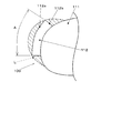
- FIG. 14 is a schematic cross-sectional view of the bag 110 showing the effects described above.
- 14 is, for example, a shape indicated by a broken line L in FIG. 14, and an extra developing gas is required for the increase in capacity corresponding to the hatched area in FIG.
- the technical scope of the present invention is not limited by the above-described embodiments, and can be changed as appropriate. Examples of such changes include the following, which are also within the technical scope of the present invention.
- the airbag device of the above-described embodiment is provided in a motorcycle as an example. However, the present invention is not limited to this, and can be applied to other types of saddle-ride type vehicles. .
- the shape, structure, material, manufacturing method, arrangement, and the like of each part constituting the airbag device are not limited to the above-described embodiment, and can be changed as appropriate.
- the bag is expanded and inflated after the vehicle collision is detected. However, the present invention is not limited to this, and the bag is expanded and inflated in response to detection of a vehicle crash sign (pre-crash). May be.
- Airbag Module 110 Bag 111 Main Gas Chamber 111a Blow Port 112 Sub-gas chamber 112a Sub-gas chamber main panel 112b Rib panel 120 Retainer 121 Lower surface 121a Open 121b Flange 122 Front surface 122a Lower 122b Upper 123 Rear surface 124 Side surface 130 Lid 131 Upper surface 132 Front surface 132a Tear line 13 2b Opening 133 Rear surface portion 134 Side surface portion 134a Slit 140 Webbing 141 Retainer side metal fitting 142 Lid side metal fitting P11 Main gas chamber main panel P12 Main gas chamber right side panel P13 Main gas chamber left side panel P21 Subgas chamber front panel P22 Subgas chamber Right side panel P23 Secondary gas chamber left side panel P31 Rib panel upper panel P32 Rib panel left side panel P33 Rib panel right side panel P34 Ri
Landscapes
- Engineering & Computer Science (AREA)
- Mechanical Engineering (AREA)
- Air Bags (AREA)
Abstract
展開状態におけるバッグ部の前面を飛散物から保護可能なエアバッグ装置を提供する。 車体フレーム(10)と、車体フレームの上方に配置されるとともに運転者が着座するシート(40)とを備える鞍乗り型車両(1)に設けられるエアバッグ装置100を、車両の衝突又は衝突の前兆の検出に応じて展開用ガスを発生するガス発生装置と、展開用ガスを吹き込まれることによってシート(40)の前方側で展開膨張するバッグ部(110)を有し、バッグ部は、運転者を受け止める主ガス室(111)と、主ガス室の前面部から側面部にかけて覆うように配置された副ガス室(112)とを備える構成とする。
Description
本発明は、例えば自動二輪車等の鞍乗り型車両に設けられ、衝突時等に搭乗者の前方で展開膨張するバッグ部を有するエアバッグ装置に関するものである。
運転者等の乗員が車体に跨って搭乗する自動二輪車等の鞍乗り型車両において、衝突時等に乗員の前方で展開膨張し、乗員の運動エネルギを吸収するバッグ部を有するエアバッグ装置を設けることが提案されている。
例えば、特許文献1には、車体フレームと、この車体フレームの上方に配置されるとともに、運転者が着座するシートと、車体フレームの上方かつシートの前方に配置されるとともに、所定値以上の減速度が車両に加わった際に展開するエアバッグを内部に有するエアバッグモジュールと、展開状態におけるエアバッグよりも前方に配置されるスクリーンとを備える自動二輪車が開示されている。
特許文献1に記載された構造によれば、展開状態におけるエアバッグの前面の大部分がスクリーンによって覆われるため、エアバッグを前方からの飛散物等から効果的に保護することができ、飛散物に対してエアバッグの損傷を防止することが可能である。
しかし、鞍乗り型車両のスクリーンの有無やサイズによっては、エアバッグの前面を保護することが難しい場合がある。
上述した問題に鑑み、本発明の課題は、展開状態におけるバッグ部の前面を飛散物から保護可能なエアバッグ装置を提供することである。
上述した問題に鑑み、本発明の課題は、展開状態におけるバッグ部の前面を飛散物から保護可能なエアバッグ装置を提供することである。
上記した課題を解決するため、本発明のエアバッグ装置は、車体フレームと、前記車体フレームの上方に配置されるとともに運転者が着座するシートとを備える鞍乗り型車両に設けられるエアバッグ装置であって、車両の衝突又は衝突の前兆の検出に応じて展開用ガスを発生するガス発生装置と、前記展開用ガスを吹き込まれることによって前記シートの前方側で展開膨張するバッグ部を有し、前記バッグ部は、前記運転者を受け止める主ガス室と、前記主ガス室の前面部から側面部にかけて覆うように配置された副ガス室とを備えることを特徴とする。
本発明によれば、バッグ部の展開時に、主ガス室の前部の前方及び側方を覆うように副ガス室が展開膨張して主ガス室の前部を覆うため、車両前方からの飛散物を副ガス室で受けることによって、主ガス室を飛散物から効果的に保護することができる。
本発明によれば、バッグ部の展開時に、主ガス室の前部の前方及び側方を覆うように副ガス室が展開膨張して主ガス室の前部を覆うため、車両前方からの飛散物を副ガス室で受けることによって、主ガス室を飛散物から効果的に保護することができる。
本発明において、前記副ガス室は、前方及び側方に面して配置された副ガス室メインパネルと、帯状に形成されるとともに、幅方向における一方の端部が前記副ガス室メインパネルの外周縁部に接合され、他方の端部が前記主ガス室の表面部に接合されたリブパネルとを有して構成される構成とすることができる。
これによれば、副ガス室メインパネルを、主ガス室の表面から所定の距離以上離間させて副ガス室の厚みを得るのに必要な展開用ガスの量を、このようなリブパネルを設けない場合に対して低減することができ、ガス発生装置の低出力化による小型化を図ることができる。
これによれば、副ガス室メインパネルを、主ガス室の表面から所定の距離以上離間させて副ガス室の厚みを得るのに必要な展開用ガスの量を、このようなリブパネルを設けない場合に対して低減することができ、ガス発生装置の低出力化による小型化を図ることができる。
以上説明したように、本発明によれば、展開状態におけるバッグ部の前面を飛散物から保護可能なエアバッグ装置を提供することができる。
以下、本発明を適用したエアバッグ装置の実施形態について説明する。
実施形態のエアバッグ装置は、例えば、鞍乗り型車両である自動二輪車に設けられ、衝突時等に搭乗者の前方側で展開膨張するバッグ部を備えている。
図1は、実施形態のエアバッグ装置を備えた自動二輪車の模式的側面図である。
図2は、図1の自動二輪車の模式的正面図である。
実施形態のエアバッグ装置は、例えば、鞍乗り型車両である自動二輪車に設けられ、衝突時等に搭乗者の前方側で展開膨張するバッグ部を備えている。
図1は、実施形態のエアバッグ装置を備えた自動二輪車の模式的側面図である。
図2は、図1の自動二輪車の模式的正面図である。
自動二輪車1は、前輪FW、後輪RW、フレーム10、フロントフォーク20、スイングアーム30、シート40、シートカウル50、タンク60、ハンドル70、カウリング80等を備えて構成されている。
フレーム10は、車体中央部に設けられる構造部材であって、その下部には図示しないエンジン、トランスミッション及び冷却装置、燃料供給装置などの補機類が搭載されている。
フロントフォーク20は、フレーム10の前端部に回動可能に取り付けられ、前輪FW及びフロントブレーキ等を支持する部材である。
フロントフォーク20は、内部にスプリング及びダンパが収容され伸縮するテレスコピック式のフロントサスペンションである。
フロントフォーク20における前輪FWの上部には、フロントフェンダ21が設けられている。
フロントフォーク20は、内部にスプリング及びダンパが収容され伸縮するテレスコピック式のフロントサスペンションである。
フロントフォーク20における前輪FWの上部には、フロントフェンダ21が設けられている。
スイングアーム30は、フレーム10の下部から後方に突き出して設けられ、フレーム10に対して揺動可能に取り付けられるとともに、後輪RWを支持する部材である。
スイングアーム30とフレーム10との間には、リアサスペンションの図示しないスプリングダンパユニットが設けられている。
スイングアーム30とフレーム10との間には、リアサスペンションの図示しないスプリングダンパユニットが設けられている。
シート40は、乗員が鞍乗りによって着座する部分であって、フレーム10の上部に設けられている。
シートカウル50は、シート40の後方でありかつ後輪RWの上方に配置された外装部材である。
タンク60は、シート40の前方側におけるフレーム10の上部に設けられ、燃料となるガソリンを貯留する容器である。
タンク60は、乗員の両肢の内股に挟まれる位置に設けられる。
なお、タンク60の上部における一部には、後述するエアバッグモジュール100が設けられる。
シートカウル50は、シート40の後方でありかつ後輪RWの上方に配置された外装部材である。
タンク60は、シート40の前方側におけるフレーム10の上部に設けられ、燃料となるガソリンを貯留する容器である。
タンク60は、乗員の両肢の内股に挟まれる位置に設けられる。
なお、タンク60の上部における一部には、後述するエアバッグモジュール100が設けられる。
ハンドル70は、フロントフォーク20の上部から車両後方側かつ車幅方向外側に突き出して形成され、乗員の手指により把持される操作部材である。
ハンドル70には、フロントブレーキレバー、クラッチレバー、各種灯火類のスイッチ等が設けられ、また、右側のグリップはスロットル操作部を兼ねている。
ハンドル70には、フロントブレーキレバー、クラッチレバー、各種灯火類のスイッチ等が設けられ、また、右側のグリップはスロットル操作部を兼ねている。
カウリング(フェアリング)80は、例えば樹脂系材料によって形成され、車体前部をカバーする外装部材である。
カウリング80は、フロントフォーク20の上部からフレーム10の前半部、エンジン等をカバーするフルカウリングである。
カウリング80は、フロントフォーク20の上部からフレーム10の前半部、エンジン等をカバーするフルカウリングである。
カウリング80は、ヘッドライト81、ミラー82、ウインドシールド83等を備えている。
ヘッドライト81は、カウリング80の前面部に設けられた照明装置である。
ミラー82は、カウリング80の左右上部に設けられた後方確認手段である。
ウインドシールド83は、カウリング80の前面部における上部に設けられた透明の部分であって、乗員の防風等に用いられるものである。
ヘッドライト81は、カウリング80の前面部に設けられた照明装置である。
ミラー82は、カウリング80の左右上部に設けられた後方確認手段である。
ウインドシールド83は、カウリング80の前面部における上部に設けられた透明の部分であって、乗員の防風等に用いられるものである。
図1に示すように、エアバッグモジュール100は、タンク60の上部に設けられている。エアバッグモジュール100は、自動二輪車1の衝突時等に、運転者の前方でバッグを展開膨張させ、運転者の上体を受け止めて運動エネルギを吸収するものである。
図3は、エアバッグモジュール100の外観斜視図であって、リッドが閉じた状態を示す図である。
図4は、エアバッグモジュール100の側面視図であって、リッドが閉じた状態を示す図である。
図5は、エアバッグモジュール100の外観斜視図であって、リッドが開いた状態を示す図である。
図6は、エアバッグモジュール100の側面視図であって、リッドが開いた状態を示す図である。
図7は、エアバッグモジュール100の部分断面斜視図である。
エアバッグモジュール100は、バッグ110、リテーナ120、リッド130、ウェビング140、及び、図示しないインフレータ等を備えて構成されている。
なお、図3乃至図7においては、バッグ110及びインフレータ220は図示を省略している。
図3は、エアバッグモジュール100の外観斜視図であって、リッドが閉じた状態を示す図である。
図4は、エアバッグモジュール100の側面視図であって、リッドが閉じた状態を示す図である。
図5は、エアバッグモジュール100の外観斜視図であって、リッドが開いた状態を示す図である。
図6は、エアバッグモジュール100の側面視図であって、リッドが開いた状態を示す図である。
図7は、エアバッグモジュール100の部分断面斜視図である。
エアバッグモジュール100は、バッグ110、リテーナ120、リッド130、ウェビング140、及び、図示しないインフレータ等を備えて構成されている。
なお、図3乃至図7においては、バッグ110及びインフレータ220は図示を省略している。
バッグ110は、基布パネルを縫合又は接着等することによって袋状に形成したものである。
バッグ110は、未使用時には例えばロール状、蛇腹状等に折り畳まれた状態でリテーナ120内に収容されている。
また、図示しないエアバッグ制御装置が、例えばフロントフォーク20等に設けたセンサによって衝突を検出した場合には、バッグ110は、インフレータから展開用ガスを吹き込まれることによって、図1に示すようにリッド130を押し開き、タンク60の上方で展開膨張して乗員の上体を受け止めて運動エネルギを吸収する。
バッグ110は、未使用時には例えばロール状、蛇腹状等に折り畳まれた状態でリテーナ120内に収容されている。
また、図示しないエアバッグ制御装置が、例えばフロントフォーク20等に設けたセンサによって衝突を検出した場合には、バッグ110は、インフレータから展開用ガスを吹き込まれることによって、図1に示すようにリッド130を押し開き、タンク60の上方で展開膨張して乗員の上体を受け止めて運動エネルギを吸収する。
図8は、展開膨張後のバッグ110の二面図であって、図8(a)は左側から見た側面図であり、図8(b)は後方から見た図(図8(a)のb-b部矢視図)である。
図9は、展開膨張後のバッグ110の模式的外観斜視図であって、斜め前方側から見た図である。
図10は、展開膨張後のバッグ110の模式的外観斜視図であって、図9よりもさらに前方側から見た状態を示す図である。
なお、図10には、参考のため、カウリング80のウインドシールド83の形状を破線により図示している。
図11は、バッグ110を構成するパネルの平面展開図である。
図9は、展開膨張後のバッグ110の模式的外観斜視図であって、斜め前方側から見た図である。
図10は、展開膨張後のバッグ110の模式的外観斜視図であって、図9よりもさらに前方側から見た状態を示す図である。
なお、図10には、参考のため、カウリング80のウインドシールド83の形状を破線により図示している。
図11は、バッグ110を構成するパネルの平面展開図である。
バッグ110は、主ガス室111、副ガス室112を備えている。
主ガス室111は、タンク60の上部で展開膨張するバッグ110の本体部である。
主ガス室111の後面部は、衝突時に運転者の上体を受け止めて運動エネルギを吸収する。
主ガス室111は、下部にインフレータから展開用ガスが直接吹き込まれる吹き込み口111aが設けられている。
主ガス室111は、タンク60の上部で展開膨張するバッグ110の本体部である。
主ガス室111の後面部は、衝突時に運転者の上体を受け止めて運動エネルギを吸収する。
主ガス室111は、下部にインフレータから展開用ガスが直接吹き込まれる吹き込み口111aが設けられている。
図11に示すように、主ガス室111は、主ガス室メインパネルP11、主ガス室右サイドパネルP12、主ガス室左サイドパネルP13等を有して構成されている。
主ガス室メインパネルP11は、一方の端部に吹き込み口111aが形成された帯状に形成されている。
主ガス室メインパネルP11は、一方の端部と他方の端部とを接合して環状にすることによって、主ガス室111の下面部、前面部、上面部、後面部を構成する。
また、主ガス室メインパネルP11において、主ガス室111の前面部及び上面部に相当する箇所は、主ガス室111の幅を広げるため、他の部分よりも幅広に形成されている。
主ガス室メインパネルP11は、一方の端部に吹き込み口111aが形成された帯状に形成されている。
主ガス室メインパネルP11は、一方の端部と他方の端部とを接合して環状にすることによって、主ガス室111の下面部、前面部、上面部、後面部を構成する。
また、主ガス室メインパネルP11において、主ガス室111の前面部及び上面部に相当する箇所は、主ガス室111の幅を広げるため、他の部分よりも幅広に形成されている。
主ガス室右サイドパネルP12及び主ガス室左サイドパネルP13は、主ガス室111の右側及び左側の側面部を構成する部分である。
主ガス室右サイドパネルP12及び主ガス室左サイドパネルP13の外周縁部は、全周にわたって主ガス室メインパネルP11の側端部と接合される。
主ガス室右サイドパネルP12及び主ガス室左サイドパネルP13の外周縁部は、全周にわたって主ガス室メインパネルP11の側端部と接合される。
副ガス室112は、バッグ部100の車両前方側の領域に設けられ、主ガス室111の前面部から側面部にかけて覆うように配置されている。
副ガス室112は、主ガス室111に、副ガス室メインパネル112aを、リブパネル112bを介して接合することによって形成されている。
副ガス室メインパネル112aは、副ガス室112の前面部及び側面部の主要部を構成する部分であって、図10に示すように、バッグ110の本体の前面に配置され、一部は車両前方視において、ウインドシールド83に重なっている。
図11に示すように、副ガス室メインパネル112aは、副ガス室フロントパネルP21、副ガス室右サイドパネルP22、副ガス室左サイドパネルP23を有して構成されている。
副ガス室フロントパネルP21は、展開膨張後におけるバッグ110の前面部に配置される部分である。
副ガス室右サイドパネルP22、副ガス室左サイドパネルP23の前端部は、副ガス室フロントパネルP21の右側、左側の側端部にそれぞれ接合されている。
副ガス室右サイドパネルP22、副ガス室左サイドパネルP23は、展開膨張後におけるバッグ110の側面部前方に配置される部分である。
副ガス室右サイドパネルP22、副ガス室左サイドパネルP23の前端部は、車両前方側が凸となる円弧状に形成されている。
副ガス室112は、主ガス室111に、副ガス室メインパネル112aを、リブパネル112bを介して接合することによって形成されている。
副ガス室メインパネル112aは、副ガス室112の前面部及び側面部の主要部を構成する部分であって、図10に示すように、バッグ110の本体の前面に配置され、一部は車両前方視において、ウインドシールド83に重なっている。
図11に示すように、副ガス室メインパネル112aは、副ガス室フロントパネルP21、副ガス室右サイドパネルP22、副ガス室左サイドパネルP23を有して構成されている。
副ガス室フロントパネルP21は、展開膨張後におけるバッグ110の前面部に配置される部分である。
副ガス室右サイドパネルP22、副ガス室左サイドパネルP23の前端部は、副ガス室フロントパネルP21の右側、左側の側端部にそれぞれ接合されている。
副ガス室右サイドパネルP22、副ガス室左サイドパネルP23は、展開膨張後におけるバッグ110の側面部前方に配置される部分である。
副ガス室右サイドパネルP22、副ガス室左サイドパネルP23の前端部は、車両前方側が凸となる円弧状に形成されている。
リブパネル112bは、副ガス室メインパネル112aの外周縁部に沿って配置された帯状のパネルである。
リブパネル112bは、その幅方向における両端部を、副ガス室メインパネル112aの外周縁部、及び、主ガス室111の表面部を構成するパネルに接合されている。
リブパネル112bは、少ない展開用ガスによって副ガス室メインパネル112aを主ガス室111の表面から離間させ、インフレータの低出力化による小型化等に寄与するものである。
リブパネル112bは、その幅方向における両端部を、副ガス室メインパネル112aの外周縁部、及び、主ガス室111の表面部を構成するパネルに接合されている。
リブパネル112bは、少ない展開用ガスによって副ガス室メインパネル112aを主ガス室111の表面から離間させ、インフレータの低出力化による小型化等に寄与するものである。
リブパネル112bは、リブパネルアッパパネルP31、リブパネル右サイドパネルP32、リブパネル左サイドパネルP33、リブパネルロワパネルP34を有して構成されている。
リブパネルアッパパネルP31は、車幅方向に沿って配置された帯状のパネルである。
リブパネルアッパパネルP31の幅方向における一方の端部は、副ガス室メインパネル112aの副ガス室フロントパネルP21の上端部に接合されている。
リブパネルアッパパネルP31の幅方向における他方の端部は、主ガス室111の主ガス室メインパネルP11の表面に接合されている。
リブパネルアッパパネルP31は、車幅方向に沿って配置された帯状のパネルである。
リブパネルアッパパネルP31の幅方向における一方の端部は、副ガス室メインパネル112aの副ガス室フロントパネルP21の上端部に接合されている。
リブパネルアッパパネルP31の幅方向における他方の端部は、主ガス室111の主ガス室メインパネルP11の表面に接合されている。
リブパネル右サイドパネルP32及びリブパネル左サイドパネルP33は、副ガス室メインパネル112aの副ガス室右サイドパネルP22、副ガス室左サイドパネルP23の上端部、後端部、下端部が形成するほぼJ字状の形状に沿って配置された帯状のパネルである。
リブパネル右サイドパネルP32及びリブパネル左サイドパネルP33の幅方向における外側の端部は、副ガス室メインパネル112aの副ガス室右サイドパネルP22、副ガス室左サイドパネルP23の上端部、後端部、下端部と接合されている。
一方、リブパネル右サイドパネルP32及びリブパネル左サイドパネルP33の幅方向における内側の端部は、主ガス室111の主ガス室メインパネルP11の表面に接合されている。
リブパネル右サイドパネルP32及びリブパネル左サイドパネルP33の幅方向における外側の端部は、副ガス室メインパネル112aの副ガス室右サイドパネルP22、副ガス室左サイドパネルP23の上端部、後端部、下端部と接合されている。
一方、リブパネル右サイドパネルP32及びリブパネル左サイドパネルP33の幅方向における内側の端部は、主ガス室111の主ガス室メインパネルP11の表面に接合されている。
リブパネルロワパネルP34は、副ガス室メインパネル112aの副ガス室フロントパネルP21の下端部に沿って、上方が凸となるアーチ状に湾曲して形成された帯状のパネルである。リブパネルロワパネルP34の幅方向における一方の端部は、副ガス室メインパネル112aの副ガス室フロントパネルP21の下端部に接合されている。
リブパネルロワパネルP34の幅方向における他方の端部は、主ガス室111の主ガス室メインパネルP11の表面に接合されている。
リブパネルロワパネルP34の幅方向における他方の端部は、主ガス室111の主ガス室メインパネルP11の表面に接合されている。
主ガス室111の主ガス室メインパネルP11の表面部であって、副ガス室112内に収容される領域には、副ガス室112と連通し、主ガス室111から副ガス室112へ展開用ガスを導入する開口Oが形成されている。
副ガス室112は、この開口Oを介して主ガス室111から展開用ガスを供給されることによって展開膨張する。副ガス室112は、展開膨張時及び膨張後の内圧が、主ガス室の内圧に対し低くなるように設定されている。
また、強度が必要な箇所には、上述したパネル以外に、これらのパネルと重ね合わせて設けられる補強用のパッチパネル等を適宜設けることが可能である。なお、上述した各パネル間の接合は、例えば糸による縫合や接着等によって行なうことが可能である。あるいは複数の手段を併用してもよい。
副ガス室112は、この開口Oを介して主ガス室111から展開用ガスを供給されることによって展開膨張する。副ガス室112は、展開膨張時及び膨張後の内圧が、主ガス室の内圧に対し低くなるように設定されている。
また、強度が必要な箇所には、上述したパネル以外に、これらのパネルと重ね合わせて設けられる補強用のパッチパネル等を適宜設けることが可能である。なお、上述した各パネル間の接合は、例えば糸による縫合や接着等によって行なうことが可能である。あるいは複数の手段を併用してもよい。
リテーナ120は、例えば鋼板をプレス加工した板金部材を組み合わせることによって上部が開口したボックス状に形成されている。
バッグ110は、吹込み口111aがリテーナ120の下面と対向した状態で、図示しないインフレータのバッグリングによってリテーナ120に固定される。
リテーナ120は、下面部121、前面部122、後面部123、側面部124等を備えて構成されている。
バッグ110は、吹込み口111aがリテーナ120の下面と対向した状態で、図示しないインフレータのバッグリングによってリテーナ120に固定される。
リテーナ120は、下面部121、前面部122、後面部123、側面部124等を備えて構成されている。
下面部121は、リテーナ120の底部を構成するほぼ平板状の部分である。
下面部121には、図7に示すように、インフレータが取り付けられる開口121aが形成されている。
また、下面部121の周囲には、リテーナ120を車体のフレーム10等に締結するため、リテーナ120の側方へ突き出したフランジ部121bが形成されている。
下面部121には、図7に示すように、インフレータが取り付けられる開口121aが形成されている。
また、下面部121の周囲には、リテーナ120を車体のフレーム10等に締結するため、リテーナ120の側方へ突き出したフランジ部121bが形成されている。
前面部122は、下面部121の前端部から斜め上方へ延びて形成されたほぼ平板状の斜面である下部122aと、下部122aの上端部から上方へ延びた上部122bとを有している。
下部122aの車幅方向における両端部には、ウェビング140のリテーナ120側の端部が固定される。
また、上部122bには、リッド130の前面部132が固定される。
後面部123は、下面部121の後端部から上方へ延びて形成されたほぼ平板状の部分である。
側面部124は、下面部121の左右両端部から上方へ延びて形成されたほぼ平板状の部分であって、その前端部及び後端部は、それぞれ前面部122、後面部123の左右両端部と接合されている。
下部122aの車幅方向における両端部には、ウェビング140のリテーナ120側の端部が固定される。
また、上部122bには、リッド130の前面部132が固定される。
後面部123は、下面部121の後端部から上方へ延びて形成されたほぼ平板状の部分である。
側面部124は、下面部121の左右両端部から上方へ延びて形成されたほぼ平板状の部分であって、その前端部及び後端部は、それぞれ前面部122、後面部123の左右両端部と接合されている。
リッド130は、未使用時においてはリテーナ120の上部を閉塞する蓋状の部材であって、バッグ110の展開膨張時には、図1に示すように、車両後方側に配置されたヒンジ回りに回動して開き、バッグ110の展開方向を規制するものである。
図12、図13は、それぞれリッド130の部品単体の外観斜視図及び側面視図である。
図12は、リッド130を斜め前方側かつ斜め下方側から見た状態を示している。
リッド130は、例えば樹脂系材料によって一体に形成された上面部131、前面部132、後面部133、側面部134等を有して構成されている。
図12、図13は、それぞれリッド130の部品単体の外観斜視図及び側面視図である。
図12は、リッド130を斜め前方側かつ斜め下方側から見た状態を示している。
リッド130は、例えば樹脂系材料によって一体に形成された上面部131、前面部132、後面部133、側面部134等を有して構成されている。
上面部131は、未使用時にリテーナ120の上部開口を実質的に閉塞する面部である。
上面部131は、タンク60の外表面と連続した形状を有する曲面状に形成され、車両の外部に露出する意匠面として機能する。
上面部131は、タンク60の外表面と連続した形状を有する曲面状に形成され、車両の外部に露出する意匠面として機能する。
前面部132は、上面部131の前端部から下方へ突き出したほぼ平板状の面部である。
前面部132は、リテーナ120の前面部122における上部122bに、例えばリベットを用いて固定される。
前面部132の上端部近傍には、車幅方向にほぼ沿って伸びるとともに、他の部分よりも溝状に肉厚を小さく形成されたテアライン132aが形成されている。
このテアライン132aは、バッグ110の展開膨張時に、バッグ110から上面部131が受ける押圧力によって破断する脆弱部である。
テアライン132aの中央部には、車幅方向に長い長孔状の開口132bが形成されている。この開口132aは、テアライン132aが破断を開始する核として機能する。
リッド130の開放時には、前面部132におけるテアライン132aよりも下方の部分は、リテーナ120側に残り、テアライン132aよりも上方の部分のみが上面部131とともに回動し上昇する。
前面部132は、リテーナ120の前面部122における上部122bに、例えばリベットを用いて固定される。
前面部132の上端部近傍には、車幅方向にほぼ沿って伸びるとともに、他の部分よりも溝状に肉厚を小さく形成されたテアライン132aが形成されている。
このテアライン132aは、バッグ110の展開膨張時に、バッグ110から上面部131が受ける押圧力によって破断する脆弱部である。
テアライン132aの中央部には、車幅方向に長い長孔状の開口132bが形成されている。この開口132aは、テアライン132aが破断を開始する核として機能する。
リッド130の開放時には、前面部132におけるテアライン132aよりも下方の部分は、リテーナ120側に残り、テアライン132aよりも上方の部分のみが上面部131とともに回動し上昇する。
後面部133は、上面部131の後端部から下方へ突き出したほぼ平板状の面部である。
後面部133は、リテーナ120の後面部123に、例えばリベットを用いて固定される。
後面部133の上部には、肉厚を溝状に小さくすることによって、リッド130の開放時に屈曲する図示しないヒンジ部が形成されている。
後面部133は、リテーナ120の後面部123に、例えばリベットを用いて固定される。
後面部133の上部には、肉厚を溝状に小さくすることによって、リッド130の開放時に屈曲する図示しないヒンジ部が形成されている。
側面部134は、上面部131の左右側端部から下方へ突き出したほぼ平板状の面部である。
側面部134には、スリット134aが形成されている。
スリット134aは、側面部134の後方における下端部から上方へ延び、その上方側において後面部133側へカーブしており、上端部は側面部134における上端部近傍かつ後端部近傍に配置されている。
側面部134の前端部と前面部132の側端部との間には、隙間が形成されている。
リッド130の開放時には、側面部134のスリット134aよりも前方の領域は上面部131とともに揺動して上昇し、スリット134aよりも後方の領域はリテーナ120側に残るようになっている。この側面部134aのスリット134aよりも後方の領域は、例えば樹脂製のファスナ等によってリテーナ120の側面部124に固定されている。
側面部134には、スリット134aが形成されている。
スリット134aは、側面部134の後方における下端部から上方へ延び、その上方側において後面部133側へカーブしており、上端部は側面部134における上端部近傍かつ後端部近傍に配置されている。
側面部134の前端部と前面部132の側端部との間には、隙間が形成されている。
リッド130の開放時には、側面部134のスリット134aよりも前方の領域は上面部131とともに揺動して上昇し、スリット134aよりも後方の領域はリテーナ120側に残るようになっている。この側面部134aのスリット134aよりも後方の領域は、例えば樹脂製のファスナ等によってリテーナ120の側面部124に固定されている。
ウェビング140は、バッグ110の展開膨張時に、リッド130の揺動を規制してバッグ110の展開方向を規制するものである。
ウェビング140は、ベルト状に構成された本体部の両端部に、リテーナ側金具141、リッド側金具142を設けて構成されている。
リテーナ側金具141は、リテーナ120の前面部122における下部122aに、例えばリベット等によって固定されている。
リッド側金具142は、リッド130の側面部134におけるスリット134aよりも前方側の領域に、側面部134と実質的に直交する軸回りに回動可能に接続されている。
ウェビング140は、ベルト状に構成された本体部の両端部に、リテーナ側金具141、リッド側金具142を設けて構成されている。
リテーナ側金具141は、リテーナ120の前面部122における下部122aに、例えばリベット等によって固定されている。
リッド側金具142は、リッド130の側面部134におけるスリット134aよりも前方側の領域に、側面部134と実質的に直交する軸回りに回動可能に接続されている。
図示しないインフレータは、図示しないエアバッグ制御装置が、車両の衝突を検出した場合に、バッグ部100を展開膨張させる展開用ガスを発生するものである。
エアバッグ制御装置は、例えば、フロントフォーク20に設けられた加速度センサが、予め設定された閾値以上の減速度を検出した場合に、車両の衝突を判定する。
エアバッグ制御装置は、例えば、フロントフォーク20に設けられた加速度センサが、予め設定された閾値以上の減速度を検出した場合に、車両の衝突を判定する。
以上説明した本実施形態によれば、以下の効果を得ることができる。
(1)バッグ110の展開時に、主ガス室111の前部の前方及び側方を覆うように副ガス室112が展開膨張して主ガス室111の前部を覆うため、車両前方からの飛散物を副ガス室112で受けることによって、バッグ110がウインドシールド83から張り出す場合であっても、主ガス室111を飛散物から効果的に保護することができる。
(2)副ガス室112の副ガス室メインパネル112aを帯状のリブパネル112bを介して主ガス室111に接続することによって、副ガス室112の副ガス室メインパネル112aを、主ガス室111の表面から所定の距離以上離間させて副ガス室112の厚みを得るのに必要な展開用ガスの量を、このようなリブパネル112bを設けない場合に対して低減することができ、インフレータの低出力化による小型化を図ることができる。
図14は、上述した効果を示すバッグ110の模式的断面図である。
図14に示す領域Aにおいて、仮にリブパネルを設けずに、主ガス室111に直接接合されるメインパネルのみで本実施形態と同等以上の副ガス室の厚さを確保しようとした場合、メインパネルの断面形状は例えば図14に破線Lで示す形状になり、図14において斜線を付した領域に相当する容量増加の分だけ展開用ガスが余分に必要となる。
(1)バッグ110の展開時に、主ガス室111の前部の前方及び側方を覆うように副ガス室112が展開膨張して主ガス室111の前部を覆うため、車両前方からの飛散物を副ガス室112で受けることによって、バッグ110がウインドシールド83から張り出す場合であっても、主ガス室111を飛散物から効果的に保護することができる。
(2)副ガス室112の副ガス室メインパネル112aを帯状のリブパネル112bを介して主ガス室111に接続することによって、副ガス室112の副ガス室メインパネル112aを、主ガス室111の表面から所定の距離以上離間させて副ガス室112の厚みを得るのに必要な展開用ガスの量を、このようなリブパネル112bを設けない場合に対して低減することができ、インフレータの低出力化による小型化を図ることができる。
図14は、上述した効果を示すバッグ110の模式的断面図である。
図14に示す領域Aにおいて、仮にリブパネルを設けずに、主ガス室111に直接接合されるメインパネルのみで本実施形態と同等以上の副ガス室の厚さを確保しようとした場合、メインパネルの断面形状は例えば図14に破線Lで示す形状になり、図14において斜線を付した領域に相当する容量増加の分だけ展開用ガスが余分に必要となる。
なお、本発明の技術的範囲は、上述した各実施形態によって限定されるものではなく、適宜変更することが可能である。このような変更の一例として例えば以下のようなものがあり、これらも本発明の技術的範囲内である。
(1)上述した実施形態のエアバッグ装置は、一例として自動二輪車に設けられるものであったが、本発明はこれに限らず、他種の鞍乗り型車両にも適用することが可能である。(2)エアバッグ装置を構成する各部分の形状、構造、材質、製法、配置等は、上述した実施形態に限定されず、適宜変更することが可能である。
(3)上述した実施形態においては、車両の衝突検出後にバッグを展開膨張させているが、これに限らず、車両の衝突の前兆(プリクラッシュ)の検出に応じてバッグを展開膨張させるようにしてもよい。
(1)上述した実施形態のエアバッグ装置は、一例として自動二輪車に設けられるものであったが、本発明はこれに限らず、他種の鞍乗り型車両にも適用することが可能である。(2)エアバッグ装置を構成する各部分の形状、構造、材質、製法、配置等は、上述した実施形態に限定されず、適宜変更することが可能である。
(3)上述した実施形態においては、車両の衝突検出後にバッグを展開膨張させているが、これに限らず、車両の衝突の前兆(プリクラッシュ)の検出に応じてバッグを展開膨張させるようにしてもよい。
1 自動二輪車 FW 前輪
RW 後輪 10 フレーム
20 フロントフォーク 21 フロントフェンダ
30 スイングアーム 40 シート
50 シートカウル 60 タンク
70 ハンドル 80 カウリング
81 ヘッドライト 82 ミラー
83 ウインドシールド
100 エアバッグモジュール 110 バッグ
111 主ガス室 111a 吹き込み口
112 副ガス室 112a 副ガス室メインパネル
112b リブパネル 120 リテーナ
121 下面部 121a 開口
121b フランジ部 122 前面部
122a 下部 122b 上部
123 後面部 124 側面部
130 リッド 131 上面部
132 前面部 132a テアライン
132b 開口 133 後面部
134 側面部 134a スリット
140 ウェビング 141 リテーナ側金具
142 リッド側金具
P11 主ガス室メインパネル P12 主ガス室右サイドパネル
P13 主ガス室左サイドパネル P21 副ガス室フロントパネル
P22 副ガス室右サイドパネル P23 副ガス室左サイドパネル
P31 リブパネルアッパパネル P32 リブパネル左サイドパネル
P33 リブパネル右サイドパネル P34 リブパネルロワパネル
RW 後輪 10 フレーム
20 フロントフォーク 21 フロントフェンダ
30 スイングアーム 40 シート
50 シートカウル 60 タンク
70 ハンドル 80 カウリング
81 ヘッドライト 82 ミラー
83 ウインドシールド
100 エアバッグモジュール 110 バッグ
111 主ガス室 111a 吹き込み口
112 副ガス室 112a 副ガス室メインパネル
112b リブパネル 120 リテーナ
121 下面部 121a 開口
121b フランジ部 122 前面部
122a 下部 122b 上部
123 後面部 124 側面部
130 リッド 131 上面部
132 前面部 132a テアライン
132b 開口 133 後面部
134 側面部 134a スリット
140 ウェビング 141 リテーナ側金具
142 リッド側金具
P11 主ガス室メインパネル P12 主ガス室右サイドパネル
P13 主ガス室左サイドパネル P21 副ガス室フロントパネル
P22 副ガス室右サイドパネル P23 副ガス室左サイドパネル
P31 リブパネルアッパパネル P32 リブパネル左サイドパネル
P33 リブパネル右サイドパネル P34 リブパネルロワパネル
Claims (2)
- 車体フレームと、前記車体フレームの上方に配置されるとともに運転者が着座するシートとを備える鞍乗り型車両に設けられるエアバッグ装置であって、
車両の衝突又は衝突の前兆の検出に応じて展開用ガスを発生するガス発生装置と、
前記展開用ガスを吹き込まれることによって前記シートの前方側で展開膨張するバッグ部を有し、
前記バッグ部は、前記運転者を受け止める主ガス室と、前記主ガス室の前面部から側面部にかけて覆うように配置された副ガス室とを備えること
を特徴とするエアバッグ装置。 - 前記副ガス室は、前方及び側方に面して配置された副ガス室メインパネルと、
帯状に形成されるとともに、幅方向における一方の端部が前記副ガス室メインパネルの外周縁部に接合され、他方の端部が前記主ガス室の表面部に接合されたリブパネルと
を有して構成されることを特徴とする請求項1に記載のエアバッグ装置。
Applications Claiming Priority (2)
| Application Number | Priority Date | Filing Date | Title |
|---|---|---|---|
| JP2011-077458 | 2011-03-31 | ||
| JP2011077458A JP2012210866A (ja) | 2011-03-31 | 2011-03-31 | エアバッグ装置 |
Publications (1)
| Publication Number | Publication Date |
|---|---|
| WO2012132159A1 true WO2012132159A1 (ja) | 2012-10-04 |
Family
ID=46929956
Family Applications (1)
| Application Number | Title | Priority Date | Filing Date |
|---|---|---|---|
| PCT/JP2011/080257 Ceased WO2012132159A1 (ja) | 2011-03-31 | 2011-12-27 | エアバッグ装置 |
Country Status (2)
| Country | Link |
|---|---|
| JP (1) | JP2012210866A (ja) |
| WO (1) | WO2012132159A1 (ja) |
Cited By (1)
| Publication number | Priority date | Publication date | Assignee | Title |
|---|---|---|---|---|
| WO2019188418A1 (ja) * | 2018-03-29 | 2019-10-03 | 本田技研工業株式会社 | 鞍乗型車両 |
Citations (4)
| Publication number | Priority date | Publication date | Assignee | Title |
|---|---|---|---|---|
| JP2003291875A (ja) * | 2002-04-05 | 2003-10-15 | Honda Motor Co Ltd | 小型車両用エアバッグ装置 |
| JP2010228677A (ja) * | 2009-03-27 | 2010-10-14 | Honda Motor Co Ltd | 二輪車用エアバック装置 |
| JP2011073557A (ja) * | 2009-09-30 | 2011-04-14 | Honda Motor Co Ltd | 鞍乗り型車両のエアバッグ装置 |
| JP2011073560A (ja) * | 2009-09-30 | 2011-04-14 | Honda Motor Co Ltd | 鞍乗り型車両のエアバッグ装置 |
-
2011
- 2011-03-31 JP JP2011077458A patent/JP2012210866A/ja not_active Withdrawn
- 2011-12-27 WO PCT/JP2011/080257 patent/WO2012132159A1/ja not_active Ceased
Patent Citations (4)
| Publication number | Priority date | Publication date | Assignee | Title |
|---|---|---|---|---|
| JP2003291875A (ja) * | 2002-04-05 | 2003-10-15 | Honda Motor Co Ltd | 小型車両用エアバッグ装置 |
| JP2010228677A (ja) * | 2009-03-27 | 2010-10-14 | Honda Motor Co Ltd | 二輪車用エアバック装置 |
| JP2011073557A (ja) * | 2009-09-30 | 2011-04-14 | Honda Motor Co Ltd | 鞍乗り型車両のエアバッグ装置 |
| JP2011073560A (ja) * | 2009-09-30 | 2011-04-14 | Honda Motor Co Ltd | 鞍乗り型車両のエアバッグ装置 |
Cited By (2)
| Publication number | Priority date | Publication date | Assignee | Title |
|---|---|---|---|---|
| WO2019188418A1 (ja) * | 2018-03-29 | 2019-10-03 | 本田技研工業株式会社 | 鞍乗型車両 |
| JPWO2019188418A1 (ja) * | 2018-03-29 | 2021-03-11 | 本田技研工業株式会社 | 鞍乗型車両 |
Also Published As
| Publication number | Publication date |
|---|---|
| JP2012210866A (ja) | 2012-11-01 |
Similar Documents
| Publication | Publication Date | Title |
|---|---|---|
| US6474686B1 (en) | Air bag device | |
| JP3685873B2 (ja) | 自動二輪車用エアバッグ装置 | |
| US20120074677A1 (en) | Airbag, airbag device, and method for sewing lid member of airbag | |
| JP4226259B2 (ja) | 小型車両用エアバッグ装置 | |
| US20170217397A1 (en) | Airbag Apparatus | |
| WO2010050019A1 (ja) | 車両用ニーエアバッグ装置 | |
| US7988189B2 (en) | Air bag cover and air bag device | |
| US8100431B2 (en) | Front passenger seat airbag apparatus | |
| JP5604353B2 (ja) | エアバッグ装置及びエアバッグカバー | |
| EP1817211A1 (en) | Separate reaction surface for vehicle trim panel | |
| CN100354160C (zh) | 气囊装置和带气囊装置的摩托车 | |
| WO2012132159A1 (ja) | エアバッグ装置 | |
| EP3511209B1 (en) | Vehicle air bag apparatus | |
| US7213831B2 (en) | Handle cover, motorbike | |
| JP2008143301A (ja) | 歩行者保護用フードエアバッグ装置 | |
| EP2692591B1 (en) | Air bag device | |
| JP2007030786A (ja) | ロールオーバ保護装置 | |
| JP5767992B2 (ja) | エアバッグ装置 | |
| JPH0642925Y2 (ja) | 乗員拘束用エアバッグ装置 | |
| JP5408081B2 (ja) | 助手席用エアバッグ装置 | |
| WO2025248716A1 (ja) | 助手席エアバッグのリッド構造 | |
| JP5628561B2 (ja) | 自動車の助手席用エアバッグ装置 | |
| JP5396091B2 (ja) | 助手席用エアバッグ装置 | |
| KR101392615B1 (ko) | 자동차용 에어백 케이스의 표면 형상구조 |
Legal Events
| Date | Code | Title | Description |
|---|---|---|---|
| 121 | Ep: the epo has been informed by wipo that ep was designated in this application |
Ref document number: 11862735 Country of ref document: EP Kind code of ref document: A1 |
|
| DPE1 | Request for preliminary examination filed after expiration of 19th month from priority date (pct application filed from 20040101) | ||
| NENP | Non-entry into the national phase |
Ref country code: DE |
|
| 122 | Ep: pct application non-entry in european phase |
Ref document number: 11862735 Country of ref document: EP Kind code of ref document: A1 |