WO2012131981A1 - 情報処理装置、プリンタ設定方法及びプリンタ設定プログラム - Google Patents
情報処理装置、プリンタ設定方法及びプリンタ設定プログラム Download PDFInfo
- Publication number
- WO2012131981A1 WO2012131981A1 PCT/JP2011/058225 JP2011058225W WO2012131981A1 WO 2012131981 A1 WO2012131981 A1 WO 2012131981A1 JP 2011058225 W JP2011058225 W JP 2011058225W WO 2012131981 A1 WO2012131981 A1 WO 2012131981A1
- Authority
- WO
- WIPO (PCT)
- Prior art keywords
- information
- printer
- setting
- client
- processing apparatus
- Prior art date
- Legal status (The legal status is an assumption and is not a legal conclusion. Google has not performed a legal analysis and makes no representation as to the accuracy of the status listed.)
- Ceased
Links
Images















Classifications
-
- G—PHYSICS
- G06—COMPUTING OR CALCULATING; COUNTING
- G06F—ELECTRIC DIGITAL DATA PROCESSING
- G06F3/00—Input arrangements for transferring data to be processed into a form capable of being handled by the computer; Output arrangements for transferring data from processing unit to output unit, e.g. interface arrangements
- G06F3/12—Digital output to print unit, e.g. line printer, chain printer
- G06F3/1201—Dedicated interfaces to print systems
- G06F3/1223—Dedicated interfaces to print systems specifically adapted to use a particular technique
- G06F3/1229—Printer resources management or printer maintenance, e.g. device status, power levels
- G06F3/1231—Device related settings, e.g. IP address, Name, Identification
-
- G—PHYSICS
- G06—COMPUTING OR CALCULATING; COUNTING
- G06F—ELECTRIC DIGITAL DATA PROCESSING
- G06F3/00—Input arrangements for transferring data to be processed into a form capable of being handled by the computer; Output arrangements for transferring data from processing unit to output unit, e.g. interface arrangements
- G06F3/12—Digital output to print unit, e.g. line printer, chain printer
- G06F3/1201—Dedicated interfaces to print systems
- G06F3/1202—Dedicated interfaces to print systems specifically adapted to achieve a particular effect
- G06F3/1203—Improving or facilitating administration, e.g. print management
- G06F3/1204—Improving or facilitating administration, e.g. print management resulting in reduced user or operator actions, e.g. presetting, automatic actions, using hardware token storing data
-
- G—PHYSICS
- G06—COMPUTING OR CALCULATING; COUNTING
- G06F—ELECTRIC DIGITAL DATA PROCESSING
- G06F3/00—Input arrangements for transferring data to be processed into a form capable of being handled by the computer; Output arrangements for transferring data from processing unit to output unit, e.g. interface arrangements
- G06F3/12—Digital output to print unit, e.g. line printer, chain printer
- G06F3/1201—Dedicated interfaces to print systems
- G06F3/1223—Dedicated interfaces to print systems specifically adapted to use a particular technique
- G06F3/1224—Client or server resources management
- G06F3/1225—Software update, e.g. print driver, modules, plug-ins, fonts
-
- G—PHYSICS
- G06—COMPUTING OR CALCULATING; COUNTING
- G06F—ELECTRIC DIGITAL DATA PROCESSING
- G06F3/00—Input arrangements for transferring data to be processed into a form capable of being handled by the computer; Output arrangements for transferring data from processing unit to output unit, e.g. interface arrangements
- G06F3/12—Digital output to print unit, e.g. line printer, chain printer
- G06F3/1201—Dedicated interfaces to print systems
- G06F3/1223—Dedicated interfaces to print systems specifically adapted to use a particular technique
- G06F3/1229—Printer resources management or printer maintenance, e.g. device status, power levels
- G06F3/1232—Transmitting printer device capabilities, e.g. upon request or periodically
-
- G—PHYSICS
- G06—COMPUTING OR CALCULATING; COUNTING
- G06F—ELECTRIC DIGITAL DATA PROCESSING
- G06F3/00—Input arrangements for transferring data to be processed into a form capable of being handled by the computer; Output arrangements for transferring data from processing unit to output unit, e.g. interface arrangements
- G06F3/12—Digital output to print unit, e.g. line printer, chain printer
- G06F3/1201—Dedicated interfaces to print systems
- G06F3/1278—Dedicated interfaces to print systems specifically adapted to adopt a particular infrastructure
- G06F3/1285—Remote printer device, e.g. being remote from client or server
-
- G—PHYSICS
- G06—COMPUTING OR CALCULATING; COUNTING
- G06F—ELECTRIC DIGITAL DATA PROCESSING
- G06F3/00—Input arrangements for transferring data to be processed into a form capable of being handled by the computer; Output arrangements for transferring data from processing unit to output unit, e.g. interface arrangements
- G06F3/12—Digital output to print unit, e.g. line printer, chain printer
- G06F3/1201—Dedicated interfaces to print systems
- G06F3/1202—Dedicated interfaces to print systems specifically adapted to achieve a particular effect
- G06F3/1218—Reducing or saving of used resources, e.g. avoiding waste of consumables or improving usage of hardware resources
- G06F3/122—Reducing or saving of used resources, e.g. avoiding waste of consumables or improving usage of hardware resources with regard to computing resources, e.g. memory, CPU
-
- G—PHYSICS
- G06—COMPUTING OR CALCULATING; COUNTING
- G06F—ELECTRIC DIGITAL DATA PROCESSING
- G06F9/00—Arrangements for program control, e.g. control units
- G06F9/06—Arrangements for program control, e.g. control units using stored programs, i.e. using an internal store of processing equipment to receive or retain programs
- G06F9/44—Arrangements for executing specific programs
- G06F9/4401—Bootstrapping
- G06F9/4411—Configuring for operating with peripheral devices; Loading of device drivers
Definitions
- the present invention relates to an information processing apparatus that automatically sets a printing environment of an image forming apparatus, a printer setting method, and a printer setting program.
- the printing apparatus has the printing apparatus information as a database, the printing instruction apparatus acquires the printing apparatus information from the database, and automatically sets the installed functions of the printing apparatus when registering the printer driver. There is.
- each PC is in the same environment at the time of initial introduction.
- it will be managed by each person, so it is necessary to apply various Windows (registered trademark) patches and application It was necessary to manage updates etc. on each PC, and there was a problem in operation.
- FIG. 1 is a diagram illustrating an example of a server-based virtualization technology.
- the server-based type uses a Windows (registered trademark) server OS (Operating System) desktop as a screen transfer protocol (for example, ICA: Independent Computing). This is a method of transferring a screen to a local terminal via Architecture.
- Windows (registered trademark) server OS include Windows (registered trademark) Server 2008 R2.
- ICA is a communication protocol unique to Citrix (registered trademark) used when an application on the Citrix Presentation Server is used.
- This method does not require customization for each user, and a standardized standard desktop is provided to each user.
- the ability to support up to hundreds of users on a single server offers cost savings over any other virtual desktop technology.
- a third print attribute is generated based on the first print attribute associated with the virtual printer on the server and the second print attribute requested by the client, and the print request is made based on the third print attribute.
- mapping printer that maps a printer driver defined in the client PC to the server side is generally used.
- mapping printer reflects only basic setting information of the printer set in the client PC in the Windows (registered trademark) server OS, there is a technique for reflecting various setting information of the printer driver of the client PC on the server side. .
- This technology is an excellent method for reflecting the printer driver settings defined in the client PC to the server.
- each client PC remains in the conventional Windows (registered trademark) environment, and it is necessary to install and set a printer driver for each PC.
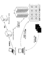
- FIG. 2 is a diagram illustrating an example of a virtual PC type virtualization technology.
- the Windows (registered trademark) client OS desktop installed on the virtual machine is transferred to the local terminal via a screen transfer protocol (for example, Citrix (registered trademark) ICA). It is a method to do.
- This virtual PC type is suitable when a desktop customized for each user is required.
- VDI virtual desktop infrastructure
- This VDI type is highly cost effective because multiple virtual desktops can be executed on the server, but it is assumed that the server and each client are always connected via the network. There are many challenges.
- XenServer is Xen-based virtualization software provided by Citrix Systems (hereinafter, “Citrix”), and adds various management functions necessary for enterprise environments to Xen.
- V Shehr relies on virtualization capabilities to transform the data center into a greatly simplified cloud computing infrastructure.
- VMware vSphere it is possible to construct a cloud computing IT infrastructure by using virtualization to reduce capital investment and operation costs.
- Hyper-V is a hypervisor-based virtualization system for x64 provided by MicroSoft (registered trademark), and realizes a plurality of virtual machines with one computer (server).
- (3) Local Virtual PC Type FIG. 3 is a diagram illustrating an example of a local virtual PC type virtualization technology.
- the local virtual PC type is a technology that has been practically used relatively recently. As shown in FIG. 3, the local virtual PC type is a method of starting a virtual machine on virtual software of a local PC and using an OS desktop installed in the virtual machine. Unlike the two virtualization technologies (1) and (2) described above, it can be used offline.
- This local virtual PC type is assumed to be used as an approach for sales employees who often go out, etc., or as an approach to have a personal and company desktop on one local PC.
- the image of the virtual machine is centrally managed by the center server, and for example, a required virtual machine can be provided in response to a request from a local PC (also referred to as a client PC) in which XenClient is installed.
- a local PC also referred to as a client PC
- XenClient XenClient
- XenClient is virtualization software that uses a hypervisor, unlike Microsoft (registered trademark) Virtual PC, XP Mode installed in Windows (registered trademark) 7, and VMware VMware Workstation.
- This XenClient can be executed on the client PC even if it is not connected to the network after being downloaded to the client PC.
- the monthly cost is often counted according to the number of virtual machines, that is, how many virtual machines are used. Therefore, in order to reduce the operation cost, it is required to reduce the number of virtual machines as much as possible even when there are many users.
- each printer has a different IP address, so at least 1000 virtual machines of client PCs connected to these printers are required. . Therefore, it is necessary to create and set 1000 types of virtual machines.
- the disclosed technique has been made in view of the above problems, and an object thereof is to provide an information processing apparatus, a printer setting method, and a printer setting program that can reduce the introduction / operation cost at the time of printer setting.
- An information processing apparatus executes, in a control unit that controls the information processing apparatus, setting information having each setting value related to printing on a printer that is associated with each piece of identification information of the information processing apparatus, and the control unit A collation unit that collates the identification information of the information processing device to be identified with the identification information associated with the setting information, and obtains setting information corresponding to the collated identification information, and uses the setting information to And a changing unit that changes each set value related to the set printing.
- FIG. 1 is a diagram illustrating an example of a server-based virtualization technology.
- 1 is a diagram illustrating an example of a network system in Embodiment 1.
- FIG. FIG. 2 is a block diagram illustrating an example of a configuration of a printer according to the first embodiment.
- FIG. 2 is a block diagram illustrating an example of a configuration of a client PC according to the first embodiment.
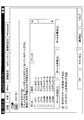
- FIG. 3 is a diagram illustrating an example of a printer name.
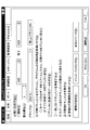
- FIG. 6 is a diagram illustrating an example of sheet definition information.
- FIG. 6 is a diagram illustrating an example of printer setting information (part 1).
- FIG. 6 is a diagram illustrating an example of printer setting information (part 2).
- FIG. 6 is a diagram illustrating an example of printer setting information (part 3).
- FIG. 4 is a diagram illustrating an example of simple printer setting information. The figure which shows an example of a log file.
- FIG. 3 is a flowchart illustrating an example of printer setting processing according to the first exemplary embodiment.
- FIG. 6 is a block diagram illustrating an example of a configuration of a client PC according to a second embodiment.
- 10 is a flowchart illustrating an example of printer setting processing according to the second exemplary embodiment.
- Example 1 desktop virtualization of a client PC by “VDI (virtual desktop infrastructure)” such as a virtual PC type and a local virtual PC type will be described.
- VDI virtual desktop infrastructure
- the user creates, for example, one VDI file in advance and stores it on the server. If the virtual PC type is requested by the client PC, VDI is executed on the server and the screen is transferred to the client PC. In the case of the local virtual PC type, the VDI file is transferred from the server to the client PC, and the VDI is executed on the client PC.
- the creation of the VDI file indicates, for example, installation and setting work of a Windows (registered trademark) OS (Windows (registered trademark) 7 or the like), various applications, and printer-related software.
- the printer software is designed to be compatible with multiple printers, and can be operated by switching the model according to the settings in one execution file.
- FIG. 4 is a diagram illustrating an example of a network system according to the first embodiment.
- an information processing apparatus hereinafter also referred to as a server
- information processing apparatuses hereinafter also referred to as client PCs
- printer for example, an image forming apparatus
- Each device is connected by a network 24.
- FIG. 5 is a block diagram illustrating an example of the configuration of the printer 23 according to the first embodiment.
- a printer 23 illustrated in FIG. 23 includes a printer controller unit 101 and a printer engine unit 102.
- the printer controller unit 101 includes a CPU (Central Processing Unit) 103 and a RAM (Random Access). Memory) 104, flash ROM (Read Only Memory) 105, network I / F unit 106, peripheral control LSI 107, printer engine controller 108, and operation panel 109.
- CPU Central Processing Unit
- RAM Random Access
- Memory Random Access Memory
- flash ROM Read Only Memory
- network I / F unit 106 peripheral control LSI 107
- printer engine controller 108 printer engine controller 108
- operation panel 109 operation panel
- the CPU 103 controls each device, calculates data, and processes in the computer.
- the CPU 103 is an arithmetic device that executes a program stored in the flash ROM 105 or the like.
- the CPU 103 receives data from the input device or the storage device, calculates and processes the data, and outputs the data to the output device or the storage device.
- the RAM 104 is a storage device that stores or temporarily stores programs and data such as an OS and application software that are basic software executed by the CPU 103.
- the flash ROM 105 is a storage device that stores data related to application software and the like, and a printer operation program (firmware).
- the network I / F unit 106 has a communication function connected via a network such as a LAN (Local Area Network) or a WAN (Wide Area Network) constructed by a data transmission path such as a wired and / or wireless line. This is an interface between the device and the printer 23.
- a network such as a LAN (Local Area Network) or a WAN (Wide Area Network) constructed by a data transmission path such as a wired and / or wireless line. This is an interface between the device and the printer 23.
- Peripheral control LSI (Large Scale Integration) 107 is an LSI that controls peripheral devices.
- the printer engine controller 108 controls the printer engine unit 102.
- the operation panel 109 has a touch panel function (including GUI software keys: Graphical It has an LCD (Liquid Crystal Display) with a User Interface. This is a display and / or input device that functions as a UI (User Interface) when using the functions of the printer 23.
- GUI Graphical
- LCD Liquid Crystal Display
- the printer engine unit 102 performs printing on paper as an image data output unit.
- the printer engine unit 102 is in charge of the physical printing process itself, such as actually fixing ink and toner on paper, such as paper feeding, drum charging, laser irradiation, toner application, paper transfer, and fixing. To do.
- FIG. 6 is a block diagram illustrating an example of the configuration of the client PC according to the first embodiment. Since the client PCs 21 and 22 have the same configuration, the client PC 21 will be described below.
- the 6 includes general PC hardware such as a CPU 301, a RAM 302, a network I / F unit 303, an HDD (Hard Disk Drive) 304, and a display unit 305.
- general PC hardware such as a CPU 301, a RAM 302, a network I / F unit 303, an HDD (Hard Disk Drive) 304, and a display unit 305.
- the CPU 301 controls each device, calculates and processes data in a computer.
- the CPU 301 is an arithmetic device that executes a program stored in the HDD 304 or the like.
- the CPU 301 receives data from the input device or the storage device, calculates and processes the data, and outputs the data to the output device or the storage device.
- the RAM 302 is a storage device that stores or temporarily stores programs and data such as an OS and application software that are basic software executed by the CPU 301.
- the HDD 304 is a storage device that stores data related to application software and the like.
- the network I / F unit 303 has a communication function connected via a network such as a LAN (Local Area Network) or a WAN (Wide Area Network) constructed by a data transmission path such as a wired and / or wireless line. This is an interface between the device and the client PC 21.
- a network such as a LAN (Local Area Network) or a WAN (Wide Area Network) constructed by a data transmission path such as a wired and / or wireless line.
- the display unit 305 is, for example, a CRT (Cathode Ray Tube) or an LCD (Liquid Crystal). Display) or the like, and display according to display data input from the CPU 301 is performed.
- CTR Cathode Ray Tube
- LCD Liquid Crystal
- the client PC 21 has a hypervisor 401 and a VM (Virtual Machine) 501 as software layers on a hardware layer.
- the VM 501 is also called a VDI file because it is started by executing the VDI file.
- the hypervisor 401 is a control program for realizing a virtual machine (VM: virtual machine) which is one of computer virtualization technologies.
- VM virtual machine
- the VM 501 is a logical computer that divides a physical computer by virtualization technology and operates with an independent OS. Since the VM 501 functions by executing a VDI file, it is also referred to as a VDI file.
- the hypervisor 401 and the VM (VDI file) 501 are actually stored in the HDD 304 and loaded into the RAM memory 302 and executed by the CPU 301 when the client PC 21 is activated.
- an OS control unit 502 (for example, a Windows (registered trademark) environment) is executed.
- the OS is, for example, Windows (registered trademark).
- programs related to printer printing such as OS management information 507, a printer driver 508, a port monitor 509, and a rung edge monitor 510 are executed.
- the OS management information 507 is, for example, printing related information of a printer.
- the printer driver 508 is a device driver that controls the printer 23.
- the port monitor 509 is a program that manages communication between the printer and Windows (registered trademark). When the port monitor 509 detects a print request or a printer status notification request, the port monitor 509 sets all parameters necessary for establishing communication between the OS and the device requesting the service.
- the rung edge monitor 510 functions as a communication control unit that performs two-way communication with the printer 23 and acquires the status information of the printer 23 while transferring a print job to the printer 23.
- a printer setting program 503 is executed, and the printer setting program 503 functions as a reading unit 504, a collation unit 505, and a changing unit 506.
- a printer setting program 503 is a program for automatically setting setting items related to printing on a printer.
- the reading unit 504 reads the printer setting information 511.
- the printer setting information 511 is setting information stored in the OS control unit 502 and having setting values relating to printing to the printer.
- the setting information is associated with each piece of identification information of the client PC. Details of the printer setting information 511 will be described later.
- any of the following information may be used as the identification information of the client PC.
- IP address IPv6 / IPv4
- the collation unit 505 uses the setting information read by the reading unit 504 to identify the information processing apparatus (client PC) that executes the VM 501 and the printer.
- the identification information in the setting information 511 is collated. When the identification information matches, the collation unit 505 outputs that fact to the change unit 506.
- the changing unit 506 acquires setting information corresponding to the identification information collated by the collating unit 505, and sets various setting values of the OS management information 507, the printer driver 508, the port monitor 509, and the rung edge monitor 510 based on the setting information. change.
- a predetermined default value is set as the initial value of each setting value.
- the log file 512 is history information that stores the identification information of the information processing apparatus when the initial setting change process by the changing unit 506 is completed.
- the OS control unit 502 includes a storage unit that stores printer setting information 511 and a log file.
- FIG. 7A to 7D are diagrams illustrating an example of a local virtual PC type printer setting change process.
- FIG. 7A shows an example of a local virtual PC type configuration.
- the same reference numerals are assigned to the configuration shown in FIG. Note that the server 20 stores a VDI file 501.
- FIG. 7B shows an example of startup processing (part 1) of the client PC 21.
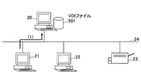
- the server 20 is notified of the activation of the client PC 21 (1).
- FIG. 7C shows an example of startup processing (part 2) of the client PC 21.
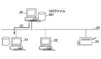
- the server 20 receives the activation notification from the client PC 21, the server 20 downloads the VDI file 501 to the HDD 304 of the client PC 21 (2).
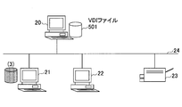
- FIG. 7D shows an example of processing (part 3) when the client PC 21 is started up.
- the client PC 21 executes the downloaded VDI file 501 and starts to start the Windows (registered trademark) environment (OS control unit 502) ( 3).
- OS control unit 502 Windows (registered trademark) environment
- the client PC 21 can automatically change the setting values related to printing on the printer by executing the VDI file 501.
- FIG. 8A to 8D are diagrams illustrating an example of a virtual PC type printer setting change process.
- FIG. 8A shows an example of a virtual PC type configuration.
- the same reference numerals are given in the same manner as in the configuration shown in FIG. Note that the server 20 stores a VDI file 501.
- FIG. 8B shows an example of processing (part 1) when the client PC 21 is started up.
- the server 20 is notified of the activation of the client PC 21 (1).
- FIG. 8C shows an example of processing (part 2) when the client PC 21 is started up.
- the server 20 executes the VDI file 501 and starts activation of the Windows (registered trademark) environment (OS control unit 502) (2).
- FIG. 8D shows an example of processing (part 3) when the client PC 21 is started up.
- the server 20 transfers an execution screen such as the activated Windows (registered trademark) environment to the client PC 21 (3).
- the server 20 can automatically change the setting values related to printing to the printer, and can transfer the execution screen in which the setting values have been changed to the client PC 21. .
- the VDI file 501 stores printer setting information whose settings are changed for each client PC.
- the VM 501 executed by the VDI file can change settings for printing using the setting information of the printer corresponding to the activated client PC.
- printer setting information 511 Next, the printer setting information 511 will be described.
- the information described below is information (setting values) whose setting can be changed by the changing unit 506.
- FIGS. 9A and 9B are diagrams showing an example of the OS management information 507.
- FIG. 9A shows the printer name.
- the printer name is a part of the OS management information 507 and is included in the printer setting information 511.
- FIG. 9B shows the paper definition information.
- the paper definition information is user-specific information, is part of the OS management information 507, and is included in the printer setting information 511.
- the paper definition information includes setting values such as a paper name, a paper size, and a margin.
- FIG. 10A to 10D are diagrams showing examples of printer configuration information.
- FIG. 10A shows administrator setting information.
- the administrator setting information is a part of printer configuration information and is included in the printer setting information 51.
- FIG. 10B shows the sharing setting information.
- the shared setting information is a part of the printer configuration information and is included in the printer setting information 511.
- FIG. 10C shows the port setting information.
- the port setting information is a part of printer configuration information and is included in the printer setting information 511.
- FIG. 10D shows the detailed setting information.
- the detailed setting information is a part of the printer configuration information and is included in the printer setting information 511.
- principalavi 2 is software that can confirm the display of the name of a document being printed, the number of pages that have been printed, a print end notification, and the like from a personal computer that has instructed printing.
- FIGS 11A to 11D are diagrams showing examples of various information of the pudding driver 508.
- FIG. 11A shows basic setting information of the printer driver 508. The basic setting information is included in the printer setting information 511.
- FIG. 11B shows an example of convenient function information of the printer driver 508. The convenient function information is included in the printer setting information 511.
- FIG. 11C shows an example of graphics information of the printer driver 508. The graphics information is included in the printer setting information 511.
- FIG. 11D shows print option information of the printer driver 508. The print option information is included in the printer setting information 511.
- FIG. 12 is a diagram illustrating an example of various information of the port monitor 509.
- each setting value such as the printer IP address and port name is included in the printer setting information 511.
- FIG. 13 is a diagram illustrating an example of various types of information of the rung edge monitor 510.
- each setting value such as a status display during printing and a status display destination is included in the printer setting information 511.
- FIGS. 14A to 14C are diagrams showing examples of the printer setting information 511.
- FIG. 14A to 14C setting information having each setting value shown in FIGS. 9 to 13 is associated with each identification information of the client PC.
- a setting value is input to the setting item to be changed, and the other “-” means a default value.
- a plurality of setting information may be associated with one piece of identification information of the client PC. This is because one client PC may be connected to a plurality of printers.
- the printer setting information 511 can be associated with setting information corresponding to all client PCs that can be connected to the network 24.
- the server 20 has the VDI file for storing the printer setting information 511, so that each client PC can acquire the VDI file and automatically set the printer according to its own device when the VDI file is activated. become.
- the printer setting information 511 is normally stored as plain text, but may be encrypted by various encryption algorithms. Thereby, the security of the printer setting information can be improved.
- FIG. 15 is a diagram illustrating an example of simple printer setting information 511.
- the printer setting information 511 shown in FIG. 15 is associated with “client PC identification information”, “printer name”, “driver name”, “port name”, and “IP address or host name”.
- Example 1 When the address of the client PC 21 is “192.168.14” When the client PC 21 refers to the printer setting information shown in FIG. 15, the client PC identification information does not include the identification information of the client PC 21, so the printer setting change Exit without executing any processing.
- Example 2 The IP address of the client PC 21 is “192.168.1.10” When the IP address of the client PC 22 is “192.168.1.20” When the client PC 21 refers to the printer setting information shown in FIG. 15, the client PC identification information in the DATA 1 line matches the identification information of the client PC 21. Further, when the client PC 22 refers to the printer setting information shown in FIG. 15, the client PC identification information of DATA 2 and the third line matches the identification information of the client PC 22.
- the setting unit 506 changes the setting values as follows.
- -Client PC 21 Printer name: XL-9500 Driver name: XL-9500_Pnavi2 Port name: Fjx — 192.168.1.100 IP address: 192.168.1.100 (printer IP address) ⁇ Client PC22 (1) Printer 1 Printer name: XL-9500 Driver name: XL-9500_Pnavi2 Port name: Fjx — 192.168.1.200 IP address: 192.168.1.200 (printer IP address) (2) Printer 2 Printer name: XL-4360 Driver name: XL-4360_Pnavi2 Port name: Fjx — 192.168.1.201 IP address: 192.168.1.201 (printer IP address) In this way, setting information having various setting values related to printing is changed.
- the default values can be used for the parts other than the changed part. Since the IP address of the printer is information that is likely to be changed when the printer is set up, the operation cost can be reduced if at least the IP address of the printer is included in the setting information.
- the printer setting change process it may be set in advance whether to save the history of various setting changes.
- the VM 501 saves the client PC identification information in the VDI file as the log file 512 shown in FIG. 16 when the initial setting change processing is completed.
- FIG. 16 is a diagram illustrating an example of the log file 512.
- client PC identification information is recorded as a setting change log.
- the client PC identification information shown in FIG. 16 is an IP address.
- the client PC having the identification information recorded in the log file 512 indicates that the setting change process has been completed.
- the VM 501 refers to the log file shown in FIG. 16 as a history of various setting changes at the time of the previous start when the Windows (registered trademark) OS is restarted or when the virtual machine is resumed from the suspended state.
- the VM 501 may skip the setting change process when the client PC identification information includes the identification information of the own device.
- FIG. 17 is a flowchart illustrating an example of the printer setting process according to the first embodiment.
- the hypervisor 401 starts executing the VDI file, expands and activates the VM 501 on the RAM 302.
- step S102 when the activation of the VM 501 is started, the hypervisor 401 starts activation of the OS control unit 502 (for example, Windows (registered trademark)).
- OS control unit 502 for example, Windows (registered trademark)
- step S103 the printer setting program 503 is registered in the startup program when the OS (for example, Windows (registered trademark)) is started, and is started.
- OS for example, Windows (registered trademark)
- the reading unit 504, the collation unit 505, and the changing unit 506 are executed.
- step S104 the reading unit 504 reads the printer setting information 511.
- step S105 the collation unit 505 performs client PC identification processing by inquiring Windows (registered trademark) from the printer setting program 503 using the Windows (registered trademark) API.
- step S106 when the identification of the client PC is completed, the collation unit 505 collates the identification information of the client PC with the identification information of the printer setting information 511.
- step S107 the collation unit 505 determines whether there is identification information that matches the identification information of the client PC in the printer setting information 511. If the identification information is in the printer setting information 511, it indicates that there is a printer whose setting is to be changed.
- step S107-YES If there is a printer to be changed (step S107-YES), the process proceeds to step S108, and if there is no printer to be changed (step S107-NO), the process proceeds to step S109.
- step S108 the changing unit 506 changes various information (each set value) of the OS management information (print related) 507, the printer driver 508, the port monitor 509, and the rung edge monitor 510 using the printer setting information 511.
- step S108 When the change of the setting of one printer is completed (after the process of step S108), the process returns to step S107, and the collation unit 505 determines whether there is any printer that needs to be changed.
- step S109 the printer setting program 503 ends the printer setting process.
- step S110 the VM 501 continues the activation process of the OS control unit 502 (for example, Windows (registered trademark)).
- OS control unit 502 for example, Windows (registered trademark)
- processing shown in FIG. 17 is processed by the server 20 in the case of the virtual PC type, and is processed by the client PCs 21 and 22 in the case of the local virtual PC type, respectively.
- the server 20 has the same configuration as that shown in FIG.
- the printer IP address can be set in accordance with the client PC.
- the printer setting information 511 is normally stored as plain text, but may be encrypted by various encryption algorithms. Thereby, the security of the printer setting information 511 can be improved.
- the setting change process described above is executed as a single program, and the setting change process may be executed at a desired timing by being executed not only at the time of starting but also at an arbitrary timing. For example, when returning from the power saving mode, when restarting the virtual machine from the suspended state, when restarting the OS, or when instructed by a user such as a serviceman.
- Example 2 Next, an information processing apparatus according to the second embodiment will be described. In the second embodiment, an embodiment that does not use the virtualization technology will be described.
- FIG. 18 is a block diagram illustrating an example of the configuration of the client PC 21 according to the second embodiment.
- the client PC 21 in the second embodiment has a configuration in which the hypervisor 401 and the VM 501 are excluded from the configuration in the first embodiment (see FIG. 6).
- the client PC 21 in the second embodiment has a normal OS environment.
- a program for executing the OS control unit 601 is stored in the HDD 304.
- This is one master HDD.
- a plurality of master HDDs are copied.
- the copied HDD is installed in each information processing apparatus.
- each information processing apparatus reads the printer setting information in the HDD at the time of startup, acquires setting information corresponding to the identification information of the own apparatus, and changes the setting values of the setting items related to printing on the printer. be able to.
- the printer setting process is the same as in the first embodiment.
- FIG. 19 is a flowchart illustrating an example of printer setting processing according to the second embodiment.
- the processing flow shown in FIG. 19 is a processing flow excluding step S101 in the processing flow shown in FIG.
- the processing of steps S201 to S209 is the same as the processing of steps S102 to S110 shown in FIG.
- the introduction / operation cost at the time of setting the printer can be reduced.
- the recording medium is a recording medium that records information optically, electrically or magnetically, such as a CD-ROM, flexible disk, magneto-optical disk, etc., and information is electrically recorded such as ROM, flash memory, etc.
- Various types of recording media such as a semiconductor memory can be used.
Landscapes
- Engineering & Computer Science (AREA)
- Theoretical Computer Science (AREA)
- Human Computer Interaction (AREA)
- Physics & Mathematics (AREA)
- General Engineering & Computer Science (AREA)
- General Physics & Mathematics (AREA)
- Accessory Devices And Overall Control Thereof (AREA)
Abstract
情報処理装置を制御する制御部内に、情報処理装置の識別情報毎に関連付けられる、プリンタへの印刷に関する各設定値を有する設定情報と、制御部を実行する情報処理装置の識別情報と、設定情報に関連付けられる識別情報とを照合する照合部と、照合された識別情報に対応する設定情報を取得し、設定情報を用いて、制御部に設定された印刷に関する各設定値を変更する変更部と、を備える。
Description
本発明は、画像形成装置の印刷環境を自動設定する情報処理装置、プリンタ設定方法及びプリンタ設定プログラムに関する。
従来、各企業は、従業員1名あたり1台のクライアントPC(Personal Computer)を配布し各種業務を実施していた。そのため、企業は、多数のクライアントPCを所有していた。
これにより、初期導入時の手間、ハードウェアとしての資産管理、Windows(登録商標)などのソフトウェアライセンスの管理、各種セキュリティ対策の実施、ハードウェアトラブル発生時の機器の入れ替え等、多大なコストがかかっていた。
特に、PCの初期導入に着目すると、以下の2つの大きな負担がある。
・各PCへの各種アプリケーション等のソフトウェアのインストール
・各PCへの各種設定
上記の2点は、費用面、時間面で大きな負担となっていた。
・各PCへの各種アプリケーション等のソフトウェアのインストール
・各PCへの各種設定
上記の2点は、費用面、時間面で大きな負担となっていた。
この課題を解決するため、印刷装置が印刷装置情報をデータベースとして持ち、印刷指示装置がデータベースから印刷装置情報を取得して、プリンタドライバの登録時に印刷装置の持つ搭載機能を自動的に設定する技術がある。
また、前述した各PCへのソフトウェアインストール、設定の手間を低減するため、企業に多数のPCを一括導入する際には、1つのマスターPCを作成し、そのPCにWindows(登録商標)などのOSや各種アプリケーションをインストール、設定していた。そして、マスターPCのHDDを多数コピーし、他のPCに適用、配布するなどを行っていた。
しかし、この方法だと、初期導入時には各PCが同じ環境となっているが、各従業員に配布後は、各自の管理となるため、Windows(登録商標)の各種パッチの適用や、アプリケーションのアップデート等を各PCで管理する必要があり、運用面で問題があった。
そのため、このような運用面での問題を解決する技術として、近年、「VDI(仮想デスクトップ・インフラストラクチャ)」に代表される仮想化技術が開発されている。仮想化デスクトップ技術は、大きくは以下の3つに分類される。
(1)サーバ・ベース型
図1は、サーバ・ベース型の仮想化技術の一例を示す図である。図1に示すように、サーバ・ベース型は、Windows(登録商標)サーバOS(Operating System)のデスクトップを、画面転送プロトコル(例えば、ICA:Independent Computing
Architecture)経由でローカル端末に画面転送する方法である。Windows(登録商標)サーバOSは、例えば、Windows(登録商標) Server 2008 R2などがある。
(1)サーバ・ベース型
図1は、サーバ・ベース型の仮想化技術の一例を示す図である。図1に示すように、サーバ・ベース型は、Windows(登録商標)サーバOS(Operating System)のデスクトップを、画面転送プロトコル(例えば、ICA:Independent Computing
Architecture)経由でローカル端末に画面転送する方法である。Windows(登録商標)サーバOSは、例えば、Windows(登録商標) Server 2008 R2などがある。
ICAは、Citrix Presentation Server上のアプリケーションを利用する際に使用するCitrix(登録商標)独自の通信プロトコルである。
この方法は、ユーザ毎のカスタマイズが不要であり、標準化された定型のデスクトップが各ユーザに提供される。1台のサーバで最大数百人ものユーザをサポートすることができることから、他のどの仮想デスクトップ・テクノロジよりもコスト削減効果を発揮する。
また、サーバ上の仮想プリンタに関連付けられた第1の印刷属性とクライアントが要求する第2の印刷属性とに基づき、第3の印刷属性を生成し、第3の印刷属性に基づいて印刷要求を実行する技術がある。
また、サーバ・ベース型の共有型仮想デスクトップにおいては、クライアントPCに定義されているプリンタドライバをサーバ側にマッピングするマッピングプリンタという技術が一般的に用いられている。
このマッピングプリンタは、Windows(登録商標)サーバOSではクライアントPCに設定されているプリンタの基本的な設定情報しか反映されないため、クライアントPCのプリンタドライバの各種設定情報をサーバ側に反映する技術がある。
この技術は、クライアントPCに定義されているプリンタのドライバ設定をサーバに反映するという面では優れた方式となっている。しかし、各クライアントPCは従来のWindows(登録商標)環境のままであり、PC毎にプリンタドライバをインストール、設定する必要があるため管理コスト削減には役立たない。
以上のように、サーバ・ベース型の共有型仮想デスクトップは、ユーザ毎に共通のWindows(登録商標)環境を使用する場合には適している。しかし、ユーザ毎の設定、ユーザ毎に使用するプリンタ、アプリケーションなどが異なる場合は、すべてのユーザが使用するプリンタ、アプリケーションのインストール、設定が必要となる。
(2)仮想PC型
図2は、仮想PC型の仮想化技術の一例を示す図である。仮想PC型は、図2に示すように、仮想マシン上にインストールしたWindows(登録商標)クライアントOSのデスクトップを、画面転送プロトコル(例えば、Citrix(登録商標)のICA)経由でローカル端末に画面転送する方法である。
(2)仮想PC型
図2は、仮想PC型の仮想化技術の一例を示す図である。仮想PC型は、図2に示すように、仮想マシン上にインストールしたWindows(登録商標)クライアントOSのデスクトップを、画面転送プロトコル(例えば、Citrix(登録商標)のICA)経由でローカル端末に画面転送する方法である。
ユーザ毎にカスタマイズされたデスクトップが必要な場合には、この仮想PC型が適している。
この仮想PC型が「VDI(仮想デスクトップ・インフラストラクチャ)」と言われる。VDI型は、各ユーザのデスクトップが専用の仮想マシンで稼働することから、集中型管理とユーザ単位の完全なパーソナライゼーションの両方のメリットを併せ持つ。
このVDI型は、サーバ上で複数の仮想デスクトップを実行できることからコストダウン効果が高いが、ネットワーク経由でサーバと各クライアントが常時接続されていることが前提となり、ネットワークでの問題発生時の対処など課題も多い。
サーバには、例えば、XenServer、vSpehre、Hyper-Vなどがある。XenServerは、Citrix Systems(以下、Citrix)が提供しているXenベースの仮想化ソフトウェアであり、Xenにエンタープライズ環境に必要なさまざまな管理機能を付加したものである。
vShehreは、仮想化機能を活用して、データセンターを大幅に簡素化されたクラウドコンピューティングインフラストラクチャへと変換する。VMware vSphereを利用することで、設備投資コストと運用コストの削減に仮想化を活用し、クラウドコンピューティングITインフラストラクチャが構築できるようになる。
Hyper-Vは、MicroSoft(登録商標)が提供するハイパーバイザベースのx64向け仮想化システムで、1台のコンピュータ(サーバ)で複数の仮想機械を実現する。
(3)ローカル仮想PC型
図3は、ローカル仮想PC型の仮想化技術の一例を示す図である。ローカル仮想PC型は、比較的最近、実用化が進んでいる技術である。図3に示すように、ローカル仮想PC型は、ローカルPCの仮想ソフトウェア上で仮想マシンを起動し、仮想マシンにインストールされているOSのデスクトップを使用する方法である。前述した(1)と(2)の2つの仮想化技術と違い、オフラインでも使用が可能である。
(3)ローカル仮想PC型
図3は、ローカル仮想PC型の仮想化技術の一例を示す図である。ローカル仮想PC型は、比較的最近、実用化が進んでいる技術である。図3に示すように、ローカル仮想PC型は、ローカルPCの仮想ソフトウェア上で仮想マシンを起動し、仮想マシンにインストールされているOSのデスクトップを使用する方法である。前述した(1)と(2)の2つの仮想化技術と違い、オフラインでも使用が可能である。
このローカル仮想PC型は、外出などが多い営業社員向けのアプローチとして使われることや、個人用及び会社用デスクトップを1つのローカルPCで持つアプローチとして使われることが想定されている。
仮想マシンのイメージが、センターのサーバで集中管理され、例えば、XenClientがインストールされているローカルPC(クライアントPCともいう)からの要求に応じて、必要な仮想マシンを提供することが可能となる。
XenClientは、Microsoft(登録商標)のVirtual PCや、Windows(登録商標)7に搭載されているXP Mode、VMwareのVMware Workstationなどとは異なり、ハイパーバイザーを使用した仮想化ソフトである。
このXenClientは、一度クライアントPCにダウンロードされた後、ネットワークに接続されていなくてもクライアントPC上で実行することが可能である。
以上のような仮想PC型、ローカル仮想PC型では、クライアントPCのWindows(登録商標)環境を仮想化し、複数のクライアントを1つのサーバに集約管理することにより管理コストを削減する取り組みが行われている。これらの技術はDaaS(仮想デスクトップサービス)、IaaS(システムリソースサービス)としてクラウドの基本的な技術となっている。
DaaS/IaaSなどのサービスにおいて、仮想マシンの数、すなわち、いくつの仮想マシンを使用するかで月額費用がカウントされることが多い。よって、運用コストの削減のためには、多数のユーザがいる場合でも極力仮想マシンを少なくすることが求められる。
しかしながら、仮想PC型、ローカル仮想PC型の環境でプリンタを使用する場合、仮想環境内のWindows(登録商標)に使用するプリンタに応じたプリンタドライバをインストールし、印刷を実行するプリンタのIPアドレス、各種印刷設定などを設定しておく必要がある。
通常は、従業員の所属する部署ごとにネットワーク設定や、使用しているプリンタが異なる。そのため、各従業員のクライアントPCごとにインストールするプリンタドライバやプリンタのIPアドレス、印刷設定などを変更する必要があった。
また、クライアントPCを仮想マシンに移行するとクライアントPC毎に使用するプリンタやプリンタのIPアドレス、設定が異なる。よって、クライアントPC毎に仮想マシンを用意する必要があり、DaaS/IaaSサービスにおける導入費用や各仮想マシンのプリンタ設定の管理コストが莫大となっていた。
一例として、1000台の異なるプリンタが存在し、それぞれ別のサブネット内に存在する場合、それぞれのプリンタでIPアドレスが異なるため、それらのプリンタに接続するクライアントPCの仮想マシンは最低1000種類必要となる。そのため、1000種類分の仮想マシンの作成、設定が必要となっていた。
したがって、従来の仮想化技術は、インストールの手間の削減に役立っているものの、各PCのプリンタ設定についてはユーザの負担が大きかった。また、仮想化技術を用いない場合でも、前述したように運用面でのユーザの負担が大きかった。
そこで、開示の技術は、上記問題点に鑑みてなされたものであり、プリンタ設定時の導入/運用コストを低減することができる情報処理装置、プリンタ設定方法及びプリンタ設定プログラムを提供することを目的とする。
開示の一態様における情報処理装置は、情報処理装置を制御する制御部内に、情報処理装置の識別情報毎に関連付けられる、プリンタへの印刷に関する各設定値を有する設定情報と、前記制御部を実行する情報処理装置の識別情報と、前記設定情報に関連付けられる識別情報とを照合する照合部と、照合された識別情報に対応する設定情報を取得し、該設定情報を用いて、前記制御部に設定された印刷に関する各設定値を変更する変更部と、を備える。
開示の技術によれば、プリンタ設定時の導入/運用コストを低減することができる。
20 サーバ
21、22 クライアントPC
23 プリンタ
301 CPU
302 RAM
303 ネットワークI/F部
304 HDD
305 表示部
401 ハイパーバイザー
501 VM
502 OS制御部
503 プリンタ設定プログラム
504 読込部
505 照合部
506 変更部
507 OS管理情報
508 プリンタドライバ
509 ポートモニタ
510 ラングエッジモニタ
511 プリンタ設定情報
512 ログファイル
21、22 クライアントPC
23 プリンタ
301 CPU
302 RAM
303 ネットワークI/F部
304 HDD
305 表示部
401 ハイパーバイザー
501 VM
502 OS制御部
503 プリンタ設定プログラム
504 読込部
505 照合部
506 変更部
507 OS管理情報
508 プリンタドライバ
509 ポートモニタ
510 ラングエッジモニタ
511 プリンタ設定情報
512 ログファイル
以下、図面に基づいて、実施例について説明する。
[実施例1]
実施例1では、仮想PC型、ローカル仮想PC型のような「VDI(仮想デスクトップ・インフラストラクチャ)」によるクライアントPCのデスクトップ仮想化について説明する。
実施例1では、仮想PC型、ローカル仮想PC型のような「VDI(仮想デスクトップ・インフラストラクチャ)」によるクライアントPCのデスクトップ仮想化について説明する。
ユーザは、例えば、事前に1つのVDIファイルを作成し、サーバ上に格納する。クライアントPCの要求により仮想PC型であればサーバ上でVDIを実行し、画面をクライアントPCに転送する。ローカル仮想PC型であれば、VDIファイルをサーバからクライアントPCに転送し、クライアントPC上でVDIを実行する。
VDIファイルの作成とは、例えば、Windows(登録商標)OS(Windows(登録商標)7等)、各種アプリケーション、プリンタ関連ソフトウェアのインストールおよび設定作業を示す。
プリンタの各種ソフトウェアは、複数のプリンタに対応可能な作りとなっており、1つの実行ファイルで設定により機種を切り替えて動作することが可能なものとする。
<構成>
(ネットワーク)
まず、実施例1におけるネットワークシステムについて説明する。図4は、実施例1におけるネットワークシステムの一例を示す図である。図4に示す例では、VDIファイルを格納した情報処理装置(以下、サーバともいう)20、情報処理装置(以下、クライアントPCともいう)21、22、プリンタ(例えば、画像形成装置)23を備える。各装置が、ネットワーク24により接続されている。
(ネットワーク)
まず、実施例1におけるネットワークシステムについて説明する。図4は、実施例1におけるネットワークシステムの一例を示す図である。図4に示す例では、VDIファイルを格納した情報処理装置(以下、サーバともいう)20、情報処理装置(以下、クライアントPCともいう)21、22、プリンタ(例えば、画像形成装置)23を備える。各装置が、ネットワーク24により接続されている。
(プリンタ)
図5は、実施例1におけるプリンタ23の構成の一例を示すブロック図である。図23に示すプリンタ23は、プリンタコントローラ部101、プリンタエンジン部102を備える。
図5は、実施例1におけるプリンタ23の構成の一例を示すブロック図である。図23に示すプリンタ23は、プリンタコントローラ部101、プリンタエンジン部102を備える。
プリンタコントローラ部101は、CPU(Central Processing Unit)103、RAM(Random Access
Memory)104、フラッシュROM(Read Only Memory)105、ネットワークI/F部106、周辺制御LSI107、プリンタエンジンコントローラ108、操作パネル109を備える。
Memory)104、フラッシュROM(Read Only Memory)105、ネットワークI/F部106、周辺制御LSI107、プリンタエンジンコントローラ108、操作パネル109を備える。
CPU103は、コンピュータの中で、各装置の制御やデータの演算、加工を行う。また、CPU103は、フラッシュROM105などに記憶されたプログラムを実行する演算装置であり、入力装置や記憶装置からデータを受け取り、演算、加工した上で、出力装置や記憶装置に出力する。
RAM104は、CPU103が実行する基本ソフトウェアであるOSやアプリケーションソフトウェアなどのプログラムやデータを記憶又は一時保存する記憶装置である。
フラッシュROM105は、アプリケーションソフトウェアなどに関連するデータや、プリンタ動作プログラム(ファームウェア)を記憶する記憶装置である。
ネットワークI/F部106は、有線及び/又は無線回線などのデータ伝送路により構築されたLAN(Local Area Network)、WAN(Wide Area Network)などのネットワークを介して接続された通信機能を有する周辺機器とプリンタ23とのインタフェースである。
周辺制御LSI(Large Scale Integration)107は、周辺デバイスの制御を行うLSIである。プリンタエンジンコントローラ108は、プリンタエンジン部102の制御を行う。
操作パネル109は、タッチパネル機能(GUIのソフトウェアキーを含む:Graphical
User Interface)を備えたLCD(Liquid Crystal Display)を有する。プリンタ23が有する機能を利用する際のUI(User Interface)として機能する表示及び/又は入力装置である。
User Interface)を備えたLCD(Liquid Crystal Display)を有する。プリンタ23が有する機能を利用する際のUI(User Interface)として機能する表示及び/又は入力装置である。
プリンタエンジン部102は、画像データの出力ユニットとして、紙への印刷を行う。
プリンタエンジン部102は、給紙やドラムへの帯電、レーザーの照射、トナーの塗布、用紙への転写、定着など、実際に紙にインクやトナーを定着させるなど、物理的な印刷工程そのものを担当する。
(クライアントPC)
図6は、実施例1におけるクライアントPCの構成の一例を示すブロック図である。クライアントPC21、22は、同様の構成を有するので、以下ではクライアントPC21について説明する。
図6は、実施例1におけるクライアントPCの構成の一例を示すブロック図である。クライアントPC21、22は、同様の構成を有するので、以下ではクライアントPC21について説明する。
図6に示すクライアントPC21は、CPU301、RAM302、ネットワークI/F部303、HDD(Hard Disk Drive)304、表示部305などの一般的なPCのハードウェアを備える。
CPU301は、コンピュータの中で、各装置の制御やデータの演算、加工を行う。また、CPU301は、HDD304などに記憶されたプログラムを実行する演算装置であり、入力装置や記憶装置からデータを受け取り、演算、加工した上で、出力装置や記憶装置に出力する。
RAM302は、CPU301が実行する基本ソフトウェアであるOSやアプリケーションソフトウェアなどのプログラムやデータを記憶又は一時保存する記憶装置である。
HDD304は、アプリケーションソフトウェアなどに関連するデータなどを記憶する記憶装置である。
ネットワークI/F部303は、有線及び/又は無線回線などのデータ伝送路により構築されたLAN(Local Area Network)、WAN(Wide Area Network)などのネットワークを介して接続された通信機能を有する周辺機器とクライアントPC21とのインタフェースである。
表示部305は、例えば、CRT(Cathode Ray Tube)やLCD(Liquid Crystal
Display)等であり、CPU301から入力される表示データに応じた表示が行われる。
Display)等であり、CPU301から入力される表示データに応じた表示が行われる。
クライアントPC21は、ハードウェアのレイアー上にソフトウェアレイアーとしてハイパーバイザー401とVM(Vertual Machine)501を有する。VM501は、VDIファイルを実行することで起動されるため、VDIファイルとも言う。
ハイパーバイザー401は、コンピュータの仮想化技術のひとつである仮想マシン(VM:バーチャルマシン)を実現するための制御プログラムである。
VM501は、仮想化技術によって物理的なコンピュータを分割し、その中で独立したOSを持って動作する論理的なコンピュータのことをいう。VM501は、VDIファイルを実行することで機能するため、VDIファイルともいう。
ハイパーバイザー401及びVM(VDIファイル)501は、実際にはHDD304に格納されており、クライアントPC21起動時などにCPU301によってRAMメモリ302にロードされ、実行される。
VM501内では、OS制御部502(例えば、Windows(登録商標)環境)が実行されている。OSは、例えばWindows(登録商標)とする。そのOS制御部502内に、OS管理情報507や、プリンタドライバ508、ポートモニタ509、ラングエッジモニタ510などプリンタの印刷に関わるプログラムが実行されている。OS管理情報507は、例えば、プリンタの印刷関連情報である。
プリンタドライバ508は、プリンタ23を制御するデバイスドライバのことである。ポートモニタ509は、プリンタとWindows(登録商標)間の通信を司るプログラムである。ポートモニタ509は、印刷要求やプリンタの状態通知要求を検出すると、OSとサービスを要求する装置間の通信を確立するのに必要なすべてのパラメータを設定する。
ラングエッジモニタ510は、プリンタ23と双方向通信を行い、プリンタ23のステータス情報を取得しつつ、プリンタ23へ印刷ジョブを転送する通信制御部として機能する。
OS制御部502内では、プリンタ設定プログラム503が実行され、プリンタ設定プログラム503は、読込部504、照合部505、変更部506として機能する。プリンタ設定プログラム503は、プリンタへの印刷に関する設定項目を自動で設定するプログラムである。
読込部504は、プリンタ設定情報511を読み込む。プリンタ設定情報511は、OS制御部502内に記憶されている、プリンタへの印刷に関する各設定値を有する設定情報である。設定情報は、クライアントPCの識別情報毎に関連付けられている。プリンタ設定情報511の詳細は後述する。
クライアントPCの識別情報は、例えば、以下の情報のいずれかを用いればよい。
・IPアドレス(IPv6/IPv4)
・クライアントPCのホスト名
・ログインユーザ名
・クライアントPCのMACアドレス
照合部505は、読込部504が読み込んだ設定情報を用いて、VM501を実行する情報処理装置(クライアントPC)の識別情報と、プリンタ設定情報511内の識別情報とを照合する。照合部505は、識別情報が一致した場合、その旨を変更部506に出力する。
・IPアドレス(IPv6/IPv4)
・クライアントPCのホスト名
・ログインユーザ名
・クライアントPCのMACアドレス
照合部505は、読込部504が読み込んだ設定情報を用いて、VM501を実行する情報処理装置(クライアントPC)の識別情報と、プリンタ設定情報511内の識別情報とを照合する。照合部505は、識別情報が一致した場合、その旨を変更部506に出力する。
変更部506は、照合部505により照合された識別情報に対応する設定情報を取得し、この設定情報に基づきOS管理情報507、プリンタドライバ508、ポートモニタ509、ラングエッジモニタ510の各種設定値を変更する。各設定値の初期値は、所定のデフォルト値が設定されている。
ログファイル512は、変更部506による初回の設定変更処理が終了した場合に、情報処理装置の識別情報を記憶する履歴情報である。
OS制御部502は、プリンタ設定情報511、ログファイルを記憶する記憶部を有する。
<プリンタ設定変更処理>
次に、プリンタ設定変更の概略処理について説明する。
次に、プリンタ設定変更の概略処理について説明する。
(ローカル仮想PC型)
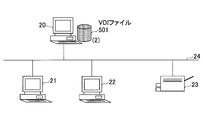
図7A~Dは、ローカル仮想PC型のプリンタ設定変更処理の一例を示す図である。図7Aは、ローカル仮想PC型の構成の一例を示す。図7Aに示す例では、図4に示す構成と同様にし、同じ符号を付す。なお、サーバ20は、VDIファイル501を格納している。
図7A~Dは、ローカル仮想PC型のプリンタ設定変更処理の一例を示す図である。図7Aは、ローカル仮想PC型の構成の一例を示す。図7Aに示す例では、図4に示す構成と同様にし、同じ符号を付す。なお、サーバ20は、VDIファイル501を格納している。
図7Bは、クライアントPC21の起動時処理(その1)の一例を示す。図7Bに示す例では、クライアントPC21の電源が投入されると、サーバ20に対し、クライアントPC21の起動が通知される(1)。
図7Cは、クライアントPC21の起動時処理(その2)の一例を示す。図7Cに示す例では、サーバ20は、クライアントPC21から起動通知を受信すると、VDIファイル501をクライアントPC21のHDD304にダウンロードさせる(2)。
図7Dは、クライアントPC21の起動時処理(その3)の一例を示す。図7Dに示す例では、クライアントPC21にVDIファイル501のダウンロードが完了すると、クライアントPC21は、ダウンロードしたVDIファイル501を実行し、Windows(登録商標)環境(OS制御部502)の起動を開始する(3)。
クライアントPC21は、VDIファイル501を実行することで、プリンタへの印刷に関する各設定値を自動で設定変更することができる。
(仮想PC型)
図8A~Dは、仮想PC型のプリンタ設定変更処理の一例を示す図である。図8Aは、仮想PC型の構成の一例を示す。図8Aに示す例では、図4に示す構成と同様にし、同じ符号を付す。なお、サーバ20は、VDIファイル501を格納している。
図8A~Dは、仮想PC型のプリンタ設定変更処理の一例を示す図である。図8Aは、仮想PC型の構成の一例を示す。図8Aに示す例では、図4に示す構成と同様にし、同じ符号を付す。なお、サーバ20は、VDIファイル501を格納している。
図8Bは、クライアントPC21の起動時処理(その1)の一例を示す。図8Bに示す例では、クライアントPC21の電源が投入されると、サーバ20に対し、クライアントPC21の起動が通知される(1)。
図8Cは、クライアントPC21の起動時処理(その2)の一例を示す。図8Cに示す例では、サーバ20は、クライアントPC21から起動通知を受信すると、VDIファイル501を実行し、Windows(登録商標)環境(OS制御部502)の起動を開始する(2)。
図8Dは、クライアントPC21の起動時処理(その3)の一例を示す。図8Dに示す例では、サーバ20は、起動されたWindows(登録商標)環境などの実行画面をクライアントPC21に転送する(3)。
サーバ20は、VDIファイル501を実行することで、プリンタへの印刷に関する各設定値を自動で設定変更することができ、各設定値が設定変更された実行画面をクライアントPC21に転送することができる。
VDIファイル501には、クライアントPC毎に設定変更されるプリンタの設定情報が格納されている。VDIファイルにより実行されるVM501は、起動したクライアントPCに対応するプリンタの設定情報を用いて、印刷に関する各設定を設定変更することができる。
(プリンタ設定情報)
次に、プリンタ設定情報511について説明する。以下に説明する情報が、変更部506により設定変更可能な情報(設定値)である。
次に、プリンタ設定情報511について説明する。以下に説明する情報が、変更部506により設定変更可能な情報(設定値)である。
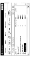
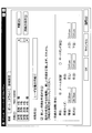
図9A、Bは、OS管理情報507の一例を示す図である。図9Aは、プリンタ名を示す。プリンタ名は、OS管理情報507の一部であり、プリンタ設定情報511に含まれる。図9Bは、用紙定義情報を示す。用紙定義情報は、ユーザ固有の情報で、OS管理情報507の一部であり、プリンタ設定情報511に含まれる。用紙定義情報は、用紙名、用紙サイズ、余白などの各設定値を含む。
図10A~Dは、プリンタの構成情報の一例を示す図である。図10Aは、管理者設定情報を示す。管理者設定情報は、プリンタの構成情報の一部であり、プリンタ設定情報51に含まれる。図10Bは、共有設定情報を示す。共有設定情報は、プリンタの構成情報の一部であり、プリンタ設定情報511に含まれる。
図10Cは、ポート設定情報を示す。ポート設定情報は、プリンタの構成情報の一部であり、プリンタ設定情報511に含まれる。図10Dは、詳細設定情報を示す。詳細設定情報は、プリンタの構成情報の一部であり、プリンタ設定情報511に含まれる。なお、printianavi2は、印刷中の文書名や印刷を完了したページ数の表示、印刷終了通知などを、印刷を指示したパソコンから確認できるソフトウェアである。
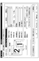
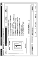
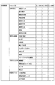
図11A~Dは、プリンドライバ508の各種情報の一例を示す図である。図11Aは、プリンタドライバ508の基本設定情報を示す。基本設定情報は、プリンタ設定情報511に含まれる。図11Bは、プリンタドライバ508の便利機能情報の一例を示す。便利機能情報は、プリンタ設定情報511に含まれる。
図11Cは、プリンタドライバ508のグラフィックス情報の一例を示す。グラフィックス情報は、プリンタ設定情報511に含まれる。図11Dは、プリンタドライバ508の印刷オプション情報を示す。印刷オプション情報は、プリンタ設定情報511に含まれる。
図12は、ポートモニタ509の各種情報の一例を示す図である。図12に示す例では、プリンタのIPアドレス、ポート名などの各設定値が、プリンタ設定情報511に含まれる。
図13は、ラングエッジモニタ510の各種情報の一例を示す図である。図13に示す例では、印刷中のステータス表示やステータスの表示先などの各設定値が、プリンタ設定情報511に含まれる。
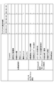
図14A~Cは、プリンタ設定情報511の一例を示す図である。図14A~Cに示すように、クライアントPCの識別情報毎に、図9~13の各設定値を有する設定情報が関連付けられている。図14A~Cに示す例では、変更される設定項目に設定値が入力されており、その他の「―」は、デフォルト値を意味する。
なお、図14A~Cに示すように、クライアントPCの一つの識別情報に、複数の設定情報が関連付けられてもよい。1つのクライアントPCが複数のプリンタに接続されることもあるからである。また、プリンタ設定情報511には、ネットワーク24に接続されうる全てのクライアントPCに対応する設定情報を関連付けておくことができる。
これにより、サーバ20がプリンタ設定情報511を格納するVDIファイルを有することで、各クライアントPCは、VDIファイルを取得し、VDIファイルの起動時に、自装置に応じたプリンタの設定が自動でできるようになる。なお、プリンタ設定情報511は、通常は平文として格納されているが、各種暗号化アルゴリズムにより暗号化されていてもよい。これにより、プリンタ設定情報のセキュリティを向上させることができる。
<設定変更例>
次に、プリンタ設定情報511を用いた設定変更の簡単な例について説明する。図15は、簡易なプリンタ設定情報511の一例を示す図である。図15に示すプリンタ設定情報511は、「クライアントPCの識別情報」、「プリンタ名」、「ドライバ名」、「ポート名」、「IPアドレスあるいはホスト名」が関連付けられている。
次に、プリンタ設定情報511を用いた設定変更の簡単な例について説明する。図15は、簡易なプリンタ設定情報511の一例を示す図である。図15に示すプリンタ設定情報511は、「クライアントPCの識別情報」、「プリンタ名」、「ドライバ名」、「ポート名」、「IPアドレスあるいはホスト名」が関連付けられている。
(例1)
・クライアントPC21のアドレスが「192.168.14」の場合
クライアントPC21は、図15に示すプリンタ設定情報を参照すると、クライアントPC識別情報の中にクライアントPC21の識別情報がないため、プリンタの設定変更処理を実行せずに終了する。
・クライアントPC21のアドレスが「192.168.14」の場合
クライアントPC21は、図15に示すプリンタ設定情報を参照すると、クライアントPC識別情報の中にクライアントPC21の識別情報がないため、プリンタの設定変更処理を実行せずに終了する。
(例2)
・クライアントPC21のIPアドレスが「192.168.1.10」
・クライアントPC22のIPアドレスが「192.168.1.20」の場合
クライアントPC21は、図15に示すプリンタ設定情報を参照すると、DATA1行のクライアントPC識別情報がクライアントPC21の識別情報と一致する。また、クライアントPC22は、図15に示すプリンタ設定情報を参照すると、DATA2、3行のクライアントPC識別情報と、クライアントPC22の識別情報とが一致する。
・クライアントPC21のIPアドレスが「192.168.1.10」
・クライアントPC22のIPアドレスが「192.168.1.20」の場合
クライアントPC21は、図15に示すプリンタ設定情報を参照すると、DATA1行のクライアントPC識別情報がクライアントPC21の識別情報と一致する。また、クライアントPC22は、図15に示すプリンタ設定情報を参照すると、DATA2、3行のクライアントPC識別情報と、クライアントPC22の識別情報とが一致する。
よって、変更部506により、以下のように、各設定値が設定変更される。
・クライアントPC21
プリンタ名:XL-9500
ドライバ名:XL-9500_Pnavi2
ポート名:Fjx_192.168.1.100
IPアドレス:192.168.1.100(プリンタのIPアドレス)
・クライアントPC22
(1)プリンタ1
プリンタ名:XL-9500
ドライバ名:XL-9500_Pnavi2
ポート名:Fjx_192.168.1.200
IPアドレス:192.168.1.200(プリンタのIPアドレス)
(2)プリンタ2
プリンタ名:XL-4360
ドライバ名:XL-4360_Pnavi2
ポート名:Fjx_192.168.1.201
IPアドレス:192.168.1.201(プリンタのIPアドレス)
このように、印刷に関する各種の設定値を有する設定情報は変更される。なお、変更箇所以外のものは、デフォルトの値そのままでよい。プリンタのIPアドレスは、プリンタの設定時に変更される可能性が高い情報であるため、少なくともプリンタのIPアドレスを設定情報に含めておけば、運用コストを低減することができる。
・クライアントPC21
プリンタ名:XL-9500
ドライバ名:XL-9500_Pnavi2
ポート名:Fjx_192.168.1.100
IPアドレス:192.168.1.100(プリンタのIPアドレス)
・クライアントPC22
(1)プリンタ1
プリンタ名:XL-9500
ドライバ名:XL-9500_Pnavi2
ポート名:Fjx_192.168.1.200
IPアドレス:192.168.1.200(プリンタのIPアドレス)
(2)プリンタ2
プリンタ名:XL-4360
ドライバ名:XL-4360_Pnavi2
ポート名:Fjx_192.168.1.201
IPアドレス:192.168.1.201(プリンタのIPアドレス)
このように、印刷に関する各種の設定値を有する設定情報は変更される。なお、変更箇所以外のものは、デフォルトの値そのままでよい。プリンタのIPアドレスは、プリンタの設定時に変更される可能性が高い情報であるため、少なくともプリンタのIPアドレスを設定情報に含めておけば、運用コストを低減することができる。
また、プリンタの設定変更処理は、各種設定変更が完了した履歴の保存有無を事前に設定しておいてもよい。VM501は、履歴を保存する設定が行われている場合に、初回の設定変更処理が終了した時に、クライアントPC識別情報を図16に示すログファイル512としてVDIファイル内に保存する。
図16は、ログファイル512の一例を示す図である。図16に示す例では、設定変更ログとして、クライアントPC識別情報が記録される。図16に示すクライアントPC識別情報は、IPアドレスとする。このログファイル512に記録された識別情報を有するクライアントPCは、設定変更処理が完了していることを表す。
また、VM501は、Windows(登録商標)OSの再起動時、または、仮想マシンが中断状態から再開するときに、前回起動時の各種設定変更の履歴として図16に示すログファイルを参照する。VM501は、クライアントPC識別情報に自装置の識別情報がある場合、設定変更処理をスキップするようにしてもよい。
これにより、同じ設定を再度繰り返すことを防止でき、クライアントPCに処理負荷をかけずにすむ。
<動作>
次に、実施例1における情報処理装置の動作について説明する。図17は、実施例1におけるプリンタ設定処理の一例を示すフローチャートである。図17に示すステップS101で、ハイパーバイザー401は、VDIファイルを実行開始し、VM501をRAM302上に展開、起動する。
次に、実施例1における情報処理装置の動作について説明する。図17は、実施例1におけるプリンタ設定処理の一例を示すフローチャートである。図17に示すステップS101で、ハイパーバイザー401は、VDIファイルを実行開始し、VM501をRAM302上に展開、起動する。
ステップS102で、ハイパーバイザー401は、VM501の起動が開始されると、OS制御部502(例えばWindows(登録商標))の起動を開始する。
ステップS103で、プリンタ設定プログラム503は、例えばOS(例えばWindows(登録商標))の起動時にスタートアッププログラムに登録されており、起動される。プリンタ設定プログラム503が起動されることで、読込部504、照合部505、変更部506が実行される。
ステップS104で、読込部504は、プリンタ設定情報511の読み込みを行う。
ステップS105で、照合部505は、クライアントPCの識別処理を、プリンタ設定プログラム503からWindows(登録商標)のAPIを利用してWindows(登録商標)に問い合わせることによって行う。
ステップS106で、照合部505は、クライアントPCの識別が完了したら、クライアントPCの識別情報とプリンタ設定情報511の識別情報との照合を行う。
ステップS107で、照合部505は、クライアントPCの識別情報と一致する識別情報が、プリンタ設定情報511内にあるか否かを判定する。識別情報がプリンタ設定情報511内にある場合、それは、設定変更を行うプリンタがあることを表す。
変更するプリンタが存在すれば(ステップS107-YES)ステップS108に進み、変更するプリンタが存在しなければ(ステップS107-NO)ステップS109に進む。
ステップS108で、変更部506は、OS管理情報(印刷関連)507、プリンタドライバ508、ポートモニタ509、ラングエッジモニタ510の各種情報(各設定値)を、プリンタ設定情報511を用いて変更する。
1台のプリンタ設定の変更が完了したら(ステップS108の処理後)、ステップS107に戻り、照合部505は、設定変更が必要なプリンタが残っていないかを判断する。
ステップS109で、プリンタ設定プログラム503は、プリンタ設定処理を終了する。
ステップS110で、VM501は、OS制御部502(例えばWindows(登録商標))の起動処理を継続する。
なお、図17に示す処理は、仮想PC型の場合はサーバ20が処理し、ローカル仮想PC型の場合は、クライアントPC21、22がそれぞれ処理する。仮想PC型の場合、サーバ20は、図6に示した構成と同様の構成を備える。
以上、実施例1によれば、仮想化技術において、プリンタ設定時の導入/運用コストを低減することができる。また、実施例1によれば、プリンタの設定を、各クライアントPCに行わなくてすみ、例えばプリンタのIPアドレスの設定などを、クライアントPCに応じて行うことができる。
また、実施例1によれば、プリンタ設定情報511は、同一のクライアントPC(=1つの仮想マシン)向けに各設定項目を複数持つことができ、その組み合わせを保持することができる。
また、プリンタ設定情報511は、通常は平文として格納されているが、各種暗号化アルゴリズムにより暗号化してもよい。これにより、プリンタ設定情報511のセキュリティを高めることができる。
また、前述した設定変更処理は、単体のプログラムとして実行され、起動時のみでなく、任意のタイミングで実行することにより、希望したタイミングで設定変更処理を実行してもよい。例えば、省電力モードからの復帰時、仮想マシンが中断状態からの再開時、OSの再起動時、又は、サービスマンなどのユーザから指示された時などである。
[実施例2]
次に、実施例2における情報処理装置について説明する。実施例2では、仮想化技術を用いない実施例について説明する。
次に、実施例2における情報処理装置について説明する。実施例2では、仮想化技術を用いない実施例について説明する。
<構成>
図18は、実施例2におけるクライアントPC21の構成の一例を示すブロック図である。図18に示すように実施例2におけるクライアントPC21は、実施例1の構成(図6参照)から、ハイパーバイザー401、VM501を除いた構成を有する。これにより、実施例2におけるクライアントPC21は、通常のOS環境を有する。
図18は、実施例2におけるクライアントPC21の構成の一例を示すブロック図である。図18に示すように実施例2におけるクライアントPC21は、実施例1の構成(図6参照)から、ハイパーバイザー401、VM501を除いた構成を有する。これにより、実施例2におけるクライアントPC21は、通常のOS環境を有する。
実施例2では、例えば、OS制御部601を実行するプログラムがHDD304に格納されている。これを1つのマスターHDDとする。このマスターHDDを複数コピーする。コピーされたHDDを各情報処理装置に設置する。
これにより、各情報処理装置は、起動時にHDD内のプリンタ設定情報を読み出し、自装置の識別情報に対応する設定情報を取得し、プリンタへの印刷に関する各設定項目の各設定値を設定変更することができる。プリンタ設定処理は、実施例1と同様である。
従来技術では、プリンタのIPアドレスなどを各情報処理装置に対して設定する必要があり、非常に煩雑な処理を強いられていた。一方、実施例2では、各情報処理装置の識別情報に関連付けて印刷に関する各設定値を有する設定情報をOS環境内に保持させる。これにより、情報処理装置毎に応じて自動で印刷に関する各設定を行うことができ、プリンタの設定時に、導入/運用コストを低減することができる。
<動作>
次に、実施例2における情報処理装置の動作について説明する。図19は、実施例2におけるプリンタ設定処理の一例を示すフローチャートである。図19に示す処理フローは、図17に示す処理フローのうち、ステップS101を除いた処理フローである。ステップS201~S209の処理は、図17に示すステップS102~S110の処理とそれぞれ同様である。
次に、実施例2における情報処理装置の動作について説明する。図19は、実施例2におけるプリンタ設定処理の一例を示すフローチャートである。図19に示す処理フローは、図17に示す処理フローのうち、ステップS101を除いた処理フローである。ステップS201~S209の処理は、図17に示すステップS102~S110の処理とそれぞれ同様である。
以上、実施例2によれば、仮想化技術を用いない場合でも、プリンタの設定時の導入/運用コストを低減することができる。
なお、前述した各実施例で説明したプリンタ設定プログラム503を記録媒体に記録することで、各実施例でのプリンタの設定変更処理をコンピュータに実施させることができる。
なお、記録媒体は、CD-ROM、フレキシブルディスク、光磁気ディスク等の様に情報を光学的,電気的或いは磁気的に記録する記録媒体、ROM、フラッシュメモリ等の様に情報を電気的に記録する半導体メモリ等、様々なタイプの記録媒体を用いることができる。
以上、実施例について詳述したが、特定の実施例に限定されるものではなく、特許請求の範囲に記載された範囲内において、種々の変形及び変更が可能である。また、前述した実施例の構成要素を全部又は複数を組み合わせることも可能である。
Claims (7)
- 情報処理装置を制御する制御部内に、
情報処理装置の識別情報毎に関連付けられる、プリンタへの印刷に関する各設定値を有する設定情報と、
前記制御部を実行する情報処理装置の識別情報と、前記設定情報に関連付けられる識別情報とを照合する照合部と、
照合された識別情報に対応する設定情報を取得し、該設定情報を用いて、前記制御部に設定された印刷に関する各設定値を変更する変更部と、
を備える情報処理装置。 - 前記制御部は、仮想マシンの実行により起動処理が行われて実行可能となる請求項1記載の情報処理装置。
- 前記制御部は、
各設定値の変更が完了した場合、変更が完了した情報処理装置の識別情報をログファイルとして保持し、該制御部の再起動時、又は前記仮想マシンの中断状態からの復帰時に、前記ログファイルに自装置の識別情報がなければ、前記設定情報に基づく変更処理を行う請求項2記載の情報処理装置。 - 前記設定情報は、少なくとも前記プリンタのIPアドレスを含む請求項1乃至3いずれか一項に記載の情報処理装置。
- 前記設定情報は、前記仮想マシンが実行される情報処理装置毎に、該情報処理装置が利用する各プリンタへの印刷に関する各設定値が保持される請求項2記載の情報処理装置。
- 情報処理装置を制御する制御部内に格納された、情報処理装置の識別情報毎に関連付けられる、プリンタへの印刷に関する各設定値を有する設定情報を読込み、
前記制御部を実行する情報処理装置の識別情報と、前記設定情報に関連付けられる識別情報とを照合し、
照合された識別情報に対応する設定情報を取得し、該設定情報を用いて、前記制御部に設定された印刷に関する各設定値を変更する、
処理をコンピュータが実行するプリンタ設定方法。 - 情報処理装置を制御する制御部内に格納された、情報処理装置の識別情報毎に関連付けられる、プリンタへの印刷に関する各設定値を有する設定情報を読込み、
前記制御部を実行する情報処理装置の識別情報と、前記設定情報に関連付けられる識別情報とを照合し、
照合された識別情報に対応する設定情報を取得し、該設定情報を用いて、前記制御部に設定された印刷に関する各設定値を変更する、
処理をコンピュータに実行させるプリンタ設定プログラム。
Priority Applications (1)
| Application Number | Priority Date | Filing Date | Title |
|---|---|---|---|
| PCT/JP2011/058225 WO2012131981A1 (ja) | 2011-03-31 | 2011-03-31 | 情報処理装置、プリンタ設定方法及びプリンタ設定プログラム |
Applications Claiming Priority (1)
| Application Number | Priority Date | Filing Date | Title |
|---|---|---|---|
| PCT/JP2011/058225 WO2012131981A1 (ja) | 2011-03-31 | 2011-03-31 | 情報処理装置、プリンタ設定方法及びプリンタ設定プログラム |
Publications (1)
| Publication Number | Publication Date |
|---|---|
| WO2012131981A1 true WO2012131981A1 (ja) | 2012-10-04 |
Family
ID=46929802
Family Applications (1)
| Application Number | Title | Priority Date | Filing Date |
|---|---|---|---|
| PCT/JP2011/058225 Ceased WO2012131981A1 (ja) | 2011-03-31 | 2011-03-31 | 情報処理装置、プリンタ設定方法及びプリンタ設定プログラム |
Country Status (1)
| Country | Link |
|---|---|
| WO (1) | WO2012131981A1 (ja) |
Cited By (1)
| Publication number | Priority date | Publication date | Assignee | Title |
|---|---|---|---|---|
| CN115328409A (zh) * | 2022-04-02 | 2022-11-11 | 深信服科技股份有限公司 | 打印处理方法、虚拟机、虚拟机管理装置、设备及系统 |
Citations (4)
| Publication number | Priority date | Publication date | Assignee | Title |
|---|---|---|---|---|
| JP2004252759A (ja) * | 2003-02-20 | 2004-09-09 | Ricoh Co Ltd | ドライバのインストール方法とインストール制御プログラム |
| JP2005044001A (ja) * | 2003-07-23 | 2005-02-17 | Canon Sales Co Inc | サーバ装置およびプリンタ設定方法およびプログラムおよび記録媒体 |
| JP2006338225A (ja) * | 2005-06-01 | 2006-12-14 | Hitachi Ltd | コンピュータの自動インストール方法 |
| JP2011008386A (ja) * | 2009-06-24 | 2011-01-13 | Brother Industries Ltd | 情報処理システム、周辺機器、プログラム |
-
2011
- 2011-03-31 WO PCT/JP2011/058225 patent/WO2012131981A1/ja not_active Ceased
Patent Citations (4)
| Publication number | Priority date | Publication date | Assignee | Title |
|---|---|---|---|---|
| JP2004252759A (ja) * | 2003-02-20 | 2004-09-09 | Ricoh Co Ltd | ドライバのインストール方法とインストール制御プログラム |
| JP2005044001A (ja) * | 2003-07-23 | 2005-02-17 | Canon Sales Co Inc | サーバ装置およびプリンタ設定方法およびプログラムおよび記録媒体 |
| JP2006338225A (ja) * | 2005-06-01 | 2006-12-14 | Hitachi Ltd | コンピュータの自動インストール方法 |
| JP2011008386A (ja) * | 2009-06-24 | 2011-01-13 | Brother Industries Ltd | 情報処理システム、周辺機器、プログラム |
Cited By (1)
| Publication number | Priority date | Publication date | Assignee | Title |
|---|---|---|---|---|
| CN115328409A (zh) * | 2022-04-02 | 2022-11-11 | 深信服科技股份有限公司 | 打印处理方法、虚拟机、虚拟机管理装置、设备及系统 |
Similar Documents
| Publication | Publication Date | Title |
|---|---|---|
| US8924703B2 (en) | Secure virtualization environment bootable from an external media device | |
| JP5784482B2 (ja) | 情報処理装置および通信制御方法 | |
| US10324744B2 (en) | Triggering application attachment based on service login | |
| CN102214118A (zh) | 一种虚拟机控制方法、系统及装置 | |
| US20120117611A1 (en) | Controlling information disclosure during application streaming and publishing | |
| US9083604B2 (en) | Information processing apparatus, client management system, and client management method | |
| US11194605B1 (en) | Synchronizing settings associated with virtual computing environments | |
| CN101727339A (zh) | 控制器械设定方法及程序 | |
| US20120281251A1 (en) | Method and system for configuring printer drivers for multiple printing devices | |
| JP6393612B2 (ja) | システムのバックアップ装置及びバックアップ方法 | |
| JP5346405B2 (ja) | ネットワークシステム | |
| JP6882060B2 (ja) | 情報処理装置、ドライバのインストール方法およびプログラム | |
| US11212168B2 (en) | Apparatuses and methods for remote computing node initialization using a configuration template and resource pools | |
| JP2019139661A (ja) | プリントシステム、ジョブリスト提供方法、プリントサーバ装置、管理サーバ装置及びプログラム | |
| US20130238673A1 (en) | Information processing apparatus, image file creation method, and storage medium | |
| JP7455601B2 (ja) | 情報処理装置とその制御方法、及びプログラム | |
| JP2013182367A (ja) | プリントキュー作成プログラム及びプリントキュー作成方法 | |
| JP2018147300A (ja) | 情報処理装置、情報処理方法及びプログラム | |
| JP2013225738A (ja) | 画像形成装置及びジョブ管理方法 | |
| WO2012131981A1 (ja) | 情報処理装置、プリンタ設定方法及びプリンタ設定プログラム | |
| US12039208B2 (en) | Printing system allowing administrator to conveniently limit function of print device when used by general user, information processing apparatus, control method, and storage medium | |
| Zacker | Installing and Configuring Windows Server 2012 R2: Exam 70-410 | |
| JP5766065B2 (ja) | 管理システム、サーバ装置、管理方法およびコンピュータプログラム | |
| JP5929400B2 (ja) | プリンター設定システムおよびプリンター設定システムの制御方法。 | |
| US20160357585A1 (en) | Triggering application attachment based on state changes of virtual machines |
Legal Events
| Date | Code | Title | Description |
|---|---|---|---|
| 121 | Ep: the epo has been informed by wipo that ep was designated in this application |
Ref document number: 11861974 Country of ref document: EP Kind code of ref document: A1 |
|
| NENP | Non-entry into the national phase |
Ref country code: DE |
|
| 122 | Ep: pct application non-entry in european phase |
Ref document number: 11861974 Country of ref document: EP Kind code of ref document: A1 |
|
| NENP | Non-entry into the national phase |
Ref country code: JP |