WO2012131944A1 - 大気環境測定装置、大気環境測定方法及び大気環境測定システム - Google Patents
大気環境測定装置、大気環境測定方法及び大気環境測定システム Download PDFInfo
- Publication number
- WO2012131944A1 WO2012131944A1 PCT/JP2011/058051 JP2011058051W WO2012131944A1 WO 2012131944 A1 WO2012131944 A1 WO 2012131944A1 JP 2011058051 W JP2011058051 W JP 2011058051W WO 2012131944 A1 WO2012131944 A1 WO 2012131944A1
- Authority
- WO
- WIPO (PCT)
- Prior art keywords
- mass sensor
- atmospheric environment
- casing
- mass
- measurement data
- Prior art date
- Legal status (The legal status is an assumption and is not a legal conclusion. Google has not performed a legal analysis and makes no representation as to the accuracy of the status listed.)
- Ceased
Links
Images



Classifications
-
- G—PHYSICS
- G01—MEASURING; TESTING
- G01N—INVESTIGATING OR ANALYSING MATERIALS BY DETERMINING THEIR CHEMICAL OR PHYSICAL PROPERTIES
- G01N5/00—Analysing materials by weighing, e.g. weighing small particles separated from a gas or liquid
- G01N5/02—Analysing materials by weighing, e.g. weighing small particles separated from a gas or liquid by absorbing or adsorbing components of a material and determining change of weight of the adsorbent, e.g. determining moisture content
-
- G—PHYSICS
- G01—MEASURING; TESTING
- G01N—INVESTIGATING OR ANALYSING MATERIALS BY DETERMINING THEIR CHEMICAL OR PHYSICAL PROPERTIES
- G01N29/00—Investigating or analysing materials by the use of ultrasonic, sonic or infrasonic waves; Visualisation of the interior of objects by transmitting ultrasonic or sonic waves through the object
- G01N29/02—Analysing fluids
- G01N29/022—Fluid sensors based on microsensors, e.g. quartz crystal-microbalance [QCM], surface acoustic wave [SAW] devices, tuning forks, cantilevers, flexural plate wave [FPW] devices
-
- G—PHYSICS
- G01—MEASURING; TESTING
- G01G—WEIGHING
- G01G3/00—Weighing apparatus characterised by the use of elastically-deformable members, e.g. spring balances
- G01G3/12—Weighing apparatus characterised by the use of elastically-deformable members, e.g. spring balances wherein the weighing element is in the form of a solid body stressed by pressure or tension during weighing
- G01G3/13—Weighing apparatus characterised by the use of elastically-deformable members, e.g. spring balances wherein the weighing element is in the form of a solid body stressed by pressure or tension during weighing having piezoelectric or piezoresistive properties
-
- G—PHYSICS
- G01—MEASURING; TESTING
- G01G—WEIGHING
- G01G3/00—Weighing apparatus characterised by the use of elastically-deformable members, e.g. spring balances
- G01G3/12—Weighing apparatus characterised by the use of elastically-deformable members, e.g. spring balances wherein the weighing element is in the form of a solid body stressed by pressure or tension during weighing
- G01G3/16—Weighing apparatus characterised by the use of elastically-deformable members, e.g. spring balances wherein the weighing element is in the form of a solid body stressed by pressure or tension during weighing measuring variations of frequency of oscillations of the body
-
- G—PHYSICS
- G01—MEASURING; TESTING
- G01N—INVESTIGATING OR ANALYSING MATERIALS BY DETERMINING THEIR CHEMICAL OR PHYSICAL PROPERTIES
- G01N1/00—Sampling; Preparing specimens for investigation
- G01N1/02—Devices for withdrawing samples
- G01N1/22—Devices for withdrawing samples in the gaseous state
- G01N1/2273—Atmospheric sampling
Definitions
- the present invention relates to an atmospheric environment measuring device, an atmospheric environment measuring method, and an atmospheric environment measuring system.
- the conventional atmospheric environment measuring device is large, there is a limit to the installation location. Moreover, since the conventional atmospheric environment measuring device is expensive, it has been difficult to arrange it at various locations from the viewpoint of cost. For this reason, conventionally, it was not easy to measure a wide range of atmospheric environment without spending a huge amount of money.
- An object of the present invention is to provide an atmospheric environment measuring device, an atmospheric environment measuring method, and an atmospheric environment measuring system that can realize atmospheric environment measurement at low cost.
- the first filter disposed in the casing and adsorbing a gas component to be detected is disposed in the casing between the intake port of the casing and the first filter.
- a second mass sensor disposed downstream of the filter and having a second piezoelectric vibration element, the resonance frequency of which varies according to the mass of the substance attached to the surface of the second piezoelectric vibration element;
- an atmospheric environment measuring device including a fan that is arranged downstream of the second mass sensor and that allows air to flow from the intake port toward the exhaust port of the casing.
- the first filter disposed in the casing and adsorbing the component of the gas to be detected, and the casing between the intake port of the casing and the first filter.
- a first mass sensor having a first piezoelectric vibration element, the resonance frequency of which changes according to the mass of the substance attached to the surface of the first piezoelectric vibration element, and the first in the casing.
- An atmospheric environment measuring device having a transmission unit for wirelessly transmitting constant data; and the measurement data transmitted from the atmospheric environment measuring device is acquired via a network, and based on the acquired measurement data, There is provided an atmospheric environment measurement system including a processing device for performing measurement.
- a first filter that is disposed in the casing and adsorbs a component of a gas to be detected, and the inside of the casing between the intake port of the casing and the first filter.
- a first mass sensor having a first piezoelectric vibration element, the resonance frequency of which varies according to the mass of the substance attached to the surface of the first piezoelectric vibration element, and the first mass sensor in the casing.
- a second mass sensor disposed after the first filter and having a second piezoelectric vibration element, the resonance frequency of which varies according to the mass of the substance attached to the surface of the second piezoelectric vibration element;
- a fan disposed in a stage subsequent to the second mass sensor in the casing and configured to flow air from the air inlet toward the exhaust port of the casing; and the first mass sensor and the second mass sensor
- the first mass sensor is provided in the front stage of the first filter capable of adsorbing the component of the gas to be detected
- the second mass sensor is provided in the rear stage of the first filter. Is provided. For this reason, the substance contained in the air of the stage before adsorption
- the content of the gas to be detected in the atmosphere is determined.
- the degree or concentration can be measured.
- FIG. 1 is a diagram illustrating an example of a mass sensor.
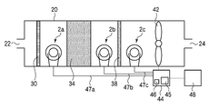
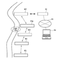
- FIG. 2 is a diagram showing the configuration of the atmospheric environment measuring apparatus according to the first embodiment.
- FIG. 3 is a diagram showing an outline of the atmospheric environment measurement system according to the first embodiment.
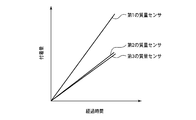
- FIG. 4 is a graph showing the change with time of the amount of substances adhering to each mass sensor when the adsorption capability of the first chemical filter is sufficient.
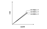
- FIG. 5 is a graph showing the change with time of the amount of substances attached to each mass sensor when no acidic gas is present in the atmosphere.
- FIG. 6 is a graph showing the change over time in the amount of substance attached to each mass sensor when the first chemical filter breaks through in the middle.
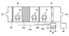
- FIG. 7 is a diagram showing the configuration of the atmospheric environment measuring apparatus according to the second embodiment.
- FIG. 8 is a diagram showing an outline of the atmospheric environment measurement system according to the second embodiment.
- FIG. 1 is a diagram illustrating an example of a mass sensor.
- FIG. 2 is a diagram showing an outline of the atmospheric environment measuring apparatus according to the present embodiment.
- a QCM (Quartz Crystal Microbalance) sensor 2 as shown in FIG. 1 can be used as the mass sensor.
- the QCM sensor is a mass sensor that uses a crystal resonator, and is a mass sensor that utilizes the property that when a substance adheres to the surface of the crystal oscillator, the resonance frequency changes according to the mass of the attached substance.
- the QCM sensor 2 includes a quartz substrate 10, a pair of electrodes 12a and 12b provided on both sides of the quartz substrate 10, terminals 16a and 16b connected to the electrodes 12a and 12b via lead wires 14a and 14b, and a terminal And a support plate 18 that supports 16a and 16b.
- the shape of the quartz substrate 10 is a substantially disk shape.
- the material of the electrodes (metal films) 12a and 12b for example, gold (Au) is used.
- the electrodes 12a and 12b and one ends of the lead wires 14a and 14b are respectively bonded by, for example, solder.
- a piezoelectric vibration element (quartz crystal resonator) 19 is formed by the quartz substrate 10 and the pair of electrodes 12a and 12b.
- the substrate 10 is not limited to a quartz substrate.
- a substrate made of a piezoelectric material can be widely used as the substrate 10.
- quartz substrate as the substrate 10 from the viewpoint of performing highly accurate measurement.
- the piezoelectric vibration element 19 oscillates at a constant resonance frequency.
- the resonance frequency of the piezoelectric vibration element 19 decreases according to the mass of the attached substance.
- the amount of change in the resonance frequency of the piezoelectric vibration element 19 is proportional to the amount of change in the mass of the substance attached to the surface of the piezoelectric vibration element 19.
- the casing 20 is formed with an intake port 22 and an exhaust port 24.
- the diameter of the casing 20 is about 20 mm, for example.
- the diameter of the intake port 22 and the diameter of the exhaust port 24 are set sufficiently small.
- the diameter of the intake port 22 is about 4 mm, for example.
- the diameter of the exhaust port 24 is about 4 mm, for example.
- the reason why the diameter of the intake port 22 and the diameter of the exhaust port 24 are set sufficiently small is that the air flows into the casing 20 from the intake port 22 and the exhaust port 24 even when the fan 42 is not operated. This is to prevent this.
- As the material of the casing 20 for example, stainless steel is used.
- the shape of the cross section of the casing 20, the intake port 22, and the exhaust port 24 is not particularly limited, and may be circular or square.
- a mesh 30 is arranged in the vicinity of the intake port 22 of the casing 20 in the vicinity of the intake port 22 of the casing 20, a mesh 30 is arranged.
- a material of the mesh 30 for example, stainless steel is used.
- the mesh 30 is for blocking sand and dust in the atmosphere.
- 1st mass sensor 2a is arranged in the latter part of the mesh 30 (downstream side).
- the first mass sensor 2a for example, the QCM sensor 2 described above with reference to FIG. 1 can be used.
- Various substances contained in the air that has passed through the mesh 30 may adhere to the surface of the first mass sensor 2a.
- a first chemical filter (first filter) 34 is disposed downstream (downstream) of the first QCM sensor 2a.
- the first chemical filter 34 for example, a chemical filter (trade name: TIOS (registered trademark) -A) manufactured by Takasago Thermal Engineering Co., Ltd. can be used. Such a chemical filter is capable of adsorbing an acid gas component.
- the thickness of the first chemical filter 34 is, for example, about 30 mm.
- the first chemical filter 34 is not necessarily able to completely remove the component of the acidic gas that is the object of adsorption.
- the first chemical filter 34 adsorbs an acid gas component according to the adsorption capacity.
- the chemical filter 34 that adsorbs acidic gas is used, but the present invention is not limited to this. What is necessary is just to select the kind of the chemical filter 34 suitably according to the objective.
- the second mass sensor 2b is disposed downstream (downstream) of the chemical filter 34.
- the QCM sensor 2 as described above with reference to FIG. 1 can be used.
- Various substances contained in the air after passing (transmitting) the chemical filter 34 may adhere to the surface of the second mass sensor 2b.
- a second chemical filter (second filter) 38 is disposed downstream (downstream) of the second mass sensor 2b.
- the second chemical filter 38 for example, a material capable of adsorbing an acid gas component similarly to the first chemical filter 34 is used.
- a chemical filter for example, a chemical filter (trade name: TIOS (registered trademark) -A) manufactured by Takasago Thermal Engineering Co., Ltd. is used in the same manner as the first chemical filter 34.
- a chemical filter having a thickness smaller than that of the first chemical filter 34 is used.
- the thickness of the second chemical filter 38 is, for example, about 10 mm. The reason why the second chemical filter 38 is thinner than the first chemical filter 34 is to reduce the cost.
- the first chemical filter 34 cannot always completely remove the component of the acidic gas that is the adsorption target.
- the second chemical filter 38 adsorbs the acid gas component contained in the air that has passed through the first chemical filter 34 according to the adsorption capacity.
- a third mass sensor 2c is disposed downstream (downstream) of the second chemical filter 38.
- the third mass sensor 2c for example, the QCM sensor 2 as described above with reference to FIG. 1 can be used.
- Various substances contained in the air after passing through the second chemical filter 38 may adhere to the surface of the third mass sensor 2c.
- a fan (air flow means, air flow means) 42 is disposed downstream (downstream) of the third mass sensor 2c.
- the fan 42 is for causing the air to flow from the intake port 22 to the exhaust port 24 (from the left side to the right side in FIG. 1).
- the atmospheric environment measuring apparatus is provided with a control device 44 that controls the entire atmospheric environment measuring apparatus.
- the control device 44 includes a control unit 45 including a QCM controller (not shown), a CPU (not shown), and the like, and a storage unit 46.
- the QCM controller is to resonate the QCM sensor by applying a predetermined voltage to the QCM sensor and measure the resonance frequency of the QCM sensor.
- a mixed signal microcontroller (model number: MSP430F2274) manufactured by Texas Instruments is used.
- the QCM controller is electrically connected to each of the mass sensors 2a to 2c via wirings 47a to 47c. More specifically, the QCM controller is electrically connected to the terminals 16a and 16b of the mass sensors 2a to 2c via the wires 47a to 47c, respectively.
- the storage unit 46 for example, a flash memory or the like can be used.
- the control unit 45 operates the fan 42 at a predetermined frequency and causes the atmosphere to flow from the intake port 22 toward the exhaust port 24.
- the control unit 45 operates the mass sensors 2a to 2c using the QCM controller, and measures the resonance frequency of the mass sensors 2a to 2c.
- control unit 45 stores the measurement data in the storage unit 46 together with the measurement time data.
- the measurement data includes data related to the resonance frequencies of the mass sensors 2a to 2c.
- the measurement time data is data indicating the measurement time when the measurement data is acquired.
- the control device 44 can be operated by a battery (not shown) such as a battery.
- the control device 44 can operate the mass sensors 2a to 2c and the fan 42 by a battery.
- the atmospheric environment measuring apparatus is provided with a transmission unit 48.
- the transmission unit 48 can transmit / receive measurement data and measurement time data to / from other atmospheric environment measurement devices.
- the transmission unit 48 is a processing device (monitoring device) 64 disposed at a location away from the atmospheric environment measuring device via a wireless base station 62 (see FIG. 3) and a network 63 (see FIG. 3) such as the Internet. Measurement data and measurement time data can be transmitted to (see FIG. 3).
- a wireless module (trade name: Ibex, Ibex) manufactured by Ards Corporation can be used.
- the transmission unit 48 can be operated by a battery such as a battery.
- Control unit 45 of control device 44 operates fan 42 intermittently at a predetermined frequency. Specifically, the control unit 45 applies a voltage to the fan 42 at a predetermined frequency, thereby rotating the fan 42 for a predetermined time.
- the frequency at which the fan 42 is operated is, for example, about once per hour.
- One operation time is, for example, about 1 minute.
- operation frequency and operation time of the fan 42 are not limited to this, and can be set as appropriate.
- the atmosphere flows in the casing 20 from the intake port 22 toward the exhaust port 24. Substances contained in the air can adhere to the surfaces of the mass sensors 2a to 2c.
- the air in the stage before passing through the first chemical filter 34 that is, the substance contained in the atmosphere, can adhere to the surface of the first mass sensor 2a.
- a substance contained in air at a stage after passing through the first chemical filter 34 may adhere to the surface of the second mass sensor 2b.
- a substance contained in air at a stage after passing through the second chemical filter 38 may adhere to the surface of the third mass sensor 2c.
- the measurement frequency of the resonance frequency of the mass sensors 2a to 2c is not limited to this, and can be set as appropriate.
- the control unit 45 operates each of the mass sensors 2a to 2c using a QCM controller (not shown) at a predetermined frequency. Specifically, the control unit 45 resonates the mass sensors 2a to 2c by applying a predetermined voltage to the mass sensors 2a to 2c using a QCM controller. Then, the control unit 45 measures the resonance frequency of the mass sensors 2a to 2c using the QCM controller.
- the frequency of measuring the resonance frequency of the mass sensors 2a to 2c is, for example, about once per hour.
- the control unit 45 stores the measurement data regarding the resonance frequency of the mass sensors 2a to 2c in the storage unit 46 together with the measurement time data.
- the transmission unit 48 transmits measurement data, measurement time data, and the like as described later.
- the first mass sensor 2a is provided in the front stage of the first chemical filter 34 that can adsorb the component of the acidic gas
- the second stage is provided in the rear stage of the first chemical filter 34.
- a mass sensor 2b is provided.
- the amount of change per unit time of the oscillation frequency of the first mass sensor 2a and the amount of change per unit time of the oscillation frequency of the second mass sensor 2b according to the concentration of the acidic gas contained in the atmosphere There is a difference between For this reason, according to this embodiment, based on the amount of change per unit time of the oscillation frequency of the first mass sensor 2a and the amount of change per unit time of the oscillation frequency of the second mass sensor 2b, It becomes possible to measure the degree or concentration of the acidic gas contained therein.
- a second chemical filter 38 capable of adsorbing acidic gas is provided at the subsequent stage of the second mass sensor 2b, and the third mass sensor 2c is disposed at the subsequent stage of the second chemical filter 38.
- the first chemical filter 34 cannot sufficiently adsorb the component of the acid gas, and therefore the surface of the second mass sensor 2b has the first The component of the acidic gas contained in the air which passed the chemical filter 34 may adhere.
- the substance contained in the air after the acidic gas component is adsorbed by the second chemical filter 38 may adhere to the third mass sensor 2c.
- concentration of the acidic gas contained in the air after passing the 1st chemical filter 34 the variation
- the adsorption capacity of the first chemical filter 34 has decreased based on the amount of change per unit time of the oscillation frequency of the first mass sensor 2a, the second mass sensor 2b, and the third mass sensor 2c. It is also possible to judge.
- the atmospheric environment measuring device can be driven by a battery.
- the atmospheric environment measuring apparatus since the atmospheric environment measuring apparatus according to the present embodiment has a simple configuration, it can be provided at low cost and there are few restrictions on the installation location. Therefore, a large number of the atmospheric environment measuring devices according to the present embodiment can be arranged at various locations without requiring a huge expense. Therefore, according to the present embodiment, it is possible to acquire data relating to the atmospheric environment over a wide range without requiring a large amount of cost.
- FIG. 3 is a diagram showing an outline of the atmospheric environment measurement system according to the present embodiment.
- the atmospheric environment measuring system includes atmospheric environment measuring devices 60a to 60e and a processing device (monitoring device) 64.
- the atmospheric environment measuring devices 60a to 60e for example, those similar to the atmospheric environment measuring device described above with reference to FIG. 2 can be used.
- the atmospheric environment measuring devices 60a to 60e are arranged at each measurement location.
- the atmospheric environment measuring devices 60a to 60e can perform wireless communication with each other via each transmission unit 48 (see FIG. 2).
- the atmospheric environment measuring devices 60a to 60e can perform wireless communication with each other without using an access point such as the base station 62 (ad hoc communication).
- At least one atmospheric environment measuring device among the atmospheric environment measuring devices 60 a to 60 e is arranged at a place where wireless communication with the wireless base station (access point) 62 is possible.
- the atmospheric environment measurement device 60a is arranged at a location where communication with the radio base station 62 is possible.
- the atmospheric environment measuring device 60 a can perform wireless communication with the wireless base station 62.
- the wireless base station 62 is connected to a network 63 such as the Internet.
- the processing device 64 is also connected to a network 63 such as the Internet.
- the processing device 64 for example, a personal computer in which a predetermined measurement program (monitoring program) or the like is installed can be used.
- the place where the processing device 64 is arranged may be any place that can be connected to the network 63. Therefore, the processing device 64 can be arranged at a location far from the atmospheric environment measuring devices 60a to 60e. For this reason, according to this embodiment, it becomes possible to measure atmospheric environment from a remote place.
- wireless communication is performed between the atmospheric environment measuring device 60a and the wireless base station 62, but wireless communication is not performed between the atmospheric environment measuring devices 60b to 60e and the wireless base station 62. explain.
- the atmospheric environment measurement devices 60a to 60e arranged at each measurement location acquire measurement data at a predetermined frequency.
- the measurement data measured by the atmospheric environment measuring devices 60a to 60e are collected in the atmospheric environment measuring device 60a. Specifically, measurement data, measurement time data, and identification data (identification information, ID number) of the atmospheric environment measurement device that acquired the measurement data are wirelessly communicated with each other between the atmospheric environment measurement devices 60a to 60e. To collect the atmospheric environment measurement device 60a.
- the atmospheric environment measuring device 60a transmits the measurement data, the measurement time data, and the identification data of the atmospheric environment measuring device that has acquired the measurement data to the processing device 64 via the radio base station 62 and the network 63.
- the processing device 64 measures (monitors) the atmospheric environment as described later based on the measurement data and measurement time data acquired by the atmospheric environment measurement devices 60a to 60e.
- measurement data acquired by the atmospheric environment measurement devices 60a to 60e arranged at each measurement location is transmitted to the processing device 64 via wireless communication or the network 63. Therefore, according to this embodiment, it is possible to arrange the atmospheric environment measuring devices 60a to 60e at various measurement locations and measure the atmospheric environment at a remote place.
- FIG. 4 is a graph showing changes over time in the amount of substances attached to the mass sensors 2a to 2c when the adsorption capability of the first chemical filter is sufficient.
- FIG. 4 is a graph showing the change with time of the amount of substances attached to the mass sensors 2a to 2c when no acidic gas is present in the atmosphere.
- FIG. 6 is a graph showing the change over time in the amount of substances attached to the mass sensors 2a to 2c when the first chemical filter 34 breaks through in the middle.
- the resonance frequency of the mass sensors 2a to 2c is measured at a predetermined frequency.
- the acquired measurement data is transmitted to the processing device 64 via the network 63 and the like together with the measurement time data and the identification data of the atmospheric environment measurement devices 60a to 60e that have performed the measurement.
- the processing device 64 is installed with a measurement program (monitoring program) for measuring (monitoring) the atmospheric environment as described above.
- the processing device 64 measures the atmospheric environment using a measurement program as follows.
- the processing device 64 can measure the degree of acid gas content in the atmosphere as follows, for example. .
- the processing device 64 obtains the amount of change per unit time of the resonance frequency of the first mass sensor 2a.
- the amount of change per unit time of the resonance frequency of the first mass sensor 2a is obtained based on measurement data about the resonance frequency of the first mass sensor 2a and measurement time data that is the time when the measurement was performed. Is possible.
- the processing device 64 obtains the amount of change per unit time of the resonance frequency of the second mass sensor 2b.
- the amount of change per unit time of the resonance frequency of the second mass sensor 2b is obtained based on the measurement data about the resonance frequency of the second mass sensor 2b and the measurement time data that is the time when the measurement was performed. Is possible.
- the amount of substances attached to the surfaces of the mass sensors 2a to 2c changes as shown in FIG. 4, for example. Since the second mass sensor 2b is disposed after the chemical filter 34 capable of adsorbing acid gas, the amount of substances attached to the surface of the first mass sensor 2a is reduced to the surface of the second mass sensor 2b. The amount of this substance increases with the concentration of the acidic gas contained in the atmosphere.
- the amount of change in the resonance frequency of each of the mass sensors 2a to 2c is proportional to the amount of change in the mass of the substance attached to the surfaces of the mass sensors 2a to 2c. Therefore, the difference between the amount of change per unit time of the resonance frequency of the first mass sensor 2a and the amount of change per unit time of the resonance frequency of the second mass sensor 2b is the concentration of acid gas contained in the atmosphere. Is proportional to
- reference data (teacher data) is prepared in advance.
- Such reference data is stored in a storage device (not shown) such as a hard disk drive (HDD) provided in the processing device 64.
- HDD hard disk drive
- Such reference data includes the difference between the amount of change in the resonance frequency of the first mass sensor 2a per unit time and the amount of change in the resonance frequency of the second mass sensor 2b per unit time for each concentration of acid gas. It is obtained by conducting an experiment or the like.
- the difference between the amount of change per unit time of the resonance frequency of the first mass sensor 2a and the amount of change per unit time of the resonance frequency of the second mass sensor 2b was obtained for each concentration of acid gas.
- the concentration of the acid gas can be determined.
- concentration of acidic gas was judged as an example was demonstrated here, it is not limited to judging a density
- the difference between the amount of change per unit time of the resonance frequency of the first mass sensor 2a and the amount of change per unit time of the resonance frequency of the second mass sensor 2b is included in the atmosphere. It is obtained in advance for each acid gas content (level). As the degree of acidic gas contained in the atmosphere, for example, level 1, level 2,.
- the difference between the amount of change per unit time of the resonance frequency of the first mass sensor 2a and the amount of change per unit time of the resonance frequency of the second mass sensor 2b is compared with the reference data, so that the air It is possible to determine the degree (level) of acid gas contained therein.
- the atmospheric environment measuring method it is possible to determine the degree of acid gas contained in the atmosphere.
- the atmospheric environment measuring devices 60a to 60e are arranged at each measurement location.
- the case where five atmospheric environment measuring devices are arranged will be described as an example.
- the number of atmospheric environment measuring devices is not limited to five, and is appropriately arranged at a location where the atmospheric environment should be measured. do it.
- the processing device 64 can issue a warning that acid gas is generated in the vicinity of the location where the atmospheric environment measuring device 60c is disposed.
- breakthrough of the first chemical filter 34 is determined as follows.
- the amount of change per unit time of the resonance frequency of the first mass sensor 2a is equal to the amount of change of the resonance frequency of the second mass sensor 2b per unit time.
- the amount of change per unit time of the resonance frequency of the first mass sensor 2a and the amount of change per unit time of the resonance frequency of the second mass sensor 2b are equal to each other. It cannot be determined that 34 has broken through.
- the change in the amount of substance attached to the surface of the first mass sensor 2a and the substance on the surface of the second mass sensor 2b This is because the change in the amount of adhesion is equal to each other.
- the breakthrough of the first chemical filter 34 is determined by using the measurement data of the third mass sensor 2c arranged at the subsequent stage of the second chemical filter 38.
- the amount of change in the resonance frequency of the first mass sensor 2a per unit time and the unit of the resonance frequency of the second mass sensor 2b The amount of change per time is equal to each other.
- the change in the amount of substances attached to the surface of the first mass sensor 2a and the second mass sensor 2b This is because the change in the amount of substances adhering to the surface is equal to each other.
- the amount of change per unit time of the resonance frequency of the third mass sensor 2c is It becomes smaller than the amount of change per unit time of the resonance frequency of the second mass sensors 2a, 2b.
- the reason why the change amount per unit time of the resonance frequency of the third mass sensor 2c is smaller than the change amount per unit time of the resonance frequency of the first and second mass sensors 2a and 2b is as follows. Is due to. That is, the deterioration of the chemical filter proceeds from the upstream side. At the stage where the first chemical filter 34 has broken through, the second chemical filter 38 has not broken through. The third mass sensor 2c is arranged at the rear stage of the second chemical filter 38 that has not been broken through. Therefore, as shown in FIG. 6, the change in the amount of substance attached to the surface of the third mass sensor 2 c is more than the change in the amount of substance attached to the surfaces of the first and second mass sensors 2 a and 2 b. small. For this reason, the amount of change per unit time of the resonance frequency of the third mass sensor 2c is smaller than the amount of change per unit time of the resonance frequency of the first and second mass sensors 2a and 2b.
- the first condition is that the amount of change per unit time of the resonance frequency of the first mass sensor 2a and the amount of change per unit time of the resonance frequency of the second mass sensor 2b are substantially equal to each other.
- the second condition is that the change amount per unit time of the resonance frequency of the third mass sensor 2c is smaller than the change amount per unit time of the resonance frequency of the second mass sensor 2b.
- the adsorption capability of the first chemical filter 34 is in a stage before the adsorption capability of the chemical filter 34 is completely lost. It may also be determined that has decreased.
- the amount of change per unit time of the resonance frequency of the second mass sensor 2b is It becomes smaller than the amount of change per unit time of the resonance frequency of one mass sensor 2a. This is because the acidic gas is adsorbed to some extent by the first chemical filter 34. In this case, the amount of change in the resonance frequency of the third mass sensor 2c per unit time is smaller than the amount of change in the resonance frequency of the second mass sensor 2b per unit time. This is because the acidic gas is adsorbed by the second chemical filter 38.
- the first condition is that the amount of change in the resonance frequency of the second mass sensor 2b per unit time is smaller than the amount of change in the resonance frequency of the first mass sensor 2a per unit time by a first predetermined value or more. is there.
- the second condition is that the amount of change per unit time of the resonance frequency of the second mass sensor 2b is larger than the amount of change per unit time of the resonance frequency of the third mass sensor 2c by a second predetermined value or more. is there.
- the degree of acid gas content in the atmosphere can be measured.
- the replacement frequency of the 1st chemical filter 34 is set. It is also possible to reduce it.
- FIG. 7 is a diagram showing the configuration of the atmospheric environment measuring apparatus according to the present embodiment.
- FIG. 8 is a diagram showing an outline of the atmospheric environment measurement system.
- the same components as those in the atmospheric environment measuring apparatus, the atmospheric environment measuring method, and the atmospheric environment measuring system according to the first embodiment shown in FIGS. 1 to 6 are denoted by the same reference numerals, and description thereof is omitted or simplified.
- the atmospheric environment measuring apparatus, the atmospheric environment measuring method, and the atmospheric environment measuring system according to the present embodiment use a basic gas as a detection target gas.
- a chemical filter capable of adsorbing basic gas is used as the first chemical filter 34a.
- a chemical filter for example, a chemical filter (trade name: TIOS (registered trademark) -B) manufactured by Takasago Thermal Engineering Co., Ltd. can be used.
- the second chemical filter 38a a chemical filter capable of adsorbing basic gas is used.
- a chemical filter for example, a chemical filter (trade name: TIOS (registered trademark) -B) manufactured by Takasago Thermal Engineering Co., Ltd. can be used. Similar to the first embodiment, the thickness of the second chemical filter 38a is set to be thinner than the thickness of the first chemical filter 34a.
- the atmospheric environment measuring device is formed.
- the atmospheric environment measurement method according to the present embodiment is substantially the same as the atmospheric environment measurement method according to the first embodiment, description thereof is omitted.
- the chemical filter capable of adsorbing the basic gas is used as the chemical filters 34a and 34b, the atmospheric environment can be measured using the basic gas as the detection target gas. Is possible.
- atmospheric environment measurement devices 60f to 60j are arranged along the river at each measurement location.
- the atmospheric environment measuring device 60f to 60j the atmospheric environment measuring device according to this embodiment described above with reference to FIG. 7 can be used.
- the processing device 64 can issue a warning that basic gas is generated in the vicinity of the place where the atmospheric environment measuring devices 60g and 60h are arranged.
- Amine gas is released from dead fish.
- the amine-based gas is a kind of basic gas. Therefore, according to the present embodiment, it is possible to indirectly detect a large amount of fish death or the like with a basic gas. If a large number of fish deaths are detected, it is possible to indirectly detect river pollution.
- the detection target gas is an acidic gas
- the detection target gas is a basic gas
- the detection target gas may be an organic gas.
- a chemical filter that can adsorb the organic gas may be used as the chemical filters 34 and 38.
- the chemical filter that can adsorb organic gas include a chemical filter (trade name: TIOS (registered trademark) -O) manufactured by Takasago Thermal Engineering Co., Ltd.
- the control unit 45 of the control device 44 of the atmospheric environment measurement apparatus may determine the degree or concentration of the detection target gas in the atmosphere.
Landscapes
- Physics & Mathematics (AREA)
- General Physics & Mathematics (AREA)
- Life Sciences & Earth Sciences (AREA)
- Health & Medical Sciences (AREA)
- General Health & Medical Sciences (AREA)
- Chemical & Material Sciences (AREA)
- Analytical Chemistry (AREA)
- Biochemistry (AREA)
- Immunology (AREA)
- Pathology (AREA)
- Molecular Biology (AREA)
- Biomedical Technology (AREA)
- Engineering & Computer Science (AREA)
- Acoustics & Sound (AREA)
- Sampling And Sample Adjustment (AREA)
Abstract
【課題】大気環境の測定を安価に実現し得る大気環境測定装置、大気環境測定方法及び大気環境測定システムを提供する。 【解決手段】ケーシング20内に配され、検出対象のガスの成分を吸着するフィルタ34と、吸気口22とフィルタとの間におけるケーシング内に配され、第1の圧電振動素子の表面に付着した物質の質量に応じて共振周波数が変化する第1の質量センサ2aと、フィルタの後段に配され、第2の圧電振動素子の表面に付着した物質の質量に応じて共振周波数が変化する第2の質量センサ2bと、ケーシング内における第2の質量センサの後段に配され、吸気口から排気口24に向かって大気を流動させるファン42とを有している。
Description
本発明は、大気環境測定装置、大気環境測定方法及び大気環境測定システムに関する。
安全な大気環境を実現するためには、大気環境の測定が極めて重要である。
また、様々な箇所において大気環境の測定を行えば、有害ガスの発生源等を特定することも可能である。
背景技術としては、例えば以下のようなものがある。
しかしながら、従来の大気環境測定装置は、大型であるため設置場所に制限があった。また、従来の大気環境測定装置は、高価であるため、費用的な観点から、様々な箇所に配置することは困難であった。このため、従来は、巨額の費用を投じることなく広範囲の大気環境を測定することは容易ではなかった。
本発明の目的は、大気環境の測定を安価に実現し得る大気環境測定装置、大気環境測定方法及び大気環境測定システムを提供することにある。
実施形態の一観点によれば、ケーシング内に配され、検出対象のガスの成分を吸着する第1のフィルタと、前記ケーシングの吸気口と前記第1のフィルタとの間における前記ケーシング内に配され、第1の圧電振動素子を有し、前記第1の圧電振動素子の表面に付着した物質の質量に応じて共振周波数が変化する第1の質量センサと、前記ケーシング内における前記第1のフィルタの後段に配され、第2の圧電振動素子を有し、前記第2の圧電振動素子の表面に付着した物質の質量に応じて共振周波数が変化する第2の質量センサと、前記ケーシング内における前記第2の質量センサの後段に配され、前記吸気口から前記ケーシングの排気口に向かって大気を流動させるファンとを有することを特徴とする大気環境測定装置が提供される。
実施形態の他の観点によれば、ケーシング内に配され、検出対象のガスの成分を吸着する第1のフィルタと、前記ケーシングの吸気口と前記第1のフィルタとの間における前記ケーシング内に配され、第1の圧電振動素子を有し、前記第1の圧電振動素子の表面に付着した物質の質量に応じて共振周波数が変化する第1の質量センサと、前記ケーシング内における前記第1のフィルタの後段に配され、第2の圧電振動素子を有し、前記第2の圧電振動素子の表面に付着した物質の質量に応じて共振周波数が変化する第2の質量センサと、前記ケーシング内における前記第2の質量センサの後段に配され、前記吸気口から前記ケーシングの排気口に向かって大気を流動させるファンと、前記第1の質量センサ及び前記第2の質量センサによる測定データを無線により伝送する伝送部とを有する大気環境測定装置と、前記大気環境測定装置から伝送される前記測定データを、ネットワークを介して取得し、取得した前記測定データに基づいて大気環境の測定を行う処理装置とを有することを特徴とする大気環境測定システムが提供される。
実施形態の更に他の観点によれば、ケーシング内に配され、検出対象のガスの成分を吸着する第1のフィルタと、前記ケーシングの吸気口と前記第1のフィルタとの間における前記ケーシング内に配され、第1の圧電振動素子を有し、前記第1の圧電振動素子の表面に付着した物質の質量に応じて共振周波数が変化する第1の質量センサと、前記ケーシング内における前記第1のフィルタの後段に配され、第2の圧電振動素子を有し、前記第2の圧電振動素子の表面に付着した物質の質量に応じて共振周波数が変化する第2の質量センサと、前記ケーシング内における前記第2の質量センサの後段に配され、前記吸気口から前記ケーシングの排気口に向かって大気を流動させるファンと、前記第1の質量センサ及び前記第2の質量センサによる測定データを無線により伝送する伝送部とを有する大気環境測定装置を用いた大気環境測定方法であって、前記第1の質量センサによる測定データと前記第2の質量センサによる測定データとに基づいて、大気中における前記検出対象のガスの含有の程度又は濃度を測定することを特徴とする大気環境測定方法が提供される。
開示の大気環境測定装置によれば、検出対象のガスの成分を吸着し得る第1のフィルタの前段に第1の質量センサが設けられており、第1のフィルタの後段に第2の質量センサが設けられている。このため、第1の質量センサには、検出対象のガスの成分の吸着が行われる前の段階の空気中に含まれる物質が付着し得る。一方、第2の質量センサには、第1のフィルタを通過した後の空気中に含まれる物質が付着し得る。従って、大気中に含まれる検出対象のガスの濃度に応じて、第1の質量センサの発振周波数の単位時間当たりの変化量と、第2の質量センサの発振周波数の単位時間当たりの変化量との間に差異が生じる。このため、第1の質量センサの発振周波数の単位時間当たりの変化量と、第2の質量センサの発振周波数の単位時間当たりの変化量とに基づいて、大気中における検出対象のガスの含有の程度又は濃度を測定することができる。
[第1実施形態]
第1実施形態による大気環境測定装置、大気環境測定方法、及び、大気環境測定システムについて図1乃至図6を用いて説明する。
第1実施形態による大気環境測定装置、大気環境測定方法、及び、大気環境測定システムについて図1乃至図6を用いて説明する。
(大気環境測定装置)
まず、本実施形態による大気環境測定装置を図1乃至図3を用いて説明する。図1は、質量センサの例を示す図である。図2は、本実施形態による大気環境測定装置の概略を示す図である。
まず、本実施形態による大気環境測定装置を図1乃至図3を用いて説明する。図1は、質量センサの例を示す図である。図2は、本実施形態による大気環境測定装置の概略を示す図である。
本実施形態において用いられる質量センサの例について図1を用いて説明する。
質量センサとしては、例えば図1に示すようなQCM(Quartz Crystal Microbalance)センサ2を用いることができる。QCMセンサとは、水晶振動子を用いた質量センサであり、水晶振動子の表面に物質が付着すると付着した物質の質量に応じて共振周波数が変化するという性質を利用した質量センサである。
QCMセンサ2は、水晶基板10と、水晶基板10の両面に設けられた一対の電極12a,12bと、リード線14a,14bを介して電極12a,12bに接続された端子16a,16bと、端子16a,16bを支持する支持板18とを有している。
水晶基板10の形状は略円盤状である。
電極(金属膜)12a,12bの材料としては、例えば金(Au)が用いられている。
電極12a,12bとリード線14a,14bの一端とは、それぞれ例えばはんだにより接着されている。
水晶基板10及び一対の電極12a,12bにより、圧電振動素子(水晶振動子)19が形成されている。
なお、ここでは、基板10として水晶基板を用いる場合を例に説明したが、基板10は、水晶基板に限定されるものではない。圧電材料の基板を、基板10として、広く用いることが可能である。
但し、高精度な測定を行う観点からは、基板10として、水晶基板を用いることが好ましい。
端子16a、16bを介して電極12a,12bに電圧を印加すると、圧電振動素子19は一定の共振周波数で発振する。圧電振動素子19の表面に物質が付着すると、付着した物質の質量に応じて圧電振動素子19の共振周波数が低下する。圧電振動素子19の共振周波数の変化量は、圧電振動素子19の表面に付着した物質の質量の変化量に比例する。
図1に示すようなQCMセンサ2は、例えば京セラ株式会社等により提供されている。
次に、本実施形態による大気環境測定装置の構成について図2を用いて説明する。
図2に示すように、ケーシング20には、吸気口22と排気口24が形成されている。ケーシング20の径は、例えば20mm程度とする。吸気口22の口径及び排気口24の口径は、十分に小さく設定されている。吸気口22の口径は、例えば4mm程度とする。排気口24の口径は、例えば4mm程度とする。吸気口22の口径及び排気口24の口径を十分に小さく設定しているのは、ファン42を動作させていないにもかかわらず、大気が吸気口22や排気口24からケーシング20内に流入するのを防止するためである。ケーシング20の材料としては、例えばステンレスが用いられている。
なお、ケーシング20,吸気口22及び排気口24の断面の形状は、特に限定されるものではなく、円型であっても角型であってもよい。
ケーシング20の吸気口22の近傍には、メッシュ30が配されている。メッシュ30の材料としては、例えばステンレスを用いる。メッシュ30は、大気中の砂や埃等を遮断するためのものである。
メッシュ30の後段(下流側)には、第1の質量センサ2aが配されている。第1の質量センサ2aとしては、例えば図1を用いて上述したようなQCMセンサ2を用いることができる。第1の質量センサ2aの表面には、メッシュ30を通り抜けた空気中に含まれる様々な物質が付着し得る。
第1のQCMセンサ2aの後段(下流側)には、第1のケミカルフィルタ(第1のフィルタ)34が配されている。第1のケミカルフィルタ34としては、例えば高砂熱学工業株式会社製のケミカルフィルタ(商品名:TIOS(商標登録)-A)を用いることができる。かかるケミカルフィルタは、酸性ガスの成分を吸着し得るものである。第1のケミカルフィルタ34の厚さは、例えば30mm程度である。
なお、第1のケミカルフィルタ34は、吸着対象である酸性ガスの成分を必ずしも完全に除去し得るとは限らない。第1のケミカルフィルタ34は、吸着能力に応じて酸性ガスの成分を吸着する。
なお、本実施形態では、ケミカルフィルタ34として酸性ガスを吸着するものを用いたが、これに限定されるものではない。目的に応じてケミカルフィルタ34の種類を適宜選択すればよい。
ケミカルフィルタ34の後段(下流側)には、第2の質量センサ2bが配されている。第2の質量センサ2bとしては、例えば図1を用いて上述したようなQCMセンサ2を用いることができる。第2の質量センサ2bの表面には、ケミカルフィルタ34を通過(透過)した後の空気中に含まれる様々な物質が付着し得る。
第2の質量センサ2bの後段(下流側)には、第2のケミカルフィルタ(第2のフィルタ)38が配されている。
第2のケミカルフィルタ38としては、例えば第1のケミカルフィルタ34と同様に酸性ガスの成分を吸着し得るものを用いる。ここでは、第2のケミカルフィルタ38として、第1のケミカルフィルタ34と同様に、例えば高砂熱学工業株式会社製のケミカルフィルタ(商品名:TIOS(商標登録)-A)を用いる。第2のケミカルフィルタ38としては、第1のケミカルフィルタ34より厚さの薄いケミカルフィルタが用いられている。第2のケミカルフィルタ38の厚さは、例えば10mm程度である。第2のケミカルフィルタ38として第1のケミカルフィルタ34より薄いものを用いているのは、コストを低減するためである。
上述したように、第1のケミカルフィルタ34は、吸着対象である酸性ガスの成分を必ずしも完全に除去し得るとは限らない。第2のケミカルフィルタ38は、第1のケミカルフィルタ34を通過した空気中に含まれる酸性ガスの成分を、吸着能力に応じて吸着する。
第2のケミカルフィルタ38の後段(下流側)には、第3の質量センサ2cが配されている。第3の質量センサ2cとしては、例えば図1を用いて上述したようなQCMセンサ2を用いることができる。第3の質量センサ2cの表面には、第2のケミカルフィルタ38を通過した後の空気中に含まれる様々な物質が付着し得る。
第3の質量センサ2cの後段(下流側)には、ファン(空気流動手段、大気流動手段)42が配されている。ファン42は、吸気口22から排気口24(図1中の紙面左側から右側)に向かって大気を流動させるためのものである。
本実施形態による大気環境測定装置には、大気環境測定装置全体を制御する制御装置44が設けられている。制御装置44は、QCMコントローラ(図示せず)、CPU(図示せず)等を含む制御部45と、記憶部46とを有している。
QCMコントローラとは、QCMセンサに所定の電圧を印加することによりQCMセンサを共振させ、QCMセンサの共振周波数を測定するものである。QCMコントローラには、例えばテキサスインスツルメンツ社製のミックスド・シグナル・マイクロコントローラ(型番:MSP430F2274)等が用いられている。
QCMコントローラは、配線47a~47cを介して、各々の質量センサ2a~2cに電気的に接続されている。より具体的には、QCMコントローラは、配線47a~47cを介して各々の質量センサ2a~2cの端子16a,16bにそれぞれ電気的に接続されている。
記憶部46としては、例えばフラッシュメモリ等を用いることができる。
制御部45は、所定の頻度で、ファン42を動作させ、吸気口22から排気口24に向かって大気を流動させる。また、制御部45は、QCMコントローラを用いて質量センサ2a~2cを動作させ、質量センサ2a~2cの共振周波数を測定する。
また、制御部45は、測定データを測定時刻データと共に記憶部46に記憶させる。測定データは、質量センサ2a~2cのそれぞれの共振周波数に関するデータを含むものである。測定時刻データは、測定データを取得した測定時刻を示すデータである。
制御装置44は、電池等のバッテリー(図示せず)により動作させることが可能である。制御装置44は、バッテリーにより、質量センサ2a~2cやファン42を動作させ得る。
また、本実施形態による大気環境測定装置には、伝送部48が設けられている。
伝送部48は、他の大気環境測定装置との間で、測定データ及び測定時刻データを互いに送受信することが可能である。
また、伝送部48は、無線基地局62(図3参照)及びインターネット等のネットワーク63(図3参照)を介して、大気環境測定装置から離れた箇所に配された処理装置(監視装置)64(図3参照)に測定データ及び測定時刻データを送信することが可能である。伝送部48としては、例えばアーズ株式会社製の無線モジュール(商品名:Ibex、アイベックス)等を用いることができる。
伝送部48は、電池等のバッテリーにより動作させることが可能である。
次に、本実施形態による大気環境測定装置の動作について説明する。
制御装置44の制御部45は、所定の頻度で、ファン42を間欠的に動作させる。具体的には、制御部45は、所定の頻度で、ファン42に電圧を印加し、これによりファン42を所定時間だけ回転させる。ファン42を動作させる頻度は、例えば1時間に1回程度とする。1回の動作時間は、例えば1分間程度とする。
なお、ファン42の動作頻度及び動作時間は、これに限定されるものではなく、適宜設定することができる。
ファン42を動作させると、吸気口22から排気口24に向かってケーシング20内を大気が流動する。質量センサ2a~2cの表面には、空気中に含まれる物質が付着し得る。
第1の質量センサ2aの表面には、第1のケミカルフィルタ34を通過する前の段階の空気、即ち大気中に含まれる物質が付着し得る。第2の質量センサ2bの表面には、第1のケミカルフィルタ34を通過した後の段階の空気中に含まれる物質が付着し得る。第3の質量センサ2cの表面には、第2のケミカルフィルタ38を通過した後の段階の空気中に含まれる物質が付着し得る。
なお、質量センサ2a~2cの共振周波数の測定頻度は、これに限定されるものではなく、適宜設定することができる。
制御部45は、所定の頻度で、QCMコントローラ(図示せず)を用いて各々の質量センサ2a~2cを動作させる。具体的には、制御部45は、QCMコントローラを用いて質量センサ2a~2cに所定の電圧を印加することにより、質量センサ2a~2cを共振させる。そして、制御部45は、質量センサ2a~2cの共振周波数を、QCMコントローラを用いて測定する。質量センサ2a~2cの共振周波数を測定する頻度は、例えば1時間に1回程度とする。
制御部45は、質量センサ2a~2cの共振周波数に関する測定データを、測定時刻データと共に記憶部46に記憶する。
伝送部48は、測定データ及び測定時刻データ等の伝送を、後述するようにして行う。
このように、本実施形態では、酸性ガスの成分を吸着し得る第1のケミカルフィルタ34の前段に第1の質量センサ2aが設けられており、第1のケミカルフィルタ34の後段に第2の質量センサ2bが設けられている。このため、第1の質量センサ2aには、酸性ガスの成分の吸着が行われる前の段階の空気中に含まれる物質が付着し得る。一方、第2の質量センサ2bには、第1のケミカルフィルタ34を通過した後の空気中に含まれる物質が付着し得る。従って、大気中に含まれる酸性ガスの濃度に応じて、第1の質量センサ2aの発振周波数の単位時間当たりの変化量と、第2の質量センサ2bの発振周波数の単位時間当たりの変化量との間に差異が生じる。このため、本実施形態によれば、第1の質量センサ2aの発振周波数の単位時間当たりの変化量と、第2の質量センサ2bの発振周波数の単位時間当たりの変化量とに基づいて、大気中に含まれる酸性ガスの含有の程度又は濃度を測定することが可能となる。
また、本実施形態では、第2の質量センサ2bの後段に酸性ガスを吸着し得る第2のケミカルフィルタ38が設けられており、第2のケミカルフィルタ38の後段に第3の質量センサ2cが設けられている。第1のケミカルフィルタ34の吸着能力が低下した場合には、第1のケミカルフィルタ34が酸性ガスの成分を十分に吸着し得ないため、第2の質量センサ2bの表面には、第1のケミカルフィルタ34を通過した空気中に含まれる酸性ガスの成分が付着し得る。一方、第3の質量センサ2cには、第2のケミカルフィルタ38により酸性ガスの成分が吸着された後の空気中に含まれる物質が付着し得る。このため、第1のケミカルフィルタ34を通過した後の空気中に含まれる酸性ガスの濃度に応じて、第2の質量センサ2bの発振周波数の単位時間当たりの変化量と、第3の質量センサ2cの発振周波数の単位時間当たりの変化量との間に差異が生じる。このため、第1の質量センサ2a、第2の質量センサ2b及び第3の質量センサ2cの発振周波数の単位時間当たりの変化量に基づいて、第1のケミカルフィルタ34の吸着能力が低下したことを判断することも可能である。
また、本実施形態による大気環境測定装置は、バッテリーにより駆動することが可能である。また、本実施形態による大気環境測定装置は、簡便な構成であるため、安価に提供することができ、設置場所の制限も少ない。従って、本実施形態による大気環境測定装置は、巨額の費用を要することなく、様々な箇所に多数配置することが可能である。従って、本実施形態によれば、巨額の費用を要することなく、大気環境に関するデータを広範囲に亘って取得することが可能となる。
(大気環境測定システム)
本実施形態による大気環境測定装置を用いた大気環境測定システムについて図2及び図3を用いて説明する。図3は、本実施形態による大気環境測定システムの概略を示す図である。
本実施形態による大気環境測定装置を用いた大気環境測定システムについて図2及び図3を用いて説明する。図3は、本実施形態による大気環境測定システムの概略を示す図である。
図3に示すように、本実施形態による大気環境測定システムは、大気環境測定装置60a~60eと、処理装置(監視装置)64とを有している。
大気環境測定装置60a~60eとしては、例えば図2を用いて上述した大気環境測定装置と同様のものを用いることができる。大気環境測定装置60a~60eは、各測定箇所に配される。
大気環境測定装置60a~60eは、各々の伝送部48(図2参照)を介して、相互に無線通信を行うことが可能である。大気環境測定装置60a~60eは、基地局62等のアクセスポイントを介することなく、相互に無線通信を行い得る(アドホック通信)。
大気環境測定装置60a~60eのうちの少なくとも1台の大気環境測定装置は、無線基地局(アクセスポイント)62との間で無線通信が可能な箇所に配される。ここでは、少なくとも大気環境測定装置60aを、無線基地局62との間で通信可能な箇所に配す場合を例に説明する。大気環境測定装置60aは、無線基地局62との間で無線通信を行い得る。
無線基地局62は、インターネット等のネットワーク63に接続されている。
処理装置64も、インターネット等のネットワーク63に接続されている。
処理装置64としては、例えば、所定の測定プログラム(監視プログラム)等がインストールされたパーソナルコンピュータを用いることができる。処理装置64が配される箇所は、ネットワーク63に接続可能な箇所であればよい。従って、処理装置64は、大気環境測定装置60a~60eから遠く離れた箇所に配することが可能である。このため、本実施形態によれば、遠隔地から大気環境を測定することが可能となる。
次に、本実施形態による大気環境測定システムの動作について図3を用いて説明する。
なお、ここでは、大気環境測定装置60aと無線基地局62との間で無線通信を行う一方、大気環境測定装置60b~60eと無線基地局62との間では無線通信を行わない場合を例に説明する。
各測定箇所に配された大気環境測定装置60a~60eは、上述したように、所定の頻度で測定データを取得する。
各大気環境測定装置60a~60eにより測定された測定データは、大気環境測定装置60aに集約される。具体的には、測定データ、測定時刻データ、及び、当該測定データを取得した大気環境測定装置の識別データ(識別情報、ID番号)を、各大気環境測定装置60a~60e同士で相互に無線通信を行うことにより、大気環境測定装置60aに集約する。
大気環境測定装置60aは、測定データ、測定時刻データ、及び、当該測定データを取得した大気環境測定装置の識別データを、無線基地局62及びネットワーク63を介して、処理装置64に伝送する。
処理装置64は、各大気環境測定装置60a~60eにより取得された測定データ及び測定時刻データに基づいて、後述するようにして、大気環境の測定(監視)を行う。
このように、本実施形態では、各測定箇所に配された大気環境測定装置60a~60eにより取得された測定データ等が、無線通信やネットワーク63を介して処理装置64に伝送される。従って、本実施形態によれば、様々な測定箇所に大気環境測定装置60a~60eを配し、遠隔地で大気環境を測定することが可能となる。
(大気環境測定方法)
本実施形態による大気環境測定装置を用いた大気環境測定方法について図3乃至図6を用いて説明する。図4は、第1のケミカルフィルタの吸着能力が十分な場合における、各々の質量センサ2a~2cへの物質の付着量の経時変化を示すグラフである。図4は、大気中に酸性ガスが存在しない場合における、各々の質量センサ2a~2cへの物質の付着量の経時変化を示すグラフである。図6は、第1のケミカルフィルタ34が途中で破過した場合における、各々の質量センサ2a~2cへの物質の付着量の経時変化を示すグラフである。
本実施形態による大気環境測定装置を用いた大気環境測定方法について図3乃至図6を用いて説明する。図4は、第1のケミカルフィルタの吸着能力が十分な場合における、各々の質量センサ2a~2cへの物質の付着量の経時変化を示すグラフである。図4は、大気中に酸性ガスが存在しない場合における、各々の質量センサ2a~2cへの物質の付着量の経時変化を示すグラフである。図6は、第1のケミカルフィルタ34が途中で破過した場合における、各々の質量センサ2a~2cへの物質の付着量の経時変化を示すグラフである。
まず、上述したように、各々の大気環境測定装置60a~60eにおいて、所定の頻度で、質量センサ2a~2cの共振周波数の測定が行われる。取得された測定データは、測定時刻データ及び測定を行った大気環境測定装置60a~60eの識別データと共に、ネットワーク63等を介して処理装置64へ伝送される。
処理装置64には、上述したように、大気環境の測定(監視)を行う測定プログラム(監視プログラム)がインストールされている。処理装置64は、測定プログラムを用いて、以下のようにして大気環境の測定を行う。
処理装置64は、第1の質量センサ2aによる測定データと第2の質量センサ2bによる測定データとに基づいて、例えば以下のようにして大気中の酸性ガスの含有の程度を測定することができる。
即ち、処理装置64は、第1の質量センサ2aの共振周波数の単位時間当たりの変化量を求める。第1の質量センサ2aの共振周波数の単位時間当たりの変化量は、第1の質量センサ2aの共振周波数についての測定データと、測定を行った時刻である測定時刻データとに基づいて、求めることが可能である。
また、処理装置64は、第2の質量センサ2bの共振周波数の単位時間当たりの変化量を求める。第2の質量センサ2bの共振周波数の単位時間当たりの変化量は、第2の質量センサ2bの共振周波数についての測定データと、測定を行った時刻である測定時刻データとに基づいて、求めることが可能である。
第1のケミカルフィルタ34の吸着能力が十分な場合には、各々の質量センサ2a~2cの表面への物質の付着量は、例えば図4のように変化する。第2の質量センサ2bは酸性ガスを吸着し得るケミカルフィルタ34の後段に配されているため、第1の質量センサ2aの表面への物質の付着量は、第2の質量センサ2bの表面への物質の付着量に対して、大気中に含まれる酸性ガスの濃度の分だけ大きくなる。
上述したように、各々の質量センサ2a~2cの共振周波数の変化量は、質量センサ2a~2cの表面に付着した物質の質量の変化量に比例する。従って、第1の質量センサ2aの共振周波数の単位時間当たりの変化量と、第2の質量センサ2bの共振周波数の単位時間当たりの変化量との差は、大気中に含まれる酸性ガスの濃度に比例する。
しかし、第1の質量センサ2aの共振周波数の単位時間当たりの変化量と、第2の質量センサ2bの共振周波数の単位時間当たりの変化量との差から、大気中に含まれる酸性ガスの濃度を計算により求めるのは必ずしも容易ではない。
そこで、本実施形態では、予め参照データ(教師データ)を準備しておく。かかる参照データは、処理装置64内に設けられたハードディスクドライブ(HDD)等の記憶装置(図示せず)に記憶されている。
かかる参照データは、第1の質量センサ2aの共振周波数の単位時間当たりの変化量と、第2の質量センサ2bの共振周波数の単位時間当たりの変化量との差を、酸性ガスの濃度毎に実験等を行うことにより求めたものである。
従って、第1の質量センサ2aの共振周波数の単位時間当たりの変化量と、第2の質量センサ2bの共振周波数の単位時間当たりの変化量との差を、酸性ガスの濃度毎に求められた参照データと対比することにより、酸性ガスの濃度を判断することが可能である。
なお、ここでは、酸性ガスの濃度を判断する場合を例に説明したが、濃度を判断することに限定されるものではない。大気中に含まれる酸性ガスの程度を判断する際に広く適用可能である。
例えば、参照データとして、第1の質量センサ2aの共振周波数の単位時間当たりの変化量と、第2の質量センサ2bの共振周波数の単位時間当たりの変化量との差を、大気中に含まれる酸性ガスの含有の程度(レベル)毎に予め求めておく。大気中に含まれる酸性ガスの程度としては、例えば、レベル1,レベル2,・・・・等が考えられる。
そして、第1の質量センサ2aの共振周波数の単位時間当たりの変化量と、第2の質量センサ2bの共振周波数の単位時間当たりの変化量との差を、参照データと対比することにより、空気中に含まれる酸性ガスの程度(レベル)を求めることが可能である。
このようにして、本実施形態による大気環境測定方法によれば、大気中に含まれる酸性ガスの程度を求めることが可能である。
また、本実施形態では、以下のようにして酸性ガスの発生場所等を特定することも可能である。
即ち、本実施形態では、各測定箇所に大気環境測定装置60a~60eがそれぞれ配される。
なお、ここでは、5台の大気環境測定装置を配する場合を例に説明するが、大気環境測定装置の数は5台に限定されるものではなく、大気環境を測定すべき箇所に適宜配置すればよい。
例えば、大気環境測定装置60cにより得られた測定データにおいては、大気中に含まれる酸性ガスの程度が比較的高かったとする。
一方、大気環境測定装置60a、60b、60d、60eにより得られた測定データにおいては、大気中に含まれる酸性ガスの程度が、比較的低かったとする。
この場合には、大気環境測定装置60cの近傍において酸性ガスが発生している可能性があると判断することが可能である。
例えば、大気環境測定装置60a~60eが、火山の各箇所に配されている場合には、当該火山のうちの大気環境測定装置60cが配されている箇所の近傍において酸性ガスが発生していると判断することができる。この場合、処理装置64は、大気環境測定装置60cが配されている箇所の近傍において酸性ガスが発生している旨の警報を発することが可能である。
このように、本実施形態によれば、酸性ガスの発生場所の特定等に資することができる。
ところで、長期間に亘ってケミカルフィルタを使い続けた場合には、ケミカルフィルタ吸着能力が低下する。ケミカルフィルタが寿命に達することは、破過と称される。
本実施形態による大気環境測定方法では、以下のようにして、第1のケミカルフィルタ34の破過を判断する。
第1のケミカルフィルタ34が破過に至った場合には、大気中の酸性ガスが第1のケミカルフィルタ34により吸着されない。このため、第1の質量センサ2aの共振周波数の単位時間当たりの変化量と、第2の質量センサ2bの共振周波数の単位時間当たりの変化量とは、互いに等しくなる。
しかし、第1の質量センサ2aの共振周波数の単位時間当たりの変化量と、第2の質量センサ2bの共振周波数の単位時間当たりの変化量が互いに等しくなったことのみにより、第1のケミカルフィルタ34が破過に至ったと判断することはできない。大気中に酸性ガスが含まれていない場合には、図5に示すように、第1の質量センサ2aの表面への物質の付着量の変化と、第2の質量センサ2bの表面への物質の付着量の変化とが、互いに等しくなるためである。
そこで、本実施形態では、第2のケミカルフィルタ38の後段に配された第3の質量センサ2cの測定データを用いることにより、第1のケミカルフィルタ34の破過を判断する。
第1のケミカルフィルタ34が破過に至った場合には、上述したように、第1の質量センサ2aの共振周波数の単位時間当たりの変化量と、第2の質量センサ2bの共振周波数の単位時間当たりの変化量とは、互いに等しくなる。図6に示すように、第2のケミカルフィルタ38が破過に達した時刻tより後においては、第1の質量センサ2aの表面への物質の付着量の変化と、第2の質量センサ2bの表面への物質の付着量の変化とが互いに等しくなるためである。
第1のケミカルフィルタ34が破過に至った場合において、大気中に酸性ガスが含まれている場合には、第3の質量センサ2cの共振周波数の単位時間当たりの変化量は、第1及び第2の質量センサ2a、2bの共振周波数の単位時間当たりの変化量より小さくなる。
第3の質量センサ2cの共振周波数の単位時間当たりの変化量が、第1及び第2の質量センサ2a、2bの共振周波数の単位時間当たりの変化量より小さくなるのは、以下のような理由によるものである。即ち、ケミカルフィルタの劣化は上流側から進行する。第1のケミカルフィルタ34が破過に至った段階では、第2のケミカルフィルタ38は破過に至っていない。第3の質量センサ2cは、破過に至っていない第2のケミカルフィルタ38の後段に配されている。このため、図6に示すように、第3の質量センサ2cの表面への物質の付着量の変化は、第1及び第2の質量センサ2a、2bの表面への物質の付着量の変化より小さい。このため、第3の質量センサ2cの共振周波数の単位時間当たりの変化量は、第1及び第2の質量センサ2a、2bの共振周波数の単位時間当たりの変化量より小さくなる。
従って、このような場合には、第1のケミカルフィルタ34が破過に至ったと判断することができる。
即ち、以下のような第1の条件と第2の条件のいずれをも満たす場合には、第1のケミカルフィルタ34が破過に至ったと判断することができる。第1の条件は、第1の質量センサ2aの共振周波数の単位時間当たりの変化量と、第2の質量センサ2bの共振周波数の単位時間当たりの変化量とは、互いにほぼ等しいことである。第2の条件は、第3の質量センサ2cの共振周波数の単位時間当たりの変化量が、第2の質量センサ2bの共振周波数の単位時間当たりの変化量より所定値以上小さいことである。
なお、ここでは、第1のケミカルフィルタ34が破過に至った場合を例に説明したが、ケミカルフィルタ34の吸着能力が完全に失われる前の段階において、第1のケミカルフィルタ34の吸着能力が低下したことを判断するようにしてもよい。
第1のケミカルフィルタ34の吸着能力が完全に失われる前の段階において、大気中に酸性ガスが含まれている場合、第2の質量センサ2bの共振周波数の単位時間当たりの変化量は、第1の質量センサ2aの共振周波数の単位時間当たりの変化量より小さくなる。第1のケミカルフィルタ34により酸性ガスがある程度吸着されるためである。また、この場合には、第3の質量センサ2cの共振周波数の単位時間当たりの変化量は、第2の質量センサ2bの共振周波数の単位時間当たりの変化量より小さくなる。第2のケミカルフィルタ38により酸性ガスが吸着されるためである。
従って、以下のような第1の条件と第2の条件のいずれをも満たす場合には、第1のケミカルフィルタ34の吸着能力がある程度低くなったと判断することが可能である。第1の条件は、第2の質量センサ2bの共振周波数の単位時間当たりの変化量が、第1の質量センサ2aの共振周波数の単位時間当たりの変化量より第1の所定値以上小さいことである。第2の条件は、第2の質量センサ2bの共振周波数の単位時間当たりの変化量が、第3の質量センサ2cの共振周波数の単位時間当たりの変化量より第2の所定値以上大きいことである。
このように、本実施形態によれば、第1のケミカルフィルタ34の吸着能力の低下を判断することが可能である。
このように、本実施形態によれば、大気中における酸性ガスの含有の程度を測定することができる。
また、本実施形態によれば、第1のケミカルフィルタ34の吸着能力の低下や破過を判断することができるため、誤測定等を防止することができる。
また、本実施形態によれば、第1のケミカルフィルタ34の吸着能力の低下や破過に応じて第1のケミカルフィルタ34の交換を行えばよいため、第1のケミカルフィルタ34の交換頻度を少なくすることも可能である。
[第2実施形態]
第2実施形態による大気環境測定装置、大気環境測定方法及び大気環境測定システムについて図7を用いて説明する。図7は、本実施形態による大気環境測定装置の構成を示す図である。図8は、大気環境測定システムの概略を示す図である。図1乃至図6に示す第1実施形態による大気環境測定装置、大気環境測定方法及び大気環境測定システムと同一の構成要素には、同一の符号を付して説明を省略または簡潔にする。
第2実施形態による大気環境測定装置、大気環境測定方法及び大気環境測定システムについて図7を用いて説明する。図7は、本実施形態による大気環境測定装置の構成を示す図である。図8は、大気環境測定システムの概略を示す図である。図1乃至図6に示す第1実施形態による大気環境測定装置、大気環境測定方法及び大気環境測定システムと同一の構成要素には、同一の符号を付して説明を省略または簡潔にする。
本実施形態による大気環境測定装置、大気環境測定方法及び大気環境測定システムは、検出対象のガスを塩基性ガスとしたものである。
まず、本実施形態による大気環境測定装置について図7を用いて説明する。
本実施形態による大気環境測定装置では、第1のケミカルフィルタ34aとして、塩基性ガスを吸着し得るケミカルフィルタが用いられている。かかるケミカルフィルタとしては、例えば高砂熱学工業社製のケミカルフィルタ(商品名:TIOS(商標登録)-B)等を用いることができる。
また、第2のケミカルフィルタ38aとしても、塩基性ガスを吸着し得るケミカルフィルタが用いられている。かかるケミカルフィルタとしても、例えば高砂熱学工業社製のケミカルフィルタ(商品名:TIOS(商標登録)-B)等を用いることができる。第2のケミカルフィルタ38aの厚さは、第1実施形態と同様に、第1のケミカルフィルタ34aの厚さより薄く設定されている。
このようにして、本実施形態による大気環境測定装置が形成されている。
本実施形態による大気環境測定方法は、第1実施形態による大気環境測定方法とほぼ同様であるので、説明を省略する。
このように、本実施形態によれば、ケミカルフィルタ34a、34bとして塩基性ガスを吸着し得るケミカルフィルタが用いられているため、塩基性ガスを検出対象のガスとして大気環境の測定を行うことが可能である。
次に、本実施形態による大気環境測定システムについて図8を用いて説明する。
図8に示すように、大気環境測定装置60f~60jが河川に沿って各測定箇所に配される。
大気環境測定装置60f~60jとしては、図7を用いて上述した本実施形態による大気環境測定装置を用いることができる。
例えば、大気環境測定装置60g、60hにより得られた測定データにおいては、大気中に含まれる塩基性ガスの程度が比較的高かったとする。
一方、大気環境測定装置60f、60i、60jにより得られた測定データにおいては、大気中に含まれる塩基性ガスの程度が、比較的低かったとする。
この場合には、例えば大気環境測定装置60g、60hが配された箇所の近傍において塩基性ガスが発生している(異常発生)と判断することが可能である。この場合には、処理装置64は、大気環境測定装置60g,60hが配されている箇所の近傍において塩基性ガスが発生している旨の警報を発することが可能である。
死んだ魚からは、アミン系ガスが放出される。アミン系ガスは、塩基性ガスの一種である。従って、本実施形態によれば、魚の大量死等を塩基性ガスにより間接的に検出することが可能である。魚の大量死等を検出すれば、河川の汚染等を間接的に検出することが可能である。
このように、本実施形態によれば、塩基性ガスの発生箇所の特定等に資することができ、ひいては、河川等の汚染源等の特定に資することもできる。
[変形実施形態]
上記実施形態に限らず種々の変形が可能である。
上記実施形態に限らず種々の変形が可能である。
例えば、第1実施形態では、検出対象のガスが酸性ガスである場合を例に説明し、第2実施形態では、検出対象のガスが塩基性ガスである場合を例に説明したが、これに限定されるものではない。例えば、検出対象のガスが有機ガスであってもよい。有機ガスを検出対象のガスとする場合には、ケミカルフィルタ34,38として、有機ガスを吸着し得るケミカルフィルタを用いればよい。有機ガスを吸着し得るケミカルフィルタとしては、例えば、高砂熱学工業社製のケミカルフィルタ(商品名:TIOS(商標登録)-O)を挙げることができる。
また、上記実施形態では、検出対象のガスが大気中に含まれている程度又は濃度を、処理装置64を用いて判断する場合を例に説明したが、これに限定されるものではない。例えば、大気環境測定装置の制御装置44の制御部45により、検出対象のガスが大気中に含まれている程度又は濃度を判断するようにしてもよい。
2,2a~2c…質量センサ
10…水晶基板
12a,12b…電極
14a,14b…リード線
16a,16b…端子
18…支持板
19…圧電振動子
20…ケーシング
22…吸気口
24…排気口
30…メッシュ
34,34a…ケミカルフィルタ
38,38a…ケミカルフィルタ
42…ファン
44…制御装置
45…制御部
46…記憶部
47a~47c…配線
48…伝送部
60a~60j…大気環境測定装置
62…無線基地局
63…ネットワーク
64…処理装置
10…水晶基板
12a,12b…電極
14a,14b…リード線
16a,16b…端子
18…支持板
19…圧電振動子
20…ケーシング
22…吸気口
24…排気口
30…メッシュ
34,34a…ケミカルフィルタ
38,38a…ケミカルフィルタ
42…ファン
44…制御装置
45…制御部
46…記憶部
47a~47c…配線
48…伝送部
60a~60j…大気環境測定装置
62…無線基地局
63…ネットワーク
64…処理装置
Claims (11)
- ケーシング内に配され、検出対象のガスの成分を吸着する第1のフィルタと、
前記ケーシングの吸気口と前記第1のフィルタとの間における前記ケーシング内に配され、第1の圧電振動素子を有し、前記第1の圧電振動素子の表面に付着した物質の質量に応じて共振周波数が変化する第1の質量センサと、
前記ケーシング内における前記第1のフィルタの後段に配され、第2の圧電振動素子を有し、前記第2の圧電振動素子の表面に付着した物質の質量に応じて共振周波数が変化する第2の質量センサと、
前記ケーシング内における前記第2の質量センサの後段に配され、前記吸気口から前記ケーシングの排気口に向かって大気を流動させるファンと
を有することを特徴とする大気環境測定装置。 - 請求項1記載の大気環境測定装置において、
前記ケーシング内における前記第2の質量センサの後段に配され、前記検出対象のガスの成分を吸着する第2のフィルタと、
前記ケーシング内における前記第2のフィルタの後段に配され、第3の圧電振動素子を有し、前記第3の圧電振動素子の表面に付着した物質の質量に応じて共振周波数が変化する第3の質量センサとを更に有する
ことを特徴とする大気環境測定装置。 - 請求項1又は2記載の大気環境測定装置において、
前記第1の質量センサ、前記第2の質量センサ及び前記ファンをそれぞれ間欠的に動作させる制御部を更に有する
ことを特徴とする大気環境測定装置。 - 請求項1乃至3のいずれか1項に記載の大気環境測定装置において、
前記第1の質量センサ及び前記第2の質量センサによる測定データを無線により伝送する伝送部を更に有する
ことを特徴とする大気環境測定装置。 - ケーシング内に配され、検出対象のガスの成分を吸着する第1のフィルタと、前記ケーシングの吸気口と前記第1のフィルタとの間における前記ケーシング内に配され、第1の圧電振動素子を有し、前記第1の圧電振動素子の表面に付着した物質の質量に応じて共振周波数が変化する第1の質量センサと、前記ケーシング内における前記第1のフィルタの後段に配され、第2の圧電振動素子を有し、前記第2の圧電振動素子の表面に付着した物質の質量に応じて共振周波数が変化する第2の質量センサと、前記ケーシング内における前記第2の質量センサの後段に配され、前記吸気口から前記ケーシングの排気口に向かって大気を流動させるファンと、前記第1の質量センサ及び前記第2の質量センサによる測定データを無線により伝送する伝送部とを有する大気環境測定装置と、
前記大気環境測定装置から伝送される前記測定データを、ネットワークを介して取得し、取得した前記測定データに基づいて大気環境の測定を行う処理装置と
を有することを特徴とする大気環境測定システム。 - ケーシング内に配され、検出対象のガスの成分を吸着する第1のフィルタと、前記ケーシングの吸気口と前記第1のフィルタとの間における前記ケーシング内に配され、第1の圧電振動素子を有し、前記第1の圧電振動素子の表面に付着した物質の質量に応じて共振周波数が変化する第1の質量センサと、前記ケーシング内における前記第1のフィルタの後段に配され、第2の圧電振動素子を有し、前記第2の圧電振動素子の表面に付着した物質の質量に応じて共振周波数が変化する第2の質量センサと、前記ケーシング内における前記第2の質量センサの後段に配され、前記吸気口から前記ケーシングの排気口に向かって大気を流動させるファンと、前記第1の質量センサ及び前記第2の質量センサによる測定データを無線により伝送する伝送部とを有する大気環境測定装置を用いた大気環境測定方法であって、
前記第1の質量センサによる測定データと前記第2の質量センサによる測定データとに基づいて、大気中における前記検出対象のガスの含有の程度又は濃度を測定する
ことを特徴とする大気環境測定方法。 - 請求項6記載の大気環境測定方法において、
前記第1の質量センサによる前記測定データの単位時間当たりの変化量と、前記第2の質量センサによる前記測定データの単位時間当たりの変化量との差に基づいて、大気中における前記検出対象のガスの含有の程度又は濃度を測定する
ことを特徴とする大気環境測定方法。 - 請求項6又は7記載の大気環境測定方法において、
前記大気環境測定装置は、前記ケーシング内における前記第2の質量センサの後段に配され、前記検出対象のガスの成分を吸着する第2のフィルタと、前記ケーシング内における前記第2のフィルタの後段に配され、第3の圧電振動素子を有し、前記第3の圧電振動素子の表面に付着した物質の質量に応じて共振周波数が変化する第3の質量センサとを更に有し、
前記第1の質量センサによる前記測定データの単位時間当たりの変化量、前記第2の質量センサによる前記測定データの単位時間当たりの変化量、及び、前記第3の質量センサによる前記測定データの単位時間当たりの変化量に基づいて、第1のフィルタの吸着能力の低下を判断する
ことを特徴とする大気環境測定方法。 - 請求項8記載の大気環境測定方法において、
前記第1の質量センサによる前記測定データの単位時間当たりの変化量と、前記第2の質量センサによる前記測定データの単位時間当たりの変化量とが互いに等しく、前記第3の質量センサによる測定データの単位時間当たりの変化量が、前記第1の質量センサによる前記測定データの単位時間当たりの変化量、及び、前記第2の質量センサによる前記測定データの単位時間当たりの変化量のいずれよりも小さい場合には、前記第1のフィルタの吸着能力がなくなったと判断する
ことを特徴とする大気環境測定方法。 - 請求項6乃至9のいずれか1項に記載の大気環境測定方法において、
前記第1の質量センサ、前記第2の質量センサ及び前記ファンを、それぞれ間欠的に動作させる
ことを特徴とする大気環境測定方法。 - 請求項6乃至10のいずれか1項に記載の大気環境測定方法において、
前記大気環境測定装置は、前記第1の質量センサによる前記測定データと前記第2の質量センサによる前記測定データとを無線により伝送する伝送部を更に有し、
前記大気環境測定装置の前記伝送部により伝送される前記第1の質量センサによる前記測定データと前記第2の質量センサによる前記測定データとを、ネットワークを介して取得し、取得した前記第1の質量センサによる前記測定データと前記第2の質量センサによる前記測定データとにより、大気中における前記検出対象のガスの含有の程度又は濃度を測定する
ことを特徴とする大気環境測定方法。
Priority Applications (3)
| Application Number | Priority Date | Filing Date | Title |
|---|---|---|---|
| JP2013506949A JP5742932B2 (ja) | 2011-03-30 | 2011-03-30 | 大気環境測定装置、大気環境測定方法及び大気環境測定システム |
| PCT/JP2011/058051 WO2012131944A1 (ja) | 2011-03-30 | 2011-03-30 | 大気環境測定装置、大気環境測定方法及び大気環境測定システム |
| US14/018,009 US9395334B2 (en) | 2011-03-30 | 2013-09-04 | Atmospheric environment measuring apparatus, atmospheric environment measuring method and atmospheric environment measuring system |
Applications Claiming Priority (1)
| Application Number | Priority Date | Filing Date | Title |
|---|---|---|---|
| PCT/JP2011/058051 WO2012131944A1 (ja) | 2011-03-30 | 2011-03-30 | 大気環境測定装置、大気環境測定方法及び大気環境測定システム |
Related Child Applications (1)
| Application Number | Title | Priority Date | Filing Date |
|---|---|---|---|
| US14/018,009 Continuation US9395334B2 (en) | 2011-03-30 | 2013-09-04 | Atmospheric environment measuring apparatus, atmospheric environment measuring method and atmospheric environment measuring system |
Publications (1)
| Publication Number | Publication Date |
|---|---|
| WO2012131944A1 true WO2012131944A1 (ja) | 2012-10-04 |
Family
ID=46929769
Family Applications (1)
| Application Number | Title | Priority Date | Filing Date |
|---|---|---|---|
| PCT/JP2011/058051 Ceased WO2012131944A1 (ja) | 2011-03-30 | 2011-03-30 | 大気環境測定装置、大気環境測定方法及び大気環境測定システム |
Country Status (3)
| Country | Link |
|---|---|
| US (1) | US9395334B2 (ja) |
| JP (1) | JP5742932B2 (ja) |
| WO (1) | WO2012131944A1 (ja) |
Cited By (4)
| Publication number | Priority date | Publication date | Assignee | Title |
|---|---|---|---|---|
| JP2014224758A (ja) * | 2013-05-16 | 2014-12-04 | 清水建設株式会社 | 気中粒子状物質の重量濃度測定方法 |
| JP2014228484A (ja) * | 2013-05-24 | 2014-12-08 | 富士通株式会社 | 環境測定装置及び環境測定方法 |
| CN114526937A (zh) * | 2022-04-22 | 2022-05-24 | 中国飞机强度研究所 | 飞机高温环境测试用热空气置换系统及其置换方法 |
| JP2022117002A (ja) * | 2021-01-29 | 2022-08-10 | 株式会社日立製作所 | におい検出装置、におい解析システム及びにおい解析方法 |
Families Citing this family (4)
| Publication number | Priority date | Publication date | Assignee | Title |
|---|---|---|---|---|
| JP6100771B2 (ja) * | 2011-07-13 | 2017-03-22 | コーニンクレッカ フィリップス エヌ ヴェKoninklijke Philips N.V. | ガス検知器 |
| US10054534B1 (en) * | 2015-07-08 | 2018-08-21 | Airviz Inc. | Group calibration of environmental sensors |
| JP7056178B2 (ja) * | 2018-01-30 | 2022-04-19 | 富士通株式会社 | 測定装置及び測定方法 |
| US20230152320A1 (en) * | 2021-11-15 | 2023-05-18 | University Of Maryland, Baltimore | Apparatus and method for airborne pathogen detection using an electrochemical platform |
Citations (4)
| Publication number | Priority date | Publication date | Assignee | Title |
|---|---|---|---|---|
| JPH06213844A (ja) * | 1992-10-30 | 1994-08-05 | Ebara Jitsugyo Kk | ガス濃度測定装置 |
| JPH09270385A (ja) * | 1996-03-29 | 1997-10-14 | Nikon Corp | 露光装置の環境制御装置 |
| JPH09275055A (ja) * | 1996-04-03 | 1997-10-21 | Nikon Corp | 露光装置 |
| JP2008032607A (ja) * | 2006-07-31 | 2008-02-14 | Kyushu Univ | 硫化物の悪臭を高感度で検知するセンサ |
Family Cites Families (13)
| Publication number | Priority date | Publication date | Assignee | Title |
|---|---|---|---|---|
| US5856198A (en) * | 1994-12-28 | 1999-01-05 | Extraction Systems, Inc. | Performance monitoring of gas-phase air filters |
| KR100542414B1 (ko) | 1996-03-27 | 2006-05-10 | 가부시키가이샤 니콘 | 노광장치및공조장치 |
| JPH09309329A (ja) * | 1996-05-23 | 1997-12-02 | Aqueous Res:Kk | 自動車用空気浄化装置及び吸着剤の再生方法 |
| JPH10307115A (ja) * | 1997-05-07 | 1998-11-17 | Suido Kiko Kaisha Ltd | ガス検知装置 |
| US6314793B1 (en) * | 1999-09-28 | 2001-11-13 | Gas Research Institute | Test device for measuring chemical emissions |
| AU2001297736A1 (en) * | 2000-11-13 | 2002-10-08 | University Of Southern California | High-quality continuous particulate matter monitor |
| JP2002333394A (ja) * | 2001-05-09 | 2002-11-22 | Fujitsu Ltd | 分子汚染濃度計測方法及びその計測装置 |
| JP4447213B2 (ja) * | 2002-12-09 | 2010-04-07 | 富士通マイクロエレクトロニクス株式会社 | 流体浄化装置 |
| JP4418151B2 (ja) * | 2002-12-18 | 2010-02-17 | 富士通マイクロエレクトロニクス株式会社 | 空気清浄装置の保守方法 |
| JP2005282908A (ja) * | 2004-03-29 | 2005-10-13 | Matsushita Electric Ind Co Ltd | クリーンルーム内の化学物質除去方法 |
| JP2009250959A (ja) * | 2008-04-11 | 2009-10-29 | Fujitsu Ltd | フィルタモニタリングシステム |
| JP5158642B2 (ja) * | 2008-06-10 | 2013-03-06 | 清水建設株式会社 | 汚染濃度計測装置 |
| JP5294124B2 (ja) * | 2009-05-25 | 2013-09-18 | 清水建設株式会社 | ガスモニタリング装置およびガスモニタリング方法 |
-
2011
- 2011-03-30 JP JP2013506949A patent/JP5742932B2/ja active Active
- 2011-03-30 WO PCT/JP2011/058051 patent/WO2012131944A1/ja not_active Ceased
-
2013
- 2013-09-04 US US14/018,009 patent/US9395334B2/en active Active
Patent Citations (4)
| Publication number | Priority date | Publication date | Assignee | Title |
|---|---|---|---|---|
| JPH06213844A (ja) * | 1992-10-30 | 1994-08-05 | Ebara Jitsugyo Kk | ガス濃度測定装置 |
| JPH09270385A (ja) * | 1996-03-29 | 1997-10-14 | Nikon Corp | 露光装置の環境制御装置 |
| JPH09275055A (ja) * | 1996-04-03 | 1997-10-21 | Nikon Corp | 露光装置 |
| JP2008032607A (ja) * | 2006-07-31 | 2008-02-14 | Kyushu Univ | 硫化物の悪臭を高感度で検知するセンサ |
Cited By (6)
| Publication number | Priority date | Publication date | Assignee | Title |
|---|---|---|---|---|
| JP2014224758A (ja) * | 2013-05-16 | 2014-12-04 | 清水建設株式会社 | 気中粒子状物質の重量濃度測定方法 |
| JP2014228484A (ja) * | 2013-05-24 | 2014-12-08 | 富士通株式会社 | 環境測定装置及び環境測定方法 |
| JP2022117002A (ja) * | 2021-01-29 | 2022-08-10 | 株式会社日立製作所 | におい検出装置、におい解析システム及びにおい解析方法 |
| JP7438153B2 (ja) | 2021-01-29 | 2024-02-26 | 株式会社日立製作所 | におい検出装置、におい解析システム及びにおい解析方法 |
| CN114526937A (zh) * | 2022-04-22 | 2022-05-24 | 中国飞机强度研究所 | 飞机高温环境测试用热空气置换系统及其置换方法 |
| CN114526937B (zh) * | 2022-04-22 | 2022-07-01 | 中国飞机强度研究所 | 飞机高温环境测试用热空气置换系统及其置换方法 |
Also Published As
| Publication number | Publication date |
|---|---|
| US9395334B2 (en) | 2016-07-19 |
| JPWO2012131944A1 (ja) | 2014-07-24 |
| JP5742932B2 (ja) | 2015-07-01 |
| US20140007653A1 (en) | 2014-01-09 |
Similar Documents
| Publication | Publication Date | Title |
|---|---|---|
| JP5742932B2 (ja) | 大気環境測定装置、大気環境測定方法及び大気環境測定システム | |
| US6955787B1 (en) | Integrated biological and chemical sensors | |
| US5795993A (en) | Acoustic-wave sensor for ambient monitoring of a photoresist-stripping agent | |
| US7219536B2 (en) | System and method to determine oil quality utilizing a single multi-function surface acoustic wave sensor | |
| CN106415235A (zh) | 气溶胶质量传感器和感测方法 | |
| US8176773B2 (en) | Piezoelectric sensor and sensing instrument | |
| EP2524211A1 (en) | Gas sensor | |
| US7267009B2 (en) | Multiple-mode acoustic wave sensor | |
| EP3149447B1 (en) | Aerosol particle mass sensor and sensing method | |
| JP2009250959A (ja) | フィルタモニタリングシステム | |
| US8249811B2 (en) | Multi-sensor detectors | |
| JP2023027408A (ja) | ガスセンサ及びガス検出システム | |
| CN101568820A (zh) | 感测装置 | |
| JP5533378B2 (ja) | 周波数計測装置、並びに同装置を備えるニオイセンサー及び電子機器 | |
| JP2002048797A (ja) | 有害化学物質監視装置およびその方法 | |
| US20120184051A1 (en) | Device and method for detecting at least one substance | |
| JP2010249654A (ja) | 水晶センサー及び感知装置 | |
| JP2011227033A (ja) | 感知装置 | |
| KR102258668B1 (ko) | 레조네이터 검증 방법 | |
| JP6115314B2 (ja) | 環境測定装置及び環境測定方法 | |
| JP2024146985A (ja) | ガス分析装置 | |
| JP5146748B2 (ja) | 水晶振動子の製造方法及び汚染濃度計測装置、並びに、クリーンルーム | |
| JP6267447B2 (ja) | 感知装置及び圧電センサ | |
| JP2007093573A (ja) | バイオセンサ計測システム、粘性率測定方法、および微量質量測定方法 | |
| JPH07127394A (ja) | 吸排気装置 |
Legal Events
| Date | Code | Title | Description |
|---|---|---|---|
| 121 | Ep: the epo has been informed by wipo that ep was designated in this application |
Ref document number: 11862137 Country of ref document: EP Kind code of ref document: A1 |
|
| ENP | Entry into the national phase |
Ref document number: 2013506949 Country of ref document: JP Kind code of ref document: A |
|
| NENP | Non-entry into the national phase |
Ref country code: DE |
|
| 122 | Ep: pct application non-entry in european phase |
Ref document number: 11862137 Country of ref document: EP Kind code of ref document: A1 |