WO2012131814A1 - 磁気情報記録媒体用ガラス基板の製造方法及び磁気情報記録媒体用ガラス基板 - Google Patents
磁気情報記録媒体用ガラス基板の製造方法及び磁気情報記録媒体用ガラス基板 Download PDFInfo
- Publication number
- WO2012131814A1 WO2012131814A1 PCT/JP2011/005776 JP2011005776W WO2012131814A1 WO 2012131814 A1 WO2012131814 A1 WO 2012131814A1 JP 2011005776 W JP2011005776 W JP 2011005776W WO 2012131814 A1 WO2012131814 A1 WO 2012131814A1
- Authority
- WO
- WIPO (PCT)
- Prior art keywords
- glass substrate
- information recording
- recording medium
- magnetic information
- jig
- Prior art date
- Legal status (The legal status is an assumption and is not a legal conclusion. Google has not performed a legal analysis and makes no representation as to the accuracy of the status listed.)
- Ceased
Links
Images



Classifications
-
- G—PHYSICS
- G11—INFORMATION STORAGE
- G11B—INFORMATION STORAGE BASED ON RELATIVE MOVEMENT BETWEEN RECORD CARRIER AND TRANSDUCER
- G11B5/00—Recording by magnetisation or demagnetisation of a record carrier; Reproducing by magnetic means; Record carriers therefor
- G11B5/84—Processes or apparatus specially adapted for manufacturing record carriers
- G11B5/8404—Processes or apparatus specially adapted for manufacturing record carriers manufacturing base layers
Definitions
- the present invention relates to a method for producing a glass substrate for a magnetic information recording medium and a glass substrate for a magnetic information recording medium.
- the magnetic information recording apparatus records information on an information recording medium by using magnetism, light, magneto-optical, and the like.
- a typical example is a hard disk drive device.
- a hard disk drive device is a device that magnetically records information on a magnetic disk as an information recording medium having a recording layer formed on a substrate by a magnetic head.
- a so-called substrate a glass substrate is preferably used.
- the hard disk drive device records information on the magnetic disk while rotating it at a high speed about several nanometers without rotating the magnetic head in contact with the magnetic disk. Furthermore, in recent years, the recording density of hard disks has been further improved, and accordingly, the difference between the magnetic head and the magnetic disk (hereinafter referred to as the head flying height) has been reduced. In particular, in a hard disk having a DFH (Dynamic Flying Height) mechanism, a head flying height of 3 nm or less has been developed. However, in the DFH mechanism, since the head flying height is extremely small, a problem that the head crashes due to the collision between the magnetic head and the magnetic disk frequently occurs.
- DFH Dynamic Flying Height
- Patent Document 1 in order to prevent the head crash, the atmosphere when the glass substrate for magnetic information recording medium is stored in a storage container is subjected to a treatment for irradiating the photocatalyst with light to decompose compounds in the atmosphere.
- a technique for storing an atmosphere and storing a glass substrate for a magnetic disk in a storage container is disclosed.
- the purpose of the present invention is to prevent the occurrence of surface defects due to handling errors and environmental recontamination by performing transfer of substrates between each process easily in a short time in the manufacturing process of a glass substrate, and as a result
- An object of the present invention is to provide a method for producing a glass substrate for a magnetic information recording medium which does not cause head crash even when mounted on a hard disk having a very small head flying height.
- the method for manufacturing a glass substrate for a magnetic information recording medium includes the transfer step of transferring the glass substrate using a transfer rod jig, in the method for manufacturing a glass substrate for a magnetic information recording medium.
- a transfer rod jig having a different first pitch between a plurality of points arranged in parallel and a second pitch between the plurality of points arranged in parallel on the second line is used.
- FIG. 1 is a partial cross-sectional perspective view showing a magnetic disk as an example of a magnetic recording medium using a glass substrate for magnetic information recording medium manufactured by the method for manufacturing a glass substrate for magnetic information recording medium according to the present embodiment.
- the glass substrate for magnetic information recording media is usually stored in a plastic storage case and transferred to the next process.
- the movement of the glass substrate between each process is likely to be a source of surface defects and re-contamination as it is closer to the final process. That is, reducing the number of substrate movements as much as possible and ending the movement in a short time leads to prevention of recontamination.
- a board shipment case stores a predetermined number of disks (for example, 25 sheets per case) at a specific pitch, that is, an interval between disks, because of physical distribution, and it is difficult to change this number.
- the present inventors have made extensive studies focusing on the transfer in the manufacturing process of the glass substrate for magnetic information recording medium and the transfer jig used for the storage.
- a plurality of grooves on one end of the peripheral surface and a plurality of grooves on the other end are continuously engraved, and the inner diameter of the glass substrate is reduced.
- a transfer rod jig that can be held in these grooves and rotated to change the pitch. It has been found that a glass substrate can be produced. Further, it has been found that the above-mentioned glass substrate for magnetic information recording medium is less likely to cause head crash even when mounted on a hard disk having a head flying height of 3 nm or less.
- the method for manufacturing a glass substrate for magnetic information recording medium includes the transfer step in the method for manufacturing a glass substrate for magnetic information recording medium, which includes a transfer step of transferring the glass substrate using a transfer rod jig.
- a transfer step of transferring the glass substrate using a transfer rod jig On the peripheral surface of the bar jig, a plurality of points arranged in parallel on a first line extending in the longitudinal direction of the jig, and a plurality of points arranged in parallel on a second line different from the first line.
- a plurality of grooves formed on the peripheral surface of the jig are provided so as to connect the points one-to-one in order from one end side in the longitudinal direction of the jig, and are arranged on a first line extending in the longitudinal direction of the jig.
- a transfer rod jig is used in which a first pitch between a plurality of points provided is different from a second pitch between a plurality of points provided side by side on the second
- the method for manufacturing a glass substrate for a magnetic information recording medium may include a transfer process using the transfer rod jig before and after each process of the glass substrate manufacturing process described later.
- the transfer step in the manufacturing method of the present invention can be most effectively used when transferring the glass substrate that has been subjected to the final cleaning step to the shipping case.
- Examples of the method for producing a glass substrate for a magnetic information recording medium include a glass melting step, a forming step, a heat treatment step, a first lapping step, a coring step, an inner / outer diameter step, a second lapping step, and an end surface polishing step.
- Examples include a process, a first polishing process (rough polishing process), a chemical strengthening process, a second polishing process (precision polishing process), a cleaning process, a transfer process, an inspection process, and the like.
- the steps may be performed in this order, or the order of the chemical strengthening step and the second polishing step may be switched. Furthermore, a method including steps other than these may be used.
- the cleaning process may be performed after the first polishing process, after the second polishing process, or may be performed once after the first polishing process and the second polishing process.
- FIG. 1 is a schematic view showing an example of a case where a glass substrate is transferred using the transfer rod jig of the present invention.
- 2 is a transfer rod jig
- 10 is a glass substrate. 10 is held by the transfer rod jig 2 so as to insert the transfer rod jig into the hole of the glass substrate.
- the transfer rod jig 2 of the present invention has a plurality of points arranged in parallel on a first line extending in the longitudinal direction of the jig on the peripheral surface, and the first line.
- a plurality of grooves formed on the peripheral surface of the jig are provided so as to connect a plurality of points arranged in parallel on different second lines one-to-one in order from one end side in the longitudinal direction of the jig.
- the second pitch is different. In this way, by rotating the transfer rod, the glass substrate held on the first line is held on the second line adjacent to the second pitch different from the first pitch. Can do.
- FIG. 3 is a perspective view in which a plurality of glass substrates 10 arranged in a plurality of rows in a case in the process before the transfer process are transferred using the transfer rod jig 2.
- the transfer rod jig of the present invention it is possible to transfer a plurality of glass substrates arranged in a plurality of rows in this manner for each row.
- the glass substrates can be transferred by the number of sheets in one row at the same time without transferring them one by one as in the prior art, so that the transfer efficiency is remarkably improved.
- FIG. 4 is a front view for explaining the order of the transfer process for transferring using the transfer rod jig of the present invention.
- 4 is a storage case before the transfer process
- 6 is a storage case after the transfer process.
- the transfer rod jig 2 in a state before being transferred has the shape shown in FIG. 4A, and the interval between the glass substrates stored in the process before the transfer step is determined by the transfer rod jig 2. This corresponds to the first pitch. Therefore, when the glass substrate is transferred, as shown in FIG. 4B, the first line having the first pitch arranged in parallel is stored in the case 4 before the transfer. It is necessary to insert the transfer rod jig 2 into the holes of the plurality of glass substrates 10.
- the transfer rod jig 2 holding the glass substrate can be stored in the storage case 6a after the transfer process with the second line facing upward. If another storage case 6b is arranged next to the storage case 6a, glass substrates held in different groups can be stored in the storage case 6b without causing surface defects or recontamination. Some glass substrates stored in the storage case 6b can be used without waste for inspection.
- insertion, rotation, and storage of the transfer rod jig in the glass substrate hole in the transfer step are usually performed as long as the glass substrate is transferred before and after each step in the manufacturing method of the present invention. Repeated.
- tool is extracted from a glass substrate, it wash
- the glass substrate for a magnetic information recording medium is manufactured as a transfer process that is a part of each manufacturing process by sequentially inserting, rotating, and storing the glass substrate.
- the cross-sectional shape of the groove on the peripheral surface of the transfer rod jig of the present invention is preferably a V-shape of 90 to 120 degrees.
- FIG. 5 is an enlarged detailed view of the transfer rod jig 2 and the glass substrate 10, but when the V-shaped angle is less than 90 degrees, the V groove surface is in contact with both main surfaces of the glass substrate for recording. May cause damage to the surface. On the other hand, if it is larger than 120 degrees, the holding becomes unstable, and it cannot be moved smoothly along the V-groove. If the groove has a V-shaped angle of 90 to 120 degrees, when the transfer rod is rotated, contact between the V-groove and both main surfaces of the glass substrate is prevented, and the glass substrate is stably and smoothly V-shaped. It can be moved along the groove.
- the surface roughness Ra of the surface of the transfer rod jig of the present invention is preferably 1.0 ⁇ m or less. If the surface roughness Ra is larger than 1.0 ⁇ m, there is a risk of scratching the end surface of the glass substrate when the glass substrate is moved along the V-groove, and it is dropped when used as an information recording medium (drive). It may be the starting point of impact cracking.
- the surface friction coefficient of the transfer rod jig of the present invention is 0.2 or less. If the coefficient of friction is greater than 0.2, the glass substrate cannot be moved smoothly along the V-groove, and dust generation contamination may occur due to contact between the V-groove and the glass substrate end surface.
- the present invention provides a method for manufacturing a glass substrate for a magnetic information recording medium including a transfer step using a transfer rod jig having the above-described configuration. There is no need to transfer the sheets by mechanical transport. Insert a transfer rod jig that has a unique groove in the hole of the glass substrate arranged in each row, and use the glass substrate as the transfer rod jig.
- the glass substrates of a desired number of groups can be separated by rotating while holding them and raising the peripheral surface provided with grooves at the same pitch as that of the storage case after transfer. Therefore, if such operations are performed sequentially, the glass substrate transfer time between the steps can be drastically reduced, and the number of movements of the glass substrate can be further reduced. As a result, recontamination can be prevented, and as a result, there is little dust generation contamination. As a result, even if it is mounted on a hard disk with a small head flying height, there is a remarkable effect that head crash does not occur.
- the transfer rod jig of the present invention can be used between any steps.
- a glass material is melted as a glass melting step.
- aluminosilicate glass and borosilicate glass are particularly preferable because they are excellent in impact resistance and vibration resistance.
- molten glass is poured into a lower mold and press-molded with an upper mold to obtain a disk-shaped glass substrate.
- the disk-shaped glass substrate may be manufactured by cutting a sheet glass formed by, for example, a downdraw method or a float method with a grinding wheel, without using press molding.
- the outer diameter r1 is 2.5 inches (about 64 mm), 1.8 inches (about 46 mm), 1 inch (about 25 mm), 0.8 It is processed into a disk-shaped glass substrate having a thickness of 2 mm, 1 mm, 0.63 mm or the like with an inch (about 20 mm) or the like. Further, when the outer diameter r1 is 2.5 inches (about 64 mm), the inner diameter r2 is processed to 0.8 inches (about 20 mm) or the like.
- FIG. 6 is a top view showing a glass substrate for magnetic information recording medium manufactured by the method for manufacturing a glass substrate for magnetic information recording medium according to the present embodiment.
- This heat treatment process is a process in which a glass substrate for information recording medium is sandwiched between setter jigs and heated in a heat treatment furnace.
- a press glass substrate or a cut glass substrate is alternately laminated with a heat-resistant member setter, and a high temperature electric furnace step. Can be passed to promote the warpage of the substrate and glass crystallization.
- the glass cooling temperature is not uniform, and stress distortion occurs inside the glass. Due to this stress strain, if lapping or polishing is performed without performing a heat treatment step, minute cracks are generated according to the strain. Abrasives or foreign substances enter the cracks, and even if high-precision polishing is repeated, convex portions are generated, resulting in defective products.
- This stress strain inside the glass can be released by heat treatment immediately after the disk processing step, and even if lapping or polishing is performed thereafter, no cracks are generated and the occurrence of defective products can be reduced.
- the temperature of the heat treatment step is preferably 20 to 50 ° C. lower than the glass transition temperature (Tg). If the temperature is lower than the above range, the internal stress of the glass is not sufficiently released, and microcracks are generated and foreign matter is buried. On the other hand, if the temperature is higher than the above range, it becomes close to the glass transition temperature, and unevenness on the surface tends to occur.
- the holding time at the heat treatment temperature is preferably 20 to 120 minutes.
- the cooling speed is high (rapid cooling), another warp is generated, so it is preferable that the cooling speed is low.
- the material of the setter member stainless steel (austenite or martensite), casting (FC or FCD), heat resistant alloy (Co or Ni), ceramic (SiC, SiCN 3 ), or the like can be used.
- the surface of the pressing member can be subjected to a treatment such as CR plating or Ni—P electroless plating which is hard and difficult to oxidize.
- the shape of the pressing surface it is desirable that the upper and lower surfaces are flat and the upper and lower surfaces are parallel to each other. Since the shape of the setter surface changes depending on the temperature, it is determined in consideration of the use temperature, the expansion characteristics of the mold material, and the like so as to obtain a desired shape when the main surface of the glass substrate is pressed.
- the lapping process is a process for processing the glass substrate into a predetermined plate thickness. Specifically, the process etc. which grind
- examples of the first lapping step include a step of making the entire surface of the glass substrate have a substantially uniform surface roughness. At that time, for example, when the arithmetic average roughness Ra of the glass substrate is measured at a plurality of positions, the difference between the minimum value and the maximum value of Ra obtained is preferably about 0.01 to 0.4 ⁇ m.
- a hole is made in the center of the glass substrate after the first lapping process.
- the hole is obtained by grinding with a core drill or the like provided with a diamond grindstone or the like in the cutter portion.
- the inner and outer diameters are processed by grinding the outer peripheral end surface and the inner peripheral end surface of the glass substrate with a grinding wheel such as a drum-shaped diamond.
- the second lapping step may include a process of grinding the main surface of the roughened glass substrate using a fixed abrasive polishing pad.
- a roughened glass substrate is set in a wrapping apparatus, and a three-dimensional fixed abrasive with a surface pattern such as diamond tile is used. The surface can be wrapped.
- the polishing performed in the rough polishing process described later can be performed efficiently.
- the surface roughness Ra of the glass substrate used in the polishing process performed by the second lapping process is preferably 0.10 ⁇ m or less, and more preferably 0.05 ⁇ m or less.
- the end surface polishing step is a step of polishing the outer peripheral surface and the inner peripheral surface of the glass substrate after the second lapping step using an end surface polishing machine.
- the first polishing is a step of rough polishing the surface of the glass substrate that has been subjected to the lapping step. This rough polishing is intended to remove scratches and distortions remaining in the lapping step described above, and is performed using the following polishing method.
- the surface to be polished in the rough polishing step is a main surface and / or an end surface.
- the main surface is a surface parallel to the surface direction of the glass substrate.
- the end surface is a surface composed of an inner peripheral end surface and an outer peripheral end surface.
- an inner peripheral end surface is a surface which has an inclination with respect to the surface of the inner peripheral side perpendicular to the surface direction of the glass substrate and the surface direction of the glass substrate.
- the outer peripheral end surface is a surface on the outer peripheral side that is perpendicular to the surface direction of the glass substrate and a surface that is inclined with respect to the surface direction of the glass substrate.
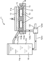
- the polishing apparatus used in the rough polishing step is not particularly limited as long as it is a polishing apparatus used for manufacturing a glass substrate. Specifically, there is a polishing apparatus 1 as shown in FIG. FIG. 7 is a schematic cross-sectional view showing an example of the polishing apparatus 1 used in the rough polishing process and the precision polishing process in the method for manufacturing a glass substrate for a magnetic information recording medium according to this embodiment.
- the polishing apparatus 11 includes an apparatus main body 11a and a polishing liquid supply unit 11b that supplies a polishing liquid to the apparatus main body 11a.
- the apparatus main body 11a includes a disk-shaped upper surface plate 12 and a disk-shaped lower surface plate 13, and they are arranged at intervals in the vertical direction so that they are parallel to each other. Then, the disk-shaped upper surface plate 12 and the disk-shaped lower surface plate 13 rotate in directions opposite to each other.
- a polishing pad 15 for polishing both the front and back surfaces of the glass substrate 10 is attached to each of the opposing surfaces of the disk-shaped upper surface plate 12 and the disk-shaped lower surface plate 13.
- the polishing pad 15 used in the rough polishing step is not particularly limited as long as it is a polishing pad used in the rough polishing step.
- a hard polishing pad made of polyurethane or the like can be used.
- a plurality of rotatable carriers 14 are provided between the disk-shaped upper surface plate 12 and the disk-shaped lower surface plate 13.
- the carrier 14 is provided with a plurality of substrate holding holes 51, and the glass substrate 10 can be fitted into the substrate holding holes 51.
- the carrier 14 may have 100 substrate holding holes 51 so that 100 glass substrates 10 can be fitted and arranged. Then, 100 glass substrates 10 can be processed by one process (1 batch).
- the carrier 14 sandwiched between the surface plates 12 and 13 via the polishing pad holds the plurality of glass substrates 10 and rotates in the same direction as the lower surface plate 13 with respect to the center of rotation of the surface plates 12 and 13 while rotating.
- the disk-shaped upper surface plate 12 and the disk-shaped lower surface plate 13 can be operated by separate driving.
- the polishing slurry 16 is supplied between the upper surface plate 12 and the glass substrate 10 and between the lower surface plate 13 and the glass substrate 10, thereby the glass substrate 10. Rough polishing can be performed.
- the polishing slurry supply unit 11b includes a liquid storage unit 110 and a liquid recovery unit 120.
- the liquid reservoir 110 includes a liquid reservoir main body 110a and a liquid supply pipe 110b having a discharge port 110e extending from the liquid reservoir main body 110a to the apparatus main body 11a.
- the liquid recovery part 120 was extended to the liquid recovery part main body 120a, the liquid recovery pipe 120b extended from the liquid recovery part main body 120a to the apparatus main body part 11a, and the polishing slurry supply part 11b from the liquid recovery part main body 120a.
- a liquid return pipe 120c is a liquid return pipe 120c.
- the polishing slurry 16 put in the liquid storage unit main body 110a is supplied from the discharge port 110e of the liquid supply pipe 110b to the apparatus main body part 11a, and from the apparatus main body part 11a via the liquid recovery pipe 120b, the liquid recovery part main body 120a.
- the recovered polishing slurry 16 is returned to the liquid storage part 110 via the liquid return pipe 120c and can be supplied again to the apparatus main body part 11a.
- the polishing slurry 16 used here is a liquid in which an abrasive is dispersed in water, that is, a slurry liquid.
- the abrasive include an abrasive containing cerium oxide.
- the average particle diameter of the cerium oxide abrasive is preferably about 0.4 to 1.6 ⁇ m.
- polishing pad 15 used here is a foam of synthetic resin such as urethane or polyester containing a cerium oxide abrasive.
- the chemical strengthening process in the manufacturing method of this invention is a well-known method, it will not specifically limit. Specifically, for example, a step of immersing a glass substrate in a chemical strengthening treatment liquid and the like can be mentioned. By doing so, a chemical strengthening layer can be formed in the surface of a glass substrate, for example, 5 micrometer area
- alkali metal ions such as lithium ions and sodium ions contained in the glass substrate are potassium ions having a larger ionic radius. It is carried out by an ion exchange method for substituting with alkali metal ions. Due to the strain caused by the difference in ion radius, compressive stress is generated in the ion-exchanged region, and the surface of the glass substrate is strengthened.
- the reinforcing layer is suitably formed by this chemical strengthening step by using the glass composition having the above glass composition as the glass substrate that is a raw material of the glass substrate.
- the glass composition having the above glass composition As the glass substrate that is a raw material of the glass substrate.
- the content of Na 2 O is large, and the sodium ions of this Na 2 O are added to the chemical strengthening treatment liquid. It is thought that it is easily exchanged for contained potassium ions.
- the polishing agent used in the polishing step before the chemical strengthening step here the rough polishing step, is an abrasive having the above composition, the amount of alkaline earth metal adhering to the surface of the glass substrate The chemical strengthening is considered to be uniform. Therefore, a glass substrate excellent in impact resistance can be produced by performing a precision polishing step on a glass substrate that has been subjected to suitable chemical strengthening as in this embodiment.
- the chemical strengthening treatment solution is not particularly limited as long as it is a chemical strengthening treatment solution used in the chemical strengthening step in the method for producing a glass substrate for a magnetic information recording medium.
- a melt containing potassium ions a melt containing potassium ions and sodium ions, and the like can be given.
- melts obtained by melting potassium nitrate, sodium nitrate, potassium carbonate, sodium carbonate, and the like examples include melts obtained by melting potassium nitrate, sodium nitrate, potassium carbonate, sodium carbonate, and the like.
- a melt obtained by melting potassium nitrate and a melt obtained by melting sodium nitrate are preferably mixed in approximately the same amount.
- the precision polishing process is a mirror polishing process that finishes a smooth mirror surface having a surface roughness (Rmax) of about 6 nm or less, for example, while maintaining the flat and smooth main surface obtained in the rough polishing process.
- the precision polishing step is performed, for example, by using a polishing apparatus similar to that used in the rough polishing step and replacing the polishing pad from a hard polishing pad to a soft polishing pad.
- the surface to be polished in the precision polishing step is the main surface, similar to the surface to be polished in the rough polishing step.
- abrasive used in the precision polishing process an abrasive that causes less scratching even if the polishing performance is lower than that used in the rough polishing process is used.
- a polishing agent containing silica-based abrasive grains having a particle diameter lower than that of the polishing agent used in the rough polishing step.
- the average particle diameter of the silica-based abrasive is preferably about 20 nm.
- polishing agent is supplied to a glass substrate, a polishing pad and a glass substrate are slid relatively, and the surface of a glass substrate is mirror-polished.
- scrub cleaning is performed as a cleaning process after the second polishing process.
- it is not limited to scrub cleaning, and any cleaning method that can clean the surface of the glass substrate after the polishing step may be used.
- Ultrasonic detergent cleaning and drying treatment are performed on the glass substrate that has been scrubbed if necessary.
- the cleaning liquid remaining on the glass substrate surface is removed using IPA or the like, and the substrate surface is dried.
- IPA isopropyl alcohol
- an IPA (isopropyl alcohol) cleaning process is performed for 3 minutes to remove water on the substrate.
- an IPA (isopropyl alcohol) vapor drying step is performed for 3 minutes, and the liquid IPA adhering to the substrate is dried while being removed by the IPA vapor.
- the substrate drying process is not limited to this, and a method generally known as a glass substrate drying method such as spin drying or air knife drying may be used.
- Glass substrates that are judged to be non-defective products in the inspection process are stored in a glass substrate storage case in a clean environment and vacuum-packed so that foreign materials do not adhere to the surface. Shipped.
- FIG. 8 is a partial cross-sectional perspective view showing a magnetic disk as an example of a magnetic recording medium using the glass substrate for magnetic information recording medium manufactured by the method for manufacturing a glass substrate for magnetic information recording medium according to the present embodiment. is there.
- the magnetic disk D includes a magnetic film 102 formed on the main surface of a circular glass substrate 101 for a magnetic information recording medium. For the formation of the magnetic film 102, a known method is used.
- a formation method for forming a magnetic film 102 by spin-coating a thermosetting resin in which magnetic particles are dispersed on a glass substrate 101 for a magnetic information recording medium, or a glass substrate for a magnetic information recording medium
- a formation method for forming the magnetic film 102 on the substrate 101 by sputtering
- a formation method electroless plating method
- electroless plating method for forming the magnetic film 102 on the glass substrate 101 for magnetic information recording medium by electroless plating
- the thickness of the magnetic film 102 is about 0.3 to 1.2 ⁇ m in the case of the spin coating method, and about 0.04 to 0.08 ⁇ m in the case of the sputtering method, and is based on the electroless plating method. In some cases, the thickness is about 0.05 to 0.1 ⁇ m. From the viewpoint of thinning and densification, film formation by sputtering is preferable, and film formation by electroless plating is preferable.
- the magnetic material used for the magnetic film 102 can be any known material and is not particularly limited.
- the magnetic material is preferably, for example, a Co-based alloy based on Co having high crystal anisotropy in order to obtain a high coercive force, and Ni or Cr added for the purpose of adjusting the residual magnetic flux density. More specifically, CoPt, CoCr, CoNi, CoNiCr, CoCrTa, CoPtCr, CoNiPt, CoNiCrPt, CoNiCrTa, CoCrPtB, CoCrPtSiO, and the like whose main component is Co can be given.
- the magnetic film 102 has a multilayer structure (for example, CoPtCr / CrMo / CoPtCr, CoCrPtTa / CrMo / CoCrPtTa, etc.) divided by a nonmagnetic film (for example, Cr, CrMo, CrV, etc.) in order to reduce noise.
- a multilayer structure for example, CoPtCr / CrMo / CoPtCr, CoCrPtTa / CrMo / CoCrPtTa, etc.
- ferrite or iron - may be a rare earth, also, Fe in a non-magnetic film made of SiO 2, BN, etc., Co, FeCo, CoNiPt and the like
- a granular material having a structure in which the magnetic particles are dispersed may be used.
- either an inner surface type or a vertical type recording format may be used for recording on the magnetic film 102.
- the surface of the magnetic film 102 may be thinly coated with a lubricant.
- a lubricant include those obtained by diluting perfluoropolyether (PFPE), which is a liquid lubricant, with a freon-based solvent.
- an underlayer or a protective layer may be provided for the magnetic film 102.
- the underlayer in the magnetic disk D is appropriately selected according to the magnetic film 102.
- the material for the underlayer include at least one material selected from nonmagnetic metals such as Cr, Mo, Ta, Ti, W, V, B, Al, and Ni.
- the material of the underlayer is preferably Cr alone or a Cr alloy from the viewpoint of improving magnetic characteristics.
- the underlayer is not limited to a single layer, and may have a multi-layer structure in which the same or different layers are stacked.
- Examples of such an underlayer having a multilayer structure include multilayer underlayers such as Cr / Cr, Cr / CrMo, Cr / CrV, NiAl / Cr, NiAl / CrMo, and NiAl / CrV.
- Examples of the protective layer that prevents wear and corrosion of the magnetic film 102 include a Cr layer, a Cr alloy layer, a carbon layer, a hydrogenated carbon layer, a zirconia layer, and a silica layer. These protective layers can be continuously formed with the underlayer and the magnetic film 102 by an in-line sputtering apparatus. These protective layers may be a single layer, or may be a multi-layer structure composed of the same or different layers.
- a SiO 2 layer may be formed on the Cr layer.
- Such a SiO 2 layer is formed by dispersing and applying colloidal silica fine particles in a tetraalkoxysilane diluted with an alcohol-based solvent on the Cr layer and further baking.
- the glass substrate 101 for magnetic information recording medium is formed with the above-described composition. It can be done with high reliability.
- the glass substrate 101 for magnetic information recording media in this embodiment was used for a magnetic recording medium
- the glass substrate for magnetic information recording media in this embodiment 101 can also be used for magneto-optical disks, optical disks, and the like.
- a general glass substrate used for manufacturing a glass substrate for information recording media is prepared, and each manufacturing process (glass melting process, forming process, heat treatment process, first lapping process, coring process, inner and outer diameters)
- the sample was transferred with the transfer rod jig of Examples 1 to 7, and the media evaluation of the subsequent glass substrate was performed.
- Example 1 As the transfer rod jig of Example 1, a transfer rod jig having a surface roughness Ra of 1.5 ⁇ m, a friction coefficient of 0.3, and a groove angle of 70 degrees was used.
- Example 2 The transfer rod jig of Example 2 was used with a surface roughness Ra of 1.5 ⁇ m, a friction coefficient of 0.3, and a groove angle of 100 degrees.
- Example 3 The transfer rod jig of Example 3 was used with a surface roughness Ra of 1.5 ⁇ m, a friction coefficient of 0.3, and a groove angle of 130 degrees.
- Example 4 As the transfer rod jig of Example 4, a transfer rod jig having a surface roughness Ra of 1.0 ⁇ m, a friction coefficient of 0.3, and a groove angle of 100 degrees was used.
- Example 5 As the transfer rod jig of Example 5, a transfer rod jig having a surface roughness Ra of 0.5 ⁇ m, a friction coefficient of 0.3, and a groove angle of 100 degrees was used.
- Example 6 The transfer rod jig of Example 6 was used with a surface roughness Ra of 1.0 ⁇ m, a friction coefficient of 0.2, and a groove angle of 100 degrees.
- Example 7 The transfer rod jig of Example 7 was used with a surface roughness Ra of 1.0 ⁇ m, a friction coefficient of 0.1, and a groove angle of 100 degrees.
- Table 1 shows the results of the media evaluation of the read / write error in the magnetic recording medium manufactured by transferring with the transfer rod jig of Examples 1 to 7.
- Example 2 in which the angle of the V-shaped groove provided on the transfer rod jig was 100 degrees, compared to Examples 1 and 3 in which the angle deviated from 90 to 120 degrees was provided. Write errors were few, and the media evaluation was high.
- Example 5 in which the surface roughness Ra of the transfer rod jig was 0.5 ⁇ m, the media evaluation was very high, and gradually became rougher as in Example 4 of 1.0 ⁇ m and Example 2 of 1.5 ⁇ m. Then the media evaluation was low. Accordingly, it has been clarified that the surface roughness Ra of the transfer rod jig is preferably 1.0 ⁇ m or less, although it is in a range where there is no problem in exhibiting even if it is larger than 1.0 ⁇ m.
- Example 7 where the friction coefficient of the transfer rod jig was 0.1, evaluation of the media was much higher than in Examples 6 and 4 where the friction coefficient was 0.2. It became very expensive. In other words, if the above evaluation is taken into account, the groove angle is 90 to 120 degrees, the surface roughness Ra of the transfer rod jig is 1.0 ⁇ m or less, and the coefficient of friction is 0.2 or less. It has been clarified that the glass substrate for magnetic information recording medium after the transfer has very few read / write errors.
- the method for manufacturing a glass substrate for magnetic information recording medium is the method for manufacturing a glass substrate for magnetic information recording medium, comprising the transfer step of transferring the glass substrate using a transfer rod jig.
- a plurality of points arranged side by side on the first line extending in the longitudinal direction of the jig and a plurality of points arranged side by side on a second line different from the first line on the peripheral surface of the jig Are formed on the circumferential surface of the jig so as to be connected one-to-one in order from one end side in the longitudinal direction of the jig, and are arranged in parallel on a first line extending in the longitudinal direction of the jig
- a transfer rod jig having a different first pitch between the plurality of points and a second pitch between the plurality of points arranged in parallel on the second line is used.
- the glass for a magnetic information recording medium having a high degree of cleaning with less contamination due to environmental re-attachment or the like.
- a method for manufacturing a substrate can be provided. Further, it is possible to provide a glass substrate for a magnetic information recording medium that does not cause head crash even when mounted on a hard disk having a very small head flying height.
- an interval at which the plurality of glass substrates are arranged in the step before the transfer step corresponds to the first pitch
- the plurality of glass substrates is arranged in the step after the transfer step. It is preferable that the intervals respectively correspond to the second pitch.
- a group consisting of a plurality of points different from the group consisting of a plurality of points arranged side by side on the second line is provided in the jig longitudinal direction, It is preferable that the distance in the jig longitudinal direction between the points closest to the other group in the group is larger than the second pitch.
- the cross-sectional shape of the groove on the peripheral surface of the transfer rod jig is a V shape of 90 to 120 degrees.
- the surface roughness Ra of the surface of the transfer rod jig is preferably 1.0 ⁇ m or less. If it is such a structure, when moving a glass substrate along V groove
- the friction coefficient of the surface of the transfer rod jig is 0.2 or less.
- the glass substrate for magnetic information recording medium according to the present invention is produced by using the method for producing a glass substrate for magnetic information recording medium.
- the transfer of the substrate between each process is easily performed in a short time, thereby preventing the occurrence of re-contamination caused by surface defects or environment due to contact between the substrates, As a result, it is possible to provide a method for manufacturing a glass substrate for a magnetic information recording medium that does not cause head crash even when mounted on a hard disk with a slight head flying height.
Landscapes
- Engineering & Computer Science (AREA)
- Manufacturing & Machinery (AREA)
- Manufacturing Of Magnetic Record Carriers (AREA)
Abstract
イオン系コンタミネーションが少なく、かつ乾燥不良が起きず、その結果ヘッド浮上量が微少なハードディスクに搭載してもヘッドクラッシュを起こさない磁気情報記録媒体用ガラス基板の製造方法を提供することを目的とする。移載棒治具を用いてガラス基板を移し替える移載工程を有する磁気情報記録媒体用ガラス基板の製造方法において、前記移載棒治具の周面上において、前記治具の長手方向に伸びる第1の線上に並設された複数の点と、前記第1の線上とは異なる第2の線上に並設された複数の点とを治具の長手方向の一端側から順に1対1に結ぶように治具の周面に形成された複数の溝が設けられ、前記治具の長手方向に伸びる第1の線上に並設された複数の点間の第1のピッチと、前記第2の線上に並設された複数の点間の第2のピッチとが異なる移載棒治具を用いることを特徴とする磁気情報記録媒体用ガラス基板の製造方法を用いる。
Description
本発明は、本発明は、磁気情報記録媒体用ガラス基板の製造方法及び磁気情報記録媒体用ガラス基板に関するものである。
磁気情報記録装置は、磁気、光及び光磁気等を利用することによって、情報を情報記録媒体に記録させるものである。その代表的なものとしては、例えば、ハードディスクドライブ装置等が挙げられる。ハードディスクドライブ装置は、基板上に記録層を形成した情報記録媒体としての磁気ディスクに対し、磁気ヘッドによって磁気的に情報を記録する装置である。このような情報記録媒体の基材、いわゆるサブストレートとしては、ガラス基板が好適に用いられている。
また、ハードディスクドライブ装置は、磁気ヘッドを磁気ディスクに接触することなく、磁気ディスクに対し僅か数nm程度浮上させ、高速回転させながら磁気ディスクに情報を記録させている。さらに、近年においては、ますますハードディスクの記録密度が向上しており、それに伴って磁気ヘッドと磁気ディスクの差(以下、ヘッド浮上量という。)が小さくなってきている。特に、DFH(Dynamic Flying Height)機構を有するようなハードディスクにおいては、ヘッド浮上量が3nm以下のものが開発されている。しかしながら、DFH機構においては、ヘッド浮上量が極めて小さいために、磁気ヘッドと磁気ディスクとが衝突してヘッドクラッシュが生じるといった問題が頻発していた。
また、近年のハードディスクドライブ装置は、その記録密度が向上していることにより、そのハードディスクに使用される基板の表面清浄性の高いものが要求されてきている。さらに、この基板の表面清浄性を高めるために、磁気情報記録媒体用ガラス基板は、微小な付着物が取り除かれたものが強く求められている。
特許文献1には、前記ヘッドクラッシュを防ぐために、磁気情報記録媒体用ガラス基板を収納容器に収納する際の雰囲気を、光触媒に対して光を照射し雰囲気中の化合物を分解する処理を施した雰囲気とし、この雰囲気とともに、磁気ディスク用ガラス基板を収納容器に収納する技術が開示されている。
しかし、上記の方法では、静電的に空気などからイオン系コンタミネーションが入り込み、ガラス基板にイオンコンタミネーションが付着してしまう。また、収納容器の内部はガラス基板を収納できるように複雑な形状になっている為に、光が一様に照射できずに、容器内にはコンタミ付着が残存してしまうという問題がある。
本発明の目的は、ガラス基板の製造工程において、各工程間の基板の移載を短時間で容易に行うことで、ハンドリングエラーによる表面欠陥や環境起因の再汚染の発生を防止し、その結果ヘッド浮上量が微小なハードディスクに搭載してもヘッドクラッシュを起こさない磁気情報記録媒体用ガラス基板の製造方法を提供することである。
すなわち、本発明にかかる磁気情報記録媒体用ガラス基板の製造方法は、移載棒治具を用いてガラス基板を移し替える移載工程を有する磁気情報記録媒体用ガラス基板の製造方法において、前記移載棒治具の周面上において、前記治具の長手方向に伸びる第1の線上に並設された複数の点と、前記第1の線上とは異なる第2の線上に並設された複数の点とを治具の長手方向の一端側から順に1対1に結ぶように治具の周面に形成された複数の溝が設けられ、前記治具の長手方向に伸びる第1の線上に並設された複数の点間の第1のピッチと、前記第2の線上に並設された複数の点間の第2のピッチとが異なる移載棒治具を用いることを特徴とする。
上記並びにその他の本発明の目的、特徴及び利点は、以下の詳細な記載と添付図面から明らかになるであろう。
磁気情報記録媒体用ガラス基板は、通常、プラスチック製の保管ケースに収納されて移送され、次工程へと流れていく。この各工程間のガラス基板の移動は最終工程に近いほど表面欠陥、再汚染の発生源となりやすい。つまり、できるだけ基板の移動回数を減らし、移動を短時間で終わらせるほうが再汚染防止に繋がる。
一方、基板出荷ケースは物流の関係上、決められた枚数(例えば1ケースに25枚)のディスクを特定のピッチ、即ちディスク間間隔で収納されることとなり、この枚数を変更することは難しい。
加工や洗浄の前工程でも同じピッチの保管ケースを使用していれば、各工程間におけるケース内基板の移載に大きな問題はないが、生産性向上の為や各工程における処理条件の関係で加工や洗浄では異なる枚数、異なるピッチの運搬・支持用治具を使用することがある。また、同じ枚数の運搬・支持用治具であっても品質向上の為にディスク間のピッチが異なる場合もある。
このため、工程間におけるケース内基板の移載が困難になり、極端な場合は1枚ずつの機械搬送にて移し替えていたため、ハンドリングエラーによる表面欠陥や環境起因の再汚染の発生が多発していた。さらにこの表面欠陥や再汚染の発生が原因となってメディア評価においてはリードライトエラーが多く発生していた。
前記課題を解決するために、本発明者らは、磁気情報記録媒体用ガラス基板の製造工程における移載、及びその収納に用いられる移載用治具に着目し、鋭意検討を行った。この結果、工程間でのガラス基板の保持ピッチが異なる場合、周面の一端上に複数の溝、及び別端上にまた複数の溝がそれぞれ連続的に刻まれており、ガラス基板の内径をこれらの溝で保持し、回転させることでピッチを変更できる移載棒治具を用いて収納、移送することで環境起因の再付着等によるコンタミネーションが少なく、洗浄度の高い磁気情報記録媒体用ガラス基板を製造し得ることを見出した。さらに、前記磁気情報記録媒体用ガラス基板であれば、ヘッド浮上量が3nm以下と微少なハードディスクに搭載してもヘッドクラッシュを起こしにくいことを見出した。
以下に、本発明の好ましい実施の形態並びに実施例について説明する。しかしながら、本発明は、以下に説明する実施形態や実施例の製造方法に限られているわけではない。
本実施形態に係る磁気情報記録媒体用ガラス基板の製造方法は、移載棒治具を用いてガラス基板を移し替える移載工程を有する磁気情報記録媒体用ガラス基板の製造方法において、前記移載棒治具の周面上において、前記治具の長手方向に伸びる第1の線上に並設された複数の点と、前記第1の線上とは異なる第2の線上に並設された複数の点とを治具の長手方向の一端側から順に1対1に結ぶように治具の周面に形成された複数の溝が設けられ、前記治具の長手方向に伸びる第1の線上に並設された複数の点間の第1のピッチと、前記第2の線上に並設された複数の点間の第2のピッチとが異なる移載棒治具を用いることを特徴とする。
また、本実施形態に係る磁気情報記録媒体用ガラス基板の製造方法は、後述するガラス基板の製造工程の各工程間の前後において前記移載棒治具を用いた移載工程を有していれば、特に限定されない。これらの各工程間の中でも特に、本発明の製造方法における移載工程は、最終洗浄工程が施されたガラス基板を出荷ケースに移載する時に最も有効的に用いることができる。
磁気情報記録媒体用ガラス基板の製造方法としては、例えば、ガラス溶融工程、形成工程、熱処理工程、第1ラッピング工程、コアリング加工工程、内・外径加工工程、第2ラッピング工程、端面研磨加工工程、第1ポリッシング工程(粗研磨工程)、化学強化工程、第2ポリッシング工程(精密研磨工程)、洗浄工程、移載工程、検査工程等を備える方法等が挙げられる。そして、前記各工程を、この順番で行うものであってもよいし、化学強化工程と第2ポリッシング工程との順番が入れ替わったものであってもよい。さらに、これら以外の工程を備える方法であってもよい。
特に、洗浄工程については、第1ポリッシング工程の後に行っても、第2ポリッシング工程の後に行ってもよく、さらに第1ポリッシング工程及び第2ポリッシング工程の後にそれぞれ一度ずつ行ってもよい。
<移載工程>
以下、本発明の製造方法における移載工程に用いられる移載棒治具について説明する。
以下、本発明の製造方法における移載工程に用いられる移載棒治具について説明する。
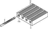
図1は本発明の移載棒治具を用いてガラス基板を移載する場合の一例を示す概要図であり、図において2は移載棒治具、10はガラス基板をそれぞれ示し、ガラス基板10は移載棒治具2によって、ガラス基板の孔に移載棒治具を挿入するようにして保持される。
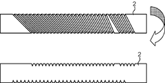
本発明の移載棒治具2は図2に示すように、その周面上に、治具の長手方向に伸びる第1の線上に並設された複数の点と、第1の線上とは異なる第2の線上に並設された複数の点とを治具の長手方向の一端側から順に1対1に結ぶように治具の周面に形成された複数の溝が設けられている。また、本発明の移載棒治具の長手方向に伸びる第1の線上に並設された複数の点間の第1のピッチと、前記第2の線上に並設された複数の点間の第2のピッチとが異なっている。このように、第1の線上に保持させたガラス基板を、移載棒を回転させることによって、第1のピッチとは異なる第2のピッチに併設する第2の線上にガラス基板を保持させることができる。
図3は、移載工程前の工程におけるケースに複数列に及んで並べられている複数のガラス基板10を、移載棒治具2を用いて移載する斜視図である。本発明の移載棒治具を用いれば、このように複数列に並べられている複数のガラス基板を、列毎に移し替えを施すことが可能である。その結果、従来のように1枚ずつ移し替えることなく、同時に1列の枚数分だけガラス基板を移し替えることができるため、移載効率が格段に向上する。
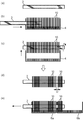
さらに図4は、本発明の移載棒治具を用いて移載する移載工程の順序を説明する正面図である。また、図4において4は移載工程前の保管ケースであり、6は移載工程後の保管ケースである。
移載する前の状態の移載棒治具2は、図4(a)に示す形状であり、この移載工程前の工程で保管されているガラス基板の間隔は、移載棒治具2の第1のピッチに対応している。したがって、ガラス基板を移載する際には、図4(b)に示すように、第1のピッチを並設している第1の線を上部にして、移載前のケース4に収納されている複数のガラス基板10の孔の中に移載棒治具2を差し込む必要がある。
図4(c)のように、移載棒治具2を各ガラス基板10の孔に挿入した後、そのまま持ち上げ、第2のピッチを並設している第2の線を上にするように回転させる。ここで、移載棒治具の周面上において、前記第2の線上に並設された複数の点からなる群とは別の複数の点からなる群が治具長手方向に設けられ、各群において相手側の群に最も近接している点同士の治具長手方向の距離Dが第2のピッチより大きいことから、図4(d)のように、前記回転後には、前記各群に分別されたガラス基板を移載棒治具上にて得ることができる。
さらに、移載工程後の工程で保管するケース6aでの複数のガラス基板の間隔は、移載棒治具2の第2のピッチに対応していることから、図4(e)に示すように、ガラス基板を保持した移載棒治具2を第2の線を上にしたまま、移載工程後の保管ケース6aに収納させることができる。なお保管ケース6aの隣に別の保管ケース6bを並設させておくと、別群に保持されたガラス基板も表面欠陥や再汚染を発生させることなく、保管ケース6bに収納させることができる。この保管ケース6bに収納された一部のガラス基板は、検査用として無駄なく使用することができる。
以上のように、前記移載工程による移載棒治具のガラス基板孔への挿入、回転、収納は、通常、本発明の製造方法における各工程の前後においてガラス基板の移し替えが行われる限り繰り返される。なお、前述のように移載工程後の収納ケースに収納を行った後には、移載棒治具をガラス基板から抜き取り、洗浄し、元の状態に戻し、同じ手順を繰り返す。このようにして、順次、複数のガラス基板への挿入、回転、収納が行われ、各製造工程の一部である移載工程として磁気情報記録媒体用ガラス基板が製造される。
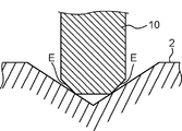
本発明の移載棒治具の周面上における溝の断面形状は、90~120度のV字形状であることが好ましい。図5は、移載棒治具2とガラス基板10を拡大した詳細図であるが、V字形状の角度が90度未満であれば、V溝面がガラス基板両主表面に接触して記録面に障害を引き起こす可能性がある。また、120度より大きければ保持が不安定となりV溝に沿ってスムーズに移動させることができない。当該溝のV字形状の角度が90~120度であれば、移載棒を回転させる際に、V溝とガラス基板両主表面への接触を防ぎ、かつ安定してスムーズにガラス基板をV溝に沿って移動させることが可能となる。
また、本発明の移載棒治具の表面の表面粗さRaは、1.0μm以下が好ましい。前記表面粗さRaが1.0μmより大きいと、V溝に沿ってガラス基板を移動させる際に、ガラス基板端面にキズが発生する恐れがあり、情報記録媒体(ドライブ)として使用した際の落下衝撃割れの起点となる場合がある。
また、本発明の前記移載棒治具の表面の摩擦係数が、0.2以下であることが好ましい。前記摩擦係数が0.2より大きいと、V溝に沿ってガラス基板をスムーズに移動させることができず、V溝とガラス基板端面の接触から発塵コンタミネーションが発生する場合がある。
本発明は、以上に説明した構成を有する移載棒治具を用いた移載工程を含む磁気情報記録媒体用ガラス基板の製造方法を提供するものであり、従来のようにガラス基板1枚1枚を機械搬送により移載を行う必要はなく、各列に並べられているガラス基板の孔に特有の溝を設けている移載棒治具を挿入し、ガラス基板を移載棒治具に保持したまま回転させ、移載後の保管ケースのピッチと同じピッチで溝が設けられている周面を上にすれば、所望の枚数群のガラス基板を分別することができるものである。したがって、このような作業を順次行えば、各工程間のガラス基板の移載時間の飛躍的な短縮を実現でき、さらにガラス基板の移動回数を減少させることができることから、ガラス基板の表面欠陥及び再汚染の防止を図ることができ、その結果、発塵コンタミネーションが少なく、その結果ヘッド浮上量が微少なハードディスクに搭載してもヘッドクラッシュを起こさないといった顕著な効果を有するものである。
以下、本発明の磁気情報記録媒体用ガラス基板の製造方法の各工程について詳述する。前述したように、どの工程間においても、本発明の移載棒治具を用いることができる。
<ガラス溶融工程>
まず、ガラス溶融工程として、ガラス素材を溶融する。ガラス基板の材料としては、例えば、SiO2、Na2O、CaOを主成分としたソーダライムガラス;SiO2、Al2O3、R2O(R=K、Na、Li)を主成分としたアルミノシリケートガラス;ボロシリケートガラス;Li2O-SiO2系ガラス;Li2O-Al2O3-SiO2系ガラス;R’O-Al2O3-SiO2系ガラス(R’=Mg、Ca、Sr、Ba)などを使用することができる。中でも、アルミノシリケートガラスやボロシリケートガラスは、耐衝撃性や耐振動性に優れるため特に好ましい。
まず、ガラス溶融工程として、ガラス素材を溶融する。ガラス基板の材料としては、例えば、SiO2、Na2O、CaOを主成分としたソーダライムガラス;SiO2、Al2O3、R2O(R=K、Na、Li)を主成分としたアルミノシリケートガラス;ボロシリケートガラス;Li2O-SiO2系ガラス;Li2O-Al2O3-SiO2系ガラス;R’O-Al2O3-SiO2系ガラス(R’=Mg、Ca、Sr、Ba)などを使用することができる。中でも、アルミノシリケートガラスやボロシリケートガラスは、耐衝撃性や耐振動性に優れるため特に好ましい。
<成型工程>
次に、成型工程として、溶融したガラスを下型に流し込み、上型によってプレス成形して円板状のガラス基板を得る。なお、円板状のガラス基板は、プレス成形によらず、例えばダウンドロー法やフロート法で形成したシートガラスを研削砥石で切り出して作製してもよい。
次に、成型工程として、溶融したガラスを下型に流し込み、上型によってプレス成形して円板状のガラス基板を得る。なお、円板状のガラス基板は、プレス成形によらず、例えばダウンドロー法やフロート法で形成したシートガラスを研削砥石で切り出して作製してもよい。
この成型工程において得たガラス基板の大きさに限定はなく、例えば、外径r1が2.5インチ(約64mm)、1.8インチ(約46mm)、1インチ(約25mm)、0.8インチ(約20mm)等で、厚みが2mm、1mm、0.63mm等の円盤状のガラス基板に加工される。また、外径r1が2.5インチ(約64mm)のときは、内径r2が0.8インチ(約20mm)等に加工される。なお、図6は、本実施形態に係る磁気情報記録媒体用ガラス基板の製造方法により製造される磁気情報記録媒体用ガラス基板を示す上面図である。
<熱処理工程>
この熱処理工程は、セッター治具に情報記録媒体用ガラス基板を挟み、熱処理炉にて加熱する工程であり、プレスガラス基板や切り出しガラス基板を耐熱部材のセッターと交互に積層し、高温電気炉工程を通過させて、基板の反りやガラス結晶化を促進させることができる。
この熱処理工程は、セッター治具に情報記録媒体用ガラス基板を挟み、熱処理炉にて加熱する工程であり、プレスガラス基板や切り出しガラス基板を耐熱部材のセッターと交互に積層し、高温電気炉工程を通過させて、基板の反りやガラス結晶化を促進させることができる。
特にガラス溶融され、プレスにより成形される工程においては、ガラスの冷却温度が均一でないため、ガラス内部に応力歪みを生じる。この応力歪みが原因となり、熱処理工程を行わずに、ラッピングやポリッシングを行うと歪みに応じて微小なクラックが生じる。このクラックの内部に研磨材や異物等が入り込み、高精度の研磨を繰り返しても凸部が発生し、不良品となる。このガラス内部の応力歪みを、円盤加工工程直後に熱処理処理することにより開放することができ、その後にラッピングやポリッシングを行ってもクラックの発生がなく不良品の発生を減少させることができる。
熱処理工程の温度は、ガラス転移温度(Tg)より20~50℃低いことが好ましい。上記範囲より低い温度だと、ガラスの内部応力の開放が不十分となり、微小クラックが発生し異物が埋まってしまう。また、上記範囲より高い温度だと、ガラスの転移温度に近くなり、表面に凹凸ムラが生じやすくなる。熱処理温度での保持時間は、20~120分が好ましい。
また、除冷スピードが早く行うと(急冷)、別の反りが発生するため、除冷スピードは遅い方が好ましい。
セッター部材の材質としては、ステンレス(オーステナイト系、マルテンサイト系)、鋳物(FC系、FCD系)、耐熱合金(Co系やNi系)、セラミックス(SiC、SiCN3)等を使用することができる。また、押圧部材表面に、硬度が高く酸化しにくいCRメッキ、Ni-P無電解メッキ等の処理を行うこともできる。押圧面の形状は、上下面とも平坦でかつ、上下面が互いに平行なものを使用することが望ましい。セッター面の形状は、温度によって変形するため、使用温度や型材料の膨張特性などを考慮し、ガラス基板主表面を加圧する際に所望の形状になるように配慮して決定される。
<第1ラッピング行程>
ラッピング工程は、前記ガラス基板を所定の板厚に加工する工程である。具体的には、ガラス基板の両面を研削(ラッピング)加工する工程等が挙げられる。このように加工することによって、ガラス基板の平行度、平坦度及び厚みを調整することができる。また、このラッピング工程は、1回であってもよいし、2回以上であってもよい。例えば、2回行う場合、1回目のラッピング工程(第1ラッピング工程)で、ガラス基板の平行度、平坦度及び厚みを予備調整し、2回目のラッピング工程(第2ラッピング工程)で、ガラス基板の平行度、平坦度及び厚みを微調整することが可能となる。
ラッピング工程は、前記ガラス基板を所定の板厚に加工する工程である。具体的には、ガラス基板の両面を研削(ラッピング)加工する工程等が挙げられる。このように加工することによって、ガラス基板の平行度、平坦度及び厚みを調整することができる。また、このラッピング工程は、1回であってもよいし、2回以上であってもよい。例えば、2回行う場合、1回目のラッピング工程(第1ラッピング工程)で、ガラス基板の平行度、平坦度及び厚みを予備調整し、2回目のラッピング工程(第2ラッピング工程)で、ガラス基板の平行度、平坦度及び厚みを微調整することが可能となる。
より具体的には、前記第1ラッピング工程としては、ガラス基板の表面全体が略均一の表面粗さとなるようにする工程等が挙げられる。その際、例えば、ガラス基板の算術平均粗さRaを複数個所測定した際に、得られたRaの最小値と最大値との差が0.01~0.4μm程度にすることが好ましい。
<コアリング加工行程>
次に、コアリング加工工程で、第1ラッピング工程後のガラス基板の中心部に穴を開ける。穴開けは、カッター部にダイヤモンド砥石等を備えたコアドリル等で研削することで得られる。
次に、コアリング加工工程で、第1ラッピング工程後のガラス基板の中心部に穴を開ける。穴開けは、カッター部にダイヤモンド砥石等を備えたコアドリル等で研削することで得られる。
<外・内径加工行程>
次に、内・外径加工工程として、ガラス基板の外周端面および内周端面を、例えば鼓状のダイヤモンド等の研削砥石により研削することで内・外径加工する。
次に、内・外径加工工程として、ガラス基板の外周端面および内周端面を、例えば鼓状のダイヤモンド等の研削砥石により研削することで内・外径加工する。
<第2ラッピング工程>
また、前記第2ラッピング工程としては、粗面化されたガラス基板の主表面を、さらに固定砥粒研磨パッドを用いて研削する行程等が挙げられる。この第2ラッピング工程においては、例えば、粗面化されたガラス基板をラッピング装置にセットし、ダイヤモンドタイル(Diamond Tile)のような表面模様付きの三次元固定研磨物を用いることで、ガラス基板の表面をラッピングすることができる。
また、前記第2ラッピング工程としては、粗面化されたガラス基板の主表面を、さらに固定砥粒研磨パッドを用いて研削する行程等が挙げられる。この第2ラッピング工程においては、例えば、粗面化されたガラス基板をラッピング装置にセットし、ダイヤモンドタイル(Diamond Tile)のような表面模様付きの三次元固定研磨物を用いることで、ガラス基板の表面をラッピングすることができる。
前記第2ラッピング行程を施すと、後述する粗研磨行程にて行われる研磨を効率良く行うことができる。また、第2ラッピング行程によって施された研磨工程に用いるガラス基板の表面粗さRaは0.10μm以下であることが好ましく、0.05μm以下であることがより好ましい。
<端面研磨加工工程>
端面研磨加工工程は、第2ラッピング工程を終えたガラス基板の外周面及び内周面の研磨加工を、端面研磨機を用いて研磨する工程である。
端面研磨加工工程は、第2ラッピング工程を終えたガラス基板の外周面及び内周面の研磨加工を、端面研磨機を用いて研磨する工程である。
<第1ポリッシング工程(粗研磨工程)>
第1ポリッシング(粗研磨工程)は、前記ラッピング工程が施されたガラス基板の表面に粗研磨を施す工程である。この粗研磨は、上述したラッピング工程で残留した傷や歪みの除去を目的とするもので、下記の研磨方法を用いて実施する。
第1ポリッシング(粗研磨工程)は、前記ラッピング工程が施されたガラス基板の表面に粗研磨を施す工程である。この粗研磨は、上述したラッピング工程で残留した傷や歪みの除去を目的とするもので、下記の研磨方法を用いて実施する。
なお、前記粗研磨工程で研磨する表面は、主表面及び/又は端面である。主表面とは、ガラス基板の面方向に平行な面である。端面とは内周端面と外周端面とからなる面のことである。また、内周端面とは、内周側の、ガラス基板の面方向に垂直な面及びガラス基板の面方向に対して傾斜を有する面である。また、外周端面とは、外周側の、ガラス基板の面方向に垂直な面及びガラス基板の面方向に対して傾斜を有する面である。
粗研磨工程で用いる研磨装置は、ガラス基板の製造に用いる研磨装置であれば、特に限定されない。具体的には、図7に示すような研磨装置1が挙げられる。なお、図7は、本実施形態に係る磁気情報記録媒体用ガラス基板の製造方法における粗研磨工程や精密研磨工程で用いる研磨装置1の一例を示す概略断面図である。
図7に示すような研磨装置11は、両面同時研削可能な装置である。また、この研磨装置11は、装置本体部11aと、装置本体部11aに研磨液を供給する研磨液供給部11bとを備えている。
装置本体部11aは、円盤状の上定盤12と円盤状の下定盤13とを備えており、それらが互いに平行になるように上下に間隔を隔てて配置されている。そして、円盤状の上定盤12と円盤状の下定盤13とが、互いに逆方向に回転する。
この円盤状の上定盤12と円盤状の下定盤13との対向するそれぞれの面にガラス基板10の表裏の両面を研磨するための研磨パッド15が貼り付けられている。この粗研磨工程で使用する研磨パッド15は、粗研磨工程で用いられる研磨パッドであれば、特に限定されない。具体的には、例えば、ポリウレタン製の硬質研磨パッド等が挙げられる。
また、円盤状の上定盤12と円盤状の下定盤13との間には、回転可能な複数のキャリア14が設けられている。このキャリア14は、複数の基板保持用孔51が設けられており、この基板保持用孔51にガラス基板10をはめ込んで配置することができる。キャリア14としては、例えば、基板保持用孔51を100個有していて、100枚のガラス基板10をはめ込んで配置できるように構成されていてもよい。そうすると、一回の処理(1バッチ)で100枚のガラス基板10を処理できる。
研磨パッドを介して定盤12、13に挟まれているキャリア14は、複数のガラス基板10を保持した状態で、自転しながら定盤12,13の回転中心に対して下定盤13と同じ方向に公転する。なお、円盤状の上定盤12と円盤状の下定盤13とは、別駆動で動作することができる。このように動作している研磨装置11において、研磨スラリー16を上定盤12とガラス基板10との間、及び下定盤13とガラス基板10との間、夫々に供給することでガラス基板10の粗研磨を行うことができる。
研磨スラリー供給部11bは、液貯留部110と液回収部120とを備えている。液貯留部110は、液貯留部本体110aと、液貯留部本体110aから装置本体部11aに延ばされた吐出口110eを有する液供給管110bとを備えている。液回収部120は、液回収部本体120aと、液回収部本体120aから装置本体部11aに延ばされた液回収管120bと、液回収部本体120aから研磨スラリー供給部11bに延ばされた液戻し管120cとを備えている。
そして、液貯留部本体110aに入れられた研磨スラリー16は、液供給管110bの吐出口110eから装置本体部11aに供給され、装置本体部11aから液回収管120bを介して液回収部本体120aに回収される。また、回収された研磨スラリー16は、液戻し管120cを介して液貯留部110に戻され、再度、装置本体部11aに供給可能とされている。
ここで用いる研磨スラリー16は、研磨剤を水に分散させた状態の液体、すなわち、スラリー液である。研磨材としては酸化セリウムを含む研磨剤等が挙げられる。この酸化セリウム砥粒の平均粒子径としては、0.4~1.6μm程度であることが好ましい。
また、ここで用いる研磨パッド15は、ウレタンやポリエステル等の合成樹脂の発泡体に、酸化セリウム研磨剤を含有させたものである。
<化学強化工程>
本発明の製造方法における化学強化工程は、公知の方法であれば、特に限定されない。具体的には、例えば、ガラス基板を化学強化処理液に浸漬させる工程等が挙げられる。そうすることによって、ガラス基板の表面、例えば、ガラス基板表面から5μmの領域に化学強化層を形成することができる。そして、化学強化層を形成することで耐衝撃性、耐振動性及び耐熱性等を向上させることができる。
本発明の製造方法における化学強化工程は、公知の方法であれば、特に限定されない。具体的には、例えば、ガラス基板を化学強化処理液に浸漬させる工程等が挙げられる。そうすることによって、ガラス基板の表面、例えば、ガラス基板表面から5μmの領域に化学強化層を形成することができる。そして、化学強化層を形成することで耐衝撃性、耐振動性及び耐熱性等を向上させることができる。
より詳しくは、化学強化工程は、加熱された化学強化処理液にガラス基板を浸漬させることによって、ガラス基板に含まれるリチウムイオンやナトリウムイオン等のアルカリ金属イオンをそれよりイオン半径の大きなカリウムイオン等のアルカリ金属イオンに置換するイオン交換法によって行われる。イオン半径の違いによって生じる歪みにより、イオン交換された領域に圧縮応力が発生し、ガラス基板の表面が強化される。
本実施形態では、ガラス基板の原料であるガラス基板として、上記のようなガラス組成のものを用いることによって、この化学強化工程により、強化層が好適に形成されると考えられる。具体的には、ガラス基板のアルカリ成分であるLi2O、Na2O、及びK2Oのうち、Na2Oの含有量が多く、このNa2Oのナトリウムイオンが、化学強化処理液に含まれるカリウムイオンに交換されやすいためと考えられる。さらに、化学強化工程を施す前の研磨工程、ここでは粗研磨工程で用いる研磨剤が、上記のような組成の研磨剤であるので、ガラス基板の表面に付着しているアルカリ土類金属の量が少なく、化学強化が均一になされると考えられる。よって、本実施形態のように、好適な化学強化がなされたガラス基板に、精密研磨工程を行うことによって、耐衝撃性に優れたガラス基板を製造することができる。
化学強化処理液としては、磁気情報記録媒体用ガラス基板の製造方法における化学強化工程で用いられる化学強化処理液であれば、特に限定されない。具体的には、例えば、カリウムイオンを含む溶融液、及びカリウムイオンやナトリウムイオンを含む溶融液等が挙げられる。
これらの溶融液としては、例えば、硝酸カリウム、硝酸ナトリウム、炭酸カリウム、及び炭酸ナトリウム等を溶融させて得られた溶融液等が挙げられる。この中でも、硝酸カリウムを溶融させて得られた溶融液と硝酸ナトリウムを溶融させて得られた溶融液とを組み合わせて用いることが、融点が低く、ガラス基板の変形を防止する観点から好ましい。その際、硝酸カリウムを溶融させて得られた溶融液と硝酸ナトリウムを溶融させて得られた溶融液とを、ほぼ同量ずつの混合させた混合液であることが好ましい。
<第2ポリッシング工程(精密研磨工程)>
精密研磨工程は、前記粗研磨工程で得られた平坦平滑な主表面を維持しつつ、例えば、主表面の表面粗さ(Rmax)が6nm程度以下である平滑な鏡面に仕上げる鏡面研磨処理である、この精密研磨工程は、例えば、上記粗研磨工程で使用したものと同様の研磨装置を用い、研磨パッドを硬質研磨パッドから軟質研磨パッドに取り替えて行われる。なお、前記精密研磨工程で研磨する表面は、前記粗研磨工程で研磨する表面と同様、主表面である。
精密研磨工程は、前記粗研磨工程で得られた平坦平滑な主表面を維持しつつ、例えば、主表面の表面粗さ(Rmax)が6nm程度以下である平滑な鏡面に仕上げる鏡面研磨処理である、この精密研磨工程は、例えば、上記粗研磨工程で使用したものと同様の研磨装置を用い、研磨パッドを硬質研磨パッドから軟質研磨パッドに取り替えて行われる。なお、前記精密研磨工程で研磨する表面は、前記粗研磨工程で研磨する表面と同様、主表面である。
また、精密研磨工程で用いる研磨剤としては、粗研磨工程で用いた研磨剤より、研磨性が低くても、傷の発生がより少なくなる研磨剤が用いられる。具体的には、例えば、粗研磨工程で用いた研磨剤より、粒子径が低いシリカ系の砥粒(コロイダルシリカ)を含む研磨剤等が挙げられる。このシリカ系の砥粒の平均粒子径としては、20nm程度であることが好ましい。そして、前記研磨剤を含む研磨スラリー液をガラス基板に供給し、研磨パッドとガラス基板とを相対的に摺動させて、ガラス基板の表面を鏡面研磨する。
<洗浄工程>
次に、第2ポリッシング工程を終えた後に洗浄工程としてスクラブ洗浄を行う。特に、スクラブ洗浄に限定するものではなく、研磨工程後のガラス基板表面を清浄にできる洗浄方法であれば良い。
次に、第2ポリッシング工程を終えた後に洗浄工程としてスクラブ洗浄を行う。特に、スクラブ洗浄に限定するものではなく、研磨工程後のガラス基板表面を清浄にできる洗浄方法であれば良い。
スクラブ洗浄がなされたガラス基板に対して、必要により超音波による洗剤洗浄および乾燥処理が行われる。乾燥処理は、ガラス基板表面に残る洗浄液をIPA等を用いて除去し、基板表面を乾燥させる。例えば、スクラブ洗浄後のガラス基板に、洗剤洗浄を2槽、水リンス洗浄工程を3槽、それぞれ3分間行ない、洗浄液の残渣を除去する。次に、IPA(イソプロピルアルコール)洗浄工程を3分間行い、基板上の水を除去する。最後に、IPA(イソプロピルアルコール)蒸気乾燥工程を3分間行い、基板に付着している液状IPAをIPA蒸気により除去しつつ乾燥させる。基板の乾燥処理としてはこれに限定されるわけではなく、スピン乾燥、エアーナイフ乾燥などガラス基板の乾燥方法として一般的に知られた方法であってももちろん構わない。
<検査工程>
検査工程では、目視によるキズ、割れや異物の付着等の検査を行う。
目視では判別できないような異物、付着は、光学表面アナライザ(KLA-TENCOL社製、OSA6100)を用いて検査を行う。
検査工程では、目視によるキズ、割れや異物の付着等の検査を行う。
目視では判別できないような異物、付着は、光学表面アナライザ(KLA-TENCOL社製、OSA6100)を用いて検査を行う。
検査工程で良品と判断されたガラス基板は、異物等が表面に付着しないように、清浄な環境の中で、ガラス基板保管ケースに収納され、真空パックされた後、情報記録媒体用ガラス基板として出荷される。
<成膜工程>
図8は、本実施形態に係る磁気情報記録媒体用ガラス基板の製造方法により製造された磁気情報記録媒体用ガラス基板を用いた磁気記録媒体の一例である磁気ディスクを示す一部断面斜視図である。この磁気ディスクDは、円形の磁気情報記録媒体用ガラス基板101の主表面に形成された磁性膜102を備えている。磁性膜102の形成には、公知の常套手段による形成方法が用いられる。例えば、磁性粒子を分散させた熱硬化性樹脂を磁気情報記録媒体用ガラス基板101上にスピンコートすることによって磁性膜102を形成する形成方法(スピンコート法)や、磁気情報記録媒体用ガラス基板101上にスパッタリングによって磁性膜102を形成する形成方法(スパッタリング法)や、磁気情報記録媒体用ガラス基板101上に無電解めっきによって磁性膜102を形成する形成方法(無電解めっき法)等が挙げられる。
図8は、本実施形態に係る磁気情報記録媒体用ガラス基板の製造方法により製造された磁気情報記録媒体用ガラス基板を用いた磁気記録媒体の一例である磁気ディスクを示す一部断面斜視図である。この磁気ディスクDは、円形の磁気情報記録媒体用ガラス基板101の主表面に形成された磁性膜102を備えている。磁性膜102の形成には、公知の常套手段による形成方法が用いられる。例えば、磁性粒子を分散させた熱硬化性樹脂を磁気情報記録媒体用ガラス基板101上にスピンコートすることによって磁性膜102を形成する形成方法(スピンコート法)や、磁気情報記録媒体用ガラス基板101上にスパッタリングによって磁性膜102を形成する形成方法(スパッタリング法)や、磁気情報記録媒体用ガラス基板101上に無電解めっきによって磁性膜102を形成する形成方法(無電解めっき法)等が挙げられる。
磁性膜102の膜厚は、スピンコート法による場合では、約0.3~1.2μm程度であり、スパッタリング法による場合では、約0.04~0.08μm程度であり、無電解めっき法による場合では、約0.05~0.1μm程度である。薄膜化および高密度化の観点から、スパッタリング法による膜形成が好ましく、また、無電解めっき法による膜形成が好ましい。
磁性膜102に用いる磁性材料は、公知の任意の材料を用いることができ、特に限定されない。磁性材料は、例えば、高い保持力を得るために結晶異方性の高いCoを基本とし、残留磁束密度を調整する目的でNiやCrを加えたCo系合金等が好ましい。より具体的には、Coを主成分とするCoPt、CoCr、CoNi、CoNiCr、CoCrTa、CoPtCr、CoNiPt、CoNiCrPt、CoNiCrTa、CoCrPtTa、CoCrPtB、CoCrPtSiO等が挙げられる。
磁性膜102は、ノイズの低減を図るために、非磁性膜(例えば、Cr、CrMo、CrV等)で分割された多層構成(例えば、CoPtCr/CrMo/CoPtCr、CoCrPtTa/CrMo/CoCrPtTa等)であってもよい。磁性膜102に用いる磁性材料は、上記磁性材料の他、フェライト系や鉄-希土類系であってもよく、また、SiO2、BN等からなる非磁性膜中にFe、Co、FeCo、CoNiPt等の磁性粒子を分散した構造のグラニュラー等であってもよい。また、磁性膜102への記録には、内面型および垂直型のいずれかの記録形式が用いられてよい。
また、磁気ヘッドの滑りをよくするために、磁性膜102の表面には、潤滑剤が薄くコーティングされてもよい。潤滑剤として、例えば液体潤滑剤であるパーフロロポリエーテル(PFPE)をフレオン系などの溶媒で希釈したものが挙げられる。
さらに必要により磁性膜102に対し下地層や保護層が設けられてもよい。磁気ディスクDにおける下地層は、磁性膜102に応じて適宜に選択される。下地層の材料として、例えば、Cr、Mo、Ta、Ti、W、V、B、Al、Ni等の非磁性金属から選ばれる少なくとも一種以上の材料が挙げられる。例えば、Coを主成分とする磁性膜102の場合には、下地層の材料は、磁気特性向上等の観点からCr単体やCr合金であることが好ましい。
また、下地層は、単層とは限らず、同一または異種の層を積層した複数層構造であってもよい。このような複数層構造の下地層は、例えば、Cr/Cr、Cr/CrMo、Cr/CrV、NiAl/Cr、NiAl/CrMo、NiAl/CrV等の多層下地層が挙げられる。磁性膜102の摩耗や腐食を防止する保護層として、例えば、Cr層、Cr合金層、カーボン層、水素化カーボン層、ジルコニア層、シリカ層等が挙げられる。これら保護層は、下地層および磁性膜102と共にインライン型スパッタ装置で連続して形成することができる。また、これら保護層は、単層としてもよく、あるいは、同一または異種の層からなる複数層構成であってもよい。
なお、上記保護層上に、あるいは、上記保護層に代えて、他の保護層が形成されてもよい。例えば、上記保護層に代えて、Cr層の上にSiO2層が形成されてもよい。このようなSiO2層は、Cr層の上にテトラアルコキシシランをアルコール系の溶媒で希釈した中に、コロイダルシリカ微粒子を分散して塗布し、さらに焼成することによって形成される。
このような本実施形態における磁気情報記録媒体用ガラス基板101を基体とした磁気記録媒体は、磁気情報記録媒体用ガラス基板101が上述した組成により形成されるので、情報の記録再生を長期に亘り高い信頼性で行うことができる。
なお、上述では、本実施形態における磁気情報記録媒体用ガラス基板101を磁気記録媒体に用いた場合について説明したが、これに限定されるものではなく、本実施形態における磁気情報記録媒体用ガラス基板101は、光磁気ディスクや光ディスク等にも用いることが可能である。
以下に実施例を挙げて本発明を具体的に説明するが、本発明はこれらに限定されるものではない。
まず、情報記録媒体用ガラス基板の製造に用いられる一般的なガラス基板を用意し、各製造工程(ガラス溶融工程、形成工程、熱処理工程、第1ラッピング工程、コアリング加工工程、内・外径加工工程、第2ラッピング工程、端面研磨加工工程、第1ポリッシング工程(粗研磨工程)、化学強化工程、第2ポリッシング工程(精密研磨工程)、洗浄工程)によって得たガラス基板を、下記の実施例1~7の移載棒治具で移し替え、その後のガラス基板についてのメディア評価を行った。
(実施例1)
実施例1の移載棒治具は、その表面粗さRaを1.5μm、摩擦係数を0.3、溝の角度を70度としたものを用いた。
実施例1の移載棒治具は、その表面粗さRaを1.5μm、摩擦係数を0.3、溝の角度を70度としたものを用いた。
(実施例2)
実施例2の移載棒治具は、その表面粗さRaを1.5μm、摩擦係数を0.3、溝の角度を100度としたものを用いた。
実施例2の移載棒治具は、その表面粗さRaを1.5μm、摩擦係数を0.3、溝の角度を100度としたものを用いた。
(実施例3)
実施例3の移載棒治具は、その表面粗さRaを1.5μm、摩擦係数を0.3、溝の角度を130度としたものを用いた。
実施例3の移載棒治具は、その表面粗さRaを1.5μm、摩擦係数を0.3、溝の角度を130度としたものを用いた。
(実施例4)
実施例4の移載棒治具は、その表面粗さRaを1.0μm、摩擦係数を0.3、溝の角度を100度としたものを用いた。
実施例4の移載棒治具は、その表面粗さRaを1.0μm、摩擦係数を0.3、溝の角度を100度としたものを用いた。
(実施例5)
実施例5の移載棒治具は、その表面粗さRaを0.5μm、摩擦係数を0.3、溝の角度を100度としたものを用いた。
実施例5の移載棒治具は、その表面粗さRaを0.5μm、摩擦係数を0.3、溝の角度を100度としたものを用いた。
(実施例6)
実施例6の移載棒治具は、その表面粗さRaを1.0μm、摩擦係数を0.2、溝の角度を100度としたものを用いた。
実施例6の移載棒治具は、その表面粗さRaを1.0μm、摩擦係数を0.2、溝の角度を100度としたものを用いた。
(実施例7)
実施例7の移載棒治具は、その表面粗さRaを1.0μm、摩擦係数を0.1、溝の角度を100度としたものを用いた。
実施例7の移載棒治具は、その表面粗さRaを1.0μm、摩擦係数を0.1、溝の角度を100度としたものを用いた。
(リードライトエラーのメディア評価)
次に、実施例1~7の移載棒治具で移し替えて製造した磁気記録媒体でのリードライトエラーのメディア評価を行った結果を表1に、記録媒体でのリードライトエラーのテスト評価(n=1000測定)を表2に示す。
次に、実施例1~7の移載棒治具で移し替えて製造した磁気記録媒体でのリードライトエラーのメディア評価を行った結果を表1に、記録媒体でのリードライトエラーのテスト評価(n=1000測定)を表2に示す。


表2の評価基準、及び表1の結果から、本発明の移載棒治具を用いて移し替えることによって、リードライトエラーの少ない磁気情報記録媒体用ガラス基板を得ることができることが明らかとなった(実施例1~7)。
これらの中でも特に、移載棒治具に設けられたV字溝の角度が100度であった実施例2では、90~120度から外れた角度を設けた実施例1,3に比べてリードライトエラーは少ないものとなり、メディア評価の高いものとなった。
また、移載棒治具の表面粗さRaを0.5μmとした実施例5ではメディア評価の非常に高いものとなり、1.0μmの実施例4、1.5μmの実施例2と徐々に粗くするとメディア評価は低いものとなった。したがって、移載棒治具の表面粗さRaは1.0μmより大きくても出品に問題のない範囲ではあるが、1.0μm以下であることが好ましいことが明らかとなった。
続いて、移載棒治具の摩擦係数を0.1とした実施例7は、摩擦係数を0.2とした実施例6、0.3とした実施例4に比べてメディアの評価は非常に高いものとなった。つまり、前述の評価を加味すれば、溝の角度が90~120度、移載棒治具の表面粗さRaを1.0μm以下であって、その摩擦係数が0.2以下であると、その移載後の磁気情報記録媒体用ガラス基板は、非常にリードライトエラーの少ないものとなることが明らかとなった。
本明細書は、上記のように様々な態様の技術を開示しているが、そのうち主な技術を以下に纏める。
本発明に係る磁気情報記録媒体用ガラス基板の製造方法は、移載棒治具を用いてガラス基板を移し替える移載工程を有する磁気情報記録媒体用ガラス基板の製造方法において、前記移載棒治具の周面上において、前記治具の長手方向に伸びる第1の線上に並設された複数の点と、前記第1の線上とは異なる第2の線上に並設された複数の点とを治具の長手方向の一端側から順に1対1に結ぶように治具の周面に形成された複数の溝が設けられ、前記治具の長手方向に伸びる第1の線上に並設された複数の点間の第1のピッチと、前記第2の線上に並設された複数の点間の第2のピッチとが異なる移載棒治具を用いることを特徴とする。
このような構成によれば、工程間の前後において複数のガラス基板の移し替えが同時に可能となることから、環境起因の再付着等によるコンタミネーションが少なく、洗浄度の高い磁気情報記録媒体用ガラス基板の製造方法を提供することができる。また、ヘッド浮上量が微少なハードディスクに搭載してもヘッドクラッシュを起こさない磁気情報記録媒体用ガラス基板を提供することができる。
また、前記移載工程前の工程において複数のガラス基板が並べられている間隔が、前記第1のピッチに対応し、かつ、前記移載工程後の工程において複数のガラス基板が並べられている間隔が、前記第2のピッチにそれぞれ対応していることが好適である。このような構成であれば、工程間でのディスクの移載を短時間で容易に実施することが可能であり、基板同士の接触による表面欠陥や環境起因の再汚染の発生を防止することができる。
また、前記移載棒治具の周面上において、前記第2の線上に並設された複数の点からなる群とは別の複数の点からなる群が治具長手方向に設けられ、各群において相手側の群に最も近接している点同士の治具長手方向の距離が、第2のピッチより大きいことが好適である。このような構成であれば、移載工程前後における収納枚数が異なる場合においても、工程間でのディスクの移載を短時間で容易に実施することが可能であり、基板同士の接触による表面欠陥や環境起因の再汚染の発生を防止することができる。
また、前記移載棒治具の周面上における溝の断面形状は、90~120度のV字形状であることが好適である。このような構成であれば、移載棒を回転させる際に、V溝とガラス基板両主表面への接触を防ぎ、かつ安定してスムーズにガラス基板をV溝に沿って移動させることが可能となる。
また、前記移載棒治具の表面の表面粗さRaは、1.0μm以下であることが好適である。このような構成であれば、V溝に沿ってガラス基板を移動させる際に、ガラス基板端面へのキズ発生を防止することができる。
また、前記移載棒治具の表面の摩擦係数が、0.2以下であることが好適である。このような構成であれば、V溝に沿ってガラス基板をスムーズに移動させることができ、V溝とガラス基板端面の接触から発生する発塵コンタミネーションを防止することができる。
また、本発明に係る磁気情報記録媒体用ガラス基板は、前記磁気情報記録媒体用ガラス基板の製造方法を用いて作製されたものである。
この出願は、2011年3月30日に出願された日本国特許出願特願2011-076214を基礎とするものであり、その内容は、本願に含まれるものである。
本発明を表現するために、上述において図面を参照しながら実施形態を通して本発明を適切且つ十分に説明したが、当業者であれば上述の実施形態を変更および/または改良することは容易に為し得ることであると認識すべきである。したがって、当業者が実施する変更形態または改良形態が、請求の範囲に記載された請求項の権利範囲を離脱するレベルのものでない限り、当該変更形態または当該改良形態は、当該請求項の権利範囲に包括されると解釈される。
本発明によれば、ガラス基板の製造工程において、各工程間の基板の移載を短時間で容易に行うことで、基板同士の接触による表面欠陥や環境起因の再汚染の発生を防止し、その結果、ヘッド浮上量が微少なハードディスクに搭載してもヘッドクラッシュを起こさない磁気情報記録媒体用ガラス基板の製造方法を提供することができる。
Claims (7)
- 移載棒治具を用いてガラス基板を移し替える移載工程を有する磁気情報記録媒体用ガラス基板の製造方法において、
前記移載棒治具の周面上において、前記治具の長手方向に伸びる第1の線上に並設された複数の点と、前記第1の線上とは異なる第2の線上に並設された複数の点とを治具の長手方向の一端側から順に1対1に結ぶように治具の周面に形成された複数の溝が設けられ、
前記治具の長手方向に伸びる第1の線上に並設された複数の点間の第1のピッチと、前記第2の線上に並設された複数の点間の第2のピッチとが異なる移載棒治具を用いることを特徴とする磁気情報記録媒体用ガラス基板の製造方法。 - 前記移載工程前の工程において複数のガラス基板が並べられている間隔が、前記第1のピッチに対応し、かつ、前記移載工程後の工程において複数のガラス基板が並べられている間隔が、前記第2のピッチにそれぞれ対応していることを特徴とする請求項1に記載の磁気情報記録媒体用ガラス基板の製造方法。
- 前記移載棒治具の周面上において、前記第2の線上に並設された複数の点からなる群とは別の複数の点からなる群が治具長手方向に設けられ、
各群において相手側の群に最も近接している点同士の治具長手方向の距離が、第2のピッチより大きいことを特徴とする請求項1又は2に記載の磁気情報記録媒体用ガラス基板の製造方法。 - 前記移載棒治具の周面上における溝の断面形状は、90~120度のV字形状であることを特徴とする請求項1~3のいずれか1項に記載の磁気情報記録媒体用ガラス基板の製造方法。
- 前記移載棒治具の表面の表面粗さRaは、1.0μm以下であることを特徴とする請求項1~4のいずれか1項に記載の磁気情報記録媒体用ガラス基板の製造方法。
- 前記移載棒治具の表面の摩擦係数が、0.2以下であることを特徴とする請求項1~5のいずれか1項に記載の磁気情報記録媒体用ガラス基板の製造方法。
- 請求項1~6のいずれか1項に記載の磁気情報記録媒体用ガラス基板の製造方法を用いて作製した磁気情報記録媒体用ガラス基板。
Priority Applications (1)
| Application Number | Priority Date | Filing Date | Title |
|---|---|---|---|
| JP2012506018A JP4993047B1 (ja) | 2011-03-30 | 2011-10-14 | 磁気情報記録媒体用ガラス基板の製造方法 |
Applications Claiming Priority (2)
| Application Number | Priority Date | Filing Date | Title |
|---|---|---|---|
| JP2011-076214 | 2011-03-30 | ||
| JP2011076214 | 2011-03-30 |
Publications (1)
| Publication Number | Publication Date |
|---|---|
| WO2012131814A1 true WO2012131814A1 (ja) | 2012-10-04 |
Family
ID=46929657
Family Applications (1)
| Application Number | Title | Priority Date | Filing Date |
|---|---|---|---|
| PCT/JP2011/005776 Ceased WO2012131814A1 (ja) | 2011-03-30 | 2011-10-14 | 磁気情報記録媒体用ガラス基板の製造方法及び磁気情報記録媒体用ガラス基板 |
Country Status (1)
| Country | Link |
|---|---|
| WO (1) | WO2012131814A1 (ja) |
Citations (6)
| Publication number | Priority date | Publication date | Assignee | Title |
|---|---|---|---|---|
| JPH11306544A (ja) * | 1998-04-24 | 1999-11-05 | Fuji Electric Co Ltd | 磁気記録媒体用シッピングカセットおよびそのディスク保持具 |
| JP2008146804A (ja) * | 2006-11-15 | 2008-06-26 | Ricoh Co Ltd | ディスク基板搬送機構ならびに記録媒体ディスク |
| WO2008078528A1 (ja) * | 2006-12-26 | 2008-07-03 | Konica Minolta Opto, Inc. | 保持治具、該保持治具を用いた記録媒体用ガラス基板の製造方法、記録媒体用ガラス基板及び記録媒体 |
| JP2008243313A (ja) * | 2007-03-28 | 2008-10-09 | Hoya Corp | 磁気ディスク用ガラス基板の収納方法、磁気ディスク用ガラス基板の製造方法、磁気ディスク用ガラス基板収納体、磁気ディスク用ガラス基板の配送方法、及び、磁気ディスクの製造方法 |
| JP2010067297A (ja) * | 2008-09-09 | 2010-03-25 | Showa Denko Kk | 表面処理方法および表面処理装置 |
| JP2010113783A (ja) * | 2008-11-10 | 2010-05-20 | Konica Minolta Opto Inc | 保持治具、該保持治具を用いた記録媒体用ガラス基板の製造方法及び記録媒体の製造方法 |
-
2011
- 2011-10-14 WO PCT/JP2011/005776 patent/WO2012131814A1/ja not_active Ceased
Patent Citations (6)
| Publication number | Priority date | Publication date | Assignee | Title |
|---|---|---|---|---|
| JPH11306544A (ja) * | 1998-04-24 | 1999-11-05 | Fuji Electric Co Ltd | 磁気記録媒体用シッピングカセットおよびそのディスク保持具 |
| JP2008146804A (ja) * | 2006-11-15 | 2008-06-26 | Ricoh Co Ltd | ディスク基板搬送機構ならびに記録媒体ディスク |
| WO2008078528A1 (ja) * | 2006-12-26 | 2008-07-03 | Konica Minolta Opto, Inc. | 保持治具、該保持治具を用いた記録媒体用ガラス基板の製造方法、記録媒体用ガラス基板及び記録媒体 |
| JP2008243313A (ja) * | 2007-03-28 | 2008-10-09 | Hoya Corp | 磁気ディスク用ガラス基板の収納方法、磁気ディスク用ガラス基板の製造方法、磁気ディスク用ガラス基板収納体、磁気ディスク用ガラス基板の配送方法、及び、磁気ディスクの製造方法 |
| JP2010067297A (ja) * | 2008-09-09 | 2010-03-25 | Showa Denko Kk | 表面処理方法および表面処理装置 |
| JP2010113783A (ja) * | 2008-11-10 | 2010-05-20 | Konica Minolta Opto Inc | 保持治具、該保持治具を用いた記録媒体用ガラス基板の製造方法及び記録媒体の製造方法 |
Similar Documents
| Publication | Publication Date | Title |
|---|---|---|
| JP5335789B2 (ja) | 磁気ディスク用基板及び磁気ディスク | |
| JP5321594B2 (ja) | ガラス基板の製造方法、および磁気記録媒体の製造方法 | |
| JP5635078B2 (ja) | 磁気ディスク用ガラス基板の製造方法 | |
| JP2009193608A (ja) | 情報記録媒体用ガラス基板の製造方法、情報記録媒体用ガラス基板及び磁気記録媒体 | |
| JP2008287779A (ja) | 情報記録媒体用ガラス基板の製造方法、情報記録媒体用ガラス基板及び磁気記録媒体 | |
| JP2009173295A (ja) | 記録媒体用ガラス基板の収納容器、記録媒体用ガラス基板収納体、記録媒体用ガラス基板の製造方法、記録媒体用ガラス基板及び記録媒体 | |
| JP2009076167A (ja) | 情報記録媒体用ガラス基板の製造方法、情報記録媒体用ガラス基板及び磁気記録媒体 | |
| US20100081013A1 (en) | Magnetic disk substrate and magnetic disk | |
| JPWO2010041537A1 (ja) | ガラス基板の製造方法、および磁気記録媒体の製造方法 | |
| WO2010041536A1 (ja) | ガラス基板の製造方法、および磁気記録媒体の製造方法 | |
| JP5536481B2 (ja) | 情報記録媒体用ガラス基板の製造方法及び情報記録媒体の製造方法 | |
| JP5781845B2 (ja) | Hdd用ガラス基板、hdd用ガラス基板の製造方法、及びhdd用磁気記録媒体 | |
| JP4993047B1 (ja) | 磁気情報記録媒体用ガラス基板の製造方法 | |
| JP2012203937A (ja) | 磁気情報記録媒体用ガラス基板の製造方法 | |
| WO2014049947A1 (ja) | 情報記録媒体用ガラス基板の検査方法、及び情報記録媒体用ガラス基板の製造方法 | |
| WO2012131814A1 (ja) | 磁気情報記録媒体用ガラス基板の製造方法及び磁気情報記録媒体用ガラス基板 | |
| JP5859757B2 (ja) | Hdd用ガラス基板の製造方法 | |
| JP5071603B2 (ja) | 磁気情報記録媒体用ガラス基板の製造方法 | |
| JP2012203960A (ja) | 磁気情報記録媒体用ガラス基板の製造方法 | |
| JP5111818B2 (ja) | 磁気ディスク用ガラス基板の製造方法及び磁気ディスクの製造方法 | |
| CN103946920B (zh) | Hdd用玻璃基板的制造方法、hdd用玻璃基板以及hdd用磁记录介质 | |
| JP5360331B2 (ja) | Hdd用ガラス基板の製造方法 | |
| JP6034583B2 (ja) | 情報記録媒体用ガラス基板の製造方法、及び情報記録媒体用ガラス基板 | |
| WO2014103283A1 (ja) | 情報記録媒体用ガラス基板の製造方法 | |
| JP2012203959A (ja) | 磁気情報記録媒体用ガラス基板の製造方法 |
Legal Events
| Date | Code | Title | Description |
|---|---|---|---|
| ENP | Entry into the national phase |
Ref document number: 2012506018 Country of ref document: JP Kind code of ref document: A |
|
| 121 | Ep: the epo has been informed by wipo that ep was designated in this application |
Ref document number: 11862664 Country of ref document: EP Kind code of ref document: A1 |
|
| NENP | Non-entry into the national phase |
Ref country code: DE |
|
| 122 | Ep: pct application non-entry in european phase |
Ref document number: 11862664 Country of ref document: EP Kind code of ref document: A1 |