WO2012128227A1 - 反射鏡 - Google Patents
反射鏡 Download PDFInfo
- Publication number
- WO2012128227A1 WO2012128227A1 PCT/JP2012/056926 JP2012056926W WO2012128227A1 WO 2012128227 A1 WO2012128227 A1 WO 2012128227A1 JP 2012056926 W JP2012056926 W JP 2012056926W WO 2012128227 A1 WO2012128227 A1 WO 2012128227A1
- Authority
- WO
- WIPO (PCT)
- Prior art keywords
- glass
- glass substrate
- sealing
- layer
- reflecting mirror
- Prior art date
- Legal status (The legal status is an assumption and is not a legal conclusion. Google has not performed a legal analysis and makes no representation as to the accuracy of the status listed.)
- Ceased
Links
Images



Classifications
-
- G—PHYSICS
- G02—OPTICS
- G02B—OPTICAL ELEMENTS, SYSTEMS OR APPARATUS
- G02B5/00—Optical elements other than lenses
- G02B5/08—Mirrors
- G02B5/0808—Mirrors having a single reflecting layer
Definitions
- the present invention relates to a reflecting mirror.
- a solar thermal power generation system that condenses sunlight, generates high-temperature and high-pressure steam by the thermal energy, and drives a turbine using the steam has been studied.
- a solar heat collector a solar light collecting system, and the like, a reflecting mirror is generally used to increase the light collecting efficiency of sunlight.
- the reflecting mirror is manufactured by coating a metal thin film such as aluminum or silver as a reflective film on a transparent substrate such as a glass substrate.
- Mirrors coated with a metal thin film on a transparent substrate have a problem that the metal thin film on the surface is likely to deteriorate due to moisture, oxygen, etc. in the environmental atmosphere.
- a reflecting mirror in which a protective film made of an acrylic resin, an epoxy resin or the like is formed on the metal thin film is known.
- a protective film made of resin has insufficient water resistance, it is difficult to prevent deterioration of the metal thin film over a long period of time when installed outdoors.
- Patent Document 1 describes a reflecting mirror coated with an elastic sealant made of silicone sealant or the like along the entire periphery of a laminated glass mirror.
- Patent Document 2 a silver mirror film, a metal protective film made of copper or the like and a backing coating film are sequentially laminated on a glass substrate, and a coating made of an acrylic silicone resin is formed on the edge of these laminated films. A mirror is described.
- water barrier properties such as silicone sealants and acrylic silicone resins are not perfect, and it is difficult to maintain water resistance over a long period of time.
- the metal protective film is very thin, cracks are likely to occur gradually due to thermal expansion or the like, and there is a problem that reliability is poor.
- palladium is activated by an activation treatment with a solution containing a palladium compound on the glass substrate in order to suppress deterioration or peeling of the silver film due to intrusion of moisture.
- (Pd) is deposited as a base of a silver film, thereby improving the adhesion between the glass substrate and the silver film.
- palladium as a base layer is very expensive, it causes an increase in the manufacturing cost of the reflecting mirror.
- the reflectance of the silver film itself is lowered, which is a factor that degrades the performance of the reflecting mirror.
- An object of the present invention is to provide a reflecting mirror that is excellent in water resistance and that can reduce the manufacturing cost while improving the reflectance.
- the reflecting mirror of the present invention includes a first glass substrate having a first surface, a reflective film formed on the first surface of the first glass substrate, and a second facing the first surface.
- the first glass substrate and the second glass so as to hermetically seal the second glass substrate having a surface with a predetermined gap from the first glass substrate and the reflective film.
- a sealing glass layer formed in a peripheral portion of the substrate and between the first glass substrate and the second glass substrate; and on the first surface of the first glass substrate.
- the Pd concentration is 0.15 atomic% or less (atomic % percent) or less.
- the sealing glass layer having excellent water resistance is hermetically sealed between the first glass substrate and the second glass substrate, deterioration of the reflecting film due to moisture and the like over a long period of time. Can be suppressed. Therefore, even when the Pd concentration as the base of the reflective film is reduced, the reflective film can be prevented from being deteriorated or peeled off. ADVANTAGE OF THE INVENTION According to this invention, the reflective mirror which can maintain the outstanding reflectance over a long period of time can be provided at low cost.
- FIG. 1 is a cross-sectional view showing the configuration of the reflecting mirror according to the first embodiment
- FIG. 2 is a cross-sectional view showing the configuration of the reflecting mirror according to the second embodiment.
- the reflecting mirror 1 shown in these drawings includes a first glass substrate 2 having a first surface 2a and a second glass substrate 3 having a second surface 3a.
- the first glass substrate 2 and the second glass substrate 3 are laminated and arranged with a predetermined gap so that the first surface 2a and the second surface 3a face each other.
- the reflecting mirror 1 has a reflecting film 4 formed on the surface 2 a of the first glass substrate 2.
- the reflective film 4 is made of a metal such as silver, a silver alloy (Ag—Pt alloy, Ag—Pd alloy, etc.), aluminum or the like.
- a metal reflective film (metal reflective film) 4 can be formed by various thin film forming methods such as vapor deposition, sputtering, CVD, ion plating, ion beam irradiation, and spray coating.
- the reflective film 4 may be formed not only on the surface 2 a of the first glass substrate 2 but also on the surface 3 a of the second glass substrate 3.
- the reflecting mirror 1 according to the second embodiment includes a first reflecting film 4A formed on the surface 2a of the first glass substrate 2 and a second reflecting film formed on the surface 3a of the second glass substrate 3. 4B.
- both surfaces of the first glass substrate 2 and the second glass substrate 3 can be used as reflection surfaces.
- the reflecting mirror 1 is inverted and the second glass substrate 3 is used as the reflecting surface. By doing so, it is possible to further extend the life of the reflecting mirror 1.
- the sealing glass layer 5 is formed so as to hermetically seal the reflective film 4 including 4A and 4B. That is, the reflecting mirror 4 is positioned in an airtight space 6 of a glass package constituted by the first glass substrate 2, the second glass substrate 3, and the sealing glass layer 5.
- the sealing glass layer 5 contains a low melting point glass as an essential component, and may contain an inorganic filler such as a thermal expansion adjusting material or an electromagnetic wave absorbing material as an optional component as will be described in detail later.
- the sealing glass layer 5 is made of a melt-solidified material of a sealing glass material including a low melting point glass as an essential component and an inorganic filler as an optional component.
- the sealing glass layer 5 is substantially composed only of an inorganic material, the sealing glass layer 5 is superior in airtightness compared to a sealing material made of a conventional organic material, and has long intrusion of moisture or the like that causes deterioration of the reflective film 4. Can be prevented over time. This means that the sealing glass layer 5 can suppress deterioration and peeling of the reflective film 4. Therefore, unlike the prior art, the first glass substrate 2 and the second glass of the reflective film 4 are not deposited on the reflective film 4 without depositing palladium (Pd) as the base of the reflective film 4 in order to improve the durability of the reflective film 4. It becomes possible to maintain the adhesion to the substrate 3 over a long period of time.
- the amount can be made extremely small. That is, it is sufficient to deposit palladium in an amount that can form the reflective film 4 without unevenness without considering improvement in the adhesion of the reflective film 4 and the like.
- the palladium (Pd) concentration on the surface 2a of the first glass substrate 2 which is the formation surface of the reflecting film 4 (or 4A) and also reflected on the second glass substrate 3 are reflected.
- the palladium (Pd) concentration on the surface 3a of the second glass substrate 2 is set to 0.15 atomic% or less.
- the palladium (Pd) concentration of 0.15 atomic% or less includes the case where the palladium (Pd) concentration is 0.00 atomic%.
- the manufacturing cost of the reflective film 1 can be reduced by setting the Pd concentration of the glass substrate 2 or the surface 2a of the glass substrates 2 and 3 or the Pd concentration of the surfaces 2a and 3a to 0.15 atomic% or less. Furthermore, it is possible to suppress a decrease in the reflectance of the reflective film 4 due to palladium. Therefore, it is possible to provide a reflecting mirror 1 that can maintain an excellent reflectance over a long period of time, and to reduce the manufacturing cost of such a reflecting mirror 1.
- the Pd concentration on the surface of the glass substrate described above is a value obtained as follows. That is, the Pd concentration on the surface of the glass substrate is measured by depth direction analysis from the surface using X-ray photoelectron spectroscopy (XPS) combined with sputter etching using an Ar ion beam. More specifically, a depth direction analysis of elements of Pd, Ag, Sn, Si, Na, and O is performed, and a concentration graph in the depth direction as shown in FIG. 3 is created. Next, as shown in an enlarged view in FIG. 4, the concentration at the point where the XPS peak intensity of Pd3d is maximum (point A in FIG. 4) is defined as the Pd concentration (number of atoms%).
- XPS X-ray photoelectron spectroscopy
- each element is measured within the following energy range.
- Pd3d is 330 to 348 eV
- Ag3d is 364 to 380 eV
- Sn3d5 / 2 is 480 to 500 eV
- Si2p is 95 to 110 eV
- Na1s is 1066 to 1082 eV
- O1s is 525 to 540 eV.
- the quantification was performed by ULVAC-PHI PHI MultiPak Data Analysis Software TM Ver. This was performed using 8.2 (trade name). For quantification, a spectrum obtained by subtracting the background using the Shirley method and repeating 5-point Savitzky-Golay smoothing three times was used.
- the sputter etching time by the Ar ion beam corresponds to the depth from the surface, that is, the film thickness.
- the conversion from the sputter etching time to the film thickness was obtained from a calibration curve prepared using a standard sample having a known film thickness and the same composition. That is, it calculated as 0.5 nm / min in terms of SiO 2 .
- the XPS spectrometer used was model 5500 manufactured by Phi, and X-ray AlK ⁇ rays monochromatized with a monochromator were used as the X-ray source. Further, the detection angle of X-ray photoelectrons was 45 °, and measurement was performed by irradiating an electron shower to correct charging.
- the measurement conditions were a path energy of 117.4 eV, a step energy of 0.5 eV, and an energy resolution of 1.70 eV with a half width of Ag3d5 / 2.
- Ar sputtering was performed on an area of 3 ⁇ 3 mm 2 at an acceleration energy of 1 kV.
- a protective film made of a metal film or a resin film for improving durability may not be formed on the surface of the reflective film 4. That is, the reflective film 4 is exposed in a space 6 hermetically sealed with the first glass substrate 2, the second glass substrate 3, and the sealing glass layer 5. Even if a protective film or the like is not formed on the surface of the reflective film 4, the glass package constituted by the first glass substrate 2, the second glass substrate 3, and the sealing glass layer 5 has excellent hermetic sealing properties. ing. Therefore, even when the Pd concentration is reduced as the base of the reflective film, the deterioration or peeling of the reflective film 4 can be suppressed. Furthermore, the manufacturing cost of the reflecting mirror 1 can also be reduced by omitting the formation of the protective film on the reflecting film 4.
- a resin or the like may be filled in the hermetic space 6 formed by the glass package.
- the exposure of the reflective film 4 to the airtight space 6 means that no other film or member exists on the reflective film 4 except for the filler.
- the first and second glass substrates 2 and 3 are made of soda lime glass, alkali-free glass, chemically tempered glass, physically tempered glass, or the like having various known compositions.
- Soda lime glass has a thermal expansion coefficient of about 80 to 90 ( ⁇ 10 ⁇ 7 / ° C.).
- the alkali-free glass has a thermal expansion coefficient of about 35 to 40 ( ⁇ 10 ⁇ 7 / ° C.).
- the soda lime glass is preferably white plate glass (high transmission glass) having high transparency.
- the white plate glass (high transmission glass) referred to here is a glass having a visible light transmittance higher than that of ordinary soda lime glass and having a visible light transmittance of 90% or more. It is a glass having an iron content of 0.06% or less as Fe 2 O 3 .
- Tempered glass obtained by chemically strengthening or physically strengthening soda lime glass is preferable for enhancing the strength and reliability of the reflecting mirror 1.
- the tempered glass may be obtained by chemically strengthening or physically strengthening glass other than soda lime glass.
- “to” indicating the numerical range described above is used to mean that the numerical values described before and after it are used as a lower limit value and an upper limit value, and hereinafter “to” Used with meaning.
- the thickness of the first and second glass substrates 2 and 3 is preferably in the range of 0.03 to 5 mm. If the thickness of the glass substrates 2 and 3 is less than 0.03 mm, the strength and reliability of the reflecting mirror 1 may be insufficient. On the other hand, when the thickness of the glass substrates 2 and 3 exceeds 5 mm, not only the reflecting mirror 1 becomes heavy, but also the reflectance may decrease due to absorption of the glass substrate itself. Considering the reflectance and weight of the reflecting mirror 1, it is desirable that the thickness of the glass substrates 2 and 3 is thin, specifically 0.03 to 2.8 mm is more preferable, and more preferably 0.03 to 1 is preferable. .1 mm. Considering the strength of the reflecting mirror 1, it is desirable that the glass substrates 2 and 3 are thicker, specifically 0.07 to 5 mm, more preferably 1.1 to 5 mm.
- the thicknesses of the first and second glass substrates 2 and 3 are appropriately adjusted depending on the location where the reflective film 4 is formed. That is, when the reflective film 4 is formed only on the surface 2 a of the first glass substrate 2, the thickness of the first glass substrate 2 is preferably 0.03 to 0.7 mm, and the thickness of the second glass substrate 3. Is preferably 0.7 to 5 mm. Thereby, the strength can be improved while increasing the reflectance of the reflecting mirror 1. When the reflective film 4 is formed on both the surface 2a of the first glass substrate 2 and the surface 3a of the second glass substrate 3, the first and second layers are considered in consideration of the reflectance and strength of the reflecting mirror 1. The thickness of the glass substrates 2 and 3 is preferably 0.55 to 2.8 mm.
- the shape of the glass substrates 2 and 3 is not limited to this, and may have a curved shape.
- a reflecting mirror using a glass substrate having a curved shape is suitable for a method of collecting sunlight with a curved mirror such as a trough solar power generation.
- a reflector using a glass substrate having a curved shape is effective in collecting sunlight.
- the internal space (namely, airtight space) 6 of the glass package composed of the first glass substrate 2, the second glass substrate 3, and the sealing glass layer 5 may be filled with air.
- the airtight space 6 is vacuum (for example, the pressure is preferably 100 Pa or less) or filled with an inert gas such as nitrogen gas or argon gas.
- the airtight space 6 may be filled with resin.
- the gap between the first glass substrate 2 and the second glass substrate 3 is used to reduce the influence of the reaction between the oxygen in the filler filled in the airtight space 6 and the reflective film 4, the thermal expansion, and the like.
- the thickness of the reflective film 4 is narrow as long as the reflective film 4 and the arrangement thereof are not adversely affected.
- the distance between the first glass substrate 2 and the second glass substrate 3 is preferably 500 ⁇ m or less, more preferably 100 ⁇ m or less, and particularly preferably 10 ⁇ m or less. Spacers may be arranged in the airtight space 6 having such an interval (that is, thickness) in order to improve the strength.
- the spacer is preferably a ceramic spacer such as alumina or silica having heat resistance when the entire reflecting mirror 1 is heated in a firing furnace in the sealing step.
- a spacer made of resin or plastic may be used.
- the reaction layer 7 with the glass layer 5 is preferably formed.
- the reaction layer 7 is generated from the respective surface layers of the first and second glass substrates 2 and 3 toward the inside thereof in a region in contact with the sealing glass layers of the first and second glass substrates 2 and 3.
- the reaction layer 7 has a maximum depth of 30 nm or more from the surfaces of the first and second glass substrates in the interface region in contact with the sealing glass layer 5 of the glass substrates 2 and 3. It is desirable to generate as follows.
- the reaction layer 7 is a mixed layer of the constituent elements of the first and second glass substrates 2 and 3 and the constituent element of the sealing glass layer 5.
- the reaction layer 7 By generating such a reaction layer 7 on the surface layers of the first and second glass substrates 2 and 3 and setting the maximum depth to 30 nm or more, the first and second glass substrates 2 and 3 and The adhesive state with the sealing glass layer 5 can be strengthened. Moreover, it can also be set as a favorable airtight structure between the glass substrates 2 and 3 sealed by the sealing glass layer 5. If the maximum depth of the reaction layer 7 is less than 30 nm, there is a possibility that the effect of increasing the adhesive strength and airtightness cannot be obtained sufficiently.
- the maximum depth of the reaction layer 7 50 nm or more is more preferable, More preferably, it is 150 nm or more.
- the upper limit value of the maximum depth of the reaction layer 7 is not particularly limited, but is preferably 3000 nm or less, more preferably 2000 nm or less, and further preferably 500 nm or less.
- the reaction layer 7 has a shape in which the vicinity of the center portion protrudes in a convex shape toward the inside of the first and second glass substrates 2 and 3 from the vicinity of both end portions of the sealing glass layer 5 in the cross section in the width direction. It is preferable to have. In other words, the reaction layer 7 preferably has a concave shape in which the depth to the inside of the first and second glass substrates 2 and 3 is deeper in the vicinity of the center than the both ends of the sealing glass layer 5. . According to the reaction layer 7 having such a shape, the stress generated at the interface between the first and second glass substrates 2 and 3 and the reaction layer 7 is dispersed throughout the reaction layer 7. The adhesive strength between the glass substrates 2 and 3 and the sealing glass layer 5 can be further increased.
- the shape of the reaction layer 7 is not limited to a shape having a substantially arc-shaped cross section as shown in FIG. 5, and may be a shape having a plurality of protruding portions.
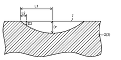
- the maximum depth D1 of the reaction layer 7 is 1.1 times or more than the depth D2 near the end of the sealing glass layer 5. (Ie, D1 / D2 ⁇ 1.1) is preferable (that is, a shape protruding toward the glass substrate and downward in FIG. 6).
- the depth D2 near the end of the reaction layer 7 is a distance of 1/10 of the distance L1 from the end when the distance from the end of the reaction layer 7 to the position having the maximum depth D1 is L1.
- the position of the maximum depth D1 and the distance L2 that is 1/10 of the distance L1 from the nearest end of the position to the position having the maximum depth D1. It is assumed that D1 / D2 is obtained based on the depth D2.
- L1 indicates the length of the reaction layer 7 in the width direction, that is, the length in the A direction in FIG. If the value of D1 / D2 exceeds 500, stress concentration is likely to occur as in the case where the depth of the reaction layer is uniform. Therefore, the value of D1 / D2 is preferably 500 or less.
- the first and second glass substrates 2, 3 and The adhesive strength with the sealing glass layer 5 can be further increased, and the stress dispersion effect at the interface between the first and second glass substrates 2 and 3 and the reaction layer 7 can be obtained with good reproducibility.
- the ratio of D1 / D2 is more preferably 2.0 or more.
- the cross-sectional area of the width direction is 50 micrometers 2 or more.
- the cross-sectional area of the reaction layer 7 is more preferably 100 ⁇ m 2 or more.
- the cross-sectional area of the reaction layer 7 can be increased by, for example, the shape of the reaction layer 7 (for example, increasing the depth).
- the cross-sectional area of the reaction layer 7 can be increased even if the width (line width) of the sealing glass layer 5 is increased, and this is also the first and second glass substrates 2 and 3 and the sealing glass layer 5. As a means for increasing the adhesive strength.
- the generation of the reaction layer can be confirmed by FE-EPMA line composition analysis in the vicinity of the adhesive interface between the first and second glass substrates 2 and 3 and the sealing glass layer 5.
- the method to show is mentioned.
- the shape of the reaction layer 7 (depth, cross-sectional area, D1 / D2 ratio, etc.), values measured by the following method are shown.
- the sealing glass layer 5 is removed by immersing the sample from which one glass substrate is removed in an etching solution.
- an acid solution that does not dissolve the glass of the glass substrate but can dissolve the constituent elements of the sealing glass layer 5 is used.
- a 30% nitric acid aqueous solution is used. Since the reaction layer 7 is a mixed layer of the constituent elements of the first and second glass substrates 2 and 3 and the constituent element of the sealing glass layer 5, the reaction layer 7 is also removed simultaneously with the removal of the sealing glass layer 5. .
- a glass substrate in which the formation marks of the reaction layer 7 remain as concave portions is produced.
- a surface roughness meter By measuring the surface shape of the glass substrate having such a concave portion with a surface roughness meter, it is possible to measure and evaluate the shape of the concave portion, which is the formation trace of the reaction layer 7, that is, the shape of the reaction layer 7.
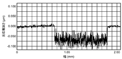
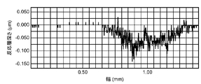
- . 7 to 8 are diagrams showing the results of measuring the surface shape of the reaction layer 7 of the glass substrate in the reflecting mirror 1 produced in Examples 1 and 2 described later. As shown in these figures, after the reaction layer 7 is dissolved and removed from the first and second glass substrates 2 and 3, the surface shapes of the first and second glass substrates 2 and 3 are measured with a surface roughness meter. By doing so, the shape of the reaction layer 7 can be evaluated.
- the sealing glass layer 5 is made of a molten and solidified body of a sealing glass material containing a low melting point glass which is an essential component and an inorganic filler which is an optional component.
- the combination, blending amount, and the like of the sealing glass material are selected in consideration of the compatibility with the first and second glass substrates 2 and 3 and the respective characteristics.
- the sealing glass material preferably contains at least a low melting glass, and its content is preferably 60 to 100% by volume.
- the content of the inorganic filler as an optional component is preferably 0 to 40% by volume. When the content of the low-melting glass is less than 60% by volume, the fluidity of the sealing glass material at the time of sealing is lowered, and there is a possibility that good sealing cannot be performed.
- the content of the low melting point glass is more preferably 65% by volume or more.
- the upper limit is not particularly limited, but it is preferably 97% by volume or less, and more preferably 90% by volume or less in consideration of adjustment of the coefficient of thermal expansion with respect to the glass substrates 2 and 3.
- the low melting point glass for example, tin-phosphate glass, bismuth glass, vanadium glass, lead glass, silica alkali borate glass and the like are used.
- bismuth-based glass may be used in consideration of adhesion to the glass substrates 2 and 3 and reliability thereof (for example, adhesion reliability and hermetic sealing), and influence on the environment and human body. preferable.
- the bismuth glass as the low melting point glass is 70 to 90% Bi 2 O 3 , 1 to 20% ZnO, 2 to 12% B in terms of mass percentage or mass percentage in the following oxide conversion notation. It preferably has a composition containing 2 O 3 and 10-1000 ppm of Na 2 O. Glass formed of three components of Bi 2 O 3 , ZnO, and B 2 O 3 is suitable for a low-melting glass of a sealing glass material because it has characteristics such as transparency and low glass transition point.
- reaction layer 7 is easily generated at the bonding interface between the first and second glass substrates 2 and 3 and the sealing glass layer 5.
- Bi 2 O 3 is a component that forms a glass network, and is preferably contained in the sealing glass in a range of 70 to 90% by mass.
- the content of Bi 2 O 3 is less than 70% by mass, the softening temperature of the low-melting glass becomes high.
- the content of Bi 2 O 3 exceeds 90% by mass, it becomes difficult to vitrify, it becomes difficult to produce glass, and the thermal expansion coefficient tends to be too high.
- the Bi 2 O 3 content is more preferably in the range of 78 to 87% by mass.
- ZnO is a component that lowers the thermal expansion coefficient and softening temperature, and is preferably contained in the low melting point glass in the range of 1 to 20% by mass. Vitrification becomes difficult when the content of ZnO is less than 1% by mass. If the content of ZnO exceeds 20% by mass, the stability at the time of molding a low-melting glass is lowered, devitrification is likely to occur, and glass may not be obtained. Considering the stability of glass production, the ZnO content is more preferably in the range of 7 to 12% by mass.
- B 2 O 3 is a component that increases the range in which vitrification is possible by forming a glass skeleton, and is preferably contained in the range of 2 to 12% by mass in the low-melting glass. If the content of B 2 O 3 is less than 2% by mass, vitrification becomes difficult. The content of B 2 O 3 is higher softening point exceeds 12 mass%. In consideration of the stability of the glass, the sealing temperature, etc., the content of B 2 O 3 is more preferably in the range of 5 to 10% by mass.
- Na 2 O is a component that increases the reactivity of the low-melting glass of the sealing glass material layer 8 with respect to the first and second glass substrates 2 and 3, and is contained in the low-melting glass in a mass ratio of 10 to 1000 ppm. It is preferable to make it.
- the content of Na 2 O is less than 10 ppm, the generation efficiency of the reaction layer 7 cannot be sufficiently increased. If the content of Na 2 O exceeds 1000 ppm, the stability of the glass is impaired, and devitrification tends to occur.
- the content of Na 2 O is in the range of 100 to 1000 ppm by mass. More preferably.
- Li 2 O and K 2 O also function as components for forming the reaction layer 7 at the adhesive interface between the first and second glass substrates 2 and 3 and the sealing glass layer 5.
- Na 2 O which is particularly excellent in reactivity with the glass substrates 2 and 3 is effective, and therefore the bismuth-based glass preferably contains Na 2 O.
- a part of Na 2 O may be substituted with at least one selected from the group consisting of Li 2 O and K 2 O.
- the amount of substitution of Na 2 O by Li 2 O or K 2 O is preferably 50% by mass or less of the amount of Na 2 O in consideration of the formability of the reaction layer 7 at the adhesion interface.
- Bismuth glass formed by 4 components described above has a low glass transition point, but is suitable for sealing material, Al 2 O 3, CeO 2 , SiO 2, Ag 2 O, WO 3, MoO 3,
- Optional components such as Nb 2 O 3 , Ta 2 O 5 , Ga 2 O 3 , Sb 2 O 3 , Cs 2 O, CaO, SrO, BaO, P 2 O 5 , SnO x (x is 1 or 2) May be contained.
- the content of any component is too large, the glass becomes unstable and devitrification may occur, or the glass transition point and softening point may increase, so the total content of any component is 10% by mass or less.
- the lower limit of the total content of arbitrary components is not particularly limited. An effective amount of an arbitrary component can be blended with the bismuth glass based on the purpose of addition.
- Al 2 O 3 , SiO 2 , CaO, SrO, BaO and the like are components that contribute to glass stabilization, and the content thereof is preferably in the range of 0 to 7% by mass.
- BaO is excellent in the contribution of stabilization, and can be contained as the fifth component in the range of 0.1 to 7% by mass.
- Cs 2 O has an effect of lowering the softening temperature of the glass
- CeO 2 has an effect of stabilizing the fluidity of the glass.
- Ag 2 O, WO 3 , MoO 3 , Nb 2 O 3 , Ta 2 O 5 , Ga 2 O 3 , Sb 2 O 3 , P 2 O 5 , SnO x and the like adjust the viscosity and thermal expansion coefficient of the glass. It can be contained as a component.
- the content of each of these components can be appropriately set within a range where the total content of arbitrary components does not exceed 10% by mass (including 0% by mass).
- Examples of the inorganic filler blended as an optional component in the sealing glass material include a thermal expansion adjusting material and an electromagnetic wave absorbing material.
- the thermal expansion adjusting material approximates the thermal expansion coefficient between the first and second glass substrates 2 and 3 and the sealing glass layer 5.
- the thermal expansion coefficient of the low-melting glass is larger than that of the first and second glass substrates 2 and 3, so that the inorganic filler (that is, the thermal expansion coefficient is smaller than that of the first and second glass substrates 2 and 3).
- Low expansion fillers are often used.
- an inorganic filler it is preferable to use at least one selected from the group consisting of silica, alumina, zirconia, zirconium silicate, cordierite, zirconium phosphate compound, soda lime glass, and borosilicate glass.
- zirconium phosphate-based compound examples include (ZrO) 2 P 2 O 7 , NaZr 2 (PO 4 ) 3 , KZr 2 (PO 4 ) 3 , Ca 0.5 Zr 2 (PO 4 ) 3 , and NbZr (PO 4 ). 3 , Zr 2 (WO 3 ) (PO 4 ) 2 , and composite compounds thereof.
- the content of the inorganic filler is preferably 0 to 40% by mass.
- the preferable lower limit of the content of the inorganic filler is 3% by volume or more, more preferably 10% by volume or more.
- the electromagnetic wave absorbing material is a filler that enhances the electromagnetic wave absorbing ability of the sealing glass material when the sealing glass material is heated by irradiating an electromagnetic wave such as laser light or infrared light.
- an electromagnetic wave such as laser light or infrared light.
- the electromagnetic wave absorber at least one metal selected from the group consisting of Fe, Cr, Mn, Co, Ni, and Cu, or a compound such as an oxide containing the metal is used. Other pigments may be used.
- the content of the electromagnetic wave absorbing material is preferably in the range of 0 to 40% by volume.
- the content of the electromagnetic wave absorbing material exceeds 40% by volume, the fluidity at the time of melting of the sealing glass material is lowered, and there is a possibility that the sealing cannot be performed satisfactorily.
- content of an electromagnetic wave absorber 25 volume% or less is more preferable, More preferably, it is 20 volume% or less.
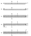
- the reflecting mirror 1 of this embodiment is manufactured as follows, for example. First, the manufacturing process of the reflecting mirror 1 using a baking furnace will be described with reference to FIG. First, as illustrated in FIG. 9A, the reflective film 4 is formed on the surface 2 a of the first glass substrate 2.
- the reflective film 4 may be formed in a desired shape excluding the region where the sealing glass layer 5 is formed, or after being formed on the entire surface 2a, the region where the sealing glass layer 5 is formed is trimmed. And it is good also as a desired shape.
- a sealing glass material layer 8 is formed in the outer peripheral region (sealing region) of the surface 3 a of the second glass substrate 3.
- the sealing glass material layer 8 is prepared by mixing a low melting glass, which is an essential component of the sealing glass material, and an inorganic filler, which is an optional component, with a vehicle to prepare a sealing glass material paste. It forms by apply
- the vehicle is obtained by dissolving a resin as a binder component in a solvent.
- the resin for the vehicle include cellulose resins such as methyl cellulose, ethyl cellulose, carboxymethyl cellulose, oxyethyl cellulose, benzyl cellulose, propyl cellulose, nitrocellulose, methyl methacrylate, ethyl methacrylate, butyl methacrylate, 2-hydroxyethyl methacrylate, butyl acrylate, An organic resin such as an acrylic resin obtained by polymerizing at least one acrylic monomer such as 2-hydroxyethyl acrylate is used.
- terpineol, butyl carbitol acetate, ethyl carbitol acetate or the like is used in the case of a cellulose resin, and methyl ethyl ketone, terpineol, butyl carbitol acetate, ethyl carbitol acetate or the like is used in the case of an acrylic resin.
- the viscosity of the sealing glass material paste may be adjusted to the viscosity corresponding to the apparatus applied to the glass substrate 3, and can be adjusted by the ratio of the resin and the solvent, the ratio of the sealing glass material and the vehicle.
- the resin is a component that disappears upon firing.
- You may add a well-known additive with a glass paste like an antifoamer and a dispersing agent to sealing glass material paste. These additives are also components that usually disappear during firing.
- a known method using a rotary mixer equipped with a stirring blade, a roll mill, a ball mill, or the like can be applied.
- the sealing glass material paste is applied to the outer peripheral region of the second glass substrate 3 over the entire circumference and dried to form a coating film of the sealing glass material paste.
- the sealing glass material paste is applied to the outer peripheral region by applying a printing method such as screen printing or gravure printing, or is applied along the outer peripheral region using a dispenser or the like.
- the width of the coating film is preferably 0.5 to 20 mm in order to maintain the strength.
- the thickness of the coating film is set according to the thickness of the hermetic space between the first glass substrate 2 and the second glass substrate 3, taking into account the shrinkage of the film in the subsequent drying process or pre-baking process. It is preferable to set. For example, the thickness of the coating film is set so that the thickness of the sealing glass layer after sealing is 1 to 50 ⁇ m.
- the coating film of the sealing glass material paste is preferably dried at a temperature of 60 to 150 ° C. for 30 seconds to 10 minutes, for example, to remove the solvent in the coating film. Subsequently, after heating to a temperature lower by 30 ° C. or lower than the glass transition point of the low-melting glass in a firing furnace to remove the binder component and the like in the coating film, the temperature is higher than the softening point of the low-melting glass (for example, By heating the sealing glass material to the second glass substrate 3 to form a frame-shaped sealing glass material layer 8 on the outer peripheral region of the second glass substrate 3. Form.
- the glass transition point is defined by the temperature of the first inflection point of differential thermal analysis (DTA), and the glass softening point is defined by the temperature of the fourth inflection point of differential thermal analysis (DTA).
- the first glass substrate 2 and the second glass substrate 3 are opposed to the surface 2 a having the reflective film 4 and the surface 3 a having the sealing glass material layer 8.
- the atmosphere during firing is preferably a vacuum or an inert gas atmosphere such as nitrogen gas or argon gas in order to suppress the deterioration of the reflective film 4.
- the state in the space 6 hermetically sealed with the first glass substrate 2, the second glass substrate 3, and the sealing glass layer 5 is determined according to the atmosphere during firing. Moreover, when installing a spacer in the airtight space 6, when laminating
- reaction layer 7 is formed at the interface between the first and second glass substrates 2 and 3 and the sealing glass layer 5.
- the formation state of the reaction layer 7 depends on the composition of the low melting point glass in the sealing glass material layer 8, the firing temperature, the adhesion between the sealing glass material layer 8 and the first glass substrate 2, and the like.
- the higher the firing temperature the easier the formation of the reaction layer 7 proceeds.
- Adhesion can be improved by applying a load with a heat-resistant clip or weight.
- the reflective film 4 is formed on the surface 2 a of the first glass substrate 2.
- the formation process of the reflective film 4 is the same as the manufacturing process using a baking furnace.
- the sealing glass material layer 8 is formed in the outer peripheral region (sealing region) of the surface 3 a of the second glass substrate 3.
- the forming process of the sealing glass material layer 8 is performed in the same manner as the manufacturing process using the firing furnace except that the sealing glass material includes an electromagnetic wave absorbing material.
- the sealing glass material layer 8 is irradiated with an electromagnetic wave 9 such as a laser beam or an infrared ray through the second glass substrate 3 (or the first glass substrate 2).
- an electromagnetic wave 9 such as a laser beam or an infrared ray through the second glass substrate 3 (or the first glass substrate 2).
- the laser beam is irradiated while scanning along the sealing glass material layer 8.
- the laser light is not particularly limited, and laser light from a semiconductor laser, carbon dioxide laser, excimer laser, YAG laser, HeNe laser, or the like is used.
- the electromagnetic wave 9 When infrared rays are used as the electromagnetic wave 9, for example, a portion other than a portion where the sealing glass material layer 8 is formed is masked with an infrared reflecting film such as Ag, and the sealing glass material layer 8 can be selectively irradiated with infrared rays. preferable.
- an infrared reflecting film such as Ag
- the sealing glass material layer 8 When a laser beam is used as the electromagnetic wave 9, the sealing glass material layer 8 is melted in order from the portion irradiated with the laser beam scanned along it, and is rapidly cooled and solidified upon completion of the laser beam irradiation. It adheres to the substrate 2. Then, by irradiating the entire circumference of the sealing glass material layer 8 with laser light, as shown in FIG. 10 (e), the entire circumference is provided between the first glass substrate 2 and the second glass substrate 3. A sealing glass layer 5 that is sealed over is formed.
- the sealing glass material layer 8 is melted based on infrared irradiation, and is rapidly cooled and solidified and fixed to the first glass substrate 2 upon completion of infrared irradiation. As shown in FIG. 10 (e), a sealing glass layer 5 that seals between the first glass substrate 2 and the second glass substrate 3 over the entire circumference is formed.
- the heating temperature of the sealing glass material layer 8 by the electromagnetic wave 9 such as laser light or infrared is set to be equal to or higher than the softening point of the low melting point glass.
- the heating temperature is preferably (T + 200 ° C.) or more and (T + 800 ° C.) or less with respect to the softening point T (° C.) of the low-melting glass.
- the heat of the sealing glass material layer 8 is dissipated to the outside through the glass substrates 2 and 3.
- the transmission efficiency is low.
- the reaction between the glass substrates 2 and 3 and the low-melting glass tends to proceed in the vicinity of the center of the sealing glass material layer 9 where heat does not easily escape. Therefore, when local heating by laser light or infrared rays is applied, the reaction layer 7 having a shape as shown in FIGS. 5 and 6 is easily generated.
- laser light is used as the electromagnetic wave 9, it is preferable to use laser light having a protruding intensity distribution, and the reaction layer 7 is also likely to have a concave shape.
- the atmosphere at the time of irradiation with the electromagnetic wave 9 is preferably a vacuum or an inert gas atmosphere such as nitrogen gas or argon gas in order to suppress deterioration of the reflective film 4.
- a vacuum or an inert gas atmosphere such as nitrogen gas or argon gas
- the active gas is filled.
- the resin is filled in the space 6, the second glass substrate 3 and the first glass substrate 2 coated with the resin are laminated inside the sealing glass material layer 8, and the electromagnetic wave 9 is irradiated in this state. do it.
- a spacer is arrange
- Example 1 As a low melting point glass, the composition of Bi 2 O 3 83.2%, B 2 O 3 5.6%, ZnO 10.7%, Al 2 O 3 0.5% in the mass percentage of the following oxide conversion notation A bismuth glass frit (softening point: 410 ° C.) having an average particle size (D 50 ) of 100 ppm Na 2 O in mass parts per million and an inorganic filler (low expansion) As a filler, cordierite powder having an average particle size (D 50 ) of 4.3 ⁇ m was prepared.
- Particle size distribution was measured using a particle size analyzer (Nikkiso Co., Ltd., Microtrac HRA) using a laser diffraction / scattering method.
- the measurement conditions were as follows: measurement mode: HRA-FRA mode, Particle Transparency: yes, Special Particles: no, Particle Refractive index: 1.75, Fluid Refractive index: 1.33.
- a sealing glass material was prepared by mixing 67.5% by volume of the above-described bismuth glass frit and 32.5% by volume of cordierite powder. 17% by mass of a vehicle prepared by dissolving 83% by mass of this sealing glass material and 5% by mass of ethyl cellulose as a resin binder component in 95% by mass of 2,2,4-trimethyl-1,3-pentanediol monoisobutyrate And a sealing material paste was prepared.
- a second glass substrate (size: 100 mm ⁇ 100 mm ⁇ 2.8 mm) made of soda lime glass is prepared, and a sealing glass material paste is applied to the entire circumference of the outer peripheral region of the glass substrate by a screen printing method. After obtaining the coating film, it was dried at 120 ° C. for 10 minutes to form a sealing glass material layer.
- the printing pattern of the sealing glass material paste was a frame pattern having a line width of 0.5 mm, the size of the area of the glass substrate inside the coating film was 70 mm ⁇ 70 mm, and the curvature radius R of the corner portion was 2 mm.
- the coating film is heated under conditions of 300 ° C. ⁇ 30 minutes to remove the resin binder component, and then fired under conditions of 480 ° C. ⁇ 10 minutes to form a sealing glass material layer having a thickness of 15 ⁇ m. did.
- a silver thin film was formed as a reflective film on the surface of the first glass substrate (substrate made of soda lime glass having the same composition and shape as the second glass substrate) by spray coating.
- the peripheral edge of the silver thin film is arranged such that the peripheral edge thereof is disposed inside the sealing glass material layer formed on the second glass substrate (that is, it does not overlap the sealing glass material layer).
- the part was trimmed using a 30% aqueous nitric acid solution.
- palladium was not deposited on the surface of the first glass substrate by an activation treatment using a solution containing a palladium compound as a catalyst for forming a silver thin film. Therefore, when the Pd concentration on the surface of the first glass substrate was measured according to the method described above, it was confirmed that it was below the detection limit (0.10 atomic%).
- the above-mentioned second glass substrate having the sealing glass material layer and the first glass substrate having a silver thin film are laminated so that the sealing glass material layer and the silver thin film face each other, and the The two glass substrates and the first glass substrate were sandwiched, and the two glass substrates were put into close contact with each other and placed in a firing furnace. And the 1st glass substrate and the 2nd glass substrate were sealed by baking on 480 degreeC * 10 minute conditions in nitrogen gas atmosphere, and the sealing glass layer was obtained. The characteristics of the reflecting mirror thus obtained were evaluated.
- Example 2 It has a composition of Bi 2 O 3 83.2%, B 2 O 3 5.6%, ZnO 10.7%, Al 2 O 3 0.5% by mass percentage in the following oxide conversion notation, and further mass Bismuth glass frit (softening point: 410 ° C.) containing 150 ppm Na 2 O in parts per million and having an average particle size (D 50 ) of 1.0 ⁇ m, and an average particle as an inorganic filler (low expansion filler)
- a sealing glass material was prepared by mixing 66.8% by volume of the bismuth-based glass frit described above, 32.2% by volume of cordierite powder, and 1.0% by volume of the electromagnetic wave absorber. 17% by mass of a vehicle prepared by dissolving 83% by mass of this sealing glass material and 5% by mass of ethyl cellulose as a resin binder component in 95% by mass of 2,2,4-trimethyl-1,3-pentanediol monoisobutyrate And a sealing material paste was prepared.
- a second glass substrate (size: 100 mm ⁇ 100 mm ⁇ 2.8 mm) made of soda lime glass is prepared, and a sealing glass material paste is applied to the entire circumference of the outer peripheral region of the glass substrate by a screen printing method. After obtaining the coating film, it was dried at 120 ° C. for 10 minutes to form a sealing glass material layer.
- the printing pattern of the sealing glass material paste was a frame-like pattern with a line width of 0.5 mm, the size of the region of the glass substrate inside the coating film was 70 mm ⁇ 70 mm, and the curvature radius R of the corner portion was 2 mm.
- the coating film is heated under conditions of 300 ° C. ⁇ 30 minutes to remove the resin binder component, and then fired under conditions of 480 ° C. ⁇ 10 minutes to form a sealing glass material layer having a thickness of 15 ⁇ m. did.
- a silver thin film was formed as a reflective film on the surface of the first glass substrate (substrate made of soda lime glass having the same composition and shape as the second glass substrate) by spray coating.
- the peripheral edge of the silver thin film is arranged such that the peripheral edge thereof is disposed inside the sealing glass material layer formed on the second glass substrate (that is, it does not overlap the sealing glass material layer).
- the part was trimmed using a 30% aqueous nitric acid solution.
- a small amount of palladium was deposited on the surface of the first glass substrate by an activation treatment using a solution containing a palladium compound as a catalyst for forming a silver thin film. Therefore, when the Pd concentration on the surface of the first glass substrate was measured according to the method described above, it was confirmed to be 0.13 atomic%.
- the second glass substrate having the above-described sealing glass material layer and the first glass substrate having a silver thin film were laminated so that the sealing glass material layer and the silver thin film faced each other.
- a laser beam having a wavelength of 808 nm, an output of 70 W, and a spot diameter of 3.0 mm is applied to the sealing glass material layer through the second glass substrate in a state where a pressure of 0.25 MPa is applied from the second glass substrate.
- semiconductor laser is irradiated at a scanning speed of 4 mm / sec to melt and rapidly cool and solidify the sealing glass material layer, thereby sealing the first glass substrate and the second glass substrate, and sealing glass layer Got.
- the heating temperature (measured with a radiation thermometer) of the sealing glass material layer when irradiated with laser light was 620 ° C. The characteristics of the reflecting mirror thus obtained were evaluated.
- a silver thin film was formed as a reflective film on the surface of a glass substrate (dimensions: 100 mm ⁇ 100 mm ⁇ 4 mm) made of soda lime glass by a spray coating method. Subsequently, a copper thin film was spray-coated on the silver thin film with a thickness of about 0.03 ⁇ m, and an epoxy resin protective film was further coated with a thickness of 45 ⁇ m to produce a reflecting mirror.
- palladium was deposited on the surface of the glass substrate as a catalyst by an activation treatment using a solution containing a palladium compound. Therefore, when the Pd concentration on the surface of the glass substrate was measured according to the method described above, it was 0.20 atomic%.
- the resin protective film cannot suppress deterioration of the silver thin film.
- a silver thin film was formed as a reflective film on the surface of a glass substrate (dimensions: 100 mm ⁇ 100 mm ⁇ 4 mm) made of soda lime glass by a spray coating method. Conditions of 120 ° C. ⁇ 40 minutes by sandwiching a polyvinyl butyral film having a thickness of 0.38 mm between a glass substrate on which a silver thin film is formed and a glass substrate made of soda lime glass (dimensions: 100 mm ⁇ 100 mm ⁇ 2.8 mm) By heating with, a reflecting mirror in the form of a laminated glass was produced.
- the configuration of the reflecting mirror of the present invention has been described using the expressions of the first glass substrate and the second glass substrate.
- the first glass substrate is used as the second glass substrate.
- the second glass substrate may be replaced with the first glass substrate, and the present invention is the same.
- the glass substrate surface is excellent in water resistance without being subjected to palladium metal treatment, and deterioration of the reflective film due to moisture or the like can be suppressed over a long period of time, and the reflectance is reduced. Can be obtained at low cost.
- a reflector is useful as a reflector used in a solar heat collector, a solar light collecting system, or the like.
Landscapes
- Physics & Mathematics (AREA)
- General Physics & Mathematics (AREA)
- Optics & Photonics (AREA)
- Joining Of Glass To Other Materials (AREA)
- Optical Elements Other Than Lenses (AREA)
- Mounting And Adjusting Of Optical Elements (AREA)
Abstract
耐水性に優れ、かつ反射率を向上させつつ、製造コストを低減することを可能にした反射鏡を提供する。 反射鏡1は、第1の表面2aを有する第1のガラス基板2と、第1のガラス基板2の第1の表面2aに形成された反射膜4と、第1の表面2aと対向する第2の表面3aを有し、第1のガラス基板2と所定の間隙をもって配置された第2のガラス基板3と、反射膜4を気密封止するように、第1のガラス基板2と第2のガラス基板3との間に形成された封着ガラス層5とを具備する。第1のガラス基板2の第1の表面2aにおけるPd濃度は0.15原子数%以下とされている。
Description
本発明は、反射鏡に関する。
近年、太陽光を集光して得られる熱エネルギーを利用する装置やシステムが注目されており、太陽光集熱器や太陽光集光システムの開発および実用化が進められている。例えば、太陽光を集光し、その熱エネルギーにより高温および高圧の蒸気を発生させ、その蒸気を用いてタービンを駆動する太陽熱発電システム等が検討されている。太陽光集熱器や太陽光集光システム等においては、一般的に太陽光の集光効率を高めるために、反射鏡が用いられている。反射鏡は、ガラス基板等の透明基板上にアルミニウムや銀等の金属薄膜を反射膜としてコーティングすることにより作製される。
透明基板上に金属薄膜をコーティングした反射鏡は、表面の金属薄膜が環境雰囲気中の水分や酸素等により劣化しやすいという問題を有している。このような金属薄膜を保護するために、金属薄膜上にアクリル樹脂やエポキシ樹脂等からなる保護膜を形成した反射鏡が知られている。しかしながら、樹脂による保護膜は耐水性が不充分であるため、屋外に設置した際に長期間にわたって金属薄膜の劣化を防ぐことは難しい。
特許文献1には、合わせガラス鏡の全周縁に沿ってシリコーンシーラント等からなる弾性シール剤を被覆した反射鏡が記載されている。特許文献2には、ガラス基板上に銀鏡膜と銅等からなる金属保護膜と裏止め塗膜とを順に積層すると共に、これらの積層膜の端縁にアクリルシリコーン樹脂からなる被膜を形成した反射鏡が記載されている。しかし、シリコーンシーラントやアクリルシリコーン樹脂等の水バリア性は完全ではなく、長期間にわたって耐水性を維持することは難しい。また、金属保護膜は非常に薄いことから、熱膨張等により徐々にクラックが入りやすく、信頼性に乏しいという難点を有している。
さらに、銀膜等の金属薄膜をガラス基板上に形成するにあたって、水分の侵入による銀膜の劣化や剥離等を抑制するために、ガラス基板上にパラジウム化合物を含有する溶液による活性化処理によってパラジウム(Pd)を銀膜の下地として被着し、これによりガラス基板と銀膜との密着性を高めることが行われている。しかしながら、下地層としてのパラジウムは非常に高価であるため、反射鏡の製造コストを増加させる原因となっている。また、下地層としてパラジウムを被着させると、銀膜自体の反射率を低下させるため、反射鏡の性能を低下させる要因ともなっている。
本発明の目的は、耐水性に優れ、かつ反射率を向上させつつ、製造コストを低減することを可能にした反射鏡を提供することにある。
本発明の反射鏡は、第1の表面を有する第1のガラス基板と、前記第1のガラス基板の前記第1の表面に形成された反射膜と、前記第1の表面と対向する第2の表面を有し、前記第1のガラス基板と所定の間隙をもって配置された第2のガラス基板と、前記反射膜を気密封止するように、前記第1のガラス基板と前記第2のガラス基板との周辺部に、かつ前記第1のガラス基板と前記第2のガラス基板との間に形成された封着ガラス層とを具備し、前記第1のガラス基板の前記第1の表面におけるPd濃度が0.15原子数%(atomic percent)以下であることを特徴としている。
本発明の反射鏡は、第1のガラス基板と第2のガラス基板との間を耐水性に優れる封着ガラス層で気密封止しているため、反射膜の水分等による劣化を長期間にわたって抑制できる。従って、反射膜の下地としてのPd濃度を低減した場合においても、反射膜の劣化や剥離等を抑制できる。本発明によれば、優れた反射率を長期間にわたって維持することが可能な反射鏡を低コストで提供できる。
以下、本発明を実施するための形態について、図面を参照して説明する。図1は第1の実施形態による反射鏡の構成を示す断面図であり、図2は第2の実施形態による反射鏡の構成を示す断面図である。これらの図に示す反射鏡1は、第1の表面2aを有する第1のガラス基板2と、第2の表面3aを有する第2のガラス基板3とを具備している。第1のガラス基板2と第2のガラス基板3とは、第1の表面2aと第2の表面3aとが対向するように、所定の間隙をもって積層配置されている。
第1の実施形態による反射鏡1は、第1のガラス基板2の表面2aに形成された反射膜4を有している。反射膜4は、銀、銀合金(Ag-Pt合金、Ag-Pd合金等)、アルミニウム等の金属からなる。このような金属からなる反射膜(金属反射膜)4は、蒸着法、スパッタリング法、CVD法、イオンプレーティング法、イオンビーム照射法、スプレーコート法等の各種薄膜形成法により形成できる。
反射膜4は、第1のガラス基板2の表面2aのみに限らず、第2のガラス基板3の表面3aに形成してもよい。第2の実施形態による反射鏡1は、第1のガラス基板2の表面2aに形成された第1の反射膜4Aと、第2のガラス基板3の表面3aに形成された第2の反射膜4Bとを有している。第2のガラス基板3の表面3aにも反射膜4Bを形成することによって、第1のガラス基板2と第2のガラス基板3の両面を反射面として使用できる。例えば、まず反射面として使用した第1のガラス基板2の外表面が傷つき、乱反射や吸収により反射率が低下した場合に、反射鏡1を反転させ、第2のガラス基板3を反射面として使用することによって、反射鏡1の寿命をさらに延ばすことが可能となる。
第1のガラス基板2の外周領域と第2のガラス基板3の外周領域との間には、その全周に渡り、反射膜4、または反射膜4Aおよび4B(以下、反射膜4、反射膜4Aおよび4Bを含め、反射膜4と称することもある。)を気密封止するように封着ガラス層5が形成されている。すなわち、反射鏡4は、第1のガラス基板2と第2のガラス基板3と封着ガラス層5とで構成されたガラスパッケージの気密空間6内に位置されている。封着ガラス層5は、必須成分として低融点ガラスを含んでおり、また後に詳述するように、任意成分として熱膨張調整材や電磁波吸収材等の無機充填材を含んでいてもよい。封着ガラス層5は、必須成分としての低融点ガラスと任意成分としての無機充填材と含む封着ガラス材料の溶融固化体からなる。
封着ガラス層5は実質的に無機材料のみで構成されているため、従来の有機材料による封止材に比べて気密性に優れ、かつ反射膜4の劣化原因となる水分等の侵入を長期間にわたって阻止できる。これは封着ガラス層5で反射膜4の劣化や剥離等を抑制できることを意味する。従って、従来のように、反射膜4の耐久性向上のために、反射膜4の下地としてパラジウム(Pd)を被着することなく、反射膜4の第1のガラス基板2、第2のガラス基板3に対する密着性を長期間にわたって維持することが可能となる。また、反射膜4の形成時における均質性の向上(ムラの抑制等)のために、触媒としてパラジウムを被着する場合においても、その量は極微量とすることができる。つまり、反射膜4の密着性の向上等を考慮することなく、反射膜4をムラのなく形成することが可能な量のパラジウムを被着すればよい。
このため、実施形態の反射鏡1においては、反射膜4(または4A)の形成面となる第1のガラス基板2の表面2aのパラジウム(Pd)濃度、また第2のガラス基板3にも反射膜4Bを形成する場合には第2のガラス基板2の表面3aのパラジウム(Pd)濃度を、0.15原子数%以下としている。ここにおいて、パラジウム(Pd)濃度が、0.15原子数%以下とは、パラジウム(Pd)濃度が、0.00原子数%の場合も含む。ガラス基板2、またはガラス基板2および3の表面2a、または表面2aおよび3aのPd濃度を0.15原子数%以下とすることによって、反射膜1の製造コストを低減できる。さらに、パラジウムによる反射膜4の反射率の低下を抑制することが可能となる。従って、優れた反射率を長期間にわたって維持することが可能な反射鏡1を提供でき、さらにそのような反射鏡1の製造コストを低減することが可能となる。
ここで、前記したガラス基板の表面のPd濃度は、以下のようにして求めた値を示す。すなわち、ガラス基板の表面におけるPd濃度の測定は、Arイオンビームによるスパッタエッチングを併用したX線光電子分光法(XPS)を用い、表面からの深さ方向分析により行う。より具体的には、Pd、Ag、Sn、Si、Na、Oの元素の深さ方向分析を行い、図3に示すような深さ方向の濃度グラフを作成する。次いで、図4に拡大して示すように、Pd3dのXPSピーク強度が最大となる点(図4のA点)における濃度をPd濃度(原子数%)とする。
ここで、各元素の測定は以下のエネルギー範囲で実施する。Pd3dは330~348eV、Ag3dは364~380eV、Sn3d5/2は480~500eV、Si2pは95~110eV、Na1sは1066~1082eV、O1sは525~540eVとする。定量は、アルバック・ファイ社製PHI MultiPakデータ解析用ソフトウェアTM Ver.8.2(商品名)を用いて行った。定量には、Shirley法を用いてバックグラウンドを差し引き、5ポイントSavitzky-Golayスムージングを3回繰り返したスペクトルを用いた。
上記した手法では、Arイオンビームによるスパッタエッチング時間が表面からの深さ、つまり膜厚に対応する。スパッタエッチング時間から膜厚への換算は、膜厚が既知でかつ同じ組成の標準試料を用いて作成した検量線より求めた。すなわち、SiO2換算で0.5nm/minとして算出した。使用したXPS分光装置はファイ社製5500型であり、モノクロメータで単色化したX線AlKα線をX線源とした。また、X線光電子の検出角は45°であり、帯電補正のために電子シャワーを照射して測定を実施した。測定条件は、パスエネルギー:117.4eV、ステップエネルギー:0.5eVとし、エネルギー分解能はAg3d5/2の半値幅で1.70eVで行った。Arスパッタリングは、加速エネルギー1kVにて3×3mm2の領域に対して実施した。
さらに、反射膜4の表面には、耐久性を向上させるための金属膜や樹脂膜からなる保護膜等が形成されていなくてもよい。すなわち、反射膜4は第1のガラス基板2と第2のガラス基板3と封着ガラス層5とで気密封止された空間6内に露出している。反射膜4の表面に保護膜等が形成されていなくても、第1のガラス基板2と第2のガラス基板3と封着ガラス層5とで構成されたガラスパッケージは気密封止性に優れている。したがって、反射膜の下地としてPd濃度を低減した場合においても、反射膜4の劣化や剥離等を抑制できる。さらに、反射膜4上への保護膜の形成を省くことによっても、反射鏡1の製造コストを低減できる。なお、後述するようにガラスパッケージによる気密空間6には、樹脂等を充填してもよい。このような場合において、反射膜4の気密空間6への露出は、充填物を除いて、反射膜4上に他の膜や部材等が存在していないことを意味する。
次に、この実施形態の反射鏡1を構成する各部材や詳細構造等について述べる。第1及び第2のガラス基板2、3は、各種公知の組成を有するソーダライムガラス、無アルカリガラス、化学強化ガラス、物理強化ガラス等で構成される。ソーダライムガラスは80~90(×10-7/℃)程度の熱膨張係数を有している。無アルカリガラスは35~40(×10-7/℃)程度の熱膨張係数を有している。高い反射率を得るという観点からソーダライムガラスは、透明度が高い白板ガラス(高透過ガラス)が好ましい。ここでいう白板ガラス(高透過ガラス)とは、可視光透過率が普通のソーダライムガラスよりも高く、90%以上の可視光透過率を有するガラスであり、例えば、普通のソーダライムガラスに対し鉄分をFe2O3として0.06%以下としたガラスである。ソーダライムガラスを化学強化や物理強化した強化ガラスは、反射鏡1の強度や信頼性等を高める上で好ましい。強化ガラスはソーダライムガラス以外のガラスを化学強化や物理強化したものであってもよい。
上記した数値範囲を示す「~」とは、特段の定めがない限り、その前後に記載された数値を下限値及び上限値として含む意味で使用され、以下本明細書において「~」は、同様の意味をもって使用される。
上記した数値範囲を示す「~」とは、特段の定めがない限り、その前後に記載された数値を下限値及び上限値として含む意味で使用され、以下本明細書において「~」は、同様の意味をもって使用される。
第1及び第2のガラス基板2、3の厚さは0.03~5mmの範囲であることが好ましい。ガラス基板2、3の厚さが0.03mm未満であると、反射鏡1の強度や信頼性が不充分になるおそれがある。一方、ガラス基板2、3の厚さが5mmを超えると、反射鏡1が重くなるだけでなく、ガラス基板自体の吸収により反射率も低下するおそれがある。反射鏡1の反射率や重さを考慮すると、ガラス基板2、3の厚さは薄い方が望ましく、具体的には0.03~2.8mmがより好ましく、さらに好ましくは0.03~1.1mmである。反射鏡1の強度を考慮すると、ガラス基板2、3の厚さは厚い方が望ましく、具体的には0.07~5mmがより好ましく、さらに好ましくは1.1~5mmである。
第1及び第2のガラス基板2、3の厚さは、反射膜4の形成箇所によっても適宜に調整することが好ましい。すなわち、第1のガラス基板2の表面2aのみに反射膜4を形成する場合、第1のガラス基板2の厚さは0.03~0.7mmが好ましく、第2のガラス基板3の厚さは0.7~5mmが好ましい。これによって、反射鏡1の反射率を高めつつ、強度の向上を図ることができる。第1のガラス基板2の表面2aと第2のガラス基板3の表面3aの両方に反射膜4を形成する場合、反射鏡1の反射率と強度とを考慮して、第1及び第2のガラス基板2、3の厚さは0.55~2.8mmが好ましい。
図1及び図2に示す反射鏡1は、平板形状のガラス基板2、3を有している。ガラス基板2、3の形状はこれに限られるものではなく、湾曲形状を有していてもよい。湾曲形状を有するガラス基板を用いた反射鏡は、例えばトラフ型太陽光発電のような曲面鏡で太陽光を集光させる方式に好適である。これ以外にも、太陽光を集光させる場合に湾曲形状を有するガラス基板を用いた反射鏡は有効である。
第1のガラス基板2と第2のガラス基板3と封着ガラス層5とで構成されたガラスパッケージの内部空間(すなわち、気密空間)6は、空気が充填された状態であってもよい。しかし、空気中の酸素と反射膜4との反応、またガラス基板2、3と封着ガラス層5との接合界面に対する空気中の酸素の影響等を抑制する上で、気密空間6は真空(例えば100Pa以下)としたり、また窒素ガスやアルゴンガス等の不活性ガスを充填することが好ましい。さらに、反射鏡4の強度を高めるために、気密空間6に樹脂を充填してもよい。
第1のガラス基板2と第2のガラス基板3との間の間隙は、気密空間6内に充填された充填物中の酸素と反射膜4との反応や熱膨張等の影響を低減するために、反射膜4やその配置に悪影響を及ぼさない範囲で狭いことが好ましい。第1のガラス基板2と第2のガラス基板3との間隔は、500μm以下が好ましく、100μm以下がさらに好ましく、10μm以下が特に好ましい。このような間隔(すなわち、厚さ)を有する気密空間6内には、強度の向上のためにスペーサを配置してもよい。スペーサは、封着工程を焼成炉で反射鏡1全体を加熱する場合には、耐熱性を有するアルミナやシリカ等のセラミックスペーサが好ましい。後述するように、封着工程に電磁波による局所加熱を適用する場合には、樹脂やプラスチックからなるスペーサを用いてもよい。
第1及び第2のガラス基板2、3と封着ガラス層5との界面には、図5の拡大図に示すように、封着時に生じる反応層(すなわち、ガラス基板2、3と封着ガラス層5との反応層)7が形成されていることが好ましい。反応層7は、第1及び第2のガラス基板2、3の封着ガラス層と接する領域において、第1及び第2のガラス基板2、3のそれぞれの表層からその内部に向って生成していることが好ましく、特に、反応層7は、ガラス基板2、3の封着ガラス層5と接する界面領域において、前記第1及び第2のガラス基板の表面からの最大深さが30nm以上となるように生成していることが望ましい。
反応層7は第1及び第2のガラス基板2、3の構成元素と封着ガラス層5の構成元素との混合層である。このような反応層7を第1及び第2のガラス基板2、3の表面層に生成すると共に、その最大深さを30nm以上とすることによって、第1及び第2のガラス基板2、3と封着ガラス層5との接着状態が強固にできる。また、封着ガラス層5により封止されたガラス基板2、3の間を良好な気密構造とすることもできる。反応層7の最大深さが30nm未満であると、接着強度や気密性を高める効果を十分に得ることができないおそれがある。反応層7の最大深さは50nm以上がより好ましく、さらに好ましくは150nm以上である。反応層7の最大深さの上限値は、特に制限されないが、3000nm以下が好ましく、2000nm以下がより好ましく、さらに500nm以下が好ましい。
さらに、反応層7は、その幅方向の断面において、封着ガラス層5の両端部付近より中心部付近が第1及び第2のガラス基板2、3の内部に向けて凸状に突出した形状を有することが好ましい。言い換えると、反応層7は第1及び第2のガラス基板2、3の内部への深さが封着ガラス層5の両端部側より中心部付近の方が深い凹状の形状を有することが好ましい。このような形状を有する反応層7によれば、第1及び第2のガラス基板2、3と反応層7との界面に生じる応力が反応層7全体に分散するため、第1及び第2のガラス基板2、3と封着ガラス層5との接着強度をより一層高めることが可能となる。反応層の深さが一様であると、残留応力が反応層の側面や底面等に集中するおそれがある。反応層7の形状は図5に示すような断面が略円弧状の形状に限らず、突出部分が複数存在するような形状であってもよい。
上記した反応層7の具体的な形状としては、図6に示すように、反応層7の最大深さD1が封着ガラス層5の端部付近における深さD2に対して1.1倍以上(すなわち、D1/D2≧1.1)の突形状(すなわち、ガラス基板側に突出した形状であって、図6において下向きの突形状)であることが好ましい。ここで、反応層7の端部付近の深さD2は、反応層7の端部から最大深さD1となる位置までの距離をL1としたとき、端部から距離L1の1/10の距離L2(L2=1/10×L1)の位置における深さを示すものとする。また、突出部分が複数(例えば2つ)存在する場合には、最大深さD1とその位置の最寄りの端部から最大深さD1となる位置までの距離L1の1/10の距離L2の位置における深さD2とに基づいてD1/D2を求めるものとする。前記L1は、反応層7の幅方向、すなわち図5におけるA方向の長さを示す。なお、D1/D2の値が500を超えると、反応層の深さが一様であるときと同じく応力の集中が起こりやすくなるため、D1/D2の値は、500以下が望ましい。
封着ガラス層5の端部付近における深さD2に対する最大深さD1の比(D1/D2)が1.1以上の反応層7によれば、第1及び第2のガラス基板2、3と封着ガラス層5との接着強度をより一層高めることができると共に、第1及び第2のガラス基板2、3と反応層7との界面における応力の分散効果を再現性よく得ることが可能となる。すなわち、D1/D2の比を1.1以上とすることによって、反応層7の形成量を増加させつつ、反応層7の形状を第1及び第2のガラス基板2、3内により突出させた形状とすることができる。従って、第1及び第2のガラス基板2、3と封着ガラス層5との接着強度の向上効果と第1及び第2のガラス基板2、3と反応層7との界面における応力の分散効果をより向上させることが可能となる。D1/D2の比は2.0以上であることがより好ましい。
また、反応層7の形成量に関しては、その幅方向の断面積が50μm2以上であることが好ましい。反応層7の断面積を50μm2以上することによって、第1及び第2のガラス基板2、3と封着ガラス層5とをより強固に接着することができる。反応層7の断面積は100μm2以上であることがより好ましい。反応層7の断面積は、例えば反応層7の形状(例えば、深さを深くする等)により増加させることができる。なお、反応層7の断面積は封着ガラス層5の幅(線幅)を広くしても増加させることができ、これも第1及び第2のガラス基板2、3と封着ガラス層5との接着強度を高める手段として挙げられる。
反応層の生成は、第1及び第2のガラス基板2、3と封着ガラス層5との接着界面近傍のFE-EPMA線組成分析により確認することができるが、実用的な方法として以下に示す方法が挙げられる。ここでは、反応層7の形状(深さ、断面積、D1/D2比等)に関しては以下に示す方法で測定した値を示すものとする。
まず、封着した反射鏡1の一部を研磨しやすいように切り出して試料とする。この試料から一方のガラス基板を研磨して除去する。封着ガラス層5の強度が低くて封着ガラス層5内で剥離する場合、ガラス基板の研磨工程を省くことができる。次いで、一方のガラス基板を除去した試料をエッチング液に浸漬して封着ガラス層5を除去する。エッチング液には、ガラス基板のガラスは溶解しないが、封着ガラス層5の構成元素を溶解することが可能な酸液を使用する。例えば、封着ガラス層5に低融点ガラスとしてビスマス系ガラスを用いた場合には、例えば30%硝酸水溶液を使用する。反応層7は第1及び第2のガラス基板2、3の構成元素と封着ガラス層5の構成元素の混合層であるため、封着ガラス層5の除去と同時に反応層7も除去される。
このようにして、反応層7の形成跡が凹状部として残存するガラス基板を作製する。このような凹状部を有するガラス基板の表面形状を表面粗さ計で測定することによって、反応層7の形成跡である凹状部の形状、すなわち反応層7の形状を測定、評価することができる。図7~8は後述する実施例1~2で作製した反射鏡1におけるガラス基板の反応層7の表面形状を測定した結果を示す図である。これらの図に示すように、第1及び第2のガラス基板2、3から反応層7を溶解除去した後、第1及び第2のガラス基板2、3の表面形状を表面粗さ計で測定することで、反応層7の形状を評価することができる。
封着ガラス層5は、前述したように必須成分である低融点ガラスと任意成分である無機充填材とを含む封着ガラス材料の溶融固化体からなる。封着ガラス材料の組合せや配合量等は、第1及び第2のガラス基板2、3と相性や、それぞれの特性等を考慮して選定される。封着ガラス材料は少なくとも低融点ガラスを含み、その含有量は60~100体積%とすることが好ましい。任意成分である無機充填材の含有量は0~40体積%とすることが好ましい。低融点ガラスの含有量が60体積%未満であると、封着時の封着ガラス材料の流動性が低下し、良好な封着ができないおそれがある。低融点ガラスの含有量は65体積%以上とすることがより好ましい。上限値は特に限定されないが、ガラス基板2、3に対する熱膨張率の調整等を考慮して97体積%以下、さらに90体積%以下とすることが好ましい。
低融点ガラスとしては、例えば錫-リン酸系ガラス、ビスマス系ガラス、バナジウム系ガラス、鉛系ガラス、シリカホウ酸アルカリガラス等が用いられる。これらのうち、ガラス基板2、3に対する接着性やその信頼性(たとえば、接着信頼性や気密封止性)、さらには環境や人体に対する影響等を考慮して、ビスマス系ガラスを使用することが好ましい。
低融点ガラスとしてのビスマス系ガラスは、下記酸化物換算表記の質量百分率、または質量百万分率、で70~90%のBi2O3、1~20%のZnO、2~12%のB2O3、及び10~1000ppmのNa2Oを含有する組成を有することが好ましい。Bi2O3、ZnO、及びB2O3の3成分で形成されるガラスは、透明でガラス転移点が低い等の特性を有することから、封着ガラス材料の低融点ガラスに好適である。
上記した3成分による封着ガラスでは、第1及び第2のガラス基板2、3と封着ガラス層5との間に十分な反応層7を生成することができないおそれがある。従って、第1及び第2のガラス基板2、3と封着ガラス層5との接着界面に十分な反応層7を形成するためには、低融点ガラス中に拡散しやすい元素、具体的には1価のアルカリ金属元素を含有させることが好ましい。特に、上記した範囲の微量のNa2Oをビスマス系ガラスに含有させることが効果的であり、好ましい。このように、Bi2O3、ZnO、及びB2O3の3成分で形成されるビスマス系ガラスに適量のNa2Oを含有させた4成分系の低融点ガラスを使用することによって、第1及び第2のガラス基板2、3と封着ガラス層5との接着界面に反応層7が生成されやすくなる。
上述した4成分で形成されるビスマス系ガラスにおいて、Bi2O3はガラスの網目を形成する成分であり、封着ガラス中に70~90質量%の範囲で含有させることが好ましい。Bi2O3の含有量が70質量%未満であると低融点ガラスの軟化温度が高くなる。Bi2O3の含有量が90質量%を超えるとガラス化しにくくなり、ガラスの製造が困難になると共に、熱膨張係数が高くなりすぎる傾向がある。封着温度等を考慮して、Bi2O3の含有量は78~87質量%の範囲とすることがより好ましい。
ZnOは、熱膨張係数や軟化温度を下げる成分であり、低融点ガラス中に1~20質量%の範囲で含有させることが好ましい。ZnOの含有量が1質量%未満であるとガラス化が困難になる。ZnOの含有量が20質量%を超えると低融点ガラス成形時の安定性が低下し、失透が発生しやすくなって、ガラスが得られないおそれがある。ガラス製造の安定性等を考慮して、ZnOの含有量は7~12質量%の範囲とすることがより好ましい。
B2O3は、ガラス骨格を形成してガラス化が可能になる範囲を広げる成分であり、低融点ガラス中に2~12質量%の範囲で含有させることが好ましい。B2O3の含有量が2質量%未満であるとガラス化が困難になる。B2O3の含有量が12質量%を超えると軟化点が高くなる。ガラスの安定性や封着温度等を考慮して、B2O3の含有量は5~10質量%の範囲とすることがより好ましい。
Na2Oは、第1及び第2のガラス基板2、3に対する封着ガラス材料層8の低融点ガラスの反応性を高める成分であり、低融点ガラスに質量割合で10~1000ppmの範囲で含有させることが好ましい。Na2Oの含有量が10ppm未満であると反応層7の生成効率を十分に高めることができない。Na2Oの含有量が1000ppmを超えるとガラスの安定性が損なわれ、失透が発生しやすくなる。第1及び第2のガラス基板2、3と封着ガラス層5との接着強度の向上効果、ガラスの安定性等を考慮して、Na2Oの含有量は質量割合で100~1000ppmの範囲とすることがより好ましい。
上記したNa2Oと同様に、Li2OやK2Oも第1及び第2のガラス基板2、3と封着ガラス層5との接着界面に反応層7を形成させる成分として機能する。ただし、これらのアルカリ金属酸化物のうちでも、特にガラス基板2、3との反応性に優れるNa2Oが効果的であることから、ビスマス系ガラスはNa2Oを含むことが好ましい。なお、Na2Oの一部は、Li2OおよびK2Oからなる群から選ばれる少なくとも1種で置換してもよい。Li2OやK2OによるNa2Oの置換量は、接着界面における反応層7の形成性等を考慮して、Na2O量の50質量%以下とすることが好ましい。
上述した4成分で形成されるビスマス系ガラスはガラス転移点が低く、封着材料に適したものであるが、Al2O3、CeO2、SiO2、Ag2O、WO3、MoO3、Nb2O3、Ta2O5、Ga2O3、Sb2O3、Cs2O、CaO、SrO、BaO、P2O5、SnOx(xは1または2である)等の任意成分を含有していてもよい。ただし、任意成分の含有量が多すぎるとガラスが不安定となって失透が発生したり、ガラス転移点や軟化点が上昇するおそれがあるため、任意成分の合計含有量は10質量%以下とすることが好ましい。任意成分の合計含有量の下限値は特に限定されるものではない。ビスマス系ガラスには、添加目的に基づいて有効量の任意成分を配合することができる。
上記した任意成分のうち、Al2O3、SiO2、CaO、SrO、BaO等はガラスの安定化に寄与する成分であり、その含有量は0~7質量%の範囲とすることが好ましい。中でもBaOは安定化の寄与に優れているので、0.1~7質量%の範囲で第5成分として含有させることもできる。Cs2Oはガラスの軟化温度を下げる効果を有し、CeO2はガラスの流動性を安定化させる効果を有する。Ag2O、WO3、MoO3、Nb2O3、Ta2O5、Ga2O3、Sb2O3、P2O5、SnOx等はガラスの粘性や熱膨張係数等を調整する成分として含有させることができる。これら各成分の含有量は任意成分の合計含有量が10質量%を超えない範囲(0質量%を含む)内において、適宜に設定することができる。
封着ガラス材料に任意成分として配合される無機充填材としては、熱膨張調整材や電磁波吸収材等が挙げられる。熱膨張調整材は、第1及び第2のガラス基板2、3と封着ガラス層5との熱膨張係数を近似させるものである。一般的に低融点ガラスの熱膨張係数は第1及び第2のガラス基板2、3のそれより大きいため、第1及び第2のガラス基板2、3より熱膨張係数が小さい無機充填材(すなわち、低膨張充填材)が用いられる場合が多い。
このような無機充填材としては、シリカ、アルミナ、ジルコニア、珪酸ジルコニウム、コージェライト、リン酸ジルコニウム系化合物、ソーダライムガラス、及び硼珪酸ガラスからなる群から選ばれる少なくとも1種を用いることが好ましい。リン酸ジルコニウム系化合物としては、(ZrO)2P2O7、NaZr2(PO4)3、KZr2(PO4)3、Ca0.5Zr2(PO4)3、NbZr(PO4)3、Zr2(WO3)(PO4)2、これらの複合化合物が挙げられる。無機充填材の含有量は0~40質量%が好ましい。無機充填材の含有量が40体積%を超えると封着ガラス材料の溶融時の流動性が低下し、良好に封着を行うことができないおそれがある。無機充填材の含有量の好ましい下限値は3体積%以上であり、より好ましくは10体積%以上である。
電磁波吸収材は、封着ガラス材料にレーザ光や赤外線等の電磁波を照射して加熱する場合に、封着ガラス材料による電磁波の吸収能を高める充填材である。封着ガラス材料の加熱に通常の焼成炉を用いる場合や、低融点ガラス自体が電磁波吸収能を有する場合には、添加しなくてもよい。電磁波吸収材としては、Fe、Cr、Mn、Co、Ni、及びCuからなる群から選ばれる少なくとも1種の金属又は前記金属を含む酸化物等の化合物の少なくとも1種が用いられる。これら以外の顔料であってもよい。電磁波吸収材の含有量は0~40体積%の範囲とすることが好ましい。電磁波吸収材の含有量が40体積%を超えると封着ガラス材料の溶融時の流動性が低下し、良好に封着を行うことができないおそれがある。電磁波吸収材の含有量は25体積%以下がより好ましく、さらに好ましくは20体積%以下である。
この実施形態の反射鏡1は、例えば以下のようにして作製される。まず、焼成炉を使用した反射鏡1の製造工程について、図9を参照して述べる。まず、図9(a)に示すように、第1のガラス基板2の表面2aに反射膜4を形成する。反射膜4は、封着ガラス層5が形成される領域を除く所望の形状に形成してもよいし、あるいは表面2aの全面に形成した後、封着ガラス層5が形成される領域をトリミングして所望の形状としてもよい。
次に、図9(b)に示すように、第2のガラス基板3の表面3aの外周領域(封止領域)に封着ガラス材料層8を形成する。封着ガラス材料層8は、封着ガラス材料の必須成分である低融点ガラスと任意成分である無機充填材とを、ビヒクルと混合して封着ガラス材料ペーストを調製し、これを第2のガラス基板3の外周領域(封止領域)に塗布した後に乾燥及び焼成することにより形成される。
ビヒクルは、バインダ成分である樹脂を溶剤に溶解したものである。ビヒクル用の樹脂としては、例えばメチルセルロース、エチルセルロース、カルボキシメチルセルロース、オキシエチルセルロース、ベンジルセルロース、プロピルセルロース、ニトロセルロース等のセルロース系樹脂、メチルメタクリレート、エチルメタクリレート、ブチルメタクリレート、2-ヒドロキシエチルメタクリレート、ブチルアクリレート、2-ヒドロキシエチルアクリレート等のアクリル系モノマーの1種以上を重合して得られるアクリル系樹脂等の有機樹脂が用いられる。溶剤としては、セルロース系樹脂の場合はターピネオール、ブチルカルビトールアセテート、エチルカルビトールアセテート等が、アクリル系樹脂の場合はメチルエチルケトン、ターピネオール、ブチルカルビトールアセテート、エチルカルビトールアセテート等が用いられる。
封着ガラス材料ペーストの粘度は、ガラス基板3に塗布する装置に対応した粘度に合わせればよく、樹脂と溶剤の割合や封着ガラス材料の成分とビヒクルの割合により調整できる。なお、樹脂は焼成時に消失する成分である。封着ガラス材料ペーストには、消泡剤や分散剤のようにガラスペーストで公知の添加物を加えてもよい。これらの添加物も通常焼成時に消失する成分である。封着ガラス材料ペーストの調製には、撹拌翼を備えた回転式の混合機やロールミル、ボールミル等を用いた公知の方法が適用できる。
図9(b)に示すように、封着ガラス材料ペーストを第2のガラス基板3の外周領域に、全周に渡って塗布し、これを乾燥させて封着ガラス材料ペーストの塗布膜を形成する。封着ガラス材料ペーストは、例えばスクリーン印刷やグラビア印刷等の印刷法を適用して外周領域に塗布したり、あるいはディスペンサ等を用いて外周領域に沿って塗布する。塗布膜の幅は、強度を保つために0.5~20mmとすることが好ましい。塗布膜の厚さは、第1のガラス基板2と第2のガラス基板3との気密空間の厚さに応じて設定され、次工程の乾燥工程や仮焼成工程における膜の収縮を考慮して設定することが好ましい。例えば、塗布膜の厚さは、封着後の封着ガラス層の厚さが、1~50μmとなるように、設定される。
封着ガラス材料ペーストの塗布膜は、例えば60~150℃の温度で30秒~10分間乾燥させ、塗布膜内の溶剤を除去することが好ましい。続いて、焼成炉で低融点ガラスのガラス転移点より30℃以上低い温度に加熱し、塗布膜内のバインダ成分等を除去した後、低融点ガラスの軟化点以上の温度(例えば低融点ガラスの軟化点より10~100℃高い温度)に加熱し、封着ガラス材料を第2のガラス基板3に焼き付けることによって、第2のガラス基板3の外周領域に枠状の封着ガラス材料層8を形成する。本明細書において、ガラス転移点は示差熱分析(DTA)の第1変曲点の温度で定義され、ガラス軟化点は示差熱分析(DTA)の第4変曲点の温度で定義される。
次に、図9(c)に示すように、第1のガラス基板2と第2のガラス基板3とを、反射膜4を有する表面2aと封着ガラス材料層8を有する表面3aとが対向するように積層する。この後、図9(d)に示すように、第1のガラス基板2と第2のガラス基板3との積層体を焼成炉内に配置し、低融点ガラスの軟化点以上の温度、例えば軟化点T(℃)に対して(T+10℃)以上で(T+100℃)以下の温度に加熱することによって、第1のガラス基板2と第2のガラス基板3との間を気密封止する封着ガラス層5を形成する。
焼成時の雰囲気は、反射膜4の劣化を抑制するために、真空、あるいは窒素ガスやアルゴンガス等の不活性ガス雰囲気とすることが好ましい。第1のガラス基板2と第2のガラス基板3と封着ガラス層5とで気密封止される空間6内の状態は、焼成時の雰囲気に応じて決定される。また、気密空間6内にスペーサを設置する場合には、第1のガラス基板2と第2のガラス基板3とを積層する際にスペーサを配置する。
第1のガラス基板2と第2のガラス基板3との積層体を焼成する際に、第1及び第2のガラス基板2、3と封着ガラス層5との界面に反応層7が形成される。反応層7の形成状態は、封着ガラス材料層8中の低融点ガラスの組成、焼成温度、封着用ガラス材料層8と第1のガラス基板2との密着性等に依存する。反応層7をより深く形成するためには、低融点ガラスとしてビスマス系、鉛系、シリカホウ酸アルカリ系を使用することが好ましく、さらに環境面や耐水性の面からビスマス系ガラスを使用することがより好ましい。焼成温度は高い温度ほど反応層7の形成が進みやすいが、ガラス基板2、3の変形を考慮するとガラス基板2、3のガラス転移点以下であることが好ましい。 密着性は耐熱クリップや重り等で荷重を加えることにより向上させることができる。
次に、レーザ光等の電磁波を用いた反射鏡1の製造工程について、図10を参照して述べる。まず、図10(a)に示すように、第1のガラス基板2の表面2aに反射膜4を形成する。反射膜4の形成工程は、焼成炉を用いた製造工程と同様である。次に、図10(b)に示すように、第2のガラス基板3の表面3aの外周領域(封止領域)に封着ガラス材料層8を形成する。封着ガラス材料層8の形成工程は、封着ガラス材料に電磁波吸収材を含ませることを除いて、焼成炉を用いた製造工程と同様にして実施される。
次に、図10(c)に示すように、第1のガラス基板2と第2のガラス基板3とを、反射膜4を有する表面2aと封着ガラス材料層8を有する表面3aとが対向するように積層する。次いで、図10(d)に示すように、第2のガラス基板3(または第1のガラス基板2)を通して封着ガラス材料層8にレーザ光や赤外線等の電磁波9を照射する。電磁波9としてレーザ光を使用する場合、レーザ光は封着ガラス材料層8に沿って走査しながら照射される。レーザ光は特に限定されず、半導体レーザ、炭酸ガスレーザ、エキシマレーザ、YAGレーザ、HeNeレーザ等からのレーザ光が使用される。電磁波9として赤外線を使用する場合には、例えば封着ガラス材料層8の形成部位以外をAg等の赤外線反射膜等でマスキングし、封着ガラス材料層8に赤外線を選択的に照射することが好ましい。
電磁波9としてレーザ光を使用した場合、封着ガラス材料層8は、それに沿って走査されるレーザ光が照射された部分から順に溶融し、レーザ光の照射終了と共に急冷固化されて第1のガラス基板2に固着する。そして、封着ガラス材料層8の全周にわたってレーザ光を照射することで、図10(e)に示すように第1のガラス基板2と第2のガラス基板3との間を、その全周に渡って封止する封着ガラス層5が形成される。電磁波10として赤外線を使用した場合、封着ガラス材料層8は赤外線の照射に基づいて溶融し、赤外線の照射終了と共に急冷固化されて第1のガラス基板2に固着する。図10(e)に示すように、第1のガラス基板2と第2のガラス基板3との間を、その全周に渡って封止する封着ガラス層5が形成される。
レーザ光や赤外線等の電磁波9による封着ガラス材料層8の加熱温度は、低融点ガラスの軟化点以上とする。電磁波9による局所加熱を適用した場合、ガラス基板2、3の温度は封着ガラス材料層8の温度より低いため、焼成炉を用いた製造工程より封着ガラス材料層8の加熱温度を高く設定することができる。加熱温度は、例えば低融点ガラスの軟化点T(℃)に対して(T+200℃)以上で(T+800℃)以下の温度とすることが好ましい。このような加熱温度を適用することで、反応層7が生成しやすくなる。
電磁波9による局所加熱時において、封着ガラス材料層8の熱はガラス基板2、3を通して外部に放散されることになるが、封着ガラス材料層9の中心付近は端部付近に比べて熱の伝達効率が低い。このため、熱が逃げにくい封着ガラス材料層9の中心付近において、ガラス基板2、3と低融点ガラスとの反応が進行しやすい。従って、レーザ光や赤外線による局所加熱を適用した場合には、図5や図6に示したような形状を有する反応層7が生成されやすい。さらに、電磁波9としてレーザ光を使用する場合には、強度分布が突状のレーザ光を使用することが好ましく、これにより反応層7も凹状部の形状となりやすい。
電磁波9の照射時の雰囲気は、反射膜4の劣化を抑制するために、真空、あるいは窒素ガスやアルゴンガス等の不活性ガス雰囲気とすることが好ましい。このような雰囲気中で電磁波9を照射することによって、第1のガラス基板2と第2のガラス基板3と封着ガラス層5とで気密封止される空間6内は、真空状態、もしくは不活性ガスが充填された状態となる。空間6内に樹脂を充填する場合には、封着ガラス材料層8の内側に樹脂を塗布した第2のガラス基板3と第1のガラス基板2とを積層し、この状態で電磁波9を照射すればよい。また、空間6内にスペーサを設置する場合には、第1のガラス基板2と第2のガラス基板3とを積層する際にスペーサを配置する。
次に、本発明の具体的な実施例及びその評価結果について述べる。なお、以下の説明は本発明を限定するものではく、本発明の趣旨に沿った形での改変が可能である。
(実施例1)
低融点ガラスとして、以下の酸化物換算表記の質量百分率で、Bi2O3 83.2%、B2O3 5.6%、ZnO 10.7%、Al2O3 0.5%の組成を有し、さらに質量百万分率で100ppmのNa2Oを含み、平均粒径(D50)が1.0μmのビスマス系ガラスフリット(軟化点:410℃)と、無機充填材(低膨張充填材)として平均粒径(D50)が4.3μmのコージェライト粉末とを用意した。
低融点ガラスとして、以下の酸化物換算表記の質量百分率で、Bi2O3 83.2%、B2O3 5.6%、ZnO 10.7%、Al2O3 0.5%の組成を有し、さらに質量百万分率で100ppmのNa2Oを含み、平均粒径(D50)が1.0μmのビスマス系ガラスフリット(軟化点:410℃)と、無機充填材(低膨張充填材)として平均粒径(D50)が4.3μmのコージェライト粉末とを用意した。
粒度分布は、レーザ回折・散乱法を用いた粒度分析計(日機装社製、マイクロトラックHRA)を用いて測定した。測定条件は、測定モード:HRA-FRAモード、Particle Transparency:yes、Spherical Particles:no、Particle Refractive index:1.75、Fluid Refractive index:1.33とした。
上述したビスマス系ガラスフリット67.5体積%とコージェライト粉末32.5体積%とを混合して封着ガラス材料を調製した。この封着ガラス材料83質量%を、樹脂バインダ成分としてのエチルセルロース5質量%を2,2,4-トリメチル-1,3ペンタンジオールモノイソブチレート95質量%に溶解して作製したビヒクル17質量%と混合して封着材料ペーストを調製した。
次に、ソーダライムガラスからなる第2のガラス基板(寸法:100mm×100mm×2.8mm)を用意し、このガラス基板の外周領域の全周に封着ガラス材料ペーストをスクリーン印刷法で塗布し塗布膜を得た後、120℃×10分の条件で乾燥させて、封着ガラス材料層を形成した。封着ガラス材料ペーストの印刷パターンは、線幅が0.5mmの額縁状パターンとし、塗布膜の内側のガラス基板の領域の寸法は70mm×70mmとし、コーナー部の曲率半径Rは2mmとした。続いて、塗布膜を300℃×30分の条件で加熱し、樹脂バインダ成分を除去した後、480℃×10分の条件で焼成することによって、膜厚が15μmの封着ガラス材料層を形成した。
次に、第1のガラス基板(第2のガラス基板と同組成、同形状のソーダライムガラスからなる基板)の表面に、反射膜として銀薄膜をスプレーコート法により形成した。銀薄膜は、その周縁部が前記第2のガラス基板に形成された封着ガラス材料層の内側に配置されるように(すなわち、封着ガラス材料層に重ならないように)、銀薄膜の周縁部を30%硝酸水溶液を用いてトリミング処理した。ここで、第1のガラス基板の表面には、銀薄膜形成に当たっての触媒として、パラジウム化合物を含有する溶液による活性化処理によってパラジウムを被着しなかった。従って、第1のガラス基板の表面のPd濃度を前述した方法にしたがって測定したところ、検出限界(0.10原子数%)以下であることが確認された。
上述した封着ガラス材料層を有する第2のガラス基板と銀薄膜を有する第1のガラス基板とを、封着ガラス材料層と銀薄膜とが対向面となるように積層し、耐熱クリップで第2のガラス基板と第1のガラス基板とを挟み込み、2枚のガラス基板を密着させた状態で焼成炉に投入した。そして、窒素ガス雰囲気中にて480℃×10分の条件で焼成することによって、第1のガラス基板と第2のガラス基板とを封着し、封着ガラス層を得た。このようにして得た反射鏡の特性を評価した。
得られた反射鏡の封着ガラス層の状態を観察したところ、未接着の箇所やクラック等の接着不良は見られず、十分な接着が得られていることが確認された。また、反射鏡の高温高湿試験(85℃、85%、1000時間)を実施したところ、反射率の変化はほとんど認められなかった。高温高湿試験後においても、封着ガラス層の状態は安定しており、銀薄膜に剥離や劣化等は見られなかった。さらに、ガラス基板と封着ガラス層との界面における反応層の形成状態を前述した方法にしたがって測定したところ、図7に示すように、およそ50~60nmの範囲の深さの反応層が形成されていることが確認された。
(実施例2)
以下の酸化物換算表記の質量百分率でBi2O3 83.2%、B2O3 5.6%、ZnO 10.7%、Al2O3 0.5%の組成を有し、さらに質量百万分率で150ppmのNa2Oを含み、平均粒径(D50)が1.0μmのビスマス系ガラスフリット(軟化点:410℃)と、無機充填材(低膨張填材)として平均粒径(D50)が4.3μmのコージェライト粉末と、Fe2O3-CuO-MnO-Al2O3の組成を有し、平均粒径(D50)が1.2μmの電磁波吸収材とを用意した。
以下の酸化物換算表記の質量百分率でBi2O3 83.2%、B2O3 5.6%、ZnO 10.7%、Al2O3 0.5%の組成を有し、さらに質量百万分率で150ppmのNa2Oを含み、平均粒径(D50)が1.0μmのビスマス系ガラスフリット(軟化点:410℃)と、無機充填材(低膨張填材)として平均粒径(D50)が4.3μmのコージェライト粉末と、Fe2O3-CuO-MnO-Al2O3の組成を有し、平均粒径(D50)が1.2μmの電磁波吸収材とを用意した。
上述したビスマス系ガラスフリット66.8体積%とコージェライト粉末32.2体積%と電磁波吸収材1.0体積%とを混合して封着ガラス材料を調製した。この封着ガラス材料83質量%を、樹脂バインダ成分としてのエチルセルロース5質量%を2,2,4-トリメチル-1,3ペンタンジオールモノイソブチレート95質量%に溶解して作製したビヒクル17質量%と混合して封着材料ペーストを調製した。
次に、ソーダライムガラスからなる第2のガラス基板(寸法:100mm×100mm×2.8mm)を用意し、このガラス基板の外周領域の全周に封着ガラス材料ペーストをスクリーン印刷法で塗布し、塗布膜を得た後、120℃×10分の条件で乾燥させて、封着ガラス材料層を形成した。封着ガラス材料ペーストの印刷パターンは、線幅が0.5mmの額縁状パターンとし、塗布膜の内側のガラス基板の領域の寸法は70mm×70mmとし、コーナー部の曲率半径Rは2mmとした。続いて、塗布膜を300℃×30分の条件で加熱し、樹脂バインダ成分を除去した後、480℃×10分の条件で焼成することによって、膜厚が15μmの封着ガラス材料層を形成した。
次に、第1のガラス基板(第2のガラス基板と同組成、同形状のソーダライムガラスからなる基板)の表面に、反射膜として銀薄膜をスプレーコート法により形成した。銀薄膜は、その周縁部が前記第2のガラス基板に形成された封着ガラス材料層の内側に配置されるように(すなわち、封着ガラス材料層に重ならないように)、銀薄膜の周縁部を30%硝酸水溶液を用いてトリミング処理した。ここで、第1のガラス基板の表面には、銀薄膜形成に当たっての触媒として、パラジウム化合物を含有する溶液による活性化処理によってパラジウムを微量被着した。従って、第1のガラス基板の表面のPd濃度を前述した方法にしたがって測定したところ、0.13原子数%であることが確認された。
上述した封着ガラス材料層を有する第2のガラス基板と銀薄膜を有する第1のガラス基板とを、封着ガラス材料層と銀薄膜とが対向面となるように積層した。次いで、第2のガラス基板上から0.25MPaの圧力を加えた状態で、第2のガラス基板を通して封着ガラス料層に対して、波長808nm、出力70W、スポット径3.0mm、のレーザ光(半導体レーザ)を4mm/秒の走査速度で照射し、封着ガラス材料層を溶融並びに急冷固化することによって、第1のガラス基板と第2のガラス基板とを封着し、封着ガラス層を得た。レーザ光を照射した際の封着ガラス材料層の加熱温度(放射温度計で測定)は620℃であった。このようにして得た反射鏡の特性を評価した。
得られた反射鏡の封着ガラス層の状態を観察したところ、未接着の箇所やクラック等の接着不良は見られず、十分な接着が得られていることが確認された。また、反射鏡の高温高湿試験(85℃、85%、1000時間)を実施したところ、反射率の変化はほとんど認められなかった。高温高湿試験後においても、封着ガラス層の状態は安定しており、銀薄膜に剥離や劣化等は見られなかった。さらに、ガラス基板と封着ガラス層との界面における反応層の形成状態を前述した方法にしたがって測定したところ、図8に示すように、最大深さが、およそ70~150nmの反応層が形成されていることが確認された。
(比較例1)
ソーダライムガラスからなるガラス基板(寸法:100mm×100mm×4mm)の表面に、反射膜として銀薄膜をスプレーコート法により成膜した。続いて、銀薄膜上に銅薄膜をおよそ0.03μmの厚さでスプレーコートし、さらにエポキシ系樹脂保護膜を45μmの厚さでコートすることによって、反射鏡を作製した。銀薄膜を成膜するに当たって、ガラス基板の表面に触媒として、パラジウム化合物を含有する溶液による活性化処理によってパラジウムを被着した。従って、ガラス基板の表面のPd濃度を前述した方法にしたがって測定したところ、0.20原子数%であった。
ソーダライムガラスからなるガラス基板(寸法:100mm×100mm×4mm)の表面に、反射膜として銀薄膜をスプレーコート法により成膜した。続いて、銀薄膜上に銅薄膜をおよそ0.03μmの厚さでスプレーコートし、さらにエポキシ系樹脂保護膜を45μmの厚さでコートすることによって、反射鏡を作製した。銀薄膜を成膜するに当たって、ガラス基板の表面に触媒として、パラジウム化合物を含有する溶液による活性化処理によってパラジウムを被着した。従って、ガラス基板の表面のPd濃度を前述した方法にしたがって測定したところ、0.20原子数%であった。
得られた反射鏡の高温高湿試験(85℃、85%)を実施し、反射率の変化を確認したところ、240時間経過時点でおよそ10~15%の反射率の低下が350nm~1000nmの波長帯で確認された。このように、銀薄膜の触媒としてガラス基板の表面にパラジウムを被着しても、樹脂保護膜では銀薄膜の劣化を抑制することができない。
(比較例2)
ソーダライムガラスからなるガラス基板(寸法:100mm×100mm×4mm)の表面に、反射膜として銀薄膜をスプレーコート法により成膜した。銀薄膜を成膜したガラス基板とソーダライムガラスからなるガラス基板(寸法:100mm×100mm×2.8mm)とで、厚さが0.38mmのポリビニルブチラール膜を挟み込み、120℃×40分の条件で加熱することによって、合わせガラス形態の反射鏡を作製した。銀薄膜を成膜するに当たって、比較例1と同様にガラス基板の表面に触媒として、パラジウム化合物を含有する溶液による活性化処理によってパラジウムを被着した。従って、ガラス基板の表面のPd濃度を前述した方法にしたがって測定したところ、0.22原子数%であった。
ソーダライムガラスからなるガラス基板(寸法:100mm×100mm×4mm)の表面に、反射膜として銀薄膜をスプレーコート法により成膜した。銀薄膜を成膜したガラス基板とソーダライムガラスからなるガラス基板(寸法:100mm×100mm×2.8mm)とで、厚さが0.38mmのポリビニルブチラール膜を挟み込み、120℃×40分の条件で加熱することによって、合わせガラス形態の反射鏡を作製した。銀薄膜を成膜するに当たって、比較例1と同様にガラス基板の表面に触媒として、パラジウム化合物を含有する溶液による活性化処理によってパラジウムを被着した。従って、ガラス基板の表面のPd濃度を前述した方法にしたがって測定したところ、0.22原子数%であった。
得られた合わせガラス反射鏡の高温高湿試験(85℃、85%)を実施し、反射率の変化を確認したところ、240時間経過時点でおよそ10~12%の反射率の低下が350nm~1000nmの波長帯で確認された。銀薄膜の触媒としてガラス基板の表面にパラジウムを被着しても、合わせガラスでは銀薄膜の劣化を抑制することができない。
本明細書において、第一のガラス基板および第二のガラス基板という表現を用いて本発明の反射鏡の構成を説明したが、これらの説明において、第一のガラス基板を第二のガラス基板に、また第二のガラス基板を第一のガラス基板に置き換えてもよく、本発明は同様である。
本明細書において、第一のガラス基板および第二のガラス基板という表現を用いて本発明の反射鏡の構成を説明したが、これらの説明において、第一のガラス基板を第二のガラス基板に、また第二のガラス基板を第一のガラス基板に置き換えてもよく、本発明は同様である。
本発明によれば、反射膜を形成するに当たり、ガラス基板表面をパラジウム金属処理を施すことなしでも、耐水性に優れ、反射膜の水分等による劣化を長期間にわたって抑制でき、かつ反射率の低下が少ない反射鏡を安価に得ることができる。かかる反射鏡は、太陽光集熱器や太陽光集光システム等において使用される反射鏡として有用である。
なお、2011年3月23日に出願された日本特許出願2011-064449号の明細書、特許請求の範囲、図面及び要約書の全内容をここに引用し、本発明の開示として取り入れるものである。
なお、2011年3月23日に出願された日本特許出願2011-064449号の明細書、特許請求の範囲、図面及び要約書の全内容をここに引用し、本発明の開示として取り入れるものである。
1…反射鏡、2…第1のガラス基板、3…第2のガラス基板、4…反射膜、5…封着ガラス層、6…気密空間、7…反応層、8…封着ガラス材料層、9…電磁波。
Claims (13)
- 第1の表面を有する第1のガラス基板と、
前記第1のガラス基板の前記第1の表面に形成された反射膜と、
前記第1の表面と対向する第2の表面を有し、前記第1のガラス基板と所定の間隙をもって配置された第2のガラス基板と、
前記反射膜を気密封止するように、前記第1のガラス基板と前記第2のガラス基板との周辺部に、かつ前記第1のガラス基板と前記第2のガラス基板との間に形成された封着ガラス層とを具備し、
前記第1のガラス基板の前記第1の表面におけるPd濃度が0.15原子数%以下であることを特徴とする反射鏡。 - さらに、前記第2のガラス基板の前記第2の表面に形成された反射膜を具備し、
前記第2のガラス基板の前記第2の表面におけるPd濃度が0.15原子数以下であることを特徴とする請求項1に記載の反射鏡。 - 前記反射膜は、前記第1のガラス基板と前記第2のガラス基板と前記封着ガラス層とで気密封止された空間に露出していることを特徴とする請求項1又は2に記載の反射鏡。
- 前記第1のガラス基板の前記第1の表面と前記封着ガラス層との界面、および前記第2のガラス基板の前記第2の表面と前記封着ガラス層との界面に、封着時に生じる反応層が形成されていることを特徴とする請求項1乃至3のいずれか1項に記載の反射鏡。
- 前記反応層は、第1及び第2のガラス基板の封着ガラス層と接する領域において、第1及び第2のガラス基板のそれぞれの表層からその内部に向って生成しており、かつ前記第1及び第2のガラス基板の表面からの最大深さが30nm以上であることを特徴とする請求項4に記載の反射鏡。
- 前記第1のガラス基板と前記第2のガラス基板との間の間隔が500μm以下であることを特徴とする請求項1乃至5のいずれか1項に記載の反射鏡。
- 前記第1のガラス基板及び前記第2のガラス基板は、平板形状又は湾曲形状を有することを特徴とする請求項1乃至6のいずれか1項に記載の反射鏡。
- 前記第1のガラス基板及び前記第2のガラス基板の厚さが0.03~5mmの範囲であることを特徴とする請求項1乃至7のいずれか1項に記載の反射鏡。
- 前記第1のガラス基板及び前記第2のガラス基板は、無アルカリガラス、ソーダライムガラス、化学強化ガラス、及び物理強化ガラスからなる群から選ばれる同種又は異種のガラスからなることを特徴とする請求項1乃至8のいずれか1項に記載の反射鏡。
- 前記封着ガラス層は低融点ガラスを含有することを特徴とする請求項1乃至9のいずれか1項に記載の反射鏡。
- 前記封着ガラス層は、さらに無機充填材を含有することを特徴とする請求項10記載の反射鏡。
- 前記無機充填材は、熱膨張調整材及び電磁波吸収材からなる群から選ばれる少なくとも1種であることを特徴とする請求項11に記載の反射鏡。
- 前記第1のガラス基板と前記第2のガラス基板と前記封着ガラス層とで気密封止された空間は、空気、不活性ガス、及び樹脂からなる群から選ばれる少なくとも1種が充填されているか、あるいは真空とされていることを特徴とする請求項1乃至12のいずれか1項に記載の反射鏡。
Applications Claiming Priority (2)
| Application Number | Priority Date | Filing Date | Title |
|---|---|---|---|
| JP2011064449A JP2014112117A (ja) | 2011-03-23 | 2011-03-23 | 反射鏡 |
| JP2011-064449 | 2011-03-23 |
Publications (1)
| Publication Number | Publication Date |
|---|---|
| WO2012128227A1 true WO2012128227A1 (ja) | 2012-09-27 |
Family
ID=46879374
Family Applications (1)
| Application Number | Title | Priority Date | Filing Date |
|---|---|---|---|
| PCT/JP2012/056926 Ceased WO2012128227A1 (ja) | 2011-03-23 | 2012-03-16 | 反射鏡 |
Country Status (2)
| Country | Link |
|---|---|
| JP (1) | JP2014112117A (ja) |
| WO (1) | WO2012128227A1 (ja) |
Cited By (1)
| Publication number | Priority date | Publication date | Assignee | Title |
|---|---|---|---|---|
| JP2016518298A (ja) * | 2013-02-28 | 2016-06-23 | コーニング インコーポレイテッド | ガラスミラー装置及びガラスミラー装置を作製する方法 |
Families Citing this family (3)
| Publication number | Priority date | Publication date | Assignee | Title |
|---|---|---|---|---|
| KR102185382B1 (ko) * | 2018-11-28 | 2020-12-02 | 선다코리아주식회사 | 태양열 집광기용 반사판 |
| KR20210147932A (ko) * | 2020-05-29 | 2021-12-07 | 에이지씨 가부시키가이샤 | 밀봉 부착 패키지 및 유기 일렉트로루미네센스 소자 |
| CN116635341B (zh) * | 2020-12-23 | 2025-11-11 | Agc株式会社 | 带有外框的罩玻璃、半导体发光装置和半导体受光装置 |
Citations (7)
| Publication number | Priority date | Publication date | Assignee | Title |
|---|---|---|---|---|
| JPS5860702A (ja) * | 1981-10-07 | 1983-04-11 | Nippon Sheet Glass Co Ltd | 反射鏡及びその製造方法 |
| JPS6136703A (ja) * | 1984-07-20 | 1986-02-21 | アメリカ合衆国 | 金属被覆鏡およびその製造方法 |
| JPS61266334A (ja) * | 1984-07-31 | 1986-11-26 | アメリカ合衆国 | ガラス基材表面に銀を密着させる方法およびこの方法による銀被覆鏡の製造方法 |
| JPH06186407A (ja) * | 1992-12-22 | 1994-07-08 | Matsushita Electric Works Ltd | 反射体 |
| JP2002129259A (ja) * | 2000-10-31 | 2002-05-09 | Furuya Kinzoku:Kk | 高耐熱性反射膜、これを用いた積層体、液晶表示素子用反射板及び建材ガラス |
| JP2006106720A (ja) * | 2004-09-09 | 2006-04-20 | Hitachi Metals Ltd | 反射膜 |
| JP2006219607A (ja) * | 2005-02-10 | 2006-08-24 | Central Glass Co Ltd | 水性の鏡用縁塗り液およびそれを用いた鏡 |
-
2011
- 2011-03-23 JP JP2011064449A patent/JP2014112117A/ja not_active Withdrawn
-
2012
- 2012-03-16 WO PCT/JP2012/056926 patent/WO2012128227A1/ja not_active Ceased
Patent Citations (7)
| Publication number | Priority date | Publication date | Assignee | Title |
|---|---|---|---|---|
| JPS5860702A (ja) * | 1981-10-07 | 1983-04-11 | Nippon Sheet Glass Co Ltd | 反射鏡及びその製造方法 |
| JPS6136703A (ja) * | 1984-07-20 | 1986-02-21 | アメリカ合衆国 | 金属被覆鏡およびその製造方法 |
| JPS61266334A (ja) * | 1984-07-31 | 1986-11-26 | アメリカ合衆国 | ガラス基材表面に銀を密着させる方法およびこの方法による銀被覆鏡の製造方法 |
| JPH06186407A (ja) * | 1992-12-22 | 1994-07-08 | Matsushita Electric Works Ltd | 反射体 |
| JP2002129259A (ja) * | 2000-10-31 | 2002-05-09 | Furuya Kinzoku:Kk | 高耐熱性反射膜、これを用いた積層体、液晶表示素子用反射板及び建材ガラス |
| JP2006106720A (ja) * | 2004-09-09 | 2006-04-20 | Hitachi Metals Ltd | 反射膜 |
| JP2006219607A (ja) * | 2005-02-10 | 2006-08-24 | Central Glass Co Ltd | 水性の鏡用縁塗り液およびそれを用いた鏡 |
Cited By (3)
| Publication number | Priority date | Publication date | Assignee | Title |
|---|---|---|---|---|
| JP2016518298A (ja) * | 2013-02-28 | 2016-06-23 | コーニング インコーポレイテッド | ガラスミラー装置及びガラスミラー装置を作製する方法 |
| JP2019194148A (ja) * | 2013-02-28 | 2019-11-07 | コーニング インコーポレイテッド | ガラスミラー装置及びガラスミラー装置を作製する方法 |
| US10551590B2 (en) | 2013-02-28 | 2020-02-04 | Corning Incorporated | Glass mirror apparatus and methods of manufacturing a glass mirror apparatus |
Also Published As
| Publication number | Publication date |
|---|---|
| JP2014112117A (ja) | 2014-06-19 |
Similar Documents
| Publication | Publication Date | Title |
|---|---|---|
| JP5692218B2 (ja) | 電子デバイスとその製造方法 | |
| JP5418594B2 (ja) | 封着材料層付きガラス部材とそれを用いた電子デバイスおよびその製造方法 | |
| US10337234B2 (en) | Multiple pane | |
| JPWO2012117978A1 (ja) | 気密部材とその製造方法 | |
| JP5673102B2 (ja) | 封着材料層付きガラス部材およびそれを用いた電子デバイスとその製造方法 | |
| JPWO2013008724A1 (ja) | 複層ガラスとその製造方法 | |
| JP5494831B2 (ja) | 封着材料層付きガラス部材とそれを用いた電子デバイス及びその製造方法 | |
| JP2013239609A (ja) | 気密部材とその製造方法 | |
| WO2011158873A1 (ja) | 電子デバイス | |
| TW201638041A (zh) | 玻璃料及以該玻璃料密封的玻璃組件 | |
| JP2010228998A (ja) | 封着材料層付きガラス部材とそれを用いた電子デバイスおよびその製造方法 | |
| JP2011126722A (ja) | レーザ封着用封着材料、封着材料層付きガラス部材、およびそれを用いた太陽電池とその製造方法 | |
| JP5487193B2 (ja) | 複合部材 | |
| WO2012077771A1 (ja) | 反射鏡およびその製造方法 | |
| WO2012090695A1 (ja) | 電子デバイスとその製造方法 | |
| JP2014112117A (ja) | 反射鏡 | |
| JPWO2010137667A1 (ja) | 封着材料層付きガラス部材とそれを用いた電子デバイスおよびその製造方法 | |
| JP2013219079A (ja) | 電子デバイスとその製造方法 | |
| TW202145615A (zh) | 密封封裝及有機電激發光元件 | |
| JP2013227181A (ja) | 封着構造体およびその製造方法 | |
| JP2013216502A (ja) | 接合層付きガラス部材 | |
| TW201222847A (en) | Electronic device and method of manufacturing thereof | |
| JP2014005177A (ja) | 気密部材とその製造方法 | |
| JP2014221695A (ja) | 封着パッケージ |
Legal Events
| Date | Code | Title | Description |
|---|---|---|---|
| 121 | Ep: the epo has been informed by wipo that ep was designated in this application |
Ref document number: 12761380 Country of ref document: EP Kind code of ref document: A1 |
|
| NENP | Non-entry into the national phase |
Ref country code: DE |
|
| 122 | Ep: pct application non-entry in european phase |
Ref document number: 12761380 Country of ref document: EP Kind code of ref document: A1 |
|
| NENP | Non-entry into the national phase |
Ref country code: JP |