WO2012127890A1 - 端子付電線の製造方法及び端子圧着装置 - Google Patents
端子付電線の製造方法及び端子圧着装置 Download PDFInfo
- Publication number
- WO2012127890A1 WO2012127890A1 PCT/JP2012/050790 JP2012050790W WO2012127890A1 WO 2012127890 A1 WO2012127890 A1 WO 2012127890A1 JP 2012050790 W JP2012050790 W JP 2012050790W WO 2012127890 A1 WO2012127890 A1 WO 2012127890A1
- Authority
- WO
- WIPO (PCT)
- Prior art keywords
- crimping
- terminal
- core wire
- exposed core
- mold
- Prior art date
Links
Images


Classifications
-
- H—ELECTRICITY
- H01—ELECTRIC ELEMENTS
- H01R—ELECTRICALLY-CONDUCTIVE CONNECTIONS; STRUCTURAL ASSOCIATIONS OF A PLURALITY OF MUTUALLY-INSULATED ELECTRICAL CONNECTING ELEMENTS; COUPLING DEVICES; CURRENT COLLECTORS
- H01R43/00—Apparatus or processes specially adapted for manufacturing, assembling, maintaining, or repairing of line connectors or current collectors or for joining electric conductors
- H01R43/04—Apparatus or processes specially adapted for manufacturing, assembling, maintaining, or repairing of line connectors or current collectors or for joining electric conductors for forming connections by deformation, e.g. crimping tool
- H01R43/048—Crimping apparatus or processes
-
- H—ELECTRICITY
- H01—ELECTRIC ELEMENTS
- H01R—ELECTRICALLY-CONDUCTIVE CONNECTIONS; STRUCTURAL ASSOCIATIONS OF A PLURALITY OF MUTUALLY-INSULATED ELECTRICAL CONNECTING ELEMENTS; COUPLING DEVICES; CURRENT COLLECTORS
- H01R4/00—Electrically-conductive connections between two or more conductive members in direct contact, i.e. touching one another; Means for effecting or maintaining such contact; Electrically-conductive connections having two or more spaced connecting locations for conductors and using contact members penetrating insulation
- H01R4/10—Electrically-conductive connections between two or more conductive members in direct contact, i.e. touching one another; Means for effecting or maintaining such contact; Electrically-conductive connections having two or more spaced connecting locations for conductors and using contact members penetrating insulation effected solely by twisting, wrapping, bending, crimping, or other permanent deformation
- H01R4/18—Electrically-conductive connections between two or more conductive members in direct contact, i.e. touching one another; Means for effecting or maintaining such contact; Electrically-conductive connections having two or more spaced connecting locations for conductors and using contact members penetrating insulation effected solely by twisting, wrapping, bending, crimping, or other permanent deformation by crimping
- H01R4/183—Electrically-conductive connections between two or more conductive members in direct contact, i.e. touching one another; Means for effecting or maintaining such contact; Electrically-conductive connections having two or more spaced connecting locations for conductors and using contact members penetrating insulation effected solely by twisting, wrapping, bending, crimping, or other permanent deformation by crimping for cylindrical elongated bodies, e.g. cables having circular cross-section
- H01R4/184—Electrically-conductive connections between two or more conductive members in direct contact, i.e. touching one another; Means for effecting or maintaining such contact; Electrically-conductive connections having two or more spaced connecting locations for conductors and using contact members penetrating insulation effected solely by twisting, wrapping, bending, crimping, or other permanent deformation by crimping for cylindrical elongated bodies, e.g. cables having circular cross-section comprising a U-shaped wire-receiving portion
- H01R4/185—Electrically-conductive connections between two or more conductive members in direct contact, i.e. touching one another; Means for effecting or maintaining such contact; Electrically-conductive connections having two or more spaced connecting locations for conductors and using contact members penetrating insulation effected solely by twisting, wrapping, bending, crimping, or other permanent deformation by crimping for cylindrical elongated bodies, e.g. cables having circular cross-section comprising a U-shaped wire-receiving portion combined with a U-shaped insulation-receiving portion
Definitions
- This invention relates to a technique for crimping a terminal to an exposed core portion of an end portion of an electric wire.
- Patent Document 2 Conventionally, there is one disclosed in Patent Document 2 as an electric wire with a terminal.
- a barrel for crimping core wire is provided on a terminal, and the barrel for crimping core wire is crimped and crimped to a core wire exposed from an end of an electric wire.
- Patent Document 1 discloses an example of a protective coating applied to a steel plate.
- the core wire portion is extended due to the compressive force and protrudes greatly. If the above-mentioned protective agent for film formation is applied to the surface of the connection portion between the terminal and the electric wire, the film thickness of the tip edge portion becomes thin at the portion where the core wire portion protrudes greatly, and sufficient protection performance is obtained. There is a risk that it will not be obtained.
- an object of the present invention is to make the protrusion of the exposed core portion from the terminal as small as possible when the terminal is crimped to the exposed core portion of the end portion of the electric wire.
- a first aspect is a method of manufacturing a terminal-attached electric wire in which a crimp portion of a terminal is crimped to an exposed core wire portion of an end portion of an electric wire, and (a) the exposed core wire is placed in the crimp portion.
- a step of arranging a portion (b) a step of crimping the crimping portion to the exposed core portion with the crimping portion sandwiched between a lower die and an upper die, and (c) the step (b ), A step of pressing a portion of the exposed core portion protruding from the crimping portion toward the terminal.
- a second aspect is a method of manufacturing a terminal-attached electric wire according to the first aspect, and in the step (c), the crimping of the exposed core wire portion is performed by a pressing member integrally formed with the upper mold. A portion protruding from the portion is pressed toward the terminal.
- a 3rd aspect is a manufacturing method of the electric wire with a terminal concerning the 1st aspect, Comprising: In the above-mentioned process (c), it is separated from the upper metallic mold, and moves in synchronization with the upper metallic mold A pressing member that presses a portion of the exposed core portion that protrudes from the crimping portion toward the terminal.
- the 4th aspect is a terminal crimping apparatus which crimps
- the said exposed core part was arrange
- An upper mold that crimps the crimping part to the exposed core part with the part interposed therebetween, and a movable part that is movable in synchronization with the upper mold, and moves toward the lower mold, thereby exposing the exposed part.
- a pressing member that presses a portion of the core wire portion protruding from the crimping portion toward the terminal;
- the exposed core wire portion protrudes from the crimping portion. Since the portion is pressed toward the terminal, the protrusion of the exposed core portion from the terminal can be made as small as possible.
- the durability of the pressing member is improved.
- the third aspect it is possible to easily add and replace the holding member with respect to the upper die.
- the crimping part when the crimping part is crimped to the exposed core part with the crimping part sandwiched between the lower mold and the upper mold, a part of the exposed core part that protrudes from the crimping part Since the protrusion of the exposed core portion from the terminal can be made as small as possible.
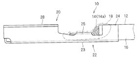
- FIG. 1 is a schematic side view showing the terminal 20 and the electric wire 12 before crimping
- FIG. 2 is a schematic side view showing the electric wire 10 with terminal.
- the electric wire 12 is configured such that the outer periphery of the core wire portion 14 is covered with a covering portion 16 by extrusion coating or the like.
- the core wire portion 14 is constituted by a stranded wire or a single wire of metal wires such as copper, copper alloy, aluminum, and aluminum alloy. Further, the covering portion 16 at the end of the electric wire 12 is peeled off, and the core wire portion 14 is exposed at the end of the electric wire 12.
- the core wire portion 14 exposed at the end of the electric wire 12 may be referred to as an exposed core wire portion 14a.
- the terminal 20 has a crimping part 22 and a mating connection part 28.
- the counterpart connection portion 28 is a portion connected to the counterpart terminal, and is here formed in a substantially cylindrical shape, so-called female terminal shape. And the other party terminal (what is called a male terminal) which has a pin-shaped or tab-shaped connection part is inserted and connected to this other party connection part 28.
- the mating connection portion 28 may be formed in a pin-shaped or tab-shaped shape, a so-called male terminal shape, and is formed in an annular shape that can be connected to the mating member by a screw or the like. Also good.
- the crimping part 22 is configured to be crimped to the exposed core part 14 a of the electric wire 12.
- the crimping part 22 has a bottom plate part 23, a pair of coated crimping pieces 24, and a pair of core wire crimping pieces 25.
- the bottom plate portion 23 is formed in a long plate shape extending from the proximal end portion side of the counterpart connection portion 28.
- the pair of coated crimping pieces 24 are formed in a long piece shape extending from both side portions of the end portion of the bottom plate portion 23.
- a portion of the crimping portion 22 where the pair of coated crimping pieces 24 is formed is formed in a substantially U-shaped cross section.
- the pair of core wire crimping pieces 25 are formed in a long piece shape extending from both side portions of the bottom plate portion 23 between the pair of coated crimping pieces 24 and the mating connection portion 28. Gaps are provided between the pair of core crimping pieces 25 and the pair of coated crimping pieces 24 and between the pair of coated crimping pieces 24 and the mating connection portion 28. Moreover, the part in which a pair of core wire crimping piece 25 was formed among the crimping
- the pair of core crimping pieces 25 are crimped to the exposed core wire portion 14a so as to hold the exposed core wire portion 14a, and the pair of coated crimping pieces 24 hold the end portions of the covering portion 16.
- the end portion of the electric wire 12 and the terminal 20 are crimped and connected.
- the terminal 20 includes a pair of coated crimping pieces 24, and a configuration in which the terminal 20 is crimped to the coated portion 16 of the electric wire 12 is not essential.
- a coating 18 is formed on the surface of the crimp connection portion between the exposed core portion 14a and the crimp portion 22.
- the coating 18 covers the surface of the connection portion between the exposed core portion 14a and the crimping portion 22, thereby suppressing the adhesion of the liquid to the portion and thereby suppressing the deterioration.
- the potential difference between the two becomes large. For this reason, when moisture adheres to the connection portion between the crimping portion 22 and the exposed core portion 14a, the moisture acts as an electrolysis solution, and there is a possibility that electrolytic corrosion occurs.
- Such a coating 18 can be formed by various methods, for example, by applying a coating material such as a resin by melting it with heat, followed by cooling and solidification.
- the thickness of the coating 18 may be reduced at the projected portion.
- the exposed core wire portion 14 a extends to the mating connection portion 28 due to the compressive force at the time of crimping.
- tip part of the extended exposed core wire part 14a may protrude in the direction away from the baseplate part 23 in the space between a pair of core wire crimping piece 25 and the other party connection part 28.
- the thickness of the coating film 18 tends to be thin at the protruding edge portion of the exposed core portion 14a.
- the core wire crimping piece 25 tends to be compressed with a greater force, and the tip portion of the exposed core wire portion 14 a tends to extend greatly.
- the following method for manufacturing a terminal-attached electric wire and a terminal crimping apparatus are employed.
- FIG. 3 is an explanatory view showing the terminal crimping device 30
- FIG. 4 is a side view showing the core wire upper die 50 of the terminal crimping device 30
- FIG. 5 is a front view showing the core wire upper die 50. It is.
- the terminal crimping device 30 includes a core wire lower mold 40, a core wire upper mold 50, and a pressing member 70.
- the core wire lower mold 40 is fixed to the base 48 so as to protrude upward.
- a lower crimping surface 42 having a cross-sectional arc-shaped groove shape on which a portion of the crimping portion 22 where the pair of core wire crimping pieces 25 are formed can be placed.
- the bottom plate portion 23 of the crimping portion 22 can be placed and supported on the lower die 40 for the core wire with the end portion of the electric wire 12 including the exposed core wire portion 14a disposed in the crimping portion 22. It has become.
- the core wire lower mold 40 is also called an anvil.
- the core wire upper mold 50 is disposed to face the core wire lower mold 40.
- the upper core wire mold 50 is disposed so as to be movable toward and away from the lower core wire mold 40 above the lower core wire mold 40 by an actuator 58 such as an air cylinder or a hydraulic cylinder. ing.
- the crimping portion 22 is disposed on the core wire lower mold 40, and the core wire upper mold 50 is disposed in the crimp portion 22 with the exposed core wire portion 14 a of the electric wire 12 disposed therein. By moving closer to 40, the pair of core wire crimping pieces 25 of the crimping portion 22 is sandwiched between the core wire lower mold 40 and the core wire upper mold 50.
- the core wire upper mold 50 is also called a crimper.
- the holding member 70 is disposed so as to be able to move closer to and away from the lower die 40 for core wire in synchronization with the upper die 50 for core wire (that is, to be able to reciprocate in the approaching direction and away from it). . Then, by moving toward the lower die 40 for core wire, the portion of the exposed core wire portion 14a that protrudes from the pair of core wire crimping pieces 25, that is, the tip edge portion of the exposed core wire portion 14a is pressed toward the terminal 20. It is like that.
- the base end side of the terminal 20 to be crimped corresponds to the pair of coated crimping pieces 24 of the terminal 20 for coating.
- a lower mold 60 and a covering upper mold 62 are disposed.
- the coating lower mold 60 is mounted on the base 48, and the coating upper mold 62 is synchronized with the coating upper mold 50 by the actuator 58 with respect to the coating lower mold 60. It is provided so as to be able to move closer and away.
- the covering upper mold 62 also approaches the covering lower mold 60.
- the pair of coated crimping pieces 24 are moved and deformed inward to crimp the crimped portion 22 to the coated portion 16 of the electric wire 12.
- the core wire upper mold 50 and the pressing member 70 will be described more specifically.
- the upper die 50 for core wire is formed in an elongated plate shape.
- An upper crimping surface 52 extending in a notch groove shape from the distal end portion to the proximal end portion of the core wire upper mold 50 is formed.
- the upper crimping surface 52 is opposed to the lower crimping surface 42.
- the innermost (upper) portion of the upper pressure-bonding surface 52 is formed in a shape in which two arc-shaped peripheral surfaces that protrude upward are arranged side by side, and both side surfaces on the front end side of the upper pressure-bonding surface 52 are directed toward the front end side. It is formed in a shape that expands sequentially.
- the upper crimping surface 52 has substantially the same cross-sectional shape along the longitudinal direction of the exposed core wire portion 14a to be disposed between the core wire lower mold 40 and the core wire upper mold 50. Then, when the upper core wire mold 50 is moved toward the lower core wire mold 40 in a state where the crimp portion 22 is placed and supported on the lower core wire mold 40, the pair of core wire crimping pieces 25 is formed. While being in sliding contact with the upper pressure-bonding surface 52, it is curved and deformed inward along the upper pressure-bonding surface 52.
- the pressing member 70 is disposed at a position above the gap between the pair of core wire crimping pieces 25 of the terminal 20 disposed on the core wire lower mold 40 and the mating connection portion 28.
- the holding member 70 is integrally formed on the surface opposite to the covering upper mold 62 with respect to the core upper mold 50. That is, the upper part of the upper core wire mold 50 is formed thicker than the lower part thereof, and extends downward from the center in the width direction of the lower end portion of the thick part 71 so as to extend upward.
- a pressing member 70 is formed to protrude from one main surface of the protrusion 50 into a protrusion.
- the width dimension of the pressing member 70 is formed to be approximately the same as the width of the lower pressure-bonding surface 42, but may be formed to a larger width.
- the front end surface of the pressing member 70 is formed on a pressing surface 72 orthogonal to the approaching / separating movement direction of the pressing member 70.
- the pressing member 70 is moved toward and away from the terminal 20 in synchronism with and integrally with the core wire upper mold 50.
- the pressing surface 72 is formed at the same position as the innermost position of the upper pressure-bonding surface 52 in the approaching / separating movement direction.
- the presser surface 72 when the upper crimping surface 52 crimps the pair of core wire crimping pieces 25, the presser surface 72 is within the range in which the presser surface 72 can press the leading edge of the exposed core wire portion 14 a, and the presser surface 72 has the upper crimping surface 52. It may be shifted upward or downward from the position of the innermost part.
- the pressing member 70 is integrally formed with the core wire upper mold 50.
- the core wire upper mold 150 and the pressing member 170 may be separated.
- the thick portion 71 and the portion corresponding to the pressing member 70 are integrally formed.
- positioning holes 150h and 160h are formed in the core wire upper mold 150 and the pressing member 170, respectively.
- the upper die 150 for core wires and the pressing member 170 are piled up closely.
- the positioning pin 168 is inserted into the positioning holes 150h and 160h, so that the core wire upper mold 150 and the holding member 170 are integrated, and both are synchronized and the core wire upper portion is synchronized.
- the terminal 20 on the mold 50 moves toward and away from the terminal 20.
- the upper die 150 for core wires and the pressing member 170 are separated, it is not essential that the two are in close contact.
- the core wire upper mold 150 and the pressing member 170 are connected to the same actuator 58 and are provided so as to be able to move toward and away from each other synchronously, there may be a gap between the respective tip portions.
- the core wire upper mold 150 and the presser member 170 are closely stacked, the core wire upper mold 150 and the presser member 170 are less likely to be deformed, and there is dust or the like between them. There is a merit in that it is difficult to be caught.
- the terminal 20 and the electric wire 12 shown in FIG. 1 are prepared. Then, as shown in FIG. 3, the crimping portion 22 of the terminal 20 with the core wire upper mold 50 and the coating upper mold 62 being separated from the core wire lower mold 40 and the coating lower mold 60. Is placed on the lower die 40 for core wire and the lower die 60 for covering. Then, the exposed core part 14 a is disposed in the crimping part 22. At this time, the pair of core wire crimping pieces 25 of the bottom plate portion 23 of the crimping portion 22 are disposed on the core wire lower mold 40 and the pair of coated crimping pieces 24 of the bottom plate portion 23 are covered with the covering lower metal. It is disposed on the mold 60. In addition, the exposed core wire portion 14a of the electric wire 12 is disposed in the pair of core wire crimping piece 25 portions, and the end portion of the covering portion 16 is disposed in the pair of coated crimping piece 24 portions.
- the core wire upper mold 50 and the coating upper mold 62 are moved close to the core wire lower mold 40 and the coating lower mold 60.
- the portion of the crimping portion 22 provided with the pair of core wire crimping pieces 25 is sandwiched between the core wire lower die 40 and the core wire upper die 50 so that the pair of core wire crimping pieces 25 are
- the pair of coated crimping pieces 24 are also deformed inward and crimped to the end of the covering portion 16 (see FIGS. 9 and 10).
- the compressed exposed core wire portion 14 a protrudes from the pair of core wire crimping pieces 25 toward the mating connection portion 28, and the leading edge thereof tends to protrude upward.
- the exposed edge portion of the exposed core portion 14 a is pressed toward the terminal 20 by the pressing member 70. Thereby, the front-end
- a coating material is applied to the surface of the crimp connection portion between the exposed core portion 14 a and the crimp portion 22 to form the coating 18.
- the crimping part 22 is sandwiched between the core wire lower mold 40 and the core wire upper mold 50, and the crimping part 22.
- the portion of the exposed core portion 14a that protrudes from the crimp portion 22 is pressed into the terminal 20, so that the protrusion of the exposed core portion 14a from the terminal 20 can be made as small as possible. it can.
- compression-bonding part 22 can be made as small as possible, and it can suppress that the coating film 18 becomes thin partially.
- the tip edge portion of the exposed core wire portion 14a is pressed when the core wire crimping piece 25 is crimped, the pressing operation can be easily performed.
- the press member 70 formed integrally with the core wire upper mold 50 by performing the pressing operation of the tip edge portion of the exposed core wire portion 14a by the press member 70 formed integrally with the core wire upper mold 50, the deformation of the press member 70 is suppressed and the durability is improved. Can do. Moreover, it can suppress that dust etc. adhere between the upper metal mold
- the press member 170 by performing the pressing operation of the tip edge portion of the exposed core wire portion 14a by the press member 170 separate from the core wire upper mold 150, for example, a press member for the existing core wire upper mold 50 is provided.
- the additional installation of 170, the replacement of the core wire upper mold 150 or the pressing member 170 alone, and the like can be easily performed.
Abstract
電線の端部の露出芯線部に端子の圧着部が圧着された端子付電線の製造方法であって、(a)前記圧着部内に前記露出芯線部を配設する工程と、(b)下金型と上金型との間で前記圧着部を挟んで、前記圧着部を前記露出芯線部に圧着する工程とを備える。端子付電線の製造方法は、(c)前記工程(b)において、前記露出芯線部のうち前記圧着部からはみ出る部分を前記端子に向けて押える工程をさらに備える。
Description
この発明は、電線端部の露出芯線部に端子を圧着する技術に関する。
従来、端子付電線として特許文献2に開示のものがある。特許文献2では、端子に芯線圧着用バレルが設けられ、この芯線圧着用バレルが電線端末から露出する芯線にかしめ圧着されている。
特許文献1には、鋼板に塗布される保護被膜の例が開示されている。
しかしながら、電線の端部に露出する芯線に端子をかしめ圧着すると、圧縮力によって芯線部が伸びてしまい、大きく突出してしまう。このような端子と電線との接続部分の表面に、上記被膜形成用の保護剤を塗布すると、芯線部が大きく突出した部分で先端縁部の膜厚が薄くなってしまい、十分な保護性能が得られない恐れがある。
そこで、本発明は、電線の端部の露出芯線部に端子を圧着する際に、端子からの露出芯線部の突出をなるべく小さくすることを目的とする。
上記課題を解決するため、第1の態様は、電線の端部の露出芯線部に端子の圧着部が圧着された端子付電線の製造方法であって、(a)前記圧着部内に前記露出芯線部を配設する工程と、(b)下金型と上金型との間で前記圧着部を挟んで、前記圧着部を前記露出芯線部に圧着する工程と、(c)前記工程(b)において、前記露出芯線部のうち前記圧着部からはみ出る部分を前記端子に向けて押える工程とを備える。
第2の態様は、第1の態様に係る端子付電線の製造方法であって、前記工程(c)では、前記上金型と一体形成された押え部材によって、前記露出芯線部のうち前記圧着部からはみ出る部分を前記端子に向けて押えるようにしている。
第3の態様は、第1の態様に係る端子付電線の製造方法であって、前記工程(c)では、前記上金型と別体とされ、かつ、前記上金型と同期して移動する押え部材によって、前記露出芯線部のうち前記圧着部からはみ出る部分を前記端子に向けて押えるようにしている。
また、上記課題を解決するため、第4の態様は、電線の端部の露出芯線部に端子の圧着部を圧着する端子圧着装置であって、内部に前記露出芯線部が配設された前記圧着部を配設可能な下金型と、前記下金型に対して接近離隔移動可能に配設され、前記下金型に向けて移動することで、前記下金型との間で前記圧着部を挟んで、前記圧着部を前記露出芯線部に圧着する上金型と、前記上金型と同期して移動可能に配設され、前記下金型に向けて移動することで、前記露出芯線部のうち前記圧着部からはみ出る部分を前記端子に向けて押える押え部材とを備える。
第1の態様によると、下金型と上金型との間で前記圧着部を挟んで、前記圧着部を前記露出芯線部に圧着する際に、前記露出芯線部のうち前記圧着部からはみ出る部分を前記端子に向けて押えるため、端子からの露出芯線部の突出をなるべく小さくすることができる。
第2の態様によると、上金型と押え部材とが一体化されているため、押え部材の耐久性が向上する。
第3の態様によると、上金型に対する押え部材の追加、交換等を容易に行える。
第4の態様によると、下金型と上金型との間で前記圧着部を挟んで前記圧着部を前記露出芯線部に圧着する際に、前記露出芯線部のうち前記圧着部からはみ出る部分を前記端子に向けて押えることができるため、端子からの露出芯線部の突出をなるべく小さくすることができる。
以下、実施形態に係る端子付電線の製造方法及び端子圧着装置について説明する。
まず、端子付電線10について説明する。図1は圧着前の端子20及び電線12を示す概略側面図であり、図2は端子付電線10を示す概略側面図である。
電線12は、芯線部14の外周に被覆部16が押出被覆等によって被覆された構成とされている。芯線部14は、銅、銅合金、アルミニウム、アルミニウム合金等の金属線の撚り合せ線又は単線によって構成されている。また、電線12の端部の被覆部16が皮剥ぎされ、電線12の端部に芯線部14が露出している。以下、電線12の端部に露出する芯線部14を露出芯線部14aと表記する場合がある。
端子20は、圧着部22と相手側接続部28とを有している。
相手側接続部28は、相手側の端子と接続される部分であり、ここでは、略筒状の形状、いわゆるメス端子形状に形成されている。そして、この相手側接続部28に、ピン状又はタブ状の接続部を有する相手側端子(いわゆるオス端子)が挿入接続される。もっとも、相手側接続部28は、ピン状又はタブ状の形状、いわゆるオス端子形状に形成されていてもよく、また、ネジ等によって相手側の部材に接続可能な環状形状等に形成されていてもよい。
圧着部22は、電線12の露出芯線部14aに圧着接続可能に構成されている。ここでは、圧着部22は、底板部23と、一対の被覆圧着片24と、一対の芯線圧着片25とを有している。底板部23は、相手側接続部28の基端部側より延出する長尺板状に形成されている。一対の被覆圧着片24は、底板部23の端部の両側部より延出する長尺片状に形成されている。圧着部22のうちこの一対の被覆圧着片24が形成された部分は、断面略U字状に形成されている。一対の芯線圧着片25は、一対の被覆圧着片24と相手側接続部28との間で、底板部23の両側部より延出する長尺片状に形成されている。この一対の芯線圧着片25と一対の被覆圧着片24との間、及び、一対の被覆圧着片24と相手側接続部28との間には隙間が設けられている。また、圧着部22のうち一対の芯線圧着片25が形成された部分は、断面略U字状に形成されている。
そして、上記一対の芯線圧着片25が露出芯線部14aを抱持するように当該露出芯線部14aに圧着されると共に、一対の被覆圧着片24が被覆部16の端部を抱持するように当該被覆部16に圧着されることにより、電線12の端部と端子20とが圧着接続される。
なお、端子20が一対の被覆圧着片24を備えており、電線12の被覆部16に圧着される構成は必須ではない。
また、露出芯線部14aと圧着部22との圧着接続部分の表面には、被膜18が形成されている。被膜18は、露出芯線部14aと圧着部22との接続部分表面を覆うことで、当該部分への液体の付着等を抑制し、もって劣化を抑制する役割を果す。特に、芯線部14としてアルミニウム又はアルミニウム合金を用い、端子20として銅又は銅合金の表面にスズメッキ層が形成された構成のものを用いた場合、両者間で電位差が大きくなる。このため、圧着部22と露出芯線部14aとの接続部分に水分が付着すると、水分が電界液として作用し、電食が生じてしまう恐れがある。そこで、上記のように、露出芯線部14aと圧着部22との圧着接続部分の表面に被膜18を形成することで、その表面部分での電食を有効に抑制することができる。このような被膜18は、例えば、樹脂等の塗布材料を熱で溶融させて塗布した後、冷却固化する等、各種方法にて形成することができる。
露出芯線部14aと圧着部22との圧着接続部分の表面に塗布材料を塗布する際、塗布対象箇所が部分的に突出していると、その突出した部分で被膜18の厚みが薄くなってしまう恐れがある。例えば、露出芯線部14aに一対の芯線圧着片25を圧着する際、圧着の際の圧縮力によって露出芯線部14aが相手側接続部28に伸びてしまう。そして、伸びた露出芯線部14aの先端部が、一対の芯線圧着片25と相手側接続部28との間の空間で底板部23から離れる方向に突出してしまう恐れがある。すると、露出芯線部14aのうち突出した先端縁部で被膜18の厚みが薄くなりやすい。特に、芯線部14としてアルミニウム線又はアルミニウム合金線を用いた場合、芯線圧着片25はより大きな力で圧縮される傾向にあり、露出芯線部14aの先端部が大きく伸び出やすい。
かかる問題を解決するため、本実施形態では、下記の端子付電線の製造方法及び端子圧着装置を採用している。
端子圧着装置30について説明する。図3は端子圧着装置30を示す説明図であり、図4は同端子圧着装置30の芯線用上金型50を示す側面図であり、図5は同芯線用上金型50を示す正面図である。
この端子圧着装置30は、芯線用下金型40と芯線用上金型50と押え部材70とを備えている。
芯線用下金型40は、基台48に上方に向けて突出するように固定されている。芯線用下金型40の上面には、圧着部22のうち一対の芯線圧着片25が形成された部分を載置可能な断面弧状溝形状の下側圧着面42が形成されている。そして、圧着部22内に露出芯線部14aを含む電線12の端部を配設した状態で、圧着部22の底板部23を、芯線用下金型40上に載置して支持できるようになっている。この芯線用下金型40は、アンビルとも呼ばれる。
芯線用上金型50は、上記芯線用下金型40に対向して配設されている。ここで、芯線用上金型50は、エアシリンダや油圧シリンダ等のアクチュエータ58により、芯線用下金型40の上方で、当該芯線用下金型40に対して接近離隔移動可能に配設されている。そして、芯線用下金型40上に圧着部22を配設すると共に、圧着部22内に電線12の露出芯線部14aを配設した状態で、芯線用上金型50を芯線用下金型40に向けて接近移動させることで、芯線用下金型40と芯線用上金型50との間で圧着部22のうち一対の芯線圧着片25部分が挟込まれる。これにより、一対の芯線圧着片25が露出芯線部14a上に覆い被さるように変形して、圧着部22が露出芯線部14aに圧着される。かかる芯線用上金型50は、クリンパとも呼ばれる。
押え部材70は、上記芯線用上金型50と同期して芯線用下金型40に対して接近離隔移動可能に(つまり、接近する方向及び遠ざかる方向に往復移動可能に)配設されている。そして、芯線用下金型40に向けて接近移動することで、露出芯線部14aのうち一対の芯線圧着片25からはみ出る部分、つまり、露出芯線部14aの先端縁部を端子20に向けて押えるようになっている。
なお、上記芯線用下金型40及び芯線用上金型50に対して、圧着対象となる端子20の基端側には、当該端子20の一対の被覆圧着片24に対応して、被覆用下金型60及び被覆用上金型62が配設されている。被覆用下金型60は基台48上に取付けられており、被覆用上金型62は、アクチュエータ58により、上記芯線用上金型50と同期して、被覆用下金型60に対して接近離隔移動可能に設けられている。そして、上記芯線用下金型40と芯線用上金型50との間で圧着部22を露出芯線部14aに圧着する際、被覆用上金型62も被覆用下金型60に対して接近移動して、一対の被覆圧着片24を内側に変形させて当該圧着部22を電線12の被覆部16に圧着させるようになっている。
芯線用上金型50及び押え部材70についてより具体的に説明する。
芯線用上金型50は、細長板状に形成されている。芯線用上金型50の先端部から基端部に向けて切欠溝状に延びる上側圧着面52が形成されている。この上側圧着面52は、上記下側圧着面42と対向している。上側圧着面52の最奥(上)部は、上向きに凸となる弧状周面を2つ横並びにした形状に形成されており、上側圧着面52の先端側両側面は、先端側に向けて順次拡開する形状に形成されている。この上側圧着面52は、芯線用下金型40と芯線用上金型50との間に配設されることとなる露出芯線部14aの長手方向に沿って略同一断面形状とされている。そして、芯線用下金型40上に圧着部22を載置支持した状態で、本芯線用上金型50を芯線用下金型40に向けて接近移動させると、一対の芯線圧着片25が上記上側圧着面52に摺接しつつ当該上側圧着面52に沿って内向きに湾曲変形するようになっている。
押え部材70は、芯線用下金型40上に配設される端子20の一対の芯線圧着片25と相手側接続部28との間の隙間の上方位置に配設されている。
より具体的には、押え部材70は、芯線用上金型50に対して被覆用上金型62の反対側の面に一体形成されている。すなわち、芯線用上金型50の上部は、その下部よりも肉厚に形成されており、その肉厚部分71の下端部の幅方向中央部より下方に延びるようにして、芯線用上金型50の一主面より突条に突出する押え部材70が形成されている。ここでは、押え部材70の幅寸法は、下側圧着面42の幅とほぼ同じ程度の幅に形成されているが、より大きな幅に形成されていてもよい。また、押え部材70の先端面は、押え部材70の接近離隔移動方向に対して直交する押え面72に形成されている。これにより、押え部材70が芯線用上金型50と同期しかつ一体となって、端子20に向けて接近離隔移動するようになっている。ここでは、押え面72は、その接近離隔移動方向において、上側圧着面52の最奥部の位置と同じ位置に形成されている。そして、上側圧着面52が一対の芯線圧着片25を圧着する際に、押え面72が露出芯線部14aのうち一対の芯線圧着片25より突出する先端縁部に当接するようになっている。もっとも、上側圧着面52が一対の芯線圧着片25を圧着する際に、押え面72が露出芯線部14aの先端縁部を押え付けることが可能な範囲で、押え面72が、上側圧着面52の最奥部の位置よりも上方又は下方にずれていてもよい。
なお、押え部材70が芯線用上金型50と一体形成されていることは必須ではない。図6~図8に示すように、芯線用上金型150と、押え部材170とが別体とされていてもよい。ここでは、押え部材170は、上記肉厚部分71と押え部材70に対応する部分とが一体形成されている。また、芯線用上金型150と押え部材170とにそれぞれ位置決用孔150h、160hが形成されている。そして、芯線用上金型150と押え部材170とが密接状態に重ね合されている。また、この重ね合せ状態で、位置決めピン168が位置決用孔150h、160hに挿通されることで、芯線用上金型150と押え部材170とが一体化され、両者が同期して芯線用上金型50上の端子20に対して接近離隔移動するようになっている。
なお、芯線用上金型150と押え部材170とを別体とした場合、両者が密接していることは必須ではない。例えば、芯線用上金型150と押え部材170とが同じアクチュエータ58に連結され、同期して接近離隔移動可能に設けられていれば、それぞれの先端部間に隙間があってもよい。もっとも、芯線用上金型150と押え部材170とが密接状態に重ね合されている方が、芯線用上金型150と押え部材170とが変形しにくくなり、また、両者間にゴミ等が挟込まれ難いという点でメリットがある。
この端子圧着装置30を用いた端子付電線10の製造方法について説明する。
まず、図1に示す端子20及び電線12を準備する。そして、図3に示すように、芯線用上金型50及び被覆用上金型62を、芯線用下金型40及び被覆用下金型60から離間させた状態で、端子20の圧着部22を芯線用下金型40及び被覆用下金型60上に載置する。そして、圧着部22内に露出芯線部14aを配設する。この際、圧着部22の底板部23のうち一対の芯線圧着片25部分を芯線用下金型40上に配設すると共に、底板部23のうち一対の被覆圧着片24部分を被覆用下金型60上に配設する。また、電線12の露出芯線部14aを一対の芯線圧着片25部分に配設すると共に、被覆部16の端部を一対の被覆圧着片24部分に配設する。
そして、芯線用上金型50及び被覆用上金型62を、芯線用下金型40及び被覆用下金型60に接近移動させる。これにより、芯線用下金型40と芯線用上金型50との間で、圧着部22のうち一対の芯線圧着片25が設けられた部分を挟込んで、一対の芯線圧着片25をうち向けに変形させて露出芯線部14aに圧着すると共に、一対の被覆圧着片24もうち向けに変形させて被覆部16の端部に圧着する(図9及び図10参照)。この際、圧縮された露出芯線部14aが一対の芯線圧着片25から相手側接続部28側にはみ出て、その先端縁部が上方に突出しようとする。この露出芯線部14aの先端縁部を、押え部材70により端子20に向けて押え込む。これにより、露出芯線部14aの先端縁部が端子20内に向けて押え込まれ、その突出が抑制される。
この後、露出芯線部14aと圧着部22との圧着接続部分の表面に、塗布材料を塗布して、被膜18を形成する。
以上のように構成された端子付電線10の製造方法及び端子圧着装置30によると、芯線用下金型40と芯線用上金型50との間で圧着部22を挟込んで、圧着部22を露出芯線部14aに圧着する際に、露出芯線部14aのうち圧着部22からはみ出る部分を端子20内に向けて押え付ける為、端子20からの露出芯線部14aの突出をなるべく小さくすることができる。これにより、露出芯線部14aと圧着部22との圧着接続部分の表面の凹凸をなるべく小さくし、被膜18が部分的に薄くなることを抑制できる。
しかも、芯線圧着片25を圧着する際に、露出芯線部14aの先端縁部を押え付けているため、当該押え付け作業も容易に行える。
また、露出芯線部14aの先端縁部の押え付け作業を、芯線用上金型50と一体形成された押え部材70によって行うことによって、押え部材70の変形を抑制して耐久性を向上させることができる。また、芯線用上金型50と押え部材70との間にゴミ等が付着することを抑制でき、メンテナンス性に優れる。
また、露出芯線部14aの先端縁部の押え付け作業を、芯線用上金型150とは別体とされた押え部材170によって行うことによって、例えば、既存の芯線用上金型50に対する押え部材170の追加設置、芯線用上金型150或は押え部材170単独の交換等を容易に行うことができる。
以上のようにこの発明は詳細に説明されたが、上記した説明は、すべての局面において、例示であって、この発明がそれに限定されるものではない。例示されていない無数の変形例が、この発明の範囲から外れることなく想定され得るものと解される。
Claims (4)
- 電線の端部の露出芯線部に端子の圧着部が圧着された端子付電線の製造方法であって、
(a)前記圧着部内に前記露出芯線部を配設する工程と、
(b)下金型と上金型との間で前記圧着部を挟んで、前記圧着部を前記露出芯線部に圧着する工程と、
(c)前記工程(b)において、前記露出芯線部のうち前記圧着部からはみ出る部分を前記端子に向けて押える工程と、
を備える端子付電線の製造方法。 - 請求項1記載の端子付電線の製造方法であって、
前記工程(c)では、前記上金型と一体形成された押え部材によって、前記露出芯線部のうち前記圧着部からはみ出る部分を前記端子に向けて押える、端子付電線の製造方法。 - 請求項1記載の端子付電線の製造方法であって、
前記工程(c)では、前記上金型と別体とされ、かつ、前記上金型と同期して移動する押え部材によって、前記露出芯線部のうち前記圧着部からはみ出る部分を前記端子に向けて押える、端子付電線の製造方法。 - 電線の端部の露出芯線部に端子の圧着部を圧着する端子圧着装置であって、
内部に前記露出芯線部が配設された前記圧着部を配設可能な下金型と、
前記下金型に対して接近離隔移動可能に配設され、前記下金型に向けて移動することで、前記下金型との間で前記圧着部を挟んで、前記圧着部を前記露出芯線部に圧着する上金型と、
前記上金型と同期して移動可能に配設され、前記下金型に向けて移動することで、前記露出芯線部のうち前記圧着部からはみ出る部分を前記端子に向けて押える押え部材と、
を備える端子圧着装置。
Applications Claiming Priority (2)
| Application Number | Priority Date | Filing Date | Title |
|---|---|---|---|
| JP2011063606A JP2012199168A (ja) | 2011-03-23 | 2011-03-23 | 端子付電線の製造方法及び端子圧着装置 |
| JP2011-063606 | 2011-03-23 |
Publications (1)
| Publication Number | Publication Date |
|---|---|
| WO2012127890A1 true WO2012127890A1 (ja) | 2012-09-27 |
Family
ID=46879060
Family Applications (1)
| Application Number | Title | Priority Date | Filing Date |
|---|---|---|---|
| PCT/JP2012/050790 WO2012127890A1 (ja) | 2011-03-23 | 2012-01-17 | 端子付電線の製造方法及び端子圧着装置 |
Country Status (2)
| Country | Link |
|---|---|
| JP (1) | JP2012199168A (ja) |
| WO (1) | WO2012127890A1 (ja) |
Families Citing this family (1)
| Publication number | Priority date | Publication date | Assignee | Title |
|---|---|---|---|---|
| JP6404295B2 (ja) * | 2016-10-13 | 2018-10-10 | 矢崎総業株式会社 | 端子圧着装置 |
Citations (4)
| Publication number | Priority date | Publication date | Assignee | Title |
|---|---|---|---|---|
| JPH0714658A (ja) * | 1993-06-22 | 1995-01-17 | Sumitomo Wiring Syst Ltd | 端子圧着装置及び端子圧着方法 |
| JPH0750191A (ja) * | 1993-08-04 | 1995-02-21 | Sumitomo Wiring Syst Ltd | 端子圧着装置 |
| JPH11219769A (ja) * | 1998-02-03 | 1999-08-10 | Yazaki Corp | 端子及びそれを形成するための金型 |
| JP2003168536A (ja) * | 2001-12-04 | 2003-06-13 | Yazaki Corp | 端子圧着型およびそれを有する端子圧着機 |
Family Cites Families (1)
| Publication number | Priority date | Publication date | Assignee | Title |
|---|---|---|---|---|
| JPS5027594B1 (ja) * | 1970-04-11 | 1975-09-09 |
-
2011
- 2011-03-23 JP JP2011063606A patent/JP2012199168A/ja not_active Abandoned
-
2012
- 2012-01-17 WO PCT/JP2012/050790 patent/WO2012127890A1/ja active Application Filing
Patent Citations (4)
| Publication number | Priority date | Publication date | Assignee | Title |
|---|---|---|---|---|
| JPH0714658A (ja) * | 1993-06-22 | 1995-01-17 | Sumitomo Wiring Syst Ltd | 端子圧着装置及び端子圧着方法 |
| JPH0750191A (ja) * | 1993-08-04 | 1995-02-21 | Sumitomo Wiring Syst Ltd | 端子圧着装置 |
| JPH11219769A (ja) * | 1998-02-03 | 1999-08-10 | Yazaki Corp | 端子及びそれを形成するための金型 |
| JP2003168536A (ja) * | 2001-12-04 | 2003-06-13 | Yazaki Corp | 端子圧着型およびそれを有する端子圧着機 |
Also Published As
| Publication number | Publication date |
|---|---|
| JP2012199168A (ja) | 2012-10-18 |
Similar Documents
| Publication | Publication Date | Title |
|---|---|---|
| JP5720527B2 (ja) | 端子付電線の製造方法、および、端子圧着装置 | |
| US20110094797A1 (en) | Electric wire with terminal connector and method of manufacturing electric wire with terminal connector | |
| US9065189B2 (en) | Water proof crimping terminal and crimping method of water proof crimping terminal | |
| US20150364835A1 (en) | Method of manufacturing connection structural body, connection structural body, wire harness, crimping member and crimping device | |
| WO2014097672A1 (ja) | 端子付電線の製造方法、および、端子付電線 | |
| JP4983467B2 (ja) | 端子圧着装置、端子圧着電線の製造方法及び端子圧着電線 | |
| WO2019039379A1 (ja) | 端子付電線の製造方法、端子付電線及び超音波接合装置 | |
| WO2017068963A1 (ja) | 端子付き電線の製造方法、圧着冶具、および端子付き電線 | |
| WO2013057970A1 (ja) | 端子付き電線、端子付き電線の製造方法および端子圧着装置 | |
| WO2017068974A1 (ja) | 端子用金属板、端子及び端子対 | |
| JP2017033776A (ja) | 圧着端子及びその製造方法並びに電線、ワイヤハーネス | |
| JP2010055937A (ja) | 端子金具及び端子金具付き電線 | |
| WO2021010148A1 (ja) | 端子、および端子付き電線 | |
| WO2012127890A1 (ja) | 端子付電線の製造方法及び端子圧着装置 | |
| JP2009037908A (ja) | 端子圧着装置、端子圧着電線の製造方法及び端子圧着電線 | |
| US11637386B2 (en) | Terminal and terminal wire assembly | |
| JP2018081818A (ja) | 圧着端子および端子付き電線 | |
| JP6387441B1 (ja) | 端子圧着装置及び端子圧着方法 | |
| JP6614181B2 (ja) | 圧着加工物の製造方法 | |
| JP5720955B2 (ja) | 端子の製造方法および連鎖端子 | |
| JP5011173B2 (ja) | 端子圧着装置、及びワイヤーハーネスの製造方法 | |
| JP5125941B2 (ja) | 端子圧着装置 | |
| JP7442943B2 (ja) | 端子付き電線の製造方法 | |
| US20220069534A1 (en) | Terminal crimping device | |
| JP6324267B2 (ja) | 圧着接続構造体の製造方法 |
Legal Events
| Date | Code | Title | Description |
|---|---|---|---|
| 121 | Ep: the epo has been informed by wipo that ep was designated in this application |
Ref document number: 12761506 Country of ref document: EP Kind code of ref document: A1 |
|
| NENP | Non-entry into the national phase |
Ref country code: DE |
|
| 122 | Ep: pct application non-entry in european phase |
Ref document number: 12761506 Country of ref document: EP Kind code of ref document: A1 |