WO2012127776A1 - 車両用表示装置 - Google Patents
車両用表示装置 Download PDFInfo
- Publication number
- WO2012127776A1 WO2012127776A1 PCT/JP2012/001128 JP2012001128W WO2012127776A1 WO 2012127776 A1 WO2012127776 A1 WO 2012127776A1 JP 2012001128 W JP2012001128 W JP 2012001128W WO 2012127776 A1 WO2012127776 A1 WO 2012127776A1
- Authority
- WO
- WIPO (PCT)
- Prior art keywords
- screen
- specific area
- terminal screen
- enlarged
- display unit
- Prior art date
- Legal status (The legal status is an assumption and is not a legal conclusion. Google has not performed a legal analysis and makes no representation as to the accuracy of the status listed.)
- Ceased
Links
Images



Classifications
-
- G—PHYSICS
- G01—MEASURING; TESTING
- G01C—MEASURING DISTANCES, LEVELS OR BEARINGS; SURVEYING; NAVIGATION; GYROSCOPIC INSTRUMENTS; PHOTOGRAMMETRY OR VIDEOGRAMMETRY
- G01C21/00—Navigation; Navigational instruments not provided for in groups G01C1/00 - G01C19/00
- G01C21/26—Navigation; Navigational instruments not provided for in groups G01C1/00 - G01C19/00 specially adapted for navigation in a road network
- G01C21/34—Route searching; Route guidance
- G01C21/36—Input/output arrangements for on-board computers
- G01C21/3626—Details of the output of route guidance instructions
- G01C21/3632—Guidance using simplified or iconic instructions, e.g. using arrows
-
- G—PHYSICS
- G01—MEASURING; TESTING
- G01C—MEASURING DISTANCES, LEVELS OR BEARINGS; SURVEYING; NAVIGATION; GYROSCOPIC INSTRUMENTS; PHOTOGRAMMETRY OR VIDEOGRAMMETRY
- G01C21/00—Navigation; Navigational instruments not provided for in groups G01C1/00 - G01C19/00
- G01C21/26—Navigation; Navigational instruments not provided for in groups G01C1/00 - G01C19/00 specially adapted for navigation in a road network
- G01C21/34—Route searching; Route guidance
- G01C21/36—Input/output arrangements for on-board computers
- G01C21/3667—Display of a road map
- G01C21/367—Details, e.g. road map scale, orientation, zooming, illumination, level of detail, scrolling of road map or positioning of current position marker
-
- G—PHYSICS
- G01—MEASURING; TESTING
- G01C—MEASURING DISTANCES, LEVELS OR BEARINGS; SURVEYING; NAVIGATION; GYROSCOPIC INSTRUMENTS; PHOTOGRAMMETRY OR VIDEOGRAMMETRY
- G01C21/00—Navigation; Navigational instruments not provided for in groups G01C1/00 - G01C19/00
- G01C21/26—Navigation; Navigational instruments not provided for in groups G01C1/00 - G01C19/00 specially adapted for navigation in a road network
- G01C21/34—Route searching; Route guidance
- G01C21/36—Input/output arrangements for on-board computers
- G01C21/3679—Retrieval, searching and output of POI information, e.g. hotels, restaurants, shops, filling stations, parking facilities
- G01C21/3682—Retrieval, searching and output of POI information, e.g. hotels, restaurants, shops, filling stations, parking facilities output of POI information on a road map
-
- G—PHYSICS
- G09—EDUCATION; CRYPTOGRAPHY; DISPLAY; ADVERTISING; SEALS
- G09B—EDUCATIONAL OR DEMONSTRATION APPLIANCES; APPLIANCES FOR TEACHING, OR COMMUNICATING WITH, THE BLIND, DEAF OR MUTE; MODELS; PLANETARIA; GLOBES; MAPS; DIAGRAMS
- G09B29/00—Maps; Plans; Charts; Diagrams, e.g. route diagram
-
- G—PHYSICS
- G09—EDUCATION; CRYPTOGRAPHY; DISPLAY; ADVERTISING; SEALS
- G09B—EDUCATIONAL OR DEMONSTRATION APPLIANCES; APPLIANCES FOR TEACHING, OR COMMUNICATING WITH, THE BLIND, DEAF OR MUTE; MODELS; PLANETARIA; GLOBES; MAPS; DIAGRAMS
- G09B29/00—Maps; Plans; Charts; Diagrams, e.g. route diagram
- G09B29/10—Map spot or coordinate position indicators; Map reading aids
-
- H—ELECTRICITY
- H04—ELECTRIC COMMUNICATION TECHNIQUE
- H04M—TELEPHONIC COMMUNICATION
- H04M2250/00—Details of telephonic subscriber devices
- H04M2250/16—Details of telephonic subscriber devices including more than one display unit
Definitions
- the present disclosure relates to a vehicle display device.
- Patent Document 1 Description of the Related Art Devices that can display a display screen of an external terminal device are known as vehicle display devices. For example, this is the device of Patent Document 1.
- the device of Patent Document 1 can display a screen of a mobile terminal on a display unit of a vehicle.
- region information (screen size) is acquired from a portable terminal, The screen of a portable terminal is made into the screen of the display part of a vehicle by comparing the area
- examples of a plurality of screens each converted at a plurality of different magnifications are disclosed, such as an example where the screen of the mobile terminal is reduced so that all the screens can enter, or an example where the screen of the mobile terminal is enlarged and displayed. Has been.
- a scroll button is prepared because the screen of the mobile terminal does not fit in the display unit of the vehicle.
- Patent Document 1 the entire screen of the mobile terminal is converted by a certain vertical and horizontal magnification and displayed on the display unit of the vehicle.
- the entire screen of the mobile terminal if the entire screen of the mobile terminal is displayed on the display unit of the vehicle, the entire screen becomes small, and it is difficult to recognize details of the screen in a short time. turn into.
- the entire screen is enlarged, and thus the entire screen of the mobile terminal cannot be displayed on the display unit of the vehicle at a time. Therefore, the entire screen of the mobile terminal cannot be confirmed unless the screen is scrolled.
- the present disclosure has been made based on this circumstance, and the purpose of the present disclosure is to make it easy to confirm necessary portions in a display device for a vehicle that displays a screen of a terminal device, and the screen of the terminal device. It is to make the whole easier to check.
- a vehicle display device connected to a terminal device including a display unit includes a vehicle display unit mounted on a vehicle and a display control device.
- the display control device causes the vehicle display unit to display a pseudo terminal screen representing a terminal screen displayed on the display unit of the terminal device.
- the display control device further enlarges a specific area, which is a part of the terminal screen, from the other areas of the terminal screen and displays the specific area on the vehicle display unit.
- the method for displaying the terminal screen of the display unit of the terminal device on the display unit of the vehicle display device connected to the terminal device including the display unit includes the display unit of the terminal device.
- the entire pseudo terminal screen representing the entire terminal screen is displayed on the display unit of the vehicle display device, and when it is determined that the empty area exists, the entire pseudo terminal screen representing the entire terminal screen is displayed.
- the free area that is displayed on the display unit of the dual-use display device, and the specific area enlarged screen obtained by enlarging the specific area included in the general pseudo terminal screen than the specific area in the general pseudo terminal screen does not overlap the general pseudo terminal screen
- displaying the entire pseudo terminal screen representing the entire terminal screen on the display unit of the vehicle display device, and displaying the specific area included in the entire pseudo terminal screen A specific area enlarged screen enlarged from the other areas on the entire pseudo terminal screen is superimposed on the specific area of the entire pseudo terminal screen and displayed.
- the specific area that is a part of the terminal screen of the terminal device is larger than the other areas, the specific area of the entire pseudo terminal screen displayed on the vehicle display unit is confirmed. It becomes easy to do.
- the pseudo terminal screen can display a wider range of the terminal screen than when the entire terminal screen is enlarged.
- FIG. 1 is a system configuration diagram of a terminal device screen display system 1 to which the present disclosure is applied.
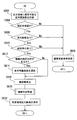
- FIG. 2 is a flowchart showing the control contents executed by the vehicle display device 100.
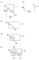
- FIGS. 3A to 3E are diagrams for explaining examples of screens displayed on the display unit 112 in steps S4, S5, and S6 of FIG.
- FIG. 4 is a flowchart showing details of the process in step S6 of FIG. 2 in the second embodiment.
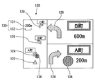
- FIG. 5 is a display example of the display unit 112 when displaying a bent arrow, a landmark, and a place name character in one specific area enlargement screen.
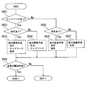
- FIG. 6 is a flowchart showing details of the screen creation processing in step S620 of FIG.
- FIG. 7 is a display example of the display unit 112 when only the bent arrow is handled as an enlarged sign.
- FIG. 1 is a system configuration diagram of a terminal device screen display system 1 including a vehicle display device 100 to which the present disclosure is applied. As shown in FIG. 1, the terminal device screen display system 1 includes a mobile terminal 10 and a vehicle display device 100.
- the mobile terminal 10 corresponds to a terminal device and corresponds to a known smartphone, other mobile phone, PDA, or the like.
- the mobile terminal 10 includes a terminal display unit 11 and also includes a CPU, ROM, RAM, and the like inside (not shown).
- Various application programs are stored in the ROM, and screens having various contents are displayed on the terminal display unit 11 by executing the application programs stored in the ROM by the CPU.
- the screen displayed on the terminal display unit 11 is referred to as a terminal screen.
- Various terminal screens are displayed on the terminal display unit 11 when the type of the mobile terminal 10 is different or the application to be executed is different.
- the specific area to be displayed in an enlarged manner on the display unit 112 of the vehicle display device 100 is displayed with a color and shape set in advance as an enlarged sign.
- region can be determined by analyzing the pixel information input from the portable terminal 10, and recognizing an expansion mark.
- the enlarged sign may be any of color, shape only, color and shape.
- An example of the shape of the enlarged sign is a frame.
- the frame set as the enlarged sign is a frame that is not frequently used in normal drawing. For example, a frame using either a line type or a color that is not frequently used in normal drawing. If the frame is an enlarged sign, the mobile terminal 10 only adds the frame to the graphic set in the existing application, or only changes the frame if the graphic already has the frame. Therefore, it is easy to set an enlarged sign.
- the mobile terminal 10 can communicate with the vehicle display device 100 by at least one of wired communication and wireless communication.
- An example of the wired connection is communication using a USB cable
- an example of the wireless connection is communication based on the Bluetooth (registered trademark) standard.
- the mobile terminal 10 displays pixel information (information indicating the color of each pixel) of each pixel on the terminal screen displayed on the terminal display unit 11. Are sent sequentially.
- an inquiry signal for inquiring whether there is a terminal that can transmit a video signal wirelessly or by wire is transmitted from the vehicle display device 100.
- the vehicle display device 100 further transmits a connection request signal, and communication is established by the mobile terminal 10 returning a connection response.
- a connection request signal for inquiring whether there is a terminal that can transmit a video signal wirelessly or by wire
- the vehicle display device 100 further transmits a connection request signal, and communication is established by the mobile terminal 10 returning a connection response.
- prioritization based on various indexes is performed, and communication is established by limiting the number of mobile terminals 10 to one.
- the index for determining the priority order includes, for example, the order in which the user registers the priority order for the plurality of mobile terminals 10 in advance, in the order of strong radio waves, the order in which the remaining battery power is large, and the like.
- the vehicular display device 100 transmits a signal requesting transmission of the video signal to the mobile terminal 10, thereby transmitting the video signal from the mobile terminal 10 to the vehicular display device 100. Is started.
- the vehicle display device 100 includes a communication unit 102, a control unit 104, a storage unit 106, an image recognition unit 108, an image processing unit 110, a display unit 112, an amplifier 114, and a speaker 116.
- the communication unit 102 communicates with the mobile terminal 10 wirelessly or by wire.
- the communication unit 102 receives a video signal and an audio signal transmitted from the mobile terminal 10. Note that the above-described pixel information is transmitted and received as a video signal.
- the communication unit 102 separates the received video signal and audio signal, the video signal is input to the image recognition unit 108, and the audio signal is input to the amplifier 114.
- the control unit 104 controls the entire vehicle display device 100 and controls the communication unit 102, the image recognition unit 108, the image processing unit 110, and the display unit 112.
- the storage unit 106 stores an enlarged sign list. As an enlarged sign, there is a frame as described above, but there are also a preset character, a preset figure other than the character (for example, an arrow, a facility mark), and the like.
- the enlarged sign is recognized by the color indicated by the pixel information.
- the recognition result and pixel information recognized in this way are input to the image processing unit 110.
- various known image recognition techniques can be used for the image recognition processing. For example, a portion in which the same color continues in the screen may be recognized as one graphic.
- the figure recognized in this way is linear and closed, it is recognized as a figure frame, and the frame and its interior are recognized as one figure. good.
- the color of the recognized figure frame and the inside thereof may be identified.
- a plurality of colors are used for the graphic. In this case, a color whose ratio in the graphic is a predetermined value or more may be recognized.
- the image processing unit 110 corresponds to a display control device.
- the image processing unit 110 creates a pseudo terminal screen using the pixel information input from the image recognition unit 108 and displays the created pseudo terminal screen on the display unit 112.
- the pseudo terminal screen is a screen representing the terminal screen.
- the pseudo terminal screen may not be a screen that accurately reproduces the terminal screen. Due to the difference between the number of vertical and horizontal pixels of the terminal display unit 11 and the number of vertical and horizontal pixels of the display unit 112 of the vehicle display device 100, A screen obtained by enlarging or reducing the entire terminal screen at a constant magnification may be created as a pseudo terminal screen. Moreover, it is good also as a pseudo
- the image processing unit 110 changes the pseudo terminal screen to be created depending on whether or not the display unit 112 has an area for displaying two types of pseudo terminal screens.
- an entire pseudo terminal screen is created by multiplying the entire terminal screen by a certain magnification, and a specific area determined based on the enlarged sign is determined.
- a specific area enlargement screen enlarged at a higher enlargement ratio than the entire pseudo terminal screen is also created. Then, the entire pseudo terminal screen and the specific area enlarged screen are displayed on the display unit 112 so as not to overlap each other.
- the specific area is enlarged with the specific area in the entire pseudo terminal screen overlapped with the above-mentioned entire pseudo terminal screen. Create a pseudo terminal screen with the screen superimposed. Then, the pseudo terminal screen is displayed on the display unit 112.
- the relationship between the enlarged sign and the specific area is determined for each kind of enlarged sign.
- the inside of the frame as an enlarged sign is set as a specific area.
- the enlargement indicator is a character
- only the character or a region including a margin range determined by the character and the size of the character is set as the specific region.
- the degree of enlargement of the specific area may be set in advance, or the size after enlargement may be set in advance. Further, the former or the latter may be different depending on the enlarged sign.
- the aspect ratio may be changed so that the aspect ratio becomes a predetermined ratio while being enlarged.
- the display unit 112 is disposed at a position that is visible to the passenger in the vehicle cabin, and displays the above-described pseudo terminal screen.
- a display provided in a known navigation device can be used as the display unit 112.
- the amplifier 114 amplifies the audio signal input from the communication unit 102 and inputs the amplified audio signal to the speaker 116.
- the speaker 116 converts the input audio signal (electrical signal) into audio and outputs it.
- FIG. 2 is a flowchart showing the control contents executed by the vehicle display device 100. Next, processing of the vehicular display device 100 will be described with reference to FIG. This flowchart is executed in a state where communication between the vehicle display device 100 and the mobile terminal 10 is established and pixel information is sequentially transmitted from the mobile terminal 10.
- step S ⁇ b> 1 the image recognition unit 108 acquires a video signal (pixel information) transmitted from the mobile terminal 10 and received by the communication unit 102 from the communication unit 102. Subsequently, the image recognition unit 108 refers to the enlarged sign list stored in the storage unit 106 and executes image recognition processing for recognizing the enlarged sign from the terminal screen.
- step S3 the image processing unit 110 determines whether or not there is an enlarged sign based on the result of the image recognition processing in step S2. If this determination is “NO”, the process proceeds to step S4, and if “YES”, the process proceeds to step S5.
- step S4 the above-described entire pseudo terminal screen is displayed on the display unit 112.
- step S5 the image processing unit 110 determines whether the display unit 112 has a free area enough to display two pseudo terminal screens. If this determination is “YES”, the process proceeds to step S6, and if “NO”, the process proceeds to step S7.
- step S6 the image processing unit 110 displays the above-described entire pseudo terminal screen and also displays a specific area enlarged screen so as not to overlap the entire pseudo terminal screen.
- step S7 the image processing unit 110 displays a pseudo terminal screen in which the specific area is enlarged at the original place, that is, a screen in which the specific area enlarged screen is superimposed on the entire pseudo terminal screen.
- step S8 the control unit 104 determines whether a new video signal has been input. If this determination is “NO”, step S8 is repeated. On the other hand, if “YES”, the process returns to step S1.
- FIG. 3A is a diagram conceptually showing a terminal screen.
- the terminal screen of FIG. 3 (a) is an enlarged view of a position where a right turn is to be made during route guidance, and a facility graphic 20 indicating a convenience store and a right turn arrow 30 indicating a right turn are shown. ing.
- the terminal screen has 1000 pixels vertically and 500 pixels horizontally.
- FIG. 3B shows the entire display area of the display unit 112 of the vehicular display device 100. As shown in this figure, the display unit 112 has vertical 500 pixels and horizontal 1000 pixels.
- FIG. 3C is an example in which a pseudo terminal screen based on the terminal screen of FIG. 3A is displayed on the display unit 112 of the vehicle display device 100. Due to the difference between the aspect ratio of the terminal screen and the aspect ratio of the display area of the display unit 112 of the vehicular display device 100, the pseudo terminal display screen is converted to 500 pixels vertically and 250 pixels horizontally. In step S4, for example, a screen as shown in FIG. 3C is displayed. Therefore, the pseudo terminal display screen is displayed quite small, making it difficult to see the entire screen. In particular, when the information on the route guidance point is difficult to see, the driving operation may be affected. As shown in FIGS. 3 (d) and 3 (e), the facility graphic 20 and the right turn arrow 30 are objects displayed in an enlarged manner, but in FIG. 3 (c), they are enlarged for comparison. It is displayed without.
- the facility graphic 20 and the right turn arrow 30 are enlarged and displayed on the pseudo terminal screen displayed in step S7. Therefore, these can be confirmed in a short time.
- the facility graphic 20 and the right turn arrow 30 are enlarged with the original display location as the display center, it is possible to suppress the area for performing other display from being narrowed.
- FIG. 3E is an example of the pseudo terminal screen displayed in step S6.
- the specific area enlargement screen is displayed on the right side of.
- the facility graphic 20 and the right turn arrow 30 can be confirmed in a short time by displaying the specific area enlargement screen.
- the specific area enlargement screen is displayed separately from the entire pseudo terminal screen, an image around the specific area does not become invisible on the entire pseudo terminal screen.
- the specific area is also displayed on the general pseudo terminal screen at the same magnification as the other areas, it is possible to easily determine where the specific area enlargement screen has expanded on the general pseudo terminal screen.
- the pseudo terminal screen displayed on the display unit 112 is a screen in which the specific area is enlarged as compared with other areas when the terminal screen includes the specific area. . Therefore, it becomes easy to confirm the specific area.
- the pseudo terminal screen can display a wider range of the terminal screen than when the entire terminal screen is enlarged. Therefore, the number of cases where necessary information is not displayed is reduced.
- the area determined based on the enlarged sign is enlarged and displayed, and the enlarged sign is detected based on the pixel information. Therefore, even if only pixel information is sent from the terminal device 10 as in the terminal mode, a part of the pseudo terminal screen can be enlarged.
- the second embodiment is different from the first embodiment in the process in which the specific area enlarged screen is displayed in the empty area, that is, step S6 in FIG. 2 and the related process.
- Other processing and mechanical configuration are the same as those in the first embodiment.
- the type of the enlarged sign displayed in one specific area enlarged screen can be set, and the specific area is determined by the type and number of the enlarged signs displayed in one specific area enlarged screen.
- the size of the enlarged screen is fixed. Also, the user can set whether or not to handle as an enlarged sign. These settings are made via an input device (not shown), for example, a touch panel integrated with the display unit 112.
- FIG. 5 a setting for displaying a bent arrow indicating a route change point on the route guidance screen, and landmarks and place names displayed around the bent arrow in one specific area enlarged screen (FIG. 5),
- FIG. 7 An example (FIG. 7) in which only a bent arrow is handled as an enlarged sign will be described.
- the bent arrow corresponds to the course change graphic
- the landmarks and place names displayed around the curve arrow correspond to the course change point peripheral figure.
- FIG. 4 is a flowchart showing details of the process in step S6 of FIG. 2 in the second embodiment. Note that this step S6 is executed when both of steps S3 and S5 in FIG. 2 are “YES”, that is, an enlarged sign can be recognized and a specific area enlarged screen is displayed on the display unit 112. This is a case where a free area exists.
- step S ⁇ b> 602 the image processing unit 110 calculates the number of specific area enlarged screens that can be displayed in the empty area of the display unit 112. More specifically, this calculation first creates an overall pseudo terminal screen by multiplying the entire terminal screen by the same vertical and horizontal scale factors. This magnification is a magnification at which the entire pseudo terminal screen can be displayed on the display unit 112 in the maximum size. The remaining display area when the overall pseudo terminal screen created in this way is arranged at a predetermined position on the display unit 112 is an empty area. Next, the size of this free area is calculated.
- the size of one specific area enlargement screen is determined.
- the size of one specific area enlargement screen in the second embodiment is determined by the type and number of enlarged signs displayed on the one specific area enlargement screen, and is not affected by the size of the free area. .
- the shape of the specific area enlargement screen is rectangular regardless of the type and number of enlarged signs, and the vertical length of the specific area enlarged screen is determined by the type and number of enlarged signs.
- the size of the free area is compared with the size of one specific area enlarged screen, and more precisely, the lengths of the specific areas are compared with each other in the vertical direction. Calculate the number.
- the image processing unit 110 determines whether the terminal screen is a current location map.
- the current location map is a map including the current location. Whether the current location map is present is determined by whether or not there is a current location mark in the terminal screen.
- One or more types of current location marks are stored in the storage unit 106 in advance, and it is determined whether any of the current location marks stored in advance can be detected from the terminal screen.
- step S606 the image processing unit 110 performs normal screen display processing.
- the normal screen display process is a process of displaying the specific area enlarged screen determined based on the enlarged sign recognized in the image recognition process in step S2 on the display unit 112 by a process different from the case where the current location map is displayed. is there.
- this process is a process of displaying the entire number of specific area enlarged screens in the empty area at once. At this time, if there is not enough space to display the specific area enlarged screen in a predetermined size in the empty area, the specific area enlarged screens may be reduced, and the specific area enlarged screens may be separated from each other.
- a priority order may be set for the types of enlarged signs, and a specific area enlarged screen to be displayed in the order of priority order may be selected.
- step S604 determines in step S608 whether there is a guide route in the current location map. Judging. This determination is made based on whether or not a feature of the guide route is stored in advance and a graphic indicating the feature can be recognized from the terminal screen.
- the guide route is usually shown in light blue or blue, and since it is a route, it is linear. Therefore, as a feature of the guide route, for example, a feature that it is light blue or blue and has a linear shape is stored in advance.
- step S608 and the above-described step S604 correspond to a screen content determination device.
- step S608 determines whether there is a bent arrow near the guidance route on the terminal screen.
- the bent arrow is a graphic indicating the route change point on the guide route.
- the bent arrow is stored in the enlarged sign list, and the bent arrow is recognized in the image recognition in step S2.
- step S610 it is determined whether or not a bent arrow is recognized in the image recognition in step S2. In addition, you may make it recognize not only a bending arrow but another figure, for example, the part bent in the guidance route itself as a course change figure.
- step S610 When the determination in step S610 is “NO”, the process proceeds to step S606 described above. On the other hand, if the determination in step S610 is “YES”, in step S612, the image processing unit 110 further determines whether or not there are a plurality of bent arrows in the terminal screen. If this determination is “NO”, that is, if there is only one bent arrow, the process proceeds directly to step S616. On the other hand, if the determination in step S612 is “YES”, that is, if there are a plurality of bent arrows, the process proceeds to step S614.
- Step image processing unit 110 selects a displayable screen in S614. More specifically, this selection is performed by selecting the specific area terminal screens determined based on the bent arrows, in the order closer to the current location in the traveling direction of the guide route, for the number of displayable screens calculated in step S602.
- FIG. 5 is a display example of the display unit 112 when step S614 and subsequent steps are executed.
- a vertically long overall pseudo terminal screen 120 whose screen content is a current location map is displayed.
- a current location mark 122 and three bent arrows 124, 126, and 128 are also shown.
- the example of FIG. 5 is an example in which the number of displayable screens is calculated as two. Therefore, in the example of FIG. 5, the specific area enlargement screen determined based on the two bent arrows 124 and 126 close to the current location mark 122 is selected in step S614.
- the guidance route and the road are displayed on the actual overall pseudo terminal screen, the guidance route and the road are omitted in FIG.
- Step S616 corresponds to an actual distance calculation device, and calculates an actual distance from the current location to the course change point indicated by the bent arrows 124 and 126.
- the scale gauge 130 is detected from the current location map.
- the scale gauge 130 corresponds to an actual distance scale.
- the scale gauge 130 shows a numerical value (200 m in FIG. 5) 131 indicating the actual distance and a line segment 132 corresponding to the numerical value. Calculate how many line segments 132 are from the current location mark 122 to the route change point (usually the intersection of the roads) that exists in the vicinity of the bent arrows 124 and 126, and calculate the number and actual distance of the calculated line segments.
- the product of the numerical value shown is calculated as the actual distance from the current location to the course change point indicated by the turn arrows 124 and 126.
- the route change figure that is, the bent arrows 124 and 126 may be used, and the length between the current location mark 122 and the bent arrows 124 and 126 may be approximated to the actual distance.
- step S620 This screen creation processing is processing for creating the specific area enlargement screen selected in step S614, and details are shown in FIG.
- step S621 the image processing unit 110 selects one of the specific area enlargement screens selected in step S614. Then, it is determined whether or not there is a landmark (a graphic indicating a facility serving as a landmark) around the bent arrow corresponding to the selected specific area enlargement screen. Whether or not there is a landmark, this landmark is stored in the enlarged sign list as in the case of the bent arrow, and the landmark is recognized in the image recognition in step S2. In step S621, it is determined whether or not a landmark has been recognized in the image recognition in step S2. In FIG. 5, a convenience store mark 134 is displayed near the bent arrow 124 as an example of a landmark. Of course, in addition to the example of FIG. 5, a landmark indicating a specific convenience store name and other landmarks are also stored in the enlarged sign list so that various landmarks can be recognized.
- a landmark a graphic indicating a facility serving as a landmark
- step S622 the image processing unit 110 determines whether there is a place name character around the bent arrow corresponding to the specific area enlargement screen for which the presence or absence of the landmark is determined.
- the presence / absence of place name characters is determined as follows.
- the place name characters existing around the bent arrow are displayed on the terminal screen of the mobile terminal 10 by being surrounded by a frame of a specific color. Then, this specific color frame is stored in the enlarged sign list, and the specific color frame is recognized in step S2.
- OCR optical character recognition technology directly recognizes whether or not there is a character around the bent arrow, and if there is a character, determines that the character is a place name character. It may be.
- step S622 If it is determined in step S622 that there is a place name character, the process proceeds to step S623, and if it is determined that there is no place name character, the process proceeds to step S624.
- step S623 there are landmarks and place name characters around the bent arrow. Accordingly, in step S623, a specific area enlargement screen is created that includes landmarks and place name characters existing around the bent arrow.
- size of the bending arrow etc. in a specific area expansion screen shall be the magnitude
- the two specific area enlarged screens are displayed on the right side of the overall pseudo terminal screen 120 in a state where they do not overlap each other.
- the lower part of these is an example of the specific area enlargement screen created in step S623.
- the place name character “A town” is shown on the upper left side with respect to the bent arrow 124.
- the place name character “A town” is shown in the lower specific area enlargement screen. "Is arranged on the right side.
- the specific area enlarged screen may be created by rearranging in this way. Further, unlike this example, a specific area enlargement screen having the same arrangement as that of the overall pseudo terminal screen 120 may be created.
- step S624 will be described.
- a specific area enlargement screen is created that includes landmarks existing around the bent arrow. This screen also includes a numerical value indicating the actual distance calculated in step S616.
- step S625 will be described.
- the content of step S625 is the same as step S622. That is, even when there is no landmark, it is determined whether or not there is a place name character around the bent arrow for which the presence or absence of the landmark is determined.
- step S625 If it is determined in step S625 that there is a place name character, the process proceeds to step S626. If it is determined that there is no place name character, the process proceeds to step S627. When the process proceeds to step S626, there is no landmark but a place name character around the bent arrow. Therefore, in step S626, a specific area enlargement screen including the place name characters existing around the bent arrow is created. This screen also includes a numerical value indicating the actual distance calculated in step S616.
- the upper part is an example of the specific area enlargement screen created in step S626. Also in this upper screen, the place name character “B town” has been rearranged. Of course, unlike this example, a specific area enlarged screen having the same arrangement as that of the overall pseudo terminal screen 120 may be created.
- step S627 will be described. If the process proceeds to step S627, there is no landmark or place name character around the bent arrow. Accordingly, in step S627, a specific area enlargement screen is created that includes a bent arrow and a numerical value indicating the actual distance calculated in step S616.
- step S628 it is determined whether all the specific area enlargement screens selected in step S614 have been created. If this determination is “NO”, the process returns to step S621 to execute the above-described step S621 and subsequent steps in order to create a specific area enlargement screen that has not yet been created. On the other hand, if step S628 is “YES”, the subroutine of FIG. 6 is terminated, and the process proceeds to step S630 of FIG.
- the image processing unit 110 displays the specific area enlargement screen created in step S620 in the empty area of the display unit 112 in step S630 of FIG.
- FIGS. 4 to 6 is an example of setting to display a bent arrow, a landmark, and a place name character in one specific area enlargement screen.
- this setting can be changed by the user. For example, it is possible to set so that the enlarged sign displayed in one specific area enlarged screen is only a bent arrow, and the landmark and place name characters are not used as enlarged signs.
- the size of the specific area enlargement screen is determined by the number and type of enlarged signs displayed on one specific area enlarged screen, and the enlarged sign displayed on one specific area enlarged screen is only a bent arrow. In this case, the size of one specific area enlarged screen is reduced, and the number of specific area enlarged screens that can be displayed in the empty area can be increased.
- FIG. 7 is a display example of the display unit 112 when the enlargement indicator to be displayed on one specific area enlargement screen is set only to the bent arrow, and the size of the entire pseudo terminal screen 120 and the free area is as shown in FIG. Are the same.
- the enlargement indicator to be displayed on one specific area enlarged screen only to the bent arrows three specific area enlarged screens that are respectively determined based on the bent arrows 124, 126, and 128 are displayed. is made of. These specific area enlargement screens also show the actual distance to the route change point.
- the guidance route The number of specific area enlarged screens that can be displayed in the empty area is selected and displayed in the empty area in the order from the current location in the traveling direction (S614, S620, S630).
- the traveling direction of the guidance route is usually the direction in which the user wants to check details, even in the vicinity of the current location, the user is required by performing the second embodiment. The possibility that the specific area enlargement screen to be displayed can be displayed is increased.
- the scale gauge 130 is detected from the current location map, and the actual distance from the current location to the course change point is calculated based on the scale gauge 130 (S616). Then, the calculated actual distance is included in the specific area enlargement screen (S630). Therefore, even if the distance from the current location to the route change point is not displayed on the current location map, the user can know the distance from the current location to the route change point by looking at the specific area enlarged screen.
- the specific area enlargement screen can include landmarks and place name characters existing around the bent arrow, the user can see where the course is changed on the actual road by looking at the specific area enlargement screen. Can be easily recognized.
- the user can set whether or not to include landmarks and place name characters that exist around the circumflex arrow on the specific area enlargement screen, settings to display more types of figures present around the circumflex arrow Then, the user can know in detail the information around the route change point. Further, if the number of figures to be displayed in the specific area enlarged screen is set to be small, an enlarged screen of a course change point farther away can be displayed in the empty area.
- the user may be able to set whether or not to enlarge the specific area. Further, the user may be able to set whether to display the screen in step S6 or the screen in step S7 as the pseudo terminal screen.
- the mobile terminal 10 displays a specific area including a color and a shape set in advance as an enlarged sign. It is not necessary to perform a special process.
- the enlarged sign is recognized based on the pixel information, and the specific area is determined based on the enlarged sign.
- the present invention is not limited to this.
- the mobile terminal 10 may transmit a command specifying a specific area together with the pixel information, and the vehicle display device 100 may recognize the specific area based on the command.
- the specific area enlargement screen is limited to the one including the bent arrow, but various other enlarged signs may be displayed on the specific area enlargement screen.
- an enlarged sign that is not related to route guidance may be displayed on the specific area enlarged screen.
- the specific area enlargement screen in the order from the current location in the direction of travel of the guidance route, it is difficult to determine how much range is the travel direction of the guide route. Therefore, for example, the shortest distance to the guide route is within a predetermined distance, the guide route direction is 0 °, and the range of 0 ° ⁇ ⁇ from the current location is the traveling direction of the guide route.
- the specific area enlargement screen may be selected as long as it is a current location map. Even if there is no guide route, the current direction of travel can be determined. Therefore, when selecting the specific area enlargement screen, the specific area enlargement screen may be selected only in the direction of travel. The specific area enlargement screen may be selected in order from the current location without considering the above.
- the size of the specific area enlarged screen is determined by the type and number of enlarged signs, but the size of the specific area enlarged screen is determined only by the number of enlarged signs without considering the type. It may be fixed. Further, the size of one specific area enlargement screen may be set to a constant size regardless of the number and type of enlarged signs included in the screen.
- the above disclosure includes the following aspects.
- a vehicle display device connected to a terminal device including a display unit includes a vehicle display unit mounted on a vehicle and a display control device.
- the display control device causes the vehicle display unit to display a pseudo terminal screen representing a terminal screen displayed on the display unit of the terminal device.
- the display control device further enlarges a specific area, which is a part of the terminal screen, from the other areas of the terminal screen and displays the specific area on the vehicle display unit.
- the specific area that is a part of the terminal screen is enlarged as compared with other areas, the specific area of the pseudo terminal screen displayed on the vehicle display unit can be easily confirmed.
- the pseudo terminal screen can display a wider range of the terminal screen than when the entire terminal screen is enlarged. Therefore, the number of cases where necessary information is not displayed is reduced.
- a technique that enables operation of a terminal device has been proposed.
- the vehicle device can use the function of the terminal device without installing the application program for the terminal device in the vehicle device, there is an advantage that the processing load of the vehicle device can be reduced.
- the information transmitted from the terminal device to the vehicle device is basically only color information for each pixel (hereinafter referred to as pixel information).
- the vehicular display device further sequentially acquires pixel information of each pixel of the display unit of the terminal device from the terminal device, and is stored in advance as an enlarged sign from the terminal screen based on the acquired pixel information.
- a sign detection device for detecting at least one of the figure and the color.
- the display control device displays the pseudo terminal screen on the vehicle display unit based on the pixel information, expands a specific area determined based on an enlarged sign detected by the sign detection device, and displays the vehicle display unit. To display. In this way, the display control apparatus enlarges and displays a region determined based on the enlarged sign, and the enlarged sign is detected based on the pixel information. Therefore, even if only pixel information is sent from the terminal device as in the terminal mode, a part of the pseudo terminal screen can be enlarged.
- the vehicular display device further includes a screen content determination device that determines whether the content of the terminal screen is a current location map that is a map including the current location.
- the display control device displays an overall pseudo terminal screen representing the entire terminal screen on the vehicle display unit, and based on an enlarged sign detected by the sign detection device in an area included in the overall pseudo terminal screen
- a specific area enlargement screen that is larger than the general pseudo terminal screen representing the specific area to be determined is displayed in an empty area of the vehicle display unit that does not overlap the general pseudo terminal screen.
- the specific area enlarged screen is composed of a plurality of sub-screens respectively corresponding to a plurality of specific areas.
- the display control device when the screen content determination device determines that the content of the terminal screen is a current location map, the child screens of the specific area enlargement screen in a preset size and in order from the current location The display is made so as not to overlap the entire pseudo terminal screen in the empty area of the vehicle display unit.
- the region closer to the current location is more likely to be a region where the user wants to confirm details. Accordingly, the user needs to select the number of sub-screens of the specific area enlargement screen that can be displayed so as not to overlap the entire pseudo terminal screen in order from the current location and display it in the empty area. The possibility that a specific area enlarged screen can be displayed is increased.
- the screen content determination device when the screen content determination device determines that the content of the terminal screen is a current location map, the screen content determination device further determines whether a guidance route is displayed on the current location map. To do.
- the display control device displays a child screen of the specific area enlargement screen with a preset size and the guide route. In the order of approach from the current location in the traveling direction, the display is performed in the empty area of the vehicle display unit so as not to overlap the entire pseudo terminal screen. In this way, during the route guidance, the traveling direction of the guidance route is the direction in which the user wants to confirm details in particular around the current location.
- the vehicular display device further includes an actual distance calculation device that calculates the distance from the current location to the actual point corresponding to the enlarged sign.
- the actual distance calculation device indicates an actual distance scale indicating an actual distance from the current location map. Is detected.
- the actual distance calculation device calculates the distance from the current position to the actual point corresponding to the enlarged sign based on the detected real distance scale and the length between the current position on the current position map and the enlarged sign. The distance calculated by the actual distance calculation device is displayed in the specific area enlargement screen.
- the user can respond to the enlarged sign from the current location by looking at the specific area enlargement screen. You can know the distance to the actual point.
- the sign detection device detects a route change graphic that is displayed on the guide route or in the vicinity thereof as the enlarged sign and indicates a route change point on the guide route.
- the actual distance calculation device calculates a distance from the current location to the actual point corresponding to the route change graphic based on the actual distance scale and a length between the current location and the route change graphic in the current location map. To do.
- the display control device displays the distance from the current location to the actual point corresponding to the route change graphic calculated by the actual distance calculation device in the specific area enlargement screen. In this way, the user can know the distance from the current location to the route change point by looking at the specific area enlargement screen.
- the sign detection device is present as the enlarged sign around the route change figure, and the user can change between a route change point on the current location map and a route change point on an actual road.
- the figure around the route change point which assists in checking the correspondence, is also detected.
- the display control device displays the route change graphic and the route change point peripheral graphic on the specific area enlarged screen. In this way, if the specific area enlargement screen is displayed by including not only the course change graphic but also the course change point peripheral figure, the user can view the specific area enlargement screen so that the path on the actual road It can be easily recognized whether it is a change point.
- the user can set the type of route change peripheral graphic displayed on the specific area enlargement screen by the display control device.
- the size of the child screen of the specific area enlargement screen is determined based on the number of route changing peripheral figures. In this way, when the number of course changing peripheral graphics to be displayed in the specific area enlarged screen is set to a small number, the child screen size of the specific area enlarged screen is reduced. For this reason, even if the size of the empty area is the same, more child screens of the specific area enlarged screen are displayed.
- the type of the pattern around the route change point displayed on the sub-screen in the specific area enlargement screen By setting a small number, it is possible to display an enlarged screen of a course change point farther away in an empty area.
- the display control device displays an entire pseudo terminal screen which is a screen obtained by multiplying the entire terminal screen by a fixed magnification.
- the display control apparatus further displays a specific area enlarged screen obtained by enlarging the specific area included in the general pseudo terminal screen more than the specific area in the general pseudo terminal screen in an area that does not overlap the general pseudo terminal screen.
- the specific area is enlarged and displayed, so that an image around the specific area does not become invisible.
- the specific area is also displayed on the general pseudo terminal screen at the same magnification as the other areas, it is possible to easily determine where the specific area enlargement screen has expanded on the general pseudo terminal screen.
- the display control device displays an entire pseudo terminal screen which is a screen obtained by multiplying the entire terminal screen by a fixed magnification.
- the display control apparatus further displays a specific area enlarged screen obtained by enlarging a specific area included in the general pseudo terminal screen in comparison with the specific area in the general pseudo terminal screen, superimposed on the specific area of the general pseudo terminal screen. .
- a specific area enlarged screen obtained by enlarging a specific area included in the general pseudo terminal screen in comparison with the specific area in the general pseudo terminal screen, superimposed on the specific area of the general pseudo terminal screen.
- the vehicular display device further includes a storage unit in which a predetermined graphic is stored in advance as the enlarged sign.
- the sign detection device detects a graphic stored as the enlarged sign based on a color change determined based on the pixel information. In this way, even when a predetermined figure or color is stored in advance as an enlarged sign, the figure or color stored as the enlarged sign can be detected based on the pixel information.
- the display control device may display the specific area at a predetermined constant size, or may be enlarged at a predetermined constant magnification. May be displayed.
- the method for displaying the terminal screen of the display unit of the terminal device on the display unit of the vehicle display device connected to the terminal device including the display unit includes the display unit of the terminal device.
- the entire pseudo terminal screen representing the entire terminal screen is displayed on the display unit of the vehicle display device, and when it is determined that the empty area exists, the entire pseudo terminal screen representing the entire terminal screen is displayed.
- the free area that is displayed on the display unit of the dual-use display device, and the specific area enlarged screen obtained by enlarging the specific area included in the general pseudo terminal screen than the specific area in the general pseudo terminal screen does not overlap the general pseudo terminal screen
- displaying the entire pseudo terminal screen representing the entire terminal screen on the display unit of the vehicle display device, and displaying the specific area included in the entire pseudo terminal screen A specific area enlarged screen enlarged from the other areas on the entire pseudo terminal screen is superimposed on the specific area of the entire pseudo terminal screen and displayed.
- the specific area that is a part of the terminal screen of the terminal device is larger than the other areas, the specific area of the entire pseudo terminal screen displayed on the vehicle display unit is confirmed. It becomes easy to do.
- the pseudo terminal screen can display a wider range of the terminal screen than when the entire terminal screen is enlarged.
Landscapes
- Engineering & Computer Science (AREA)
- Radar, Positioning & Navigation (AREA)
- Remote Sensing (AREA)
- Physics & Mathematics (AREA)
- General Physics & Mathematics (AREA)
- Automation & Control Theory (AREA)
- Theoretical Computer Science (AREA)
- Business, Economics & Management (AREA)
- Mathematical Physics (AREA)
- Educational Administration (AREA)
- Educational Technology (AREA)
- Controls And Circuits For Display Device (AREA)
- Navigation (AREA)
- User Interface Of Digital Computer (AREA)
- Digital Computer Display Output (AREA)
- Telephone Function (AREA)
Abstract
Description
以下、本開示の実施形態を図面に基づいて説明する。図1は、本開示が適用された車両用表示装置100を備えた端末機器画面表示システム1のシステム構成図である。図1に示すように、この端末機器画面表示システム1は、携帯端末10と車両用表示装置100とを備えている。
次に、第2実施形態を説明する。第2実施形態は、特定領域拡大画面を空き領域に表示する場合の処理、すなわち、図2のステップS6およびそれに関連する処理が第1実施形態と相違する。その他の処理、および機械的構成は第1実施形態と同一である。
Claims (14)
- 表示部(11)を備えた端末機器(10)と接続される車両用表示装置(100)は、
車両に搭載される車両用表示部(112)と、
前記車両用表示部(112)に、前記端末機器(10)の表示部(11)に表示される端末画面を表した擬似端末画面を表示させる表示制御装置(110)とを備え、
前記表示制御装置(110)は、前記端末画面の一部である特定領域を、端末画面の他の領域よりも拡大して前記車両用表示部(112)に表示させる。
- 請求項1に記載の車両用表示装置(100)は、さらに
前記端末機器(10)から、端末機器(10)の表示部(11)の各画素の画素情報を逐次取得し、取得した画素情報に基づいて、端末画面から、拡大標識として予め記憶されている図形および色の少なくともいずれか一方を検出する標識検出装置(108)を備え、
前記表示制御装置(110)は、前記画素情報に基づいて前記車両用表示部(112)に前記擬似端末画面を表示させ、
前記表示制御装置(110)は、前記標識検出装置(108)が検出した拡大標識に基づいて定まる特定領域を拡大して前記車両用表示部(112)に表示させる。
- 請求項2に記載の車両用表示装置(100)は、さらに
前記端末画面の内容が、現在地を含む地図である現在地地図であるか否かを判断する画面内容判断装置(110)を備え、
前記表示制御装置(110)は、前記端末画面の全体を表す全体擬似端末画面を前記車両用表示部(112)に表示し、
前記表示制御装置(110)は、全体擬似端末画面に含まれる領域のうち、前記標識検出装置(108)が検出した拡大標識に基づいて定まる特定領域を表す前記全体擬似端末画面よりも拡大した特定領域拡大画面を、前記全体擬似端末画面とは重ならない前記車両用表示部(112)の空き領域に表示し、
前記特定領域拡大画面は、複数の特定領域にそれぞれ対応する複数の子画面から構成されており、
前記表示制御装置(110)は、前記画面内容判断装置(110)が、前記端末画面の内容が現在地地図であると判断した場合、前記特定領域拡大画面の子画面を、予め設定された大きさで、現在地から近い順に、前記車両用表示部(112)の空き領域に前記全体擬似端末画面とは重ならないように表示する。
- 請求項3に記載の車両用表示装置(100)において、
前記画面内容判断装置(110)は、前記端末画面の内容が現在地地図であると判断した場合に、さらに、その現在地地図に案内経路が表示されているか否かを判断し、
前記表示制御装置(110)は、前記画面内容判断装置(110)が、前記端末画面の内容が現在地地図であると判断した場合、前記特定領域拡大画面の子画面を、予め設定された大きさで、前記案内経路の進行方向において現在地から近い順に、前記車両用表示部(112)の空き領域に前記全体擬似端末画面とは重ならないように表示する。
- 請求項4に記載の車両用表示装置(100)は、さらに
現在地から前記拡大標識に対応する実際の地点までの距離を算出する実距離算出装置(110)を備え、
前記実距離算出装置(110)は、前記画面内容判断装置(110)が、前記端末画面の内容は、案内経路が表示されている現在地地図であると判断した場合、その現在地地図から、実際の距離を示す実距離目盛を検出し、
前記実距離算出装置(110)は、検出した前記実距離目盛、および、現在地地図上における現在地と前記拡大標識との間の長さとに基づいて、現在地から前記拡大標識に対応する実際の地点までの距離を算出し、
前記表示制御装置(110)は、前記特定領域拡大画面内に、前記実距離算出装置(110)が算出した距離を表示する。
- 請求項5に記載の車両用表示装置(100)において、
前記標識検出装置(108)は、前記拡大標識として、前記案内経路またはその付近に表示され、案内経路上における進路変更地点を示す進路変更図形を検出するものであり、
前記実距離算出装置(110)は、前記実距離目盛、および、現在地地図における現在地と前記進路変更図形との間の長さとに基づいて、現在地から前記進路変更図形に対応する実際の地点までの距離を算出し、
前記表示制御装置(110)は、前記特定領域拡大画面内に、前記実距離算出装置(110)が算出した、現在地から前記進路変更図形に対応する実際の地点までの距離を表示する。
- 請求項6に記載の車両用表示装置(100)において、
前記標識検出装置(108)は、前記拡大標識として、前記進路変更図形の周辺に存在し、ユーザが、現在地地図における進路変更地点と実際の道路における進路変更地点との対応を確認する際の補助となる進路変更地点周辺図形も検出するようになっており、
前記表示制御装置(110)は、前記特定領域拡大画面に、前記進路変更図形および前記進路変更地点周辺図形も含ませて表示する。
- 請求項7に記載の車両用表示装置(100)において、
前記表示制御装置(110)が特定領域拡大画面内に表示する進路変更周辺図形の種類を、ユーザが設定できるようになっており、
前記特定領域拡大画面の子画面の大きさは、進路変更周辺図形の数に基づいて定まるようになっている。
- 請求項1または2に記載の車両用表示装置(100)において、
前記表示制御装置(110)は、前記端末画面の全体に一定の倍率を乗じた画面となっている全体擬似端末画面を表示し、
前記表示制御装置(110)は、全体擬似端末画面に含まれる特定領域を、その全体擬似端末画面における特定領域よりも拡大した特定領域拡大画面を、全体擬似端末画面とは重ならない領域に表示する。
- 請求項1または2に記載の車両用表示装置(100)において、
前記表示制御装置(110)は、前記端末画面の全体に一定の倍率を乗じた画面となっている全体擬似端末画面を表示し、
前記表示制御装置(110)は、全体擬似端末画面に含まれる特定領域を、その全体擬似端末画面における特定領域よりも拡大した特定領域拡大画面を、全体擬似端末画面の特定領域に重畳して表示する。
- 請求項2~8のいずれか1項に記載の車両用表示装置(100)は、さらに
前記拡大標識として予め所定の図形が記憶されている記憶部(106)を備え、
前記標識検出装置(108)は、前記画素情報に基づいて定まる色の変化に基づいて、前記拡大標識として記憶されている図形を検出する。
- 請求項1~7、9~10のいずれか1項に記載の車両用表示装置(100)において、
前記表示制御装置(110)は、前記特定領域を、予め設定された一定の大きさで表示する。
- 請求項1~7、9~10のいずれか1項に記載の車両用表示装置(100)において、
前記表示制御装置(110)は、前記特定領域を、予め設定された一定倍率で拡大して表示する。 - 表示部(11)を備えた端末機器(10)と接続される車両用表示装置(100)の表示部(112)に、前記端末機器(10)の表示部(11)の端末画面を表示する方法は、
前記端末機器(10)の表示部(11)から入力される前記端末画面の画素情報を取得し、
前記画素情報に基づいて、特定領域を決定するための拡大標識を認識し、
前記拡大標識の認識の結果に基づいて、前記画素情報から前記拡大標識が認識されたか否かを判断し、
前期拡大標識が認識されたと判断した場合、さらに前記車両用表示装置(100)の表示部(112)に空き領域があるか否かを判断し、
前記拡大標識が認識されなかったと判断した場合、前記端末画面の全体を表す全体擬似端末画面を前記車両用表示装置(100)の表示部(112)に表示し、
前記車両用表示装置(100)の表示部(112)に空き領域が存在すると判断した場合、前記端末画面の全体を表す前記全体擬似端末画面を前記車両用表示装置(100)の表示部(112)に表示し、前記全体擬似端末画面に含まれる特定領域をその全体擬似端末画面における特定領域よりも拡大した特定領域拡大画面を、全体擬似端末画面とは重ならないように前記空き領域に表示し、
前記車両用表示装置(100)の表示部(112)に空き領域が存在しないと判断した場合、前記端末画面の全体を表す前記全体擬似端末画面を前記車両用表示装置(100)の表示部(112)表示し、前記全体擬似端末画面に含まれる特定領域をその全体擬似端末画面における他の領域よりも拡大した特定領域拡大画面を、前記全体擬似端末画面の特定領域に重畳して表示する。
Priority Applications (2)
| Application Number | Priority Date | Filing Date | Title |
|---|---|---|---|
| US13/581,552 US8521423B2 (en) | 2011-03-23 | 2012-02-21 | In-vehicle display apparatus |
| CN201280001065.7A CN102859326B (zh) | 2011-03-23 | 2012-02-21 | 车载显示设备 |
Applications Claiming Priority (4)
| Application Number | Priority Date | Filing Date | Title |
|---|---|---|---|
| JP2011064728 | 2011-03-23 | ||
| JP2011-064728 | 2011-03-23 | ||
| JP2011-237769 | 2011-10-28 | ||
| JP2011237769A JP5541262B2 (ja) | 2011-03-23 | 2011-10-28 | 車両用表示装置 |
Publications (1)
| Publication Number | Publication Date |
|---|---|
| WO2012127776A1 true WO2012127776A1 (ja) | 2012-09-27 |
Family
ID=46878960
Family Applications (1)
| Application Number | Title | Priority Date | Filing Date |
|---|---|---|---|
| PCT/JP2012/001128 Ceased WO2012127776A1 (ja) | 2011-03-23 | 2012-02-21 | 車両用表示装置 |
Country Status (4)
| Country | Link |
|---|---|
| US (1) | US8521423B2 (ja) |
| JP (1) | JP5541262B2 (ja) |
| CN (1) | CN102859326B (ja) |
| WO (1) | WO2012127776A1 (ja) |
Families Citing this family (7)
| Publication number | Priority date | Publication date | Assignee | Title |
|---|---|---|---|---|
| KR101653240B1 (ko) * | 2014-06-30 | 2016-09-01 | 나비스오토모티브시스템즈 주식회사 | 내비게이션 장치 및 그의 주행안내정보 표시방법 |
| JP6471453B2 (ja) * | 2014-10-22 | 2019-02-20 | 株式会社デンソー | 車両用情報表示装置 |
| JP6687978B2 (ja) * | 2016-07-06 | 2020-04-28 | アルパイン株式会社 | ナビゲーションシステム及びナビゲーション装置 |
| CN107918933B (zh) * | 2017-11-28 | 2019-01-15 | 江苏中威科技软件系统有限公司 | 版式数据流文件测量的方法、装置以及存储装置 |
| CN108983754A (zh) * | 2018-08-01 | 2018-12-11 | 上海博泰悦臻电子设备制造有限公司 | 智能车载设备的控制方法及系统 |
| EP3845860B1 (en) * | 2018-08-31 | 2025-03-26 | Pioneer Corporation | Image control program, image control device, and image control method |
| JP2023022895A (ja) * | 2021-08-04 | 2023-02-16 | 株式会社デンソーテン | 情報収集装置、情報提供システム及び情報収集方法 |
Citations (7)
| Publication number | Priority date | Publication date | Assignee | Title |
|---|---|---|---|---|
| JPH0676065A (ja) * | 1992-08-26 | 1994-03-18 | Hitachi Ltd | 道路環境認識方法及び装置 |
| JP2003244343A (ja) * | 2002-02-21 | 2003-08-29 | Toyota Motor Corp | 表示装置、携帯端末及び情報表示システム |
| JP2005284886A (ja) * | 2004-03-30 | 2005-10-13 | Toshiba Corp | 情報表示システム |
| JP2009210432A (ja) * | 2008-03-04 | 2009-09-17 | Alpine Electronics Inc | 運転支援装置 |
| JP2010514604A (ja) * | 2006-12-20 | 2010-05-06 | ジョンソン コントロールズ テクノロジー カンパニー | リモートディスプレイ再現システム及び方法 |
| JP2010127781A (ja) * | 2008-11-27 | 2010-06-10 | Fujitsu Ten Ltd | 車載装置および同装置を有する車載システム |
| JP2010205160A (ja) * | 2009-03-05 | 2010-09-16 | Denso Corp | 速度規制標識認識結果の通知方法 |
Family Cites Families (4)
| Publication number | Priority date | Publication date | Assignee | Title |
|---|---|---|---|---|
| JP4400659B2 (ja) * | 2007-09-03 | 2010-01-20 | トヨタ自動車株式会社 | 車載表示装置 |
| JP5476700B2 (ja) | 2008-10-30 | 2014-04-23 | 日本電気株式会社 | 画面表示方法、および携帯端末 |
| JP2010130553A (ja) | 2008-11-28 | 2010-06-10 | Fujitsu Ten Ltd | 車載装置 |
| CN101819757A (zh) * | 2009-02-27 | 2010-09-01 | 李世雄 | 车载显示装置 |
-
2011
- 2011-10-28 JP JP2011237769A patent/JP5541262B2/ja not_active Expired - Fee Related
-
2012
- 2012-02-21 US US13/581,552 patent/US8521423B2/en not_active Expired - Fee Related
- 2012-02-21 WO PCT/JP2012/001128 patent/WO2012127776A1/ja not_active Ceased
- 2012-02-21 CN CN201280001065.7A patent/CN102859326B/zh not_active Expired - Fee Related
Patent Citations (7)
| Publication number | Priority date | Publication date | Assignee | Title |
|---|---|---|---|---|
| JPH0676065A (ja) * | 1992-08-26 | 1994-03-18 | Hitachi Ltd | 道路環境認識方法及び装置 |
| JP2003244343A (ja) * | 2002-02-21 | 2003-08-29 | Toyota Motor Corp | 表示装置、携帯端末及び情報表示システム |
| JP2005284886A (ja) * | 2004-03-30 | 2005-10-13 | Toshiba Corp | 情報表示システム |
| JP2010514604A (ja) * | 2006-12-20 | 2010-05-06 | ジョンソン コントロールズ テクノロジー カンパニー | リモートディスプレイ再現システム及び方法 |
| JP2009210432A (ja) * | 2008-03-04 | 2009-09-17 | Alpine Electronics Inc | 運転支援装置 |
| JP2010127781A (ja) * | 2008-11-27 | 2010-06-10 | Fujitsu Ten Ltd | 車載装置および同装置を有する車載システム |
| JP2010205160A (ja) * | 2009-03-05 | 2010-09-16 | Denso Corp | 速度規制標識認識結果の通知方法 |
Also Published As
| Publication number | Publication date |
|---|---|
| CN102859326B (zh) | 2015-06-17 |
| JP2012213129A (ja) | 2012-11-01 |
| JP5541262B2 (ja) | 2014-07-09 |
| US20130103256A1 (en) | 2013-04-25 |
| US8521423B2 (en) | 2013-08-27 |
| CN102859326A (zh) | 2013-01-02 |
Similar Documents
| Publication | Publication Date | Title |
|---|---|---|
| JP5541262B2 (ja) | 車両用表示装置 | |
| JP5776096B2 (ja) | 車両用表示制御装置 | |
| CN103443585B (zh) | 车辆装置和外部设备屏幕图像显示系统 | |
| JP2009109329A (ja) | ナビゲーションシステム | |
| CN102224479A (zh) | 输入装置、车辆周边监视装置、图标开关选择方法及程序 | |
| JP2024052899A (ja) | 通信装置及び通信方法 | |
| JP4640428B2 (ja) | 画面形成システム、画面形成方法及びプログラム | |
| CN107709931B (zh) | 导航系统及导航装置 | |
| JP2012122777A (ja) | 車載装置 | |
| JPWO2008099483A1 (ja) | 表示制御装置、表示制御方法、表示制御プログラムおよび記録媒体 | |
| US12092475B2 (en) | Mobile apparatus and vehicle | |
| JP5104589B2 (ja) | 案内表示装置、案内表示方法、及び、プログラム | |
| JP2007322307A (ja) | ナビゲーション装置 | |
| JP2009008654A (ja) | 施設検索装置 | |
| JP2009204591A (ja) | ナビゲーション装置 | |
| JP6218530B2 (ja) | 表示制御装置、制御方法、プログラム、及び記憶媒体 | |
| US20230315280A1 (en) | Information display device and program | |
| JP2007040795A (ja) | ナビゲーション装置及び情報提供方法 | |
| JP2006030005A (ja) | ナビゲーション装置 | |
| JP6687978B2 (ja) | ナビゲーションシステム及びナビゲーション装置 | |
| JP2023001159A (ja) | 表示制御装置、制御方法、プログラム、及び記憶媒体 | |
| JP5472021B2 (ja) | 地図表示装置 | |
| JP5172546B2 (ja) | ナビゲーション装置、および、地図の表示方法 | |
| JP5705946B2 (ja) | 地図表示装置、地図表示方法、及び地図表示プログラム | |
| JP5405611B2 (ja) | 地図表示装置、地図表示方法、及び地図表示プログラム |
Legal Events
| Date | Code | Title | Description |
|---|---|---|---|
| WWE | Wipo information: entry into national phase |
Ref document number: 201280001065.7 Country of ref document: CN |
|
| WWE | Wipo information: entry into national phase |
Ref document number: 13581552 Country of ref document: US |
|
| 121 | Ep: the epo has been informed by wipo that ep was designated in this application |
Ref document number: 12759906 Country of ref document: EP Kind code of ref document: A1 |
|
| NENP | Non-entry into the national phase |
Ref country code: DE |
|
| 122 | Ep: pct application non-entry in european phase |
Ref document number: 12759906 Country of ref document: EP Kind code of ref document: A1 |