WO2012127747A1 - 潤滑油槽を備える内燃機関を搭載した携帯型作業機 - Google Patents
潤滑油槽を備える内燃機関を搭載した携帯型作業機 Download PDFInfo
- Publication number
- WO2012127747A1 WO2012127747A1 PCT/JP2011/079315 JP2011079315W WO2012127747A1 WO 2012127747 A1 WO2012127747 A1 WO 2012127747A1 JP 2011079315 W JP2011079315 W JP 2011079315W WO 2012127747 A1 WO2012127747 A1 WO 2012127747A1
- Authority
- WO
- WIPO (PCT)
- Prior art keywords
- lubricating oil
- internal combustion
- combustion engine
- user
- engine
- Prior art date
- Legal status (The legal status is an assumption and is not a legal conclusion. Google has not performed a legal analysis and makes no representation as to the accuracy of the status listed.)
- Ceased
Links
Images

Classifications
-
- F—MECHANICAL ENGINEERING; LIGHTING; HEATING; WEAPONS; BLASTING
- F01—MACHINES OR ENGINES IN GENERAL; ENGINE PLANTS IN GENERAL; STEAM ENGINES
- F01M—LUBRICATING OF MACHINES OR ENGINES IN GENERAL; LUBRICATING INTERNAL COMBUSTION ENGINES; CRANKCASE VENTILATING
- F01M11/00—Component parts, details or accessories, not provided for in, or of interest apart from, groups F01M1/00 - F01M9/00
- F01M11/10—Indicating devices; Other safety devices
- F01M11/12—Indicating devices; Other safety devices concerning lubricant level
-
- F—MECHANICAL ENGINEERING; LIGHTING; HEATING; WEAPONS; BLASTING
- F01—MACHINES OR ENGINES IN GENERAL; ENGINE PLANTS IN GENERAL; STEAM ENGINES
- F01M—LUBRICATING OF MACHINES OR ENGINES IN GENERAL; LUBRICATING INTERNAL COMBUSTION ENGINES; CRANKCASE VENTILATING
- F01M1/00—Pressure lubrication
- F01M1/04—Pressure lubrication using pressure in working cylinder or crankcase to operate lubricant feeding devices
-
- F—MECHANICAL ENGINEERING; LIGHTING; HEATING; WEAPONS; BLASTING
- F01—MACHINES OR ENGINES IN GENERAL; ENGINE PLANTS IN GENERAL; STEAM ENGINES
- F01M—LUBRICATING OF MACHINES OR ENGINES IN GENERAL; LUBRICATING INTERNAL COMBUSTION ENGINES; CRANKCASE VENTILATING
- F01M1/00—Pressure lubrication
- F01M1/18—Indicating or safety devices
- F01M1/20—Indicating or safety devices concerning lubricant pressure
- F01M1/22—Indicating or safety devices concerning lubricant pressure rendering machines or engines inoperative or idling on pressure failure
-
- F—MECHANICAL ENGINEERING; LIGHTING; HEATING; WEAPONS; BLASTING
- F01—MACHINES OR ENGINES IN GENERAL; ENGINE PLANTS IN GENERAL; STEAM ENGINES
- F01M—LUBRICATING OF MACHINES OR ENGINES IN GENERAL; LUBRICATING INTERNAL COMBUSTION ENGINES; CRANKCASE VENTILATING
- F01M11/00—Component parts, details or accessories, not provided for in, or of interest apart from, groups F01M1/00 - F01M9/00
- F01M11/06—Means for keeping lubricant level constant or for accommodating movement or position of machines or engines
- F01M11/062—Accommodating movement or position of machines or engines, e.g. dry sumps
- F01M11/065—Position
- F01M11/067—Position inverted, e.g. for inverted flight
-
- F—MECHANICAL ENGINEERING; LIGHTING; HEATING; WEAPONS; BLASTING
- F01—MACHINES OR ENGINES IN GENERAL; ENGINE PLANTS IN GENERAL; STEAM ENGINES
- F01M—LUBRICATING OF MACHINES OR ENGINES IN GENERAL; LUBRICATING INTERNAL COMBUSTION ENGINES; CRANKCASE VENTILATING
- F01M13/00—Crankcase ventilating or breathing
Definitions
- the technique disclosed in this specification relates to a portable work machine equipped with an internal combustion engine including a lubricating oil tank.
- the warning device informs the user that the amount of lubricating oil stored in the lubricating oil tank is insufficient
- the user may be unaware of the work. For example, when a warning light is used to inform the user that the amount of lubricating oil is insufficient, the user is not always watching the warning light, and it is used even if the warning light is on. May not notice. Even when a warning alarm is used to notify the user, the noise generated by the internal combustion engine may be difficult to hear, and the user may not be aware even if the warning alarm is sounding.
- This specification provides a technology that can accurately notify the user when there is an abnormality in the amount of lubricating oil stored in the lubricating oil tank in a portable work machine equipped with an internal combustion engine equipped with a lubricating oil tank. To do.
- the portable work machine equipped with an internal combustion engine having a lubricating oil tank.
- the portable work machine includes an oil level sensor that detects a liquid level of the lubricating oil stored in the lubricating oil tank, a rotation speed adjusting device that can adjust a rotation speed of the internal combustion engine, and a liquid for lubricating oil to a user.
- a first warning device for notifying the position abnormality.
- the portable work machine automatically checks the level of the lubricating oil stored in the lubricating oil tank between the start of the internal combustion engine and the start of work by the user.
- the first warning device notifies the user of the abnormality, In addition, an increase in the rotational speed of the internal combustion engine is suppressed by the rotational speed adjusting device.
- the rotation of the internal combustion engine In the portable work machine described above, when the detection value of the oil level sensor does not fall within a predetermined range during the inspection of the level of the lubricating oil, in addition to notifying the abnormality by the first warning device, the rotation of the internal combustion engine The user is also notified of the abnormality by suppressing the increase in the number. With this configuration, even when the user is not aware of the abnormality notification by the first warning device, the noise and vibration from the internal combustion engine are different from the user's assumptions, and the user feels abnormal. Can be obtained. In addition, since the first warning device notifies the user of the abnormality of the lubricating oil level simultaneously with the suppression of the increase in the rotational speed of the internal combustion engine, the user who senses the abnormality misunderstands that the internal combustion engine has failed. There is nothing to do. When there is an abnormality in the amount of lubricating oil stored in the lubricating oil tank, it is possible to accurately notify the user.
- portable work machine means a work machine that is carried by a user and that uses the power of the internal combustion engine.
- a brush cutter for example, a mower, or a spray machine. It may be a spreader, an engine blower, a dust collector, or the like.
- the “internal combustion engine” herein may be any engine that lubricates the internal members with the lubricating oil from the lubricating oil tank.
- the internal combustion engine may be a 4-stroke cycle engine or a separate oil-feeding 2-stroke cycle engine. There may be.
- the “lubricating oil tank” may be an oil pan provided at the lowermost part of the internal combustion engine or an oil tank provided outside the internal combustion engine.
- the “rotation speed adjusting device” may be any apparatus that can suppress an increase in the rotation speed of the internal combustion engine.
- the ignition timing of the internal combustion engine ignition device may be advanced or retarded from that during normal operation to lower the rotational speed of the internal combustion engine, or the internal combustion engine ignition device ignition frequency may be reduced during normal operation. It may be reduced more.
- the control by the user's throttle operation is disabled, and the idling rotation of the internal combustion engine may be maintained.
- the “first warning means” may be any device that notifies the user of a warning through vision or hearing, and may be a warning light that notifies the user of an abnormality by lighting, for example, or may be used by sounding. It may be a warning alarm informing the person of abnormality.
- the term “between the start of the internal combustion engine and the start of work by the user” here may be, for example, immediately after the start of the internal combustion engine, or when the internal combustion engine is started and is in an idling state. Therefore, it may be when the user performs an operation to increase the rotational speed of the internal combustion engine in order to start work.
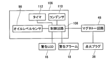
- FIG. 3 is a block diagram illustrating a configuration of an oil level sensor unit 92 according to the first embodiment. 3 is a flowchart of an oil level inspection process according to the first embodiment. It is a block diagram which shows the structure of the oil level sensor unit 106 of Example 2.
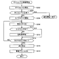
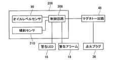
- FIG. 6 is a flowchart of an oil level inspection process according to a second embodiment. It is a block diagram which shows the structure of the oil level sensor unit 206 of Example 3.
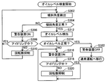
- FIG. 10 is a flowchart of an oil level inspection process according to a third embodiment.
- the portable work machine further includes an operation stop device that stops the operation of the internal combustion engine, and a second warning device that notifies the user of an abnormality in the level of the lubricating oil.
- an operation stop device that stops the operation of the internal combustion engine
- a second warning device that notifies the user of an abnormality in the level of the lubricating oil.
- the portable work machine further includes an inclination sensor that detects an inclination angle of the lubricating oil tank, and the detected value of the inclination sensor is within a predetermined range before the inspection of the liquid level of the lubricating oil. If the detected value of the tilt sensor falls within the predetermined range, the first warning device notifies the user of the abnormality and the rotational speed of the internal combustion engine by the rotational speed adjusting device until the detected value of the tilt sensor falls within the predetermined range. To suppress the rise of With such a configuration, when the lubricating oil tank is not kept horizontal during the inspection of the lubricating oil level, the user can be urged to keep the lubricating oil tank horizontal. It is possible to prevent erroneous detection of the level of the lubricating oil in the oil level sensor by checking the level of the lubricating oil only when the lubricating oil tank is maintained horizontally.
- the number of ignitions of the ignition device in the internal combustion engine is reduced from the normal time, thereby suppressing the rotation speed of the internal combustion engine from the normal time.
- FIG. 1 shows the appearance of a brush cutter 2 according to an embodiment of a portable work machine.
- the brush cutter 2 includes an operating rod 4, an engine 6 attached to the rear end of the operating rod 4, a gear head 8 attached to the front end of the operating rod 4, and a disc-shaped cutting blade attached to the gear head 8. 10, a safety cover 12 attached to the front end portion of the operation rod 4 so as to cover the cutting blade 10, and a handle 14 attached to an intermediate portion of the operation rod 4.
- the operation rod 4 has a hollow pipe shape and extends linearly.
- a drive shaft (not shown) is accommodated in the operation rod 4. Torque output from the engine 6 is transmitted to the gear head 8 via the drive shaft inside the operation rod 4 to rotate the cutting blade 10.
- the handle 14 includes a throttle lever (not shown) that performs a throttle operation of the engine 6, a stop switch (not shown) that stops the engine 6, and the like.
- the handle 14 further includes a warning LED 16 and a warning alarm 18.
- the warning LED 16 notifies the user of an abnormality in the oil level of the lubricating oil of the engine 6 by lighting.
- the warning alarm 18 notifies the user of an abnormality in the oil level of the lubricating oil of the engine 6 by sounding.
- Engine 6 is a so-called 4-stroke cycle engine. As shown in FIG. 2, the engine 6 includes an engine body 20, a fuel tank 22 that stores fuel such as gasoline, an oil pan 24 that stores lubricating oil, and a recoil starter 26 for starting the engine 6. . Further, the engine 6 includes an air cleaner 28 that filters intake air, a carburetor 30 that mixes fuel and intake air, a muffler 32 that cools and discharges high-temperature combustion gas discharged from the engine 6 to the atmosphere, and oil that will be described later A level sensor unit 92 (see FIG. 5) is provided.
- the fuel sent from the fuel tank 22 is vaporized by the carburetor 30 and then sent to the combustion chamber 34 of FIG. 3 through the air supply port.
- the fuel mixture sent into the combustion chamber 34 is ignited by the spark plug 36 and burns, and the combustion pressure of the combustion gas at that time is transmitted to the piston 38 to rotate the crankshaft 40.
- the combustion gas in the combustion chamber 34 is sent to the muffler 32 in FIG. 2 through the exhaust port, and is released into the atmosphere as exhaust gas.
- An intake valve 42 is disposed between the combustion chamber 34 and the intake port in FIG. 3, and an exhaust valve 44 is disposed between the combustion chamber 34 and the exhaust port.
- the opening and closing operations of the intake valve 42 and the exhaust valve 44 are controlled by a rocker arm 46 that operates in conjunction with the rotation of the crankshaft 40.
- the intake valve 42 and the exhaust valve 44 alternately perform one opening / closing operation while the crankshaft 40 rotates twice.
- crankshaft 40 One end (the left end in FIG. 3) of the crankshaft 40 is connected to the drive shaft inside the operation rod 4 in FIG. 1 via a clutch (not shown). The other end of the crankshaft 40 (the right end in FIG. 3) is connected to the recoil starter 26.
- a magneto circuit 48 is disposed in the vicinity of the crankshaft 40. The magneto circuit 48 generates power using the rotation of the crankshaft 40 and supplies power to the spark plug 36 and an oil level sensor unit 92 described later.
- the magnet circuit 48 includes a timing adjustment circuit (not shown) and can adjust the ignition timing of the spark plug 36. Further, the magnet circuit 48 includes a rotation speed detection circuit (not shown), and can detect the rotation speed of the crankshaft 40.
- the crankshaft 40 is provided with a valve drive gear 50 (see FIG. 4).
- the camshaft 52 (see FIG. 4), the cam follower, and the push rod 54 that follow the valve drive gear 50 prevent the rotational movement of the crankshaft 40 from being locked. This is converted into a periodic motion of the arm 46.
- FIG. 4 shows a lubricating oil circulation system of the engine 6.
- a suction part 56 for sucking lubricating oil is provided inside the oil pan 24.
- the suction part 56 has a tube 58 formed of an elastic material such as rubber, and a weight 60 with a suction port attached to the tip of the tube 58. Even when the engine 6 is used in a tilted state, the weight 60 moves in the direction of the action of gravity inside the oil pan 24, so that the suction port of the suction part 56 is always sunk below the liquid level of the lubricating oil. Include.
- the suction port of the suction part 56 communicates with the crank chamber 64 in which the crankshaft 40 is accommodated via the first oil feeding passage 62.
- a one-way valve 66 is provided in the first oil feeding passage 62.
- the opening communicating with the crank chamber 64 of the first oil feeding passage 62 is closed by the piston 38 while the piston 38 is lowered, and is opened when the piston 38 rises to near the top dead center.
- the inside of the crank chamber 64 tends to become negative pressure, and the lubricating oil is sucked up from the oil pan 24 and supplied to the crank chamber 64.
- the lubricating oil introduced into the crank chamber 64 from the first oil supply passage 62 is misted into oil mist, and lubricates the crank chamber 64.
- the lower part of the crank chamber 64 communicates with the oil pan 24 through a reed valve 75.
- a second oil feeding passage 72 is opened near the center of the oil pan 24, and the oil pan 24 communicates with the gear chamber 74 via the second oil feeding passage 72.
- the gear chamber 74 accommodates a valve drive gear 50, a cam gear 52, and the like.
- the gear chamber 74 communicates with the valve operating chamber 78 via the third oil feeding passage 76.
- the valve operating chamber 78 accommodates the rocker arm 46, the intake valve 42, the exhaust valve 44, and the like.
- the valve operating chamber 78 communicates with the crank chamber 64 via the fourth oil feeding passage 80.
- the opening communicating with the crank chamber 64 of the fourth oil feeding passage 80 is closed by the piston 38 while the piston 38 is lowered, and is opened when the piston 38 is raised to the vicinity of the top dead center.
- the crank chamber 64 tends to become positive pressure
- the reed valve 75 is opened, and the oil mist in the crank chamber 64 becomes the oil pan 24, the second It is sent to the gear chamber 74 through the oil feed passage 72.
- the oil mist sent to the gear chamber 74 is lubricated in the gear chamber 74 and then sent to the valve operating chamber 78 via the third oil feeding passage 76.
- the oil mist sent to the valve operating chamber 78 is lubricated in the valve operating chamber 78 and then sent to the crank chamber 64 via the fourth oil supply passage 80 when the piston 38 rises to near the top dead center. .
- a part of the oil mist sent from the crank chamber 64 to the oil pan 24 is liquefied and stored in the oil pan 24.
- the gear chamber 74 communicates with the crank chamber 64 via a return passage 77.
- the lubricating oil liquefied in the gear chamber 74 and accumulated in the gear chamber 74 is returned to the crank chamber 64 via the return passage 77 when the crank chamber 64 tends to have a negative pressure.
- a flow rate adjusting passage 79 is provided between the gear chamber 74 and the first oil feeding passage 62. The flow rate adjusting passage 79 adjusts the flow rate of the lubricating oil flowing through the first oil feeding passage 62 by allowing air to flow between the gear chamber 74 and the first oil feeding passage 62.
- the valve chamber 78 communicates with the air cleaner 28 via the breather passage 82.
- a one-way valve 84 is provided in the breather passage 82. Air containing oil mist and blow-by gas in the valve operating chamber 78 is sent to the air cleaner 28 via the breather passage 82.
- the oil mist is liquefied by the oil separator 86, and the lubricating oil is separated from the air containing blow-by gas.
- the blow-by gas is sent to the carburetor 30 together with air.
- the liquefied lubricating oil is sent to the crank chamber 64 via the fifth oil feeding passage 88.
- a one-way valve 90 is provided in the fifth oil supply passage 88.
- Oil level sensor 98 is attached to oil pan 24.
- the oil level sensor 98 is an electric resistance type level sensor.
- the oil level sensor 98 includes a ground electrode (not shown), an upper electrode 94 and a lower electrode 96.
- the oil level sensor 98 includes a state where the level of the lubricating oil is below the lower electrode 96, a state where the level of the lubricating oil is above the lower electrode 96 and below the upper electrode 94, and lubrication. A different signal is output for each of the states where the oil level is above the upper electrode 94.
- FIG. 5 shows the configuration of the oil level sensor unit 92.
- the oil level sensor unit 92 includes an oil level sensor 98 and a control circuit 100. Based on the signal from the oil level sensor 98, the control circuit 100 determines whether or not the level of the lubricating oil stored in the oil pan 24 is within a predetermined range. The control circuit 100 transmits an instruction regarding ignition of the spark plug 36 to the magneto circuit 48. Further, the control circuit 100 controls lighting of the warning LED 16 and sounding of the warning alarm 18 as necessary.
- step S102 the control circuit 100 detects the level of the lubricating oil inside the oil pan 24 by the oil level sensor 98.
- step S104 the control circuit 100 determines whether or not the lubricant level detected by the oil level sensor 98 is within a predetermined range. If the level of the lubricating oil is within the predetermined range (in the case of YES), the oil level inspection process is terminated and the engine 6 is shifted to normal operation. When the level of the lubricating oil is not within the predetermined range (in the case of NO), the process proceeds to step S106.
- step S106 the control circuit 100 turns on the warning LED 16 and further sounds the warning alarm 18 to notify the user of the abnormality of the lubricating oil level.
- step S108 the magneto circuit 48 determines whether or not the engine 6 is idling. Whether the engine 6 is idling is determined, for example, by comparing the rotational speed of the engine 6 with a predetermined threshold value. When the engine 6 is idling (in the case of YES), the process returns to step S106 without limiting the rotational speed of the engine 6.
- step S110 the magneto circuit 48 suppresses the increase in the rotational speed of the engine 6. While the increase in the rotational speed of the engine 6 is suppressed, even if the user performs an operation to increase the rotational speed of the engine 6 with the throttle lever, the rotational speed of the engine 6 does not increase, and noise and vibration from the engine 6 Is for low rotation. Thus, since the operation of the engine 6 is different from the user's assumption, the user can be made aware of the abnormality.
- step S110 the process returns to step S106.
- the suppression of the increase in the rotational speed of the engine 6 in step S110 can be performed by various methods. For example, by limiting the number of times of ignition by the spark plug 36 to be less than that during normal operation, an increase in the rotational speed of the engine 6 can be suppressed. Specifically, an increase in the rotational speed of the engine 6 can be suppressed by making the spark plug 36 misfire. When the rotational speed of the engine 6 is thus suppressed, the power consumed by the spark plug 36 is suppressed, and the power generated by the magnet circuit 48 can be efficiently supplied to the warning LED 16 and the warning alarm 18.
- the increase in the rotational speed of the engine 6 in step S110 can be suppressed by advancing or retarding the timing of ignition by the spark plug 36 as compared to during normal operation.
- step S106 instead of notifying the user of the abnormality of the lubricant level using both the warning LED 16 and the warning alarm 18 as described above, the abnormality is notified to the user using only the warning LED 16. Alternatively, the user may be notified of the abnormality using only the warning alarm 18.
- the level of the lubricating oil is inspected when the engine 6 is started. Normally, when the engine 6 is started, the engine 6 is kept horizontal, and therefore the oil pan 24 is kept horizontal.
- the oil level sensor 98 can appropriately detect the level of the lubricating oil.
- the level of the lubricating oil is inspected only when the engine 6 is started, and the level of the lubricating oil is not inspected during the subsequent normal operation. Since there are restrictions due to fuel capacity, worker fatigue, etc., a single operation using the brush cutter 2 usually does not take several hours. For this reason, the lubricating oil does not rapidly decrease in one operation. In particular, when the engine 6 is a four-stroke cycle engine, unlike the case of the two-stroke cycle engine, the decrease in the lubricating oil in a single operation is negligible. If it is confirmed that the oil level is appropriate, it is not necessary to check the liquid level of the lubricating oil again until the end of the work. According to the brush cutter 2 of the present embodiment, the level of the lubricating oil is inspected with the minimum necessary frequency, and if the level of the lubricating oil is abnormal, the user can be surely notified.
- the brush cutter 2 of the present embodiment in addition to notifying the user of the presence of an abnormality using a warning device such as the warning LED 16 or the warning alarm 18 when the liquid level of the lubricating oil is not within the predetermined range, The presence of the abnormality is also notified to the user by suppressing the increase in the rotational speed of the engine 6.
- the user does not necessarily watch the warning LED 16, and the noise from the engine 6 makes it difficult to hear the warning alarm 18, so the warning LED 16 and the warning alarm 18 are not heard.
- the user may not be aware of anomaly notification due to.
- the noise and vibration from the engine 6 will be different from those assumed by the user of the brush cutter 2, so that the engine 6 is in a normal state. I feel that there is no. Further, since the warning LED 16 and the warning alarm 18 are notified together with the suppression of the increase in the rotational speed of the engine 6, the user operates the operation different from the assumption of the engine 6 due to the failure of the engine 6 itself. It can be known that this is due to an abnormality in the liquid level. According to the brush cutter 2 of the present embodiment, it is possible to reliably notify the user of an abnormality in the level of the lubricating oil.
- the power for turning on the warning LED 16 and sounding the warning alarm 18 can be supplied from the magneto circuit 48. There is no need to separately provide a dedicated power source for operating the warning LED 16 and the warning alarm 18.
- the brush cutter 102 according to the present embodiment has substantially the same configuration as the brush cutter 2 according to the first embodiment. Below, only the point which is different from the brush cutter 2 of Example 1 is demonstrated in detail.
- the engine 104 of the brush cutter 102 includes an oil level sensor unit 106.
- the oil level sensor unit 106 includes an oil level sensor 98, a control circuit 108, a capacitor 110, and a timer 112.
- the capacitor 110 is charged using the power of the magnet circuit 48 while the magnet circuit 48 is generating power.
- the capacitor 110 supplies power to the control circuit 108, the warning LED 16, and the warning alarm 18 after the magneto circuit 48 finishes generating the power.
- the timer 112 counts elapse of a predetermined time.
- step S202 the control circuit 108 detects the level of the lubricating oil inside the oil pan 24 by the oil level sensor 98.
- step S204 the control circuit 108 determines whether or not the lubricant level detected by the oil level sensor 98 is within a predetermined range. When the level of the lubricating oil is within the predetermined range (in the case of YES), the oil level inspection process is terminated and the engine 104 is shifted to normal operation. If the level of the lubricating oil is not within the predetermined range (in the case of NO), the process proceeds to step S206.
- step S206 the control circuit 100 starts counting by the timer 112.
- step S208 the control circuit 100 turns on the warning LED 16 to notify the user of an oil level abnormality.
- step S210 the magnet circuit 48 determines whether or not the engine 104 is idling. If the engine 104 is idling (in the case of YES), the process proceeds to step S214 without limiting the rotational speed of the engine 104.
- step S212 the magneto circuit 48 suppresses an increase in the rotational speed of the engine 104. Thereby, even when the user does not notice the lighting of the warning LED 16, the user can feel an abnormality through noise and vibration from the engine 104. After step S212, the process proceeds to step S214.
- step S216 the magneto circuit 48 prohibits ignition by the spark plug 36. As a result, the rotation of the engine 104 ends.
- step S218 the control circuit 108 sounds the warning alarm 18 to notify the user that the operation of the engine 104 has been stopped due to an abnormality in the lubricating oil level. After step S218, the oil level inspection process is terminated.
- the warning LED 16 when an abnormality in the liquid level of the lubricating oil is detected, first, the warning LED 16 is turned on and the number of revolutions of the engine 104 is suppressed. Thereafter, when a predetermined time elapses, the rotation of the engine 104 is stopped, and the user is notified by sounding the warning alarm 18. In a state where the increase in the rotational speed of the engine 104 is suppressed, the engine 104 is still rotating, and the noise from the engine 104 makes it difficult to hear the sound of the warning alarm 18. Therefore, in such a state, the warning LED 16 is turned on, but the warning alarm 18 is not sounded.
- the electric power generated by the magnet circuit 48 is charged in the capacitor 110, and after the ignition of the ignition plug 36 is prohibited, the electric power is supplied from the capacitor 110 to the warning alarm 18. With such a configuration, it is possible to reliably supply power to the warning alarm 18. Even in the case where the capacitor 110 is not provided, since a certain amount of time is required until the rotation of the crankshaft 40 is completely stopped after the ignition of the spark plug 36 is prohibited, the magneto circuit 48 is generated during that time. It is also possible to notify the abnormality by the warning alarm 18 using the power to be used.
- the brush cutter 202 according to the present embodiment has substantially the same configuration as the brush cutter 2 according to the first embodiment. Below, only the point which is different from the brush cutter 2 of Example 1 is demonstrated in detail.
- the engine 204 of the brush cutter 202 includes an oil level sensor unit 206.
- the oil level sensor unit 206 includes an oil level sensor 98, a control circuit 208, and a tilt sensor 210.
- the tilt sensor 210 can detect the tilt angle of the oil pan 24 from the horizontal level, that is, the tilt angle of the engine 204 from the horizontal level.
- step S302 the control circuit 208 detects the tilt angle of the oil pan 24 by the tilt sensor 210.
- step S304 it is determined whether or not the oil pan 24 is kept horizontal. Specifically, it is determined whether or not the inclination angle of the oil pan 24 is within a predetermined range. If the oil pan 24 is not kept horizontal (in the case of NO), the process proceeds to step S306.
- step S306 the control circuit 208 turns on the warning LED 16 and further sounds the warning alarm 18 to notify the user of an abnormal posture of the oil pan 24.
- step S308 the magnet circuit 48 determines whether or not the engine 204 is idling. If the engine 204 is idling (in the case of YES), the process returns to step S302 without limiting the number of revolutions of the engine 204.
- step S310 the magneto circuit 48 suppresses an increase in the rotational speed of the engine 204. Thereby, even when the user does not notice the lighting of the warning LED 16 or the ringing of the warning alarm 18, the user can be notified of the abnormality through the noise and vibration from the engine 204. After step S310, the process returns to step S302.
- step S304 If the oil pan 24 is kept horizontal in step S304 (in the case of YES), the process proceeds to step S312.
- step S ⁇ b> 312 the control circuit 208 detects the level of the lubricating oil inside the oil pan 24 by the oil level sensor 98.
- step S314 the control circuit 208 determines whether or not the level of the lubricating oil detected by the oil level sensor 98 is within a predetermined range. If the level of the lubricating oil is within the predetermined range (in the case of YES), the lighting of the warning LED 16 and the ringing of the warning alarm 18 are stopped in step S322, and the engine 204 is shifted to normal operation. If it is determined in step S314 that the level of the lubricating oil is not within the predetermined range (in the case of NO), the process proceeds to step S316.
- step S316 the control circuit 208 turns on the warning LED 16 and further sounds the warning alarm 18 to notify the user of the abnormality of the lubricating oil level.
- step S3108 the magnet circuit 48 determines whether or not the engine 204 is idling. If the engine 204 is idling (in the case of YES), the process returns to step S316 without limiting the number of revolutions of the engine 204.
- step S320 the number of revolutions of the engine 204 is suppressed in the magneto circuit 48. Thereby, even when the user does not notice the lighting of the warning LED 16 or the ringing of the warning alarm 18, the user can be notified of the abnormality through the noise and vibration from the engine 204.
- step S320 the process returns to step S316.
- the engine 204 is kept horizontal when the engine 204 is started, and only when the level of the lubricating oil in the oil pan 24 is within a predetermined range. In other cases, the engine 204 is switched to the normal operation, and in addition to the notification using the warning LED 16 and the warning alarm 18, the rotational speed of the engine 204 is suppressed. Accordingly, even when the engine 204 is not kept horizontal when the engine 204 is started and therefore the oil level sensor 98 cannot properly detect the liquid level of the lubricating oil, the user can be notified of the abnormality. In this case, if the engine 204 is returned to the horizontal state and it is determined that the level of the lubricating oil is normal in that state, the engine 204 can be shifted to normal operation.
- step S310 instead of notifying the user of the abnormality using both the warning LED 16 and the warning alarm 18 as described above, only the warning LED 16 is used to notify the user of the abnormality. Or the user may be notified of the abnormality using only the warning alarm 18.
- the brush cutter 102 according to the second embodiment may be combined with the inclination sensor 210 according to the third embodiment so that the oil pan 24 is kept horizontal when the level of the lubricating oil is inspected.
Landscapes
- Engineering & Computer Science (AREA)
- Mechanical Engineering (AREA)
- General Engineering & Computer Science (AREA)
- Lubrication Details And Ventilation Of Internal Combustion Engines (AREA)
- Output Control And Ontrol Of Special Type Engine (AREA)
- Harvester Elements (AREA)
Abstract
潤滑油槽を備える内燃機関を搭載した携帯型作業機において、潤滑油槽に貯められた潤滑油の量に異常がある場合に、使用者に的確に知らせることが可能な技術を提供する。本明細書が開示する携帯型作業機は、前記潤滑油槽に貯められた潤滑油の液位を検出するオイルレベルセンサと、前記内燃機関の回転数を調整可能な回転数調整装置と、使用者に潤滑油の液位の異常を報知する第1警告装置を備えている。その携帯型作業機は、前記内燃機関の始動から前記使用者が作業を開始するまでの間に、前記潤滑油槽に貯められた潤滑油の液位の検査を自動的に行う。その携帯型作業機は、前記潤滑油の液位の検査時に、前記オイルレベルセンサの検出値が所定の範囲内に入らない場合に、前記第1警告装置によって前記使用者に異常を報知し、かつ前記回転数調整装置によって前記内燃機関の回転数の上昇を抑制する。
Description
本明細書によって開示される技術は、潤滑油槽を備える内燃機関を搭載した携帯型作業機に関する。
潤滑油槽を備える内燃機関を搭載した携帯型作業機では、潤滑油槽に貯められた潤滑油が不足する状態で作業を行うと、内燃機関の焼き付きなどの不具合を引き起こすおそれがある。しかしながら、一般にこのような携帯型作業機では、内燃機関の燃料は早く消費されるものの、内燃機関の潤滑油はそれほど早く消費されないため、携帯型作業機の使用者は、燃料の不足には関心を払うものの、潤滑油の不足に対してはあまり関心を払わないことが多い。そこで、内燃機関における潤滑油の量を自動的に検査する技術が従来から開発されている。内燃機関における潤滑油の量を自動的に検査する技術が、例えば特許文献1-6に記載されている。
潤滑油槽に貯められた潤滑油の量が不足していることを警告装置によって使用者に報知しても、使用者が気づかずに作業を行なってしまう場合がある。例えば警告灯を用いて潤滑油の量が不足していることを使用者に報知する場合、使用者がその警告灯を常に注視しているとは限らず、警告灯が点灯していても使用者が気づかない場合がある。また警告アラームを用いて使用者に報知する場合でも、内燃機関が発する騒音によって警告アラームの音が聞き取りにくくなり、警告アラームが鳴動していても使用者が気づかない場合がある。
潤滑油槽に貯められた潤滑油の量が不足する場合に内燃機関の運転を自動的に停止させれば、少なくとも潤滑油の量が不足する状態で使用者が作業を行うことを防ぐことはできる。しかしながら、この場合には、使用者は内燃機関が故障したと誤解するおそれがある。使用者に対して速やかに潤滑油を補給するよう促すためには、内燃機関が故障しているわけではなく、潤滑油槽に貯められた潤滑油の量が不足していることを、使用者に的確に知らせる必要がある。
本明細書では、潤滑油槽を備える内燃機関を搭載した携帯型作業機において、潤滑油槽に貯められた潤滑油の量に異常がある場合に、使用者に的確に知らせることが可能な技術を提供する。
本明細書は、潤滑油槽を備える内燃機関を搭載した携帯型作業機を開示する。その携帯型作業機は、前記潤滑油槽に貯められた潤滑油の液位を検出するオイルレベルセンサと、前記内燃機関の回転数を調整可能な回転数調整装置と、使用者に潤滑油の液位の異常を報知する第1警告装置を備えている。その携帯型作業機は、前記内燃機関の始動から前記使用者が作業を開始するまでの間に、前記潤滑油槽に貯められた潤滑油の液位の検査を自動的に行う。その携帯型作業機は、前記潤滑油の液位の検査時に、前記オイルレベルセンサの検出値が所定の範囲内に入らない場合に、前記第1警告装置によって前記使用者に異常を報知し、かつ前記回転数調整装置によって前記内燃機関の回転数の上昇を抑制する。
上記の携帯型作業機では、潤滑油の液位の検査時に、オイルレベルセンサの検出値が所定の範囲内に入らない場合に、第1警告装置による異常の報知に加えて、内燃機関の回転数の上昇を抑制することによっても使用者に異常の報知を行う。このような構成とすることによって、使用者が第1警告装置による異常の報知に気づかない場合でも、内燃機関からの騒音や振動が使用者の想定とは異なるものとなり、使用者に異常を感得させることができる。また、内燃機関の回転数の上昇の抑制と同時に、第1警告装置によって潤滑油の液位の異常を使用者に報知するので、異常を感得した使用者が、内燃機関が故障したと誤解することがない。潤滑油槽に貯められた潤滑油の量に異常がある場合に、使用者に的確に知らせることができる。
ここでいう「携帯型作業機」とは、使用者が携帯して作業を行う作業機のうち、内燃機関の動力を利用するものを意味しており、例えば刈払機や、草刈機、噴霧機、散布機、エンジンブロワ、集塵機などであってもよい。
ここでいう「内燃機関」は、潤滑油槽からの潤滑油によって内部の部材の潤滑を行うものであればよく、例えば4ストロークサイクルエンジンであってもよいし、分離給油式の2ストロークサイクルエンジンであってもよい。
ここでいう「潤滑油槽」とは、内燃機関の最下部に設けられたオイルパンであってもよいし、内燃機関の外部に設けられたオイルタンクであってもよい。
ここでいう「回転数調整装置」は、内燃機関の回転数の上昇を抑制することが可能なものであれば、どのようなものであってもよい。例えば、内燃機関の点火装置の点火タイミングを通常運転時よりも進角または遅角させて内燃機関の回転数を下げるものであってもよいし、内燃機関の点火装置の点火回数を通常運転時よりも低減させるものであってもよい。あるいは使用者のスロットル操作による制御を不能として、内燃機関のアイドル回転を維持させるものであってもよい。
ここでいう「第1警告手段」とは、視覚や聴覚を通じて使用者に警告を報知するものであればよく、例えば点灯によって使用者に異常を知らせる警告灯であってもよいし、鳴動によって使用者に異常を知らせる警告アラームであってもよい。
ここでいう「前記内燃機関の始動から前記使用者が作業を開始するまでの間」とは、例えば内燃機関の始動直後であってもよいし、内燃機関が始動してアイドリングの状態になってから、使用者が作業を開始するために内燃機関の回転数を上げる操作を行ったときであってもよい。
一実施形態に係る携帯型作業機は、前記内燃機関の運転を停止する運転停止装置と、前記使用者に潤滑油の液位の異常を報知する第2警告装置をさらに備えており、前記第1警告装置による異常の報知を開始してから所定時間が経過した場合に、前記運転停止装置によって前記内燃機関の運転を停止し、かつ前記第2警告装置によって前記使用者に異常を報知する。このような構成とすることによって、潤滑油槽に貯められた潤滑油の量に異常があることを、使用者により確実に知らせることができる。
一実施形態に係る携帯型作業機は、前記潤滑油槽の傾斜角度を検出する傾斜センサをさらに備えており、前記潤滑油の液位の検査前に、前記傾斜センサの検出値が所定の範囲内に入らない場合に、前記傾斜センサの検出値が前記所定の範囲内に入るまで、前記第1警告装置による前記使用者への異常の報知と、前記回転数調整装置による前記内燃機関の回転数の上昇の抑制を行う。このような構成とすることによって、潤滑油の液位の検査時に潤滑油槽が水平に維持されていない場合には、使用者に潤滑油槽を水平に維持するように促すことができる。潤滑油の液位の検査を潤滑油槽が水平に維持された状態でのみ行われるようにして、オイルレベルセンサにおける潤滑油の液位の誤検知を防止することができる。
一実施形態に係る携帯型作業機では、前記内燃機関における点火装置の点火回数を通常時よりも低減することで、前記内燃機関の回転数を通常時よりも抑制する。このような構成とすることによって、点火装置における電力の消費を抑制して、第1警告装置や第2警告装置に供給する電力を確保することができる。
(実施例1)
図1は携帯型作業機の一実施形態に係る刈払機2の外観を示している。刈払機2は、操作桿4と、操作桿4の後端部に取り付けられたエンジン6と、操作桿4の前端部に取り付けられたギヤヘッド8と、ギヤヘッド8に取り付けられた円盤状の刈刃10と、刈刃10を覆うように操作桿4の前端部に取り付けられた安全カバー12と、操作桿4の中間部に取り付けられたハンドル14を備えている。
図1は携帯型作業機の一実施形態に係る刈払機2の外観を示している。刈払機2は、操作桿4と、操作桿4の後端部に取り付けられたエンジン6と、操作桿4の前端部に取り付けられたギヤヘッド8と、ギヤヘッド8に取り付けられた円盤状の刈刃10と、刈刃10を覆うように操作桿4の前端部に取り付けられた安全カバー12と、操作桿4の中間部に取り付けられたハンドル14を備えている。
操作桿4は中空のパイプ形状を有しており、直線状に伸びている。操作桿4の内部には、ドライブシャフト(図示せず)が収容されている。エンジン6から出力されるトルクは、操作桿4の内部のドライブシャフトを経由してギヤヘッド8に伝達し、刈刃10を回転させる。ハンドル14は、エンジン6のスロットル操作を行うスロットルレバー(図示せず)、エンジン6を停止させるストップスイッチ(図示せず)等を備えている。ハンドル14はさらに、警告LED16と、警告アラーム18を備えている。警告LED16は、エンジン6の潤滑油のオイルレベルの異常を点灯によって使用者に報知する。警告アラーム18は、エンジン6の潤滑油のオイルレベルの異常を鳴動によって使用者に報知する。
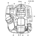
エンジン6はいわゆる4ストロークサイクルエンジンである。図2に示すように、エンジン6は、エンジン本体部20と、ガソリン等の燃料を貯える燃料タンク22と、潤滑油を貯えるオイルパン24と、エンジン6の始動用のリコイルスタータ26を備えている。さらにエンジン6は、吸入空気を濾過するエアクリーナ28と、燃料と吸入空気を混合するキャブレタ30と、エンジン6から排出される高温の燃焼ガスを冷却して大気に放出するマフラ32と、後述するオイルレベルセンサユニット92(図5参照)を備えている。
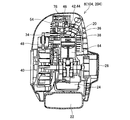
燃料タンク22から送られた燃料は、キャブレタ30で気化された後、給気ポートを通じて図3の燃焼室34に送られる。燃焼室34に送り込まれた燃料混合気は、点火プラグ36により着火されて燃焼し、その際の燃焼ガスの燃焼圧力がピストン38に伝わってクランク軸40を回転駆動させる。燃焼室34内の燃焼ガスは、排気ポートを通じて図2のマフラ32に送られ、排気ガスとして大気中に放出される。図3の燃焼室34と給気ポートの間には吸気バルブ42が配設されており、燃焼室34と排気ポートの間には排気バルブ44が配設されている。吸気バルブ42と排気バルブ44の開閉動作は、クランク軸40の回転に連動して動作するロッカーアーム46によって制御される。吸気バルブ42と排気バルブ44は、クランク軸40が2回転する間に1回の開閉動作を交互に行う。
クランク軸40の一方の端部(図3の左側の端部)は、クラッチ(図示せず)を介して図1の操作桿4の内部のドライブシャフトに連結している。クランク軸40の他方の端部(図3の右側の端部)はリコイルスタータ26に連結している。クランク軸40の近傍には、マグネトー回路48が配設されている。マグネトー回路48は、クランク軸40の回転を利用して発電し、点火プラグ36や後述するオイルレベルセンサユニット92に電力を供給する。マグネトー回路48は、タイミング調整回路(図示せず)を備えており、点火プラグ36の着火タイミングを調整可能である。さらにマグネトー回路48は、回転数検出回路(図示せず)を備えており、クランク軸40の回転数を検出可能である。クランク軸40にはバルブ駆動ギア50(図4参照)が設けられており、バルブ駆動ギア50に従動するカムギア52(図4参照)、カムフォロワ、プッシュロッド54によって、クランク軸40の回転運動がロッカーアーム46の周期運動に変換される。
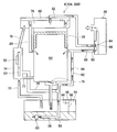
図4はエンジン6の潤滑油循環系統を示している。オイルパン24の内部には潤滑油を吸入する吸入部56が設けられている。吸入部56は、ゴム等の弾性材料により形成されたチューブ58と、チューブ58の先端部に取り付けられた吸入口付きの錘60を有している。エンジン6が傾いた状態で使用された場合でも、錘60がオイルパン24の内部で重力の作用する方向に移動することで、吸入部56の吸入口は常に潤滑油の液面の下に沈み込む。
吸入部56の吸入口は、第1送油通路62を介して、クランク軸40が収容されたクランク室64に連通している。第1送油通路62には一方向弁66が設けられている。第1送油通路62のクランク室64に連通する開口は、ピストン38が下降している間はピストン38によって閉じられており、ピストン38が上死点近傍まで上昇した時点で開かれる。ピストン38が上死点近傍まで上昇した時点では、クランク室64内は負圧化傾向となっており、潤滑油がオイルパン24から吸い上げられてクランク室64に供給される。第1送油通路62からクランク室64に導入された潤滑油は、ミスト化してオイルミストとなり、クランク室64内を潤滑する。
クランク室64の下部は、リード弁75を介してオイルパン24に連通している。オイルパン24の中央付近には第2送油通路72が開口しており、オイルパン24は第2送油通路72を介してギア室74に連通している。ギア室74には、バルブ駆動ギア50、カムギア52等が収容されている。ギア室74は、第3送油通路76を介して、動弁室78に連通している。動弁室78には、ロッカーアーム46、吸気バルブ42、排気バルブ44等が収容されている。動弁室78は、第4送油通路80を介して、クランク室64に連通している。第4送油通路80のクランク室64に連通する開口は、ピストン38が下降している間はピストン38によって閉じられており、ピストン38が上死点近傍まで上昇した時点で開かれる。ピストン38が上死点から下死点に向けて下降していくと、クランク室64が正圧化傾向となり、リード弁75が開いて、クランク室64内のオイルミストがオイルパン24、第2送油通路72を介してギア室74に送られる。ギア室74に送られたオイルミストは、ギア室74内を潤滑した後、第3送油通路76を介して動弁室78に送られる。動弁室78に送られたオイルミストは、動弁室78内を潤滑した後、ピストン38が上死点近傍まで上昇した時点で、第4送油通路80を介してクランク室64に送られる。クランク室64からオイルパン24に送られたオイルミストの一部は液化してオイルパン24内に貯められる。
ギア室74は戻し通路77を介してクランク室64と連通している。ギア室74内で液化してギア室74に溜まった潤滑油は、クランク室64が負圧化傾向となったときに、戻し通路77を介してクランク室64に戻される。また、ギア室74と第1送油通路62の間には、流量調整通路79が設けられている。流量調整通路79は、ギア室74と第1送油通路62の間で空気を流通させることで、第1送油通路62を流れる潤滑油の流量を調整する。
動弁室78はブリーザ通路82を介してエアクリーナ28に連通している。ブリーザ通路82には一方向弁84が設けられている。動弁室78内のオイルミストとブローバイガスを含んだ空気は、ブリーザ通路82を介してエアクリーナ28に送られる。
エアクリーナ28では、オイルセパレータ86によってオイルミストを液化し、ブローバイガスを含む空気から潤滑油を分離する。ブローバイガスは空気とともにキャブレタ30に送られる。液化した潤滑油は、第5送油通路88を介して、クランク室64に送られる。第5送油通路88には、一方向弁90が設けられている。
オイルパン24には、オイルレベルセンサ98が取り付けられている。オイルレベルセンサ98は電気抵抗式のレベルセンサである。オイルレベルセンサ98は、接地電極(図示せず)、上側電極94および下側電極96を備えている。オイルレベルセンサ98は、潤滑油の液面が下側電極96より下方にある状態と、潤滑油の液面が下側電極96より上方にあり、かつ上側電極94より下方にある状態と、潤滑油の液面が上側電極94より上方にある状態のそれぞれについて、異なる信号を出力する。
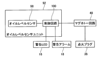
図5はオイルレベルセンサユニット92の構成を示している。オイルレベルセンサユニット92は、オイルレベルセンサ98と制御回路100で構成される。制御回路100は、オイルレベルセンサ98からの信号に基づいて、オイルパン24の内部に貯められた潤滑油の液位が、所定の範囲内に入っているか否かを判別する。制御回路100は、マグネトー回路48に点火プラグ36の着火に関する指示を送信する。また、制御回路100は、必要に応じて警告LED16の点灯と警告アラーム18の鳴動を制御する。
リコイルスタータ26によってエンジン6が始動し、マグネトー回路48で電力が生成されると、刈払機2では図6に示すオイルレベル検査処理が開始する。
ステップS102では、制御回路100が、オイルレベルセンサ98によってオイルパン24の内部の潤滑油の液位を検出する。
ステップS104では、制御回路100が、オイルレベルセンサ98で検出された潤滑油の液位が所定の範囲内に入っているか否かを判別する。潤滑油の液位が所定の範囲内に入っている場合(YESの場合)には、オイルレベル検査処理を終了して、エンジン6の通常運転へ移行する。潤滑油の液位が所定の範囲内に入っていない場合(NOの場合)には、ステップS106へ進む。
ステップS106では、制御回路100が警告LED16を点灯させて、さらに警告アラーム18を鳴動させて、使用者に潤滑油の液位の異常を報知する。
ステップS108では、マグネトー回路48において、エンジン6がアイドリング中であるか否かが判別される。エンジン6がアイドリング中であるか否かは、例えばエンジン6の回転数を所定のしきい値と比較することによって行われる。エンジン6がアイドリング中である場合(YESの場合)には、エンジン6の回転数に制限を加えることなく、ステップS106へ戻る。
ステップS110では、マグネトー回路48において、エンジン6の回転数の上昇を抑制する。エンジン6の回転数の上昇を抑制している間は、使用者がスロットルレバーによってエンジン6の回転数を上げる操作を行っても、エンジン6の回転数が上がらず、エンジン6からの騒音や振動は低回転時のものとなっている。このようにエンジン6の動作が使用者の想定とは異なるものとなることで、使用者に異常を感得させることができる。ステップS110の後、処理はステップS106へ戻る。
ステップS110におけるエンジン6の回転数の上昇の抑制は、種々の方式により行うことができる。例えば、点火プラグ36による着火の回数を、通常運転時よりも少なく制限することで、エンジン6の回転数の上昇を抑制することができる。具体的には、点火プラグ36を失火させることで、エンジン6の回転数の上昇を抑制することができる。このようにしてエンジン6の回転数を抑制する場合、点火プラグ36で消費する電力が抑制され、マグネトー回路48で生成した電力を効率よく警告LED16や警告アラーム18に供給することができる。
あるいは、ステップS110におけるエンジン6の回転数の上昇の抑制は、点火プラグ36による着火のタイミングを通常運転時よりも進角または遅角させることで行うこともできる。
なお、ステップS106では、上記のように警告LED16と警告アラーム18の双方を用いて使用者に潤滑油の液位の異常を報知する代わりに、警告LED16のみを用いて使用者に異常を報知してもよいし、警告アラーム18のみを用いて使用者に異常を報知してもよい。
本実施例の刈払機2では、エンジン6の始動時に、潤滑油の液位の検査を行う。通常は、エンジン6の始動時はエンジン6が水平に維持されており、従ってオイルパン24が水平に維持されている。オイルレベルセンサ98によって潤滑油の液位を適切に検出することができる。
本実施例の刈払機2では、エンジン6の始動時のみに潤滑油の液位の検査を行い、その後の通常運転時には潤滑油の液位の検査を行わない。燃料の容量や作業者の疲労等による制約があるため、通常は、刈払機2を用いた一度の作業が数時間にわたる事はない。そのため、一度の作業で潤滑油が急激に減少することはない。特に、エンジン6が4ストロークサイクルエンジンの場合には、2ストロークサイクルエンジンの場合とは異なり、一度の作業における潤滑油の減少はごくわずかであるから、作業を開始する前に潤滑油の液位が適正であることが確認できれば、作業の終了までの間に再び潤滑油の液位を検査する必要はない。本実施例の刈払機2によれば、必要最低限の頻度で潤滑油の液位の検査を行いつつ、潤滑油の液位に異常がある場合には確実に使用者に知らせることができる。
本実施例の刈払機2では、潤滑油の液位が所定範囲内に入っていない場合に、警告LED16や警告アラーム18などの警告装置を用いて使用者に異常の存在を報知するほかに、エンジン6の回転数の上昇を抑制することによっても使用者に異常の存在を報知する。エンジン6を始動させて作業を開始する段階では、使用者は必ずしも警告LED16を注視しておらず、またエンジン6からの騒音によって警告アラーム18の音が聞き取りにくくなるため、警告LED16や警告アラーム18による異常の報知に使用者が気づかないことがある。しかしながら、上記のようにエンジン6の回転数の上昇を抑制すると、刈払機2の使用者は、エンジン6からの騒音や振動が想定とは異なったものとなるため、エンジン6が通常の状態ではないことを感得する。また、エンジン6の回転数の上昇の抑制とともに、警告LED16や警告アラーム18による報知を行うため、使用者はエンジン6の想定とは異なる動作が、エンジン6そのものの故障によるものではなく、潤滑油の液位の異常によるものであることを知得することができる。本実施例の刈払機2によれば、使用者に潤滑油の液位の異常を確実に知らせることができる。
本実施例の刈払機2では、潤滑油の液位の異常を報知する際に、エンジン6の回転数の上昇を抑制するものの、エンジン6の回転を完全には停止させない。従って、警告LED16を点灯させたり警告アラーム18を鳴動させたりするための電力を、マグネトー回路48から供給することができる。警告LED16や警告アラーム18を動作させるための専用の電源を別途設けておく必要がない。
(実施例2)
本実施例の刈払機102は、実施例1の刈払機2とほぼ同様の構成を備えている。以下では実施例1の刈払機2と相違する点のみについて詳細に説明する。刈払機102のエンジン104は、オイルレベルセンサユニット106を備えている。
本実施例の刈払機102は、実施例1の刈払機2とほぼ同様の構成を備えている。以下では実施例1の刈払機2と相違する点のみについて詳細に説明する。刈払機102のエンジン104は、オイルレベルセンサユニット106を備えている。
図7に示すように、オイルレベルセンサユニット106は、オイルレベルセンサ98と、制御回路108と、コンデンサ110と、タイマ112により構成される。コンデンサ110は、マグネトー回路48が電力を生成している間に、マグネトー回路48の電力を利用して充電する。コンデンサ110は、マグネトー回路48が電力の生成を終了した後、制御回路108と警告LED16、警告アラーム18に電力を供給する。タイマ112は所定時間の経過をカウントする。
リコイルスタータ26によってエンジン104が始動し、マグネトー回路48で電力が生成されると、刈払機102では図8に示すオイルレベル検査処理が開始する。
ステップS202では、制御回路108が、オイルレベルセンサ98によってオイルパン24の内部の潤滑油の液位を検出する。
ステップS204では、制御回路108が、オイルレベルセンサ98で検出された潤滑油の液位が所定の範囲内に入っているか否かを判別する。潤滑油の液位が所定の範囲内に入っている場合(YESの場合)には、オイルレベル検査処理を終了して、エンジン104の通常運転へ移行する。潤滑油の液位が所定の範囲内に入っていない場合(NOの場合)には、ステップS206へ進む。
ステップS206では、制御回路100がタイマ112によるカウントを開始させる。
ステップS208では、制御回路100が警告LED16を点灯させて、使用者にオイルレベルの異常を報知する。
ステップS210では、マグネトー回路48において、エンジン104がアイドリング中であるか否かが判別される。エンジン104がアイドリング中である場合(YESの場合)には、エンジン104の回転数に制限を加えることなく、ステップS214へ進む。
ステップS212では、マグネトー回路48において、エンジン104の回転数の上昇を抑制する。これによって、使用者が警告LED16の点灯に気づかない場合でも、エンジン104からの騒音や振動を通して、使用者に異常を感得させることができる。ステップS212の後、処理はステップS214へ進む。
ステップS214では、制御回路108が、タイマ112によるカウントが終了したか否かを判別する。タイマ112によるカウントが終了していない場合(NOの場合)には、処理はステップS208へ戻る。タイマ112によるカウントが終了した場合(YESの場合)には、処理はステップS216へ進む。
ステップS216では、マグネトー回路48が、点火プラグ36による着火を禁止する。これによって、エンジン104の回転が終了する。
ステップS218では、制御回路108が、警告アラーム18を鳴動させて、使用者に潤滑油の液位の異常によりエンジン104の運転を停止した旨を報知する。ステップS218の後、オイルレベル検査処理を終了する。
本実施例の刈払機102では、潤滑油の液位の異常が検知されると、まず警告LED16の点灯による使用者への報知とともに、エンジン104の回転数を抑制する。その後、所定時間が経過すると、エンジン104の回転を停止させて、警告アラーム18の鳴動による使用者への報知を行う。エンジン104の回転数の上昇を抑制している状態では、エンジン104は依然として回転しており、エンジン104からの騒音によって警告アラーム18の音が聞き取りにくくなる。そこで、このような状態では、警告LED16の点灯は行うが、警告アラーム18の鳴動は行わない。その後、エンジン104の回転を停止させるために点火プラグ36の着火を禁止した状態では、エンジン104からの騒音は小さくなっているから、警告アラーム18の鳴動による報知を改めて行う。このような構成とすることで、使用者に潤滑油の液位の異常を確実に知らせることが出来る。
なお、本実施例ではマグネトー回路48が生成した電力をコンデンサ110に充電しておいて、点火プラグ36の着火を禁止した後はコンデンサ110から警告アラーム18に電力を供給している。このような構成とすることで、警告アラーム18に確実に電力を供給することができる。なお、コンデンサ110を備えていない構成とした場合でも、点火プラグ36の着火を禁止してからクランク軸40の回転が完全に停止するまではある程度の時間を要するから、その間にマグネトー回路48が生成する電力を用いて警告アラーム18による異常の報知を行うこともできる。
(実施例3)
本実施例の刈払機202は、実施例1の刈払機2とほぼ同様の構成を備えている。以下では実施例1の刈払機2と相違する点のみについて詳細に説明する。刈払機202のエンジン204は、オイルレベルセンサユニット206を備えている。
本実施例の刈払機202は、実施例1の刈払機2とほぼ同様の構成を備えている。以下では実施例1の刈払機2と相違する点のみについて詳細に説明する。刈払機202のエンジン204は、オイルレベルセンサユニット206を備えている。
図9に示すように、オイルレベルセンサユニット206は、オイルレベルセンサ98と、制御回路208と、傾斜センサ210により構成される。傾斜センサ210は、オイルパン24の水平からの傾斜角度、すなわちエンジン204の水平からの傾斜角度を検出可能である。
リコイルスタータ26によってエンジン204が始動し、マグネトー回路48で電力が生成されると、刈払機202では図10に示すオイルレベル検査処理が開始する。
ステップS302では、制御回路208が、傾斜センサ210によってオイルパン24の傾斜角度を検出する。
ステップS304では、オイルパン24が水平に維持されているか否かを判別する。具体的には、オイルパン24の傾斜角度が所定の範囲内に入っているか否かを判別する。オイルパン24が水平に維持されていない場合(NOの場合)には、処理はステップS306へ進む。
ステップS306では、制御回路208が警告LED16を点灯させて、さらに警告アラーム18を鳴動させて、使用者にオイルパン24の姿勢の異常を報知する。
ステップS308では、マグネトー回路48において、エンジン204がアイドリング中であるか否かが判別される。エンジン204がアイドリング中である場合(YESの場合)には、エンジン204の回転数に制限を加えることなく、ステップS302へ戻る。
ステップS310では、マグネトー回路48において、エンジン204の回転数の上昇を抑制する。これによって、使用者が警告LED16の点灯や警告アラーム18の鳴動に気づかない場合でも、エンジン204からの騒音や振動を通して、使用者に異常を知らせることができる。ステップS310の後、処理はステップS302へ戻る。
ステップS304でオイルパン24が水平に維持されている場合(YESの場合)には、処理はステップS312へ進む。ステップS312では、制御回路208が、オイルレベルセンサ98によってオイルパン24の内部の潤滑油の液位を検出する。
ステップS314では、制御回路208が、オイルレベルセンサ98で検出された潤滑油の液位が、所定の範囲内に入っているか否かを判別する。潤滑油の液位が所定の範囲内に入っている場合(YESの場合)には、ステップS322で警告LED16の点灯および警告アラーム18の鳴動を停止して、エンジン204の通常運転へ移行する。ステップS314で潤滑油の液位が所定の範囲内に入っていない場合(NOの場合)には、ステップS316へ進む。
ステップS316では、制御回路208が警告LED16を点灯させて、さらに警告アラーム18を鳴動させて、使用者に潤滑油の液位の異常を報知する。
ステップS318では、マグネトー回路48において、エンジン204がアイドリング中であるか否かが判別される。エンジン204がアイドリング中である場合(YESの場合)には、エンジン204の回転数に制限を加えることなく、ステップS316へ戻る。
ステップS320では、マグネトー回路48において、エンジン204の回転数を抑制する。これによって、使用者が警告LED16の点灯や警告アラーム18の鳴動に気づかない場合でも、エンジン204からの騒音や振動を通して、使用者に異常を知らせることができる。ステップS320の後、処理はステップS316へ戻る。
本実施例の刈払機202では、エンジン204の始動時に、エンジン204が水平に維持されており、かつオイルパン24内の潤滑油の液面が所定の範囲内に入っている場合にのみ、エンジン204の通常運転に移行し、それ以外の場合には、警告LED16および警告アラーム18を用いた報知とともに、エンジン204の回転数を抑制する。これにより、エンジン204の始動時にエンジン204が水平に維持されておらず、従ってオイルレベルセンサ98で潤滑油の液面を適切に検出できない場合も、使用者に異常を報知することができる。なお、この場合には、エンジン204を水平に戻して、その状態で潤滑油の液位が正常であると判別されれば、エンジン204の通常運転に移行することができる。
なお、本実施例の刈払機202でも、ステップS310では、上記のように警告LED16と警告アラーム18の双方を用いて使用者に異常を報知する代わりに、警告LED16のみを用いて使用者に異常を報知してもよいし、警告アラーム18のみを用いて使用者に異常を報知してもよい。
以上、本発明の具体例を詳細に説明したが、これらは例示に過ぎず、特許請求の範囲を限定するものではない。特許請求の範囲に記載の技術には、以上に例示した具体例を様々に変形、変更したものが含まれる。
例えば実施例2の刈払機102に、実施例3の傾斜センサ210を組み合わせて、潤滑油の液位を検査する際にオイルパン24の水平が確保されるように構成することもできる。
本明細書または図面に説明した技術要素は、単独であるいは各種の組合せによって技術的有用性を発揮するものであり、出願時請求項記載の組合せに限定されるものではない。また、本明細書または図面に例示した技術は複数目的を同時に達成し得るものであり、そのうちの一つの目的を達成すること自体で技術的な有用性を持つものである。
Claims (4)
- 潤滑油槽を備える内燃機関を搭載した携帯型作業機であって、
前記潤滑油槽に貯められた潤滑油の液位を検出するオイルレベルセンサと、
前記内燃機関の回転数を調整可能な回転数調整装置と、
使用者に潤滑油の液位の異常を報知する第1警告装置を備えており、
前記内燃機関の始動から前記使用者が作業を開始するまでの間に、前記潤滑油槽に貯められた潤滑油の液位の検査を自動的に行い、
前記潤滑油の液位の検査時に、前記オイルレベルセンサの検出値が所定の範囲内に入らない場合に、前記第1警告装置によって前記使用者に異常を報知し、かつ前記回転数調整装置によって前記内燃機関の回転数の上昇を抑制することを特徴とする携帯型作業機。 - 前記内燃機関の運転を停止する運転停止装置と、
前記使用者に潤滑油の液位の異常を報知する第2警告装置をさらに備えており、
前記第1警告装置による異常の報知を開始してから所定時間が経過した場合に、前記運転停止装置によって前記内燃機関の運転を停止し、かつ前記第2警告装置によって前記使用者に異常を報知することを特徴とする請求項1の携帯型作業機。 - 前記潤滑油槽の傾斜角度を検出する傾斜センサをさらに備えており、
前記潤滑油の液位の検査前に、前記傾斜センサの検出値が所定の範囲内に入らない場合に、前記傾斜センサの検出値が前記所定の範囲内に入るまで、前記第1警告装置による前記使用者への異常の報知と、前記回転数調整装置による前記内燃機関の回転数の上昇の抑制を行うことを特徴とする請求項1の携帯型作業機。 - 前記回転数調整装置が、前記内燃機関における点火装置の点火回数を通常時よりも低減することで、前記内燃機関の回転数を通常時よりも抑制することを特徴とする請求項1から3の何れか一項の携帯型作業機。
Applications Claiming Priority (2)
| Application Number | Priority Date | Filing Date | Title |
|---|---|---|---|
| JP2011065743A JP2012202257A (ja) | 2011-03-24 | 2011-03-24 | 潤滑油槽を備える内燃機関を搭載した携帯型作業機 |
| JP2011-065743 | 2011-03-24 |
Publications (1)
| Publication Number | Publication Date |
|---|---|
| WO2012127747A1 true WO2012127747A1 (ja) | 2012-09-27 |
Family
ID=46878935
Family Applications (1)
| Application Number | Title | Priority Date | Filing Date |
|---|---|---|---|
| PCT/JP2011/079315 Ceased WO2012127747A1 (ja) | 2011-03-24 | 2011-12-19 | 潤滑油槽を備える内燃機関を搭載した携帯型作業機 |
Country Status (2)
| Country | Link |
|---|---|
| JP (1) | JP2012202257A (ja) |
| WO (1) | WO2012127747A1 (ja) |
Families Citing this family (1)
| Publication number | Priority date | Publication date | Assignee | Title |
|---|---|---|---|---|
| JP6868495B2 (ja) * | 2017-07-21 | 2021-05-12 | 株式会社マキタ | 手持式作業機 |
Citations (5)
| Publication number | Priority date | Publication date | Assignee | Title |
|---|---|---|---|---|
| JPS6030428A (ja) * | 1983-07-28 | 1985-02-16 | Sanshin Ind Co Ltd | エンジンの異常警告装置 |
| JPS61123815U (ja) * | 1985-01-23 | 1986-08-04 | ||
| JPH09209737A (ja) * | 1996-01-31 | 1997-08-12 | Mitsubishi Heavy Ind Ltd | オイルレベルセンサ |
| JP2001254614A (ja) * | 2000-03-09 | 2001-09-21 | Hino Motors Ltd | 油圧警報装置 |
| JP2007535635A (ja) * | 2004-04-30 | 2007-12-06 | ワツカー コンストラクション イクイップメント アクチェンゲゼルシャフト | 内燃機関のためのオイルレベル監視装置 |
-
2011
- 2011-03-24 JP JP2011065743A patent/JP2012202257A/ja not_active Withdrawn
- 2011-12-19 WO PCT/JP2011/079315 patent/WO2012127747A1/ja not_active Ceased
Patent Citations (5)
| Publication number | Priority date | Publication date | Assignee | Title |
|---|---|---|---|---|
| JPS6030428A (ja) * | 1983-07-28 | 1985-02-16 | Sanshin Ind Co Ltd | エンジンの異常警告装置 |
| JPS61123815U (ja) * | 1985-01-23 | 1986-08-04 | ||
| JPH09209737A (ja) * | 1996-01-31 | 1997-08-12 | Mitsubishi Heavy Ind Ltd | オイルレベルセンサ |
| JP2001254614A (ja) * | 2000-03-09 | 2001-09-21 | Hino Motors Ltd | 油圧警報装置 |
| JP2007535635A (ja) * | 2004-04-30 | 2007-12-06 | ワツカー コンストラクション イクイップメント アクチェンゲゼルシャフト | 内燃機関のためのオイルレベル監視装置 |
Also Published As
| Publication number | Publication date |
|---|---|
| JP2012202257A (ja) | 2012-10-22 |
Similar Documents
| Publication | Publication Date | Title |
|---|---|---|
| JP5264198B2 (ja) | 内燃エンジンの作動方法 | |
| JP5417249B2 (ja) | 汎用エンジンの転倒検出装置 | |
| US20110073064A1 (en) | Integrally cast block and gaseous fuel injected generator engine | |
| US7325526B2 (en) | Four-stroke engine system | |
| JPS6040716A (ja) | エンジンの燃焼制御装置 | |
| US7367328B2 (en) | Four-cycle engine and motorcycle comprising four-cycle engine | |
| JP2004052724A (ja) | エンジンにおける潤滑油供給装置、およびこの装置を用いた船外機 | |
| US7325528B2 (en) | Method of operating a single cylinder two-stroke engine | |
| US8347858B2 (en) | Load condition detection apparatus for general-purpose engine | |
| US10180091B2 (en) | Breather apparatus for engine | |
| US20020179035A1 (en) | Engine control system for an outboard motor | |
| WO2012127747A1 (ja) | 潤滑油槽を備える内燃機関を搭載した携帯型作業機 | |
| US7509940B2 (en) | Marine engine | |
| JP2007239460A (ja) | 汎用エンジンのオイルレベル低下判断装置 | |
| JP2008019863A (ja) | 内燃エンジンの作動方法 | |
| JP4658815B2 (ja) | 単気筒2サイクルエンジンの作動方法 | |
| US7826955B2 (en) | General-purpose internal combustion engine | |
| JP5369070B2 (ja) | 汎用エンジンの燃料切れ判定装置 | |
| JP2017089415A (ja) | 燃料タンク内蔵型の船外機 | |
| JP2007023839A (ja) | 汎用内燃機関 | |
| JP2005220869A (ja) | 汎用エンジンのオイルセンサ | |
| JP2015094216A (ja) | エンジンの燃料供給装置及び運転方法 | |
| JP7514816B2 (ja) | エンジンのブリーザ装置 | |
| JP2008267173A (ja) | 車両並びにその制御装置および制御方法 | |
| JP5357120B2 (ja) | 汎用エンジンの燃料切れ判定装置 |
Legal Events
| Date | Code | Title | Description |
|---|---|---|---|
| 121 | Ep: the epo has been informed by wipo that ep was designated in this application |
Ref document number: 11861472 Country of ref document: EP Kind code of ref document: A1 |
|
| NENP | Non-entry into the national phase |
Ref country code: DE |
|
| 122 | Ep: pct application non-entry in european phase |
Ref document number: 11861472 Country of ref document: EP Kind code of ref document: A1 |