WO2012127610A1 - 車両の蓄熱装置 - Google Patents
車両の蓄熱装置 Download PDFInfo
- Publication number
- WO2012127610A1 WO2012127610A1 PCT/JP2011/056791 JP2011056791W WO2012127610A1 WO 2012127610 A1 WO2012127610 A1 WO 2012127610A1 JP 2011056791 W JP2011056791 W JP 2011056791W WO 2012127610 A1 WO2012127610 A1 WO 2012127610A1
- Authority
- WO
- WIPO (PCT)
- Prior art keywords
- heat storage
- heat
- amount
- materials
- state
- Prior art date
- Legal status (The legal status is an assumption and is not a legal conclusion. Google has not performed a legal analysis and makes no representation as to the accuracy of the status listed.)
- Ceased
Links
Images


Classifications
-
- F—MECHANICAL ENGINEERING; LIGHTING; HEATING; WEAPONS; BLASTING
- F28—HEAT EXCHANGE IN GENERAL
- F28D—HEAT-EXCHANGE APPARATUS, NOT PROVIDED FOR IN ANOTHER SUBCLASS, IN WHICH THE HEAT-EXCHANGE MEDIA DO NOT COME INTO DIRECT CONTACT
- F28D20/00—Heat storage plants or apparatus in general; Regenerative heat-exchange apparatus not covered by groups F28D17/00 or F28D19/00
- F28D20/02—Heat storage plants or apparatus in general; Regenerative heat-exchange apparatus not covered by groups F28D17/00 or F28D19/00 using latent heat
- F28D20/028—Control arrangements therefor
-
- F—MECHANICAL ENGINEERING; LIGHTING; HEATING; WEAPONS; BLASTING
- F02—COMBUSTION ENGINES; HOT-GAS OR COMBUSTION-PRODUCT ENGINE PLANTS
- F02G—HOT GAS OR COMBUSTION-PRODUCT POSITIVE-DISPLACEMENT ENGINE PLANTS; USE OF WASTE HEAT OF COMBUSTION ENGINES; NOT OTHERWISE PROVIDED FOR
- F02G5/00—Profiting from waste heat of combustion engines, not otherwise provided for
-
- F—MECHANICAL ENGINEERING; LIGHTING; HEATING; WEAPONS; BLASTING
- F02—COMBUSTION ENGINES; HOT-GAS OR COMBUSTION-PRODUCT ENGINE PLANTS
- F02G—HOT GAS OR COMBUSTION-PRODUCT POSITIVE-DISPLACEMENT ENGINE PLANTS; USE OF WASTE HEAT OF COMBUSTION ENGINES; NOT OTHERWISE PROVIDED FOR
- F02G5/00—Profiting from waste heat of combustion engines, not otherwise provided for
- F02G5/02—Profiting from waste heat of exhaust gases
-
- F—MECHANICAL ENGINEERING; LIGHTING; HEATING; WEAPONS; BLASTING
- F28—HEAT EXCHANGE IN GENERAL
- F28D—HEAT-EXCHANGE APPARATUS, NOT PROVIDED FOR IN ANOTHER SUBCLASS, IN WHICH THE HEAT-EXCHANGE MEDIA DO NOT COME INTO DIRECT CONTACT
- F28D20/00—Heat storage plants or apparatus in general; Regenerative heat-exchange apparatus not covered by groups F28D17/00 or F28D19/00
- F28D20/02—Heat storage plants or apparatus in general; Regenerative heat-exchange apparatus not covered by groups F28D17/00 or F28D19/00 using latent heat
-
- F—MECHANICAL ENGINEERING; LIGHTING; HEATING; WEAPONS; BLASTING
- F01—MACHINES OR ENGINES IN GENERAL; ENGINE PLANTS IN GENERAL; STEAM ENGINES
- F01P—COOLING OF MACHINES OR ENGINES IN GENERAL; COOLING OF INTERNAL-COMBUSTION ENGINES
- F01P11/00—Component parts, details, or accessories not provided for in, or of interest apart from, groups F01P1/00 - F01P9/00
- F01P11/14—Indicating devices; Other safety devices
- F01P11/20—Indicating devices; Other safety devices concerning atmospheric freezing conditions, e.g. automatically draining or heating during frosty weather
-
- Y—GENERAL TAGGING OF NEW TECHNOLOGICAL DEVELOPMENTS; GENERAL TAGGING OF CROSS-SECTIONAL TECHNOLOGIES SPANNING OVER SEVERAL SECTIONS OF THE IPC; TECHNICAL SUBJECTS COVERED BY FORMER USPC CROSS-REFERENCE ART COLLECTIONS [XRACs] AND DIGESTS
- Y02—TECHNOLOGIES OR APPLICATIONS FOR MITIGATION OR ADAPTATION AGAINST CLIMATE CHANGE
- Y02E—REDUCTION OF GREENHOUSE GAS [GHG] EMISSIONS, RELATED TO ENERGY GENERATION, TRANSMISSION OR DISTRIBUTION
- Y02E60/00—Enabling technologies; Technologies with a potential or indirect contribution to GHG emissions mitigation
- Y02E60/14—Thermal energy storage
-
- Y—GENERAL TAGGING OF NEW TECHNOLOGICAL DEVELOPMENTS; GENERAL TAGGING OF CROSS-SECTIONAL TECHNOLOGIES SPANNING OVER SEVERAL SECTIONS OF THE IPC; TECHNICAL SUBJECTS COVERED BY FORMER USPC CROSS-REFERENCE ART COLLECTIONS [XRACs] AND DIGESTS
- Y02—TECHNOLOGIES OR APPLICATIONS FOR MITIGATION OR ADAPTATION AGAINST CLIMATE CHANGE
- Y02T—CLIMATE CHANGE MITIGATION TECHNOLOGIES RELATED TO TRANSPORTATION
- Y02T10/00—Road transport of goods or passengers
- Y02T10/10—Internal combustion engine [ICE] based vehicles
- Y02T10/12—Improving ICE efficiencies
Definitions
- the present invention relates to a heat storage device for a vehicle.
- a heat storage device In such a heat storage device, in order to increase the amount of heat stored in the heat storage body while keeping the capacity of the heat storage body small, it is effective to adopt a device capable of performing latent heat storage as the heat storage body.
- the latent heat storage is heat storage using heat absorption / dissipation of the material that accompanies a change in the state of the material forming the heat storage body (for example, a change between a solid and a liquid).
- FIG. 6 shows the relationship between the state change of the heat storage body capable of latent heat storage and the temperature change of the heat storage body.
- the temperature of the heat storage body rises and reaches the melting point T.
- the heat storage body gradually changes from a solid to a liquid while maintaining the temperature at a substantially constant state.
- the temperature of a heat storage body will rise again by the provision of the said heat
- the heat stored in the heat storage body when used for heating the temperature control unit of the vehicle in a state where the heat storage body is liquid, the heat stored in the heat storage body is released.
- the temperature of the heat storage body decreases from a value higher than the melting point T to the same melting point T.
- the heat storage body gradually changes from a liquid to a solid while keeping the temperature substantially constant. And when the whole thermal storage body changes to solid, the temperature of a thermal storage body will fall again by the said heat dissipation.
- the heat storage body when the heat storage body is in a solid state and heat is stored in the heat storage body, the heat storage body is in a sensible heat storage state, and sensible heat storage is performed in the heat storage device.
- the heat storage body by applying heat to the heat storage body, the heat storage body is in a liquid state, in other words, the heat storage body is in a latent heat storage state, whereby latent heat storage is performed in the heat storage device.
- the heat storage body is partitioned into a plurality of parts, and when performing heat storage, heat from the heat source of the vehicle is sequentially applied to each partitioned heat storage body. .
- heat from the heat source of the vehicle is selectively applied to each of the heat storage bodies so that each of the partitioned heat storage bodies is in a latent heat storage state.
- at least a part of the entire heat storage body can be quickly brought into a latent heat storage state. In this way, if at least a part of the entire heat storage body can be set in the latent heat storage state, the heat storage state holding period in the heat storage device can be extended accordingly.
- Patent Document 1 when heat is stored in a heat storage body in a heat storage device, at least a part of the entire heat storage body can be quickly brought into a latent heat storage state. However, after starting the heat storage to the heat storage body, until the heat generation from the heat source of the vehicle is stopped, it is possible to set as many heat storage bodies as possible to the latent heat storage state in the heat storage state retention period in the heat storage device. In order to achieve this, the technique of Patent Document 1 has room for further improvement.
- Patent Document 1 does not describe in detail how to radiate heat from the heat storage body. Patent Document 1 also relates to how to radiate heat from the heat storage body that is intended to extend the heat storage state holding period in the heat storage device. There is room for further improvement in this technology.
- This invention is made
- the objective is to provide the thermal storage apparatus of the vehicle which can hold
- the heat storage body capable of performing latent heat storage by receiving heat from the heat source of the vehicle includes a plurality of types of heat storage materials having different melting points. Heat storage to these plural types of heat storage materials and heat release from each of these heat storage materials are controlled by the control unit.
- the control unit changes the heat storage method for the plurality of types of heat storage materials or the heat release method from the plurality of types of heat storage materials according to the heat storage amount remaining in the heat storage body. For this reason, when applying heat from a vehicle heat source to a plurality of types of heat storage materials to store heat to the heat storage bodies, the heat storage materials are most efficiently latent heat storage states according to the amount of heat storage remaining in the heat storage bodies.
- the latent heat storage state of those heat storage materials is maintained in the manner of heat dissipation that continues as long as possible according to the amount of heat storage remaining in the heat storage body. It is also possible to dissipate heat. As described above, by performing heat storage on a plurality of types of heat storage materials and heat radiation from these heat storage materials, the latent heat storage state in the plurality of types of heat storage materials can be maintained over a long period of time.
- two types of heat storage materials are provided as the plurality of types of heat storage materials.
- the control unit heats the estimated heat input amount based on the estimated heat input amount from the heat source of the vehicle to the heat storage body and the heat amount remaining in the high-melting-point heat storage material. To determine whether or not latent heat storage with a high melting point heat storage material is possible.
- the control unit gives priority to that.
- the control unit was unable to determine whether or not latent heat storage with a high melting point heat storage material was possible, or was determined to be impossible to perform latent heat storage with a high melting point heat storage material.
- heat storage to the low melting point heat storage material is given priority.
- heat storage to the heat storage body is performed so that the heat storage material having a high melting point as much as possible is in a latent heat storage state.
- heat storage to each heat storage material is performed in such a way that the heat storage body is in a latent heat storage state in which heat can be stored most effectively (latent heat storage state in which heat can be stored for the longest time). Can do.
- the control unit radiates heat preferentially from the sensible heat storage state among a plurality of types of heat storage materials when radiating heat from the heat storage body.
- heat radiation from the plurality of types of heat storage materials in the heat storage state is performed in a heat dissipation manner that continues the latent heat storage state of these heat storage materials as long as possible.
- the latent heat storage state in the heat storage materials can be maintained over a long period of time.
- the control unit is in a sensible heat storage state among a plurality of types of heat storage materials based on a required heat output amount for heating the temperature control unit of the vehicle and a heat storage amount of each of the plurality of types of heat storage materials. It is determined whether or not it is possible to satisfy the required heat output amount only with the heat storage amount of a certain heat storage material. And when it is judged that a control part can satisfy
- the control unit performs heat dissipation from the heat storage material in the latent heat storage state. Then, necessary heating is performed on the temperature control unit of the vehicle. As described above, the latent heat storage state in the heat storage material is maintained for as long as possible while the necessary heat to the temperature control unit of the vehicle cannot be obtained only by the heat storage amount of the heat storage material in the sensible heat storage state. The necessary heating can be quickly realized by releasing heat from the heat storage material in the heat storage state.
- the control unit cannot satisfy the required heat output amount for heating the temperature control unit of the vehicle only by the heat storage amount of the heat storage material in the sensible heat storage state among the plurality of types of heat storage materials.
- heat is radiated only from the heat storage material in the sensible heat storage state to heat the temperature control unit of the vehicle.
- the control unit enters the latent heat storage state. Heat is also radiated from a certain heat storage material, thereby heating the temperature control unit of the vehicle.
- the amount of heat output required for heating the temperature control unit of the vehicle varies depending on the fluctuation of the amount of heat directly applied from the heat source of the vehicle to the temperature control unit. For this reason, immediately after it is determined that it is impossible to satisfy the required heat output amount for heating the temperature control unit of the vehicle only with the heat storage amount of the heat storage material in the sensible heat storage state among the plurality of types of heat storage materials, There is also a possibility that the amount of heat directly applied from the heat source of the vehicle to the temperature adjusting unit fluctuates to the increasing side, thereby reducing the required heat output.
- the control unit performs sensible heat until a predetermined period elapses. Heat release from the heat storage material in the heat storage state is performed. And when it is judged that the above-mentioned is impossible even if the predetermined period elapses, the control unit releases heat from the heat storage material in the latent heat storage state. For this reason, heat release from the heat storage material in the latent heat storage state is performed under a situation where the required heat output is reduced immediately after it is determined that the required heat output cannot be satisfied. It can be avoided that the heat storage material shifts to the sensible heat storage state without meaning.
- the automobile is provided with a circulation circuit that circulates cooling water (heat medium) that exchanges heat with the engine 1. Circulation of the cooling water in such a circulation circuit is performed using, for example, an electric water pump 2.
- the cooling water discharged from the water pump 2 passes through the engine 1, the heater core 9, the exhaust heat recovery device 10, and the main passage 3, and then returns to the water pump 2.
- the heater core 9 is for heating the air blown to the passenger compartment by the air-conditioner mounted on the automobile by the heat of the cooling water when the passenger compartment is heated.
- the exhaust heat recovery unit 10 is for recovering heat of the exhaust gas by the cooling water through heat exchange between the cooling water passing through the exhaust water and the exhaust gas of the engine 1.
- the engine 1, the exhaust heat recovery device 10 and the like serve as heat sources, and the heat from such heat sources is transmitted to the cooling water circulating in the circulation circuit.
- This automobile heat storage device temporarily stores surplus heat from a heat source such as the engine 1 or the exhaust heat recovery unit 10, and the stored heat is a part to be heated in the automobile (hereinafter referred to as a temperature control unit). ) When used for heating.
- a temperature control unit When used for heating.
- a bypass passage 4 that bypasses the main passage 3 is provided downstream of the exhaust heat recovery device 10 and upstream of the water pump 2.
- the bypass passage 4 is provided with a heat storage container 5 insulated from the outside.
- the heat storage container 5 accommodates a heat storage body capable of performing latent heat storage and capable of causing a supercooling phenomenon.
- the inside of the heat storage container 5 is partitioned into two storage chambers 5a and 5b. Heat storage materials 6 and 7 are placed in the storage chambers 5a and 5b, respectively. Specifically, the heat storage material 6 having a low melting point is placed in the storage chamber 5a, and the heat storage material 7 having a higher melting point than that of the heat storage material 6 is placed in the storage chamber 5b.
- the heat storage body accommodated in the heat storage container 5 includes a plurality of types of heat storage materials 6 and 7 having different melting points.
- the bypass passage 4 is branched to the tributary portions 4a and 4b that pass through the storage chambers 5a and 5b, respectively, upstream of the heat storage container 5. And these branch parts 4a and 4b merge in the downstream of the thermal storage container 5.
- the heat storage container 5 of the bypass passage 4 allows high-temperature cooling water to flow into the storage chambers 5a and 5b and applies the heat of the cooling water to the heat storage materials 6 and 7, so that the heat storage materials 6 and 7 It stores excess heat from the heat source. Moreover, the heat
- the branch portion of the bypass passage 4 between the branch portion 4a and the branch portion 4b is switched between the first to fourth switching positions so as to prohibit / permit the flow of the cooling water through the branch portions 4a, 4b.
- a switching valve 11 is provided. Note that the switching valve 11 switched to any of the first to fourth switching positions functions as follows.
- the switching valve 11 switched to the first switching position prohibits the flow of cooling water through the branch part 4a and also prohibits the flow of cooling water through the branch part 4b.
- the switching valve 11 switched to the second switching position permits the circulation of the cooling water through the branch part 4a, while prohibiting the circulation of the cooling water through the branch part 4b.
- the switching valve 11 switched to the third switching position prohibits the flow of the cooling water through the branch portion 4a, and permits the flow of the cooling water through the branch portion 4b.
- the switching valve 11 switched to the fourth switching position permits the circulation of the cooling water through the branch part 4a and also permits the circulation of the cooling water through the branch part 4b.
- the heat storage device includes an electronic control device 21 that executes control of various devices mounted on the automobile.
- the electronic control unit 21 is a CPU that executes various arithmetic processes related to the above control, a ROM that stores programs and data necessary for the control, a RAM that temporarily stores the arithmetic results of the CPU, etc.
- the input / output port for inputting / outputting is provided.
- the electronic control device 21 is connected to the air conditioning control computer 20 that controls the heating of the air in the heater core 9 and the blowing of the heated air into the vehicle interior, and the navigation system 19 mounted on the automobile. Connected via (CAN).
- the electronic control unit 21 shares necessary information with the air conditioning control computer 20 and the navigation system 19 by mutual communication.
- a first temperature sensor 22 a that detects the temperature of the low-melting-point heat storage material 6 placed in the storage chamber 5 a of the heat storage container 5.
- a first inlet water temperature sensor 22b that detects the temperature of the cooling water flowing into the accommodation chamber 5a through the branch portion 4a of the bypass passage 4.
- a first outlet water temperature sensor 22c that detects the temperature of the cooling water flowing out of the storage chamber 5a through the branch portion 4a of the bypass passage 4.
- a second temperature sensor 23 a that detects the temperature of the high-melting-point heat storage material 7 placed in the storage chamber 5 b of the heat storage container 5.
- a second inlet water temperature sensor 23b that detects the temperature of the cooling water flowing into the accommodation chamber 5b through the branch portion 4b of the bypass passage 4.
- a second outlet water temperature sensor 23c that detects the temperature of the cooling water flowing out of the storage chamber 5b through the branch portion 4a of the bypass passage 4.
- An engine water temperature sensor 24 that detects the temperature of the cooling water at the outlet of the engine 1 in the circulation circuit.
- An air flow meter 25 that detects the intake air amount of the engine 1.
- a rotational speed sensor 26 that detects the rotational speed of the output shaft of the engine 1 (engine rotational speed).
- An exhaust temperature sensor 27 that detects the exhaust temperature upstream of the catalyst in the exhaust system of the engine 1.
- Connected to the output port of the electronic control unit 21 are drive circuits for various devices for driving the engine 1, a drive circuit for the water pump 2, a drive circuit for the switching valve 11, and the like.
- the electronic control unit 21 grasps the engine operating state such as the engine speed and the engine load (the amount of air taken into the combustion chamber 2 per cycle of the engine 1) based on the detection signals input from the various sensors. To do.
- the electronic control unit 21 outputs a command signal to drive circuits of various devices for driving the engine 1 connected to the output port in accordance with the engine operating state such as the engine load and the engine speed. In this manner, various operation controls such as fuel injection control, ignition timing control, and throttle opening control in the engine 1 are performed through the electronic control unit 21.
- the electronic control unit 21 also detects the temperature of the cooling water in the circulation circuit, the amount of heat required in the engine 1 and the heater core 9, the heat storage container 5 (heat storage materials 6, 7) based on detection signals input from the various sensors. ) And the amount of heat received from the exhaust heat recovery unit 10 by the cooling water.
- the electronic control device 21 outputs a command signal to the drive circuit of the water pump 2 and the drive circuit of the switching valve 11 connected to the output port according to the grasped temperature and heat quantity.
- the drive control of the water pump 2 and the switching control of the switching valve 11 in the heat storage device of the automobile are performed through the electronic control device 21.
- the electronic control device 21 that performs drive control of the water pump 2 and switching control of the switching valve 11 controls to store heat in the heat storage container 5 (heat storage materials 6 and 7) and to release heat from the heat storage container 5. It functions as a part.
- the heat storage device when the heat of the cooling water circulating in the circulation circuit can be applied to the heat storage materials 6 and 7 in the heat storage container 5, heat storage to the heat storage materials 6 and 7 is performed. Specifically, the switching valve 11 is switched to the second switching position or the third switching position, whereby the circulation of the cooling water through the branch section 4a or the branch section 4b of the bypass passage 4 is permitted and the high-temperature cooling water is supplied. The air is allowed to flow into the storage chamber 5 a or the storage chamber 5 b of the heat storage container 5 through the branch portion 4 a or the branch portion 4 b of the bypass passage 4.
- the heat storage container 5 (the heat storage materials 6 and 7) is in a heat storage state (sensible heat storage state or latent heat storage state). Retained.
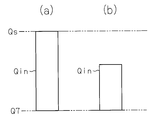
- the estimated heat input amount Qin is an estimated value of the amount of heat that can be applied to the heat storage materials 6 and 7 until the end of driving of the automobile.
- the first heat storage mode is set. That is, as shown in FIG. 2A, if the value obtained by adding the estimated heat input amount Qin to the heat storage amount Q7 of the heat storage material 7 is equal to or greater than the heat storage amount Qs that can bring the heat storage material 7 into a latent heat storage state.
- the heat storage to the heat storage materials 6 and 7 is performed in the first heat storage mode.
- the second heat storage mode is performed in which heat storage to the low melting point heat storage material 6 is performed with priority. That is, as shown in FIG. 2B, if the value obtained by adding the estimated heat input amount Qin to the heat storage amount Q7 of the heat storage material 7 is less than the heat storage amount Qs that can make the heat storage material 7 in a latent heat storage state.
- the heat storage to the heat storage materials 6 and 7 is performed in the second heat storage mode.
- heat storage to the heat storage container 5 heat storage materials 6 and 7
- the heat storage materials 6 and 7 are each stored in such a manner that the heat storage materials 6 and 7 are in a latent heat storage state in which heat can be stored most effectively (latent heat storage state in which heat can be stored for the longest time). Heat storage is performed.
- the temperature of the cooling water circulating in the circulation circuit determines completion of warming up of the engine 1. Therefore, when the cooling water is to be heated, the heat is radiated from the heat storage container 5 (heat storage materials 6 and 7). In addition, the cooling water of the circulation circuit at this time becomes a temperature control part which should be heated using the heat stored in the heat storage container 5 in the automobile.
- the switching valve 11 is switched to one of the second to fourth switching positions.
- the low-temperature cooling water passes through at least one of the accommodating chamber 5a and the accommodating chamber 5b.
- the low-temperature cooling water passes through the storage chambers 5 a and 5 b, heat is transferred from the heat storage materials 6 and 7 to the cooling water through heat exchange between the low-temperature cooling water and the heat storage materials 6 and 7.
- the heat stored in the heat storage container 5 heat storage materials 6 and 7 is released by causing the cooling water, which has been heated to a high temperature by transferring heat from the heat storage materials 6 and 7, to flow out from the heat storage container 5. Is called.
- the cooling water circulating in the circulation circuit is heated using the heat stored in the heat storage container 5.
- the temperature of the heat storage materials 6 and 7 of the heat storage container 5 is lowered as the heat is transferred to the cooling water as described above.
- the heat storage materials 6 and 7 gradually change into solids.
- the heat storage materials 6 and 7 change from liquid to solid, the heat storage materials 6 and 7 shift from the latent heat storage state to the sensible heat storage state.
- the heat storage material 7 having a high melting point is kept as long as possible to store the latent heat. It is preferable to be in a state.
- the cooling water in order to increase the temperature of the cooling water in the circulation circuit to a determination value for determining completion of warm-up of the engine 1
- the necessary heat output amount Qout is the amount of heat that needs to be released from the heat storage container 5 in order to raise the temperature of the cooling water in the circulation circuit to the above-described determination value.
- the first heat radiation mode is performed. That is, by performing heat radiation from the heat storage materials 6 and 7 in the first heat radiation mode, necessary heating is performed on the cooling water (temperature control unit of the automobile) of the circulation circuit.
- the second heat radiation mode is set in which heat is also radiated from the heat storage material in the latent heat storage state. That is, by performing heat dissipation from the heat storage materials 6 and 7 in the second heat dissipation mode, not only heat dissipation from the heat storage material in the sensible heat storage state but also heat dissipation from the heat storage material in the latent heat storage state is performed. The necessary heating is performed on the cooling water (temperature control part of the automobile) of the circulation circuit through the heat radiation.
- heat storage materials 6 and 7 when the temperature control unit of the automobile is to be heated using the heat stored in the heat storage container 5 (heat storage materials 6 and 7), in order to release the heat from the heat storage materials 6 and 7 in order to realize the heating. Heat radiation is performed preferentially from the heat storage materials 6 and 7 in the sensible heat storage state. For this reason, heat release from the heat storage container 5 (heat storage materials 6 and 7) is performed in a heat release manner that continues the latent heat storage state of the heat storage materials 6 and 7 as long as possible.
- heat storage container 5 heat storage materials 6 and 7
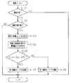
- This heat storage routine is periodically executed through the electronic control device 21 by, for example, a time interruption every predetermined time.
- S102 it is determined whether or not it is possible to predict driving until the automobile is stopped. Specifically, based on various information from the navigation system 19 operated by the vehicle occupant, it is determined in the system 19 whether or not the destination for the current driving of the vehicle is set. When the destination is set in the navigation system 19, it is determined that it is possible to predict the driving until the automobile is stopped. Thereafter, in S103, an estimated heat input amount Qin is obtained.
- the estimated heat input Qin is determined by the amount of heat given to the cooling water of the circulation circuit from the heat source of the automobile such as the engine 1 or the exhaust heat recovery device 10 until the operation of the automobile is stopped. With respect to this amount of heat, the travel distance and driving time until the vehicle is stopped are predicted based on the destination and the current position of the current vehicle driving, which is information obtained from the navigation system 19. It can be estimated by referring to the driving history (how to drive) of the automobile recorded in the RAM. And based on the amount of heat given to the cooling water estimated by the travel distance, the driving time, the driving history, etc., it can be given to the heat storage materials 6 and 7 until the end of driving of the automobile. The estimated heat input Qin representing the amount of heat can be obtained.
- Qs ⁇ Q7 is compared to determine whether the estimated heat input Qin is equal to or greater than“ Qs ⁇ Q7 ”. In other words, it is determined whether or not the heat storage material 7 having a high melting point can be in a latent heat storage state by adding heat corresponding to the estimated heat input amount Qin to the heat storage material 7.
- the heat storage material 7 can be in a latent heat storage state if heat of the estimated heat input amount Qin is added to the heat storage material 7.
- the heat storage to the heat storage materials 6 and 7 in the first heat storage mode is performed. Specifically, when the switching valve 11 is switched from the first switching position to the third switching position, the heat of the cooling water in the circulation circuit is applied to the heat storage material 7 and heat storage to the heat storage material 7 is performed. When the high-melting-point heat storage material 7 enters the latent heat storage state, the switching valve 11 is switched from the third switching position to the second switching position.
- the heat of the cooling water in the circulation circuit is given to the low-melting-point heat storage material 6, and heat storage to the heat storage material 6 is performed.
- the switching valve 11 is switched to the first switching position, thereby storing the heat.
- the materials 6 and 7 are held in the heat storage state at that time.
- the switching valve 11 when the switching valve 11 is switched from the first switching position to the second switching position, the heat of the cooling water in the circulation circuit is applied to the heat storage material 6 and heat storage to the heat storage material 6 is performed.
- the switching valve 11 When the low melting point heat storage material 6 enters the latent heat storage state, the switching valve 11 is switched from the second switching position to the third switching position. Thereby, the heat of the cooling water in the circulation circuit is given to the heat storage material 7 having a high melting point, and heat storage to the heat storage material 7 is performed.
- the switching valve 11 When the heat storage material 7 enters the latent heat storage state, or when the operation of the automobile stops before the heat storage material 7 enters the latent heat storage state, the switching valve 11 is switched to the first switching position, thereby The materials 6 and 7 are held in the heat storage state at that time.
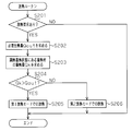
- This heat radiation routine is periodically executed through the electronic control device 21 by, for example, a time interruption every predetermined time.
- a required heat output amount Qout which is a heat amount that needs to be released from the heat storage container 5 in order to increase the temperature of the cooling water in the circulation circuit to the above-described determination value.
- the required heat output amount Qout is obtained based on the difference between the cooling water temperature detected by the engine water temperature sensor 24 and the determination value.
- the heat storage amount Qk of the heat storage materials 6 and 7 in the sensible heat storage state is obtained based on the current heat storage amount Q6 of the heat storage material 6 and the current heat storage amount Q7 of the heat storage material 7.
- the heat storage amount Q7 is obtained by a method similar to the method described in S105 of the heat storage routine.
- the heat storage amount Q6 is obtained by using the current temperature of the heat storage material 6 detected by the first temperature sensor 22a, the cumulative value of the amount of heat that has entered and exited the heat storage material 6 so far, and the like. Incidentally, the cumulative value of the amount of heat that has entered and exited the heat storage material 6 so far can be calculated using signals from the first inlet water temperature sensor 22b and the first outlet water temperature sensor 22c.
- the required heat output amount Qout is compared with the heat storage amount Qk of the heat storage materials 6 and 7 in the sensible heat storage state, and it is determined whether the heat storage amount Qk is larger than the required heat output amount Qout. . In other words, whether or not it is possible to raise the temperature of the cooling water to a determination value for determining completion of warming up of the engine 1 by releasing heat corresponding to the heat storage amount Qk to the cooling water of the circulation circuit. To be judged.
- the switching valve 11 when only the heat storage material 6 is in the sensible heat storage state and when both the heat storage materials 6 and 7 are in the sensible heat storage state, the switching valve 11 is switched from the first switching position to the second switching position. Thus, heat radiation from the low-melting-point heat storage material 6 to the cooling water of the circulation circuit is performed. When the heat dissipation from the low melting point heat storage material 6 is completed, the switching valve 11 is switched from the second switching position to the third switching position, so that the heat dissipation from the high melting point heat storage material 7 to the cooling water of the circulation circuit is performed. Done.
- the switching valve 11 When only the high-melting-point heat storage material 7 is in the sensible heat storage state, the switching valve 11 is switched from the first switching position to the third switching position, so that the high-melting-point heat storage material 7 is switched to the cooling water of the circulation circuit. Heat dissipation. When the heat dissipation from the high-melting-point heat storage material 7 is completed, the switching valve 11 is switched from the third switching position to the second switching position, so that the heat dissipation from the low-melting-point heat storage material 6 to the cooling water in the circulation circuit is performed. Done. In addition, in performing heat radiation from the heat storage materials 6 and 7 in the first heat radiation mode, it is also conceivable that both the heat storage materials 6 and 7 are in a latent heat storage state. In this case, it is preferable to radiate heat from the low-melting-point heat storage material 6 to the cooling water in the circulation circuit, and to complete heat radiation from the high-melting-point heat storage material 7 to the cooling water in the circulation circuit.
- the switching valve 11 Is switched from the first switching position to the fourth switching position, so that heat is dissipated from the low-melting-point heat storage material 6 to the cooling water in the circulation circuit, and from the high-melting-point heat storage material 7 to the cooling water in the circulation circuit. Heat dissipation is also performed.
- both the heat storage materials 6 and 7 are in a latent heat storage state.
- the switching valve 11 is switched to the second switching position to radiate heat from the low-melting-point heat storage material 6 to the cooling water in the circulation circuit, and after this is completed, the switching valve 11 is switched to the third switching position. It is preferable to radiate heat from the high melting point heat storage material 7 to the cooling water in the circulation circuit.
- the heat storage material 7 having a high melting point as much as possible is in a latent heat storage state.
- the heat storage to the heat storage materials 6 and 7 is performed.
- the heat storage materials 6 and 7 are each stored in such a manner that the heat storage materials 6 and 7 are in a latent heat storage state in which heat can be stored most effectively (latent heat storage state in which heat can be stored for the longest time).
- Heat storage is performed. Therefore, the heat storage state of the heat storage container 5 (heat storage materials 6 and 7) can be maintained over a long period.
- heat storage Heat release is preferentially performed from the materials 6 and 7 in the sensible heat storage state. For this reason, heat release from the heat storage materials 6 and 7 in the heat storage state is performed in a heat release manner that continues the latent heat storage state of the heat storage materials 6 and 7 as long as possible.
- the latent heat storage state of the heat storage materials 6 and 7 can be maintained for as long as possible.
- the heat storage state in the heat storage container 5 can be maintained over a long period.
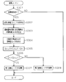
- FIG. 5 is a flowchart showing the heat radiation routine of this embodiment.
- processes S301 to S303, S306 to S307) corresponding to S201 to S206 (FIG. 4) in the heat radiation routine of the first embodiment are performed, and the processes of S304 and S305 are added to that process. Yes.
- This added processing is for obtaining the required heat output Qout in consideration of heat radiation from the heat source of the automobile to the cooling water of the circulation circuit.
- the cooling water of the circulation circuit receives heat radiation from the heat source of the automobile such as the engine 1 or the exhaust heat recovery device 10, and the temperature rises accordingly.
- the required amount of heat output Qout for heating the cooling water (the temperature adjusting unit of the automobile) so as to increase the temperature of the cooling water in the circulation circuit to a determination value for determining completion of warming up of the engine 1 is 1 and the exhaust heat recovery device 10 are affected by heat radiation from the heat source of the automobile to the cooling water. Therefore, it is preferable to obtain the required heat output amount Qout in consideration of such influence in order to improve the accuracy of the required heat output amount Qout.
- the circulation circuit starts from the automobile heat source such as the engine 1 or the exhaust heat recovery unit 10 in S304.
- the amount of heat release Qn is obtained as the amount of heat transferred to the cooling water.
- the amount of heat transferred from the engine 1 to the cooling water is estimated from parameters such as the amount of fuel consumed by the engine 1 and the amount of intake air of the engine 1, and from the exhaust heat recovery unit 10.
- the amount of heat transferred to the cooling water is estimated from parameters such as the exhaust temperature of the engine 1, the amount of fuel consumed by the engine 1, and the intake air amount of the engine 1.
- the heat radiation amount Qn is obtained based on the estimated heat amount.
- the heat release amount Qn is subtracted from the required heat output amount Qout obtained in S302, and the value after the subtraction is set as a new required heat output amount Qout.
- the required heat output amount Qout decreases as the heat release amount Qn increases. For this reason, as the heat radiation amount Qn increases, the possibility of heat radiation from the heat storage container 5 (heat storage materials 6 and 7) in the first heat radiation mode increases through the processing of S306 to S308. Furthermore, if the heat release amount Qn is equal to or greater than the required heat output amount Qout obtained in S302, the required heat output amount Qout can be satisfied by the heat release amount Qn. In this case, when performing heat radiation from the heat storage container 5 (heat storage materials 6 and 7) in the first heat radiation mode in the process of S307, the necessary heat output amount Qout is already satisfied by the heat radiation amount Qn. 11 is switched to the first switching position, so that the heat release from the heat storage container 5 is prohibited.
- the following effects can be obtained.
- the accuracy of the required heat output Qout can be improved by obtaining the required heat output Qout in consideration of heat radiation from the heat source of the automobile to the cooling water of the circulation circuit.
- heat is radiated from the heat storage container 5 to the cooling water of the circulation circuit so as to satisfy the required heat output Qout with low accuracy, there is a possibility that the heat dissipation is performed wastefully by an error of the required heat output Qout. .
- the required heat output amount Qout since the accuracy of the required heat output amount Qout can be improved as described above, the required heat output amount that is low in accuracy when performing heat radiation from the heat storage container 5 to the cooling water of the circulation circuit to satisfy the required heat output amount Qout. As in the case where the above heat dissipation is performed to satisfy Qout, it is possible to suppress the heat dissipation being performed wastefully.
- each said embodiment can also be changed as follows, for example.
- the required heat output amount Qout for heating the cooling water in the circulation circuit varies depending on the fluctuation of the heat amount directly applied to the cooling water from the heat source of the automobile such as the engine 1 or the exhaust heat recovery device 10. For this reason, immediately after it is determined that it is impossible to satisfy the required heat output amount Qout with only the heat storage amount Qk of the heat storage material in the sensible heat storage state among the heat storage materials 6 and 7, the cooling water is supplied from the heat source of the automobile. There is also a possibility that the amount of heat directly applied to the surface fluctuates to the increase side, thereby reducing the required heat output amount Qout.
- the latent heat storage is performed even though the necessary heat output Qout can be satisfied only by heat release from the heat storage material in the sensible heat storage state.
- the heat storage material in the state is radiated and the heat storage material is unnecessarily shifted to the sensible heat storage state.
- the required heat output amount Qout is the amount of heat to be radiated from the heat storage container 5 in order to increase the temperature of the cooling water in the circulation circuit to a determination value for determining completion of warming up of the engine 1
- the required heat output amount Qout may be a heat amount to be radiated from the heat storage container 5 in order to increase the temperature of the cooling water to a value necessary for heating the passenger compartment by the air conditioner (heater core 9 or the like).
- the required heat output amount Qout is reduced to an appropriate temperature.
- the amount of heat to be radiated from the heat storage container 5 may be set to increase.
- the motor generator is formed by forming the same circuit so that heat can be exchanged between the refrigerant circulating to cool the motor generator, the inverter and the like and the cooling water circulating through the circulation circuit.
- an inverter or the like may be used as an automobile heat source for storing heat in the heat storage container 5.
- the heat storage amount Q6 of the heat storage material 6 In determining the heat storage amount Q6 of the heat storage material 6, some of the first temperature sensor 22a, the first inlet water temperature sensor 22b, and the first outlet water temperature sensor 22c are omitted, and detection values from a small number of sensors are used.
- the heat storage amount Q6 may be obtained by estimation while being used.
- the heat storage amount Q7 of the heat storage material 7 In determining the heat storage amount Q7 of the heat storage material 7, some of the second temperature sensor 23a, the second inlet water temperature sensor 23b, and the second outlet water temperature sensor 23c are omitted, and detection values from a small number of sensors are used.
- the heat storage amount Q7 may be obtained by estimation while being used.
- the detection value of the first inlet water temperature sensor 22b or the detection value of the second inlet water temperature sensor 23b may be substituted with an estimated value from the detection value of the engine water temperature sensor 24. -Instead of obtaining various information (such as driving time and mileage) for obtaining the estimated heat input Qin based on the information from the navigation system 19, a dedicated setting switch operated by the passenger is provided to The above information may be obtained based on the signal.
- -It is also possible to use three or more types of heat storage materials having different melting points as the plurality of types of heat storage materials, and selectively store heat to these heat storage materials, or selectively release heat from these heat storage materials.
Landscapes
- Engineering & Computer Science (AREA)
- Mechanical Engineering (AREA)
- General Engineering & Computer Science (AREA)
- Chemical & Material Sciences (AREA)
- Combustion & Propulsion (AREA)
- Physics & Mathematics (AREA)
- Thermal Sciences (AREA)
- Air-Conditioning For Vehicles (AREA)
Abstract
Description
同図から分かるように、蓄熱体が固体である状態のもと、蓄熱体に車両の熱源からの熱を付与すると、同蓄熱体の温度が上昇して融点Tに達する。その後、蓄熱体への熱の付与を続けると、蓄熱体は温度をほぼ一定の状態に保ったまま固体から液体へと徐々に変化してゆく。そして、蓄熱体全体が液体に変化すると、上記熱の付与によって蓄熱体の温度が再び上昇してゆくようになる。
以下、本発明を自動車の蓄熱装置に具体化した第1実施形態について、図1~図4を参照して説明する。
この蓄熱装置は、自動車に搭載された各種機器の制御を実行する電子制御装置21を備えている。電子制御装置21は、上記制御に係る各種演算処理を実行するCPU、その制御に必要なプログラムやデータの記憶されたROM、CPUの演算結果等が一時記憶されるRAM、外部との間で信号を入・出力するための入・出力ポート等を備えて構成されている。なお、電子制御装置21は、ヒータコア9における空気の加熱及びその加熱された空気の車室内への送風の制御を司る空調制御コンピュータ20、及び、自動車に搭載されたナビゲーションシステム19に対し、車内ネットワーク(CAN)を通じて接続されている。電子制御装置21は、相互通信により空調制御コンピュータ20及びナビゲーションシステム19と必要な情報を共有するようになっている。
・蓄熱容器5の収容室5a内に入れられた低融点の蓄熱材6の温度を検出する第1温度センサ22a。
・バイパス通路4の支流部4aを通じて上記収容室5aから流出する冷却水の温度を検出する第1出口水温センサ22c。
・バイパス通路4の支流部4bを通じて上記収容室5bに流入する冷却水の温度を検出する第2入口水温センサ23b。
・循環回路におけるエンジン1出口での冷却水の温度を検出するエンジン水温センサ24。
・エンジン1の出力軸の回転速度(エンジン回転速度)を検出する回転速度センサ26。
電子制御装置21の出力ポートには、エンジン1を駆動するための各種機器の駆動回路、ウォータポンプ2の駆動回路、及び切換弁11の駆動回路等が接続されている。
蓄熱装置では、循環回路を循環する冷却水の熱を蓄熱容器5内の蓄熱材6,7に付与することが可能であるとき、それら蓄熱材6,7への蓄熱が行われる。詳しくは、切換弁11が第2切換位置または第3切換位置に切り換えられることにより、バイパス通路4の支流部4aまたは支流部4bを通じての冷却水の流通が許可されるとともに、高温の冷却水をバイパス通路4の支流部4aまたは支流部4bを通じて蓄熱容器5の収容室5aまたは収容室5bに流入させる。そして、その高温の冷却水が蓄熱容器5の収容室5a,5bを通過する際、同冷却水と収容室5a,5b内の蓄熱材6,7との間の熱交換を通じて、その冷却水の熱が蓄熱材6,7に伝達される。こうした熱の伝達により蓄熱材6,7が固体のままの状態で温度上昇すると、蓄熱容器5で顕熱蓄熱が行われるようになる。その後、蓄熱材6,7が更に温度上昇して固体の状態から液体に変化すると、蓄熱容器5で潜熱蓄熱が行われるようになる。そして、蓄熱容器5での蓄熱が行われた後、切換弁11を第1切換位置に切り換えると、蓄熱容器5(蓄熱材6,7)が蓄熱状態(顕熱蓄熱状態または潜熱蓄熱状態)に保持される。
(1)蓄熱ルーチン(図3)から分かるように、蓄熱容器5(蓄熱材6,7)への蓄熱を行う際には、可能な限り高融点の蓄熱材7が潜熱蓄熱状態となるように蓄熱材6,7への蓄熱が行われる。言い換えれば、蓄熱材6,7が最も効果的に熱を蓄え得る潜熱蓄熱状態(最も長時間に亘って熱を蓄え得る潜熱蓄熱状態)となるような蓄熱の仕方で、各蓄熱材6,7への蓄熱が行われる。従って、蓄熱容器5(蓄熱材6,7)の蓄熱状態を長い期間に亘って保持することができる。
次に、本発明の第2実施形態を図5に基づき説明する。
図5は、この実施形態の放熱ルーチンを示すフローチャートである。同ルーチンでは、第1実施形態の放熱ルーチンにおけるS201~206(図4)に相当する処理(S301~S303、S306~S307)が行われる他、その処理に対しS304及びS305の処理が追加されている。この追加された処理(S304及びS305)は、自動車の熱源から循環回路の冷却水への放熱も考慮して必要出熱量Qoutを求めるためのものである。
(4)自動車の熱源から循環回路の冷却水への放熱を考慮して必要出熱量Qoutを求めることで、その必要出熱量Qoutの精度を高めることができる。ここで仮に、精度の低い必要出熱量Qoutを満たすべく蓄熱容器5から循環回路の冷却水への放熱を行ったとすると、必要出熱量Qoutの誤差の分だけ上記放熱が無駄に行われるおそれがある。しかし、上述したように必要出熱量Qoutの精度を向上させることができるため、同必要出熱量Qoutを満たすべく蓄熱容器5から循環回路の冷却水への放熱を行うに当たり、精度の低い必要出熱量Qoutを満たすべく上記放熱が行われる場合のように、同放熱が無駄に行われることを抑制できる。
なお、上記各実施形態は、例えば以下のように変更することもできる。
・第2実施形態において、第2放熱モードでの蓄熱容器5からの放熱を次のように行ってもよい。すなわち、顕熱蓄熱状態にある蓄熱材の蓄熱量Qkだけでは必要出熱量Qoutを満たすことが不可能である旨判断されて第2蓄熱モードとなった時点から、予め定められた所定期間が経過するまでは、顕熱蓄熱状態にある蓄熱材のみから放熱を行って循環経路の冷却水(自動車の温度調節部)に対する加熱を行う。そして、その所定期間が経過した後にも上記蓄熱量Qkだけでは必要出熱量Qoutを満たすことが不可能である旨判断されているとき、潜熱蓄熱状態にある蓄熱材からも放熱を行い、それによっても循環回路の冷却水に対する加熱を行うようにする。
・推定入熱量Qinを求めるための各種の情報(運転時間や走行距離など)をナビゲーションシステム19からの情報に基づいて得る代わりに、乗員により操作される専用の設定スイッチ等を設けて同スイッチからの信号に基づいて上記情報を得るようにしてもよい。
Claims (5)
- 車両の熱源からの熱を受けて潜熱蓄熱を行うことの可能な蓄熱体と、
前記蓄熱体への蓄熱及び同蓄熱体からの放熱を制御する制御部と、を備え、
前記蓄熱体は融点の異なる複数種類の蓄熱材を含み、
前記制御部は、前記蓄熱体に残っている蓄熱量に応じて、前記複数種類の蓄熱材への蓄熱の仕方、または前記複数種類の蓄熱材からの放熱の仕方を変更する
車両の蓄熱装置。 - 前記複数種類の蓄熱材は、低融点の蓄熱材とそれよりも高融点の蓄熱材との二種類の蓄熱材であり、
前記制御部は、前記蓄熱体への蓄熱を行うに当たり、前記熱源から蓄熱体への推定入熱量と前記高融点の蓄熱材に残っている蓄熱量とに基づき、前記高融点の蓄熱材での潜熱蓄熱が可能と判断されたときにはそれを優先して行い、その判断が実行できなかったときや前記高融点の蓄熱材での潜熱蓄熱が不可能と判断されたときには前記低融点の蓄熱材への蓄熱を優先して行う
前記請求項1記載の車両の蓄熱装置。 - 前記制御部は、前記蓄熱体からの放熱を行うに当たり、前記複数種類の蓄熱材のうち顕熱蓄熱状態にあるものから優先的に放熱を行う
請求項1記載の車両の蓄熱装置。 - 前記制御部は、車両の温度調節部を加熱するための必要出熱量と前記複数種類の蓄熱材それぞれの蓄熱量とに基づき、前記複数種類の蓄熱材のうち顕熱蓄熱状態にある蓄熱材の蓄熱量だけで前記必要出熱量を満たすことが可能であると判断されたときには顕熱蓄熱状態にある前記蓄熱材のみから放熱を行い、前記必要出熱量を満たすことが不可能であると判断されたときには潜熱蓄熱状態にある蓄熱材からも放熱を行う
請求項3記載の車両の蓄熱装置。 - 前記制御部は、前記複数種類の蓄熱材のうち顕熱蓄熱状態にある蓄熱材の蓄熱量だけで前記必要出熱量を満たすことが不可能であると判断されたとき、その判断がされてから所定期間が経過するまでは顕熱蓄熱状態にある前記蓄熱材のみから放熱を行い、その所定期間が経過した後にも、顕熱蓄熱状態にある蓄熱材の蓄熱量だけでは前記必要出熱量を満たすことが不可能であると判断されているとき、潜熱蓄熱状態にある蓄熱材からも放熱を行う
請求項4記載の車両の蓄熱装置。
Priority Applications (5)
| Application Number | Priority Date | Filing Date | Title |
|---|---|---|---|
| PCT/JP2011/056791 WO2012127610A1 (ja) | 2011-03-22 | 2011-03-22 | 車両の蓄熱装置 |
| CN201180004499.8A CN102803695B (zh) | 2011-03-22 | 2011-03-22 | 车辆的蓄热装置 |
| US13/394,489 US9140500B2 (en) | 2011-03-22 | 2011-03-22 | Heat storage apparatus for vehicle |
| DE112011100535.0T DE112011100535B4 (de) | 2011-03-22 | 2011-03-22 | Wärmespeichergerät für ein Fahrzeug |
| JP2012504953A JP5187459B2 (ja) | 2011-03-22 | 2011-03-22 | 車両の蓄熱装置 |
Applications Claiming Priority (1)
| Application Number | Priority Date | Filing Date | Title |
|---|---|---|---|
| PCT/JP2011/056791 WO2012127610A1 (ja) | 2011-03-22 | 2011-03-22 | 車両の蓄熱装置 |
Publications (1)
| Publication Number | Publication Date |
|---|---|
| WO2012127610A1 true WO2012127610A1 (ja) | 2012-09-27 |
Family
ID=46876336
Family Applications (1)
| Application Number | Title | Priority Date | Filing Date |
|---|---|---|---|
| PCT/JP2011/056791 Ceased WO2012127610A1 (ja) | 2011-03-22 | 2011-03-22 | 車両の蓄熱装置 |
Country Status (5)
| Country | Link |
|---|---|
| US (1) | US9140500B2 (ja) |
| JP (1) | JP5187459B2 (ja) |
| CN (1) | CN102803695B (ja) |
| DE (1) | DE112011100535B4 (ja) |
| WO (1) | WO2012127610A1 (ja) |
Cited By (1)
| Publication number | Priority date | Publication date | Assignee | Title |
|---|---|---|---|---|
| JP2020112084A (ja) * | 2019-01-11 | 2020-07-27 | 本田技研工業株式会社 | 内燃機関の蓄熱放熱装置 |
Families Citing this family (11)
| Publication number | Priority date | Publication date | Assignee | Title |
|---|---|---|---|---|
| CN103291492A (zh) * | 2013-06-21 | 2013-09-11 | 高志男 | 汽车冷却水及机油的余热回收利用装置 |
| CN103334819B (zh) * | 2013-06-21 | 2015-10-14 | 高志男 | 汽车尾气的余热回收利用装置 |
| CN103306852A (zh) * | 2013-06-21 | 2013-09-18 | 高志男 | 汽车冷却水的余热回收利用装置 |
| JP6111905B2 (ja) * | 2013-07-04 | 2017-04-12 | 株式会社豊田自動織機 | 化学蓄熱装置 |
| DE102013011521A1 (de) * | 2013-07-09 | 2015-01-15 | Volkswagen Aktiengesellschaft | Antriebseinheit für ein Kraftfahrzeug |
| JP6244553B2 (ja) * | 2014-03-18 | 2017-12-13 | パナソニックIpマネジメント株式会社 | 蓄熱装置及びそれを備えた温水生成装置 |
| JP6337675B2 (ja) * | 2014-07-29 | 2018-06-06 | 株式会社デンソー | 蓄熱システム |
| US9809083B2 (en) * | 2015-02-27 | 2017-11-07 | Mahle International Gmbh | HVAC system for electric vehicle with driving range extension |
| US10471803B2 (en) * | 2016-01-27 | 2019-11-12 | Ford Global Technologies, Llc | Systems and methods for thermal battery control |
| CN105781788B (zh) * | 2016-04-29 | 2017-04-12 | 吉林大学 | 车用内燃机余热复合利用系统 |
| US10428713B2 (en) | 2017-09-07 | 2019-10-01 | Denso International America, Inc. | Systems and methods for exhaust heat recovery and heat storage |
Citations (9)
| Publication number | Priority date | Publication date | Assignee | Title |
|---|---|---|---|---|
| JPS572414A (en) * | 1980-06-09 | 1982-01-07 | Nissan Motor Co Ltd | Heat accumulator |
| JPS576296A (en) * | 1980-06-13 | 1982-01-13 | Nissan Motor Co Ltd | Heat accumulator |
| JPS61247856A (ja) * | 1985-04-26 | 1986-11-05 | Toyota Motor Corp | 蓄熱システム |
| JPH0290347U (ja) * | 1988-12-29 | 1990-07-18 | ||
| JPH06185411A (ja) * | 1992-12-17 | 1994-07-05 | Toyota Motor Corp | 内燃機関用蓄熱装置 |
| JP2008144983A (ja) * | 2006-12-06 | 2008-06-26 | Honda Motor Co Ltd | 蓄熱装置 |
| JP2008240734A (ja) * | 2001-06-05 | 2008-10-09 | Toyota Motor Corp | 蓄熱装置を備えた内燃機関 |
| JP2009257254A (ja) * | 2008-04-18 | 2009-11-05 | Toyota Central R&D Labs Inc | 車両用化学蓄熱システム |
| JP2010196974A (ja) * | 2009-02-25 | 2010-09-09 | Toyota Motor Corp | 蓄熱装置 |
Family Cites Families (22)
| Publication number | Priority date | Publication date | Assignee | Title |
|---|---|---|---|---|
| US2713252A (en) * | 1952-05-07 | 1955-07-19 | Little Inc A | Temperature control system |
| US4063546A (en) * | 1975-04-28 | 1977-12-20 | Ciba-Geigy Corporation | Heat store and installation for the utilization of solar energy |
| US4127161A (en) * | 1977-03-02 | 1978-11-28 | Energy Recycling Company | Energy storage unit and system |
| US4265223A (en) * | 1978-09-18 | 1981-05-05 | The Badger Company, Inc. | Method and apparatus for utilizing solar energy |
| US4402188A (en) * | 1979-07-11 | 1983-09-06 | Skala Stephen F | Nested thermal reservoirs with heat pumping therebetween |
| JPS56160208A (en) * | 1980-05-13 | 1981-12-09 | Nissan Motor Co Ltd | Spot heater for vehicle |
| JPH05196379A (ja) | 1991-12-24 | 1993-08-06 | Matsushita Electric Works Ltd | 蓄冷熱装置 |
| JPH05203202A (ja) | 1992-01-27 | 1993-08-10 | Matsushita Electric Works Ltd | 蓄冷熱装置 |
| US6059016A (en) * | 1994-08-11 | 2000-05-09 | Store Heat And Produce Energy, Inc. | Thermal energy storage and delivery system |
| US20010018971A1 (en) * | 1996-01-10 | 2001-09-06 | Ellen Marcie Emas | Heat storage air conditioning apparatus and heat storage estimating method |
| JP3953377B2 (ja) * | 2002-07-16 | 2007-08-08 | トヨタ自動車株式会社 | 空調装置 |
| JP4310976B2 (ja) * | 2002-08-09 | 2009-08-12 | トヨタ自動車株式会社 | 車両用空調装置 |
| JP4201011B2 (ja) * | 2006-03-27 | 2008-12-24 | トヨタ自動車株式会社 | 蓄熱装置 |
| US20080066736A1 (en) * | 2006-07-25 | 2008-03-20 | Yanong Zhu | Method and apparatus for solar energy storage system using gas and rock |
| EP2220343B8 (en) * | 2007-10-03 | 2013-07-24 | Isentropic Limited | Energy storage apparatus and method for storing energy |
| US8272432B2 (en) * | 2007-11-28 | 2012-09-25 | GM Global Technology Operations LLC | HVAC thermal storage for hybrid vehicle |
| US8584734B2 (en) * | 2008-02-11 | 2013-11-19 | Navatek, Ltd | Two material phase change energy storage system |
| US8631855B2 (en) * | 2008-08-15 | 2014-01-21 | Lighting Science Group Corporation | System for dissipating heat energy |
| EP2392500B1 (en) * | 2009-02-02 | 2014-06-04 | Toyota Jidosha Kabushiki Kaisha | Hybrid vehicle |
| JP5119190B2 (ja) | 2009-03-27 | 2013-01-16 | トヨタ自動車株式会社 | 車両の熱管理装置 |
| GB0919934D0 (en) * | 2009-11-16 | 2009-12-30 | Sunamp Ltd | Energy storage systems |
| EP2505913B1 (en) * | 2011-03-30 | 2016-03-23 | Nxp B.V. | An active thermal management device and thermal management method |
-
2011
- 2011-03-22 CN CN201180004499.8A patent/CN102803695B/zh not_active Expired - Fee Related
- 2011-03-22 JP JP2012504953A patent/JP5187459B2/ja not_active Expired - Fee Related
- 2011-03-22 DE DE112011100535.0T patent/DE112011100535B4/de not_active Expired - Fee Related
- 2011-03-22 WO PCT/JP2011/056791 patent/WO2012127610A1/ja not_active Ceased
- 2011-03-22 US US13/394,489 patent/US9140500B2/en not_active Expired - Fee Related
Patent Citations (9)
| Publication number | Priority date | Publication date | Assignee | Title |
|---|---|---|---|---|
| JPS572414A (en) * | 1980-06-09 | 1982-01-07 | Nissan Motor Co Ltd | Heat accumulator |
| JPS576296A (en) * | 1980-06-13 | 1982-01-13 | Nissan Motor Co Ltd | Heat accumulator |
| JPS61247856A (ja) * | 1985-04-26 | 1986-11-05 | Toyota Motor Corp | 蓄熱システム |
| JPH0290347U (ja) * | 1988-12-29 | 1990-07-18 | ||
| JPH06185411A (ja) * | 1992-12-17 | 1994-07-05 | Toyota Motor Corp | 内燃機関用蓄熱装置 |
| JP2008240734A (ja) * | 2001-06-05 | 2008-10-09 | Toyota Motor Corp | 蓄熱装置を備えた内燃機関 |
| JP2008144983A (ja) * | 2006-12-06 | 2008-06-26 | Honda Motor Co Ltd | 蓄熱装置 |
| JP2009257254A (ja) * | 2008-04-18 | 2009-11-05 | Toyota Central R&D Labs Inc | 車両用化学蓄熱システム |
| JP2010196974A (ja) * | 2009-02-25 | 2010-09-09 | Toyota Motor Corp | 蓄熱装置 |
Cited By (2)
| Publication number | Priority date | Publication date | Assignee | Title |
|---|---|---|---|---|
| JP2020112084A (ja) * | 2019-01-11 | 2020-07-27 | 本田技研工業株式会社 | 内燃機関の蓄熱放熱装置 |
| US11319855B2 (en) | 2019-01-11 | 2022-05-03 | Honda Motor Co., Ltd. | Heat accumulation and dissipation device for internal combustion engine |
Also Published As
| Publication number | Publication date |
|---|---|
| JP5187459B2 (ja) | 2013-04-24 |
| CN102803695B (zh) | 2014-12-03 |
| CN102803695A (zh) | 2012-11-28 |
| DE112011100535B4 (de) | 2022-02-24 |
| DE112011100535T5 (de) | 2013-01-31 |
| JPWO2012127610A1 (ja) | 2014-07-24 |
| US9140500B2 (en) | 2015-09-22 |
| US20120241121A1 (en) | 2012-09-27 |
Similar Documents
| Publication | Publication Date | Title |
|---|---|---|
| JP5187459B2 (ja) | 車両の蓄熱装置 | |
| RU2716842C2 (ru) | Система и способ (варианты) для управления тепловым аккумулятором | |
| JP5771168B2 (ja) | 蓄熱装置、空調装置及び蓄熱方法 | |
| CN101633306B (zh) | 车辆hvac和ress热力管理 | |
| JP5168853B2 (ja) | 電源システム | |
| JP4998537B2 (ja) | 車両の冷却装置 | |
| WO2011030394A1 (ja) | 車両の冷却装置 | |
| WO2017017867A1 (ja) | 冷却装置 | |
| JP7371467B2 (ja) | 車両用エネルギーマネジメントシステム | |
| JP2012081932A (ja) | 駆動用バッテリ温度調整システム | |
| JP5299324B2 (ja) | 車両の熱管理装置 | |
| JP2011148439A (ja) | 車両の制御装置 | |
| US9247678B2 (en) | Method and apparatus for controlling a coolant circuit thermally coupled to a power electronics device | |
| US10913327B2 (en) | Air conditioner for vehicle | |
| JP2022157151A (ja) | 車両空調装置 | |
| US20180370332A1 (en) | Air conditioner for vehicle | |
| JP2010144636A (ja) | 車両用暖機システム | |
| JP7245131B2 (ja) | 車両用蓄熱システム | |
| JP2010260443A (ja) | 車両の暖房装置 | |
| JP5594250B2 (ja) | 蓄熱装置 | |
| JP7679843B2 (ja) | 電池システム | |
| WO2021010281A1 (ja) | 車両用蓄熱システム | |
| JP2011218919A (ja) | 蓄熱システム | |
| JP2012122374A (ja) | 車両の熱制御装置 | |
| JP2015205668A (ja) | 車両用空気調和装置 |
Legal Events
| Date | Code | Title | Description |
|---|---|---|---|
| WWE | Wipo information: entry into national phase |
Ref document number: 201180004499.8 Country of ref document: CN |
|
| ENP | Entry into the national phase |
Ref document number: 2012504953 Country of ref document: JP Kind code of ref document: A |
|
| WWE | Wipo information: entry into national phase |
Ref document number: 13394489 Country of ref document: US |
|
| WWE | Wipo information: entry into national phase |
Ref document number: 112011100535 Country of ref document: DE Ref document number: 1120111005350 Country of ref document: DE |
|
| 121 | Ep: the epo has been informed by wipo that ep was designated in this application |
Ref document number: 11861637 Country of ref document: EP Kind code of ref document: A1 |
|
| 122 | Ep: pct application non-entry in european phase |
Ref document number: 11861637 Country of ref document: EP Kind code of ref document: A1 |