WO2012127543A1 - インクジェット印刷装置 - Google Patents
インクジェット印刷装置 Download PDFInfo
- Publication number
- WO2012127543A1 WO2012127543A1 PCT/JP2011/005351 JP2011005351W WO2012127543A1 WO 2012127543 A1 WO2012127543 A1 WO 2012127543A1 JP 2011005351 W JP2011005351 W JP 2011005351W WO 2012127543 A1 WO2012127543 A1 WO 2012127543A1
- Authority
- WO
- WIPO (PCT)
- Prior art keywords
- suction
- printing apparatus
- ink
- inkjet
- housing
- Prior art date
- Legal status (The legal status is an assumption and is not a legal conclusion. Google has not performed a legal analysis and makes no representation as to the accuracy of the status listed.)
- Ceased
Links
Images




Classifications
-
- B—PERFORMING OPERATIONS; TRANSPORTING
- B41—PRINTING; LINING MACHINES; TYPEWRITERS; STAMPS
- B41J—TYPEWRITERS; SELECTIVE PRINTING MECHANISMS, i.e. MECHANISMS PRINTING OTHERWISE THAN FROM A FORME; CORRECTION OF TYPOGRAPHICAL ERRORS
- B41J2/00—Typewriters or selective printing mechanisms characterised by the printing or marking process for which they are designed
- B41J2/005—Typewriters or selective printing mechanisms characterised by the printing or marking process for which they are designed characterised by bringing liquid or particles selectively into contact with a printing material
- B41J2/01—Ink jet
- B41J2/135—Nozzles
- B41J2/165—Prevention or detection of nozzle clogging, e.g. cleaning, capping or moistening for nozzles
- B41J2/16517—Cleaning of print head nozzles
- B41J2/1652—Cleaning of print head nozzles by driving a fluid through the nozzles to the outside thereof, e.g. by applying pressure to the inside or vacuum at the outside of the print head
- B41J2/16532—Cleaning of print head nozzles by driving a fluid through the nozzles to the outside thereof, e.g. by applying pressure to the inside or vacuum at the outside of the print head by applying vacuum only
-
- B—PERFORMING OPERATIONS; TRANSPORTING
- B41—PRINTING; LINING MACHINES; TYPEWRITERS; STAMPS
- B41J—TYPEWRITERS; SELECTIVE PRINTING MECHANISMS, i.e. MECHANISMS PRINTING OTHERWISE THAN FROM A FORME; CORRECTION OF TYPOGRAPHICAL ERRORS
- B41J2/00—Typewriters or selective printing mechanisms characterised by the printing or marking process for which they are designed
- B41J2/005—Typewriters or selective printing mechanisms characterised by the printing or marking process for which they are designed characterised by bringing liquid or particles selectively into contact with a printing material
- B41J2/01—Ink jet
- B41J2/135—Nozzles
- B41J2/165—Prevention or detection of nozzle clogging, e.g. cleaning, capping or moistening for nozzles
- B41J2/16505—Caps, spittoons or covers for cleaning or preventing drying out
- B41J2/16508—Caps, spittoons or covers for cleaning or preventing drying out connected with the printer frame
-
- B—PERFORMING OPERATIONS; TRANSPORTING
- B41—PRINTING; LINING MACHINES; TYPEWRITERS; STAMPS
- B41J—TYPEWRITERS; SELECTIVE PRINTING MECHANISMS, i.e. MECHANISMS PRINTING OTHERWISE THAN FROM A FORME; CORRECTION OF TYPOGRAPHICAL ERRORS
- B41J2/00—Typewriters or selective printing mechanisms characterised by the printing or marking process for which they are designed
- B41J2/005—Typewriters or selective printing mechanisms characterised by the printing or marking process for which they are designed characterised by bringing liquid or particles selectively into contact with a printing material
- B41J2/01—Ink jet
- B41J2/135—Nozzles
- B41J2/165—Prevention or detection of nozzle clogging, e.g. cleaning, capping or moistening for nozzles
- B41J2/16585—Prevention or detection of nozzle clogging, e.g. cleaning, capping or moistening for nozzles for paper-width or non-reciprocating print heads
-
- B—PERFORMING OPERATIONS; TRANSPORTING
- B41—PRINTING; LINING MACHINES; TYPEWRITERS; STAMPS
- B41J—TYPEWRITERS; SELECTIVE PRINTING MECHANISMS, i.e. MECHANISMS PRINTING OTHERWISE THAN FROM A FORME; CORRECTION OF TYPOGRAPHICAL ERRORS
- B41J2/00—Typewriters or selective printing mechanisms characterised by the printing or marking process for which they are designed
- B41J2/005—Typewriters or selective printing mechanisms characterised by the printing or marking process for which they are designed characterised by bringing liquid or particles selectively into contact with a printing material
- B41J2/01—Ink jet
- B41J2/135—Nozzles
- B41J2/165—Prevention or detection of nozzle clogging, e.g. cleaning, capping or moistening for nozzles
- B41J2/16517—Cleaning of print head nozzles
- B41J2/1652—Cleaning of print head nozzles by driving a fluid through the nozzles to the outside thereof, e.g. by applying pressure to the inside or vacuum at the outside of the print head
- B41J2/16523—Waste ink transport from caps or spittoons, e.g. by suction
-
- B—PERFORMING OPERATIONS; TRANSPORTING
- B41—PRINTING; LINING MACHINES; TYPEWRITERS; STAMPS
- B41J—TYPEWRITERS; SELECTIVE PRINTING MECHANISMS, i.e. MECHANISMS PRINTING OTHERWISE THAN FROM A FORME; CORRECTION OF TYPOGRAPHICAL ERRORS
- B41J25/00—Actions or mechanisms not otherwise provided for
- B41J2025/008—Actions or mechanisms not otherwise provided for comprising a plurality of print heads placed around a drum
Definitions
- the present invention relates to an inkjet printing apparatus including a plurality of inkjet heads.
- an ink jet head by suction is used to eliminate a printing defect called nozzle missing due to part of the ink jet nozzles being clogged. Cleaning (suction purge) is performed.
- the ink jet recording apparatus described in Patent Document 1 includes a cap that individually covers the ejection port group (ink jet head), and a pump that draws ink into the cap by suction from the ink ejection port (ink jet nozzle).
- an open / close valve is individually provided in a connection path that connects each cap and pump.
- the ink jet recording apparatus includes, for example, an ink jet nozzle that does not eject ink by selectively opening an on-off valve provided in a connection path communicating with each cap of the ejection port group (ink jet head). Only the cap that covers the inkjet head can be connected to a pump to perform suction suction for individual suction.
- an inkjet printing apparatus including a cleaning mechanism capable of performing overall suction for collectively sucking a plurality of inkjet heads and individual suction only for one inkjet head (patent) Reference 2).
- This cleaning mechanism uses an individual suction cap in which only one of the caps individually covering a plurality of inkjet heads is connected to the pump via a tube, and a tube that is branched and connected to a plurality of other caps.
- a cap connected to the pump, a first on-off valve for simultaneously switching the suction operations of the plurality of caps, and a second on-off valve for switching only the suction operation of the individual suction cap.
- the plurality of inkjet heads are all covered with caps, and the first and second on-off valves are opened to perform the suction. Also, when performing individual suction, cover only one inkjet head with a cap for individual suction, close the first on-off valve and open the second on-off valve, and then the ink jet head you want to perform suction Individual suction is possible.
- the present invention provides an ink jet printing apparatus capable of reducing ink consumption and quickly cleaning an ink jet head while having a simple configuration. With the goal.
- the present invention has the following configuration. That is, the present invention provides a plurality of ink jet heads in which a plurality of ink jet nozzles are arranged, a plurality of caps corresponding to each of the plurality of ink jet heads, and a plurality of conduits respectively connected to the plurality of caps.
- a communication portion that communicates with the suction port is formed therein, a switching portion that is rotatably supported by being connected to a driving means, and a housing that includes the switching portion, wherein the plurality of pipe lines
- a plurality of external suction ports connectable with the internal suction port connected to a suction path for sucking the interior of the housing.
- a housing disposed at an equal distance from the center, and selecting the suction port as the suction means by rotating the switching portion to a position where the communication path is connected to one of the plurality of external suction ports.
- a connection switching means for connection to each other.
- a housing in which a plurality of external suction ports connectable to a plurality of ducts and an internal suction port connected to a suction path for sucking the inside of the housing are arranged at an equal distance from the rotation center of the switching unit. And a connection switching means for selectively connecting any one of the plurality of external suction ports to the suction means by rotating the switching portion. Therefore, when the switching unit is connected to one of the external suction ports, ink is sucked from one of the plurality of inkjet nozzles, and when the switching unit is connected to the internal suction port, the inside of the housing is sucked.
- the ink is sucked from all the ink jet nozzles, so that the ink consumption due to the suction purging of the ink jet head which does not require the suction purge can be reduced.
- the housing is provided with a suction port of a suction path for sucking the inside of the housing at a lower part.
- the housing includes a plurality of external suction ports in a radial shape.
- the housing is provided with the plurality of external suction ports in a coaxial manner.
- a suction path for sucking the inside of the housing is formed in the housing.
- the switching portion has an L shape, one end side is rotated by the driving unit, and the other end side is connected to each of the plurality of external suction ports.
- the switching portion has a crank shape, one end side is rotated by the driving means, and the other end side is connected to each of the plurality of external suction ports.
- the housing includes a hermetic bearing portion at the rotation center of the switching portion.
- a plurality of the plurality of inkjet heads are provided for a single ink color.
- a plurality of external suction ports connectable to a plurality of conduits and an internal suction port connected to a suction path for suctioning the inside of the housing are arranged at an equal distance from the rotation center of the switching unit.
- the housing is provided with connection switching means for selectively connecting any one of the plurality of external suction ports to the suction means by rotating the switching portion. Therefore, when the switching unit is connected to one of the external suction ports, ink is sucked from one of the plurality of inkjet nozzles, and when the switching unit is connected to the internal suction port, the inside of the housing is sucked.
- the ink is sucked from all the ink jet nozzles, so that the ink consumption due to the suction purging of the ink jet head which does not require the suction purge can be reduced.
- the suction port of the suction path for sucking the inside of the housing is provided at the lower part of the housing, the ink accumulated in the housing can be sucked reliably.
- the housing is formed with a suction path for sucking the inside of the housing, the housing can be made compact.
- FIG. 1 is a diagram for explaining an inkjet printing apparatus 100.
- FIG. FIG. 4 is a diagram for explaining a discharge unit 3.
- FIG. 3 is a diagram for explaining a discharge unit 3. It is a figure for demonstrating the external structure of the connection switching part. It is a figure for demonstrating the internal structure of the connection switching part.
- 6 is a diagram for explaining suction of the inkjet nozzle group 30 by the operation of a connection switching unit 315.
- FIG. It is a figure for demonstrating another form of the connection switching part. It is a figure for demonstrating housing 315'h of the connection switching part 315.
- FIG. 1 is a view for explaining an ink jet printing apparatus 100 according to the present invention.
- the ink jet printing apparatus 100 is a printing apparatus that performs printing by ejecting ink onto a conveyed roll paper.
- the ink jet printing apparatus 100 includes a control unit 1, a transport unit 2, a discharge unit 3, a drying unit 4, and an inspection unit 5.
- the control unit 1 is for controlling the entire inkjet printing apparatus 100.
- the controller 1 transports the sheet 9 by the transport unit 2, ejects ink onto the sheet 9 by the ejection unit 3, or performs a cleaning operation in the ejection unit 3, dries the sheet 9 on which ink is ejected by the drying unit 4, and inspects In this way, printing of the print image of the paper 9 is controlled to realize printing of the ink jet printing apparatus 100 on the paper 9.
- the transport unit 2 is configured to transport the paper 9 in the inkjet printing apparatus 100, and includes a paper storage unit 20, a driving roller 21, and a support roller 22.
- the paper storage unit 20 is for storing the paper 9 that is roll paper for printing.
- the paper storage unit 20a stores the paper 9 before printing, and the paper storage unit 20b stores the paper 9 after printing. Storing.
- the paper 9 drawn out from the paper storage unit 20a is conveyed by the drive rollers 21a and 21b through the discharge unit 3, the drying unit 4 and the inspection unit 5 while being supported by the support roller 22, and is wound around the paper storage unit 20b.
- the ejection unit 3 receives ink supplied from an ink tank (not shown), ejects ink according to a drive signal generated by the control unit 1 based on the image information, and performs printing on the paper 9.
- the discharge unit 3 includes a plurality of inkjet nozzle groups 30k, 30c, 30m, and 30y.
- the inkjet nozzle groups 30k, 30c, 30m, and 30y are orthogonal to the conveyance direction of the paper 9, and a discharge width that is greater than the conveyance width of the paper 9 is realized by arranging a large number of nozzles. Since the discharge unit 3 has such a configuration, the discharge unit 3 performs printing by one discharge without performing reciprocal scanning in the conveyance width direction of the paper 9.
- the number of inkjet nozzle groups in the ejection unit 3 is not limited to four, and the number of inkjet nozzle groups may be one for monochromatic ejection, or 5 to perform ejection with a special color added. Two or more inkjet nozzle groups may be provided.
- the drying unit 4 fixes the ink by evaporating the solvent (mainly water) of the ink by applying heat to the paper 9 after printing by the discharge unit 3 using a heater, a dryer, or the like.
- the ejection by the ejection unit 3 is a radiation curable ink such as a UV curable ink
- the drying unit 4 has a configuration for performing radiation oscillation, thereby fixing (curing) the ink on the paper 9. .
- the inspection unit 5 captures a print image in order for the control unit 1 to determine whether or not the printing performed on the paper 9 is good.
- the inspection unit 5 captures a printed image printed on the conveyed paper 9 by a CCD line sensor or a CCD camera, and transmits imaging information to the control unit 1.
- the control unit 1 determines whether or not the printing is good by comparing the image information used for performing the ink discharge and the photographing information to determine whether or not there is a discharge failure in the discharge unit 3. be able to.
- the ejection failure refers to non-ejection of ink from the nozzle, defective ejection of ink droplets, ink droplet size failure, and the like. If the control unit 1 determines that such ejection failure exists in the ejection unit 3, the control unit 1 1 executes cleaning of the discharge unit 3.
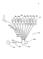
- FIG. 2 and FIG. 3 are diagrams for explaining an outline of the discharge unit 3 that performs cleaning.
- FIG. 2 shows a state in which the ejection unit 3 performs printing on the paper 9
- FIG. 3 shows a state in which the ejection unit 3 performs cleaning.
- the discharge unit 3 includes a cleaning unit 31 having a suction cap 311, a suction tube 312, an electromagnetic open / close valve 313, a suction pump 314, a connection switching unit 315, and a suction pipe 316 in order to clean the inkjet nozzle group 30. ing.
- ink jet heads 30a to 30h are arranged in order to form one ink jet nozzle group 30.
- the number of inkjet heads arranged to form the inkjet nozzle group 30 is not limited to eight.
- one cleaning unit 31 corresponding to one inkjet nozzle group 30 is provided, but a plurality of cleaning units 31 corresponding to each of the plurality of inkjet nozzle groups 30 are ejected. Part 3 is provided.
- the suction cap 311 covers the inkjet nozzle group 30 in order to prevent the nozzle from drying and contamination.
- the suction cap 311 provided with the suction tube 312 connected to the suction pump 314 performs the coating as shown in FIG. 3 when the inkjet nozzle group 30 descends based on the control of the control unit 1, and the inkjet nozzle group Suction for eliminating 30 ink clogs can be performed.
- suction caps 311a to 311h are provided corresponding to the inkjet heads 30a to 30h.
- the suction tube 312 is connected to the suction cap 311 as described above. As shown in FIG. 3, the ink sucked from the inkjet nozzle group 30 covered by the suction cap 311 passes through the suction tube 312 and is sucked by the suction pump 314. Sucked.
- suction tubes 312a to 312h are provided corresponding to the suction caps 311a to 311h, and are connected to the connection switching unit 315 so as to be sucked.
- the suction tube 312z is not directly connected to the suction cap 311. However, the suction tube 312z is connected to the connection switching unit 315 so as to perform suction inside the connection switching unit 315, so that ink suction from the suction caps 311a to 311h is performed. (Details will be described later).
- the electromagnetic on-off valve 313 is provided in a suction line 316 that connects the suction pump 314 and the connection switching unit 315. Under the control of the control unit 1, the electromagnetic on-off valve 313 closes the suction pipe 316 while the discharge process to the paper 9 by the inkjet nozzle group 30 is performed as shown in FIG. 2. As shown in FIG. 3, the inkjet nozzle group 30 is covered with a suction cap 311, and the connection switching unit 315 switches and connects the suction pump 314 and the suction tubes 312 a to 312 h to connect ink from the inkjet heads 30 a to 30 h. When suction is performed, the electromagnetic on-off valve 313 opens the suction pipe 316 under the control of the control unit 1 (details will be described later).
- connection switching unit 315 switches to and connects to the suction tube 312z
- the electromagnetic on-off valve 313 is controlled by the control unit 1 even when the suction pump 314 sucks ink collectively from the inkjet heads 30a to 30h.
- the suction line 316 is opened (details will be described later).
- the suction pump 314 sucks ink from the inkjet nozzle group 30 through the suction conduit 316, the connection switching unit 315, the suction tubes 312a to 312h, or 312z, and the suction cap 311 in the state shown in FIG.
- the suction pump 314 When the suction pump 314 generates a negative pressure, the ink flows out from the inkjet nozzle group 30.
- the ink that has flowed out due to the negative pressure is accumulated in a waste liquid tank (not shown) of the inkjet printing apparatus 100 via the suction cap 311, the suction tube 312, the connection switching unit 315, the suction pipe 316, and the suction pump 314.
- connection switching unit 315 sucks the ink-jet heads 30a to 30h constituting the ink-jet nozzle group 30 individually or sucks the ink-jet heads 30a to 30h together when sucking ink from the ink-jet nozzle group 30 by the suction pump 314. Therefore, based on the control of the control unit 1, the suction conduit 316 and the suction tubes 312a to 312h or 312z are switched.
- connection switching unit 315 Details of the connection switching unit 315 will be described with reference to FIGS. 4 and 5.
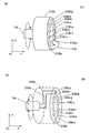
- FIG. 4 is a diagram for explaining the external configuration of the connection switching unit 315.
- the connection switching unit 315 includes a housing 315h for sealing and enclosing a switching unit 315k (not shown in the figure) communicating with the suction pipe 316, and a plurality of units for connecting the suction tubes 312a to 312h and 312z.
- a suction port 315i is provided.
- the housing 315h includes a sealed bearing portion 315j for enabling the switching portion 315k to rotate, so that the switching portion 315k is rotated by a motor (not shown) while maintaining the sealed state inside the housing 315h.
- the plurality of suction ports 315i are provided radially in the outer peripheral direction of the housing 315h so as to correspond to the suction tubes 312a to 312h and the suction tube 312z, respectively.
- the suction port 315ia is connected so as to communicate with the suction tube 312a
- the suction port 315ib is connected so as to communicate with the suction tube 312b
- the suction port 315ih is similarly connected so as to communicate with the suction tube 312h.
- the suction port 315iz is also connected so as to communicate with the suction tube 312z.
- the suction tube 312z is connected not to the inkjet nozzle group 30 but to the ink suction port 315o provided in the housing 315h. Yes.
- the ink suction port 315o is provided for sucking out ink accumulated in the housing 315h when all of the inkjet nozzle group 30 is sucked (described later).
- the ink suction port 315o is preferably provided in a lower position of the housing 315h as a suitable position for sucking out the accumulated ink, and in the Y-axis minus direction when the direction is expressed by the XYZ axes.
- the housing 315h can be realized by stainless steel, titanium, or a fluororesin, which is a material that can withstand the pressure when sucked by the suction pump 314 and is not corroded by ink.
- FIG. 5 is a diagram for explaining the internal configuration of the connection switching unit 315. Inside the connection switching unit 315, a switching unit 315k communicating with the suction pipe 316 is rotatably provided.
- the switching unit 315k has a substantially L-shaped shape, and slides on a plurality of suction ports 315i formed inside the housing 315h by being rotated by a motor (not shown) based on the control of the control unit 1.
- a motor not shown
- the suction tube 312 and the suction conduit 316 communicate with each other, so that the suction pump 314 can suck ink from the inkjet nozzle group 30 covered with the suction cap 311. .
- the sliding portion between the switching unit 315k and the suction port 315i has a sealing structure such as a grease seal, a rubber seal, or a metal seal for efficient suction and for suction of all the inkjet nozzle groups 30 described later. It is desirable to have it.
- the plurality of suction ports 315ia to 315ih are connected so as to be able to communicate with the suction tubes 312a to 312h.
- the suction tube 312z connected to the suction port 315iz is, as illustrated, the ink provided in the lower portion of the housing 315h. It connects so that it can communicate with the suction port 315o.
- the suction portion 315k is slid onto the suction port 315iz and the suction tube 312z and the suction conduit 316 communicate with each other, whereby the suction inside the housing 315h is performed by the suction pump 314.
- FIG. 6 is a diagram for explaining the suction of the inkjet nozzle group 30 by the operation of the connection switching unit 315.
- FIG. 6A is a diagram for explaining an internal state of the housing 315h for explaining a case where the inkjet heads 30a to 30h are individually sucked as a cleaning process for the inkjet nozzle group 30 by the cleaning unit 31.
- the connection switching unit 315 performs an operation for sucking ink of the inkjet head 30a.
- the switching unit 315k When the switching unit 315k is rotated as a result of the rotation of the switching unit 315k as shown in the figure by the control of the control unit 1 in the state shown in FIG. 3, the suction tube 312a and the suction conduit 316 are brought into contact with each other. Will be in communication.
- the electromagnetic on-off valve 313 when the electromagnetic on-off valve 313 is set to “open” and the suction pump 314 starts suction, the sliding portion is sealed, so that the suction line 316 becomes negative pressure.
- Ink flows out from the inkjet head 30a covered with the suction cap 311a through the suction tube 312a communicating with the H.316.
- the ink that has flowed out is sucked by the suction pump 314 via the suction cap 311a and the suction tube 312a, and accumulated in a waste liquid tank (not shown) of the inkjet printing apparatus 100.
- the control unit 1 rotates the switching unit 315k and slides it to the suction ports 315ib to 315ih to open the electromagnetic on-off valve 313, and suction by the suction pump 314 is performed. By doing so, the ink can be sucked from the inkjet heads 30b to 30h, respectively, in the same manner as the inkjet head 30a.
- the ink suction operation shown in FIG. 6A is suitable for cleaning when the cleaning unit 31 performs cleaning of the inkjet nozzle group 30, especially when an abnormality has occurred in each of the inkjet heads 30a to 30h.
- ink suction as shown in FIG. 6 (a) when ink suction as shown in FIG. 6 (a) is performed, it takes time for the inside of the suction cap 311 to return to atmospheric pressure in order to prevent unnecessary ink discharge due to negative pressure. If this time is applied to one ink jet head for about 10 seconds, if the number of ink jet heads is 8, an idle time of 80 seconds will occur in the cleaning operation.
- the housing 315h of the cleaning unit 31 includes an ink suction port 315o for performing suction inside the housing 315h.
- FIG. 6B is a diagram for explaining an internal state of the housing 315h for explaining a case where the inkjet heads 30a to 30h are collectively sucked as a cleaning process for the inkjet nozzle group 30 by the cleaning unit 31.
- the connection switching unit 315 performs an operation for sucking ink from all the inkjet nozzle groups 30.
- the ink suction port 315o can be communicated.
- the suction tube 312z connected to the suction pipe 316 is in communication with the suction conduit 316.
- the electromagnetic on-off valve 313 is “opened” and the suction pump 314 starts suction, since the sliding portion is sealed, the suction line 316 becomes negative pressure, and the housing 315h via the ink suction port 315o.
- the interior also shows negative pressure.
- the housing 315h has a hermetically sealed structure, negative pressure is also applied to the suction caps 311a to 311h via the suction tubes 312a to 312h connected to the suction ports 315ia to 315ih due to the negative pressure inside the housing 315h. Therefore, ink flows out from the inkjet heads 30a to 30h.
- the ink that has flowed out of the inkjet heads 30a to 30h flows into the housing 315h via the suction caps 311a to 311h, the suction tubes 312a to 312h, and the suction ports 315ia to 315ih.
- the ink that has flowed into the housing 315h flows to the suction port 315iz through the ink suction port 315o.
- the ink suction port 315o is provided in the lower part of the housing 315h, the ink accumulated in the housing 315h naturally concentrates on the ink suction port 315o, so that efficient ink suction can be performed.
- the ink is sucked by the suction pump 314 from the ink suction port 315o through the suction tube 312z, and further through the switching unit 315k that is slidably engaged with the suction port 315iz. Accumulated.
- the cleaning unit 31 shown in FIG. 2 includes the connection switching unit 315 as shown in FIGS. 4 and 5, so that the switching unit 315k becomes the suction ports 315ia to 315ih. Is connected to any one of the inkjet heads 30a to 30h, and when the switching unit 315k is connected to the suction port 315iz, the interior of the housing 315h is passed through the ink suction port 315o. Since the ink is sucked from all of the inkjet nozzle groups 30 by suction, it is possible to reduce ink consumption by sucking and purging an inkjet head that does not require suction purge, and it is selective to a plurality of inkjet heads. It is possible to perform a quick cleaning It made.
- the housing 315h of the connection switching unit 315 has been described as having a substantially cylindrical shape and provided with a plurality of suction ports 315i in the outer peripheral direction, but the plurality of suction ports 315i in the housing 315h.
- the arrangement of is not limited to this.
- FIG. 7 is a diagram for explaining another form of the connection switching unit 315.
- the plurality of suction ports 3150i are not in the outer peripheral direction of the housing 3150h but in a co-axial shape parallel to the central axis of the substantially cylinder. It is provided on the opposite side. Even in this case, the ink suction port 3150o can be provided in the lower part of the housing 3150h.
- FIG. 7B is a diagram showing the connection switching unit 315 from the suction pipe line 316 side.
- the disk on the suction pipe 316 side of the housing 3150h and the outer peripheral surface are indicated by broken lines for the sake of explanation.
- the switching unit 3150 k in FIG. 7B has a substantially crank shape, and the switching unit 3150 k is also in communication with the suction pipe 316. Based on the control, it rotates by a motor (not shown) to slide into a plurality of suction ports 3150i formed in the housing 3150h.
- the sliding portion between the switching unit 3150k and the suction port 3150i has a sealing structure such as a grease seal, a rubber seal, or a metal seal for efficient suction and for suction of the entire inkjet nozzle group 30. Is still desirable.
- connection switching unit 315 shown in FIG. 7 can reduce the storage space in the Y-axis direction because the suction conduit 316 and the plurality of suction ports 3150i are arranged substantially coaxially. In addition, it is possible to reduce ink consumption by sucking and purging an inkjet head that does not require suction purge, and it is possible to selectively perform rapid cleaning on a plurality of inkjet heads.
- the housing 315h or 3150h of the connection switching unit 315 includes the ink suction port 315o or 3150o, and the suction tube 312z and the suction port that are connected to the ink suction port 315o or 3150o so as to communicate with each other.
- a suction path that realizes the same function as the suction tube 312z may be formed in the housing 315h or 3150h itself.
- FIG. 8 shows the housing 315′k of the connection switching unit 315 ′.
- the housing 315′h is provided with a plurality of suction ports 315′i including suction ports 315′ia to 315′ih in the suction tubes 312a to 312h, but the ink suction ports 315′o and the suction ports 315′iz
- the suction passage 315′v formed in the housing 315′h communicates with each other.
- in the ink jet printing apparatus 100 it is possible to reduce ink consumption by sucking and purging an ink jet head that does not require suction purging, and selectively with respect to a plurality of ink jet heads. Rapid cleaning can be performed.
- the housing 315h of the connection switching unit 315 has been described as being substantially cylindrical, but the shape of the housing 315h is substantially conical, substantially spherical, or substantially spherical. Also good. That is, the housing 315h may have a shape in which the plurality of suction ports 315i are disposed at an equal distance from the rotation center of the switching unit 315k. Even in this case, the same effects as described above can be achieved.
- connection switching unit 315 is arranged in the cleaning unit 31 so that the rotation center of the switching unit 315k is substantially horizontal.
- the rotation center of the switching unit 315k is approximately vertical.
- the connection switching unit 315 may be arranged so as to be in the direction.
- the ink suction port 315o is provided at the lower part of the housing 315h, the ink is further accumulated by the natural flow, so that the ink suction process of all the inkjet nozzle groups 30 can be performed more efficiently.
- the housing 315h has a substantially conical shape or a substantially spherical crown shape, further efficiency improvement is realized.
- the ink solvent to be cleaned by being used in the inkjet printing apparatus 100 is not limited to water.
- the ink to be cleaned by being used in the ink jet printing apparatus 100 may be not only a dye ink used for general ink jet printing but also a pigment ink.
- the ink to be cleaned by being used in the inkjet printing apparatus 100 is not only an ink used for general printing, but also functions such as circuit pattern formation, biological tissue formation, and three-dimensional modeling. Ink may be used.
- the present invention is suitable for an inkjet printing apparatus.
Landscapes
- Ink Jet (AREA)
- Engineering & Computer Science (AREA)
- Environmental & Geological Engineering (AREA)
Abstract
本発明のインクジェット印刷装置は、複数の管路と接続可能な複数の外部吸引口、およびハウジング内部を吸引する吸引路と接続する内部吸引口が、切換部の回転中心から等しい距離に配設されたハウジングにおいて、該切換部を回転することで複数の外部吸引口のいずれかを選択的に吸引手段に接続する接続切換手段を備えている。したがって、切換部が内部吸引口と接続された場合には、ハウジング内部を吸引することで全てのインクジェットノズルからインクを吸引する。
Description
本発明は、複数のインクジェットヘッドを備えるインクジェット印刷装置に関する。
従来より、多数のインクジェットノズルを有するインクジェットヘッドを備えるインクジェット印刷装置では、インクジェットノズルの一部が目詰まりを起こすことによる、いわゆるノズル欠けと呼称される印刷不良を解消するために、吸引によるインクジェットヘッドのクリーニング(吸引パージ)が行われている。
例えば、特許文献1に記載のインクジェット記録装置は、吐出口群(インクジェットヘッド)を個別に覆うキャップと、インクの吐出口(インクジェットノズル)から吸引によりキャップ内にインクを引き出すためのポンプとを備え、個々のキャップとポンプを接続する接続路に、個別に開閉弁が介設された構成を有している。そして、このインクジェット記録装置では、吐出口群(インクジェットヘッド)の各キャップに連通する接続路に介設された開閉弁を選択的に開放することにより、例えば、インクが吐出されないインクジェットノズルが含まれるインクジェットヘッドを覆うキャップのみを、ポンプと接続して個別吸引する吸引パージが可能となっている。
また、複数のインクジェットヘッドに対してまとめて吸引を行う全体吸引と、1個のインクジェットヘッドに対してのみ個別吸引とを行うことが可能なクリーニング機構を備えるインクジェット印刷装置も提案されている(特許文献2参照)。このクリーニング機構は、複数のインクジェットヘッドを個別に覆うキャップのうちの1個のみがチューブを介してポンプに接続される個別吸引用キャップと、その他複数のキャップに分岐して接続されるチューブを介してポンプに接続されるキャップと、複数のキャップの吸引動作を同時に切り換える第1の開閉弁と、個別吸引用キャップの吸引動作のみを切り換える第2の開閉弁とから構成されている。そして、全体吸引を行う場合には、複数のインクジェットヘッドを全てキャップで覆い、第1、第2の開閉弁を開放して吸引を行っている。また、個別吸引を行う場合には、1個のインクジェットヘッドのみを個別吸引用のキャップで覆い、第1の開閉弁を閉じるとともに第2の開閉弁を開放することで、吸引を行いたいインクジェットヘッドの個別吸引を可能としている。
しかしながら、特許文献1に記載の装置では、電磁開閉弁をキャップの数に応じて多数配設する必要があるため、装置が大型化し生産コストが高くなるという問題が生じる。また、多数の電磁開閉弁を駆動させるため、消費電力が高くなりランニングコストが高くなるという問題も生じる。
一方、特許文献2に記載の装置では、複数のインクジェットヘッドが一方向に列設されたインクジェットユニット毎にクリーニング動作を行っている。このため、インクジェットヘッドの個別吸引を行う場合に、吸引を行う必要があるインクジェットヘッドのインクジェットユニットでの配置によっては、インクジェットヘッドと個別吸引用キャップとの位置あわせのためにインクジェットユニットを移動させる時間が長くなり、インクジェットヘッドのクリーニングに要する時間が長くなるという問題が生じる。
そこで、本発明は、上記課題を解決するために、簡易な構成でありながら、インクの消費を低減することができるとともに、速やかにインクジェットヘッドをクリーニングすることが可能なインクジェット印刷装置を提供することを目的とする。
本発明は、このような目的を達成するために、次のような構成をとる。
すなわち、本発明は、複数のインクジェットノズルが列設された複数のインクジェットヘッドと、前記複数のインクジェットヘッドの各々に対応する複数のキャップと、前記複数のキャップに各々連通接続される複数の管路と、前記複数のキャップおよび複数の管路を介して前記複数のインクジェットノズルからインクを吸引するための吸引手段と、を備えるインクジェット印刷装置であって、前記吸引手段に接続される吸出口と、内部に前記吸出口と連通する連通路が形成されるとともに、駆動手段に接続されることにより回転可能に支持された切換部と、前記切換部を内包するハウジングであって、前記複数の管路と接続可能な複数の外部吸引口、および前記ハウジング内部を吸引する吸引路と接続する内部吸引口が、前記切換部の回転中心から等しい距離に配設されたハウジングと、を備え、前記切換部を前記連通路が前記複数の外部吸引口のいずれかと連通接続する位置に回転させることにより、前記吸引口を前記吸引手段に選択的に接続する接続切換手段と、を有することを特徴とするものである。
すなわち、本発明は、複数のインクジェットノズルが列設された複数のインクジェットヘッドと、前記複数のインクジェットヘッドの各々に対応する複数のキャップと、前記複数のキャップに各々連通接続される複数の管路と、前記複数のキャップおよび複数の管路を介して前記複数のインクジェットノズルからインクを吸引するための吸引手段と、を備えるインクジェット印刷装置であって、前記吸引手段に接続される吸出口と、内部に前記吸出口と連通する連通路が形成されるとともに、駆動手段に接続されることにより回転可能に支持された切換部と、前記切換部を内包するハウジングであって、前記複数の管路と接続可能な複数の外部吸引口、および前記ハウジング内部を吸引する吸引路と接続する内部吸引口が、前記切換部の回転中心から等しい距離に配設されたハウジングと、を備え、前記切換部を前記連通路が前記複数の外部吸引口のいずれかと連通接続する位置に回転させることにより、前記吸引口を前記吸引手段に選択的に接続する接続切換手段と、を有することを特徴とするものである。
本発明によれば、複数の管路と接続可能な複数の外部吸引口、およびハウジング内部を吸引する吸引路と接続する内部吸引口が、切換部の回転中心から等しい距離に配設されたハウジングにおいて、該切換部を回転することで複数の外部吸引口のいずれかを選択的に吸引手段に接続する接続切換手段を備えている。したがって、切換部が外部吸引口のいずれかと接続された場合には複数のインクジェットノズルのうちいずれかからインクを吸引し、切換部が内部吸引口と接続された場合には、ハウジング内部を吸引することにより全てのインクジェットノズルからインクを吸引するので、吸引パージの必要のないインクジェットヘッドを吸引パージすることによるインクの消費を低減することができる。さらに、複数のインクジェットヘッドに対して選択的に迅速なクリーニングを実行することが可能となる。
また、本発明において、前記ハウジングは、該ハウジング内部を吸引する吸引路の吸出口を下部に備えることが好ましい。
また、本発明において、前記ハウジングは、前記複数の外部吸引口をラジアル状に備えることが好ましい。
また、本発明において、前記ハウジングは、前記複数の外部吸引口をコ-アキシャル状に備えることが好ましい。
また、本発明において、前記ハウジングに、該ハウジング内部を吸引する吸引路が形成されていることが好ましい。
また、本発明において、前記切換部は、L字型形状を呈し、前記駆動手段により一端側が回転され、他端側が前記複数の外部吸引口のそれぞれに連通接続されることが好ましい。
また、本発明において、前記切換部は、クランク形状を呈し、前記駆動手段により一端側が回転され、他端側が前記複数の外部吸引口のそれぞれに連通接続されることが好ましい。
また、本発明において、前記ハウジングは、前記切換部の回転中心に密閉軸受け部を備えていることが好ましい。
また、本発明において、前記複数のインクジェットヘッドは、単一のインク色に対して複数備えられるこが好ましい。
本発明に係るインクジェット印刷装置は、複数の管路と接続可能な複数の外部吸引口、およびハウジング内部を吸引する吸引路と接続する内部吸引口が、切換部の回転中心から等しい距離に配設されたハウジングにおいて、該切換部を回転することで複数の外部吸引口のいずれかを選択的に吸引手段に接続する接続切換手段を備えている。したがって、切換部が外部吸引口のいずれかと接続された場合には複数のインクジェットノズルのうちいずれかからインクを吸引し、切換部が内部吸引口と接続された場合には、ハウジング内部を吸引することにより全てのインクジェットノズルからインクを吸引するので、吸引パージの必要のないインクジェットヘッドを吸引パージすることによるインクの消費を低減することができる。さらに、複数のインクジェットヘッドに対して選択的に迅速なクリーニングを実行することが可能となる。
また、ハウジング下部に該ハウジング内部を吸引する吸引路の吸出口を備えるので、ハウジング内部に蓄積したインクを確実に吸引することができる。
さらに、ハウジング内部を吸引する吸引路が形成されたハウジングなので、ハウジングをコンパクトにすることができる。
以下、図面を利用しながら、本発明を実施形態について、説明を行なう。
〈第1の実施形態〉
図1は、本発明に係るインクジェット印刷装置100を説明するための図である。インクジェット印刷装置100は、搬送されるロール紙に対してインクを吐出して印刷を行なう印刷装置である。インクジェット印刷装置100は、制御部1、搬送部2、吐出部3、乾燥部4、検査部5を備える。
図1は、本発明に係るインクジェット印刷装置100を説明するための図である。インクジェット印刷装置100は、搬送されるロール紙に対してインクを吐出して印刷を行なう印刷装置である。インクジェット印刷装置100は、制御部1、搬送部2、吐出部3、乾燥部4、検査部5を備える。
制御部1は、インクジェット印刷装置100全体を制御するためのものである。制御部1が、搬送部2による用紙9の搬送、吐出部3による用紙9へのインク吐出、あるいは吐出部3におけるクリーニング動作、乾燥部4におけるインクが吐出された用紙9の乾燥、検査部5における用紙9の印刷像撮影をそれぞれ制御することにより、用紙9に対するインクジェット印刷装置100の印刷を実現している。
搬送部2は、インクジェット印刷装置100における用紙9の搬送を行なうための構成であり、用紙収納部20、駆動ローラ21、支持ローラ22を備えている。
用紙収納部20は、印刷を行なうためのロール紙である用紙9を収納するためのものであり、用紙収納部20aは印刷前の用紙9を収納し、用紙収納部20bは印刷後の用紙9を収納する。
用紙収納部20aから引き出された用紙9は、支持ローラ22によって支持されながら駆動ローラ21a、21bによって吐出部3、乾燥部4、検査部5を搬送され、用紙収納部20bに巻取られる。
吐出部3は、図示しないインクタンクからインクの供給を受け、制御部1が画像情報に基づいて生成した駆動信号によってインクを吐出し、用紙9に対する印刷を行なう。
吐出部3は複数のインクジェットノズル群30k、30c、30m、30yを備えている。インクジェットノズル群30k、30c、30m、30yは用紙9の搬送方向に直交しており、多数のノズルを列設することにより用紙9の搬送幅以上の吐出幅を実現している。吐出部3がこのような構成を備えることにより、吐出部3は用紙9の搬送幅方向に往復走査せずとも一度の吐出で印刷を実行する。
なお、吐出部3のインクジェットノズル群の数は4つに限定されることはなく、単色吐出のためインクジェットノズル群の数は1つであってもよいし、特色を加えた吐出を行なうため5つ以上のインクジェットノズル群を備えていても良い。
乾燥部4は、ヒーター、ドライヤー等により、吐出部3による印刷後の用紙9に対して熱を加えることにより、インクの溶媒(主に水である)を蒸発させることで、インクの定着を行なう。
なお、吐出部3による吐出がUV硬化インクなどの放射線硬化インクである場合、乾燥部4は放射線発振を行なうための構成を備えることで、用紙9に対するインクの定着(硬化)を行なうことになる。
なお、吐出部3による吐出がUV硬化インクなどの放射線硬化インクである場合、乾燥部4は放射線発振を行なうための構成を備えることで、用紙9に対するインクの定着(硬化)を行なうことになる。
検査部5は、制御部1が用紙9に行なわれた印刷が良好であるか否かを判定するために、印刷像を撮影する。検査部5は、CCDラインセンサ、あるいはCCDカメラにより、搬送される用紙9に印刷された印刷像を撮影し、制御部1へ撮影情報を送信する。制御部1は、インク吐出を行なうために使用した画像情報と撮影情報とを比較することにより、吐出部3における吐出不良の有無を判定することによって、印刷が良好であるか否かを判定することができる。
吐出不良とは、ノズルからのインク不吐出、インク滴の不良飛翔、インク滴サイズの不良等であり、このような吐出部3における吐出不良が存在すると制御部1が判断したならば、制御部1は吐出部3のクリーニングを実行する。
図2、および図3は、クリーニングを実行する吐出部3の概要を説明するための図である。図2は、吐出部3が用紙9に対する印刷を行なっている状態であり、図3は吐出部3がクリーニングを行っている状態である。
吐出部3は、インクジェットノズル群30のクリーニングを行なうため、吸引キャップ311、吸引チューブ312、電磁開閉弁313、吸引ポンプ314、接続切換部315、吸引管路316と、を有するクリーニング部31を備えている。
なお、ここでは、一つのインクジェットノズル群30を構成するために、8個のインクジェットヘッド30a~30hが列設されているものとして説明を行なう。無論、インクジェットノズル群30を構成するために列設されるインクジェットヘッドの数は、8個に限定されることはない。
また、ここでは、説明のため一つのインクジェットノズル群30に対応する一つのクリーニング部31を備えているよう説明しているが、複数のインクジェットノズル群30各々に対応した複数のクリーニング部31を吐出部3が備えている。
吸引キャップ311は、ノズルの乾燥、汚染を防ぐため、インクジェットノズル群30を被覆する。吸引ポンプ314に接続される吸引チューブ312を備えた吸引キャップ311は、制御部1の制御に基づいてインクジェットノズル群30が下降することで、図3に示すような被覆を実行し、インクジェットノズル群30のインク詰まりを解消するための吸引を行なうことができる。
ここでは、インクジェットヘッド30a~30hに対応して、吸引キャップ311a~311hが備えられている。
吸引チューブ312は、前述のように吸引キャップ311に接続されており、図3に示すように吸引キャップ311に被覆されたインクジェットノズル群30から吸引されたインクは吸引チューブ312を経て吸引ポンプ314によって吸引される。
ここでは、吸引キャップ311a~311hに対応して、吸引チューブ312a~312hが備えられており、接続切換部315に吸引可能に接続されている。
また、吸引チューブ312zは、吸引キャップ311に直接接続はされていないが、接続切換部315内部の吸引を行なうように接続切換部315に接続されることで、吸引キャップ311a~311hからのインク吸引を実現する(詳細は後述する)。
電磁開閉弁313は、吸引ポンプ314と接続切換部315とを接続する接続する吸引管路316に備えられている。制御部1の制御により、電磁開閉弁313は、図2に示すようにインクジェットノズル群30による用紙9への吐出処理が行なわれている間は吸引管路316を閉鎖している。図3に示すように、インクジェットノズル群30を吸引キャップ311が被覆し、接続切換部315が吸引ポンプ314と吸引チューブ312a~312hとをそれぞれ切り換えて接続することでインクジェットヘッド30a~30hからインクの吸引を行なう時、制御部1の制御により電磁開閉弁313が吸引管路316を開放する(詳細は後述する)。
また、接続切換部315が吸引チューブ312zに切り換えて接続することで、吸引ポンプ314がインクジェットヘッド30a~30hからまとめてインクを吸引する場合にも、電磁開閉弁313は制御部1の制御により、吸引管路316を開放する(詳細は後述する)。
吸引ポンプ314は、図3に示すような状態で、吸引管路316、接続切換部315、吸引チューブ312a~312h、あるいは312z、吸引キャップ311を介して、インクジェットノズル群30からインクを吸引する。吸引ポンプ314が負圧を発生させると、インクジェットノズル群30からインクが流出する。負圧によって流出したインクは、吸引キャップ311、吸引チューブ312、接続切換部315、吸引管路316、吸引ポンプ314を経由して、インクジェット印刷装置100の図示しない廃液タンクに蓄積される。
接続切換部315は、吸引ポンプ314によるインクジェットノズル群30のインク吸引を行なうに際して、インクジェットノズル群30を構成するインクジェットヘッド30a~30hを個別に吸引するため、あるいはインクジェットヘッド30a~30hまとめて吸引するために、制御部1の制御に基づいて、吸引管路316と吸引チューブ312a~h、あるいは312zとを切り換える。
接続切換部315の詳細について図4および図5を参照しながら説明する。
図4は、接続切換部315の外部構成を説明するための図である。接続切換部315は、吸引管路316に連通する切換部315k(本図では図示せず)を密閉して内包するためのハウジング315hが、吸引チューブ312a~312h、312zを接続するための複数の吸引口315iを備えている。
ハウジング315hは、切換部315kを回転可能とするための密閉軸受け部315jを備えることにより、ハウジング315h内部の密閉状態を維持したまま、切換部315kの回転が図示しないモータによって行なわれる。
複数の吸引口315iは、それぞれ吸引チューブ312a~312h、および吸引チューブ312zに対応するように、ハウジング315hの外周方向にラジアル状に備えられている。
すなわち、吸引口315iaが吸引チューブ312aに連通するように接続され、吸引口315ibが吸引チューブ312bに連通するように接続され、以降同様に吸引口315ihが吸引チューブ312hに連通するように接続されている。
一方、吸引口315izもまた吸引チューブ312zに連通するように接続されているが、吸引チューブ312zはインクジェットノズル群30ではなく、ハウジング315hに備えられたインク吸出口315oに連通するように接続されている。
インク吸出口315oは、インクジェットノズル群30全ての吸引を行なった際(後述する)に、ハウジング315h内に蓄積されるインクを吸い出すために備えられたものである。インク吸出口315oは、蓄積したインクを吸い出すのに好適な位置として、ハウジング315h下部、XYZ軸で方向を表現する場合はY軸マイナス方向、に備えられることが望ましい。
ハウジング315hは、吸引ポンプ314による吸引時の圧力に耐え、かつインクによって腐食されない材質であるステンレスやチタニウム、あるいはフッ素樹脂などで実現することができる。
図5は、接続切換部315の内部構成を説明するための図である。接続切換部315の内部には、吸引管路316に連通する切換部315kが回転可能に備えられている。
切換部315kは略L字型の形状を有しており、制御部1の制御に基づいて、図示しないモータによって回転することでハウジング315h内部に形成された複数の吸引口315iに滑合する。切換部315kと吸引口315iが滑合すると、吸引チューブ312と吸引管路316が連通するので、吸引ポンプ314が吸引キャップ311に被覆されたインクジェットノズル群30からインクを吸引することが可能となる。
なお、切換部315kと吸引口315iとの滑合部位は、効率のよい吸引を行なうため、また後述するインクジェットノズル群30全ての吸引のため、グリスシールやゴムシール、あるいはメタルシールなどのシーリング構造を備えていることが望ましい。
複数の吸引口315ia~315ihは、吸引チューブ312a~312hに連通可能なように接続されているが、吸引口315izに接続された吸引チューブ312zは、図示するようにハウジング315h下部に備えられたインク吸出口315oに連通可能なように接続されている。このような接続がなされていることにより、切換部315kを吸引口315izに滑合させて吸引チューブ312zと吸引管路316が連通することにより、吸引ポンプ314によってハウジング315h内部の吸引が行なわれる。
図6は、接続切換部315の動作によるインクジェットノズル群30の吸引を説明するための図である。
図6(a)は、クリーニング部31によるインクジェットノズル群30に対するクリーニング処理として、インクジェットヘッド30a~30hを個別に吸引する場合を説明するためのハウジング315hの内部状態を説明するための図であり、ここでは接続切換部315は、インクジェットヘッド30aのインクを吸引するための動作を実行している。
吐出部3が図3に示すような状態で、制御部1の制御により、図示しているように切換部315kが回転の結果、吸引口315iaと滑合すると、吸引チューブ312aと吸引管路316が連通した状態となる。ここで、電磁開閉弁313を「開」として、吸引ポンプ314が吸引を開始することにより、滑合部分がシーリングされていることから吸引管路316が負圧となり、該負圧によって吸引管路316と連通する吸引チューブ312aを経て吸引キャップ311aに被覆されたインクジェットヘッド30aからインクが流出する。流出したインクは、吸引キャップ311a、吸引チューブ312aを経由して、吸引ポンプ314により吸引され、インクジェット印刷装置100の図示しない廃液タンクに蓄積される。
インクジェットヘッド30b~30hから、それぞれインクを吸引する場合は、制御部1が切換部315kを回転させ、吸引口315ib~315ihにそれぞれ滑合させて電磁開閉弁313を開き、吸引ポンプ314による吸引を行なうことにより、インクジェットヘッド30a同様に、インクジェットヘッド30b~30hからそれぞれインクを吸引することができる。
図6(a)に示すインク吸引動作は、クリーニング部31がインクジェットノズル群30のクリーニングを行なうに際して、特に個々のインクジェットヘッド30a~30hに異常が生じていた場合のクリーニングとして好適なものである。
しかし、インクジェットノズル群30を構成するインクジェットヘッドの数が多い場合には、全てのインクジェットヘッドからインクを吸引するために図6(a)に示すような動作を繰り返し行なうことは多大な時間を要することになる。
例えば、図6(a)に示すようなインク吸引を行なった場合、負圧による余計なインク吐出を防止するためには、吸引キャップ311内が大気圧に戻るまでの時間を必要とする。この時間を一つのインクジェットヘッドに10秒ほどかけるとすると、インクジェットヘッドの数が8個ならば、クリーニング動作において80秒ものアイドルタイムが生じることになる。
そのような問題を解決するため、クリーニング部31のハウジング315hは、該ハウジング315h内部の吸引を行なうためのインク吸引口315oを備えている。
図6(b)は、クリーニング部31によるインクジェットノズル群30に対するクリーニング処理として、インクジェットヘッド30a~30hをまとめて吸引する場合を説明するためのハウジング315hの内部状態を説明するための図である。ここでは接続切換部315は、インクジェットノズル群30全てからインクを吸引するための動作を実行している。
吐出部3が図3に示すような状態で、制御部1の制御に基づいて、図示しているように切換部315kが回転の結果吸引口315izと滑合すると、インク吸出口315oと連通可能に接続した吸引チューブ312zと吸引管路316が連通した状態となる。ここで、電磁開閉弁313を「開」として、吸引ポンプ314が吸引を開始すると、滑合部分がシーリングされていることから吸引管路316が負圧となり、インク吸出口315oを介したハウジング315h内部もまた負圧を示す。
ハウジング315hは密閉構造を有しているので、ハウジング315h内部が負圧となることにより、吸引口315ia~315ihに接続された吸引チューブ312a~312hを経て吸引キャップ311a~311hにも負圧が加わるため、インクジェットヘッド30a~30hからインクが流出する。
インクジェットヘッド30a~30hから流出したインクは、吸引キャップ311a~311h、吸引チューブ312a~312h、吸引口315ia~315ihを経由して、ハウジング315h内部に流れ込む。
ハウジング315h内部に流れ込んだインクは、インク吸出口315oを経て吸引口315izに流れる。ここで、インク吸出口315oがハウジング315hの下部に備えられているので、ハウジング315h内部に蓄積されたインクが自然にインク吸出口315oに集中するため、効率のよいインク吸引を行なうことができる。
そして、インク吸出口315oから吸引チューブ312zを経て、さらに吸引口315izと滑合した切換部315kを経由して吸引ポンプ314によりインクが吸引されることで、インクジェット印刷装置100の図示しない廃液タンクに蓄積される。
従って、図6(b)に示すインク吸引動作は、クリーニング部31がインクジェットノズル群30のクリーニングを行なうに際して、短時間で全てのインクジェットヘッド30a~30hのクリーニングを実現することができる。
このように、図1に示したインクジェット印刷装置100において、図2に示したクリーニング部31が図4、5に示すような接続切換部315を備えることにより、切換部315kが吸引口315ia~315ihのいずれかと接続された場合にはインクジェットヘッド30a~30hのうちいずれかからインクを吸引し、切換部315kが吸引口315izと接続された場合には、インク吸出口315oを介してハウジング315h内部を吸引することによりインクジェットノズル群30全てからインクを吸引するので、吸引パージの必要のないインクジェットヘッドを吸引パージすることによるインクの消費を低減することができるとともに、複数のインクジェットヘッドに対して選択的に迅速なクリーニングを実行することが可能となる。
また、インクジェットノズル群30からのインク吸引のみならず、該インクジェットノズル群30に対して制御部1が行なわせたフラッシング処理、あるいは加圧パージ処理により、吸引キャップ311a~311hに蓄積したインクの吸引に際しても図6(b)に示すインク吸引動作を実行することにより、吸引キャップ311からインクが溢れるのを防止することができる。
〈第2の実施形態〉
ここまでの説明では、接続切換部315のハウジング315hについて、略円筒形状を有しており外周方向に複数の吸引口315iを備えるものとして説明を行なってきたが、ハウジング315hにおける複数の吸引口315iの配置は、これに限定されることはない。
ここまでの説明では、接続切換部315のハウジング315hについて、略円筒形状を有しており外周方向に複数の吸引口315iを備えるものとして説明を行なってきたが、ハウジング315hにおける複数の吸引口315iの配置は、これに限定されることはない。
図7は、接続切換部315の別の形態を説明するための図である。
図7(a)に示す接続切換部315のハウジング3150hにおいて、複数の吸引口3150iは、該ハウジング3150hの外周方向ではなく、略円筒の中心軸に平行するコ-アキシャル状に、吸引管路316の反対側に設けられている。この場合でも、インク吸出口3150oは、ハウジング3150hの下部に設けるようにすることができる。
図7(b)は、吸引管路316側から接続切換部315を示した図である。ここで、ハウジング3150hの吸引管路316側の円板、および外周面は説明のため破線で示している。
図7(b)の切換部3150kは、図5に示したものとは異なり、略クランク形状を有している、切換部3150kもまた、吸引管路316に連通しており、制御部1の制御に基づいて、図示しないモータによって回転することでハウジング3150h内部に形成された複数の吸引口3150iに滑合する。
切換部3150kと吸引口3150iとの滑合部位は、効率のよい吸引を行なうため、またインクジェットノズル群30全ての吸引のため、グリスシールやゴムシール、あるいはメタルシールなどのシーリング構造を備えていることがやはり望ましい。
図7に示す接続切換部315は、吸引管路316と複数の吸引口3150iが略同軸状に配置されることから、Y軸方向についての収納スペースを削減することができ、インクジェット印刷装置100において、吸引パージの必要のないインクジェットヘッドを吸引パージすることによるインクの消費を低減することができるとともに、複数のインクジェットヘッドに対して選択的に迅速なクリーニングを実行することが可能となる。
〈第3の実施形態〉
ここまでの説明では、接続切換部315のハウジング315h、あるいは3150hがインク吸出口315o、あるいは3150oを備えており、該インク吸出口315o、あるいは3150oに連通可能に接続された吸引チューブ312zと吸引口315iz、あるいは3150izが接続される構成を有するものとして説明を行なってきたが、ハウジング315h、あるいは3150h自体に吸引チューブ312zと同様の機能を実現する吸引路を構成するようにしてもよい。
ここまでの説明では、接続切換部315のハウジング315h、あるいは3150hがインク吸出口315o、あるいは3150oを備えており、該インク吸出口315o、あるいは3150oに連通可能に接続された吸引チューブ312zと吸引口315iz、あるいは3150izが接続される構成を有するものとして説明を行なってきたが、ハウジング315h、あるいは3150h自体に吸引チューブ312zと同様の機能を実現する吸引路を構成するようにしてもよい。
図8は、接続切換部315'のハウジング315'kである。ハウジング315'hは、吸引チューブ312a~312hに吸引口315'ia~315'ihからなる複数の吸引口315'iを備えているが、インク吸出口315'oと吸引口315'izとの間を連通しているのは、ハウジング315'hに形成された吸引路315'vである。
このような構成であっても、インクジェット印刷装置100において、吸引パージの必要のないインクジェットヘッドを吸引パージすることによるインクの消費を低減することができるとともに、複数のインクジェットヘッドに対して選択的に迅速なクリーニングを実行することが可能となる。
〈変形例〉
ここまでの説明では、接続切換部315のハウジング315hについて、略円筒状であると説明を行なってきたが、ハウジング315hの形状が略円錐形や略球帯形、あるいは略球冠形であってもよい。すなわち、ハウジング315hは、複数の吸引口315iが切換部315kの回転中心から等しい距離に配設される形状であれば良い。この場合であっても、これまでの説明同様の作用効果を奏することができる。
ここまでの説明では、接続切換部315のハウジング315hについて、略円筒状であると説明を行なってきたが、ハウジング315hの形状が略円錐形や略球帯形、あるいは略球冠形であってもよい。すなわち、ハウジング315hは、複数の吸引口315iが切換部315kの回転中心から等しい距離に配設される形状であれば良い。この場合であっても、これまでの説明同様の作用効果を奏することができる。
また、ここまでの説明では、クリーニング部31において切換部315kの回転中心が略水平方向となるように接続切換部315が配置された状態を説明してきたが、切換部315kの回転中心が略垂直方向となるように接続切換部315が配置される状態であってもよい。
この場合、インク吸出口315oをハウジング315hの下部に備えることにより、自然流下によってさらにインクの蓄積が行なわれるので、インクジェットノズル群30全てのインク吸引処理をより効率的に行なうことができる。特に、ハウジング315hが略円錐形、あるいは略球冠形であれば、さらなる効率化が実現する。
なお、インクジェット印刷装置100で使用されることでクリーニングの対象となるインクの溶媒は、水に限定されることはない。
また、インクジェット印刷装置100で使用されることでクリーニングの対象となるインクは、一般的なインクジェット印刷に使用される染料インクのみならず顔料インクであってもよい。
さらに、インクジェット印刷装置100で使用されることでクリーニングの対象となるインクは、一般的な印刷に使用されるインクのみならず回路パターン形成用、生体組織形成用、三次元造形用などの機能性インクであってもよい。
以上のように、本発明は、インクジェット印刷装置に適している。
1 制御部
2 搬送部
3 吐出部
4 乾燥部
5 検査部
9 用紙
30、30k、30c、30m、30y インクジェットノズル群
31 クリーニング部
311、311a、311b、311c、311d、311e、311f、311g、311h 吸引キャップ
312、312a、312b、312c、312d、312e、312f、312g、312h、312z 吸引チューブ
313 電磁開閉弁
314 吸引ポンプ
315 接続切換部
316 吸引管路
315h、315'h 3150h ハウジング
315i、315ia、315ib、315ic、315id、315ie、315if、315ig、315ih、315iz、3150i 吸引口
315k、315'k、3150k 切換部
315j 密閉軸受け部
315o、315'o、3150o インク吸出口
2 搬送部
3 吐出部
4 乾燥部
5 検査部
9 用紙
30、30k、30c、30m、30y インクジェットノズル群
31 クリーニング部
311、311a、311b、311c、311d、311e、311f、311g、311h 吸引キャップ
312、312a、312b、312c、312d、312e、312f、312g、312h、312z 吸引チューブ
313 電磁開閉弁
314 吸引ポンプ
315 接続切換部
316 吸引管路
315h、315'h 3150h ハウジング
315i、315ia、315ib、315ic、315id、315ie、315if、315ig、315ih、315iz、3150i 吸引口
315k、315'k、3150k 切換部
315j 密閉軸受け部
315o、315'o、3150o インク吸出口
Claims (14)
- 複数のインクジェットノズルが列設された複数のインクジェットヘッドと、前記複数のインクジェットヘッドの各々に対応する複数のキャップと、前記複数のキャップに各々連通接続される複数の管路と、前記複数のキャップおよび複数の管路を介して前記複数のインクジェットノズルからインクを吸引するための吸引手段と、を備えるインクジェット印刷装置であって、
前記吸引手段に接続される吸出口と、
内部に前記吸出口と連通する連通路が形成されるとともに、駆動手段に接続されることにより回転可能に支持された切換部と、
前記切換部を内包するハウジングであって、前記複数の管路と接続可能な複数の外部吸引口、および前記ハウジング内部を吸引する吸引路と接続する内部吸引口が、前記切換部の回転中心から等しい距離に配設されたハウジングと、
を備え、
前記切換部を前記連通路が前記複数の外部吸引口のいずれかと連通接続する位置に回転させることにより、前記吸引口を前記吸引手段に選択的に接続する接続切換手段と、
を有することを特徴とするインクジェット印刷装置。 - 請求項1に記載のインクジェット印刷装置において、
前記ハウジングは、該ハウジング内部を吸引する吸引路の吸出口を下部に備えることを特徴とするインクジェット印刷装置。 - 請求項1に記載のインクジェット印刷装置において、
前記ハウジングは、前記複数の外部吸引口をラジアル状に備えることを特徴とするインクジェット印刷装置。 - 請求項1に記載のインクジェット印刷装置において、
前記ハウジングは、前記複数の外部吸引口をコ-アキシャル状に備えることを特徴とするインクジェット印刷装置。 - 請求項1に記載のインクジェット印刷装置において、
前記ハウジングに、該ハウジング内部を吸引する吸引路が形成されていることを特徴とするインクジェット印刷装置。 - 請求項3に記載のインクジェット印刷装置において、
前記切換部は、L字型形状を呈し、前記駆動手段により一端側が回転され、他端側が前記複数の外部吸引口のそれぞれに連通接続されることを特徴とするインクジェット印刷装置。 - 請求項4に記載のインクジェット印刷装置において、
前記切換部は、クランク形状を呈し、前記駆動手段により一端側が回転され、他端側が前記複数の外部吸引口のそれぞれに連通接続されることを特徴とするインクジェット印刷装置。 - 請求項6に記載のインクジェット印刷装置において、
前記ハウジングは、前記切換部の回転中心に密閉軸受け部を備えていることを特徴とするインクジェット印刷装置。 - 請求項7に記載のインクジェット印刷装置において、
前記ハウジングは、前記切換部の回転中心に密閉軸受け部を備えていることを特徴とするインクジェット印刷装置。 - 請求項1に記載のインクジェット印刷装置において、
前記複数のインクジェットヘッドは、単一のインク色に対して複数備えられることを特徴とするインクジェット印刷装置。 - 請求項2に記載のインクジェット印刷装置において、
前記複数のインクジェットヘッドは、単一のインク色に対して複数備えられることを特徴とするインクジェット印刷装置。 - 請求項3に記載のインクジェット印刷装置において、
前記複数のインクジェットヘッドは、単一のインク色に対して複数備えられることを特徴とするインクジェット印刷装置。 - 請求項4のいずれかに記載のインクジェット印刷装置において、
前記複数のインクジェットヘッドは、単一のインク色に対して複数備えられることを特徴とするインクジェット印刷装置。 - 請求項5のいずれかに記載のインクジェット印刷装置において、
前記複数のインクジェットヘッドは、単一のインク色に対して複数備えられることを特徴とするインクジェット印刷装置。
Priority Applications (3)
| Application Number | Priority Date | Filing Date | Title |
|---|---|---|---|
| US14/003,221 US9731510B2 (en) | 2011-03-24 | 2011-09-22 | Inkjet printing apparatus |
| US15/058,038 US20160207314A1 (en) | 2011-03-24 | 2016-03-01 | Inkjet printing apparatus |
| US15/058,041 US20160193839A1 (en) | 2011-03-24 | 2016-03-01 | Inkjet printing apparatus |
Applications Claiming Priority (2)
| Application Number | Priority Date | Filing Date | Title |
|---|---|---|---|
| JP2011065633A JP5700809B2 (ja) | 2011-03-24 | 2011-03-24 | インクジェット印刷装置 |
| JP2011-065633 | 2011-03-24 |
Related Child Applications (3)
| Application Number | Title | Priority Date | Filing Date |
|---|---|---|---|
| US14/003,221 A-371-Of-International US9731510B2 (en) | 2011-03-24 | 2011-09-22 | Inkjet printing apparatus |
| US15/058,038 Division US20160207314A1 (en) | 2011-03-24 | 2016-03-01 | Inkjet printing apparatus |
| US15/058,041 Division US20160193839A1 (en) | 2011-03-24 | 2016-03-01 | Inkjet printing apparatus |
Publications (1)
| Publication Number | Publication Date |
|---|---|
| WO2012127543A1 true WO2012127543A1 (ja) | 2012-09-27 |
Family
ID=46878745
Family Applications (1)
| Application Number | Title | Priority Date | Filing Date |
|---|---|---|---|
| PCT/JP2011/005351 Ceased WO2012127543A1 (ja) | 2011-03-24 | 2011-09-22 | インクジェット印刷装置 |
Country Status (3)
| Country | Link |
|---|---|
| US (3) | US9731510B2 (ja) |
| JP (1) | JP5700809B2 (ja) |
| WO (1) | WO2012127543A1 (ja) |
Families Citing this family (2)
| Publication number | Priority date | Publication date | Assignee | Title |
|---|---|---|---|---|
| JP5895836B2 (ja) * | 2012-12-28 | 2016-03-30 | ブラザー工業株式会社 | 液体吐出装置 |
| JP6011336B2 (ja) * | 2012-12-28 | 2016-10-19 | ブラザー工業株式会社 | 液体吐出装置及びプログラム |
Citations (3)
| Publication number | Priority date | Publication date | Assignee | Title |
|---|---|---|---|---|
| JP2007008156A (ja) * | 2005-05-31 | 2007-01-18 | Brother Ind Ltd | インクジェット記録装置 |
| JP2007111911A (ja) * | 2005-10-18 | 2007-05-10 | Brother Ind Ltd | 画像記録装置 |
| JP2010125746A (ja) * | 2008-11-28 | 2010-06-10 | Mimaki Engineering Co Ltd | インクジェットプリンタ |
Family Cites Families (5)
| Publication number | Priority date | Publication date | Assignee | Title |
|---|---|---|---|---|
| US7556340B2 (en) | 2005-05-31 | 2009-07-07 | Brother Kogyo Kabushiki Kaisha | Ink jet recording apparatus |
| US20090015625A1 (en) | 2005-11-21 | 2009-01-15 | Dainippon Screen Mfg, Co., Ltd. | Printing Apparatus And Cleaning Mechanism Thereof |
| JP2008213216A (ja) | 2007-03-01 | 2008-09-18 | Canon Inc | インクジェット記録装置 |
| JP4784657B2 (ja) * | 2009-02-04 | 2011-10-05 | ブラザー工業株式会社 | 記録装置 |
| JP5364629B2 (ja) * | 2010-03-30 | 2013-12-11 | 大日本スクリーン製造株式会社 | インクジェット印刷装置 |
-
2011
- 2011-03-24 JP JP2011065633A patent/JP5700809B2/ja active Active
- 2011-09-22 US US14/003,221 patent/US9731510B2/en active Active
- 2011-09-22 WO PCT/JP2011/005351 patent/WO2012127543A1/ja not_active Ceased
-
2016
- 2016-03-01 US US15/058,041 patent/US20160193839A1/en not_active Abandoned
- 2016-03-01 US US15/058,038 patent/US20160207314A1/en not_active Abandoned
Patent Citations (3)
| Publication number | Priority date | Publication date | Assignee | Title |
|---|---|---|---|---|
| JP2007008156A (ja) * | 2005-05-31 | 2007-01-18 | Brother Ind Ltd | インクジェット記録装置 |
| JP2007111911A (ja) * | 2005-10-18 | 2007-05-10 | Brother Ind Ltd | 画像記録装置 |
| JP2010125746A (ja) * | 2008-11-28 | 2010-06-10 | Mimaki Engineering Co Ltd | インクジェットプリンタ |
Also Published As
| Publication number | Publication date |
|---|---|
| US20140002541A1 (en) | 2014-01-02 |
| JP5700809B2 (ja) | 2015-04-15 |
| US20160193839A1 (en) | 2016-07-07 |
| US20160207314A1 (en) | 2016-07-21 |
| JP2012200930A (ja) | 2012-10-22 |
| US9731510B2 (en) | 2017-08-15 |
Similar Documents
| Publication | Publication Date | Title |
|---|---|---|
| JP5364629B2 (ja) | インクジェット印刷装置 | |
| US8454120B2 (en) | Liquid ejection device | |
| JP7139885B2 (ja) | 液体噴射装置、液体噴射装置のメンテナンス方法 | |
| CN109278411B (zh) | 液体喷射装置 | |
| JP2013018149A (ja) | 液体吐出装置 | |
| JP2018114660A (ja) | インクジェット記録装置 | |
| CN102848723B (zh) | 液体喷射设备 | |
| JP5700809B2 (ja) | インクジェット印刷装置 | |
| JP5199138B2 (ja) | 液滴吐出装置 | |
| CN205997508U (zh) | 打印头维护站 | |
| JP2016002721A (ja) | 画像形成装置及び液体吐出ヘッド用キャップ | |
| JP2011121295A (ja) | 流体噴射装置 | |
| KR100736593B1 (ko) | 잉크젯 프린터용 다기능 헤드 클리너 | |
| JP6996362B2 (ja) | インクジェット記録装置及びメンテナンス方法 | |
| JP2008246953A (ja) | インクジェット記録装置 | |
| JP2012161923A (ja) | 液体吐出装置 | |
| JP2008246952A (ja) | インクジェット記録装置用メンテナンス方法 | |
| CN107662413B (zh) | 喷墨记录设备和清洁方法 | |
| JP7323029B2 (ja) | 液体噴射装置、液体噴射装置のメンテナンス方法 | |
| JP4645405B2 (ja) | 液体噴射装置の検査装置及び流路切換装置 | |
| JP2012111146A (ja) | インク充填方法、インク置換方法、インク充填補助液体及びインクカートリッジ | |
| JP2002347260A (ja) | 印字機構維持回復装置及びインクジェット記録装置 | |
| JP2014028445A (ja) | 液体吐出装置 | |
| JP2009051122A (ja) | インク吸引機構 | |
| JP2012206394A (ja) | 液体吐出装置 |
Legal Events
| Date | Code | Title | Description |
|---|---|---|---|
| 121 | Ep: the epo has been informed by wipo that ep was designated in this application |
Ref document number: 11861529 Country of ref document: EP Kind code of ref document: A1 |
|
| WWE | Wipo information: entry into national phase |
Ref document number: 14003221 Country of ref document: US |
|
| NENP | Non-entry into the national phase |
Ref country code: DE |
|
| 122 | Ep: pct application non-entry in european phase |
Ref document number: 11861529 Country of ref document: EP Kind code of ref document: A1 |