WO2012124762A1 - ポリスルホンペレットの製造方法 - Google Patents
ポリスルホンペレットの製造方法 Download PDFInfo
- Publication number
- WO2012124762A1 WO2012124762A1 PCT/JP2012/056675 JP2012056675W WO2012124762A1 WO 2012124762 A1 WO2012124762 A1 WO 2012124762A1 JP 2012056675 W JP2012056675 W JP 2012056675W WO 2012124762 A1 WO2012124762 A1 WO 2012124762A1
- Authority
- WO
- WIPO (PCT)
- Prior art keywords
- polysulfone
- kneading
- vent
- screw
- cylinder
- Prior art date
- Legal status (The legal status is an assumption and is not a legal conclusion. Google has not performed a legal analysis and makes no representation as to the accuracy of the status listed.)
- Ceased
Links
Images


Classifications
-
- C—CHEMISTRY; METALLURGY
- C08—ORGANIC MACROMOLECULAR COMPOUNDS; THEIR PREPARATION OR CHEMICAL WORKING-UP; COMPOSITIONS BASED THEREON
- C08L—COMPOSITIONS OF MACROMOLECULAR COMPOUNDS
- C08L81/00—Compositions of macromolecular compounds obtained by reactions forming in the main chain of the macromolecule a linkage containing sulfur with or without nitrogen, oxygen or carbon only; Compositions of polysulfones; Compositions of derivatives of such polymers
- C08L81/06—Polysulfones; Polyethersulfones
-
- B—PERFORMING OPERATIONS; TRANSPORTING
- B29—WORKING OF PLASTICS; WORKING OF SUBSTANCES IN A PLASTIC STATE IN GENERAL
- B29B—PREPARATION OR PRETREATMENT OF THE MATERIAL TO BE SHAPED; MAKING GRANULES OR PREFORMS; RECOVERY OF PLASTICS OR OTHER CONSTITUENTS OF WASTE MATERIAL CONTAINING PLASTICS
- B29B7/00—Mixing; Kneading
- B29B7/30—Mixing; Kneading continuous, with mechanical mixing or kneading devices
- B29B7/34—Mixing; Kneading continuous, with mechanical mixing or kneading devices with movable mixing or kneading devices
- B29B7/38—Mixing; Kneading continuous, with mechanical mixing or kneading devices with movable mixing or kneading devices rotary
- B29B7/46—Mixing; Kneading continuous, with mechanical mixing or kneading devices with movable mixing or kneading devices rotary with more than one shaft
- B29B7/48—Mixing; Kneading continuous, with mechanical mixing or kneading devices with movable mixing or kneading devices rotary with more than one shaft with intermeshing devices, e.g. screws
- B29B7/482—Mixing; Kneading continuous, with mechanical mixing or kneading devices with movable mixing or kneading devices rotary with more than one shaft with intermeshing devices, e.g. screws provided with screw parts in addition to other mixing parts, e.g. paddles, gears, discs
- B29B7/483—Mixing; Kneading continuous, with mechanical mixing or kneading devices with movable mixing or kneading devices rotary with more than one shaft with intermeshing devices, e.g. screws provided with screw parts in addition to other mixing parts, e.g. paddles, gears, discs the other mixing parts being discs perpendicular to the screw axis
-
- B—PERFORMING OPERATIONS; TRANSPORTING
- B29—WORKING OF PLASTICS; WORKING OF SUBSTANCES IN A PLASTIC STATE IN GENERAL
- B29B—PREPARATION OR PRETREATMENT OF THE MATERIAL TO BE SHAPED; MAKING GRANULES OR PREFORMS; RECOVERY OF PLASTICS OR OTHER CONSTITUENTS OF WASTE MATERIAL CONTAINING PLASTICS
- B29B7/00—Mixing; Kneading
- B29B7/30—Mixing; Kneading continuous, with mechanical mixing or kneading devices
- B29B7/58—Component parts, details or accessories; Auxiliary operations
- B29B7/60—Component parts, details or accessories; Auxiliary operations for feeding, e.g. end guides for the incoming material
-
- B—PERFORMING OPERATIONS; TRANSPORTING
- B29—WORKING OF PLASTICS; WORKING OF SUBSTANCES IN A PLASTIC STATE IN GENERAL
- B29B—PREPARATION OR PRETREATMENT OF THE MATERIAL TO BE SHAPED; MAKING GRANULES OR PREFORMS; RECOVERY OF PLASTICS OR OTHER CONSTITUENTS OF WASTE MATERIAL CONTAINING PLASTICS
- B29B7/00—Mixing; Kneading
- B29B7/80—Component parts, details or accessories; Auxiliary operations
- B29B7/84—Venting or degassing ; Removing liquids, e.g. by evaporating components
- B29B7/845—Venting, degassing or removing evaporated components in devices with rotary stirrers
-
- B—PERFORMING OPERATIONS; TRANSPORTING
- B29—WORKING OF PLASTICS; WORKING OF SUBSTANCES IN A PLASTIC STATE IN GENERAL
- B29B—PREPARATION OR PRETREATMENT OF THE MATERIAL TO BE SHAPED; MAKING GRANULES OR PREFORMS; RECOVERY OF PLASTICS OR OTHER CONSTITUENTS OF WASTE MATERIAL CONTAINING PLASTICS
- B29B9/00—Making granules
- B29B9/02—Making granules by dividing preformed material
- B29B9/06—Making granules by dividing preformed material in the form of filamentary material, e.g. combined with extrusion
-
- B—PERFORMING OPERATIONS; TRANSPORTING
- B29—WORKING OF PLASTICS; WORKING OF SUBSTANCES IN A PLASTIC STATE IN GENERAL
- B29C—SHAPING OR JOINING OF PLASTICS; SHAPING OF MATERIAL IN A PLASTIC STATE, NOT OTHERWISE PROVIDED FOR; AFTER-TREATMENT OF THE SHAPED PRODUCTS, e.g. REPAIRING
- B29C48/00—Extrusion moulding, i.e. expressing the moulding material through a die or nozzle which imparts the desired form; Apparatus therefor
- B29C48/25—Component parts, details or accessories; Auxiliary operations
- B29C48/36—Means for plasticising or homogenising the moulding material or forcing it through the nozzle or die
- B29C48/395—Means for plasticising or homogenising the moulding material or forcing it through the nozzle or die using screws surrounded by a cooperating barrel, e.g. single screw extruders
- B29C48/40—Means for plasticising or homogenising the moulding material or forcing it through the nozzle or die using screws surrounded by a cooperating barrel, e.g. single screw extruders using two or more parallel screws or at least two parallel non-intermeshing screws, e.g. twin screw extruders
-
- B—PERFORMING OPERATIONS; TRANSPORTING
- B29—WORKING OF PLASTICS; WORKING OF SUBSTANCES IN A PLASTIC STATE IN GENERAL
- B29C—SHAPING OR JOINING OF PLASTICS; SHAPING OF MATERIAL IN A PLASTIC STATE, NOT OTHERWISE PROVIDED FOR; AFTER-TREATMENT OF THE SHAPED PRODUCTS, e.g. REPAIRING
- B29C48/00—Extrusion moulding, i.e. expressing the moulding material through a die or nozzle which imparts the desired form; Apparatus therefor
- B29C48/25—Component parts, details or accessories; Auxiliary operations
- B29C48/36—Means for plasticising or homogenising the moulding material or forcing it through the nozzle or die
- B29C48/50—Details of extruders
- B29C48/505—Screws
- B29C48/57—Screws provided with kneading disc-like elements, e.g. with oval-shaped elements
-
- C—CHEMISTRY; METALLURGY
- C08—ORGANIC MACROMOLECULAR COMPOUNDS; THEIR PREPARATION OR CHEMICAL WORKING-UP; COMPOSITIONS BASED THEREON
- C08K—Use of inorganic or non-macromolecular organic substances as compounding ingredients
- C08K7/00—Use of ingredients characterised by shape
- C08K7/02—Fibres or whiskers
Definitions
- the present invention relates to a method for producing polysulfone pellets.
- Polysulfone is an amorphous resin that has excellent hydrolysis resistance, heat resistance, mechanical strength and flame resistance, and creep resistance, so it can be used in electrical and electronic parts, automotive parts, medical equipment and foods. Used in a wide range of fields such as containers.
- polysulfone is melt-kneaded using an extruder and formed into a pellet-like product by cutting the strand after forming a strand by extruding from a strand die.
- a fibrous filler such as glass fiber
- the mixture is extruded in the same manner as described above.
- a method of melt kneading and pelletizing is known (for example, see Patent Document 1).
- gas when resin is pelletized, gas may be generated when the resin is melted.
- this gas flows into the hopper (supply part) of the extruder, the resin of the hopper blows up (hereinafter, this phenomenon is sometimes referred to as “shoot-up”), and the resin is supplied to the extruder. Stagnation reduces the discharge rate, thereby reducing the productivity of the strands.
- the above-mentioned gas inhibits the biting of the resin into the extruder screw, making it impossible to manufacture the strand stably.
- An object of the present invention is to provide a method for producing polysulfone pellets, which can improve the productivity of the strands and thus the polysulfone pellets.
- a method for producing polysulfone pellets according to the present invention is a method for producing polysulfone pellets, in which polysulfone is melt-extruded using a vent type twin screw extruder, and the formed strands are cut to produce pellets.
- the cylinder has at least a supply portion for supplying polysulfone, and one or more vent portions for discharging volatile components generated in the cylinder, and the screw is the cylinder.
- the kneading part closest to the vent part is characterized by using a screw configuration that does not use a reverse kneading disk.
- the resin temperature of the polysulfone after being kneaded in the kneading portion closest to the uppermost vent portion is equal to or lower than the flow start temperature of the polysulfone.
- the kneading portion closest to the uppermost vent portion has a screw configuration including a forward kneading disk.
- the ratio (L1 / D) of the length (L1) of the kneading part and the screw diameter (D) is preferably 0.5 to 5.
- the ratio (L2 / D) of the screw length (L2) to the screw diameter (D) is preferably 25 or more.
- the twin-screw extruder includes a first vent part provided at the uppermost stream and a second vent part provided on the downstream side of the first vent part, The kneading part is disposed between the supply part and the first vent part in the cylinder, and between the first and second vent parts.
- the cylinder has an additional portion provided between the first vent portion and a position where the second kneading portion is disposed in the cylinder, While supplying the said composition from a supply part, the component added to the said composition is supplied from the said additional part, and the resin temperature of the polysulfone after knead
- the component supplied from the additional portion is a fibrous filler.
- the twin-screw extruder has at least a motor, a cylinder, a screw, and a strand die,
- the screw is connected to the motor and inserted into the cylinder, and the strand die is installed at the most downstream portion of the cylinder,
- the cylinder has at least a supply part for supplying the raw material polysulfone, a heater for heating the polysulfone in the cylinder, and one or more vent parts for discharging the gas generated in the cylinder
- the screw has one or more kneading sections disposed between the supply section and the vent section in the cylinder; Among the kneading parts arranged on the upstream side of the most upstream vent part, the kneading part at a position closest
- the method for producing polysulfone pellets according to the above ⁇ 1> wherein the resin temperature is heated so as to be not more than the flow start temperature of polysulfone; ⁇ 3>
- the kneading part closest to the most upstream vent part has a screw configuration composed of a forward kneading disk, and the first step of heating and melting the polysulfone and the first kneading of the polysulfone
- the twin-screw extruder includes a first vent part provided at the uppermost stream and a second vent part provided on the downstream side of the first vent part, The kneading part is disposed between the supply part and the first vent part in the cylinder, and between the first and second vent parts.
- a method for producing the polysulfone pellets comprises: A second step of heating and melting the polysulfone; Supplying the component to be added to the polysulfone from the additional portion; A second step of heating and melting the polysulfone, and a second step of kneading the polysulfone,
- the second step of heating and melting the polysulfone and the second step of kneading the polysulfone are performed in the second kneading unit and are kneaded in the second kneading unit, and then the polysulfone resin
- the method for producing polysulfone pellets according to any one of ⁇ 1> to ⁇ 5>, wherein the heating is performed so that the temperature is equal to or higher than the flow start temperature of the polysulfone;
- the present invention it is possible to provide a method for producing polysulfone pellets in which a stable strand of polysulfone can be obtained and the productivity of the strand, and thus the polysulfone pellet, can be improved.
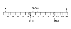
- FIG. 1 is a schematic cross-sectional view of an extruder used in the method for producing polysulfone pellets of this embodiment.
- polysulfone and other components to be added as necessary are melt-kneaded and pelletized.
- an extruder 10 used in this embodiment includes a motor 1 accommodated in a motor box 1a, a cylinder 2 provided adjacent to the motor box 1a, and a cylinder 2 inserted into the motor 2. 1 and a screw 3 connected to 1.
- the cylinder 2 includes a supply unit 4 and an additional unit 6 for supplying polysulfone and other components kneaded into the polysulfone into the cylinder 2, and two vent units 5 (first-stage) for discharging volatile components (gas) generated in the cylinder 2.
- vent part 51, 2nd vent part 52), and the strand die 9 which shape
- the screw 3 includes a transport unit 7 for transporting resin and a kneading unit 8 (first kneading unit 81, second kneading unit 82) for performing resin kneading.
- the polysulfone used as a raw material in the production method of this embodiment typically has a divalent aromatic group (residue obtained by removing two hydrogen atoms bonded to the aromatic ring from an aromatic compound) and a sulfonyl group.
- the polysulfone preferably has a repeating unit represented by the following formula (1) (hereinafter sometimes referred to as “repeating unit (1)”).
- a repeating unit represented by formula (2) hereinafter sometimes referred to as “repeating unit (2)”
- a repeating unit represented by formula (3) below hereinafter referred to as “repeating unit (3)”.
- And may have one or more other repeating units.
- Ph 1 and Ph 2 each independently represent a phenylene group.
- the hydrogen atoms in the phenylene group may each independently be substituted with an alkyl group, an aryl group, or a halogen atom.
- Ph 3 and Ph 4 each independently represents a phenylene group.
- the hydrogen atoms in the phenylene group may each independently be substituted with an alkyl group, an aryl group, or a halogen atom.
- R represents an alkylidene. Represents a group, oxygen atom or sulfur atom.
- Ph 5 represents a phenylene group.
- the hydrogen atoms in the phenylene group may be each independently substituted with an alkyl group, an aryl group or a halogen atom.
- N represents an integer of 1 to 3.
- n is 2 or more, a plurality of Ph 5 may be the same or different from each other.
- the phenylene group represented by any of Ph 1 to Ph 5 may be a p-phenylene group, an m-phenylene group, or an o-phenylene group, but is preferably a p-phenylene group.
- alkyl group which may substitute a hydrogen atom in the phenylene group examples include an alkyl group having 1 to 10 carbon atoms, and more specifically, a methyl group, an ethyl group, an n-propyl group, an isopropyl group. N-butyl group, isobutyl group, s-butyl group, t-butyl group, n-hexyl group, 2-ethylhexyl group, n-octyl group, n-decyl group and the like.
- Examples of the aryl group which may substitute a hydrogen atom in the phenylene group include aryl groups having 6 to 20 carbon atoms, and more specifically, a phenyl group, an o-tolyl group, an m-tolyl group, Examples thereof include a p-tolyl group, a 1-naphthyl group, and a 2-naphthyl group.
- the number is preferably 2 or less for each phenylene group, more preferably, 1 or less.
- the alkylidene group includes an alkylidene group having 1 to 5 carbon atoms, and more specifically, a methylene group, an ethylidene group, an isopropylidene group, and Examples thereof include 1-butylidene group.
- the polysulfone having such a structure preferably has the repeating unit (1) in an amount of 50 mol% or more, more preferably 80 mol% or more, based on the total number of moles of all repeating units. More preferably, it has substantially only the repeating unit (1).
- the polysulfone may have two or more repeating units (1) to (3) independently of each other.
- the polysulfone described above can be produced by polycondensation of a dihalogenosulfone compound corresponding to the repeating unit constituting the polysulfone and a dihydroxy compound.
- a resin having a repeating unit (1) uses a compound represented by the following formula (4) as a dihalogenosulfone compound (hereinafter sometimes referred to as “compound (4)”), and a dihydroxy compound represented by the following formula: It can be produced by using the compound represented by (5) (hereinafter sometimes referred to as “compound (5)”).
- X 1 and X 2 each independently represent a halogen atom. Ph 1 and Ph 2 are as defined above.
- the resin having the repeating unit (1) and the repeating unit (2) uses the above-described compound (4) as a dihalogenosulfone compound, and a compound represented by the following formula (6) as a dihydroxy compound (hereinafter, “ It may be produced by using the compound (sometimes referred to as “compound (6)”).
- the resin having the repeating unit (1) and the repeating unit (3) uses the above-mentioned compound (4) as a dihalogenosulfone compound, and a compound represented by the following formula (7) as a dihydroxy compound (hereinafter, “ It may be produced by using the compound (7) ”.
- halogen atom for X 1 and X 2 , a chlorine atom, a bromine atom or an iodine atom is preferable independently.
- the polycondensation of polysulfone is preferably carried out in a solvent using an alkali metal carbonate.
- alkali metal carbonate include carbonate which is a normal salt, bicarbonate (hydrogencarbonate) which is an acidic salt, or a mixture of both.
- carbonate sodium carbonate and potassium carbonate are preferably used, and as the bicarbonate, sodium bicarbonate and potassium bicarbonate are preferably used.
- Solvents for polycondensation include dimethyl sulfoxide, 1-methyl-2-pyrrolidone, sulfolane (1,1-dioxothyrane), 1,3-dimethyl-2-imidazolidinone, 1,3-diethyl-2-imidazolidinone
- Organic polar solvents such as dimethylsulfone, diethylsulfone, diisopropylsulfone and diphenylsulfone are preferably used.
- the polysulfone used in the production method of the present embodiment has a reduced viscosity of preferably 0.3 dL / g or more, more preferably 0.4 dL / g or more and 0.6 dL / g or less, and further preferably 0.45 dL / g or more and 0. .55 dL / g or less.
- the higher the reduced viscosity the easier it is to improve the heat resistance, strength, and rigidity.
- the reduced viscosity is too high, the melting temperature and the melt viscosity tend to increase, and the temperature required for the molding tends to increase.
- the molar ratio of the dihalogenosulfone compound to the dihydroxy compound, the alkali metal carbonate so that a polysulfone having a desired reduced viscosity is obtained in consideration of the degree of this side reaction. It is preferable to adjust the amount of salt used, polycondensation temperature and polycondensation time, and those skilled in the art will know the molar ratio of the dihalogenosulfone compound to the dihydroxy compound, the amount of alkali metal carbonate used, the polycondensation temperature and the polycondensation. A polysulfone having a desired reduced viscosity can be obtained by appropriately adjusting the condensation time.
- the polysulfone used as a raw material in the production method of the present embodiment preferably has an average particle size of 1000 ⁇ m or less.
- the average particle size exceeds 1000 ⁇ m, the melting of the polysulfone in the kneading part 8 may be insufficient.
- the average particle size is 1000 ⁇ m or less, the polysulfone is sufficiently melted in the kneading section 8.
- the smaller the average particle diameter the easier the melting of the polysulfone in the kneading part 8 is.
- it is usually preferably 10 ⁇ m or more.
- the “average particle size” means a sieve having openings of 1400 ⁇ m, 850 ⁇ m, 710 ⁇ m, 500 ⁇ m, 250 ⁇ m, 150 ⁇ m, 100 ⁇ m, 50 ⁇ m, 20 ⁇ m, 10 ⁇ m, etc. Stacked to be small, 100 g of sample was put into a 1400 ⁇ m sieve, vibrated for 10 minutes with a vibration sieve, and then the weight average particle diameter obtained from the Rosin-Rammler distribution formula using the measurement result of the sample weight on each sieve. is there.
- Polysulfone composition Such polysulfone may be blended with one or more other components such as fillers, additives, or resins other than polysulfone, if necessary, to form a polysulfone composition.
- the filler may be a fibrous filler (fibrous filler), a plate-like filler (plate-like filler), or a spherical or other granular filler other than fibrous or plate-like. It may be.
- the filler may be an inorganic filler or an organic filler.
- fibrous inorganic fillers examples include glass fibers; carbon fibers such as bread-based carbon fibers or pitch-based carbon fibers; ceramic fibers such as silica fibers, alumina fibers or silica-alumina fibers; and metal fibers such as stainless fibers.
- whiskers such as potassium titanate whisker, barium titanate whisker, wollastonite whisker, aluminum borate whisker, silicon nitride whisker and silicon carbide whisker can also be mentioned.
- fibrous organic fillers examples include polyester fibers and aramid fibers.
- Examples of the plate-like inorganic filler include talc, mica, graphite, wollastonite, glass flake, barium sulfate and calcium carbonate.
- Mica may be muscovite, phlogopite, fluorine phlogopite, tetrasilicon mica, or the like.
- Examples of the granular inorganic filler include silica, alumina, titanium oxide, glass beads, glass balloons, boron nitride, silicon carbide, and calcium carbonate.
- the content of these fillers is preferably 0 to 100 parts by mass with respect to 100 parts by mass of polysulfone.
- additives include antioxidants, heat stabilizers, ultraviolet absorbers, antistatic agents, surfactants, flame retardants, and colorants.
- the content of the additive is preferably 0 to 5 parts by mass with respect to 100 parts by mass of the polysulfone.
- examples of resins other than polysulfone to be melt-kneaded with polysulfone include thermoplastic resins other than polysulfone such as polypropylene, polyamide, polyester, polyphenylene sulfide, polyether ketone, polycarbonate, polyphenylene ether or polyetherimide; and phenol resins,
- a thermosetting resin such as an epoxy resin, a polyimide resin, or a cyanate resin can be used.
- the content of the resin other than polysulfone is preferably 0 to 20 parts by mass with respect to 100 parts by mass of polysulfone.
- these fillers, additives, or components such as resins other than polysulfone are used after being melt-kneaded with polysulfone, these components may be supplied from the supply unit 4 in the state of a composition mixed with polysulfone. However, if it supplies from the additional part 6, melt-kneading can be made more uniform and it is preferable.
- the extruder 10 of the present embodiment is a twin screw extruder in which two screws 3 are inserted into a cylinder 2.
- twin-screw extruders include those with a single screw rotating in the same direction to those with a triple screw, parallel shaft type with different direction rotation, oblique shaft type or incomplete meshing type, etc.
- the twin screw extruder is preferred.
- the cylinder 2 is provided with a supply portion 4 for supplying at least polysulfone into the cylinder 2 at the most upstream position, and from the supply portion 4 toward the downstream side, the first vent portion 51, the additional portion 6, and the second vent.
- the part 52 is provided in this order.
- the side of the cylinder on which the supply section is provided is referred to as “upstream”
- the side of the cylinder on which the strand die is provided is referred to as “downstream”.
- the supply unit 4 and the additional unit 6 include a hopper connected to the inside of the cylinder 2 and a supply device that supplies the resin with a constant mass or a constant capacity.
- Examples of the supply method of the supply device include a belt type, a screw type, a vibration type, and a table type.
- the first vent part 51 is provided downstream of the first kneading part 81.
- the second vent portion 52 is provided on the downstream side of the second kneading portion 82. That is, the 1st vent part 51 is provided corresponding to the 1st kneading part 81, and the 2nd vent part 52 is provided corresponding to the 2nd kneading part 82 one-to-one.
- the vent part 5 on the downstream side of the kneading part 8
- the gas generated in the kneading part 8 is exhausted from the corresponding vent part 5, and the strand can be stably manufactured.
- two or more vent portions 5 may be provided on the downstream side of one kneading portion 8.
- the length of the vent portion 5 (the length in the screw length direction of the opening connecting the outside and the inside of the cylinder 2) is preferably 0.5 to 5 times the screw diameter (D) of the screw 3. . If the length of the vent portion 5 is too short, the deaeration effect is insufficient, and if it is too long, foreign matter is mixed in from the vent portion 5 or vent-up occurs (the molten resin rises from the vent portion). There is a risk. If the length of the vent part 5 is 0.5 to 5 times the screw diameter (D) of the screw 3, the degassing effect is sufficient, and foreign matter is mixed from the vent part 5 There is no risk of it happening.
- the opening width of the vent portion 5 is not less than 0.3 times and not more than 1.5 times the screw diameter (D) of the screw 3. If the opening width of the vent portion 5 is too small, the deaeration effect is insufficient, and if it is too large, foreign matter may enter from the vent portion 5 or vent up may occur. If the opening width of the vent portion 5 is not less than 0.3 times and not more than 1.5 times the screw diameter (D) of the screw 3, the deaeration effect is sufficient, and foreign matter is mixed in or vent-up occurs. There is no fear.
- the vent section 5 may be an open vent system that is open to the atmosphere or a vacuum vent system that is connected to a water-sealed pump, a rotary pump, an oil diffusion pump, a turbo pump, or the like and held in a vacuum.
- the screw 3 has a transport unit 7 for transporting resin and a kneading unit 8 for performing resin kneading.
- the kneading unit 8 is provided at two locations from the upstream side (the first kneading unit 81 and the second kneading unit 82 from the upstream side).
- Such a screw 3 is configured by combining screw elements.
- Conveying unit 7 is composed of forward flight (full flight) screw elements
- kneading unit 8 is composed of screw elements such as full flight, reverse flight, seal ring, forward kneading disc, neutral kneading disc and reverse kneading disc. It is common to be done.
- FIG. 4 is a schematic diagram showing an example of the screw configuration of an extruder used in the method for producing polysulfone pellets of the present invention.
- the first kneading section is composed of a forward kneading disk, a neutral kneading disk, and a full flight screw element from the upstream side.
- screw elements without R, N, or L signify full flight.
- pellets are manufactured by melting and kneading the raw material polysulfone using a screw having a screw configuration of the first kneading section 81 that does not have a reverse kneading disk.
- the polysulfone hardly melts in the first kneading section 81, and the polysulfone that has passed through the first kneading section 81 is hardly completely melted.
- the gas generated from the polysulfone by the time it passes through the first kneading portion 81 in the cylinder 2 reaches the first vent portion 51 through the gap between the polysulfone powder or pellets that are not in a completely melted state. It is discharged outside.
- various problems caused by the generation of gas specifically, the problem that polysulfone does not bite into the flight of the screw, and the chute caused by the gas generated in the first kneading part 81 flowing into the supply part 4 It is possible to suppress the up.
- the screw of the first kneading unit 81 is preferably composed of a screw element selected from the group consisting of a forward kneading disk and a full flight. More preferably, it is composed only of disks. In addition, when the full flight is included in the configuration, it is preferable that the pitch of the full flight is larger because the conveyance capability becomes higher.
- the ratio (L1 / D) between the length (L1) of the first kneading part 81 and the screw diameter (D) is preferably 0.5 or more and 5 or less.
- L1 / D is less than 0.5, the melting of polysulfone becomes insufficient, and when L1 / D exceeds 5, the gas generated in the first kneading unit 81 flows into the supply unit 4 to cause shoot up, There is a possibility that the discharge amount is reduced.
- the ratio (L1 / D) of the length (L1) of the first kneading part 81 to the screw diameter (D) is 0.5 or more and 5 or less, the polysulfone is sufficiently melted. Since the generated gas does not flow into the supply unit 4, shoot-up does not occur and the discharge amount does not decrease. Note that L1 and D are the same scale unit.
- the length (L1) of the first kneading section 81 is a value obtained by summing the lengths of the screw elements constituting the first kneading section 81.
- the screw diameter (D) is the diameter of a circle circumscribing the screw.
- the ratio (L2 / D) between the screw length (L2) and the screw diameter (D) is preferably 25 or more. If L2 / D is less than 25, the polysulfone may be insufficiently melted.
- the ratio (L2 / D) between the screw length (L2) and the screw diameter (D) is usually 100 or less. Note that L2 and D are the same scale unit.
- the screw length (L2) is the length of the portion accommodated in the cylinder 2 and contributing to the transport and kneading of the resin.
- the screw diameter (D) is the diameter of a circle circumscribing the screw.
- the resin temperature of the polysulfone after kneading in the first kneading part 81 is preferably heated to a temperature lower than the flow start temperature of the polysulfone used as a raw material, and more preferably heated to a temperature lower than the flow start temperature.
- the resin temperature is lower than the flow start temperature and heated so as to be as close as possible to the flow start temperature, so that the melting and kneading of the polysulfone proceeds appropriately.
- the flow start temperature of the polysulfone varies depending on the specific polysulfone used, but can be determined by measuring in advance using, for example, a flow tester, as described in Examples below.
- mixing of the 1st kneading part 81 and the 2nd kneading part 82 can be measured, for example using a non-contact-type thermometer, as described in the below-mentioned Example.
- the second kneading unit 82 is not limited in the screw configuration, and various configurations can be adopted as long as the configuration is such that the polysulfone is melt-kneaded and completely melt-kneaded.
- a screw configuration of the second kneading part 82 a screw configuration combining a forward kneading disc (5R), a neutral kneading disc (5N), and a reverse kneading disc (5L) from the upstream side is illustrated. Can do.
- the filler etc. which are supplied from the addition part 6 can be knead
- the second kneading section is composed of a forward kneading disc, a forward kneading disc, a neutral kneading disc, a forward kneading disc, a neutral kneading disc, and a reverse kneading disc from the upstream side.
- An example is shown.
- the resin temperature of the polysulfone after kneading is heated to a temperature higher than the flow start temperature of the polysulfone used.
- the resin temperature of the polysulfone after kneading in the second kneading part 82 is usually preferably 450 ° C. or lower.
- the fibrous filler when used as a filler, the fibrous filler may break during kneading and physical properties such as mechanical strength may be reduced. Therefore, when using a fibrous filler, the fibrous filler is supplied from the additional unit 6, and the kneading of the polysulfone and the fibrous filler is mainly performed in the second kneading unit 82, thereby kneading the fibrous filler. Is preferably shortened.
- a strand die 9 having a nozzle hole 9 a communicating with the cylinder 2 is provided at the downstream end of the cylinder 2.
- the strand formed by being extruded from the strand die 9 can be pelletized using a known means such as a pelletizer, a fan cutter, a strand cutter or hot cut.
- pelletization is performed using the above twin screw extruder.
- the strand can be stably formed. As a result, it is possible to improve the productivity of pellets.
- the extruder which has the additional part 6 and the 2nd kneading part 82 is used, the extruder which does not have these can also be used.
- the flow start temperature of polysulfone was measured using a flow tester (manufactured by Shimadzu Corporation, CFT-500 type). About 2 g of polysulfone was filled in a cylinder equipped with a die having a nozzle having an inner diameter of 1 mm and a length of 10 mm, and the temperature was raised at a rate of 4 ° C./min under a load of 9.8 MPa (100 kg / cm 2 ). Was melted and extruded from the nozzle, and a temperature showing a viscosity of 4800 Pa ⁇ s (48000 poise) was measured as a flow start temperature.
- FIG. 2 is a schematic view showing a heater provided in the cylinder 2 for the extruder used in Example 1.
- FIG. 2 the position of each component of the extruder with respect to the heater is shown using the same reference numerals as in FIG. 1.
- PCM30 type manufactured by Ikekai Tekko Co., Ltd. twin-screw extruder
- the screw has a ratio of the length (L1) of the first kneading portion 81 to the screw diameter (D) of 1.67, and the screw configuration of the first kneading portion 81 is the forward kneading disc (5R) from the upstream side.
- a combination of three, a screw configuration of the second kneading unit 82 is a combination of a forward kneading disc (5R), a neutral kneading disc (5N) and a reverse kneading disc (5L) from the upstream side, a conveying unit The one whose screw configuration is full flight was used.
- the first kneading part 81 of the screw is arranged at a position overlapping with the heater C4, and the second kneading part 82 is arranged at a position overlapping with the heater C9.
- the position of each kneading part is shown by shading.
- polysulfone (Sumika Excel 4100P, manufactured by Sumitomo Chemical Co., Ltd., flow start temperature 310 ° C., average particle size 817 ⁇ m) was supplied from the supply unit 4 and melt kneaded to prepare polysulfone pellets. .
- each set temperature of the cylinder was C0: 280 ° C., C1 to C4: 320 ° C., C5 to C11: 340 ° C., a die: 360 ° C., and the screw rotation speed was 200 rpm. Further, the vacuum degree of the first vent portion 51 was maintained so that the gauge pressure was ⁇ 0.08 MPa (atmospheric pressure was 0 MPa).
- Example 2 Polysulfone pellets were produced in the same manner as in Example 1 except that the screw configuration of the first kneading part 81 was set to full flight.
- Example 3 Polysulfone was used in the same manner as in Example 1 except that the screw structure of the first kneading part 81 was a combination of a forward kneading disc (5R), a neutral kneading disc (5N) and a neutral kneading disc (5N) from the upstream side. A pellet was prepared.
- 5R forward kneading disc
- N neutral kneading disc
- 5N neutral kneading disc
- Polysulfone is the same as in Example 1 except that the screw structure of the first kneading part 81 is a combination of a forward kneading disk (5R), a neutral kneading disk (5N) and a reverse kneading disk (5L) from the upstream side.
- a pellet was prepared.
- FIG. 3 is a schematic diagram showing a heater provided in the cylinder 2 for the extruder used in Example 4.
- the position of each component of the extruder with respect to the heater is shown using the same reference numerals as in FIG.
- PCM30 type manufactured by Ikekai Tekko Co., Ltd. a twin-screw extruder
- the screw has a ratio of the length (L1) of the first kneading portion 81 to the screw diameter (D) of 1.67, and the screw configuration of the first kneading portion 81 is the forward kneading disc (5R) from the upstream side.
- a screw structure of the second kneading part 82 is a combination of a 5 order kneading disc (5R), a neutral kneading disc (5N) and a reverse kneading disc (5L) from the upstream side, The screw configuration of the part was full flight.
- the first kneading part 81 of the screw is arranged at a position (shown by shading) that overlaps the heater C4, and the second kneading part 82 is arranged at a position (shown by shading) that overlaps the heater C9. Yes.
- polysulfone (Sumika Excel 4100P, manufactured by Sumitomo Chemical Co., Ltd.) is supplied from the supply unit 4, and 20 parts by weight of glass fiber (from Owens Corning, CS03JAPX-1) is supplied from the additional unit 6. Then, melt kneading was performed to produce polysulfone pellets.
- each set temperature of the cylinder was C0: 280 ° C., C1 to C4: 320 ° C., C5 to C11: 340 ° C., a die: 360 ° C., and the screw rotation speed was 200 rpm.
- the gauge pressure of the vacuum vent was kept at ⁇ 0.08 MPa.
- Example 2 Polysulfone was used in the same manner as in Example 1 except that the first kneading part 81 had a screw configuration of a forward kneading disk (5R), a neutral kneading disk (5N) and a reverse kneading disk (5L) from the upstream side. A pellet was prepared.
- Example 4 the resin temperature and the maximum discharge amount of polysulfone after kneading in the first kneading part 81 and the second kneading part 82 are shown in Table 2 below.
- the present invention it is possible to provide a method for producing polysulfone pellets in which a stable strand of polysulfone can be obtained and the productivity of the strand, and thus the polysulfone pellet, can be improved.
Landscapes
- Engineering & Computer Science (AREA)
- Mechanical Engineering (AREA)
- Chemical & Material Sciences (AREA)
- Health & Medical Sciences (AREA)
- Chemical Kinetics & Catalysis (AREA)
- Medicinal Chemistry (AREA)
- Polymers & Plastics (AREA)
- Organic Chemistry (AREA)
- Processing And Handling Of Plastics And Other Materials For Molding In General (AREA)
- Processes Of Treating Macromolecular Substances (AREA)
- Compositions Of Macromolecular Compounds (AREA)
Abstract
本発明は、ベント式の二軸押出機を用いるポリスルホンペレットの製造方法であって、前記二軸押出機は、最上流のベント部の上流側に配置された混練部のうち、前記最上流のベント部に最も近い位置の前記混練部が、逆ニーディングディスクを用いないスクリュー構成であり、前記ポリスルホンペレットの製造方法は、原料のポリスルホンを供給部から供給すること、前記ポリスルホンを加熱して溶融する第1の工程、前記ポリスルホンを混練する第1の工程、シリンダー内で発生したガスを前記ベント部から排出すること、前記混練したポリスルホンをストランドダイから押し出してストランドを形成すること、及び前記ストランドを切断してペレット化すること、を含む前記ポリスルホンペレットの製造方法に関する。本発明によれば、押出機内で発生するガスによる不具合を生じにくくし、生産性を向上させることができるポリスルホンペレットの製造方法を提供することができる。
Description
本発明は、ポリスルホンペレットの製造方法に関するものである。
本願は、2011年3月17日に、日本に出願された特願2011-059473号に基づき優先権を主張し、その内容をここに援用する。
本願は、2011年3月17日に、日本に出願された特願2011-059473号に基づき優先権を主張し、その内容をここに援用する。
ポリスルホンは非晶性樹脂であり、優れた耐加水分解性、耐熱性、機械強度及び難燃性、さらには耐クリープ性などの特徴を有するため、電気・電子部品、自動車部品、医療機器及び食品容器などの幅広い分野で使用されている。
一般に、ポリスルホンは、押出機を用いて溶融混練し、ストランドダイから押し出すことでストランドを形成した後、前記ストランドを切断し、ペレット状の製品としている。また、ポリスルホンの機械的性質を改良するためにガラス繊維等の繊維状フィラーを溶融混練する場合、ポリスルホン、及びガラス繊維をドライブレンドして混合物とした後、上記と同様に、前記混合物を押出機で溶融混練し、ペレット化する方法が知られている(例えば、特許文献1参照)。
一般に、樹脂のペレット化に際しては、樹脂の溶融時にガスが発生することがある。このガスが押出機のホッパー(供給部)に流入すると、ホッパーの樹脂が吹き上がり(以下、このような現象のことを「シュートアップ」と称することがある)、押出機への樹脂の供給が滞って、吐出量が低下することにより、ストランドの生産性を低下させる。また、上述のガスが、押出機スクリューへの樹脂の噛み込みを阻害し、ストランドを安定的に製造できなくする。
本発明はこのような事情に鑑みてなされたものであって、押出機スクリューにおいて樹脂の溶融を促進する混練部の構成を工夫することで、押出機内で発生するガスによる不具合を生じにくくし、ストランド、ひいてはポリスルホンペレットの生産性を向上させることができるポリスルホンペレットの製造方法を提供することを目的とする。
上記の課題を解決するため、本発明のポリスルホンペレットの製造方法は、ベント式の二軸押出機を用いてポリスルホンを溶融押出し、形成されるストランドを切断してペレットを製造するポリスルホンペレットの製造方法であって、前記二軸押出機として、シリンダーが、少なくともポリスルホンを供給する供給部と、前記シリンダー内で生じる揮発性成分を排出する1以上のベント部と、を有し、スクリューが、前記シリンダー内において前記供給部と前記ベント部との間に配置される1以上の混練部を有しており、最上流の前記ベント部の上流側に配置された前記混練部のうち、前記最上流のベント部に最も近い位置の前記混練部が、逆ニーディングディスクを用いないスクリュー構成であるものを用いることを特徴とする。
本発明においては、前記最上流のベント部に最も近い位置の混錬部で混練された後のポリスルホンの樹脂温度が、ポリスルホンの流動開始温度以下となるように溶融押出することが望ましい。
本発明においては、前記最上流のベント部に最も近い位置の混練部が、順ニーディングディスクで構成されたスクリュー構成であることが望ましい。
本発明においては、前記混錬部の長さ(L1)とスクリュー径(D)との比(L1/D)が、0.5~5であることが望ましい。
本発明においては、スクリュー長さ(L2)とスクリュー径(D)との比(L2/D)が、25以上であることが望ましい。
本発明においては、前記二軸押出機は、前記ベント部が、最上流に設けられた第1ベント部と、前記第1ベント部の下流側に設けられた第2ベント部と、を含み、前記混練部が、前記シリンダー内において前記供給部と前記第1ベント部との間に配置される第1混練部と、前記第1ベント部と前記第2ベント部との間に配置される第2混練部と、を含み、前記シリンダーが、前記第1ベント部と、前記シリンダー内において前記第2混練部が配置される位置と、の間に設けられた追加部を有しており、前記供給部から前記組成物を供給するとともに、前記追加部から前記組成物に添加する成分を供給し、前記第2混練部で混練した後のポリスルホンの樹脂温度が、ポリスルホンの流動開始温度以上となるように溶融混練して、ペレットを製造することが望ましい。
本発明においては、前記追加部から供給する成分が、繊維状フィラーであることが望ましい。
本発明においては、ポリスルホンの平均粒径が1000μm以下であることが望ましい。
すなわち、本発明は以下の側面を有する。
<1>ベント式の二軸押出機を用いるポリスルホンペレットの製造方法であって、
ここで、前記二軸押出機は、少なくとも、モーターと、シリンダーと、スクリューと、ストランドダイとを有し、
前記スクリューは、前記モーターに接続されて前記シリンダー内に挿入されており、前記ストランドダイは、前記シリンダーの最下流部に設置されており、
前記シリンダーが、少なくとも、原料のポリスルホンを供給する供給部と、シリンダー内のポリスルホンを加熱するヒーターと、前記シリンダー内で生じるガスを排出する1又は2以上のベント部と、を有し、
前記スクリューが、前記シリンダー内において前記供給部と前記ベント部との間に配置される1又は2以上の混練部を有しており、
最上流の前記ベント部の上流側に配置された前記混練部のうち、前記最上流のベント部に最も近い位置の前記混練部が、逆ニーディングディスクを用いないスクリュー構成であり、
前記ポリスルホンペレットの製造方法は、
原料のポリスルホンを前記供給部から供給すること、
前記ポリスルホンを加熱して溶融する第1の工程、
前記ポリスルホンを混練する第1の工程、
前記シリンダー内で発生したガスを前記ベント部から排出すること、
前記混練したポリスルホンを前記ストランドダイから押し出してストランドを形成すること、及び
前記ストランドを切断してペレット化すること、を含む前記ポリスルホンペレットの製造方法;
<2>前記ポリスルホンを加熱して溶融する第1の工程及び前記ポリスルホンを混練する第1の工程が前記最上流のベント部に最も近い位置の混錬部で行われ、混練された後のポリスルホンの樹脂温度が、ポリスルホンの流動開始温度以下となるよう加熱する、前記<1>に記載のポリスルホンペレットの製造方法;
<3>前記最上流のベント部に最も近い位置の混練部が、順ニーディングディスクで構成されたスクリュー構成であり、前記ポリスルホンを加熱して溶融する第1の工程及び前記ポリスルホンを混練する第1の工程が順ニーディングディスクで構成されたスクリュー構成である混練部で行われることを含む、前記<1>又は<2>に記載のポリスルホンペレットの製造方法;
<4>前記混錬部の長さ(L1)とスクリュー径(D)との比(L1/D)が、0.5~5である、前記<1>から<3>のいずれか1項に記載のポリスルホンペレットの製造方法;
<5>スクリュー長さ(L2)とスクリュー径(D)との比(L2/D)が、25以上である、前記<1>から<4>のいずれか1項に記載のポリスルホンペレットの製造方法;
<6>前記二軸押出機は、前記ベント部が、最上流に設けられた第1ベント部と、前記第1ベント部の下流側に設けられた第2ベント部と、を含み、
前記混練部が、前記シリンダー内において前記供給部と前記第1ベント部との間に配置される第1混練部と、前記第1ベント部と前記第2ベント部との間に配置される第2混練部と、を含み、
前記シリンダーが、前記第1ベント部と、前記シリンダー内において前記第2混練部が配置される位置と、の間に設けられた追加部を有しており、
前記ポリスルホンペレットの製造方法が、
前記ポリスルホンを加熱して溶融する第2の工程、
前記ポリスルホンに添加する成分を前記追加部から供給すること、
前記ポリスルホンを加熱して溶融する第2の工程、及び
前記ポリスルホンを混練する第2の工程、を更に含み、
ここで、前記ポリスルホンを加熱して溶融する第2の工程及び前記ポリスルホンを混練する第2の工程が、前記第2混練部で行われ、前記第2混練部で混練された後のポリスルホンの樹脂温度が、ポリスルホンの流動開始温度以上となるように加熱する、前記<1>から<5>のいずれか1項に記載のポリスルホンペレットの製造方法;
<7>前記追加部から供給する成分が、繊維状フィラーである、前記<6>に記載のポリスルホンペレットの製造方法;
<8>原料のポリスルホンの平均粒径が1000μm以下である、前記<1>から<7>のいずれか1項に記載のポリスルホンペレットの製造方法;
<9>原料のポリスルホンがポリスルホン組成物である、前記<1>から<8>のいずれか1項に記載のポリスルホンペレットの製造方法;並びに
<10>前記シリンダー内で発生したガスを前記第2ベント部から排出することを更に含む、前記<1>から<9>のいずれか1項に記載のポリスルホンペレットの製造方法。
すなわち、本発明は以下の側面を有する。
<1>ベント式の二軸押出機を用いるポリスルホンペレットの製造方法であって、
ここで、前記二軸押出機は、少なくとも、モーターと、シリンダーと、スクリューと、ストランドダイとを有し、
前記スクリューは、前記モーターに接続されて前記シリンダー内に挿入されており、前記ストランドダイは、前記シリンダーの最下流部に設置されており、
前記シリンダーが、少なくとも、原料のポリスルホンを供給する供給部と、シリンダー内のポリスルホンを加熱するヒーターと、前記シリンダー内で生じるガスを排出する1又は2以上のベント部と、を有し、
前記スクリューが、前記シリンダー内において前記供給部と前記ベント部との間に配置される1又は2以上の混練部を有しており、
最上流の前記ベント部の上流側に配置された前記混練部のうち、前記最上流のベント部に最も近い位置の前記混練部が、逆ニーディングディスクを用いないスクリュー構成であり、
前記ポリスルホンペレットの製造方法は、
原料のポリスルホンを前記供給部から供給すること、
前記ポリスルホンを加熱して溶融する第1の工程、
前記ポリスルホンを混練する第1の工程、
前記シリンダー内で発生したガスを前記ベント部から排出すること、
前記混練したポリスルホンを前記ストランドダイから押し出してストランドを形成すること、及び
前記ストランドを切断してペレット化すること、を含む前記ポリスルホンペレットの製造方法;
<2>前記ポリスルホンを加熱して溶融する第1の工程及び前記ポリスルホンを混練する第1の工程が前記最上流のベント部に最も近い位置の混錬部で行われ、混練された後のポリスルホンの樹脂温度が、ポリスルホンの流動開始温度以下となるよう加熱する、前記<1>に記載のポリスルホンペレットの製造方法;
<3>前記最上流のベント部に最も近い位置の混練部が、順ニーディングディスクで構成されたスクリュー構成であり、前記ポリスルホンを加熱して溶融する第1の工程及び前記ポリスルホンを混練する第1の工程が順ニーディングディスクで構成されたスクリュー構成である混練部で行われることを含む、前記<1>又は<2>に記載のポリスルホンペレットの製造方法;
<4>前記混錬部の長さ(L1)とスクリュー径(D)との比(L1/D)が、0.5~5である、前記<1>から<3>のいずれか1項に記載のポリスルホンペレットの製造方法;
<5>スクリュー長さ(L2)とスクリュー径(D)との比(L2/D)が、25以上である、前記<1>から<4>のいずれか1項に記載のポリスルホンペレットの製造方法;
<6>前記二軸押出機は、前記ベント部が、最上流に設けられた第1ベント部と、前記第1ベント部の下流側に設けられた第2ベント部と、を含み、
前記混練部が、前記シリンダー内において前記供給部と前記第1ベント部との間に配置される第1混練部と、前記第1ベント部と前記第2ベント部との間に配置される第2混練部と、を含み、
前記シリンダーが、前記第1ベント部と、前記シリンダー内において前記第2混練部が配置される位置と、の間に設けられた追加部を有しており、
前記ポリスルホンペレットの製造方法が、
前記ポリスルホンを加熱して溶融する第2の工程、
前記ポリスルホンに添加する成分を前記追加部から供給すること、
前記ポリスルホンを加熱して溶融する第2の工程、及び
前記ポリスルホンを混練する第2の工程、を更に含み、
ここで、前記ポリスルホンを加熱して溶融する第2の工程及び前記ポリスルホンを混練する第2の工程が、前記第2混練部で行われ、前記第2混練部で混練された後のポリスルホンの樹脂温度が、ポリスルホンの流動開始温度以上となるように加熱する、前記<1>から<5>のいずれか1項に記載のポリスルホンペレットの製造方法;
<7>前記追加部から供給する成分が、繊維状フィラーである、前記<6>に記載のポリスルホンペレットの製造方法;
<8>原料のポリスルホンの平均粒径が1000μm以下である、前記<1>から<7>のいずれか1項に記載のポリスルホンペレットの製造方法;
<9>原料のポリスルホンがポリスルホン組成物である、前記<1>から<8>のいずれか1項に記載のポリスルホンペレットの製造方法;並びに
<10>前記シリンダー内で発生したガスを前記第2ベント部から排出することを更に含む、前記<1>から<9>のいずれか1項に記載のポリスルホンペレットの製造方法。
本発明によれば、ポリスルホンの安定したストランドが得られ、ストランド、ひいてはポリスルホンペレットの生産性の向上を図ることが可能となるポリスルホンペレットの製造方法を提供することができる。
以下、図を参照しながら、本発明の実施形態に係るポリスルホンペレットの製造方法について説明する。なお、以下の全ての図面においては、図面を見やすくするため、各構成要素の寸法や比率などを適宜調整して図示するが、本発明は、それらの図示した寸法及び比率に限定されるものではない。
図1は、本実施形態のポリスルホンペレットの製造方法で用いる押出機の概略断面図である。本実施形態の製造方法では、図1に示す押出機を用いて、ポリスルホン及び必要に応じて添加するその他の成分を溶融混練し、ペレット化を行う。
図1に示すように、本実施形態で用いる押出機10は、モーターボックス1aに収容されたモーター1と、モーターボックス1aに隣接して設けられたシリンダー2と、シリンダー2内に挿入され、モーター1と接続されたスクリュー3と、を有している。
シリンダー2は、シリンダー2内にポリスルホンやポリスルホンに混練するその他の成分を供給する供給部4及び追加部6と、シリンダー2内で生じる揮発性成分(ガス)を排出する2つのベント部5(第1ベント部51、第2ベント部52)と、溶融した樹脂を成形するストランドダイ9と、を有している。
また、スクリュー3は、樹脂搬送を行うための搬送部7と、樹脂混練を行うための混練部8(第1混練部81、第2混練部82)と、を有している。
以下、本実施形態の製造方法に用いるポリスルホン等について説明した後、図1を参照しながら押出機10について詳細に説明する。
(ポリスルホン)
本実施形態の製造方法で原料として用いるポリスルホンは、典型的には、2価の芳香族基(芳香族化合物から、その芳香環に結合した水素原子を2個除いてなる残基)とスルホニル基(-SO2-)と酸素原子とを含む繰返し単位を有する樹脂である。
本実施形態の製造方法で原料として用いるポリスルホンは、典型的には、2価の芳香族基(芳香族化合物から、その芳香環に結合した水素原子を2個除いてなる残基)とスルホニル基(-SO2-)と酸素原子とを含む繰返し単位を有する樹脂である。
前記ポリスルホンは、耐熱性や耐薬品性の点から、下記式(1)で表される繰返し単位(以下、「繰返し単位(1)」ということがある。)を有することが好ましく、さらに、下記式(2)で表される繰返し単位(以下、「繰返し単位(2)」ということがある。)や、下記式(3)で表される繰返し単位(以下、「繰返し単位(3)」ということがある。)等の他の繰返し単位を1種以上有していてもよい。



Ph1~Ph5のいずれかで表されるフェニレン基は、p-フェニレン基、m-フェニレン基、又はo-フェニレン基であってもよいが、p-フェニレン基が好ましい。
前記フェニレン基にある水素原子を置換していてもよいアルキル基としては、炭素数1~10のアルキル基が挙げられ、より具体的には、メチル基、エチル基、n-プロピル基、イソプロピル基、n-ブチル基、イソブチル基、s-ブチル基、t-ブチル基、n-ヘキシル基、2-エチルヘキシル基、n-オクチル基及びn-デシル基等が挙げられる。
前記フェニレン基にある水素原子を置換していてもよいアリール基としては、炭素数6~20のアリール基が挙げられ、より具体的には、フェニル基、o-トリル基、m-トリル基、p-トリル基、1-ナフチル基及び2-ナフチル基等が挙げられる。
前記フェニレン基にある水素原子を置換していてもよいハロゲン原子としては、例えばフッ素原子、塩素原子、臭素原子及びヨウ素原子が挙げられる。
前記フェニレン基にある水素原子がこれらのアルキル基、アリール基又はハロゲン原子で置換されている場合、その数は、前記フェニレン基毎に、それぞれ独立に、好ましくは2個以下であり、より好ましくは1個以下である。
上記式(2)に含まれるRがアルキリデン基である場合、かかるアルキリデン基としては、炭素数1~5のアルキリデン基が挙げられ、より具体的には、メチレン基、エチリデン基、イソプロピリデン基及び1-ブチリデン基等が挙げられる。
このような構造を有するポリスルホンは、繰返し単位(1)を、全繰返し単位のモル数の合計に対して、50モル%以上有することが好ましく、80モル%以上有することがより好ましく、繰返し単位として実質的に繰返し単位(1)のみを有することがさらに好ましい。なお、ポリスルホンは、繰返し単位(1)~(3)を、それぞれ独立に、2種以上有していてもよい。
(ポリスルホンの製造方法)
上述したポリスルホンは、前記ポリスルホンを構成する繰返し単位に対応するジハロゲノスルホン化合物とジヒドロキシ化合物とを重縮合させることにより、製造することができる。
上述したポリスルホンは、前記ポリスルホンを構成する繰返し単位に対応するジハロゲノスルホン化合物とジヒドロキシ化合物とを重縮合させることにより、製造することができる。
例えば、繰返し単位(1)を有する樹脂は、ジハロゲノスルホン化合物として下記式(4)で表される化合物(以下、「化合物(4)」ということがある。)を用い、ジヒドロキシ化合物として下記式(5)で表される化合物(以下、「化合物(5)」ということがある。)を用いることにより、製造することができる。


また、繰返し単位(1)と繰返し単位(2)とを有する樹脂は、ジハロゲノスルホン化合物として上述の化合物(4)を用い、ジヒドロキシ化合物として下記式(6)で表される化合物(以下、「化合物(6)」ということがある。)を用いることにより、製造することができる。

さらに、繰返し単位(1)と繰返し単位(3)とを有する樹脂は、ジハロゲノスルホン化合物として上述の化合物(4)を用い、ジヒドロキシ化合物として下記式(7)で表される化合物(以下、「化合物(7)」ということがある。)を用いることにより、製造することができる。

X1及びX2のハロゲン原子としては、それぞれ独立して、塩素原子、臭素原子又はヨウ素原子が好ましい。
ポリスルホンの重縮合は、炭酸のアルカリ金属塩を用いて、溶媒中で行うことが好ましい。炭酸のアルカリ金属塩としては、正塩である炭酸塩、酸性塩である重炭酸塩(炭酸水素塩)、又は両者の混合物が挙げられる。炭酸塩としては、炭酸ナトリウムや炭酸カリウムが好ましく用いられ、炭酸水素塩としては、重炭酸ナトリウムや重炭酸カリウムが好ましく用いられる。
重縮合の溶媒としては、ジメチルスルホキシド、1-メチル-2-ピロリドン、スルホラン(1,1-ジオキソチラン)、1,3-ジメチル-2-イミダゾリジノン、1,3-ジエチル-2-イミダゾリジノン、ジメチルスルホン、ジエチルスルホン、ジイソプロピルスルホン、ジフェニルスルホン等の有機極性溶媒が好ましく用いられる。
本実施形態の製造方法で用いるポリスルホンは、還元粘度が、好ましくは0.3dL/g以上、より好ましくは0.4dL/g以上0.6dL/g以下、さらに好ましくは0.45dL/g以上0.55dL/g以下である。還元粘度が高いほど、耐熱性や強度・剛性が向上し易いが、あまり高いと、溶融温度や溶融粘度が高くなり易く、その成形に必要な温度が高くなり易い。
前記重縮合においては、仮に副反応が生じなければ、(1)反応基質であるジハロゲノスルホン化合物とジヒドロキシ化合物とのモル比が1:1に近い、(2)炭酸のアルカリ金属塩の使用量が多い、(3)重縮合温度が高い、(4)重縮合時間が長い、といった反応条件であるほど、得られるポリスルホンの重合度が高くなり易く、還元粘度が高くなり易い。しかし、実際は、副生する水酸化アルカリ(アルカリ金属の水酸化物)等により、ハロゲノ基のヒドロキシル基への置換反応や解重合等の副反応が生じ、この副反応により、得られるポリスルホンの重合度が低下し易く、還元粘度が低下し易い。
そのため、重縮合によりポリスルホンを重合する場合、この副反応の度合いも考慮して、所望の還元粘度を有するポリスルホンが得られるように、ジハロゲノスルホン化合物とジヒドロキシ化合物とのモル比、炭酸のアルカリ金属塩の使用量、重縮合温度及び重縮合時間を調整することが好ましく、当業者は、前記ジハロゲノスルホン化合物とジヒドロキシ化合物とのモル比、炭酸のアルカリ金属塩の使用量、重縮合温度及び重縮合時間を適宜調整して、所望の還元粘度を有するポリスルホンを得ることができる。
本実施形態の製造方法で原料として用いるポリスルホンは、その平均粒径が1000μm以下であることが好ましい。平均粒径が1000μmを超えると、混練部8でのポリスルホンの溶融が不十分となる場合がある。一方、平均粒径が1000μm以下であると、混練部8でのポリスルホンの溶融が充分となる。また、前記平均粒径は小さいほど混練部8でのポリスルホンの溶融が容易であるが、原料の取り扱いの観点から、通常、10μm以上であることが好ましい。ここで、本実施形態において「平均粒径」とは、目開きが1400μm、850μm、710μm、500μm、250μm、150μm、100μm、50μm、20μm、10μm等の篩を、下方のものほど目開きが順に小さくなるように積み重ね、試料100gを1400μm篩に投入し、振動篩器で10分振動させた後、各篩上の試料重量の計量結果を用いロジン・ラムラー分布式から求められる重量平均粒径である。
(ポリスルホン組成物)
このようなポリスルホンは、これに必要に応じて充填材、添加剤又はポリスルホン以外の樹脂等、他の成分を1種以上配合して、ポリスルホン組成物としてもよい。
このようなポリスルホンは、これに必要に応じて充填材、添加剤又はポリスルホン以外の樹脂等、他の成分を1種以上配合して、ポリスルホン組成物としてもよい。
充填材は、繊維状充填材(繊維状フィラー)であってもよいし、板状充填材(板状フィラー)であってもよいし、繊維状及び板状以外で、球状その他の粒状充填材であってもよい。また、充填材は、無機充填材であってもよいし、有機充填材であってもよい。
繊維状無機充填材の例としては、ガラス繊維;パン系炭素繊維又はピッチ系炭素繊維等の炭素繊維;シリカ繊維、アルミナ繊維又はシリカアルミナ繊維等のセラミック繊維;及びステンレス繊維等の金属繊維等が挙げられる。また、チタン酸カリウムウイスカー、チタン酸バリウムウイスカー、ウォラストナイトウイスカー、ホウ酸アルミニウムウイスカー、窒化ケイ素ウイスカー及び炭化ケイ素ウイスカー等のウイスカーも挙げることができる。
繊維状有機充填材の例としては、ポリエステル繊維及びアラミド繊維等が挙げられる。
板状無機充填材の例としては、タルク、マイカ、グラファイト、ウォラストナイト、ガラスフレーク、硫酸バリウム及び炭酸カルシウム等が挙げられる。マイカとしては、白雲母、金雲母、フッ素金雲母又は四ケイ素雲母等であってもよい。
粒状無機充填材の例としては、シリカ、アルミナ、酸化チタン、ガラスビーズ、ガラスバルーン、窒化ホウ素、炭化ケイ素及び炭酸カルシウム等が挙げられる。
これらの充填材の含有量は、ポリスルホン100質量部に対して、好ましくは0質量部以上100質量部以下である。
また、添加剤の例としては、酸化防止剤、熱安定剤、紫外線吸収剤、帯電防止剤、界面活性剤、難燃剤及び着色剤等が挙げられる。添加剤の含有量は、ポリスルホン100質量部に対して、好ましくは0質量部以上5質量部以下である。
さらに、ポリスルホンに溶融混練させるポリスルホン以外の樹脂の例としては、ポリプロピレン、ポリアミド、ポリエステル、ポリフェニレンスルフィド、ポリエーテルケトン、ポリカーボネート、ポリフェニレンエーテル又はポリエーテルイミド等のポリスルホン以外の熱可塑性樹脂;及びフェノール樹脂、エポキシ樹脂、ポリイミド樹脂又はシアネート樹脂等の熱硬化性樹脂が挙げられる。ポリスルホン以外の樹脂の含有量は、ポリスルホン100質量部に対して、好ましくは0質量部以上20質量部以下である。
これらの充填材、添加剤又はポリスルホン以外の樹脂等の成分を、ポリスルホンに溶融混練して使用する場合、これらの成分をポリスルホンと混合した組成物の状態で供給部4から供給することとしてもよいが、追加部6から供給すると、溶融混練をより均一にさせることができ好ましい。
(押出機)
次に、本実施形態の製造方法で用いる押出機10について、図1を参照しながら詳細に説明する。
次に、本実施形態の製造方法で用いる押出機10について、図1を参照しながら詳細に説明する。
本実施形態の押出機10は、シリンダー2内に2本のスクリュー3が挿入された二軸押出機である。二軸押出機としては、同方向回転の1条ネジのものから3条ネジのもの、異方向回転の平行軸型、斜軸型又は不完全噛み合い型のもの等が挙げられるが、同方向回転の二軸押出機が好ましい。
シリンダー2には、最上流の位置に、シリンダー2内に少なくともポリスルホンを供給する供給部4が設けられ、供給部4から下流側に向けて、第1ベント部51、追加部6、第2ベント部52、がこの順に設けられている。
本明細書においては、前記シリンダーの前記供給部が設けられた側を「上流」と称し、前記シリンダーの後記ストランドダイが設けられた側を「下流」と称する。
本明細書においては、前記シリンダーの前記供給部が設けられた側を「上流」と称し、前記シリンダーの後記ストランドダイが設けられた側を「下流」と称する。
供給部4や追加部6は、シリンダー2の内部と接続するホッパーと、樹脂を定質量又は定容量で供給する供給装置と、を有している。供給装置の供給方式としては、例えば、ベルト式、スクリュー式、振動式及びテーブル式等が挙げられる。
第1ベント部51は、第1混練部81の下流に設けられている。同様に、第2ベント部52は、第2混練部82の下流側に設けられている。すなわち、第1ベント部51は第1混練部81と1対1に対応して設けられ、第2ベント部52は第2混練部82と1対1に対応して設けられている。このように、ベント部5を混練部8の下流側に設けることで、混練部8で発生したガスが対応するベント部5から排気され、ストランドを安定的に製造することが可能となる。なお、1つの混練部8に対し、下流側に2つ以上のベント部5が設けられていてもよい。
ベント部5の長さ(外部とシリンダー2内部とを接続する開口のスクリュー長さ方向における長さ)は、スクリュー3のスクリュー径(D)の0.5倍以上5倍以下であることが好ましい。ベント部5の長さがあまり短いと、脱気効果が不十分であり、あまり長いと、ベント部5から異物が混入したり、ベントアップ(溶融樹脂がベント部より上昇すること)が起こったりするおそれがある。ベント部5の長さがスクリュー3のスクリュー径(D)の0.5倍以上5倍以下であれば、脱気効果が充分であり、またベント部5から異物が混入したり、ベントアップが起こるおそれがない。
ベント部5の開口幅は、スクリュー3のスクリュー径(D)の0.3倍以上1.5倍以下であることが好ましい。ベント部5の開口幅があまり小さいと、脱気効果が不十分であり、あまり大きいと、ベント部5から異物が混入したり、ベントアップが起こったりするおそれがある。ベント部5の開口幅が、スクリュー3のスクリュー径(D)の0.3倍以上1.5倍以下であれば、脱気効果が充分であり、また異物が混入したり、ベントアップが起こるおそれがない。
ベント部5は、大気に開放されたオープンベント方式であっても、水封式ポンプ、ロータリーポンプ、油拡散ポンプ又はターボポンプ等に接続して真空に保持する真空ベント方式であってもよい。
スクリュー3は、樹脂搬送を行うための搬送部7と、樹脂混練を行うための混練部8と、を有している。混練部8は、上流側から2箇所(上流側から第1混練部81、第2混練部82)に設けられている。
このようなスクリュー3は、スクリューエレメントを組み合わせて構成される。搬送部7は順フライト(フルフライト)のスクリューエレメント、混練部8はフルフライト、逆フライト、シールリング、順ニーディングディスク、ニュートラルニーディングディスク及び逆ニーディングディスク等のスクリューエレメントが組み合わされて構成されるのが一般的である。
(第1混練部)
本発明者らは、ポリスルホンを溶融押出してペレットを製造するに際し、第1混練部81のスクリュー構成に逆ニーディングディスクを設けないことにより、ストランドの製造が安定し、また、吐出量も多くなることを見出した。すなわち、第1混練部81は、フルフライト、順ニーディングディスク及びニュートラルニーディングディスクからなる群より選択されるスクリューエレメントで構成されていることが好ましい。
図4は、本発明のポリスルホンペレットの製造方法で用いる押出機のスクリュー構成の例を示す模式図である。図4では、第1混練部が、上流側から、順ニーディングディスク、ニュートラルニーディングディスク及びフルフライトのスクリューエレメントで構成された例を示している。図4において、R、N又はLの表示のないスクリューエレメントは、フルフライトを意味する。
本発明者らは、ポリスルホンを溶融押出してペレットを製造するに際し、第1混練部81のスクリュー構成に逆ニーディングディスクを設けないことにより、ストランドの製造が安定し、また、吐出量も多くなることを見出した。すなわち、第1混練部81は、フルフライト、順ニーディングディスク及びニュートラルニーディングディスクからなる群より選択されるスクリューエレメントで構成されていることが好ましい。
図4は、本発明のポリスルホンペレットの製造方法で用いる押出機のスクリュー構成の例を示す模式図である。図4では、第1混練部が、上流側から、順ニーディングディスク、ニュートラルニーディングディスク及びフルフライトのスクリューエレメントで構成された例を示している。図4において、R、N又はLの表示のないスクリューエレメントは、フルフライトを意味する。
本実施形態では、第1混練部81のスクリュー構成が逆ニーディングディスクを有していないスクリューを用いて、原料のポリスルホンの溶融混練を行い、ペレットの製造を行う。これにより、第1混練部81ではポリスルホンの溶融が進行しにくく、第1混練部81を通過したポリスルホンが完全には溶融しにくくなる。
すると、シリンダー2内において第1混練部81を通過するまでにポリスルホンから生じるガスが、完全な溶融状態となっていないポリスルホンの粉末又はペレットの隙間を通って第1ベント部51に達し、良好に外部に排出される。これにより、ガスが生じることに起因する種々の不具合、具体的には、ポリスルホンがスクリューのフライトに噛み込まない不具合や、第1混練部81で発生したガスが供給部4に流入することによるシュートアップを抑制することが可能となる。
さらに、ストランドの安定性、吐出量の観点から、第1混練部81のスクリューは、順ニーディングディスク及びフルフライトからなる群より選択されるスクリューエレメントで構成されていることが好ましく、順ニーディングディスクのみで構成されていることがより好ましい。また、フルフライトを構成に含む場合、前記フルフライトのピッチは大きい方が、搬送能力が高くなるため、好ましい。
第1混練部81の長さ(L1)とスクリュー径(D)との比(L1/D)が、0.5以上5以下であることが好ましい。L1/Dが0.5未満だと、ポリスルホンの溶融が不十分となり、L1/Dが5を超えると、第1混練部81で発生したガスが供給部4に流入してシュートアップが起こり、吐出量が少なくなる可能性がある。第1混練部81の長さ(L1)とスクリュー径(D)との比(L1/D)が0.5以上5以下であると、ポリスルホンの溶融が充分となり、また第1混練部81で発生したガスが供給部4に流入することがないのでシュートアップが起こらず、吐出量が減少しない。なお、L1とDとは同一のスケール単位である。
ここで、第1混練部81の長さ(L1)とは、第1混練部81を構成するスクリューエレメントの長さを合計した値である。また、スクリュー径(D)とは、スクリューに外接する円の直径である。
スクリュー長さ(L2)とスクリュー径(D)との比(L2/D)が、25以上であることが好ましい。L2/Dが25未満であると、ポリスルホンの溶融が不十分となる可能性がある。スクリュー長さ(L2)とスクリュー径(D)との比(L2/D)は、通常、100以下であれば充分である。なお、L2とDとは同一のスケール単位である。
ここで、スクリュー長さ(L2)とは、シリンダー2内部に収容され、樹脂の搬送及び混練に寄与する部分の長さである。また、スクリュー径(D)とは、スクリューに外接する円の直径である。
第1混練部81における混練後のポリスルホンの樹脂温度は、原料として使用されるポリスルホンの流動開始温度以下に加熱することが好ましく、流動開始温度未満に加熱することがより好ましい。第1混練部81における混錬後のポリスルホンの樹脂温度を、使用されるポリスルホンの流動開始温度以下、より好ましくは流動開始温度未満に加熱することで、第1混練部81で発生したガスが第1ベント部51から排気され易くなり、ストランドを安定的に製造することが可能となる。また、前記樹脂温度を、流動開始温度未満であり、かつ流動開始温度にできるだけ近づけるように加熱すると、前記ポリスルホンの溶融混練が適度に進行して好ましい。
ポリスルホンの流動開始温度は、使用される具体的なポリスルホンによって異なるが、後述の実施例において記載したように、例えば、フローテスターを用いて予め測定して決定することができる。また、第1混練部81及び第2混練部82の混練後の樹脂温度は、後述の実施例において記載したように、例えば、非接触型温度計を用いて測定することができる。
ポリスルホンの流動開始温度は、使用される具体的なポリスルホンによって異なるが、後述の実施例において記載したように、例えば、フローテスターを用いて予め測定して決定することができる。また、第1混練部81及び第2混練部82の混練後の樹脂温度は、後述の実施例において記載したように、例えば、非接触型温度計を用いて測定することができる。
(第2混練部)
第2混練部82は、スクリュー構成に制限はなく、ポリスルホンの溶融混錬を促進し完全に溶融混錬させる構成であれば、種々の構成を採用することができる。例えば、第2混練部82のスクリュー構成として、上流側から順ニーディングディスク(5R)と、ニュートラルニーディングディスク(5N)と、逆ニーディングディスク(5L)とを組み合わせたスクリュー構成を例示することができる。これにより、溶融状態のポリスルホンに、追加部6から供給される充填材等を良好に混練することができる。
第2混練部82は、スクリュー構成に制限はなく、ポリスルホンの溶融混錬を促進し完全に溶融混錬させる構成であれば、種々の構成を採用することができる。例えば、第2混練部82のスクリュー構成として、上流側から順ニーディングディスク(5R)と、ニュートラルニーディングディスク(5N)と、逆ニーディングディスク(5L)とを組み合わせたスクリュー構成を例示することができる。これにより、溶融状態のポリスルホンに、追加部6から供給される充填材等を良好に混練することができる。
ここで、各ニーディングディスクを表す記号「5R」「5N」「5L」に含まれる「5」とは、1つのスクリューエレメントが5枚のニーディングディスクで構成されていることを表している。
図4では、第2混練部が、上流側から、順ニーディングディスク、順ニーディングディスク、ニュートラルニーディングディスク、順ニーディングディスク、ニュートラルニーディングディスク及び逆ニーディングディスクのスクリューエレメントで構成された例を示している。
図4では、第2混練部が、上流側から、順ニーディングディスク、順ニーディングディスク、ニュートラルニーディングディスク、順ニーディングディスク、ニュートラルニーディングディスク及び逆ニーディングディスクのスクリューエレメントで構成された例を示している。
第2混練部82では、混練後のポリスルホンの樹脂温度が、使用されるポリスルホンの流動開始温度以上まで加熱して昇温されていることが好ましい。第2混練部82における混練後のポリスルホンの樹脂温度を、使用されるポリスルホンの流動開始温度以上とすることで、溶融混錬がより均一となる。また、第2混練部82における混練後のポリスルホンの樹脂温度は、通常、450℃以下であることが好ましい。
また、充填剤として繊維状フィラーを使用する場合は、混練時に繊維状フィラーが折れて機械的強度等の物性が低下する可能性がある。そのため、繊維状フィラーを使用する場合には、繊維状フィラーを追加部6から供給し、ポリスルホンと繊維状フィラーとの混練を主として第2混練部82で行うことで、繊維状フィラーを混練する時間を短くすることが好ましい。
そして、シリンダー2の下流側端部には、シリンダー2と連通するノズル穴9aを有するストランドダイ9が設けられている。
ストランドダイ9から押し出されて形成されたストランドを、ペレタイザー、ファンカッター、ストランドカッター又はホットカット等の公知の手段を用いてペレット化することができる。
本実施形態のポリスルホンペレットの製造方法では、以上のような二軸押出機を用いてペレット化を行う。
以上のようなポリスルホンペレットの製造方法によれば、第1混練部81においてポリスルホンが完全に溶融することなく、生じたガスが第1ベント部51から良好に排出されるため、安定してストランドが得られ、ペレットの生産性の向上を図ることが可能となる。
なお、本実施形態においては、追加部6、第2混練部82を有する押出機を用いることとしているが、これらを有しない押出機を用いることもできる。
以上、添付図面を参照しながら本発明に係る好適な実施の形態例について説明したが、本発明は係る例に限定されないことは言うまでもない。上述した例において示した各構成部材の諸形状や組み合わせ等は一例であって、本発明の主旨から逸脱しない範囲において設計要求等に基づき種々変更可能である。
以下に本発明を実施例により説明するが、本発明はこれらの実施例に限定されるものではない。
[ポリスルホンの流動開始温度の測定]
ポリスルホンの流動開始温度は、フローテスター((株)島津製作所製、CFT-500型)を用いて測定した。ポリスルホン約2gを、内径1mm及び長さ10mmのノズルを有するダイを取り付けたシリンダーに充填し、9.8MPa(100kg/cm2)の荷重下、4℃/分の速度で昇温しながら、ポリスルホンを溶融させ、ノズルから押し出し、4800Pa・s(48000ポイズ)の粘度を示す温度を、流動開始温度として測定した。
ポリスルホンの流動開始温度は、フローテスター((株)島津製作所製、CFT-500型)を用いて測定した。ポリスルホン約2gを、内径1mm及び長さ10mmのノズルを有するダイを取り付けたシリンダーに充填し、9.8MPa(100kg/cm2)の荷重下、4℃/分の速度で昇温しながら、ポリスルホンを溶融させ、ノズルから押し出し、4800Pa・s(48000ポイズ)の粘度を示す温度を、流動開始温度として測定した。
[第1混練部及び第2混練部の混練後の樹脂温度測定]
混練後のポリスルホンの樹脂温度は、非接触型温度計(HORIBA社製、IT-550S)を用い、放射率を0.86に設定して、第1ベント部51及び第2ベント部52からシリンダー2内を搬送される樹脂について測定した値を採用した。
混練後のポリスルホンの樹脂温度は、非接触型温度計(HORIBA社製、IT-550S)を用い、放射率を0.86に設定して、第1ベント部51及び第2ベント部52からシリンダー2内を搬送される樹脂について測定した値を採用した。
(実施例1)
図2は、実施例1で用いた押出機について、シリンダー2に設けられたヒーターを示す模式図である。なお、図2には、ヒーターに対する押出機が有する各構成の位置を、図1と共通した符号を用いて示している。
図2は、実施例1で用いた押出機について、シリンダー2に設けられたヒーターを示す模式図である。なお、図2には、ヒーターに対する押出機が有する各構成の位置を、図1と共通した符号を用いて示している。
押出機は、C0~C11まで各々独立に設定可能なヒーターが設けられたシリンダー2内に、モーターにて同方向に回転する2本のスクリュー(スクリュー径D:30mm、L2/D=42.6)が挿入され、上流側から、供給部4、第1ベント部51が設けられた2軸押出機(池貝鉄工(株)製PCM30型)を用いた。
スクリューは、第1混練部81の長さ(L1)とスクリュー径(D)との比が1.67であり、第1混練部81のスクリュー構成が、上流側から順ニーディングディスク(5R)を3つ組み合わせたもの、第2混練部82のスクリュー構成が、上流側から順ニーディングディスク(5R)、ニュートラルニーディングディスク(5N)及び逆ニーディングディスク(5L)を組み合わせたもの、搬送部のスクリュー構成がフルフライトであるもの、を用いた。
スクリューの第1混練部81は、ヒーターC4と重なる位置に配置され、第2混練部82は、ヒーターC9と重なる位置に配置されている。図では、各混練部の位置を網掛けで示す。
このような押出機を用い、ポリスルホン(スミカエクセル4100P、住友化学(株)製、流動開始温度310℃、平均粒径817μm)を供給部4から供給して溶融混練を行い、ポリスルホンペレットを作成した。
押出条件は、シリンダーの各設定温度が、C0:280℃、C1~C4:320℃、C5~C11:340℃、ダイス:360℃、スクリュー回転数が200rpmであった。
また、第1ベント部51の真空度が、ゲージ圧で-0.08MPa(大気圧を0MPaとする)となるように保持した。
また、第1ベント部51の真空度が、ゲージ圧で-0.08MPa(大気圧を0MPaとする)となるように保持した。
(実施例2)
第1混練部81のスクリュー構成をフルフライトにしたこと以外は、実施例1と同様にして、ポリスルホンペレットを作製した。
第1混練部81のスクリュー構成をフルフライトにしたこと以外は、実施例1と同様にして、ポリスルホンペレットを作製した。
(実施例3)
第1混練部81のスクリュー構成が、上流側から順ニーディングディスク(5R)、ニュートラルニーディングディスク(5N)及びニュートラルニーディングディスク(5N)を組み合わせた以外は、実施例1と同様にしてポリスルホンペレットを作製した。
第1混練部81のスクリュー構成が、上流側から順ニーディングディスク(5R)、ニュートラルニーディングディスク(5N)及びニュートラルニーディングディスク(5N)を組み合わせた以外は、実施例1と同様にしてポリスルホンペレットを作製した。
(比較例1)
第1混練部81のスクリュー構成が、上流側から順ニーディングディスク(5R)、ニュートラルニーディングディスク(5N)及び逆ニーディングディスク(5L)を組み合わせた以外は、実施例1と同様にしてポリスルホンペレットを作製した。
第1混練部81のスクリュー構成が、上流側から順ニーディングディスク(5R)、ニュートラルニーディングディスク(5N)及び逆ニーディングディスク(5L)を組み合わせた以外は、実施例1と同様にしてポリスルホンペレットを作製した。
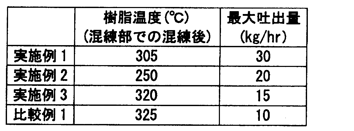
実施例1~3及び比較例1について、第1混練部81の混練後のポリスルホンの樹脂温度、最大吐出量を下表1に示す。
(実施例4)
図3は、実施例4で用いた押出機について、シリンダー2に設けられたヒーターを示す模式図である。なお、図3には、ヒーターに対する押出機が有する各構成の位置を、図1と共通した符号を用いて示している。
図3は、実施例4で用いた押出機について、シリンダー2に設けられたヒーターを示す模式図である。なお、図3には、ヒーターに対する押出機が有する各構成の位置を、図1と共通した符号を用いて示している。
押出機は、C0~C11まで各々独立に設定可能なヒーターが設けられたシリンダー2内に、モーターにて同方向に回転する2本のスクリュー(スクリュー径D:30mm、L2/D=42.6)が挿入され、上流側から、供給部4、第1ベント部51、追加部6及び第2ベント部52、が設けられた2軸押出機(池貝鉄工(株)製PCM30型)を用いた。
スクリューは、第1混練部81の長さ(L1)とスクリュー径(D)との比が1.67であり、第1混練部81のスクリュー構成が、上流側から順ニーディングディスク(5R)を3つ並べたもの、第2混練部82のスクリュー構成が、上流側から5順ニーディングディスク(5R)、ニュートラルニーディングディスク(5N)及び逆ニーディングディスク(5L)が組み合わせたもの、搬送部のスクリュー構成がフルフライトであるもの、を用いた。
スクリューの第1混練部81は、ヒーターC4と重なる位置(図では網掛けで示す)に配置され、第2混練部82は、ヒーターC9と重なる位置(図では網掛けで示す)に配置されている。
このような押出機を用い、供給部4からポリスルホン(スミカエクセル4100P、住友化学(株)製)を80重量部、追加部6からガラス繊維(オーエンスコーニング製、CS03JAPX-1)を20重量部供給して溶融混練を行い、ポリスルホンペレットを作製した。
押出条件は、シリンダーの各設定温度が、C0:280℃、C1~C4:320℃、C5~C11:340℃、ダイス:360℃、スクリュー回転数が200rpmであった。
また、真空ベントのゲージ圧が-0.08MPaとなるように保持した。
また、真空ベントのゲージ圧が-0.08MPaとなるように保持した。
(比較例2)
第1混練部81のスクリュー構成を、上流側から順ニーディングディスク(5R)、ニュートラルニーディングディスク(5N)及び逆ニーディングディスク(5L)を組み合わせた以外は、実施例1と同様にしてポリスルホンペレットを作製した。
第1混練部81のスクリュー構成を、上流側から順ニーディングディスク(5R)、ニュートラルニーディングディスク(5N)及び逆ニーディングディスク(5L)を組み合わせた以外は、実施例1と同様にしてポリスルホンペレットを作製した。
実施例4及び比較例2について、第1混練部81及び第2混練部82の混練後のポリスルホンの樹脂温度、最大吐出量を下表2に示す。

測定の結果、本発明の製造方法によれば、吐出量が多くなることが分かり、本発明の有用性が確かめられた。
本発明によれば、ポリスルホンの安定したストランドが得られ、ストランド、ひいてはポリスルホンペレットの生産性の向上を図ることが可能となるポリスルホンペレットの製造方法を提供することができる。
1…モーター、1a…モーターボックス、2…シリンダー、3…スクリュー、4…供給部、5…ベント部、6…追加部、7…搬送部、8…混練部、9…ストランドダイ、10…押出機、51…第1ベント部、52…第2ベント部、81…第1混練部、82…第2混練部、R…順ニーディングディスク、N…ニュートラルニーディングディスク、L…逆ニーディングディスク
Claims (10)
- ベント式の二軸押出機を用いるポリスルホンペレットの製造方法であって、
ここで、前記二軸押出機は、少なくとも、モーターと、シリンダーと、スクリューと、ストランドダイとを有し、
前記スクリューは、前記モーターに接続されて前記シリンダー内に挿入されており、前記ストランドダイは、前記シリンダーの最下流部に設置されており、
前記シリンダーが、少なくとも、原料のポリスルホンを供給する供給部と、シリンダー内のポリスルホンを加熱するヒーターと、前記シリンダー内で生じるガスを排出する1又は2以上のベント部と、を有し、
前記スクリューが、前記シリンダー内において前記供給部と前記ベント部との間に配置される1又は2以上の混練部を有しており、
最上流の前記ベント部の上流側に配置された前記混練部のうち、前記最上流のベント部に最も近い位置の前記混練部が、逆ニーディングディスクを用いないスクリュー構成であり、
前記ポリスルホンペレットの製造方法は、
原料のポリスルホンを前記供給部から供給すること、
前記ポリスルホンを加熱して溶融する第1の工程、
前記ポリスルホンを混練する第1の工程、
前記シリンダー内で発生したガスを前記ベント部から排出すること、
前記混練したポリスルホンを前記ストランドダイから押し出してストランドを形成すること、及び
前記ストランドを切断してペレット化すること、を含む前記ポリスルホンペレットの製造方法。 - 前記ポリスルホンを加熱して溶融する第1の工程及び前記ポリスルホンを混練する第1の工程が前記最上流のベント部に最も近い位置の混錬部で行われ、混練された後のポリスルホンの樹脂温度が、ポリスルホンの流動開始温度以下となるよう加熱する、請求項1に記載のポリスルホンペレットの製造方法。
- 前記最上流のベント部に最も近い位置の混練部が、順ニーディングディスクで構成されたスクリュー構成であり、前記ポリスルホンを加熱して溶融する第1の工程及び前記ポリスルホンを混練する第1の工程が順ニーディングディスクで構成されたスクリュー構成である混練部で行われることを含む、請求項1に記載のポリスルホンペレットの製造方法。
- 前記混錬部の長さ(L1)とスクリュー径(D)との比(L1/D)が、0.5~5である、請求項1に記載のポリスルホンペレットの製造方法。
- スクリュー長さ(L2)とスクリュー径(D)との比(L2/D)が、25以上である、請求項1に記載のポリスルホンペレットの製造方法。
- 前記二軸押出機は、前記ベント部が、最上流に設けられた第1ベント部と、前記第1ベント部の下流側に設けられた第2ベント部と、を含み、
前記混練部が、前記シリンダー内において前記供給部と前記第1ベント部との間に配置される第1混練部と、前記第1ベント部と前記第2ベント部との間に配置される第2混練部と、を含み、
前記シリンダーが、前記第1ベント部と、前記シリンダー内において前記第2混練部が配置される位置と、の間に設けられた追加部を有しており、
前記ポリスルホンペレットの製造方法が、
前記ポリスルホンを加熱して溶融する第2の工程、
前記ポリスルホンに添加する成分を前記追加部から供給すること、
前記ポリスルホンを加熱して溶融する第2の工程、及び
前記ポリスルホンを混練する第2の工程、を更に含み、
ここで、前記ポリスルホンを加熱して溶融する第2の工程及び前記ポリスルホンを混練する第2の工程が、前記第2混練部で行われ、前記第2混練部で混練された後のポリスルホンの樹脂温度が、ポリスルホンの流動開始温度以上となるように加熱する、請求項1に記載のポリスルホンペレットの製造方法。 - 前記追加部から供給する成分が、繊維状フィラーである、請求項6に記載のポリスルホンペレットの製造方法。
- 原料のポリスルホンの平均粒径が1000μm以下である、請求項1に記載のポリスルホンペレットの製造方法。
- 原料のポリスルホンがポリスルホン組成物である、請求項1に記載のポリスルホンペレットの製造方法。
- 前記シリンダー内で発生したガスを前記第2ベント部から排出することを更に含む、請求項6に記載のポリスルホンペレットの製造方法。
Applications Claiming Priority (2)
| Application Number | Priority Date | Filing Date | Title |
|---|---|---|---|
| JP2011059473A JP2012192677A (ja) | 2011-03-17 | 2011-03-17 | ポリスルホンペレットの製造方法 |
| JP2011-059473 | 2011-03-17 |
Publications (1)
| Publication Number | Publication Date |
|---|---|
| WO2012124762A1 true WO2012124762A1 (ja) | 2012-09-20 |
Family
ID=46830827
Family Applications (1)
| Application Number | Title | Priority Date | Filing Date |
|---|---|---|---|
| PCT/JP2012/056675 Ceased WO2012124762A1 (ja) | 2011-03-17 | 2012-03-15 | ポリスルホンペレットの製造方法 |
Country Status (3)
| Country | Link |
|---|---|
| JP (1) | JP2012192677A (ja) |
| TW (1) | TW201249627A (ja) |
| WO (1) | WO2012124762A1 (ja) |
Cited By (6)
| Publication number | Priority date | Publication date | Assignee | Title |
|---|---|---|---|---|
| CN103722634A (zh) * | 2013-12-27 | 2014-04-16 | 马鞍山市秋枫工程塑料异型材料制造有限责任公司 | 一种旋转碰撞的塑料造粒设备及其造粒方法 |
| EP2813334A4 (en) * | 2012-02-07 | 2015-07-22 | Mitsubishi Rayon Co | RESIN BLEND PROCESS |
| JP2016107611A (ja) * | 2014-12-08 | 2016-06-20 | 三菱エンジニアリングプラスチックス株式会社 | ポリカーボネート樹脂組成物の製造方法 |
| JP2021172681A (ja) * | 2020-04-20 | 2021-11-01 | 住友化学株式会社 | 樹脂成形体の製造方法 |
| CN115674627A (zh) * | 2022-11-02 | 2023-02-03 | 归中智能装备(南通)有限公司 | 一种极性成膜设备及成膜方法 |
| US12232737B2 (en) | 2016-03-17 | 2025-02-25 | Eclipse Medical Limited | Occluding anatomical structures |
Citations (5)
| Publication number | Priority date | Publication date | Assignee | Title |
|---|---|---|---|---|
| JPH09296117A (ja) * | 1994-04-21 | 1997-11-18 | Lion Corp | 導電性熱可塑性樹脂組成物の製造方法 |
| JP2000095863A (ja) * | 1998-09-25 | 2000-04-04 | Sumitomo Chem Co Ltd | 熱可塑性芳香族ポリスルホン樹脂 |
| JP2002210731A (ja) * | 2001-01-16 | 2002-07-30 | Kobe Steel Ltd | 二軸連続混練機とこれによる混練方法 |
| JP2004276598A (ja) * | 2003-02-24 | 2004-10-07 | Sumika Color Kk | 熱可塑性樹脂ペレットの製造方法 |
| JP2009203410A (ja) * | 2008-02-29 | 2009-09-10 | Toray Ind Inc | 熱可塑性樹脂組成物およびその製造方法 |
Family Cites Families (4)
| Publication number | Priority date | Publication date | Assignee | Title |
|---|---|---|---|---|
| JPH0929738A (ja) * | 1995-07-18 | 1997-02-04 | Mitsubishi Gas Chem Co Inc | ポリカーボネート樹脂成形材料の製造法 |
| JP3782186B2 (ja) * | 1997-01-08 | 2006-06-07 | 旭化成ケミカルズ株式会社 | 押出方法 |
| JP4330490B2 (ja) * | 2004-05-27 | 2009-09-16 | カルプ工業株式会社 | 二軸連続式混練装置を用いた圧縮タルクを含む熱可塑性樹脂組成物の製造方法 |
| JP2008238626A (ja) * | 2007-03-28 | 2008-10-09 | Toray Ind Inc | 熱可塑性樹脂組成物の製造方法 |
-
2011
- 2011-03-17 JP JP2011059473A patent/JP2012192677A/ja active Pending
-
2012
- 2012-03-15 WO PCT/JP2012/056675 patent/WO2012124762A1/ja not_active Ceased
- 2012-03-16 TW TW101109111A patent/TW201249627A/zh unknown
Patent Citations (5)
| Publication number | Priority date | Publication date | Assignee | Title |
|---|---|---|---|---|
| JPH09296117A (ja) * | 1994-04-21 | 1997-11-18 | Lion Corp | 導電性熱可塑性樹脂組成物の製造方法 |
| JP2000095863A (ja) * | 1998-09-25 | 2000-04-04 | Sumitomo Chem Co Ltd | 熱可塑性芳香族ポリスルホン樹脂 |
| JP2002210731A (ja) * | 2001-01-16 | 2002-07-30 | Kobe Steel Ltd | 二軸連続混練機とこれによる混練方法 |
| JP2004276598A (ja) * | 2003-02-24 | 2004-10-07 | Sumika Color Kk | 熱可塑性樹脂ペレットの製造方法 |
| JP2009203410A (ja) * | 2008-02-29 | 2009-09-10 | Toray Ind Inc | 熱可塑性樹脂組成物およびその製造方法 |
Cited By (10)
| Publication number | Priority date | Publication date | Assignee | Title |
|---|---|---|---|---|
| EP2813334A4 (en) * | 2012-02-07 | 2015-07-22 | Mitsubishi Rayon Co | RESIN BLEND PROCESS |
| US9108171B2 (en) | 2012-02-07 | 2015-08-18 | Mitsubishi Rayon Co., Ltd. | Method of manufacturing resin kneaded product |
| CN103722634A (zh) * | 2013-12-27 | 2014-04-16 | 马鞍山市秋枫工程塑料异型材料制造有限责任公司 | 一种旋转碰撞的塑料造粒设备及其造粒方法 |
| CN105128167A (zh) * | 2013-12-27 | 2015-12-09 | 马鞍山市秋枫工程塑料异型材料制造有限责任公司 | 一种旋转碰撞的塑料造粒设备的造粒方法 |
| CN103722634B (zh) * | 2013-12-27 | 2016-01-20 | 马鞍山市秋枫工程塑料异型材料制造有限责任公司 | 一种旋转碰撞的塑料造粒设备及其造粒方法 |
| JP2016107611A (ja) * | 2014-12-08 | 2016-06-20 | 三菱エンジニアリングプラスチックス株式会社 | ポリカーボネート樹脂組成物の製造方法 |
| US12232737B2 (en) | 2016-03-17 | 2025-02-25 | Eclipse Medical Limited | Occluding anatomical structures |
| JP2021172681A (ja) * | 2020-04-20 | 2021-11-01 | 住友化学株式会社 | 樹脂成形体の製造方法 |
| JP7514105B2 (ja) | 2020-04-20 | 2024-07-10 | 住友化学株式会社 | 樹脂成形体の製造方法 |
| CN115674627A (zh) * | 2022-11-02 | 2023-02-03 | 归中智能装备(南通)有限公司 | 一种极性成膜设备及成膜方法 |
Also Published As
| Publication number | Publication date |
|---|---|
| TW201249627A (en) | 2012-12-16 |
| JP2012192677A (ja) | 2012-10-11 |
Similar Documents
| Publication | Publication Date | Title |
|---|---|---|
| JP6128299B2 (ja) | 液晶ポリエステル組成物の製造方法 | |
| WO2012124762A1 (ja) | ポリスルホンペレットの製造方法 | |
| CN103009595B (zh) | 生产树脂组合物的方法 | |
| CN106243646B (zh) | 液晶聚酯组合物及成形体 | |
| CN1774325B (zh) | 聚合物树脂共混物及其制造方法 | |
| CN109071800B (zh) | 增容的聚合物组合物 | |
| CN108291083A (zh) | 用于积层制造的无定形聚芳醚酮及其共混物 | |
| JP5348925B2 (ja) | フィルムの製造方法及びフィルム | |
| CN111334895B (zh) | 3d打印耐热支撑材料 | |
| KR102352873B1 (ko) | 3d 인쇄 내열성 지지 재료 | |
| JP2012206296A (ja) | 液晶ポリエステル組成物の製造方法 | |
| CN104066559A (zh) | 树脂组合物的制造方法 | |
| JP2008238626A (ja) | 熱可塑性樹脂組成物の製造方法 | |
| CN102234425A (zh) | 热塑性树脂组合物的制备方法 | |
| JP2015030132A (ja) | サイドフィーダー、それを有する押出機、および押出機を用いた押出方法 | |
| CN102321369A (zh) | 低密度聚芳硫醚复合材料及其制备方法 | |
| CN107428060B (zh) | 聚酯薄膜及其制造方法、太阳能电池用背面保护片、以及太阳能电池模块 | |
| EP3448935A1 (en) | Compatibilized polymer compositions | |
| JP7487000B2 (ja) | 樹脂組成物及び樹脂成形体 | |
| JP6495679B2 (ja) | ポリアリーレンスルフィド樹脂組成物 | |
| JP7514105B2 (ja) | 樹脂成形体の製造方法 | |
| WO2017186923A1 (en) | Compatibilized polymer compositions | |
| CN117377723A (zh) | 树脂组合物、其制造方法和成形体 | |
| EP4039747B1 (en) | Resin composition, film, composite material, movable body, and material for three-dimensional shaping use | |
| WO2022209940A1 (ja) | ペレット |
Legal Events
| Date | Code | Title | Description |
|---|---|---|---|
| 121 | Ep: the epo has been informed by wipo that ep was designated in this application |
Ref document number: 12757206 Country of ref document: EP Kind code of ref document: A1 |
|
| NENP | Non-entry into the national phase |
Ref country code: DE |
|
| 122 | Ep: pct application non-entry in european phase |
Ref document number: 12757206 Country of ref document: EP Kind code of ref document: A1 |