WO2012124591A1 - 信号処理装置、制御プログラム、および集積回路 - Google Patents
信号処理装置、制御プログラム、および集積回路 Download PDFInfo
- Publication number
- WO2012124591A1 WO2012124591A1 PCT/JP2012/055934 JP2012055934W WO2012124591A1 WO 2012124591 A1 WO2012124591 A1 WO 2012124591A1 JP 2012055934 W JP2012055934 W JP 2012055934W WO 2012124591 A1 WO2012124591 A1 WO 2012124591A1
- Authority
- WO
- WIPO (PCT)
- Prior art keywords
- signal
- sharpening
- frequency
- input
- vertical
- Prior art date
- Legal status (The legal status is an assumption and is not a legal conclusion. Google has not performed a legal analysis and makes no representation as to the accuracy of the status listed.)
- Ceased
Links
Images









Classifications
-
- G—PHYSICS
- G06—COMPUTING OR CALCULATING; COUNTING
- G06T—IMAGE DATA PROCESSING OR GENERATION, IN GENERAL
- G06T5/00—Image enhancement or restoration
- G06T5/73—Deblurring; Sharpening
-
- H—ELECTRICITY
- H04—ELECTRIC COMMUNICATION TECHNIQUE
- H04N—PICTORIAL COMMUNICATION, e.g. TELEVISION
- H04N5/00—Details of television systems
- H04N5/14—Picture signal circuitry for video frequency region
- H04N5/142—Edging; Contouring
Definitions
- the present invention relates to a signal processing device or the like that improves image quality by sharpening an image.
- contour compensation is performed to make the rise and fall of an image signal corresponding to the contour portion of an image displayed on the own device steep.
- This contour compensation is performed by extracting a high frequency component of an image signal (luminance signal) input to a display of a television receiver and adding the extracted high frequency component to the input image signal. Done.
- the frequency characteristics of the image signal that deteriorates due to processing performed in each circuit in the television receiver is improved, and the apparent image quality is improved.
- Patent Literature 1 There is a technique disclosed in Patent Literature 1 as a technique related to image sharpening.
- the technique disclosed in Patent Document 1 is a technique related to an image processing apparatus that performs high-resolution processing suitable for each region.
- JP 2009-70123 A publication date: April 2, 2009
- the frequency component in the vicinity of the Nyquist frequency fs / 2 which is a half of the sampling frequency fs, increases, but the Nyquist frequency fs / 2 is increased.
- High frequency components exceeding that is, high frequency components not included in the image signal to be processed
- the image quality cannot be sufficiently improved particularly when an image is enlarged.
- the resolution of a high-definition television (HDTV: High Definition Television) (1080 ⁇ 1920 pixel full high-definition) television receiver that is displayed on a conventional analog television or the like is half that of full high-definition television.
- HDTV High Definition Television
- the image signal after the enlargement process is in the vicinity of the Nyquist frequency Fbs / 2.
- the enlarged image is displayed in a blurred manner.
- a high frequency component exceeding the Nyquist frequency fs / 2 that is, a high frequency component not included in the image signal to be processed. It can.
- the degree of sharpening is increased, such high frequency components are increased, which may cause distortion. Therefore, the sharpening degree cannot be increased sufficiently.
- the moving region is extracted and the extracted region is replaced with an image with less blur.
- the motion region may be extracted erroneously. Even if the image is replaced with a less blurred image, it does not use a frequency component higher than the Nyquist frequency (that is, a high frequency component not included in the image signal to be processed), so that the image quality is sufficiently improved. I can't.
- the present invention has been made in view of the above problems, and an object of the present invention is to provide a signal processing device, a control program, and an integrated circuit capable of highly sharpening an image with a simple configuration. It is in.
- a signal processing apparatus performs a process of sharpening the image on an input signal representing an image, and outputs an output signal representing the sharpened image.
- a signal interpolating means for generating a post-interpolation signal by interpolating the signal to increase the sampling frequency with respect to the input signal, and the high-frequency in the post-interpolation signal using the post-interpolation signal as an input
- Sharpening means for generating a sharpening signal obtained by monotonically increasing the non-linear frequency component in a broad sense, and outputting the sharpening signal as the output signal.
- An integrated circuit is an integrated circuit that performs processing for sharpening the image on an input signal representing an image and outputs an output signal representing the sharpened image, the input signal representing the image
- a signal interpolation circuit that generates an interpolated signal by interpolating the signal to increase the sampling frequency and the post-interpolation signal as inputs, and the high-frequency components in the post-interpolation signal are non-linearly broadly defined.
- a sharpening circuit that generates a sharpened signal that is monotonously increased, and outputs the sharpened signal as the output signal.
- the interpolated signal is generated by interpolating the signal to increase the sampling frequency with respect to the input signal. That is, the input signal is oversampled to generate an interpolated signal. Then, a sharpening signal is generated by monotonically increasing the high-frequency component in the post-interpolation signal in a non-linear and broad sense, and the sharpening signal is output as an output signal.
- the process of “increasing monotonously in a broad sense in a non-linear manner” is a non-linear process such as a power operation. Therefore, by increasing the high-frequency component of the post-interpolation signal in a non-linear and broad sense, the high-frequency component not included in the post-interpolation signal is added to the post-interpolation signal.
- a frequency component near and higher than the Nyquist frequency which is a half of the sampling frequency when the post-interpolation signal is discretized, is added to the post-interpolation signal. This sharpens the rise and fall of the interpolated signal and sharpens the image. Note that in the process of performing a linear operation on the post-interpolation signal, a high frequency region exceeding the Nyquist frequency cannot be compensated.
- the frequency component in the high frequency region is used. Therefore, if sharpening is increased, the frequency component may be distorted. Therefore, in order to prevent distortion, it is necessary to suppress the amount of frequency components to be added, and as a result, the degree of sharpening cannot be increased.
- the high-frequency component in the input signal is a mid-range or low-frequency component in the post-interpolation signal, and therefore processing is performed to monotonously increase the high-frequency component in the post-interpolation signal in a non-linear and broad sense.
- a filter that extracts a high-frequency component near the Nyquist frequency of the input signal usually requires a large number of taps.
- a filter that extracts a frequency component in the middle band or low band of the post-interpolation signal needs only a smaller number of taps than a filter that extracts a high-frequency component. That is, in the case of generating a sharpening signal that is monotonically increased in a non-linear and broad sense with respect to the high frequency components in the post-interpolation signal, it is possible to reduce the size and cost of the apparatus and reduce the processing load. There is an effect that can be done.
- the signal processing device and the integrated circuit according to the present invention it is possible to sharpen an image more strongly (strongly) than before and greatly improve image quality and a sense of resolution, and to reduce the size, There is an effect that the cost can be reduced and the processing load can be reduced.
- the signal processing device is a signal processing device that performs the process of sharpening the image on the input signal representing the image and outputs the output signal representing the sharpened image.
- a signal interpolating means for generating a post-interpolation signal by interpolating the signal to increase the sampling frequency with respect to the input signal, and a high frequency component in the post-interpolation signal using the post-interpolation signal as input.
- Sharpening means for generating a sharpening signal obtained by monotonically increasing non-linearly in a broad sense, and outputting the sharpening signal as the output signal.
- An integrated circuit is an integrated circuit that performs processing for sharpening the image on an input signal representing an image and outputs an output signal representing the sharpened image, the input signal representing the image
- a signal interpolation circuit that generates an interpolated signal by interpolating the signal to increase the sampling frequency and the post-interpolation signal as inputs, and the high-frequency components in the post-interpolation signal are non-linearly broadly defined.
- a sharpening circuit that generates a sharpened signal that is monotonously increased, and outputs the sharpened signal as the output signal.
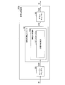
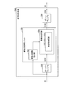
- FIG. 2A is a block diagram showing another schematic configuration of the signal processing apparatus according to the present invention.
- FIG. 2B is a block diagram showing still another schematic configuration of the signal processing apparatus according to the present invention.
- FIG. 3A is a schematic diagram illustrating an example of a frequency spectrum of an input signal input to the signal processing apparatus illustrated in FIGS. 1 and 2.
- FIG. 3B shows an oversampling signal obtained by doubling the sampling frequency of the input signal having the frequency spectrum shown in FIG. 3A by the oversampler of the signal processing apparatus shown in FIG.
- FIG. 3C shows an example of a frequency spectrum.
- the oversampling signal having the frequency spectrum shown in FIG. 3B is subjected to a sharpening process by the sharpening unit of the signal processing apparatus shown in FIGS.
- FIG. 3D shows a down-sampled signal obtained by halving the sharpened signal having the frequency spectrum shown in FIG. 3C by the down sampler of the signal processing apparatus shown in FIG.
- FIG. 3D shows a down-sampled signal obtained by halving the sharpened signal having the frequency spectrum shown in FIG. 3C by the down sampler of the signal processing apparatus shown in FIG.
- FIG. 3D shows a down-sampled signal obtained by halving the sharpened signal having the frequency spectrum shown in FIG. 3C by the down sampler of the signal processing apparatus shown in FIG.
- FIG. 3D shows a down-sampled signal obtained by halving the sharpened signal having the frequency spectrum shown in FIG. 3C by the down sampler of the signal processing apparatus shown in FIG.
- FIG. 3E is a schematic diagram illustrating an example of a frequency spectrum of a signal obtained by performing a sharpening process using a linear operation on the oversampling signal having the frequency spectrum illustrated in FIG.
- FIG. 3F shows a sharpening processing unit of the signal processing apparatus shown in FIGS. 1 and 2 without oversampling the input signal having the frequency spectrum shown in FIG.
- It is a schematic diagram which shows an example of the frequency spectrum of the signal obtained by giving sharpening strongly by (3).
- It is a block diagram which shows the structure of the signal processing apparatus which concerns on one Embodiment of this invention.
- It is a block diagram which shows the structure of the sharpening process part contained in the signal processing apparatus shown in FIG.
- FIG. 8B is a diagram schematically showing the waveform of the high-frequency signal generated by the sharpening processing unit shown in FIG.
- FIG. 8C is a diagram schematically illustrating the waveform of the nonlinear signal generated by the sharpening processing unit illustrated in FIG.
- FIG. 8D is a diagram schematically showing the waveform of the code conversion signal generated by the sharpening processing unit shown in FIG. FIG.
- FIG. 9A is a diagram schematically illustrating a waveform of a signal input to the sharpening processing unit illustrated in FIG.
- FIG. 9B is a diagram schematically showing a waveform obtained by enhancing the signal shown in FIG. 9A with the prior art.
- It is a block diagram which shows the other structure of the sharpening process part contained in the signal processing apparatus which concerns on this invention.
- It is a block diagram which shows the structure of the differentiation part contained in the sharpening process part shown in FIG. (A) of FIG. 12 is a figure which shows typically the waveform of the signal input into the sharpening process part shown in FIG. FIG.
- FIG. 12B is a diagram schematically showing the waveform of the high-frequency signal generated by the sharpening processing unit shown in FIG.
- FIG. 12C is a diagram schematically showing the waveform of the nonlinear signal generated by the sharpening processing unit shown in FIG. (D) of FIG. 12 is a figure which shows typically the waveform of the differential signal produced
- FIG. 14 is a figure which shows typically the waveform of the signal input into the sharpening process part shown in FIG.
- FIG. 14B schematically shows the waveform of the high-frequency signal generated by the sharpening processing unit shown in FIG.
- FIG. 14C is a diagram schematically showing the waveform of the nonlinear signal generated by the sharpening processing unit shown in FIG.
- FIG. 14D is a diagram schematically illustrating a waveform of an output signal generated by the sharpening processing unit illustrated in FIG. It is a block diagram which shows the further another structure of the sharpening process part contained in the signal processing apparatus which concerns on this invention.
- FIG. 19A is a block diagram showing a configuration of a signal processing device according to still another embodiment of the present invention.
- FIG. 19B is a block diagram showing another configuration of the signal processing apparatus according to the embodiment of the present invention. It is a block diagram which shows the structure of the signal processing apparatus which concerns on another one Embodiment of this invention.
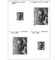
- FIG. 22A is a diagram illustrating an example of an original image represented by an input signal SR.
- FIG. 22B is a diagram illustrating an example of an image represented by an oversampling signal obtained from the input signal representing the image illustrated in FIG. 22A via the oversampler.
- FIG. 22C shows an example of an image represented by a sharpening signal obtained from the oversampling signal representing the image shown in FIG. 22B through the sharpening processing unit shown in FIG.
- FIG. 22D is a diagram illustrating an example of an image represented by a down-sampling signal obtained from the sharpening signal representing the image illustrated in FIG. 22C through the down sampler.
- the signal processing apparatus (integrated circuit) 500 performs oversampling on a digital signal representing an image (hereinafter also referred to as an image signal), and then sharpens the image. It is the apparatus which performs the sharpening process for.
- the sharpening process performed by the signal processing device 500 signal processing using nonlinear calculation is performed on the high-frequency component of the input signal. Therefore, the sharpening process performed by the signal processing device 500 adds a high-frequency component that cannot be used in the sharpening process using linear calculation to the image signal. Details of the sharpening process performed by the signal processing apparatus 500 will be described later.
- signal processing device 500 an image signal input to the signal processing device 500 is referred to as an input signal SR.
- An image signal output from the signal processing device 500 is denoted as an output signal SO.
- FIGS. 1 and 2 are block diagrams showing a schematic configuration of the signal processing device 500.
- the signal processing apparatus 500 includes at least an oversampler (signal interpolation means, signal interpolation circuit) 200 and a sharpening processing unit (sharpening means, sharpening circuit) 100.
- a downsampler (signal thinning means) 300 may be provided. Whether or not the down sampler 300 is provided depends on the angle of view of the image represented by the output signal SO as described above.
- a configuration including a high frequency removal filter (high frequency removal means) 350 may be used.
- the oversampler 200 performs oversampling (interpolation) on the input signal SR in order to increase the sampling frequency of the input signal SR.
- the oversampler 200 outputs a signal obtained by multiplying the sampling frequency of the input signal SR by J (J is an arbitrary integer equal to or greater than 2).
- a signal output from the oversampler 200 is referred to as an oversampling signal S200 (post-interpolation signal).
- the sharpening processing unit 100 is provided in the subsequent stage of the oversampler 200.
- the sharpening processing unit 100 performs sharpening by performing signal processing using a non-linear operation on high frequency components in the oversampling signal S200.
- a signal is generated by monotonously increasing non-linearly broadly the high frequency components in the oversampling signal S200.
- a signal in which a high frequency component not included in the oversampling signal S200 is added to the oversampling signal S200 is output.
- a signal obtained by adding to the oversampling signal S200 a frequency component in the vicinity of the Nyquist frequency that is 1 ⁇ 2 the sampling frequency in the case of discretizing the oversampling signal S200 and higher than the Nyquist frequency is output.
- the sharpening processing unit 100 sharpens the rising and falling edges of the oversampling signal S200.
- a signal output from the sharpening processing unit 100 is referred to as a sharpening signal S100.
- the sharpening signal S100 becomes the output signal SO.
- the sharpening processing unit 100 may be anything as long as it includes a configuration that performs signal processing using a non-linear operation on the high-frequency component of the oversampling signal S200.
- a configuration including the sharpening processing unit 100A is most preferable.
- the down sampler 300 is provided in the subsequent stage of the sharpening processing unit 100.
- the downsampler 300 performs downsampling (decimation) on the sharpening signal S100 in order to lower the sampling frequency of the sharpening signal S100.
- the down sampler 300 outputs a signal obtained by multiplying the sampling frequency of the sharpening signal S100 by 1 / K (K is an arbitrary integer of 2 or more).
- a signal output from the down sampler 300 is referred to as a down sampling signal S300.
- the downsampling signal S300 becomes the output signal SO.
- the high-frequency removal filter 350 is provided in the subsequent stage of the sharpening processing unit 100 and in the previous stage of the downsampler 300.
- the high-frequency removal filter 350 is a generally known low-pass filter and removes high-frequency components of the sharpening signal S100. Any filter may be used as long as it removes a predetermined high-frequency component included in the sharpening signal S100. Further, it may be a one-dimensional filter or a two-dimensional filter. It is assumed that the frequency characteristic of the high-frequency removal filter 350 is appropriately adjusted by the filter coefficient. The reason why the high-frequency removal filter 350 is provided will be described later.
- the high-frequency removal filter 350 may be provided integrally with the sharpening processing unit 100 or may be provided integrally with the down sampler 300.
- an image represented by the input signal SR may be a still image or a moving image.
- the moving image is displayed in real time on, for example, a standard definition television (SDTV: Standard Definition Television) or a high-definition television (HDTV) receiver. It is assumed that the moving image is composed of a plurality of temporally continuous frames (screens).
- the input signal SR will be described as being constituted by a data string (series of pixel values) composed of pixel values of pixels arranged adjacent to each other in the horizontal direction of the image, but is arranged adjacent to each other in the vertical direction of the image. You may be comprised by the data sequence which consists of the pixel value of a pixel.
- FIG. 3 is a schematic diagram illustrating an example of a frequency spectrum of a signal handled by each unit of the signal processing device.
- FIGS. 3A to 3F there is no signal in the high frequency band, but there is actually a very small value signal.
- FIG. 3A is a schematic diagram showing an example of a frequency spectrum of the input signal SR.
- the sampling frequency is expressed as fs.
- FIG. 3B shows the frequency spectrum of the oversampling signal S200 obtained by doubling the sampling frequency of the input signal SR having the frequency spectrum shown in FIG. It is a schematic diagram which shows an example.
- Fbs 2fs.
- there is a frequency component between the Nyquist frequency fs / 2 with respect to the sampling frequency fs of the input signal SR and the Nyquist frequency Fbs / 2 ( fs) with respect to the new sampling frequency Fbs. not exist.
- FIG. 3C shows a sharpening signal obtained by sharpening the oversampling signal S200 having the frequency spectrum shown in FIG. 3B by the sharpening processing unit 100.
- It is a schematic diagram which shows an example of the frequency spectrum of S100.
- a high frequency component in the vicinity of the Nyquist frequency fs / 2 (and in the vicinity of 3 fs / 2) is added to the frequency spectrum. That is, a high frequency component not included in the input signal SR is added.
- the reason why the high-frequency component not included in the input signal SR is added is because nonlinear calculation is used in the sharpening processing by the sharpening processing unit 100.
- FIG. 3D shows the frequency spectrum of the down-sampled signal S300 obtained by halving the sharpening signal S100 having the frequency spectrum shown in FIG.
- the sampling frequency of the downsampling signal S300 is fs.
- the high frequency component in the vicinity of the Nyquist frequency fs / 2 is increased as compared with the frequency spectrum shown in (a) of FIG. Therefore, the image represented by the downsampling signal S300 having the frequency spectrum shown in FIG. 3D is more than the original image represented by the input signal SR having the frequency spectrum shown in FIG.
- the rise and fall of the signal corresponding to the contour portion (edge) included in the image is made steeper.
- the image represented by the downsampling signal S300 is sharper than the original image represented by the input signal SR, and the image quality is greatly improved.
- FIG. 3E shows an example of a frequency spectrum of a signal obtained by performing a sharpening process using a linear operation on the oversampling signal S200 having the frequency spectrum shown in FIG. It is a schematic diagram.
- the frequency spectrum shown in (e) of FIG. 3 is different from the frequency spectrum shown in (c) of FIG. 3, although the high frequency component included in the input signal SR is increased by the sharpening process. High frequency components not included in the above are not added. Therefore, compared with the sharpening by the sharpening processing unit 100, the degree of sharpening is small.
- filter A a filter that extracts the high-frequency component
- An example of the filter B is a filter 110 provided in a sharpening processing unit 100A described later.
- the sharpening processing unit 100 since there is no frequency component between fs / 2 and 3fs / 2, sharpening processing by the sharpening processing unit 100 is performed. However, it is possible to sufficiently add a high frequency component without causing distortion. Therefore, the sharpening degree can be sufficiently increased. That is, the original image can be highly sharpened.
- the sharpening signal S100 output from the sharpening processing unit 100 when the sharpening signal S100 output from the sharpening processing unit 100 includes a frequency component exceeding fs / 2 and a frequency component lower than 3fs / 2, the downsampler 300 reduces the frequency.
- the downsampling signal S300 may be distorted in the vicinity of the Nyquist frequency fs / 2. Therefore, when the signal processing apparatus 500 includes the down sampler 300, the sharpening processing unit 100 preferably removes frequency components that cause distortion from the sharpening signal S100. That is, the signal processing device 500 is preferably configured to include a high-frequency removal filter 350 as shown in FIG. According to this configuration, since the downsampling is performed after the frequency component causing the distortion is removed, the occurrence of distortion in the downsampling signal S300 can be suppressed.
- the signal processing device 500 needs to include the downsampler 300 is determined according to the angle of view of the image represented by the output signal SO. For example, an input signal SR for high-definition television (HDTV) is oversampled by the oversampler 200 to obtain a signal for a display (so-called 4K display) having a number of pixels of about 4000 ⁇ 2000, When the signal processing device 500 performs the sharpening process and outputs the sharpened signal S100 after the sharpening process to the 4K display as it is, the downsampler 300 is not necessary.
- HDTV high-definition television
- the downsampler 300 if it is necessary to output the output signal SO after lowering the sampling frequency of the sharpening signal S100, the downsampler 300 must be provided. For example, when the angle of view of the image represented by the input signal SR and the angle of view of the image represented by the output signal SO are made the same, the downsampler 300 having the same downsample ratio as the oversample ratio by the oversampler 200 is provided. .
- the input signal SR is a signal for standard definition television (SDTV: Standard Definition Television) (horizontal pixel number: 720), and the output signal SO is a high definition television (HDTV) (horizontal pixel number). : 1920)
- SDTV Standard Definition Television
- HDTV high definition television
- the input signal SR is oversampled to a signal having a horizontal pixel number of 5670 which is the least common multiple of 720 and 1920, and then the signal processing device 500 performs a sharpening process on the signal and Sampling is performed to obtain an output signal SO.
- oversampling and downsampling may be performed in the time direction.
- a system of 60 fields (30 frames) / second is used in Japan and the United States, and a system of 50 fields (25 frames) / second is used in Europe. Therefore, when switching between the input signal SR and the output signal SO between them, the input signal SR is oversampled to a signal of 300 fields / second which is the least common multiple of 60 and 50, and then the signal is A sharpening process is performed by the signal processing device 500, downsampling is performed to obtain an output signal SO.
- Embodiment 1 One embodiment of the present invention will be described below with reference to FIGS. Note that the signal processing device 500 according to the present embodiment is referred to as a signal processing device 500a.
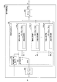
- FIG. 4 is a block diagram illustrating a configuration of the signal processing device 500a.
- the signal processing device 500a includes at least an oversampler 200 and a sharpening processing unit (sharpening means, horizontal side sharpening means, vertical side sharpening means, time side sharpening means) 100A.
- a sharpening processing unit 100 is also shown in the figure.
- a down sampler 300 may be provided. Whether or not the down sampler 300 is provided depends on the angle of view of the image represented by the output signal SO as described above.
- the high region removal filter 350 may be provided.
- the sharpening processing unit 100A includes configuration examples of the sharpening processing units 100a to 100e described later, and any of them may be used. In this specification, when the sharpening processing units 100a to 100e are not distinguished, they are simply expressed as “sharpening processing unit 100A”.
- the sharpening processing unit 100A performs a sharpening process for sharpening the waveform on the signal input to the sharpening processing unit 100A, and outputs the sharpened signal.
- the sharpening process is a process of sharpening (enhancing) the rise and fall of a signal corresponding to a contour portion (edge) included in an image represented by an input signal.
- a signal input to the sharpening processing unit 100A is also referred to as an input signal Sin.
- a signal output from the sharpening processing unit 100A is also referred to as an output signal Sout.
- the sharpening processing unit 100A includes at least a non-linear processing unit (non-linear processing means, horizontal non-linear processing means, vertical non-linear processing means, time-side non-linear processing means) 102 that performs non-linear calculation. Yes.
- non-linear processing units 102a to 102e described later are simply expressed as “non-linear processing unit 102”.
- the sharpening processing unit 100A may include a high-frequency component not included in the input signal Sin in the output signal Sout by performing a non-linear operation in the non-linear processing unit 102 on the high-frequency component of the input signal Sin. it can. Therefore, when sharpening processing is performed by the sharpening processing unit 100A, the rising and falling edges of the input signal Sin can be made steeper as compared with the sharpening processing using linear calculation.
- the output signal Sout is also expressed as a harmonic of the input signal Sin.
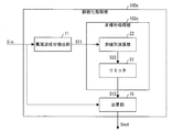
- FIG. 5 is a block diagram illustrating a configuration of the sharpening processing unit 100a.
- the sharpening processing unit 100a includes a high frequency component extracting unit (low frequency component removing unit, horizontal side low frequency component removing unit, vertical side low frequency component removing unit, time side low frequency component removing unit) 11, A nonlinear processing unit 102a and an adding unit (adding unit, horizontal side adding unit, vertical side adding unit, time side adding unit) 15 are provided.
- the high-frequency component extraction unit 11 generally extracts a high-frequency component included in the input signal Sin, and outputs a high-frequency signal S11 (low-frequency removal signal, horizontal-side low-frequency removal signal, vertical-side low-frequency removal signal, time-side low). Output as a frequency elimination signal).
- the configuration of the high frequency component extraction unit 11 will be described with reference to FIG.
- FIG. 6 is a block diagram showing the configuration of the high frequency component extraction unit 11.
- the high-frequency component extracting unit 11 includes a filter 110, a rounding processing unit (low level signal removing unit) 132, and a limiter (high level signal removing unit) 133.
- each of the unit delay elements 111h is configured to output the image represented by the input signal.
- a signal that is delayed by a unit time in the horizontal direction that is, a signal that represents a group of pixels that are arranged adjacent to each other in the horizontal direction of the image represented by the input signal
- each of the unit delay elements 111h is configured to display the image represented by the input signal.
- a signal delayed by unit time in the vertical direction (that is, a signal representing a pixel group consisting of pixels arranged adjacent to each other in the vertical direction of the image represented by the input signal) is output.
- each of the unit delay elements 111h is a unit in the time direction of the image represented by the input signal.
- a signal delayed by time (that is, a signal representing a pixel group composed of pixels arranged adjacent to each other in the time direction of the image represented by the input signal) is output.
- the addition unit 131 generates the high frequency signal SH1 by adding the signals output from the multiplication unit 112p.
- the filter 110 may be configured using a low-pass filter.
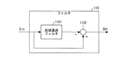
- FIG. 7 shows another configuration example of the filter 110. As shown in the figure, the filter 110 may be composed of a low-pass filter 1101 and a subtraction unit 1102.
- the rounding processing unit 132 generates a low-level removal signal SH2 by removing a low-level signal that can be regarded as noise included in the high-frequency signal SH1, so that the subsequent nonlinear processing unit 102 does not amplify the noise.
- the low level removal signal SH2 is generated by changing the signal value of the high frequency signal SH1 whose absolute value is equal to or lower than a predetermined lower limit LV to “0”.
- the input signal Sin can take any integer value from ⁇ 255 to 255, if the lower limit LV is “2”, the absolute value of the signal value of the high frequency signal SH1 is “2” or less. Are all regarded as noise and changed to “0” (that is, rounded).
- the limiter 133 removes the high level signal value included in the low level removal signal SH2 so as not to further amplify the signal having sufficient energy in the subsequent non-linear processing unit 102, thereby obtaining a high frequency signal. S11 is generated.
- the absolute value of the portion of the signal of the low level removal signal SH2 whose absolute value is larger than the upper limit value UV1 is set so that the signal value of the low level removal signal SH2 is equal to or less than the predetermined upper limit value UV1.
- a high frequency signal S11 is generated by performing a process of changing to the upper limit value UV1 or less (hereinafter also referred to as a clip process).
- the signal value of the part is changed to “64” or “ ⁇ 64” according to the sign. Alternatively, it may be changed to “0”.
- the filter 110 described above applies a signal that is limited to 3 rd MSB (about 64 or ⁇ 64 for an 8-bit signal) to, for example, 12-bit operation. Add to the input signal Sin. For this reason, the rounding processing unit 132 and the limiter 133 perform processing for limiting the calculation result performed by the filter 110 to the equivalent of an 8-bit signal.
- the high-frequency component extraction unit 11 includes the rounding processing unit 132 and the limiter 133.
- the high-frequency component extraction unit 11 may include a member that integrates them.
- the nonlinear processing unit 102a includes a non-linear calculation unit (even power calculation unit, square root calculation unit) 21, a code conversion unit (code conversion unit) 41, and a limiter (amplitude adjustment unit) 51. Yes.
- the non-linear operation unit 21 performs non-linear operation on the high-frequency signal S11 to generate a non-linear signal S21.
- the nonlinear calculation performed by the nonlinear calculation unit 21 will be described.
- the input signal value to the non-linear operation unit 21 is x
- the output signal value from the non-linear operation unit 21 is y
- the function f (x) is a non-linear function that monotonously increases positively and negatively (originally symmetric).
- the monotonic increase means a monotonic increase in a broad sense.
- the function f (x) is preferably
- at least in the vicinity of x “0”.
- Examples of such a function f (x) include those represented by the following mathematical formulas (1) to (3).
- the function f (x) represented by the following mathematical formulas (2) and (3) is used, the function f (x) has a large increase in the value of 0 ⁇ x ⁇ 1, so It is preferable to use it.
- the nonlinear signal S21 obtained by squaring the high-frequency signal S11 is the data string X1 2 , X2 2 , X3 2 ,.
- the resulting digital signal is the data string X1 2 , X2 2 , X3 2 ,.
- x may be normalized by 255 when using the function f (x).
- the right side x of the function f (x) represented by the above formula (2) is normalized by x / 255, and the right side is multiplied by 255. ) May be used.
- the following numerical formula (4) satisfies the condition of f (x)> x.
- x on the right side of the function f (x) represented by the equation (2) is normalized by 255 and the right side is multiplied by 255, but the value to be multiplied by the right side is normalized. It is not necessary to be the same value as the value (255 in this example), as long as the condition
- function f (x) may be a function using a trigonometric function shown in the following mathematical formula (6).
- the code conversion unit 41 Based on the sign bit information of the high-frequency signal S11, the code conversion unit 41 generates a code-converted signal S41 that reflects the sign of the high-frequency signal S11 in the nonlinear signal S21. That is, the code conversion unit 41 maintains the code as it is for the portion of the nonlinear signal S21 that has the same code as the high-frequency signal S11. On the other hand, the sign of the non-linear signal S21 with the sign different from the high frequency signal S11 is inverted.
- the limiter 51 performs a process (hereinafter also referred to as an amplitude adjustment process) for adjusting the amplitude (signal level and intensity) of the code conversion signal S41 generated by the code conversion unit 41, whereby the nonlinear processing signal S12 ( Horizontal-side nonlinear processing signal, vertical-side nonlinear processing signal, and time-side nonlinear processing signal).
- the limiter 51 multiplies the code conversion signal S41 by a predetermined magnification value ⁇ (
- magnification value ⁇ can be appropriately set according to the motion of the image and the amount of noise.
- magnification value ⁇ is set to a fixed value, for example, it is desirable that the absolute value is 0.5 or less.
- the limiter 51 does not further amplify a signal having sufficient energy, so that the absolute value of the signal of the nonlinear processing signal S12 is set so that the signal value of the nonlinear processing signal S12 is not more than a predetermined upper limit value UV2.
- a process of changing the absolute value to the upper limit value UV2 or less (hereinafter also referred to as clip processing) is performed.
- clip processing For a portion where the absolute value of the signal value of the nonlinear processing signal S12 exceeds “64”, the signal value of the portion is changed to “64” or “ ⁇ 64” according to the sign. Alternatively, it may be changed to “0”.
- the non-linear processing unit 102a may be configured not to include the limiter 51 and to perform neither the amplitude adjustment process nor the clip process of the code conversion signal S41.
- the code conversion signal S41 generated by the code conversion unit 41 is output from the nonlinear processing unit 102a as the nonlinear processing signal S12.
- the adder 15 generates the output signal Sout by adding the nonlinear processing signal S12 as a compensation signal to the input signal Sin. It is assumed that the adder 15 appropriately includes a delay element for adjusting the timing between the input signal Sin and the nonlinear processing signal S12.
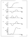
- FIGS. 8A to 8E are diagrams schematically illustrating waveforms of signals generated in the respective units of the sharpening processing unit 100a.
- the signal illustrated in FIG. 8A is input to the sharpening processing unit 100a as the input signal Sin.
- the high-frequency component extraction unit 11 when the input signal Sin is input to the high-frequency component extraction unit 11, the high-frequency component included in the input signal Sin is extracted, and the high-frequency signal S11 shown in FIG. 8B is generated.
- the signal shown in (a) of FIG. 9 is the same as the input signal Sin shown in (a) of FIG.
- the input signal Sin shown in (a) of FIG. 9 is enhanced, in the sharpening process using linear calculation, a high frequency signal is extracted from the input signal Sin shown in (a) of FIG. A method of adding the input signal Sin to the high frequency signal is used. Therefore, in the sharpening process using the linear operation, a signal component exceeding the Nyquist frequency that is not included in the input signal Sin is not added.
- a signal shown in FIG. 9B is generated.
- the rise in the signal shown in FIG. 9B is steeper than the rise of the signal in the input signal Sin shown in FIG. 9A, but the nonlinear processing signal S12 generated by the sharpening processing unit 100a.
- the rising edge of the signal in (e) of FIG. 8 becomes steeper.
- the nonlinear processing unit 102a described above may be configured to differentiate the nonlinear signal S21 generated by the nonlinear computing unit 21. This is because the direct current component included in the nonlinear signal S21 can be removed by differentiating the nonlinear signal S21.
- FIG. 10 is a block diagram illustrating a configuration of the sharpening processing unit 100b.
- the sharpening processing unit 100b includes a high-frequency component extraction unit 11, a nonlinear processing unit 102b, and an addition unit 15.
- the non-linear processing unit 102b includes a differentiating unit (differentiating means) 31 between the non-linear calculating unit 21 and the code converting unit 41 in addition to the configuration of the non-linear processing unit 102a shown in FIG. Since the high-frequency component extraction unit 11, the members other than the differentiation unit 31 of the nonlinear processing unit 102b, and the addition unit 15 are the same as those described above, detailed description thereof is omitted here.
- the differentiating unit 31 generates the differential signal S31 by differentiating the non-linear signal S21 generated by the non-linear operation unit 21.
- FIG. 11 is a block diagram illustrating a configuration of the differentiating unit 31.
- the differentiating unit 31 includes a unit delay element 3111 and a subtracting unit 3112, and calculates a backward difference with respect to a signal input to the differentiating unit 31.
- the code converting unit 41 converts a signal obtained by reflecting the sign of the high frequency signal S11 to the nonlinear signal S21 based on the sign bit information of the high frequency signal S11. It generates as S42. That is, the code conversion unit 41 maintains the code as it is for the portion of the differential signal S31 that has the same code as the high-frequency signal S11. On the other hand, the sign of the non-linear signal S21 with the sign different from the high frequency signal S11 is inverted.
- the limiter 51 generates a nonlinear processing signal S12 by performing amplitude adjustment processing and clipping processing on the code conversion signal S42 generated by the code conversion unit 41.
- the amplitude of the code conversion signal S42 is adjusted by multiplying the code conversion signal S42 by a predetermined magnification value ⁇ .
- the non-linear processing unit 102b may be configured not to include the limiter 51 and to perform neither the amplitude adjustment process nor the clip process of the code conversion signal S42.
- the code conversion signal S42 generated by the code conversion unit 41 is output from the nonlinear processing unit 102b as the nonlinear processing signal S12.
- FIG. 12 are diagrams schematically showing waveforms of signals generated in the respective units of the sharpening processing unit 100b.
- the signal shown in FIG. 12A is input to the sharpening processing unit 100b as the input signal Sin.
- the signal shown to (a) of FIG. 12 is the same as the signal shown to (a) of FIG.
- the high-frequency component extraction unit 11 when the input signal Sin is input to the high-frequency component extraction unit 11, the high-frequency component included in the input signal Sin is extracted, and the high-frequency signal S11 shown in FIG. 12B is generated.
- a differentiation signal S31 shown in (d) of FIG. 12 is generated.
- the differential signal S31 the direct current component included in the nonlinear signal S21 is removed.
- FIG. 13 is a block diagram illustrating a configuration of the sharpening processing unit 100c.
- the sharpening processing unit 100c includes a high-frequency component extraction unit 11, a nonlinear processing unit 102c, and an addition unit 15.
- the nonlinear processing unit 102 c includes a nonlinear computing unit (odd power computing unit) 22 and a limiter 51. Since the high-frequency component extraction unit 11, the limiter 51, and the addition unit 15 are the same as those described above, detailed description thereof is omitted here.
- the non-linear operation unit 22 performs non-linear operation on the high-frequency signal S11 to generate a non-linear signal S22.
- the nonlinear calculation performed by the nonlinear calculation unit 22 will be described.
- the input signal value to the non-linear operation unit 22 is x
- the output signal value from the non-linear operation unit 22 is y
- the function g (x) is a non-linear function that monotonously increases positively and negatively (originally symmetric).
- the monotonic increase means a monotonic increase in a broad sense.
- the function g (x) is preferably
- at least in the vicinity of x “0”.
- the data string constituting the high-frequency signal S11 is X1, X2, X3,...
- the nonlinear signal S22 obtained by squaring the high-frequency signal S11 is represented by the data string X1 3 , X2 3 , X3 3 ,.
- the resulting digital signal is represented by the data string X1 3 , X2 3 , X3 3 ,.
- the limiter 51 generates the nonlinear processing signal S12 by performing amplitude adjustment processing and clipping processing on the nonlinear signal S22 generated by the nonlinear calculation unit 22.
- the non-linear processing unit 102c may be configured not to include the limiter 51 and to perform neither the amplitude adjustment process nor the clip process of the non-linear signal S22.
- the nonlinear signal S22 generated by the nonlinear computing unit 22 is output from the nonlinear processing unit 102c as the nonlinear processing signal S12.
- FIG. 14 are diagrams schematically showing waveforms of signals generated in the respective units of the sharpening processing unit 100c.
- the signal shown in FIG. 14A is input to the sharpening processing unit 100c as the input signal Sin.
- the signal shown in (a) of FIG. 14 is the same as the signal shown in (a) of FIG.
- the high-frequency component extraction unit 11 when the input signal Sin is input to the high-frequency component extraction unit 11, the high-frequency component included in the input signal Sin is extracted, and the high-frequency signal S11 shown in FIG. 14B is generated.
- the input signal Sin is expressed by a function F (x) where time is x.
- the function F (x) can be expressed by a Fourier series as shown in the following formula (8).
- N is the order of the highest frequency harmonic that does not exceed the Nyquist frequency fs / 2 with respect to the sampling frequency fs. That is, the following formula (9) is satisfied.
- G (x) is expressed by the following formula (10).
- the input signal Sin input to the sharpening processing unit 100A includes the signal G (x) or the high-frequency component of the signal G (x).
- (G (x)) 2 includes angular frequency components such as (N + 1) ⁇ , (N + 2) ⁇ ,.
- (G (x)) 2 includes a frequency component higher than the Nyquist frequency fs / 2. That is, the nonlinear signal S21 generated by the nonlinear computing unit 21 includes a frequency component higher than the Nyquist frequency fs / 2, such as a harmonic component such as a frequency 2N ⁇ / (2 ⁇ ).
- Equations (23) and (24) can be rewritten.
- (G (x)) 3 includes a frequency component 3N times the basic angular frequency ⁇ and a frequency component -3N times.
- (G (x)) 3 includes various frequency components from ⁇ 3N to 3N times the basic angular frequency ⁇ . I understand that.
- (G (x)) 3 includes a frequency component higher than the Nyquist frequency fs / 2. That is, the nonlinear signal S22 generated by the nonlinear operation unit 22 includes a frequency component higher than the Nyquist frequency fs / 2, such as a harmonic component having a frequency of 3N ⁇ / (2 ⁇ ).
- the output signal Sout generated by the sharpening processing unit 100A includes a high frequency component not included in the input signal Sin, that is, a frequency component higher than the Nyquist frequency.
- FIG. 15 is a block diagram showing a configuration of the sharpening processing unit 100d.
- the sharpening processing unit 100d includes a high frequency component extraction unit 11, a nonlinear processing unit 102d, and an addition unit 15. Since the high-frequency component extraction unit 11 and the addition unit 15 are the same as those described above, detailed description thereof is omitted here.
- the nonlinear processing unit 102d includes a square calculation unit 61, a first differentiation unit 71, a second differentiation unit 81, and a multiplication unit 91.
- the square calculator 61 generates a square signal S61 by squaring the high-frequency signal S11. That is, if the data sequence that constitutes the high-frequency signal S11 is X1, X2, X3,..., The square signal S61 obtained by squaring the high-frequency signal S11 is represented by the data sequences X1 2 , X2 2 , X3 2 ,. The resulting digital signal.
- the first differentiating unit 71 generates the first differential signal S71 by differentiating the square signal S61 generated by the square calculating unit 61.
- the structure of the 1st differentiation part 71 is the structure similar to the differentiation part 31, for example.
- the second differentiator 81 generates the second differential signal S81 by differentiating the input signal Sin.
- the structure of the 2nd differentiation part 81 is the structure similar to the differentiation part 31, for example.
- the multiplication part 91 produces
- the processing signal S12 is a digital signal composed of data strings U1, V1, U2, V2, U3, V3,.
- the square calculation unit 61 is provided in order to perform nonlinear calculation.
- a fourth power calculation unit that squares the high-frequency signal S11 may be used instead of the square calculation unit 61. More generally, a power calculation unit that generates a signal corresponding to the power of the high-frequency signal S11 having an even number of 2 or more as a power index may be used.
- the configuration includes the square calculation unit 61.
- a configuration including an absolute value processing unit 62 that calculates the absolute value of the input signal is good.
- FIG. 16 is a block diagram illustrating a configuration of the sharpening processing unit 100e.
- the sharpening processing unit 100e includes a high-frequency component extraction unit 11, a nonlinear processing unit 102e, and an addition unit 15. Since the high-frequency component extraction unit 11 and the addition unit 15 are the same as those described above, detailed description thereof is omitted here.
- the nonlinear processing unit 102e includes an absolute value processing unit 62, a first differentiation unit 71, a second differentiation unit 81, and a multiplication unit 91. Since the first differentiating unit 71, the second differentiating unit 81, and the multiplying unit 91 are the same as those described above, detailed description thereof is omitted here.
- the absolute value processing unit 62 generates an absolute value signal S62 that is a signal corresponding to the absolute value of the high-frequency signal S11. That is, if the data string that constitutes the high-frequency signal S11 is X1, X2, X3,...,
- the absolute value signal S62 is a digital signal composed of the data strings
- the first differentiating unit 71 generates the first differential signal S72 by differentiating the absolute value signal S62 generated by the absolute value processing unit 62.
- the high frequency component included in the input signal SR is usually not constant, it is preferable to set the degree of sharpening performed by the sharpening processing unit 100A according to the amount of the high frequency component included in the input signal SR. . That is, when there are few high frequency components contained in the input signal SR, it is preferable to increase the degree of sharpening performed by the sharpening processing unit 100A. On the other hand, when there are many high frequency components contained in the input signal SR, it is preferable to reduce the degree of sharpening performed by the sharpening processing unit 100A. By setting in this way, the sharpening can be appropriately performed without being too strong or too weak.
- the signal processing device 500 according to the present embodiment is referred to as a signal processing device 500b.
- members having the same functions as those shown in the first embodiment are denoted by the same reference numerals, and the description thereof is omitted unless specifically described.
- FIG. 17 is a block diagram illustrating a configuration of the signal processing device 500b.
- the sharpening processing unit 100 further includes a sharpness adjustment instruction section (amplitude magnification value setting means, filter coefficient setting means) 400.
- the high region removal filter 350 may be provided.
- the sharpness adjustment instruction unit 400 receives either the input signal SA or the oversampling signal S200 as input, and extracts a high frequency component contained in the input signal. Note that FIG. 17 illustrates the case where the input signal SA is input.
- the sharpness adjustment instruction unit 400 includes a high-pass filter therein in order to extract a high-frequency component contained in the input signal.
- the high-pass filter is a generally known high-pass filter, and may be any filter as long as it removes the DC component of the input signal. Further, it may be a one-dimensional filter or a two-dimensional filter.
- the sharpness adjustment instruction unit 400 sets the degree of sharpening to the sharpening processing unit 100A by one of the following two setting methods according to the amount of the extracted high-frequency component.
- the first setting method is a method of setting a magnification value ⁇ by which the code conversion signal S41 is multiplied by the limiter 51 of the sharpening processing unit 100A. That is, the smaller the amount of high-frequency components extracted by the sharpness adjustment instruction unit 400, the larger the magnification value ⁇ is set.
- the magnification value ⁇ By setting the magnification value ⁇ to a large value, the amplitude of the code conversion signal S41 increases, and as a result, the amplitude of the nonlinear processing signal S12 increases. This increases the degree of sharpening performed by the sharpening processing unit 100A.
- the magnification value ⁇ By setting the value of the magnification value ⁇ to be small, the amplitude of the code conversion signal S41 becomes small, and as a result, the amplitude of the nonlinear processing signal S12 becomes small. This reduces the degree of sharpening performed by the sharpening processing unit 100A.
- the second setting method is a method of setting the coefficient Cp of the filter 110 included in the high-frequency component extraction unit 11 of the sharpening processing unit 100A (changing the frequency characteristic). That is, each of the coefficients Cp is set such that the smaller the amount of high-frequency components extracted by the sharpness adjustment instruction unit 400 is, the more frequency components are allowed to pass through the filter 110.
- the coefficient Cp is set in this way, the high frequency signal SH1 becomes large, and as a result, the amplitude of the nonlinear processing signal S12 becomes large. This increases the degree of sharpening performed by the sharpening processing unit 100A.
- each of the coefficients Cp is set so that the higher the amount of the high-frequency component extracted by the sharpness adjustment instruction unit 400, the smaller the frequency component that is passed by the filter 110.
- the coefficient Cp is set in this way, the high frequency signal SH1 becomes small, and as a result, the amplitude of the nonlinear processing signal S12 becomes small. This reduces the degree of sharpening performed by the sharpening processing unit 100A.
- a sharpening processing unit is set by setting a magnification value ⁇ by which the limiter 51 multiplies the code conversion signal S41 or by setting a coefficient Cp of the filter 110.
- the degree of sharpening applied at 100A was set.
- one sharpening processor 100A is selected from among a plurality of sharpening processors 100A in which at least one of the magnification value ⁇ and the coefficient Cp is different, and the sharpening is performed.
- the signal processing device 500 is referred to as a signal processing device 500c.
- members having the same functions as those of the members shown in the first and second embodiments are given the same reference numerals, and explanations thereof are omitted unless otherwise specified.
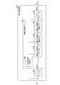
- FIG. 18 is a block diagram illustrating a configuration of the signal processing device 500c.
- the signal processing device 500c is replaced with a signal switching unit 600, a sharpness adjustment instruction unit 410, and w (w is an arbitrary number of 2 or more) instead of the sharpening processing unit 100 included in the signal processing device 500a.
- the high region removal filter 350 may be provided.
- the sharpening processing unit 100A_1 to the sharpening processing unit 100A_w are set to have different sharpening levels.
- the sharpening degree is set by adjusting at least one of the magnification value ⁇ multiplied by the code conversion signal S41 by the limiter 51 and the coefficient Cp of the filter 110.
- the signal switching unit 600 is a switch that connects the connection point In to any one of the connection points Out_1 to Out_w according to the signal output from the sharpness adjustment instruction unit 410.
- the sharpness adjustment instruction unit 410 receives either the input signal SA or the oversampling signal S200 and extracts a high-frequency component contained in the input signal. To do. FIG. 18 illustrates the case where the input signal SA is input.
- the sharpness adjustment instruction unit 410 includes a high-pass filter therein in order to extract a high-frequency component contained in the input signal. Then, the sharpness adjustment instruction unit 410 outputs a signal indicating which of the connection point Out_1 to the connection point Out_w is connected to the signal switching unit 600 according to the amount of the extracted high frequency component.
- the sharpening processing unit 100A_1 is set to have a higher sharpening degree than the sharpening processing unit 100A_2.
- a predetermined threshold hereinafter referred to as threshold Tw
- Tw a predetermined threshold
- Embodiment 4 When the sharpening process is performed on the image represented by the input signal SA, the sharpening process can be performed in the horizontal direction and the vertical direction so that the image can be highly sharpened. In addition, when the image represented by the input signal SA is a moving image, it can be sharpened to a higher degree by further performing a sharpening process in the time direction. Note that, after sharpening in the time direction, it is possible to suppress the occurrence of afterimages.
- the signal processing device 500 is referred to as a signal processing device 500d.
- members having the same functions as those shown in the first to third embodiments are given the same reference numerals, and explanations thereof are omitted unless otherwise specified.
- each of the unit delay elements 111h included in the high-frequency component extraction unit 11 included in the sharpening processing unit 100A is (1) a signal delayed by unit time in the horizontal direction of the image represented by the input signal. May be output, or (2) a signal delayed by unit time in the vertical direction of the image represented by the input signal may be output. Further, (3) a signal delayed by unit time (for each frame) in the time direction of the moving image represented by the input signal may be output.
- the sharpening processing unit 100A performs a sharpening process in the horizontal direction of the image.
- the sharpening process in the horizontal direction is described as horizontal process.
- the sharpening processing unit 100A performs the sharpening processing in the vertical direction of the image.
- the sharpening process in the vertical direction is referred to as vertical process.
- the sharpening processing unit 100A performs a sharpening process in the time direction of the moving image.
- the sharpening process in the time direction will be referred to as the time direction process.
- FIG. 19A and FIG. 19B are block diagrams showing the configuration of the signal processing device 500d.
- a signal processing device 500d includes an oversampler 200, a sharpening processing unit 100A that performs horizontal processing, and a sharpening processing unit 100A that performs vertical processing. 100.
- the sharpening processing unit 100 further includes a sharpening processing unit 100A that performs time direction processing. May be.
- the connection order of the sharpening processing unit 100A that performs horizontal processing, the sharpening processing unit 100A that performs vertical processing, and the sharpening processing unit 100A that performs time processing is not particularly limited. It may be.
- the signal output from the sharpening processor 100A that performs horizontal processing corresponds to the “horizontal sharpening signal” recited in the claims, and is output from the sharpening processor 100A that performs vertical processing.
- the signal corresponds to the “vertical sharpening signal” recited in the claims, and the signal output from the sharpening processing unit 100A that performs time direction processing is the “time sharpening signal” recited in the claims. It corresponds to.
- the signal processing device 500d may include a downsampler 300. Whether or not the down sampler 300 is provided depends on the angle of view of the image represented by the output signal SO as described above. Further, in the drawing, a configuration without the high-frequency removal filter 350 is illustrated, but the high-frequency removal filter 350 may be provided.
- the horizontal direction processing, the vertical direction processing, and the time direction processing can be performed on the image represented by the input signal SA.
- the image can be highly sharpened.
- a part of the sharpening processing unit 100A may be omitted in order to reduce cost and improve processing speed.
- the sharpening processing unit 100A that performs time direction processing is omitted, and the sharpening processing unit 100A that performs horizontal processing and vertical processing are performed. It is good also as a structure provided only with the sharpening process part 100A to perform.
- the degree of sharpening performed by the sharpening processing unit 100A may be further set according to the amount of high frequency components included in the input signal SR. preferable.
- the signal processing device 500 is referred to as a signal processing device 500e.
- members having the same functions as those shown in the first to fourth embodiments are given the same reference numerals, and explanations thereof are omitted unless otherwise specified.
- FIG. 20 is a block diagram illustrating a configuration of the signal processing device 500e.
- the signal processing device 500e has a configuration in which a sharpness adjustment instruction unit 420 is added to the sharpening processing unit 100 of the signal processing device 500d.
- FIG. 20 although the structure provided with the sharpening process part 100A which performs a time direction process is illustrated, it does not necessarily need to be provided. Further, in the drawing, a configuration without the high-frequency removal filter 350 is illustrated, but the high-frequency removal filter 350 may be provided.
- the sharpness adjustment instruction unit 420 receives either the input signal SA or the oversampling signal S200 as input, and extracts a high-frequency component included in the input signal.
- FIG. 20 illustrates the case where the input signal SA is input.
- the sharpness adjustment instruction unit 420 includes a high-pass filter therein in order to extract a high-frequency component contained in the input signal.
- the high-pass filter is a generally known high-pass filter, and may be any filter as long as it removes the DC component of the input signal. Further, it may be a one-dimensional filter or a two-dimensional filter.
- the sharpness adjustment instruction unit 420 then performs a sharpening processing unit 100A that performs horizontal processing, a sharpening processing unit 100A that performs vertical processing, and a sharpening that performs time-direction processing according to the amount of the extracted high-frequency component.
- the degree of sharpening is set for at least one of the processing units 100A. Since the setting method of the sharpening degree is the same as the setting method described in the second embodiment, the description thereof is omitted here.
- Embodiment 6 instead of the configuration described in the fifth embodiment, as in the configuration described in the third embodiment, one sharpening process is performed from among a plurality of sharpening processing units 100A in which at least one of the magnification value ⁇ and the coefficient Cp is different. It is good also as a structure which selects the part 100A.
- one sharpening processing unit 100A that performs horizontal processing and one sharpening processing unit 100A that performs vertical processing according to the amount of high-frequency components included in the input signal SR, A mode of selecting one sharpening processing unit 100A that performs time direction processing will be described.
- This embodiment will be described below with reference to FIG.
- the signal processing device 500 according to the present embodiment is referred to as a signal processing device 500f.
- members having the same functions as those shown in the first to fifth embodiments are given the same reference numerals, and explanations thereof are omitted unless otherwise specified.
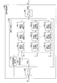
- FIG. 21 is a block diagram illustrating a configuration of the signal processing device 500f.
- the signal processing device 500f is replaced with a sharpening processing unit 100 provided in the signal processing device 500d, a sharpness adjustment instruction unit 410, a signal switching unit 600, and w (w is an arbitrary number of 2 or more).
- Sharpening processing units 100A Sharppening processing unit 100A_11 to sharpening processing unit 100A_1w
- sharpening processing units 100A sharpening processing units 100A_21 to 100
- a sharpening processing unit 100 including a sharpening processing unit 100A_2w) and a sharpening processing unit 100A (sharpening processing unit 100A_31 to sharpening processing unit 100A_3w) that performs w time direction processing. Further, in the drawing, a configuration without the high-frequency removal filter 350 is illustrated, but the high-frequency removal filter 350 may be provided.
- the sharpening processing unit 100A_11 to the sharpening processing unit 100A_1w are set to have different sharpening levels.
- the sharpening processing unit 100A_21 to the sharpening processing unit 100A_2w are set to have different sharpening levels.
- the sharpening processing unit 100A_31 to the sharpening processing unit 100A_3w are set to have different sharpening levels.
- the sharpening degree is set by adjusting at least one of the magnification value ⁇ multiplied by the code conversion signal S41 by the limiter 51 and the coefficient Cp of the filter 110.
- the sharpening processing unit 100A_11 has a higher sharpening degree than the sharpening processing unit 100A_12
- the sharpening processing unit 100A_21 has a higher sharpening degree than the sharpening processing unit 100A_22, and the sharpening process.
- the part 100A_31 is set to have a higher degree of sharpening than the sharpening processing part 100A_32.
- the sharpness adjustment instruction unit 400 switches a signal indicating that the connection point In_1 is connected to the connection point Out_11. To the unit 600. This increases the degree of sharpening of the original image.
- the sharpness adjustment instruction unit 400 when the amount of the extracted high-frequency component is equal to or greater than the threshold value Tw, the sharpness adjustment instruction unit 400 outputs a signal indicating that the connection point In_1 is connected to the connection point Out_12 to the signal switching unit 600. This reduces the degree of sharpening of the original image.
- FIG. 22A shows an example of an original image represented by an input signal SR. It should be noted that the image shown in the figure is a size smaller than the actual size due to space limitations. As shown in the figure, the image is in a state of feeling a slight blur.
- FIG. 22B is a diagram showing an example of an image represented by an oversampling signal S200 obtained via the oversampler 200 from the input signal SR representing the image shown in FIG. is there.
- the vertical and horizontal dimensions are each doubled.
- (c) of FIG. 22 shows an example of an image represented by a sharpening signal S100 obtained through the sharpening processing unit 100 from the oversampling signal S200 representing the image shown in (b) of FIG. FIG.
- a sharpening signal S100 obtained through the sharpening processing unit 100 from the oversampling signal S200 representing the image shown in (b) of FIG. FIG.
- blurs such as the brightness of human eyes, nose lines, and scarf patterns are greatly reduced compared to the image shown in (b) of FIG. 22, and the image quality and the sense of resolution are improved. It can be seen that it has improved.
- FIG. 22D shows an example of an image represented by the downsampling signal S300 obtained via the downsampler 300 from the sharpening signal S100 representing the image shown in FIG. It is. Also in the image shown in FIG. 22 (d), compared to the image shown in FIG. 22 (a), the blurring feeling such as the brightness of the eyes of the person, the nose and the scarf pattern is greatly reduced, and the image quality and resolution are reduced. It can be seen that the feeling is improved.
- At least one of the nonlinear processing means, the horizontal nonlinear processing means, the vertical nonlinear processing means, and the time nonlinear processing means has a value of an input signal as a value. In the vicinity of 0, a configuration in which a signal whose absolute value is larger than the absolute value of the input signal may be output.
- the value of the signal added to the signal to be sharpened when generating the output signal is set to a value larger than the signal to be sharpened. be able to.
- At least one of the low frequency component removing means, the horizontal low frequency component removing means, the vertical low frequency component removing means, and the time side low frequency component removing means is A low-level signal removing unit that changes a signal value of a portion whose absolute value is smaller than a predetermined lower limit value to 0 among signals to be output, and a signal of a portion whose absolute value is larger than a predetermined upper limit value among output signals
- the configuration may further include a high-level signal removing unit that changes the value of the absolute value only to the upper limit value or less while maintaining the sign.
- the signal value of the part whose absolute value is smaller than a predetermined lower limit value to 0 among the signals to output the signal value of the part whose absolute value is larger than the predetermined upper limit value among output signals Only the absolute value is changed below the upper limit value while maintaining the sign.
- noise included in the output signal can be removed, and high-frequency components with large energy included in the output signal can be prevented from being amplified by nonlinear processing.
- each block of the signal processing device 500 may be configured as hardware by a logic circuit formed on an integrated circuit (IC chip), or software using a CPU (central processing unit) as follows. It may be realized by.
- IC chip integrated circuit
- CPU central processing unit
- the signal processing device 500 When implemented by software, the signal processing device 500 (particularly the sharpening processing unit 100) includes a CPU that executes instructions of a control program that implements each function, a ROM (read only memory) that stores the program, and the program And a storage device (recording medium) such as a memory for storing the program and various data.
- An object of the present invention is a recording medium on which a program code (execution format program, intermediate code program, source program) of a control program of the signal processing device 500, which is software that realizes the functions described above, is recorded so as to be readable by a computer. This can also be achieved by supplying the signal processing device 500 and reading and executing the program code recorded on the recording medium by the computer (or CPU or MPU).
- Examples of the recording medium include tapes such as magnetic tapes and cassette tapes, magnetic disks such as floppy (registered trademark) disks / hard disks, and disks including optical disks such as CD-ROM / MO / MD / DVD / CD-R.
- IC cards including memory cards
- semiconductor memories such as mask ROM / EPROM / EEPROM / flash ROM
- logic circuits such as PLD (Programmable logic device), etc. it can.
- the signal processing device 500 may be configured to be connectable to a communication network, and the program code may be supplied via the communication network.
- the communication network is not particularly limited.
- the Internet intranet, extranet, LAN, ISDN, VAN, CATV communication network, virtual private network, telephone line network, mobile communication network, satellite communication. A net or the like is available.
- the transmission medium constituting the communication network is not particularly limited.
- infrared rays such as IrDA and remote control
- Bluetooth It can also be used for wireless such as registered trademark), IEEE 802.11 wireless, HDR (High Data Rate), NFC (Near Field Communication), DLNA (Digital Living Network Alliance), mobile phone network, satellite line, terrestrial digital network, etc. .
- means does not necessarily mean physical means, but includes cases where the functions of each means are realized by software. Further, the function of one means may be realized by two or more physical means, or the functions of two or more means may be realized by one physical means.
- the signal processing device is a signal processing device that performs the process of sharpening the image on the input signal representing the image and outputs the output signal representing the sharpened image.
- a signal interpolating means for generating a post-interpolation signal by interpolating the signal to increase the sampling frequency with respect to the input signal, and a high frequency component in the post-interpolation signal using the post-interpolation signal as input.
- Sharpening means for generating a sharpening signal obtained by monotonically increasing non-linearly in a broad sense, and outputting the sharpening signal as the output signal.
- An integrated circuit is an integrated circuit that performs processing for sharpening the image on an input signal representing an image and outputs an output signal representing the sharpened image, the input signal representing the image
- a signal interpolation circuit that generates an interpolated signal by interpolating the signal to increase the sampling frequency and the post-interpolation signal as inputs, and the high-frequency components in the post-interpolation signal are non-linearly broadly defined.
- a sharpening circuit that generates a sharpened signal that is monotonously increased, and outputs the sharpened signal as the output signal.
- the signal processing apparatus may be configured to further include a signal thinning means for thinning out the signal from the sharpening signal in order to lower the sampling frequency.
- the signal is further thinned out from the sharpened signal in order to lower the sampling frequency. That is, downsampling is performed on the sharpening signal. Then, the signal after interpolation after down-sampling is output as an output signal.
- the output signal can be output.
- the input signal is a signal for standard definition television (SDTV: Standard Definition Television) (horizontal pixel number: 720), and the output signal is a high definition television (HDTV) (horizontal pixel number: 1920).
- SDTV Standard Definition Television
- HDTV high definition television
- the input signal is oversampled to a signal having a horizontal pixel number of 5670, which is the least common multiple of 720 and 1920, and then the signal is sharpened, downsampled, and output as an output signal. do it.
- oversampling and downsampling may be performed in the time direction.
- a system of 60 fields (30 frames) / second is used in Japan and the United States, and a system of 50 fields (25 frames) / second is used in Europe. Therefore, when switching between an input signal and an output signal between them, the input signal is oversampled to a signal of 300 fields / second, which is the least common multiple of 60 and 50, and then sharpening processing is performed on the signal. And downsampling to produce an output signal.
- the signal processing apparatus further includes a high frequency removing unit that removes a high-frequency component included in the sharpening signal before thinning the signal from the sharpening signal by the signal thinning unit. It may be.
- the high frequency components included in the sharpening signal are further removed before thinning out the signal from the sharpening signal.
- the sharpening unit further generates a low frequency removal signal by removing a low frequency component including at least a DC component from the frequency component contained in the post-interpolation signal.
- a low frequency removal signal by removing a low frequency component including at least a DC component from the frequency component contained in the post-interpolation signal.
- the low frequency removal signal is generated by removing at least the direct current component from the frequency component included in the post-interpolation signal. Then, when the sign of the low frequency removal signal is maintained, and at least when the value of the low frequency removal signal is in the vicinity of 0, a nonlinear processing signal that monotonously increases in a non-linear and broad sense with respect to the low frequency removal signal Is generated. Then, the non-linear processing signal is added to the low frequency removal signal to generate an addition signal and output it as the sharpening signal.
- a signal obtained by subjecting the high-frequency component included in the post-interpolation signal to nonlinear processing can be output as a sharpening signal.
- the sharpening signal is generated, for example, by adding the low-frequency removal signal and a non-linear processing signal subjected to non-linear processing such as squaring the low-frequency removal signal.
- the sign of the sharpening signal maintains the sign of the low frequency removal signal.
- the sharpening signal generated in this way includes high frequency components that are not included in the original frequency components.
- the generated sharpening signal includes a frequency component higher than the Nyquist frequency, which is a half of the sampling frequency when the interpolated signal is discretized.
- the Nyquist frequency is a half of the sampling frequency when the interpolated signal is discretized.
- the signal processing apparatus has a sharpening signal in which the rising and falling edges of the signal corresponding to the edge portion included in the input signal are steeper than in the process of performing a linear operation on the interpolated signal. Can be generated, and the image quality and the sense of resolution can be greatly improved.
- the sharpening unit further includes a pixel group including pixels arranged adjacent to each other in the horizontal direction of the image represented by the post-interpolation signal.
- a horizontal-side sharpening means for generating a horizontal sharpening signal obtained by sharpening a horizontal signal that is a signal to be expressed, and the horizontal sharpening signal as an input, and adjacent to the vertical direction of the image represented by the horizontal sharpening signal.
- Vertical sharpening means for generating a vertical sharpening signal obtained by sharpening a vertical direction signal, which is a signal representing a pixel group consisting of pixels arranged in parallel, and outputting the sharpening signal
- the horizontal sharpening means includes: A horizontal side low frequency component removing means for generating a horizontal side low frequency removal signal by removing a low frequency component including at least a direct current component from the frequency component contained in the horizontal direction signal; and the horizontal side low frequency removal Horizontal non-linear processing signal that monotonically increases in a non-linear and broad sense with respect to the horizontal low-frequency removal signal when the sign of the signal is maintained and at least the value of the horizontal low-frequency removal signal is near 0
- Horizontal side nonlinear processing means for generating, and horizontal side addition means for generating a horizontal addition signal by adding the horizontal nonlinear processing signal and the post-interpolation signal and outputting as a horizontal sharpening signal
- the vertical side sharpening means generates vertical side low frequency component removal means by removing a low
- At least a direct current component is included from the frequency component included in the horizontal direction signal that is a signal representing a pixel group composed of pixels lined up adjacent in the horizontal direction of the image represented by the post-interpolation signal.
- a horizontal low frequency removal signal is generated by removing the low frequency component, the sign of the horizontal low frequency removal signal is maintained, and at least the value of the horizontal low frequency removal signal is near zero.
- a horizontal non-linear processing signal that monotonously increases in a non-linear and broad sense with respect to the horizontal low-frequency removal signal, and a horizontal sharpening signal by adding the horizontal non-linear processing signal and the interpolated signal To do.
- a low frequency component including at least a direct current component is removed from a frequency component included in a vertical direction signal that is a signal representing a pixel group including pixels arranged adjacent to each other in the vertical direction of the image represented by the horizontal sharpening signal.
- the vertical low frequency rejection signal is generated, the sign of the vertical low frequency rejection signal is maintained, and at least when the value of the vertical low frequency rejection signal is near 0, the vertical low frequency signal is reduced.
- a vertical-side nonlinear processing signal that monotonously increases in a non-linear and broad sense with respect to the frequency removal signal is generated, and a vertical sharpening signal is obtained by adding the vertical-side nonlinear processing signal and the horizontal sharpening signal. Then, the vertical sharpening signal is output as a sharpening signal.
- a signal obtained by performing non-linear processing on the high-frequency component included in the horizontal direction and the vertical direction of the post-interpolation signal can be output as a sharpening signal.
- the horizontal sharpening signal is generated by adding the input signal and the horizontal nonlinear processing signal subjected to nonlinear processing such as squaring the horizontal low frequency removal signal.
- the sign of the generated signal maintains the sign of the horizontal low frequency removal signal.
- the vertical sharpening signal is generated by adding an input signal and a vertical nonlinear processing signal subjected to nonlinear processing such as squaring the vertical low frequency removal signal.
- the sign of the generated signal maintains the sign of the sign of the vertical low frequency removal signal.
- the horizontal sharpening signal and the vertical sharpening signal include high-band frequency components that are not included in the post-interpolation signal.
- the horizontal sharpening signal and the vertical sharpening signal include higher frequency components than the Nyquist frequency, which is a half of the sampling frequency when the interpolated signal is discretized.
- the signal processing apparatus has a sharpening signal in which the rising and falling edges of the signal corresponding to the edge portion included in the input signal are steeper than in the process of performing a linear operation on the interpolated signal.
- the image quality and the sense of resolution of the image represented by the input signal can be greatly improved.
- the sharpening means further includes a pixel composed of pixels arranged adjacent to each other in the time direction of the image represented by the vertical sharpening signal, with the vertical sharpening signal being input.
- a time sharpening unit that generates a time sharpening signal obtained by sharpening a time direction signal that is a signal representing a group, and the time sharpening unit includes at least a direct current component from frequency components included in the time direction signal.
- Time side low frequency component removal means for generating a time side low frequency removal signal by removing the low frequency component, and the sign of the time side low frequency removal signal is maintained, and at least the time side low frequency removal is performed.
- a time-side non-linear processing means for generating a time-side non-linear processing signal that monotonically increases in a non-linear and broad sense with respect to the time-side low frequency removal signal when the value of the signal is near 0; It may be configured to include a time side adding means for outputting the time sharpening signal by adding the shape processing signal and the vertical sharpening signals.
- the time sharpening signal is generated by sharpening the time direction signal that is a signal representing a pixel group composed of pixels arranged adjacent to each other in the time direction of the image represented by the vertical sharpening signal.
- the time sharpening means generates a time-side low-frequency removal signal by removing a low-frequency component including at least a direct current component from the frequency component contained in the time-direction signal, and generates the time-side low-frequency removal signal.
- time-side nonlinear processing signal that monotonically increases in a non-linear and broad sense with respect to the time-side low frequency rejection signal when the sign is maintained and at least the value of the time-side low frequency rejection signal is near 0 Then, the time sharpening signal is generated by adding the time-side nonlinear processing signal and the vertical sharpening signal.
- the signal processing apparatus has an effect that the image represented by the input signal can be further sharpened.
- At least one of the nonlinear processing means, the horizontal nonlinear processing means, the vertical nonlinear processing means, and the time nonlinear processing means calculates an even number of 2 or more as a power exponent.
- the even power calculation means for generating an even power signal by raising the input signal, and the sign of the part of the even power signal, the sign of which is different from that of the input signal.
- a code conversion means for inverting, and outputting the even power signal whose code is inverted by the code conversion means.
- an even power signal is generated by powering an input signal with an even number of 2 or more as a power index, and the sign of the even power signal has a positive or negative sign.
- the sign of the portion different from the frequency component before powering is inverted, and the inverted signal is output.
- the input signal is raised to the power of an even number equal to or greater than 2, and the sign is output with the sign of the low-frequency removal signal before the power raised while maintaining the sign.
- a signal obtained by adding the output signal and the input signal includes a high frequency component not included in the input signal.
- At least one of the nonlinear processing means, the horizontal nonlinear processing means, the vertical nonlinear processing means, and the time nonlinear processing means calculates an even number of 2 or more as a power exponent.
- an even power calculation means for generating an even power signal by raising an input signal a differentiation means for generating a differential signal by differentiating the even power signal, and among the differential signals
- the sign conversion means for inverting the sign of a part different from the input signal may be provided, and the differential signal with the sign inverted by the sign conversion means may be output.
- an even power signal is generated by powering an input signal with an even number of 2 or more as a power index, and a differential signal is generated by differentiating the even power signal. Then, in the differential signal, the sign of the portion where the sign is different from the frequency component before the power is inverted, and the inverted signal is output.
- the input signal is removed by raising the power of an even number of 2 or more as a power, and differentiating a direct current component that can be included in the signal after the power, and the sign is determined by the sign before and after the power. Since the signal with the sign of the input signal maintained is output, the signal obtained by adding the output signal and the input signal is included in the input signal. Contains no high frequency components.
- the rise and fall of the signal corresponding to the edge portion included in the signal is sharpened more steep than the conventional method of performing linear calculation. Since the direct current component that can be included in the signal after the squaring is removed by differentiating, the rising and falling edges of the signal are compared with the case where the direct current component that can be included in the signal after the squaring is not removed. It can be made steeper.
- At least one of the nonlinear processing means, the horizontal nonlinear processing means, the vertical nonlinear processing means, and the time nonlinear processing means calculates an odd number of 3 or more as a power exponent.
- an odd power calculating means for raising the input signal and outputting the signal raised by the odd power calculating means.
- the odd number of 3 or more is used as a power exponent and the input signal is raised to the power, and the raised signal is output.
- the signal obtained by raising the input signal to the power of an odd number of 3 or more is output, the signal obtained by adding the output signal and the input signal is:
- the input signal includes high frequency components that are not included.
- the signal processing apparatus is such that at least one of the nonlinear processing means, the horizontal nonlinear processing means, the vertical nonlinear processing means, and the time nonlinear processing means receives an input signal,
- the square root computing means for generating a square root signal by multiplying the square root of the absolute value obtained by dividing by the maximum value that can be taken by the input signal and the maximum value, and the sign of the square root signal is positive or negative.
- a configuration may be provided that includes code conversion means for inverting the sign of a portion different from the input signal, and outputting the square root signal whose sign is inverted by the code conversion means.
- the square root of the absolute value of the value obtained by dividing the input signal by the maximum value that the input signal can take that is, the value obtained by normalizing the input signal
- the maximum A square root signal obtained by multiplying the value and the sign having the same sign as that of the input signal sign is output.
- a signal obtained by adding the output signal and the input signal includes a high frequency component that is not included in the input signal.
- the amplitude of the output signal is A configuration may be further provided with amplitude adjusting means for adjusting by multiplying the predetermined magnification value.
- the amplitude of the output signal can be adjusted to an appropriate size. Therefore, it is possible to prevent the output signal from becoming too large in amplitude.
- the signal processing apparatus receives either the input signal or the post-interpolation signal as an input, extracts a high-frequency component contained in the input signal, and responds to the amount of the extracted high-frequency component. Further, an amplitude magnification value setting means for setting the predetermined magnification value may be provided.
- the amplitude of the output signal can be adjusted to an appropriate size.
- the signal processing apparatus includes at least one of the low frequency component removing unit, the horizontal low frequency component removing unit, the vertical low frequency component removing unit, and the time side low frequency component removing unit.
- the configuration may be a high-pass filter having three or more taps.
- the signal obtained by adding the non-linear processing signal to the signal excluding the DC component contained in the signal to be sharpened and the signal to be sharpened is the object to be sharpened.
- a high frequency component that is not included in the signal is included.
- the signal processing apparatus receives either the input signal or the post-interpolation signal as an input, extracts a high-frequency component contained in the input signal, and responds to the amount of the extracted high-frequency component.
- the filter may further include filter coefficient setting means for setting the filter coefficient.
- the amount of the high frequency component passing through the filter can be adjusted appropriately.
- the signal processing device may be realized by a computer.
- a control program for the signal processing device that causes the signal processing device to be realized by the computer by causing the computer to operate as each of the means, and A computer-readable recording medium on which it is recorded also falls within the scope of the present invention.
- a chip including the integrated circuit also falls within the scope of the present invention.
- the present invention can be applied to an apparatus for processing a digital signal representing an image.
- the present invention can be suitably applied to a display device that displays still images and moving images.
- High frequency component extraction unit low frequency component removing means, horizontal low frequency component removing means, vertical side low frequency component removing means, time side low frequency component removing means
- Adder adder, horizontal adder, vertical adder, time adder
- 21 Nonlinear operation unit (even power calculation means, square root calculation means)
- Nonlinear operation unit (odd power method) 22
- Nonlinear operation unit (odd power method) 31
- Differentiation part (differentiation means) 41 Code conversion unit (code conversion means) 51 Limiter (Amplitude adjustment means)
- Sharpening processing unit sharppening means, sharpening circuit
- 100A 100a to 100e Sharpening processing section (sharpening means, horizontal side sharpening means, vertical side sharpening means, time side sharpening means)
- Nonlinear processing unit nonlinear processing unit (nonlinear processing means, horizontal nonlinear processing means, vertical nonlinear processing means, time nonlinear processing means) 200
- Oversampler signal interpolation means,
Landscapes
- Engineering & Computer Science (AREA)
- Multimedia (AREA)
- Signal Processing (AREA)
- Physics & Mathematics (AREA)
- General Physics & Mathematics (AREA)
- Theoretical Computer Science (AREA)
- Image Processing (AREA)
- Facsimile Image Signal Circuits (AREA)
- Picture Signal Circuits (AREA)
Abstract
信号処理装置(500)は、画像を表す入力信号(SR)に対して上記画像を鮮鋭化する処理を施し、該鮮鋭化させた画像を表す出力信号(SO)を出力するものであって、入力信号(SR)に対して、サンプリング周波数を上げるために信号を補間することによってオーバーサンプリング信号(S200)を生成するオーバーサンプラ(200)と、オーバーサンプリング信号(S200)を入力とし、オーバーサンプリング信号(S200)における高域の周波数成分を非線形に広義に単調増加させた鮮鋭化信号(S100)を生成する鮮鋭化処理部(100)とを備え、鮮鋭化信号(S100)を出力信号(SO)として出力する。
Description
本発明は、画像を鮮鋭化することにより画質を向上させる信号処理装置等に関するものである。
従来から、画像処理装置等にて、画像の画質を改善するために、画像を鮮鋭化する処理(以下、鮮鋭化処理)が行なわれている。例えば、従来のテレビジョン受像機では、自機に表示する画像の輪郭部に相当する画像信号の立ち上がりおよび立ち下がりを急峻にする輪郭補償が行なわれている。この輪郭補償は、テレビジョン受像機のディスプレイに入力された画像信号(輝度信号)の高周波成分を抽出し、該抽出した高周波成分を増幅したものを、上記入力された画像信号に加算することによって行なわれる。これにより、テレビジョン受像機内の各回路で行なれる処理によって劣化する画像信号の周波数特性を改善し、見かけ上の画質を向上させている。
画像の鮮鋭化に関連する技術として、特許文献1に開示されている技術がある。特許文献1に開示されている技術は、領域毎に適した高解像度処理を施す画像処理装置に係る技術である。
処理対象となる画像信号に対して線形演算を施す鮮鋭化処理では、サンプリング周波数fsの1/2の周波数であるナイキスト周波数fs/2の近傍の周波数成分が増大するものの、ナイキスト周波数fs/2を超える高周波成分(つまり、処理対象となる画像信号に含まれない高周波成分)を利用することができない。そのため、特に、画像を拡大処理する場合には、画質を十分に改善することができない。
例えば、高精細テレビジョン(HDTV:High Definition Television)(1080×1920画素のフルハイビジョン)のテレビジョン受像機におけるディスプレイに、従来のアナログテレビ等にて表示されるような、解像度がフルハイビジョンの半分以下の画像を拡大処理して表示する場合において、上記拡大処理後の画像信号に対して線形演算による鮮鋭化処理を施しても、上記拡大処理後の画像信号におけるナイキスト周波数Fbs/2の近傍の周波数成分を抽出することはできない(なお、サンプリング周波数fsの2倍が、拡大処理後の画像信号のサンプリング周波数Fbsである(Fbs=2fs))。その結果、拡大処理後の画像は、ぼやけて表示されることになる。
また、処理対象となる画像信号に対して非線形演算を施す鮮鋭化処理では、ナイキスト周波数fs/2を超える高周波成分(つまり、処理対象となる画像信号に含まれない高周波成分)を利用することができる。しかしながら、鮮鋭化度合いを大きくするに従って、このような高域の周波数成分が増大されることにより、歪みが生じ得る。そのため、鮮鋭化度合いを十分に大きくすることができない。
なお、特許文献1に開示されている画像処理装置では、画像内に移動する物体がある場合、動き領域を抽出するとともに、該抽出した領域をボケ感の少ない画像に置き換える。ここで、移動する物体(領域)の大きさが変化すると、動き領域が誤って抽出され得る。また、ボケ感の少ない画像に置き換えたとしても、ナイキスト周波数よりも高い周波数成分(つまり、処理対象となる画像信号に含まれない高周波数成分)を利用していないので、画質を十分に改善することができない。
本発明は、上記の問題点に鑑みてなされたものであり、その目的は、簡易な構成により、画像を高度に鮮鋭化することができる信号処理装置、制御プログラム、および集積回路を提供することにある。
上記課題を解決するために、本発明に係る信号処理装置は、画像を表す入力信号に対して上記画像を鮮鋭化する処理を施し、該鮮鋭化させた画像を表す出力信号を出力する信号処理装置であって、上記入力信号に対して、サンプリング周波数を上げるために信号を補間することによって補間後信号を生成する信号補間手段と、上記補間後信号を入力とし、上記補間後信号における高域の周波数成分を非線形に広義に単調増加させた鮮鋭化信号を生成する鮮鋭化手段とを備え、上記鮮鋭化信号を上記出力信号として出力することを特徴としている。
また、本発明に係る集積回路は、画像を表す入力信号に対して上記画像を鮮鋭化する処理を施し、該鮮鋭化させた画像を表す出力信号を出力する集積回路であって、上記入力信号に対して、サンプリング周波数を上げるために信号を補間することによって補間後信号を生成する信号補間回路と、上記補間後信号を入力とし、上記補間後信号における高域の周波数成分を非線形に広義に単調増加させた鮮鋭化信号を生成する鮮鋭化回路とを備え、上記鮮鋭化信号を上記出力信号として出力することを特徴としている。
上記の構成によれば、入力信号に対して、サンプリング周波数を上げるために信号を補間することによって補間後信号を生成する。つまり、入力信号に対してオーバーサンプリングを施して補間後信号を生成する。そして、上記補間後信号における高域の周波数成分を非線形に広義に単調増加させた鮮鋭化信号を生成し、鮮鋭化信号を出力信号として出力する。
よって、入力信号のサンプリング周波数を上げて生成された補間後信号における高域の周波数成分を非線形に広義に単調増加させた鮮鋭化信号を生成することができる。ここで、「非線形に広義に単調増加させる」処理とは、冪乗演算などの非線形処理である。そのため、補間後信号の高周波成分を非線形に広義に単調増加させることにより、補間後信号に含まれていない高周波成分を、補間後信号に付加することとなる。具体的には、補間後信号を離散化する場合のサンプリング周波数の1/2の周波数であるナイキスト周波数の近傍およびナイキスト周波数より高い周波数成分を、補間後信号に付加する。これにより、補間後信号の立ち上がりおよび立ち下がりを急峻にして、画像を鮮鋭化する。なお、補間後信号に対して線形演算を施す処理では、ナイキスト周波数を超える高周波域を補償することはできない。
ところで、仮に、入力信号に対して、直接、非線形に広義に単調増加させる処理を施す場合、高周波域の周波数成分を利用することから、鮮鋭化を強めると、周波数成分に歪みが生じ得る。そのため、歪みが生じないようにするためには、付加する周波数成分の量を抑えることが必要となり、その結果、鮮鋭化度合いを大きくすることができない。
これに対して、入力信号における高周波成分は、補間後信号では中域または低域の周波数成分となっているため、補間後信号における高域の周波数成分を非線形に広義に単調増加させる処理を施しても、補間後信号のナイキスト周波数の近傍に歪みが生じることなく高周波成分を付加することが可能となる。よって、付加する周波数成分の量を抑える必要がなく、鮮鋭化度合いを大きくすることができるという効果を奏する。
さらに、入力信号のナイキスト周波数の近傍の高周波成分を抽出するフィルタは、通常、多くのタップ数を必要とする。これに対して、補間後信号の中域または低域の周波数成分を抽出するフィルタは、高周波成分を抽出するフィルタよりもタップ数が少ないもので足りる。つまり、補間後信号における高域の周波数成分に対して非線形に広義に単調増加させた鮮鋭化信号を生成する場合では、装置の小型化、低コスト化、および、処理負荷の低減を図ることができるという効果を奏する。
以上のように、本発明に係る信号処理装置および集積回路によれば、従来よりも画像を高度に(強く)鮮鋭化して画質および解像度感を大幅に向上させることができ、かつ、小型化、低コスト化、および、処理負荷の低減を図ることができるという効果を奏する。
以上のように、本発明に係る信号処理装置は、画像を表す入力信号に対して上記画像を鮮鋭化する処理を施し、該鮮鋭化させた画像を表す出力信号を出力する信号処理装置であって、上記入力信号に対して、サンプリング周波数を上げるために信号を補間することによって補間後信号を生成する信号補間手段と、上記補間後信号を入力とし、上記補間後信号における高域の周波数成分を非線形に広義に単調増加させた鮮鋭化信号を生成する鮮鋭化手段とを備え、上記鮮鋭化信号を上記出力信号として出力する。
また、本発明に係る集積回路は、画像を表す入力信号に対して上記画像を鮮鋭化する処理を施し、該鮮鋭化させた画像を表す出力信号を出力する集積回路であって、上記入力信号に対して、サンプリング周波数を上げるために信号を補間することによって補間後信号を生成する信号補間回路と、上記補間後信号を入力とし、上記補間後信号における高域の周波数成分を非線形に広義に単調増加させた鮮鋭化信号を生成する鮮鋭化回路とを備え、上記鮮鋭化信号を上記出力信号として出力する。
よって、入力信号のサンプリング周波数を上げて生成された補間後信号における高域の周波数成分を非線形に広義に単調増加させた鮮鋭化信号を生成することができる。
したがって、補間後信号のナイキスト周波数の近傍に歪みが生じることなく高周波成分を付加することが可能となる。よって、付加する周波数成分の量を抑える必要がなく、鮮鋭化度合いを大きくすることができるという効果を奏する。また、周波成分を抽出するフィルタのタップ数を抑えることができるので、装置の小型化、低コスト化、および、処理負荷の低減を図ることができるという効果を奏する。
本発明の他の目的、特徴、および優れた点は、以下に示す記載によって十分分かるであろう。また、本発明の利点は、添付図面を参照した次の説明で明白になるであろう。
〔1.信号処理装置の概要〕
各実施形態に係る信号処理装置(集積回路)500は、概略的に言えば、画像を表すデジタル信号(以下、画像信号とも称する)に対して、オーバーサンプリングを施してから、画像を鮮鋭化するための鮮鋭化処理を施す装置である。ここで、信号処理装置500が施す鮮鋭化処理では、入力された信号の高周波成分に対して、非線形演算を用いた信号処理を施す。そのため、信号処理装置500が施す鮮鋭化処理は、線形演算を用いる鮮鋭化処理では利用することができない高周波数成分を画像信号に付加する。信号処理装置500が施す鮮鋭化処理の詳細については後述する。
各実施形態に係る信号処理装置(集積回路)500は、概略的に言えば、画像を表すデジタル信号(以下、画像信号とも称する)に対して、オーバーサンプリングを施してから、画像を鮮鋭化するための鮮鋭化処理を施す装置である。ここで、信号処理装置500が施す鮮鋭化処理では、入力された信号の高周波成分に対して、非線形演算を用いた信号処理を施す。そのため、信号処理装置500が施す鮮鋭化処理は、線形演算を用いる鮮鋭化処理では利用することができない高周波数成分を画像信号に付加する。信号処理装置500が施す鮮鋭化処理の詳細については後述する。
なお、本明細書では、後述する信号処理装置500a~500fを区別しないとき、単に、「信号処理装置500」と表記する。また、以下では、信号処理装置500に入力される画像信号を、入力信号SRと表記する。また、信号処理装置500から出力される画像信号を、出力信号SOと表記する。
図1および図2を参照しながら、信号処理装置500の概略構成について説明する。図1および図2は、信号処理装置500の概略構成を示すブロック図である。図1に示すように、信号処理装置500は、少なくともオーバーサンプラ(信号補間手段、信号補間回路)200および鮮鋭化処理ユニット(鮮鋭化手段、鮮鋭化回路)100を備えている。さらに、図2の(a)に示すように、ダウンサンプラ(信号間引手段)300を備えていてもよい。ダウンサンプラ300を具備するか否かは上述したとおり出力信号SOで表される画像の画角に応じて決まる。ダウンサンプラ300を備える場合、さらに、図2の(b)に示すように、高域除去フィルタ(高周波除去手段)350を備える構成であってもよい。
オーバーサンプラ200は、入力信号SRのサンプリング周波数を上げるために、入力信号SRに対してオーバーサンプリング(補間)を施すものである。オーバーサンプラ200は、入力信号SRのサンプリング周波数をJ(Jは2以上の任意の整数)倍にした信号を出力する。オーバーサンプラ200から出力される信号を、オーバーサンプリング信号S200(補間後信号)と表記する。
次に、鮮鋭化処理ユニット100は、オーバーサンプラ200の後段に設けられている。鮮鋭化処理ユニット100は、オーバーサンプリング信号S200における高域の周波数成分に対して非線形演算を用いた信号処理を施すことによって鮮鋭化を行なう。言い換えれば、オーバーサンプリング信号S200における高域の周波数成分を非線形に広義に単調増加させた信号を生成する。これにより、オーバーサンプリング信号S200に含まれていない高域の周波数成分を、オーバーサンプリング信号S200に付加した信号を出力する。具体的には、オーバーサンプリング信号S200を離散化する場合のサンプリング周波数の1/2の周波数であるナイキスト周波数の近傍およびナイキスト周波数より高い周波数成分を、オーバーサンプリング信号S200に付加した信号を出力する。これにより、鮮鋭化処理ユニット100は、オーバーサンプリング信号S200の立ち上がりおよび立ち下がりを急峻にして鮮鋭化する。なお、鮮鋭化処理ユニット100から出力される信号を、鮮鋭化信号S100と表記する。信号処理装置500がダウンサンプラ300を備えない場合は、鮮鋭化信号S100が出力信号SOとなる。
なお、鮮鋭化処理ユニット100は、オーバーサンプリング信号S200の高周波成分に対して非線形演算を用いた信号処理を施す構成を含むものであればどのようなものであってもよいが、中でも、後述する鮮鋭化処理部100Aを含む構成が最も好ましい。
次に、ダウンサンプラ300は、鮮鋭化処理ユニット100の後段に設けられている。ダウンサンプラ300は、鮮鋭化信号S100のサンプリング周波数を下げるために、鮮鋭化信号S100に対してダウンサンプリング(間引き)を施すものである。ダウンサンプラ300は、鮮鋭化信号S100のサンプリング周波数を1/K(Kは2以上の任意の整数)倍にした信号を出力する。なお、ダウンサンプラ300から出力される信号を、ダウンサンプリング信号S300と表記する。信号処理装置500がダウンサンプラ300を備える場合は、ダウンサンプリング信号S300が出力信号SOとなる。
次に、高域除去フィルタ350は、鮮鋭化処理ユニット100の後段、かつ、ダウンサンプラ300の前段に設けられている。高域除去フィルタ350は、一般に知られているローパスフィルタであり、鮮鋭化信号S100の高周波成分を除去するものである。鮮鋭化信号S100に含まれる所定の高域の周波数成分を除去するものであれば、どのようなフィルタであってもよい。また、1次元フィルタであってもよいし、2次元フィルタであってもよい。なお、高域除去フィルタ350の周波数特性は、フィルタ係数により適切に調整されているものとする。高域除去フィルタ350を備える理由については後述する。なお、高域除去フィルタ350は、鮮鋭化処理ユニット100と一体に設けられていてもよいし、ダウンサンプラ300と一体に設けられていてもよい。
なお、入力信号SRで表される画像(以下、原画像とも表記する)は、静止画像であってもよいし、動画像であってもよい。さらに、動画像は、例えば、標準画質テレビジョン(SDTV:Standard Definition Television)または高精細テレビジョン(HDTV)の受像機等にて、リアルタイムに表示されるものである。なお、動画像は、時間的に連続する複数のフレーム(画面)から構成されているものとする。
また、入力信号SRは、画像の水平方向に隣接して並ぶ画素の画素値から成るデータ列(画素値の系列)によって構成されているものとして説明するが、画像の垂直方向に隣接して並ぶ画素の画素値から成るデータ列によって構成されていてもよい。
〔2.各信号の周波数スペクトルの一例〕
次に、図3を参照しながら、信号処理装置500の各部にて取り扱われる信号の周波数スペクトルの一例について説明する。図3は、信号処理装置の各部にて取り扱われる信号の周波数スペクトルの一例を示す模式図である。なお、図3の(a)~(f)では、高域の周波数帯域に信号が存在していないが、実際には微小な値の信号が存在する。
次に、図3を参照しながら、信号処理装置500の各部にて取り扱われる信号の周波数スペクトルの一例について説明する。図3は、信号処理装置の各部にて取り扱われる信号の周波数スペクトルの一例を示す模式図である。なお、図3の(a)~(f)では、高域の周波数帯域に信号が存在していないが、実際には微小な値の信号が存在する。
まず、図3の(a)は、入力信号SRの周波数スペクトルの一例を示す模式図である。サンプリング周波数をfsと表記している。
次に、図3の(b)は、図3の(a)に示した周波数スペクトルを有する入力信号SRのサンプリング周波数を、オーバーサンプラ200によって2倍にして得られたオーバーサンプリング信号S200の周波数スペクトルの一例を示す模式図である。オーバーサンプリング信号S200のサンプリング周波数をFbsと表記している。なお、Fbs=2fsである。図3の(b)に示すように、入力信号SRのサンプリング周波数fsに対するナイキスト周波数fs/2と、新たなサンプリング周波数Fbsに対するナイキスト周波数Fbs/2(=fs)との間には、周波数成分が存在しない。
次に、図3の(c)は、図3の(b)に示した周波数スペクトルを有するオーバーサンプリング信号S200に対して、鮮鋭化処理ユニット100により鮮鋭化処理を施して得られた鮮鋭化信号S100の周波数スペクトルの一例を示す模式図である。図3の(c)に示すように、当該周波数スペクトルには、ナイキスト周波数fs/2付近(および、3fs/2付近)の高周波成分が付加される。つまり、入力信号SRに含まれない高周波成分が付加される。入力信号SRに含まれない高周波成分が付加されるのは、鮮鋭化処理ユニット100による鮮鋭化処理において非線形演算を用いているためである。
次に、図3の(d)は、図3の(c)に示した周波数スペクトルを有する鮮鋭化信号S100を、ダウンサンプラ300によって1/2倍にして得られたダウンサンプリング信号S300の周波数スペクトルの一例を示す模式図である。なお、ダウンサンプリング信号S300のサンプリング周波数はfsである。図3の(d)に示すように、図3の(a)に示した周波数スペクトルと比べると、ナイキスト周波数fs/2の近傍の高周波成分が増大する。したがって、図3の(d)に示した周波数スペクトルを有するダウンサンプリング信号S300で表される画像は、図3の(a)に示した周波数スペクトルを有する入力信号SRで表される原画像よりも、画像に含まれる輪郭部分(エッジ)に相当する信号の立ち上がりおよび立ち下がりをより急峻にしたものとなる。その結果、ダウンサンプリング信号S300で表される画像は、入力信号SRで表される原画像より鮮鋭化されており、画質が大幅に改善されたものとなる。
〔3.非線形演算を用いた鮮鋭化処理であることの理由〕
図3の(e)を参照しながら、図3の(b)に示した周波数スペクトルを有するオーバーサンプリング信号S200に対して、鮮鋭化処理ユニット100に代えて線形演算を用いた鮮鋭化処理を施したときに得られる周波数スペクトルについて説明する。
図3の(e)を参照しながら、図3の(b)に示した周波数スペクトルを有するオーバーサンプリング信号S200に対して、鮮鋭化処理ユニット100に代えて線形演算を用いた鮮鋭化処理を施したときに得られる周波数スペクトルについて説明する。
図3の(e)は、図3の(b)に示した周波数スペクトルを有するオーバーサンプリング信号S200に対して、線形演算を用いた鮮鋭化処理を施して得られる信号の周波数スペクトルの一例を示す模式図である。図3の(e)に示した周波数スペクトルは、当該鮮鋭化処理によって入力信号SRに含まれる高周波成分が増大されるものの、図3の(c)に示した周波数スペクトルとは異なり、入力信号SRに含まれない高域の周波数成分が付加されることはない。そのため、鮮鋭化処理ユニット100による鮮鋭化と比べて、鮮鋭化の度合いは小さいものとなる。
〔4.オーバーサンプリングを施してから鮮鋭化処理を施す理由〕
図3の(a)に示した周波数スペクトルを有する入力信号SRに対してオーバーサンプリングを施すことなく、直接、鮮鋭化処理ユニット100による鮮鋭化処理を施すことによって、図3の(d)に示した周波数スペクトルを有する信号に近似する信号を得ることも不可能ではない。しかしながら、オーバーサンプリングを施してから鮮鋭化処理ユニット100による鮮鋭化処理を施すことには、下記〔1〕および〔2〕に示す優位性がある。
図3の(a)に示した周波数スペクトルを有する入力信号SRに対してオーバーサンプリングを施すことなく、直接、鮮鋭化処理ユニット100による鮮鋭化処理を施すことによって、図3の(d)に示した周波数スペクトルを有する信号に近似する信号を得ることも不可能ではない。しかしながら、オーバーサンプリングを施してから鮮鋭化処理ユニット100による鮮鋭化処理を施すことには、下記〔1〕および〔2〕に示す優位性がある。
〔1〕小型化、低コスト化、および、処理負荷の低減が可能
図3の(a)に示した周波数スペクトルを有する入力信号SRのナイキスト周波数fs/2の近傍の高周波成分を増大させるために当該高周波成分を抽出するフィルタ(以下、フィルタAと表記する)は、多くのタップ数を必要とする。しかしながら、当該高周波成分は、オーバーサンプリング後の図3の(b)に示した周波数スペクトルにおいては、ナイキスト周波数Fbs/2(=fs)の半分であるfs/2の近傍である中域の周波数成分となる。そのため、当該中域の周波数成分を抽出するフィルタ(以下、フィルタBと表記する)は、上記フィルタAよりも少ないタップ数で足りる。つまり、信号処理装置の小型化、低コスト化、および、処理負荷の低減を図ることができる。なお、上記フィルタBの一例は、後述する鮮鋭化処理部100Aが備えるフィルタ110である。
図3の(a)に示した周波数スペクトルを有する入力信号SRのナイキスト周波数fs/2の近傍の高周波成分を増大させるために当該高周波成分を抽出するフィルタ(以下、フィルタAと表記する)は、多くのタップ数を必要とする。しかしながら、当該高周波成分は、オーバーサンプリング後の図3の(b)に示した周波数スペクトルにおいては、ナイキスト周波数Fbs/2(=fs)の半分であるfs/2の近傍である中域の周波数成分となる。そのため、当該中域の周波数成分を抽出するフィルタ(以下、フィルタBと表記する)は、上記フィルタAよりも少ないタップ数で足りる。つまり、信号処理装置の小型化、低コスト化、および、処理負荷の低減を図ることができる。なお、上記フィルタBの一例は、後述する鮮鋭化処理部100Aが備えるフィルタ110である。
〔2〕鮮鋭化に必要な高周波数成分を歪みなく付加することが可能
図3の(a)に示した周波数スペクトルを有する入力信号SRに対して、オーバーサンプリングを施すことなく、直接、鮮鋭化処理ユニット100による鮮鋭化を施す場合、鮮鋭化の度合いを大きくすると、ナイキスト周波数の近傍に付加される周波数成分が増し、付加される周波数成分が重なる状態となるため、歪みの原因となる(図3の(f)参照)。そのため、歪みが生じないようにするためには、鮮鋭化度合いを十分に大きくすることができない。つまり、原画像を高度に鮮鋭化することができない。なお、歪みの原因となる周波数成分を除去することも考えられるが、この場合、ナイキスト周波数の近傍の周波数成分を除去する必要があることから、タップ数の多いフィルタを必要とする上に、ナイキスト周波数の近傍の高域の周波数成分を失うこととなる。その結果、原画像を高度に鮮鋭化することができない。
図3の(a)に示した周波数スペクトルを有する入力信号SRに対して、オーバーサンプリングを施すことなく、直接、鮮鋭化処理ユニット100による鮮鋭化を施す場合、鮮鋭化の度合いを大きくすると、ナイキスト周波数の近傍に付加される周波数成分が増し、付加される周波数成分が重なる状態となるため、歪みの原因となる(図3の(f)参照)。そのため、歪みが生じないようにするためには、鮮鋭化度合いを十分に大きくすることができない。つまり、原画像を高度に鮮鋭化することができない。なお、歪みの原因となる周波数成分を除去することも考えられるが、この場合、ナイキスト周波数の近傍の周波数成分を除去する必要があることから、タップ数の多いフィルタを必要とする上に、ナイキスト周波数の近傍の高域の周波数成分を失うこととなる。その結果、原画像を高度に鮮鋭化することができない。
一方、図3の(b)に示した周波数スペクトルを有するオーバーサンプリング信号S200では、fs/2から3fs/2の間に周波数成分が存在しないことから、鮮鋭化処理ユニット100による鮮鋭化処理を施しても、歪みが生じることなく高い周波数成分を十分に付加することが可能となる。よって、鮮鋭化度合いを十分に大きくすることが可能となる。つまり、原画像を高度に鮮鋭化することが可能となる。
なお、図3の(c)において、鮮鋭化処理ユニット100から出力される鮮鋭化信号S100に、fs/2を超える周波数成分及び3fs/2を下回る周波数成分が含まれる場合、ダウンサンプラ300によりダウンサンプリングを行なうと、ダウンサンプリング信号S300にはナイキスト周波数fs/2の近傍に歪みが生じ得る。そのため、信号処理装置500がダウンサンプラ300を備える構成である場合、鮮鋭化処理ユニット100は、歪みの原因となる周波数成分を、鮮鋭化信号S100から除去することが好ましい。つまり、信号処理装置500は、図2の(b)に示したように、高域除去フィルタ350を備える構成であることが好ましい。当該構成によれば、歪みの原因となる周波数成分を除去してからダウンサンプリングを行なうため、ダウンサンプリング信号S300において歪みの発生を抑制することができる。
〔5.ダウンサンプラを備えない例、および、備える例〕
出力信号SOで表される画像の画角に応じて、信号処理装置500がダウンサンプラ300を備える必要があるか否かが決まる。例えば、高精細テレビジョン(HDTV)用の入力信号SRをオーバーサンプラ200によってオーバーサンプリングし、4000×2000程度の画素数のディスプレイ(いわゆる4Kディスプレイ)用の信号を得た後、当該信号に対して信号処理装置500にて鮮鋭化処理を施し、当該鮮鋭化処理後の鮮鋭化信号S100をそのまま4Kディスプレイに出力する場合は、ダウンサンプラ300は不要である。
出力信号SOで表される画像の画角に応じて、信号処理装置500がダウンサンプラ300を備える必要があるか否かが決まる。例えば、高精細テレビジョン(HDTV)用の入力信号SRをオーバーサンプラ200によってオーバーサンプリングし、4000×2000程度の画素数のディスプレイ(いわゆる4Kディスプレイ)用の信号を得た後、当該信号に対して信号処理装置500にて鮮鋭化処理を施し、当該鮮鋭化処理後の鮮鋭化信号S100をそのまま4Kディスプレイに出力する場合は、ダウンサンプラ300は不要である。
一方、鮮鋭化信号S100のサンプリング周波数を下げてから出力信号SOを出力する必要がある場合は、ダウンサンプラ300を備える必要がある。例えば、入力信号SRで表される画像の画角と出力信号SOで表される画像の画角とを同じにする場合、オーバーサンプラ200によるオーバーサンプル比と同じダウンサンプル比のダウンサンプラ300を備える。
また、他の例として、入力信号SRが標準画質テレビジョン(SDTV:Standard Definition Television)(水平画素数:720)用の信号であり、出力信号SOが高精細テレビジョン(HDTV)(水平画素数:1920)用の信号であるケースを考える。このケースでは、入力信号SRを、720と1920との最小公倍数である5670の水平画素数の信号にオーバーサンプリングしてから、当該信号に対して信号処理装置500にて鮮鋭化処理を施し、ダウンサンプリングを施して出力信号SOとする。
さらに、オーバーサンプリングおよびダウンサンプリングは時間方向に施すものであってもよい。例えば、日本および米国では60フィールド(30フレーム)/秒の方式が用いられており、欧州では50フィールド(25フレーム)/秒の方式が用いられている。そこで、これらの間で入力信号SRと出力信号SOとを切り替える場合、入力信号SRを、60と50との最小公倍数である300フィールド/秒の信号にオーバーサンプリングしてから、当該信号に対して信号処理装置500にて鮮鋭化処理を施し、ダウンサンプリングを施して出力信号SOとする。
〔6.実施形態1〕
本発明の一実施形態について図4から図16に基づいて説明すると以下の通りである。なお、本実施形態に係る信号処理装置500を、信号処理装置500aと表記する。
本発明の一実施形態について図4から図16に基づいて説明すると以下の通りである。なお、本実施形態に係る信号処理装置500を、信号処理装置500aと表記する。
図4を参照しながら、信号処理装置500aの構成について説明する。図4は、信号処理装置500aの構成を示すブロック図である。同図に示すように、信号処理装置500aは、少なくともオーバーサンプラ200と、鮮鋭化処理部(鮮鋭化手段、水平側鮮鋭化手段、垂直側鮮鋭化手段、時間側鮮鋭化手段)100Aを備えた鮮鋭化処理ユニット100とを備えている。さらに、同図に示すように、ダウンサンプラ300を備えていてもよい。ダウンサンプラ300を具備するか否かは上述したとおり出力信号SOで表される画像の画角に応じて決まる。なお、同図では、高域除去フィルタ350を備えない構成を図示しているが、高域除去フィルタ350を備えていてもよい。
なお、鮮鋭化処理部100Aは、後述する鮮鋭化処理部100a~100eの構成例があり、いずれであってもよい。本明細書では、鮮鋭化処理部100a~100eを区別しないとき、単に、「鮮鋭化処理部100A」と表記する。
鮮鋭化処理部100Aは、鮮鋭化処理部100Aに入力される信号に対して、波形を鮮鋭化するための鮮鋭化処理を施し、該鮮鋭化された信号を出力するものである。ここで、鮮鋭化処理とは、入力される信号で表される画像含まれる輪郭部分(エッジ)に相当する信号の立ち上がりおよび立ち下がりを急峻にする(エンハンスする)処理である。
以下では、鮮鋭化処理部100Aに入力される信号を、入力信号Sinとも表記する。また、鮮鋭化処理部100Aから出力される信号を、出力信号Soutとも表記する。
また、鮮鋭化処理部100Aは、後述するように、少なくとも、非線形演算を行なう非線形処理部(非線形処理手段、水平側非線形処理手段、垂直側非線形処理手段、時間側非線形処理手段)102を備えている。本明細書では、後述する非線形処理部102a~102eを区別しないとき、単に「非線形処理部102」と表記するものとする。
そして、鮮鋭化処理部100Aは、入力信号Sinの高周波成分に対して非線形処理部102にて非線形演算を施すことにより、入力信号Sinに含まれない高周波成分を、出力信号Soutに含ませることができる。そのため、鮮鋭化処理部100Aにて鮮鋭化処理を行なうと、線形演算を用いる鮮鋭化処理と比べて、入力信号Sinの立ち上がりおよび立ち下がりを、より急峻なものにすることができる。なお、出力信号Soutを、入力信号Sinの高調波とも表記する。
(鮮鋭化処理部の詳細な構成)
次に、鮮鋭化処理部100a~100eの詳細な構成について説明する。
次に、鮮鋭化処理部100a~100eの詳細な構成について説明する。
(鮮鋭化処理部の構成例1)
図5は、鮮鋭化処理部100aの構成を示すブロック図である。同図に示すとおり、鮮鋭化処理部100aは、高周波成分抽出部(低周波成分除去手段、水平側低周波成分除去手段、垂直側低周波成分除去手段、時間側低周波成分除去手段)11、非線形処理部102a、および加算部(加算手段、水平側加算手段、垂直側加算手段、時間側加算手段)15を備えている。
図5は、鮮鋭化処理部100aの構成を示すブロック図である。同図に示すとおり、鮮鋭化処理部100aは、高周波成分抽出部(低周波成分除去手段、水平側低周波成分除去手段、垂直側低周波成分除去手段、時間側低周波成分除去手段)11、非線形処理部102a、および加算部(加算手段、水平側加算手段、垂直側加算手段、時間側加算手段)15を備えている。
まず、高周波成分抽出部11について説明する。高周波成分抽出部11は、概略的には、入力信号Sinに含まれる高周波成分を抽出し、高周波信号S11(低周波除去信号、水平側低周波除去信号、垂直側低周波除去信号、時間側低周波除去信号)として出力するものである。図6を参照しながら、高周波成分抽出部11の構成について説明する。図6は、高周波成分抽出部11の構成を示すブロック図である。
同図に示すように、高周波成分抽出部11は、フィルタ110と、丸め処理部(低レベル信号除去手段)132、およびリミッタ(高レベル信号除去手段)133とを備えている。
フィルタ110は、フィルタ110は、m-1個の単位遅延素子111h(h=1、2、…、m-1:mは3以上の正の整数を示す)と、m個の乗算部112p(p=1、2、…、m)と、加算部131とを備える、mタップのトランスバーサル型の高域通過フィルタであり、入力信号Sinを入力とし、高域信号SH1を出力する。
単位遅延素子111hのそれぞれは、入力された信号を単位時間ずつ遅延させた信号を出力するものである。なお、単位遅延素子1111(h=1)には、入力信号Sinが入力される。
なお、鮮鋭化処理部100Aが、画像の水平方向(横方向、主走査方向)について鮮鋭化処理を施すものである場合、単位遅延素子111hのそれぞれは、入力された信号で表される画像の水平方向に単位時間ずつ遅延させた信号(つまり、入力された信号で表される画像の水平方向に隣接して並ぶ画素から成る画素群を表す信号)を出力する。また、鮮鋭化処理部100Aが、画像の垂直方向(縦方向、副走査方向)について鮮鋭化処理を施すものである場合、単位遅延素子111hのそれぞれは、入力された信号で表される画像の垂直方向に単位時間ずつ遅延させた信号(つまり、入力された信号で表される画像の垂直方向に隣接して並ぶ画素から成る画素群を表す信号)を出力する。また、鮮鋭化処理部100Aが、画像の時間方向(フレーム方向)について鮮鋭化処理を施すものである場合、単位遅延素子111hのそれぞれは、入力された信号で表される画像の時間方向に単位時間ずつ遅延させた信号(つまり、入力された信号で表される画像の時間方向に隣接して並ぶ画素から成る画素群を表す信号)を出力する。
乗算部112p(p=1、2、…、m)のそれぞれは、入力される信号に係数Cp(p=1、2、…、m)を乗算し、該乗算した結果を加算部131に出力する。ここで、係数Cpは、フィルタ110が高域通過フィルタとして機能するように予め設定されるものである。例えば、m=3の場合、C1=0.5、C2=-1、C3=0.5と設定することにより、フィルタ110は、高域通過フィルタとして機能する。
加算部131は、乗算部112pから出力される信号を加算することによって、高域信号SH1を生成する。
なお、一般的に知られているように、高域通過フィルタよりも低域通過フィルタの方が容易に実現可能である。そこで、フィルタ110は、低域通過フィルタを用いて構成してもよい。図7に、フィルタ110の他の構成例を示す。同図に示すように、フィルタ110は、低域通過フィルタ1101と減算部1102とによって構成してもよい。
丸め処理部132は、後段の非線形処理部102にてノイズを増幅させないために、高域信号SH1に含まれるノイズとみなせる低レベル信号を除去することによって、低レベル除去信号SH2を生成する。
具体的には、高域信号SH1の信号値のうち、絶対値が所定の下限値LV以下の信号値を“0”に変更することによって、低レベル除去信号SH2を生成する。
例えば、入力信号Sinが、-255から255のいずれかの整数値を取り得る場合において、下限値LVを“2”とすると、高域信号SH1の信号値のうち、絶対値が“2”以下の信号値を全てノイズとみなして“0”に変更する(つまり、丸める)。
次に、リミッタ133は、既に十分なエネルギーを有する信号を後段の非線形処理部102にてさらに増幅させないために、低レベル除去信号SH2に含まれる高レベルの信号値を除去することによって、高周波信号S11を生成する。
具体的には、低レベル除去信号SH2の信号値が所定の上限値UV1以下となるように、低レベル除去信号SH2の信号のうち、絶対値が上限値UV1よりも大きい部分について、絶対値を上限値UV1以下に変更する処理(以下、クリップ処理とも表記する)を行なうことによって、高周波信号S11を生成する。
例えば、低レベル除去信号SH2の信号値の絶対値が“64”を超える部分について、当該部分の信号値を、符号に応じて“64”または“-64”に変更する。または、“0”に変更してもよい。
なお、入力信号Sinが8ビット信号である場合、上述したフィルタ110では、この8ビット信号に対して、例えば12ビット演算で3rdMSB(8ビット信号で64または-64程度)以下に制限した信号を入力信号Sinに加算する。そのため、丸め処理部132およびリミッタ133は、フィルタ110で行なわれた演算結果を、8ビット信号相当に制限する処理を行なっている。
また、上述では、高周波成分抽出部11は、丸め処理部132とリミッタ133とをそれぞれ備える構成としたが、これらを一体にした部材を備える構成としてもよい。
次に、非線形処理部102aについて説明する。非線形処理部102aは、図5に示すように、非線形演算部(偶数冪乗演算手段、平方根演算手段)21、符号変換部(符号変換手段)41、およびリミッタ(振幅調整手段)51を備えている。
非線形演算部21は、高周波信号S11に対して非線形演算を施し、非線形信号S21を生成する。
ここで、非線形演算部21にて行なう非線形演算について説明する。以下では、非線形演算部21への入力信号値をxとし、非線形演算部21からの出力信号値をyとし、非線形演算部21にて行なう非線形演算を、y=f(x)という関数で表す。
ここで、関数f(x)は、正負対称(原点対称)に単調増加する非線形関数であるものとする。なお、単調増加とは広義の単調増加を意味するものとする。ただし、関数f(x)は、少なくともx=“0”の近傍で単調増加するものであればよい。また、関数f(x)は、少なくともx=“0”の近傍で、|f(x)|>|x|であることが好ましい。
このような関数f(x)として、例えば、下記数式(1)~(3)で示されるものが挙げられる。なお、下記数式(2)および(3)で示される関数f(x)を用いる場合、当該関数f(x)は、0≦x≦1の区間での値の増加が大きいため、当該区間で用いることが好ましい。



関数f(x)として上記数式(1)を用いる場合、非線形演算部21は、2以上の偶数を冪指数として高周波信号S11を冪乗することにより非線形信号S21(偶数冪乗信号、平方根信号)を生成する。例えば、上記数式(1)においてn=1の場合(つまり、f(x)=x2である場合)、非線形演算部21は、高周波信号S11を2乗することにより、非線形信号S21を生成する。この場合、高周波信号S11を構成するデータ列が、X1,X2,X3、…であるとすると、高周波信号S11を2乗した非線形信号S21は、データ列X12,X22,X32、…で構成されるデジタル信号となる。
ところで、高周波信号S11の信号値が、-255~255のいずれかの整数値である場合、関数f(x)を用いるにあたり、xを255で正規化してもよい。例えば、上記数式(2)を用いる代わりに、上記数式(2)で示される関数f(x)の右辺のxを、x/255で正規化するとともに、右辺に255を乗算した下記数式(4)を用いてもよい。なお、下記数式(4)は、f(x)>xという条件を満たす。

上記数式(4)では、上記数式(2)で示される関数f(x)の右辺のxを、255で正規化するとともに、右辺に255を乗算したが、右辺に乗算する数値は正規化するための値(この例では255)と同じ値である必要はなく、|f(x)|>|x|という条件を満たすものであればよい。例えば、255の代わりに右辺に100を乗算した下記数式(5)を用いてもよい。

また、関数f(x)は、下記数式(6)に示す三角関数を用いたものであってもよい。

次に、符号変換部41は、高周波信号S11の符号ビット情報に基づき、非線形信号S21に高周波信号S11の符号を反映させたものを、符号変換信号S41として生成する。すなわち、符号変換部41は、非線形信号S21のうち、符号が、高周波信号S11と同じ部分については、符号をそのまま維持する。一方、非線形信号S21のうち、符号が、高周波信号S11と異なる部分については、符号の正負を反転させる。
次に、リミッタ51は、符号変換部41が生成する符号変換信号S41の振幅(信号レベル、強度)を調整する処理(以下、振幅調整処理とも表記する)を行なうことにより、非線形処理信号S12(水平側非線形処理信号、垂直側非線形処理信号、時間側非線形処理信号)を生成する。具体的には、リミッタ51は、符号変換信号S41に、所定の倍率値α(|α|<1)(第1~第4の所定の倍率値)を乗算することにより、符号変換信号S41の振幅を調整する。
なお、倍率値αは、映像の動きやノイズの量に応じて適宜設定可能であることが望ましい。なお、倍率値αを固定値にする場合は、例えば、絶対値が0.5以下の値とすることが望ましい。
さらに、リミッタ51は、既に十分なエネルギーを有する信号をさらに増幅させないために、非線形処理信号S12の信号値が所定の上限値UV2以下となるように、非線形処理信号S12の信号のうち、絶対値が上限値UV2よりも大きい部分について、絶対値を当該上限値UV2以下に変更する処理(以下、クリップ処理とも表記する)を行なう。例えば、非線形処理信号S12の信号値の絶対値が“64”を超える部分について、当該部分の信号値を、符号に応じて“64”または“-64”に変更する。または、“0”に変更してもよい。
なお、非線形処理部102aは、リミッタ51を備えず、符号変換信号S41の振幅調整処理およびクリップ処理を行なわない構成としてもよい。この場合、符号変換部41が生成する符号変換信号S41が、非線形処理信号S12として非線形処理部102aから出力される。
最後に、加算部15について説明する。加算部15は、非線形処理信号S12を補償用信号として、入力信号Sinに加算することにより、出力信号Soutを生成するものである。なお、加算部15には、入力信号Sinと非線形処理信号S12との間のタイミングを調整するための遅延素子が適宜含まれているものとする。
(構成例1における信号の波形)
次に、図8の(a)~(e)を参照しながら、鮮鋭化処理部100aの各部にて生成される信号の波形について説明する。図8の(a)~(e)は、鮮鋭化処理部100aの各部にて生成される信号の波形を模式的に示す図である。ここでは、図8の(a)に示す信号が、入力信号Sinとして鮮鋭化処理部100aに入力されるものとする。
次に、図8の(a)~(e)を参照しながら、鮮鋭化処理部100aの各部にて生成される信号の波形について説明する。図8の(a)~(e)は、鮮鋭化処理部100aの各部にて生成される信号の波形を模式的に示す図である。ここでは、図8の(a)に示す信号が、入力信号Sinとして鮮鋭化処理部100aに入力されるものとする。
まず、入力信号Sinが高周波成分抽出部11に入力されると、入力信号Sinに含まれる高周波成分が抽出され、図8の(b)に示される高周波信号S11が生成される。
続いて、非線形処理部102aの非線形演算部21にて行なわれる非線形演算が、f(x)=x2である場合、高周波信号S11を2乗した非線形信号S21が、非線形演算部21にて生成される(図8の(c)参照)。
続いて、非線形信号S21が符号変換部41に入力されると、図8の(d)に示される符号変換信号S41が生成される。同図に示すとおり、符号変換信号S41は、図8の(b)に示される高周波信号S11の符号の正負が維持されている。
続いて、符号変換信号S41がリミッタ51に入力されると、振幅調整処理およびクリップ処理が行なわれ、非線形処理信号S12が生成される。その後、加算部15によって、非線形処理信号S12が入力信号Sinに加算されると、出力信号Soutが生成される(図8の(e)参照)。
なお、図8の(e)に示した非線形処理信号S12における信号の立ち上がりおよび立ち下がりは、線形演算を用いて入力信号Sinをエンハンスした場合における信号の立ち上がりおよび立ち下がりよりも、急峻となるので、図9を参照しながら説明する。
図9の(a)に示す信号は、図8の(a)に示した入力信号Sinと同じものである。そして、図9の(a)に示す入力信号Sinをエンハンスする場合、線形演算を用いた鮮鋭化処理では、図9の(a)に示す入力信号Sinから高域信号を抽出し、該抽出した高域信号に入力信号Sinを加算するという方法が用いられる。したがって、線形演算を用いた鮮鋭化処理では、入力信号Sinに含まれていないナイキスト周波数を超えた信号成分が付加されることはない。
そのため、線形演算を用いた鮮鋭化処理では、図9の(b)で示される信号が生成される。図9の(b)で示される信号における立ち上がりは、図9の(a)に示す入力信号Sinにおける信号の立ち上がりよりも急峻となるものの、鮮鋭化処理部100aにて生成される非線形処理信号S12(図8の(e))における信号の立ち上がりの方が、より急峻となる。
(鮮鋭化処理部の構成例2)
上述した非線形処理部102aにおいて、非線形演算部21にて生成される非線形信号S21を微分する構成としてもよい。非線形信号S21を微分することによって、非線形信号S21に含まれる直流成分を除去することができるからである。
上述した非線形処理部102aにおいて、非線形演算部21にて生成される非線形信号S21を微分する構成としてもよい。非線形信号S21を微分することによって、非線形信号S21に含まれる直流成分を除去することができるからである。
そこで、図10を参照しながら、鮮鋭化処理部100bの構成例について説明する。図10は、鮮鋭化処理部100bの構成を示すブロック図である。
同図に示すとおり、鮮鋭化処理部100bは、高周波成分抽出部11、非線形処理部102b、および加算部15を備えている。そして、非線形処理部102bは、図5に示した非線形処理部102aの構成に加え、非線形演算部21と符号変換部41との間に、微分部(微分手段)31を備えている。高周波成分抽出部11、非線形処理部102bの微分部31以外の部材、および加算部15は、上述したものと同じものであるので、ここではその詳細な説明を省略する。
微分部31は、非線形演算部21にて生成される非線形信号S21を微分することにより、微分信号S31を生成するものである。
図11を参照しながら、微分部31の構成について説明する。図11は、微分部31の構成を示すブロック図である。同図に示すように、微分部31は、単位遅延素子3111と減算部3112とから構成されており、微分部31に入力される信号に対して後退差分を算出するものである。
そして、微分部31が生成した微分信号S31に対して、符号変換部41は、高周波信号S11の符号ビット情報に基づき、非線形信号S21に高周波信号S11の符号を反映させたものを、符号変換信号S42として生成する。すなわち、符号変換部41は、微分信号S31のうち、符号が、高周波信号S11と同じ部分については、符号をそのまま維持する。一方、非線形信号S21のうち、符号が、高周波信号S11と異なる部分については、符号の正負を反転させる。
そして、リミッタ51は、符号変換部41にて生成される符号変換信号S42に対して、振幅調整処理およびクリップ処理を行なうことによって、非線形処理信号S12を生成する。振幅調整処理では、符号変換信号S42に、所定の倍率値αを乗算することにより、符号変換信号S42の振幅を調整する。
なお、非線形処理部102bは、リミッタ51を備えず、符号変換信号S42の振幅調整処理およびクリップ処理を行なわない構成としてもよい。この場合、符号変換部41が生成する符号変換信号S42が、非線形処理信号S12として非線形処理部102bから出力される。
(構成例2における信号の波形)
次に、図12の(a)~(f)を参照しながら、鮮鋭化処理部100bの各部にて生成される信号の波形について説明する。図12の(a)~(f)は、鮮鋭化処理部100bの各部にて生成される信号の波形を模式的に示す図である。ここでは、図12の(a)に示す信号が、入力信号Sinとして鮮鋭化処理部100bに入力されるものとする。なお、図12の(a)に示す信号は、図8の(a)に示す信号と同じである。
次に、図12の(a)~(f)を参照しながら、鮮鋭化処理部100bの各部にて生成される信号の波形について説明する。図12の(a)~(f)は、鮮鋭化処理部100bの各部にて生成される信号の波形を模式的に示す図である。ここでは、図12の(a)に示す信号が、入力信号Sinとして鮮鋭化処理部100bに入力されるものとする。なお、図12の(a)に示す信号は、図8の(a)に示す信号と同じである。
まず、入力信号Sinが高周波成分抽出部11に入力されると、入力信号Sinに含まれる高周波成分が抽出され、図12の(b)に示される高周波信号S11が生成される。
続いて、非線形処理部102bの非線形演算部21にて行なわれる非線形演算が、f(x)=x2である場合、高周波信号S11を2乗した非線形信号S21が、非線形演算部21にて生成される(図12の(c)参照)。
続いて、非線形信号S21が微分部31に入力されると、図12の(d)に示される微分信号S31が生成される。なお、微分信号S31では、非線形信号S21に含まれていた直流成分が除去されている。
続いて、微分信号S31が符号変換部41に入力されると、図12の(e)に示される符号変換信号S42が生成される。同図に示すとおり、符号変換信号S42は、図12の(b)に示される高周波信号S11の符号の正負が維持されている。
続いて、符号変換信号S41がリミッタ51に入力されると、振幅調整処理およびクリップ処理が行なわれ、非線形処理信号S12が生成される。最後に、加算部15によって、非線形処理信号S12が入力信号Sinに加算されると、出力信号Soutが生成される(図12の(f)参照)。
なお、図12の(f)に示される出力信号Soutにおける信号の立ち上がりおよび立ち下がりは、線形演算を用いて鮮鋭化する場合よりも、急峻となる。
(鮮鋭化処理部の構成例3)
上述した非線形処理部102aおよび非線形処理部102bの構成では、符号変換部41を備える構成としたが、高周波信号S11に対して施す非線形演算が、高周波信号S11の符号の正負を維持するものであれば、符号変換部41を備える必要はない。
上述した非線形処理部102aおよび非線形処理部102bの構成では、符号変換部41を備える構成としたが、高周波信号S11に対して施す非線形演算が、高周波信号S11の符号の正負を維持するものであれば、符号変換部41を備える必要はない。
そこで、図13を参照しながら、符号変換部41を備えない鮮鋭化処理部100cの構成例について説明する。図13は、鮮鋭化処理部100cの構成を示すブロック図である。
同図に示すとおり、鮮鋭化処理部100cは、高周波成分抽出部11、非線形処理部102c、および加算部15を備えている。そして、非線形処理部102cは、非線形演算部(奇数冪乗演算手段)22、およびリミッタ51を備えている。高周波成分抽出部11、リミッタ51、および加算部15は、上述したものと同じものであるので、ここではその詳細な説明を省略する。
非線形演算部22は、高周波信号S11に対して非線形演算を施し、非線形信号S22を生成する。
ここで、非線形演算部22にて行なう非線形演算について説明する。以下では、非線形演算部22への入力信号値をxとし、非線形演算部22からの出力信号値をyとし、非線形演算部22にて行なう非線形演算を、y=g(x)という関数で表す。
ここで、関数g(x)は、正負対称(原点対称)に単調増加する非線形関数であるものとする。なお、単調増加とは、広義の単調増加を意味するものとする。ただし、関数g(x)は、少なくともx=“0”の近傍で単調増加するものであればよい。また、関数g(x)は、少なくともx=“0”の近傍で、|g(x)|>|x|であることが好ましい。
このような関数g(x)として、例えば、下記数式(7)が挙げられる。

関数g(x)として上記数式(7)を用いる場合、非線形演算部22は、3以上の奇数を冪指数として高周波信号S11を冪乗することにより非線形信号S22を生成する。例えば、上記数式(7)においてn=1の場合(つまり、g(x)=x3である場合)、非線形演算部22は、高周波信号S11を3乗することにより、非線形信号S22を生成する。この場合、高周波信号S11を構成するデータ列が、X1,X2,X3、…であるとすると、高周波信号S11を3乗した非線形信号S22は、データ列X13,X23,X33、…で構成されるデジタル信号となる。
そして、リミッタ51は、非線形演算部22にて生成される非線形信号S22に対して、振幅調整処理およびクリップ処理を行なうことによって、非線形処理信号S12を生成する。
なお、非線形処理部102cは、リミッタ51を備えず、非線形信号S22の振幅調整処理およびクリップ処理を行なわない構成としてもよい。この場合、非線形演算部22が生成する非線形信号S22が、非線形処理信号S12として非線形処理部102cから出力される。
(構成例3における信号の波形)
次に、図14の(a)~(d)を参照しながら、鮮鋭化処理部100cの各部にて生成される信号の波形について説明する。図14の(a)~(d)は、鮮鋭化処理部100cの各部にて生成される信号の波形を模式的に示す図である。ここでは、図14の(a)に示す信号が、入力信号Sinとして鮮鋭化処理部100cに入力されるものとする。なお、図14の(a)に示す信号は、図8の(a)に示す信号と同じである。
次に、図14の(a)~(d)を参照しながら、鮮鋭化処理部100cの各部にて生成される信号の波形について説明する。図14の(a)~(d)は、鮮鋭化処理部100cの各部にて生成される信号の波形を模式的に示す図である。ここでは、図14の(a)に示す信号が、入力信号Sinとして鮮鋭化処理部100cに入力されるものとする。なお、図14の(a)に示す信号は、図8の(a)に示す信号と同じである。
まず、入力信号Sinが高周波成分抽出部11に入力されると、入力信号Sinに含まれる高周波成分が抽出され、図14の(b)に示される高周波信号S11が生成される。
続いて、非線形演算部22にて行なわれる非線形演算が、f(x)=x3である場合、高周波信号S11を3乗した非線形信号S22が、非線形演算部22にて生成される(図14の(c)参照)。
続いて、非線形信号S22がリミッタ51に入力されると、振幅調整処理およびクリップ処理が行なわれ、非線形処理信号S12が生成される。最後に、加算部15によって、非線形処理信号S12が入力信号Sinに加算されると、出力信号Soutが生成される(図14の(d)参照)。
なお、図14の(d)に示される出力信号Soutにおける信号の立ち上がりおよび立ち下がりは、線形演算を用いて鮮鋭化する場合よりも、急峻となっている。
(ナイキスト周波数を超える周波数が生成される理由)
次に、鮮鋭化処理部100Aが生成する出力信号Soutが、入力信号Sinが有する高調波成分等のナイキスト周波数fs/2を超える高周波成分を含む理由について説明する。
次に、鮮鋭化処理部100Aが生成する出力信号Soutが、入力信号Sinが有する高調波成分等のナイキスト周波数fs/2を超える高周波成分を含む理由について説明する。
ここでは、入力信号Sinが、時間をxとした関数F(x)で表現されるものとする。そして、入力信号Sinの基本角周波数をωとすると、関数F(x)は、下記数式(8)のようにフーリエ級数で表現することができる。

ここで、Nは、サンプリング周波数fsに対するナイキスト周波数fs/2を超えない最高周波数の高調波の次数である。すなわち、下記数式(9)が満たされる。

次に、関数F(x)で表される入力信号Sinの直流成分a0以外の信号をG(x)と表記すると、G(x)は下記数式(10)で表される。

ここで、鮮鋭化処理部100Aに入力される入力信号Sinは、信号G(x)または信号G(x)の高周波成分を含む。
そして、例えば、非線形演算部21にて行なわれる非線形演算が、f(x)=x2である場合、非線形演算部21にて生成される非線形信号S21は、高周波信号S11を2乗することにより得られる信号である。ここで、上記数式(10)により、(G(x))2の各項は、下記数式(11)~(13)のいずれかで表される(i=±1、±2、…、±N;j=±1、±2、…、±N)。



ここで、三角関数に関する公式を用いることにより、上記数式(11)~(13)は、それぞれ、下記数式(14)~(16)に書き直すことができる。



上記数式(14)~(16)から分かるように、(G(x))2は、(N+1)ω、(N+2)ω、…、2Nω等の角周波数成分を含む。
よって、(G(x))2は、ナイキスト周波数fs/2より高い周波数成分を含むこととなる。つまり、非線形演算部21にて生成される非線形信号S21は、周波数2Nω/(2π)といった高調波成分等のように、ナイキスト周波数fs/2より高い周波数成分を含むこととなる。
同様に、例えば、非線形演算部22にて行なわれる非線形演算が、f(x)=x3である場合、非線形演算部22にて生成される非線形信号S22は、高周波信号S11を3乗することにより得られる信号である。ここで、上記数式(10)により、(G(x))3の各項は、下記数式(17)~(20)のいずれかで表される(i=±1、±2、…、±N;j=±1、±2、…、±N;k=±1、±2、…、±N)。




ここで、例えば、i=j=k=Nである項のうち、上記数式(17)および(20)で示される項に着目すると、これらの項は、三角関数に関する公式を用いることにより、下記数式(21)および(22)に書き直すことができる。


また、例えば、i=j=k=-Nである項のうち、上記数式(17)および(20)で示される項に着目すると、これらの項は、三角関数に関する公式を用いることにより、下記数式(23)および(24)に書き直すことができる。


上記数式(21)~(24)から分かるように、(G(x))3は、基本角周波数ωの3N倍の周波数成分、および、-3N倍の周波数成分を含む。(G(x))3の他の項についても三角関数の公式によって書き直すことにより、(G(x))3は、基本角周波数ωの-3N倍から3N倍までの様々な周波数成分を含むことが分かる。
よって、(G(x))3は、ナイキスト周波数fs/2より高い周波数成分を含むこととなる。つまり、非線形演算部22にて生成される非線形信号S22は、周波数3Nω/(2π)といった高調波成分等のように、ナイキスト周波数fs/2より高い周波数成分を含むこととなる。
以上のように、鮮鋭化処理部100Aにて生成される出力信号Soutは、入力信号Sinに含まれない高周波成分、すなわちナイキスト周波数より高い周波数成分を含むこととなる。
(鮮鋭化処理部の他の構成例1)
鮮鋭化処理部100Aにて施す非線形演算は、上述した以外にも様々に考えられる。そこで、図15および図16を参照しながら、鮮鋭化処理部100dおよび100eの構成例について説明する。
鮮鋭化処理部100Aにて施す非線形演算は、上述した以外にも様々に考えられる。そこで、図15および図16を参照しながら、鮮鋭化処理部100dおよび100eの構成例について説明する。
まず、図15は、鮮鋭化処理部100dの構成を示すブロック図である。同図に示すとおり、鮮鋭化処理部100dは、高周波成分抽出部11、非線形処理部102d、および加算部15を備えている。高周波成分抽出部11および加算部15は、上述したものと同じものであるので、ここではその詳細な説明を省略する。
非線形処理部102dは、2乗演算部61、第1微分部71、第2微分部81、および乗算部91を備えている。
2乗演算部61は、高周波信号S11を2乗することにより2乗信号S61を生成するものである。すなわち、高周波信号S11を構成するデータ列が、X1、X2、X3、…であるとすると、高周波信号S11を2乗した2乗信号S61は、データ列X12、X22、X32、…によって構成されるデジタル信号となる。
次に、第1微分部71は、2乗演算部61にて生成される2乗信号S61を微分することにより、第1微分信号S71を生成する。なお、第1微分部71の構成は、例えば、微分部31と同様の構成である。
次に、第2微分部81は、入力信号Sinを微分することにより、第2微分信号S81を生成する。なお、第2微分部81の構成は、例えば、微分部31と同様の構成である。
そして、乗算部91は、第1微分信号S71と第2微分信号S81とを乗算することにより、非線形処理信号S12を生成する。すなわち、第1微分信号S71を構成するデータ列が、U1、U2、U3、…であるとし、第2微分信号S81を構成するデータ列が、V1、V2、V3、…であるとすると、非線形処理信号S12は、データ列U1・V1、U2・V2、U3・V3、…によって構成されるデジタル信号となる。
なお、上述では、非線形演算を施すために2乗演算部61を設ける構成としたが、2乗演算部61に代えて、高周波信号S11を4乗する4乗演算部を用いてもよい。より一般的には、2以上の偶数を冪指数とする高周波信号S11の冪乗に相当する信号を生成する冪乗演算部を用いてもよい。
(鮮鋭化処理部の他の構成例2)
上述した鮮鋭化処理部100dの構成では、2乗演算部61を備える構成としたが、2乗演算部61に代えて、入力された信号の絶対値を計算する絶対値処理部62を備える構成としてもよい。
上述した鮮鋭化処理部100dの構成では、2乗演算部61を備える構成としたが、2乗演算部61に代えて、入力された信号の絶対値を計算する絶対値処理部62を備える構成としてもよい。
そこで、図16を参照しながら、絶対値処理部62を備える鮮鋭化処理部100eの構成例について説明する。図16は、鮮鋭化処理部100eの構成を示すブロック図である。
同図に示すとおり、鮮鋭化処理部100eは、高周波成分抽出部11、非線形処理部102e、および加算部15を備えている。高周波成分抽出部11および加算部15は、上述したものと同じものであるので、ここではその詳細な説明を省略する。
非線形処理部102eは、絶対値処理部62、第1微分部71、第2微分部81、および乗算部91を備えている。第1微分部71、第2微分部81、および乗算部91は、上述したものと同じものであるので、ここではその詳細な説明を省略する。
絶対値処理部62は、高周波信号S11の絶対値に相当する信号である絶対値信号S62を生成する。すなわち、高周波信号S11を構成するデータ列が、X1,X2,X3、…であるとすると、絶対値信号S62は、データ列|X1|、|X2|、|X3|、…によって構成されるデジタル信号となる。
次に、第1微分部71は、絶対値処理部62にて生成される絶対値信号S62を微分することにより、第1微分信号S72を生成する。
そして、乗算部91は、第1微分信号S72と第2微分信号S81とを乗算することにより、非線形処理信号S12を生成する。
〔7.実施形態2〕
入力信号SRに含まれる高周波数成分は通常は一定ではないため、鮮鋭化処理部100Aにて施す鮮鋭化の度合いは、入力信号SRに含まれる高周波数成分の量に応じて設定することが好ましい。つまり、入力信号SRに含まれる高周波数成分が少ない場合は、鮮鋭化処理部100Aにて施す鮮鋭化の度合いは大きくすることが好ましい。一方、入力信号SRに含まれる高周波数成分が多い場合は、鮮鋭化処理部100Aにて施す鮮鋭化の度合いは小さくすることが好ましい。このように設定することにより、鮮鋭化が強すぎることも弱すぎることもなく、適度に鮮鋭化することが可能となる。
入力信号SRに含まれる高周波数成分は通常は一定ではないため、鮮鋭化処理部100Aにて施す鮮鋭化の度合いは、入力信号SRに含まれる高周波数成分の量に応じて設定することが好ましい。つまり、入力信号SRに含まれる高周波数成分が少ない場合は、鮮鋭化処理部100Aにて施す鮮鋭化の度合いは大きくすることが好ましい。一方、入力信号SRに含まれる高周波数成分が多い場合は、鮮鋭化処理部100Aにて施す鮮鋭化の度合いは小さくすることが好ましい。このように設定することにより、鮮鋭化が強すぎることも弱すぎることもなく、適度に鮮鋭化することが可能となる。
そこで、本実施形態では、入力信号SRに含まれる高周波数成分の量に応じて鮮鋭化処理部100Aにて施す鮮鋭化の度合いを設定する形態について説明する。本実施形態について図17に基づいて説明すると以下の通りである。本実施形態に係る信号処理装置500を、信号処理装置500bと表記する。なお、説明の便宜上、実施形態1にて示した各部材と同一の機能を有する部材には、同一の符号を付記し、特に記載する場合を除きその説明を省略する。
図17を参照しながら、信号処理装置500bの構成について説明する。図17は、信号処理装置500bの構成を示すブロック図である。同図に示すように、信号処理装置500bでは、鮮鋭化処理ユニット100が、さらに、鮮鋭度調整指示部(振幅倍率値設定手段、フィルタ係数設定手段)400を備えている。なお、同図では、高域除去フィルタ350を備えない構成を図示しているが、高域除去フィルタ350を備えていてもよい。
鮮鋭度調整指示部400は、入力信号SAおよびオーバーサンプリング信号S200のいずれかを入力とし、入力された信号に含まれる高周波成分を抽出する。なお、図17では、入力信号SAを入力する場合について図示している。鮮鋭度調整指示部400は、入力された信号に含まれる高周波成分を抽出するために、内部に高域通過フィルタを備えている。当該高域通過フィルタは、一般に知られているハイパスフィルタであり、入力される信号の直流成分を除去するものであれば、どのようなフィルタであってもよい。また、1次元フィルタであってもよいし、2次元フィルタであってもよい。
そして、鮮鋭度調整指示部400は、抽出した高周波成分の量に応じて、鮮鋭化処理部100Aに対して、次に示す2通りのいずれかの設定方法によって鮮鋭化の度合いを設定する。
1つ目の設定方法は、鮮鋭化処理部100Aのリミッタ51にて符号変換信号S41に乗算する倍率値αを設定する方法である。つまり、鮮鋭度調整指示部400にて抽出した高周波成分の量が少ないほど、倍率値αの値を大きく設定する。倍率値αの値を大きく設定することにより、符号変換信号S41の振幅が大きくなり、その結果、非線形処理信号S12の振幅が大きくなる。これにより、鮮鋭化処理部100Aで施す鮮鋭化の度合いが大きくなる。
一方、鮮鋭度調整指示部400にて抽出した高周波成分の量が多いほど、倍率値αの値を小さく設定する。倍率値αの値を小さく設定することにより、符号変換信号S41の振幅が小さくなり、その結果、非線形処理信号S12の振幅が小さくなる。これにより、鮮鋭化処理部100Aで施す鮮鋭化の度合いが小さくなる。
2つ目の設定方法は、鮮鋭化処理部100Aの高周波成分抽出部11が備えるフィルタ110の係数Cpを設定する(周波数特性を変える)方法である。つまり、鮮鋭度調整指示部400にて抽出した高周波成分の量が少ないほど、フィルタ110にて通過させる周波数成分が多くなるように係数Cpのそれぞれを設定する。このように係数Cpを設定すると、高域信号SH1が大きくなり、その結果、非線形処理信号S12の振幅が大きくなる。これにより、鮮鋭化処理部100Aで施す鮮鋭化の度合いが大きくなる。
一方、鮮鋭度調整指示部400にて抽出した高周波成分の量が多いほど、フィルタ110にて通過させる周波数成分が少なくなるように係数Cpのそれぞれを設定する。このように係数Cpを設定すると、高域信号SH1が小さくなり、その結果、非線形処理信号S12の振幅が小さくなる。これにより、鮮鋭化処理部100Aで施す鮮鋭化の度合いが小さくなる。
〔8.実施形態3〕
実施形態2では、1つの鮮鋭化処理部100Aにおいて、リミッタ51にて符号変換信号S41に乗算する倍率値αを設定するか、または、フィルタ110の係数Cpを設定することによって、鮮鋭化処理部100Aにて施す鮮鋭化の度合いを設定した。しかしながら、倍率値αおよび係数Cpの少なくともいずれかが異なる複数の鮮鋭化処理部100Aの中から、1つの鮮鋭化処理部100Aを選択して鮮鋭化を施す構成としてもよい。
実施形態2では、1つの鮮鋭化処理部100Aにおいて、リミッタ51にて符号変換信号S41に乗算する倍率値αを設定するか、または、フィルタ110の係数Cpを設定することによって、鮮鋭化処理部100Aにて施す鮮鋭化の度合いを設定した。しかしながら、倍率値αおよび係数Cpの少なくともいずれかが異なる複数の鮮鋭化処理部100Aの中から、1つの鮮鋭化処理部100Aを選択して鮮鋭化を施す構成としてもよい。
そこで、本実施形態では、入力信号SRに含まれる高周波数成分の量に応じて、鮮鋭化処理部100Aを選択して用いる形態について説明する。本実施形態について図18に基づいて説明すると以下の通りである。本実施形態に係る信号処理装置500を、信号処理装置500cと表記する。なお、説明の便宜上、実施形態1および2にて示した各部材と同一の機能を有する部材には、同一の符号を付記し、特に記載する場合を除きその説明を省略する。
図18を参照しながら、信号処理装置500cの構成について説明する。図18は、信号処理装置500cの構成を示すブロック図である。同図に示すように、信号処理装置500cは、信号処理装置500aが備える鮮鋭化処理ユニット100に代えて、信号切替部600と、鮮鋭度調整指示部410と、w(wは2以上の任意の整数)個の鮮鋭化処理部100A(鮮鋭化処理部100A_1~鮮鋭化処理部100A_w)とを備えた鮮鋭化処理ユニット100を備えている。なお、同図では、高域除去フィルタ350を備えない構成を図示しているが、高域除去フィルタ350を備えていてもよい。
鮮鋭化処理部100A_1~鮮鋭化処理部100A_wは、それぞれ、鮮鋭化度合いが互いに異なるように設定されている。鮮鋭化度合いは、リミッタ51にて符号変換信号S41に乗算する倍率値α、および、フィルタ110の係数Cpの少なくともいずれかを調節することにより設定されている。
信号切替部600は、鮮鋭度調整指示部410から出力される信号に従って、接続点Inを、接続点Out_1~接続点Out_wのいずれかに接続するスイッチである。
鮮鋭度調整指示部410は、実施形態2で説明した鮮鋭度調整指示部400と同様に、入力信号SAおよびオーバーサンプリング信号S200のいずれかを入力とし、入力された信号に含まれる高周波成分を抽出する。なお、図18では、入力信号SAを入力する場合について図示している。鮮鋭度調整指示部410は、入力された信号に含まれる高周波成分を抽出するために、内部に高域通過フィルタを備えている。そして、鮮鋭度調整指示部410は、抽出した高周波成分の量に応じて、接続点Inを接続点Out_1~接続点Out_wのいずれに接続させるかを示す信号を、信号切替部600に出力する。
例えば、w=2であって、鮮鋭化処理部100A_1が鮮鋭化処理部100A_2より鮮鋭化度合いが大きくなるように設定されているものとする。このとき、抽出した高周波成分の量が所定閾値(以下、閾値Twと表記する)より少ないとき、接続点Inを接続点Out_1に接続させることを示す信号を、信号切替部600に出力する。これにより、原画像の鮮鋭化の度合いは大きくなる。一方、抽出した高周波成分の量が閾値Tw以上であるとき、接続点Inを接続点Out_2に接続させることを示す信号を、信号切替部600に出力する。これにより、原画像の鮮鋭化の度合いは小さくなる。
〔9.実施形態4〕
入力信号SAで表される画像に鮮鋭化処理を施すにあたり、水平方向および垂直方向に対して鮮鋭化処理を施すことにより、高度に鮮鋭化することが可能となる。また、入力信号SAで表される画像が動画像である場合、さらに時間方向に対して鮮鋭化処理を施すことにより、より高度に鮮鋭化することが可能となる。なお、時間方向に鮮鋭化すると、残像の発生を抑制することが可能となる。
入力信号SAで表される画像に鮮鋭化処理を施すにあたり、水平方向および垂直方向に対して鮮鋭化処理を施すことにより、高度に鮮鋭化することが可能となる。また、入力信号SAで表される画像が動画像である場合、さらに時間方向に対して鮮鋭化処理を施すことにより、より高度に鮮鋭化することが可能となる。なお、時間方向に鮮鋭化すると、残像の発生を抑制することが可能となる。
そこで、本実施形態では、入力信号SAで表される画像に対して、水平方向、垂直方向、および時間方向に対して鮮鋭化処理を施す形態について説明する。本実施形態について図19の(a)および図19の(b)に基づいて説明すると以下の通りである。本実施形態に係る信号処理装置500を、信号処理装置500dと表記する。なお、説明の便宜上、実施形態1~3にて示した各部材と同一の機能を有する部材には、同一の符号を付記し、特に記載する場合を除きその説明を省略する。
上述したように、鮮鋭化処理部100Aが備える高周波成分抽出部11が有する単位遅延素子111hのそれぞれは、(1)入力された信号で表される画像の水平方向に単位時間ずつ遅延させた信号を出力するものであってもよいし、(2)入力された信号で表される画像の垂直方向に単位時間ずつ遅延させた信号を出力するものであってもよい。また、(3)入力された信号で表される動画像の時間方向に単位時間ずつ(フレーム毎に)遅延させた信号を出力するものであってもよい。
そして、単位遅延素子111hのそれぞれが上記(1)の構成である場合、鮮鋭化処理部100Aは、画像の水平方向について鮮鋭化処理を施すものである。水平方向についての鮮鋭化処理を、以下では、水平方向処理を表記する。
また、単位遅延素子111hのそれぞれが上記(2)の構成である場合、鮮鋭化処理部100Aは、画像の垂直方向について鮮鋭化処理を施すものである。垂直方向についての鮮鋭化処理を、以下では、垂直方向処理を表記する。
また、単位遅延素子111hのそれぞれが上記(3)の構成である場合、鮮鋭化処理部100Aは、動画像の時間方向について鮮鋭化処理を施すものである。時間方向についての鮮鋭化処理を、以下では、時間方向処理を表記する。
図19の(a)および図19の(b)を参照しながら、信号処理装置500dの構成について説明する。図19の(a)および図19の(b)は、信号処理装置500dの構成を示すブロック図である。図19の(a)に示すように、信号処理装置500dは、オーバーサンプラ200と、水平方向処理を行なう鮮鋭化処理部100Aおよび垂直方向処理を行なう鮮鋭化処理部100Aを備えた鮮鋭化処理ユニット100とを備えている。なお、入力信号SRで表される画像が動画像である場合、図19の(b)に示すように、鮮鋭化処理ユニット100は、さらに、時間方向処理を行なう鮮鋭化処理部100Aを備えていてもよい。水平方向処理を行なう鮮鋭化処理部100A、垂直方向処理を行なう鮮鋭化処理部100A、および時間方向処理を行なう鮮鋭化処理部100Aの接続順は、特に限定されるものではなく、どのような順序であってもよい。
なお、水平方向処理を行なう鮮鋭化処理部100Aから出力される信号が、特許請求の範囲に記載の「水平鮮鋭化信号」に該当し、垂直方向処理を行なう鮮鋭化処理部100Aから出力される信号が、特許請求の範囲に記載の「垂直鮮鋭化信号」に該当し、時間方向処理を行なう鮮鋭化処理部100Aから出力される信号が、特許請求の範囲に記載の「時間鮮鋭化信号」に該当する。
なお、図19の(a)および図19の(b)に示すように、信号処理装置500dはダウンサンプラ300を備えていてもよい。ダウンサンプラ300を具備するか否かは上述したとおり出力信号SOで表される画像の画角に応じて決まる。また、同図では、高域除去フィルタ350を備えない構成を図示しているが、高域除去フィルタ350を備えていてもよい。
信号処理装置500dの構成によれば、入力信号SAで表される画像に対して、水平方向処理および垂直方向処理、さらには、時間方向処理を施すことができるので、入力信号SAで表される画像を高度に鮮鋭化することが可能となる。
なお、コスト低減および処理速度の向上を図るために、鮮鋭化処理部100Aの一部を省略してもよい。例えば、図19の(a)および図19の(b)に示す構成から、時間方向処理を行なう鮮鋭化処理部100Aを省き、水平方向処理を行なう鮮鋭化処理部100A、および、垂直方向処理を行なう鮮鋭化処理部100Aのみを備える構成としてもよい。
〔10.実施形態5〕
実施形態2と同様に、実施形態4で説明した構成においても、さらに、入力信号SRに含まれる高周波数成分の量に応じて鮮鋭化処理部100Aにて施す鮮鋭化の度合いを設定することが好ましい。
実施形態2と同様に、実施形態4で説明した構成においても、さらに、入力信号SRに含まれる高周波数成分の量に応じて鮮鋭化処理部100Aにて施す鮮鋭化の度合いを設定することが好ましい。
そこで、本実施形態では、入力信号SRに含まれる高周波数成分の量に応じて、水平方向、垂直方向、および時間方向に対して施す鮮鋭化の度合いを設定する形態について説明する。本実施形態について図20に基づいて説明すると以下の通りである。本実施形態に係る信号処理装置500を、信号処理装置500eと表記する。なお、説明の便宜上、実施形態1~4にて示した各部材と同一の機能を有する部材には、同一の符号を付記し、特に記載する場合を除きその説明を省略する。
図20を参照しながら、信号処理装置500eの構成について説明する。図20は、信号処理装置500eの構成を示すブロック図である。同図に示すように、信号処理装置500eは、信号処理装置500dの鮮鋭化処理ユニット100に、鮮鋭度調整指示部420を追加した構成である。なお、図20では、時間方向処理を行なう鮮鋭化処理部100Aを備える構成を図示しているが、必ずしも備える必要はない。また、同図では、高域除去フィルタ350を備えない構成を図示しているが、高域除去フィルタ350を備えていてもよい。
鮮鋭度調整指示部420は、入力信号SAおよびオーバーサンプリング信号S200のいずれかを入力とし、入力された信号に含まれる高周波成分を抽出する。なお、図20では、入力信号SAを入力する場合について図示している。鮮鋭度調整指示部420は、入力された信号に含まれる高周波成分を抽出するために、内部に高域通過フィルタを備えている。当該高域通過フィルタは、一般に知られているハイパスフィルタであり、入力される信号の直流成分を除去するものであれば、どのようなフィルタであってもよい。また、1次元フィルタであってもよいし、2次元フィルタであってもよい。
そして、鮮鋭度調整指示部420は、抽出した高周波成分の量に応じて、水平方向処理を行なう鮮鋭化処理部100A、垂直方向処理を行なう鮮鋭化処理部100A、および時間方向処理を行なう鮮鋭化処理部100Aの少なくともいずれかに対して、鮮鋭化の度合いを設定する。鮮鋭化度合いの設定方法は、実施形態2にて説明した設定方法と同一であるので、ここでは説明を省略する。
〔11.実施形態6〕
実施形態5で説明した構成に代えて、実施形態3で説明した構成の様に、倍率値αおよび係数Cpの少なくともいずれかが異なる複数の鮮鋭化処理部100Aの中から、1つの鮮鋭化処理部100Aを選択する構成としてもよい。
実施形態5で説明した構成に代えて、実施形態3で説明した構成の様に、倍率値αおよび係数Cpの少なくともいずれかが異なる複数の鮮鋭化処理部100Aの中から、1つの鮮鋭化処理部100Aを選択する構成としてもよい。
そこで、本実施形態では、入力信号SRに含まれる高周波数成分の量に応じて、水平方向処理を行なう鮮鋭化処理部100Aを1つ、垂直方向処理を行なう鮮鋭化処理部100Aを1つ、および時間方向処理を行なう鮮鋭化処理部100Aを1つ、それぞれ選択する形態について説明する。本実施形態について図21に基づいて説明すると以下の通りである。本実施形態に係る信号処理装置500を、信号処理装置500fと表記する。なお、説明の便宜上、実施形態1~5にて示した各部材と同一の機能を有する部材には、同一の符号を付記し、特に記載する場合を除きその説明を省略する。
図21を参照しながら、信号処理装置500fの構成について説明する。図21は、信号処理装置500fの構成を示すブロック図である。同図に示すように、信号処理装置500fは、信号処理装置500dが備える鮮鋭化処理ユニット100に代えて、鮮鋭度調整指示部410と、信号切替部600と、w(wは2以上の任意の整数)個の水平方向処理を行なう鮮鋭化処理部100A(鮮鋭化処理部100A_11~鮮鋭化処理部100A_1w)と、w個の垂直方向処理を行なう鮮鋭化処理部100A(鮮鋭化処理部100A_21~鮮鋭化処理部100A_2w)と、w個の時間方向処理を行なう鮮鋭化処理部100A(鮮鋭化処理部100A_31~鮮鋭化処理部100A_3w)とを備えた鮮鋭化処理ユニット100を備えている。また、同図では、高域除去フィルタ350を備えない構成を図示しているが、高域除去フィルタ350を備えていてもよい。
鮮鋭化処理部100A_11~鮮鋭化処理部100A_1wは、それぞれ、鮮鋭化度合いが互いに異なるように設定されている。同様に、鮮鋭化処理部100A_21~鮮鋭化処理部100A_2wは、それぞれ、鮮鋭化度合いが互いに異なるように設定されている。同様に、鮮鋭化処理部100A_31~鮮鋭化処理部100A_3wは、それぞれ、鮮鋭化度合いが互いに異なるように設定されている。なお、鮮鋭化度合いは、リミッタ51にて符号変換信号S41に乗算する倍率値α、および、フィルタ110の係数Cpの少なくともいずれかを調節することにより設定されている。
例えば、w=2であって、鮮鋭化処理部100A_11が鮮鋭化処理部100A_12よりも鮮鋭化度合いが大きく、鮮鋭化処理部100A_21が鮮鋭化処理部100A_22よりも鮮鋭化度合いが大きく、鮮鋭化処理部100A_31が鮮鋭化処理部100A_32よりも鮮鋭化度合いが大きくなるように設定されているものとする。このとき、抽出した高周波成分の量が所定閾値(以下、閾値Twと表記する)より少ないとき、鮮鋭度調整指示部400は、接続点In_1を接続点Out_11に接続させることを示す信号を信号切替部600に出力する。これにより、原画像の鮮鋭化の度合いは大きくなる。
一方、抽出した高周波成分の量が閾値Tw以上であるとき、鮮鋭度調整指示部400は、接続点In_1を接続点Out_12に接続させることを示す信号を信号切替部600に出力する。これにより、原画像の鮮鋭化の度合いは小さくなる。
〔12.実画像の鮮鋭化例〕
次に、図22の(a)~(d)に示す実画像を参照しながら、信号処理装置500による鮮鋭化処理が効果を奏することを説明する。なお、ここでは、信号処理装置500aにより鮮鋭化処理を施した例について説明する。
次に、図22の(a)~(d)に示す実画像を参照しながら、信号処理装置500による鮮鋭化処理が効果を奏することを説明する。なお、ここでは、信号処理装置500aにより鮮鋭化処理を施した例について説明する。
まず、図22の(a)は、入力信号SRで表される原画像の一例を示す図である。なお、同図に示す画像は、紙面の都合上、実際のサイズより縮小したものである。同図に示すとおり、当該画像は、ややボケ感を感じる状態である。
次に、図22の(b)は、図22の(a)に示した画像を表す入力信号SRからオーバーサンプラ200を介して得られるオーバーサンプリング信号S200で表される画像の一例を示す図である。縦横がそれぞれ2倍に拡大されている。
次に、図22の(c)は、図22の(b)に示した画像を表すオーバーサンプリング信号S200から鮮鋭化処理ユニット100を介して得られる鮮鋭化信号S100で表される画像の一例を示す図である。図22の(c)に示す画像では、図22の(b)に示す画像に比べて、人物の目の輝き、鼻筋、および、スカーフの模様などのボケを大きく低減され、画質および解像度感が向上していることがわかる。
次に、図22の(d)は、図22の(c)に示した画像を表す鮮鋭化信号S100からダウンサンプラ300を介して得られるダウンサンプリング信号S300で表される画像の一例を示す図である。図22の(d)に示す画像においても、図22の(a)に示す画像に比べて、人物の目の輝き、鼻筋、および、スカーフの模様などのボケ感が大きく低減され、画質および解像度感が向上していることがわかる。
〔13.付記事項〕
なお、本発明に係る信号処理装置において、上記非線形処理手段、上記水平側非線形処理手段、上記垂直側非線形処理手段、および上記時間側非線形処理手段の少なくともいずれかは、入力される信号の値が0の近傍のとき、絶対値が上記入力される信号の絶対値よりも大きい信号を出力する構成であってもよい。
なお、本発明に係る信号処理装置において、上記非線形処理手段、上記水平側非線形処理手段、上記垂直側非線形処理手段、および上記時間側非線形処理手段の少なくともいずれかは、入力される信号の値が0の近傍のとき、絶対値が上記入力される信号の絶対値よりも大きい信号を出力する構成であってもよい。
上記の構成によれば、入力される信号の値が0の近傍のとき、絶対値が上記入力される信号の絶対値よりも大きい信号を出力する。
よって、入力される信号の値が0の近傍の区間では、出力信号を生成する際に鮮鋭化の対象となる信号に加算する信号の値を、鮮鋭化の対象となる信号より大きい値にすることができる。
したがって、低周波除去信号の値が0の近傍の区間において、鮮鋭化の対象となる信号に含まれるエッジ部分に相当する信号の立ち上がりおよび立ち下がりをより急峻にすることができるという効果を奏する。
さらに、本発明に係る信号処理装置において、上記低周波成分除去手段、上記水平側低周波成分除去手段、上記垂直側低周波成分除去手段、および上記時間側低周波成分除去手段の少なくともいずれかは、出力する信号のうち、絶対値が所定下限値よりも小さい部分の信号値を0に変更する低レベル信号除去手段と、出力する信号のうち、絶対値が所定上限値よりも大きい部分の信号値を、符号を維持して絶対値のみ当該上限値以下に変更する高レベル信号除去手段とをさらに備える構成であってもよい。
上記の構成によれば、出力する信号のうち、絶対値が所定下限値よりも小さい部分の信号値を0に変更するとともに、出力する信号のうち、絶対値が所定上限値よりも大きい部分の信号値を、符号を維持して絶対値のみ当該上限値以下に変更する。
よって、出力する信号に含まれるノイズを除去することができるとともに、出力する信号に含まれるエネルギーが大きい高周波成分が、非線形処理によって増幅されることを防ぐことができる。
したがって、出力される信号において、ノイズが除去されており、かつ、エネルギーが大きい高周波成分が増幅されることを防止できるという効果を奏する。
最後に、信号処理装置500の各ブロックは、集積回路(ICチップ)上に形成された論理回路によってハードウェアとして構成してもよいし、次のようにCPU(central processing unit)を用いてソフトウェアによって実現してもよい。
ソフトウェアによって実現する場合は、信号処理装置500(特に、鮮鋭化処理ユニット100)は、各機能を実現する制御プログラムの命令を実行するCPU、上記プログラムを格納したROM(read only memory)、上記プログラムを展開するRAM(random access memory)、上記プログラム及び各種データを格納するメモリ等の記憶装置(記録媒体)などを備えている。そして、本発明の目的は、上述した機能を実現するソフトウェアである信号処理装置500の制御プログラムのプログラムコード(実行形式プログラム、中間コードプログラム、ソースプログラム)をコンピュータで読み取り可能に記録した記録媒体を、上記信号処理装置500に供給し、そのコンピュータ(またはCPUやMPU)が記録媒体に記録されているプログラムコードを読み出し実行することによっても、達成可能である。
上記記録媒体としては、例えば、磁気テープやカセットテープ等のテープ類、フロッピー(登録商標)ディスク/ハードディスク等の磁気ディスクやCD-ROM/MO/MD/DVD/CD-R等の光ディスクを含むディスク類、ICカード(メモリカードを含む)/光カード等のカード類、あるいはマスクROM/EPROM/EEPROM/フラッシュROM等の半導体メモリ類、PLD(Programmable logic device)等の論理回路類などを用いることができる。
また、信号処理装置500を通信ネットワークと接続可能に構成し、上記プログラムコードを、通信ネットワークを介して供給してもよい。この通信ネットワークとしては、特に限定されず、例えば、インターネット、イントラネット、エキストラネット、LAN、ISDN、VAN、CATV通信網、仮想専用網(virtual private network)、電話回線網、移動体通信網、衛星通信網等が利用可能である。また、通信ネットワークを構成する伝送媒体としては、特に限定されず、例えば、IEEE1394、USB、電力線搬送、ケーブルTV回線、電話線、ADSL回線等の有線でも、IrDAやリモコンのような赤外線、Bluetooth(登録商標)、IEEE802.11無線、HDR(High Data Rate)、NFC(Near Field Communication)、DLNA(Digital Living Network Alliance)、携帯電話網、衛星回線、地上波デジタル網等の無線でも利用可能である。
このように本明細書において、手段とは必ずしも物理的手段を意味するものではなく、各手段の機能がソフトウェアによって実現される場合も含む。さらに、1つの手段の機能が2つ以上の物理的手段により実現されても、もしくは2つ以上の手段の機能が1つの物理的手段により実現されてもよい。
以上のように、本発明に係る信号処理装置は、画像を表す入力信号に対して上記画像を鮮鋭化する処理を施し、該鮮鋭化させた画像を表す出力信号を出力する信号処理装置であって、上記入力信号に対して、サンプリング周波数を上げるために信号を補間することによって補間後信号を生成する信号補間手段と、上記補間後信号を入力とし、上記補間後信号における高域の周波数成分を非線形に広義に単調増加させた鮮鋭化信号を生成する鮮鋭化手段とを備え、上記鮮鋭化信号を上記出力信号として出力する。
また、本発明に係る集積回路は、画像を表す入力信号に対して上記画像を鮮鋭化する処理を施し、該鮮鋭化させた画像を表す出力信号を出力する集積回路であって、上記入力信号に対して、サンプリング周波数を上げるために信号を補間することによって補間後信号を生成する信号補間回路と、上記補間後信号を入力とし、上記補間後信号における高域の周波数成分を非線形に広義に単調増加させた鮮鋭化信号を生成する鮮鋭化回路とを備え、上記鮮鋭化信号を上記出力信号として出力する。
よって、入力信号のサンプリング周波数を上げて生成された補間後信号における高域の周波数成分を非線形に広義に単調増加させた鮮鋭化信号を生成することができる。
したがって、補間後信号のナイキスト周波数の近傍に歪みが生じることなく高周波成分を付加することが可能となる。よって、付加する周波数成分の量を抑える必要がなく、鮮鋭化度合いを大きくすることができるという効果を奏する。また、周波成分を抽出するフィルタのタップ数を抑えることができるので、装置の小型化、低コスト化、および、処理負荷の低減を図ることができるという効果を奏する。
さらに、本発明に係る信号処理装置は、上記鮮鋭化信号から、サンプリング周波数を下げるために信号を間引く信号間引手段をさらに備える構成であってもよい。
上記の構成によれば、さらに、鮮鋭化信号から、サンプリング周波数を下げるために信号を間引く。つまり、鮮鋭化信号に対してダウンサンプリングを施す。そして、間引き(ダウンサンプリング)後の補間後信号を、出力信号として出力する。
よって、出力信号で表される画像の画角を調整することができるという効果を奏する。
例えば、入力信号で表される画像の画角と出力信号で表される画像の画角とを同じにする必要がある場合、オーバーサンプル比と同じダウンサンプル比でダウンサンプリングを施すことによって、所望の出力信号を出力することができる。
また、他の例として、入力信号が標準画質テレビジョン(SDTV:Standard Definition Television)(水平画素数:720)用の信号であり、出力信号が高精細テレビジョン(HDTV)(水平画素数:1920)用の信号であるケースを考える。このケースでは、入力信号を、720と1920との最小公倍数である5670の水平画素数の信号にオーバーサンプリングしてから、当該信号に対して鮮鋭化処理を施し、ダウンサンプリングを施して出力信号とすればよい。
さらに、オーバーサンプリングおよびダウンサンプリングは時間方向に施すものであってもよい。例えば、日本および米国では60フィールド(30フレーム)/秒の方式が用いられており、欧州では50フィールド(25フレーム)/秒の方式が用いられている。そこで、これらの間で入力信号と出力信号とを切り替える場合、入力信号を、60と50との最小公倍数である300フィールド/秒の信号にオーバーサンプリングしてから、当該信号に対して鮮鋭化処理を施し、ダウンサンプリングを施して出力信号とすればよい。
さらに、本発明に係る信号処理装置は、上記信号間引手段によって上記鮮鋭化信号から信号を間引く前に、上記鮮鋭化信号に含まれる高域の周波数成分を除去する高周波除去手段をさらに備える構成であってもよい。
上記の構成によれば、さらに、鮮鋭化信号から信号を間引く前に、鮮鋭化信号に含まれる高域の周波数成分を除去する。
よって、間引き後の補間後信号において歪みの原因となり得る高域の周波数成分を除去してから、間引きを行なうことが可能となる。
したがって、補間後信号において、歪みの発生を抑制することができるという効果を奏する。
さらに、本発明に係る信号処理装置は、上記鮮鋭化手段は、さらに、上記補間後信号に含まれる周波数成分から、少なくとも直流成分を含む低周波成分を除去することによって低周波除去信号を生成する低周波成分除去手段と、上記低周波除去信号の符号の正負が維持され、かつ、少なくとも上記低周波除去信号の値が0の近傍のとき、上記低周波除去信号に対して非線形に広義に単調増加する非線形処理信号を生成する非線形処理手段と、上記非線形処理信号と上記補間後信号とを加算することによって加算信号を生成して上記鮮鋭化信号として出力する加算手段とを備える構成であってもよい。
上記の構成によれば、さらに、補間後信号に含まれる周波数成分から、少なくとも直流成分を除去することによって低周波除去信号を生成する。そして、上記低周波除去信号の符号の正負が維持され、かつ、少なくとも上記低周波除去信号の値が0の近傍のとき、上記低周波除去信号に対して非線形に広義に単調増加する非線形処理信号を生成する。そして、上記非線形処理信号を上記低周波除去信号に加算することによって加算信号を生成して上記鮮鋭化信号として出力する。
よって、補間後信号に含まれる高周波成分に対して非線形処理を施した信号を、鮮鋭化信号として出力することができる。
ここで、上記鮮鋭化信号は、例えば、上記低周波除去信号と、該低周波除去信号を2乗する等の非線形処理を施した非線形処理信号とを加算することにより生成される。ただし、鮮鋭化信号の符号の正負は、低周波除去信号の符号の正負が維持される。
このように生成される鮮鋭化信号には、元の周波数成分には含まれない高い周波数成分が含まれる。その結果、上記生成された鮮鋭化信号は、補間後信号を離散化する場合のサンプリング周波数の1/2の周波数であるナイキスト周波数よりも高い周波数成分を含むこととなる。これに対して、従来技術のように、補間後信号に対して線形演算を施す処理では、ナイキスト周波数を超える高周波域を補償することができない。
したがって、本発明に係る信号処理装置は、補間後信号に対して線形演算を施す処理と比べて、入力信号に含まれるエッジ部分に相当する信号の立ち上がりおよび立ち下がりをより急峻にした鮮鋭化信号を生成することができ、画質および解像度感を大幅に向上させることができるという効果を奏する。
さらに、本発明に係る信号処理装置は、上記鮮鋭化手段は、さらに、上記補間後信号を入力とし、上記補間後信号で表される画像の水平方向に隣接して並ぶ画素から成る画素群を表す信号である水平方向信号を鮮鋭化した水平鮮鋭化信号を生成する水平側鮮鋭化手段と、上記水平鮮鋭化信号を入力とし、上記水平鮮鋭化信号で表される画像の垂直方向に隣接して並ぶ画素から成る画素群を表す信号である垂直方向信号を鮮鋭化した垂直鮮鋭化信号を生成して上記鮮鋭化信号として出力する垂直側鮮鋭化手段とを備え、上記水平側鮮鋭化手段は、上記水平方向信号に含まれる周波数成分から、少なくとも直流成分を含む低周波成分を除去することによって水平側低周波除去信号を生成する水平側低周波成分除去手段と、上記水平側低周波除去信号の符号の正負が維持され、かつ、少なくとも上記水平側低周波除去信号の値が0の近傍のとき、上記水平側低周波除去信号に対して非線形に広義に単調増加する水平側非線形処理信号を生成する水平側非線形処理手段と、上記水平側非線形処理信号と上記補間後信号とを加算することによって水平加算信号を生成して上記水平鮮鋭化信号として出力する水平側加算手段とを備え、上記垂直側鮮鋭化手段は、上記垂直方向信号に含まれる周波数成分から、少なくとも直流成分を含む低周波成分を除去することによって垂直側低周波除去信号を生成する垂直側低周波成分除去手段と、上記垂直側低周波除去信号の符号の正負が維持され、かつ、少なくとも上記垂直側低周波除去信号の値が0の近傍のとき、上記垂直側低周波除去信号に対して非線形に広義に単調増加する垂直側非線形処理信号を生成する垂直側非線形処理手段と、上記垂直側非線形処理信号と上記水平鮮鋭化信号とを加算することによって垂直加算信号を生成して上記垂直鮮鋭化信号として出力する垂直側加算手段とを備える構成であってもよい。
上記の構成によれば、さらに、補間後信号で表される画像の水平方向に隣接して並ぶ画素から成る画素群を表す信号である水平方向信号に含まれる周波数成分から、少なくとも直流成分を含む低周波成分を除去することによって水平側低周波除去信号を生成し、上記水平側低周波除去信号の符号の正負が維持され、かつ、少なくとも上記水平側低周波除去信号の値が0の近傍のとき、上記水平側低周波除去信号に対して非線形に広義に単調増加する水平側非線形処理信号を生成し、上記水平側非線形処理信号と上記補間後信号とを加算することによって水平鮮鋭化信号とする。そして、水平鮮鋭化信号で表される画像の垂直方向に隣接して並ぶ画素から成る画素群を表す信号である垂直方向信号に含まれる周波数成分から、少なくとも直流成分を含む低周波成分を除去することによって垂直側低周波除去信号を生成し、上記垂直側低周波除去信号の符号の正負が維持され、かつ、少なくとも上記垂直側低周波除去信号の値が0の近傍のとき、上記垂直側低周波除去信号に対して非線形に広義に単調増加する垂直側非線形処理信号を生成し、上記垂直側非線形処理信号と上記水平鮮鋭化信号とを加算することによって垂直鮮鋭化信号とする。そして、垂直鮮鋭化信号を、鮮鋭化信号として出力する。
よって、補間後信号の水平方向および垂直方向に含まれる高周波成分に対して、非線形処理を施した信号を、鮮鋭化信号として出力することができる。
ここで、水平鮮鋭化信号は、入力される信号と、水平側低周波除去信号を2乗する等の非線形処理を施した水平側非線形処理信号とを加算することにより生成される。ただし、生成される信号の符号の正負は、水平側低周波除去信号の符号の正負が維持される。同様に、垂直鮮鋭化信号は、入力される信号と、垂直側低周波除去信号を2乗する等の非線形処理を施した垂直側非線形処理信号とを加算することにより生成される。ただし、生成される信号の符号の正負は、垂直側低周波除去信号の符号の正負が維持される。
そのため、水平鮮鋭化信号および垂直鮮鋭化信号には、補間後信号には含まれない高帯域の周波数成分が含まれる。その結果、水平鮮鋭化信号および垂直鮮鋭化信号は、補間後信号を離散化する場合のサンプリング周波数の1/2の周波数であるナイキスト周波数よりも高い周波数成分を含むこととなる。
したがって、本発明に係る信号処理装置は、補間後信号に対して線形演算を施す処理と比べて、入力信号に含まれるエッジ部分に相当する信号の立ち上がりおよび立ち下がりをより急峻にした鮮鋭化信号を生成することができ、入力信号で表される画像の画質および解像度感を大幅に向上させることができるという効果を奏する。
さらに、本発明に係る信号処理装置は、上記鮮鋭化手段は、さらに、上記垂直鮮鋭化信号を入力とし、上記垂直鮮鋭化信号で表される画像の時間方向に隣接して並ぶ画素から成る画素群を表す信号である時間方向信号を鮮鋭化した時間鮮鋭化信号を生成する時間鮮鋭化手段を備え、上記時間鮮鋭化手段は、上記時間方向信号に含まれる周波数成分から、少なくとも直流成分を含む低周波成分を除去することによって時間側低周波除去信号を生成する時間側低周波成分除去手段と、上記時間側低周波除去信号の符号の正負が維持され、かつ、少なくとも上記時間側低周波除去信号の値が0の近傍のとき、上記時間側低周波除去信号に対して非線形に広義に単調増加する時間側非線形処理信号を生成する時間側非線形処理手段と、上記時間側非線形処理信号と上記垂直鮮鋭化信号とを加算することによって上記時間鮮鋭化信号を出力する時間側加算手段とを備える構成であってもよい。
上記の構成によれば、さらに、垂直鮮鋭化信号で表される画像の時間方向に隣接して並ぶ画素から成る画素群を表す信号である時間方向信号を鮮鋭化した時間鮮鋭化信号を生成し、上記時間鮮鋭化手段は、上記時間方向信号に含まれる周波数成分から、少なくとも直流成分を含む低周波成分を除去することによって時間側低周波除去信号を生成し、上記時間側低周波除去信号の符号の正負が維持され、かつ、少なくとも上記時間側低周波除去信号の値が0の近傍のとき、上記時間側低周波除去信号に対して非線形に広義に単調増加する時間側非線形処理信号を生成し、上記時間側非線形処理信号と上記垂直鮮鋭化信号とを加算することによって上記時間鮮鋭化信号を生成する。
よって、さらに、補間後信号の時間方向に対して、非線形処理を施した信号を、鮮鋭化信号として出力することができる。
したがって、本発明に係る信号処理装置は、入力信号で表される画像をさらに高度に鮮鋭化することが可能となるという効果を奏する。
さらに、本発明に係る信号処理装置は、上記非線形処理手段、上記水平側非線形処理手段、上記垂直側非線形処理手段、および上記時間側非線形処理手段の少なくともいずれかは、2以上の偶数を冪指数として、入力される信号を冪乗することにより偶数冪乗信号を生成する偶数冪乗演算手段と、上記偶数冪乗信号のうち、符号の正負が、上記入力される信号と異なる部分の符号を反転する符号変換手段とを備え、上記符号変換手段によって符号が反転された上記偶数冪乗信号を出力する構成であってもよい。
上記の構成によれば、さらに、2以上の偶数を冪指数として、入力される信号を冪乗することにより偶数冪乗信号を生成するとともに、上記偶数冪乗信号のうち、符号の正負が上記冪乗前の周波数成分と異なる部分の符号を反転し、反転後の信号を出力する。
よって、入力される信号を、2以上の偶数を冪指数として冪乗するとともに、符号の正負は、上記冪乗前の低周波除去信号の符号の正負を維持したものが出力されるので、当該出力される信号と、上記入力される信号とを加算することによって得られる信号は、上記入力される信号には含まれない高い周波数成分が含まれる。
したがって、線形演算を施す従来の方法よりも、鮮鋭化の対象となる信号に含まれるエッジ部分に相当する信号の立ち上がりおよび立ち下がりをより急峻にすることができるという効果を奏する。
さらに、本発明に係る信号処理装置は、上記非線形処理手段、上記水平側非線形処理手段、上記垂直側非線形処理手段、および上記時間側非線形処理手段の少なくともいずれかは、2以上の偶数を冪指数として、入力される信号を冪乗することにより偶数冪乗信号を生成する偶数冪乗演算手段と、上記偶数冪乗信号を微分することによって微分信号を生成する微分手段と、上記微分信号のうち、符号の正負が、上記入力される信号と異なる部分の符号を反転する符号変換手段とを備え、上記符号変換手段によって符号が反転された上記微分信号を出力する構成であってもよい。
上記の構成によれば、さらに、2以上の偶数を冪指数として、入力される信号を冪乗することによって偶数冪乗信号を生成するとともに、偶数冪乗信号を微分することによって微分信号を生成し、上記微分信号のうち、符号の正負が上記冪乗前の周波数成分と異なる部分の符号を反転し、反転後の信号を出力する。
よって、入力される信号を、2以上の偶数を冪指数として冪乗し、冪乗後の信号に含まれ得る直流成分を微分することによって除去するとともに、符号の正負は、上記冪乗前の入力される信号の符号の正負を維持したものが出力されるので、当該出力される信号と、上記入力される信号とを加算することによって得られる信号は、上記入力される信号には含まれない高い周波数成分が含まれる。
したがって、線形演算を施す従来の方法よりも、鮮鋭化の対象となる信号に含まれるエッジ部分に相当する信号の立ち上がりおよび立ち下がりをより急峻にすることができるという効果を奏する。なお、冪乗後の信号に含まれ得る直流成分を微分することによって除去しているので、冪乗後の信号に含まれ得る直流成分を除去しない場合と比べて、信号の立ち上がりおよび立ち下がりをより急峻にすることができる。
さらに、本発明に係る信号処理装置は、上記非線形処理手段、上記水平側非線形処理手段、上記垂直側非線形処理手段、および上記時間側非線形処理手段の少なくともいずれかは、3以上の奇数を冪指数として、入力される信号を冪乗する奇数冪乗演算手段を備え、上記奇数冪乗演算手段によって冪乗された信号を出力する構成であってもよい。
上記の構成によれば、さらに、3以上の奇数を冪指数として、入力される信号を冪乗し、該冪乗された信号を出力する。
よって、入力される信号を、3以上の奇数を冪指数として冪乗したものが、出力されるので、当該出力される信号と、上記入力される信号とを加算することによって得られる信号は、上記入力される信号には含まれない高い周波数成分が含まれる。
したがって、線形演算を施す従来の方法よりも、鮮鋭化の対象となる信号に含まれるエッジ部分に相当する信号の立ち上がりおよび立ち下がりをより急峻にすることができるという効果を奏する。
さらに、本発明に係る信号処理装置は、上記非線形処理手段、上記水平側非線形処理手段、上記垂直側非線形処理手段、および上記時間側非線形処理手段の少なくともいずれかは、入力される信号を、当該入力される信号の取り得る最大値で除算した値の絶対値の平方根と、上記最大値とを乗算することによって平方根信号を生成する平方根演算手段と、上記平方根信号のうち、符号の正負が、上記入力される信号と異なる部分の符号を反転する符号変換手段とを備え、上記符号変換手段によって符号が反転された上記平方根信号を出力する構成であってもよい。
上記の構成によれば、上記入力される信号を、当該入力される信号の取り得る最大値で除算した値(つまり、入力される信号を正規化した値)の絶対値の平方根と、上記最大値とを乗算した平方根信号であって、符号の正負は上記入力される信号符号の正負を維持したものが、出力される。
よって、上記出力される信号と、上記入力される信号とを加算することによって得られる信号は、上記入力される信号には含まれない高い周波数成分が含まれる。
したがって、線形演算を施す従来の方法よりも、鮮鋭化の対象となる信号に含まれるエッジ部分に相当する信号の立ち上がりおよび立ち下がりをより急峻にすることができるという効果を奏する。
さらに、本発明に係る信号処理装置は、上記非線形処理手段、上記水平側非線形処理手段、上記垂直側非線形処理手段、および上記時間側非線形処理手段の少なくともいずれかは、出力する信号の振幅を、の所定の倍率値を乗算することによって調整する振幅調整手段をさらに備える構成であってもよい。
上記の構成によれば、出力する信号の振幅を適切な大きさに調整することができる。したがって、出力される信号の振幅が大きくなりすぎることを防止できるという効果を奏する。
さらに、本発明に係る信号処理装置は、上記入力信号および上記補間後信号のいずれかを入力とし、該入力された信号に含まれる高周波成分を抽出するとともに、該抽出した高周波成分の量に応じて上記所定の倍率値を設定する振幅倍率値設定手段をさらに備える構成であってもよい。
上記の構成によれば、出力する信号の振幅を適切な大きさに調整することができる。
したがって、出力される信号の振幅が大きくなりすぎることを防止できるという効果を奏する。
さらに、本発明に係る信号処理装置は、上記低周波成分除去手段、上記水平側低周波成分除去手段、上記垂直側低周波成分除去手段、および上記時間側低周波成分除去手段の少なくともいずれかは、タップ数が3以上の高域通過型のフィルタである構成であってもよい。
上記の構成によれば、タップ数が3以上の高域通過型のフィルタであるので、鮮鋭化の対象となる信号から、少なくとも直流成分を適切に除去することができる。
よって、鮮鋭化の対象となる信号に含まれる直流成分を除いた信号に対して非線形処理を施した信号と鮮鋭化の対象となる信号とを加算することによって得られる信号は、鮮鋭化の対象となる信号には含まれない高い周波数成分が含まれる。
したがって、線形演算を施す従来の方法よりも、鮮鋭化の対象となる信号に含まれるエッジ部分に相当する信号の立ち上がりおよび立ち下がりをより急峻にすることができるという効果を奏する。
さらに、本発明に係る信号処理装置は、上記入力信号および上記補間後信号のいずれかを入力とし、該入力された信号に含まれる高周波成分を抽出するとともに、該抽出した高周波成分の量に応じて上記フィルタの係数を設定するフィルタ係数設定手段をさらに備える構成であってもよい。
上記の構成によれば、フィルタを通過する高周波成分の量を適切に調整することができる。
したがって、鮮鋭化処理を施す周波数成分の量を適切に調整することができるという効果を奏する。
なお、上記信号処理装置は、コンピュータによって実現してもよく、この場合には、コンピュータを上記各手段として動作させることにより上記信号処理装置をコンピュータにて実現させる上記信号処理装置の制御プログラム、およびそれを記録したコンピュータ読み取り可能な記録媒体も、本発明の範疇に入る。
さらに、上記集積回路を備えるチップも、本発明の範疇に入る。
本発明は上述した各実施形態に限定されるものではなく、請求項に示した範囲で種々の変更が可能であり、異なる実施形態にそれぞれ開示された技術的手段を適宜組み合わせて得られる実施形態についても本発明の技術的範囲に含まれる。
発明の詳細な説明の項においてなされた具体的な実施形態または実施例は、あくまでも、本発明の技術内容を明らかにするものであって、そのような具体例にのみ限定して狭義に解釈されるべきものではなく、本発明の精神と次に記載する特許請求事項の範囲内で、いろいろと変更して実施することができるものである。
本発明は、画像を表すデジタル信号を処理する装置に適用できる。特に、静止画および動画像を表示するディスプレイ装置等に好適に適用できる。
11 高周波成分抽出部(低周波成分除去手段、水平側低周波成分除去手段、垂直側低周波成分除去手段、時間側低周波成分除去手段)
15 加算部(加算手段、水平側加算手段、垂直側加算手段、時間側加算手段)
21 非線形演算部(偶数冪乗演算手段、平方根演算手段)
22 非線形演算部(奇数冪乗演算手段)
31 微分部(微分手段)
41 符号変換部(符号変換手段)
51 リミッタ(振幅調整手段)
100 鮮鋭化処理ユニット(鮮鋭化手段、鮮鋭化回路)
100A、100a~100e 鮮鋭化処理部(鮮鋭化手段、水平側鮮鋭化手段、垂直側鮮鋭化手段、時間側鮮鋭化手段)
102、102a~102e 非線形処理部(非線形処理手段、水平側非線形処理手段、垂直側非線形処理手段、時間側非線形処理手段)
200 オーバーサンプラ(信号補間手段、信号補間回路)
300 ダウンサンプラ(信号間引手段)
350 高域除去フィルタ(高周波除去手段)
400、420 鮮鋭度調整指示部(振幅倍率値設定手段、フィルタ係数設定手段)
410 鮮鋭度調整指示部
500、500a~500f 信号処理装置(集積回路)
600 信号切替部
S11 高周波信号(低周波除去信号、水平側低周波除去信号、垂直側低周波除去信号、時間側低周波除去信号)
S12 非線形処理信号(水平側非線形処理信号、垂直側非線形処理信号、時間側非線形処理信号)
S21 非線形信号(偶数冪乗信号、平方根信号)
S22 非線形信号
S31 微分信号
S100 鮮鋭化信号
S200 オーバーサンプリング信号(補間後信号)
S300 ダウンサンプリング信号
SR 入力信号
SO 出力信号
15 加算部(加算手段、水平側加算手段、垂直側加算手段、時間側加算手段)
21 非線形演算部(偶数冪乗演算手段、平方根演算手段)
22 非線形演算部(奇数冪乗演算手段)
31 微分部(微分手段)
41 符号変換部(符号変換手段)
51 リミッタ(振幅調整手段)
100 鮮鋭化処理ユニット(鮮鋭化手段、鮮鋭化回路)
100A、100a~100e 鮮鋭化処理部(鮮鋭化手段、水平側鮮鋭化手段、垂直側鮮鋭化手段、時間側鮮鋭化手段)
102、102a~102e 非線形処理部(非線形処理手段、水平側非線形処理手段、垂直側非線形処理手段、時間側非線形処理手段)
200 オーバーサンプラ(信号補間手段、信号補間回路)
300 ダウンサンプラ(信号間引手段)
350 高域除去フィルタ(高周波除去手段)
400、420 鮮鋭度調整指示部(振幅倍率値設定手段、フィルタ係数設定手段)
410 鮮鋭度調整指示部
500、500a~500f 信号処理装置(集積回路)
600 信号切替部
S11 高周波信号(低周波除去信号、水平側低周波除去信号、垂直側低周波除去信号、時間側低周波除去信号)
S12 非線形処理信号(水平側非線形処理信号、垂直側非線形処理信号、時間側非線形処理信号)
S21 非線形信号(偶数冪乗信号、平方根信号)
S22 非線形信号
S31 微分信号
S100 鮮鋭化信号
S200 オーバーサンプリング信号(補間後信号)
S300 ダウンサンプリング信号
SR 入力信号
SO 出力信号
Claims (16)
- 画像を表す入力信号に対して上記画像を鮮鋭化する処理を施し、該鮮鋭化させた画像を表す出力信号を出力する信号処理装置であって、
上記入力信号に対して、サンプリング周波数を上げるために信号を補間することによって補間後信号を生成する信号補間手段と、
上記補間後信号を入力とし、上記補間後信号における高域の周波数成分を非線形に広義に単調増加させた鮮鋭化信号を生成する鮮鋭化手段とを備え、
上記鮮鋭化信号を上記出力信号として出力することを特徴とする信号処理装置。 - 上記鮮鋭化信号から、サンプリング周波数を下げるために信号を間引く信号間引手段をさらに備えることを特徴とする請求項1に記載の信号処理装置。
- 上記信号間引手段によって上記鮮鋭化信号から信号を間引く前に、上記鮮鋭化信号に含まれる高域の周波数成分を除去する高周波除去手段をさらに備えることを特徴とする請求項2に記載の信号処理装置。
- 上記鮮鋭化手段は、さらに、
上記補間後信号に含まれる周波数成分から、少なくとも直流成分を含む低周波成分を除去することによって低周波除去信号を生成する低周波成分除去手段と、
上記低周波除去信号の符号の正負が維持され、かつ、少なくとも上記低周波除去信号の値が0の近傍のとき、上記低周波除去信号に対して非線形に広義に単調増加する非線形処理信号を生成する非線形処理手段と、
上記非線形処理信号と上記補間後信号とを加算することによって加算信号を生成して上記鮮鋭化信号として出力する加算手段とを備えることを特徴とする請求項1から3のいずれか1項に記載の信号処理装置。 - 上記鮮鋭化手段は、さらに、
上記補間後信号を入力とし、上記補間後信号で表される画像の水平方向に隣接して並ぶ画素から成る画素群を表す信号である水平方向信号を鮮鋭化した水平鮮鋭化信号を生成する水平側鮮鋭化手段と、
上記水平鮮鋭化信号を入力とし、上記水平鮮鋭化信号で表される画像の垂直方向に隣接して並ぶ画素から成る画素群を表す信号である垂直方向信号を鮮鋭化した垂直鮮鋭化信号を生成して上記鮮鋭化信号として出力する垂直側鮮鋭化手段とを備え、
上記水平側鮮鋭化手段は、
上記水平方向信号に含まれる周波数成分から、少なくとも直流成分を含む低周波成分を除去することによって水平側低周波除去信号を生成する水平側低周波成分除去手段と、
上記水平側低周波除去信号の符号の正負が維持され、かつ、少なくとも上記水平側低周波除去信号の値が0の近傍のとき、上記水平側低周波除去信号に対して非線形に広義に単調増加する水平側非線形処理信号を生成する水平側非線形処理手段と、
上記水平側非線形処理信号と上記補間後信号とを加算することによって水平加算信号を生成して上記水平鮮鋭化信号として出力する水平側加算手段とを備え、
上記垂直側鮮鋭化手段は、
上記垂直方向信号に含まれる周波数成分から、少なくとも直流成分を含む低周波成分を除去することによって垂直側低周波除去信号を生成する垂直側低周波成分除去手段と、
上記垂直側低周波除去信号の符号の正負が維持され、かつ、少なくとも上記垂直側低周波除去信号の値が0の近傍のとき、上記垂直側低周波除去信号に対して非線形に広義に単調増加する垂直側非線形処理信号を生成する垂直側非線形処理手段と、
上記垂直側非線形処理信号と上記水平鮮鋭化信号とを加算することによって垂直加算信号を生成して上記垂直鮮鋭化信号として出力する垂直側加算手段とを備えることを特徴とする請求項1から3のいずれか1項に記載の信号処理装置。 - 上記鮮鋭化手段は、さらに、
上記垂直鮮鋭化信号を入力とし、上記垂直鮮鋭化信号で表される画像の時間方向に隣接して並ぶ画素から成る画素群を表す信号である時間方向信号を鮮鋭化した時間鮮鋭化信号を生成する時間鮮鋭化手段を備え、
上記時間鮮鋭化手段は、
上記時間方向信号に含まれる周波数成分から、少なくとも直流成分を含む低周波成分を除去することによって時間側低周波除去信号を生成する時間側低周波成分除去手段と、
上記時間側低周波除去信号の符号の正負が維持され、かつ、少なくとも上記時間側低周波除去信号の値が0の近傍のとき、上記時間側低周波除去信号に対して非線形に広義に単調増加する時間側非線形処理信号を生成する時間側非線形処理手段と、
上記時間側非線形処理信号と上記垂直鮮鋭化信号とを加算することによって上記時間鮮鋭化信号を出力する時間側加算手段とを備えることを特徴とする請求項5に記載の信号処理装置。 - 上記非線形処理手段、上記水平側非線形処理手段、上記垂直側非線形処理手段、および上記時間側非線形処理手段の少なくともいずれかは、
2以上の偶数を冪指数として、入力される信号を冪乗することにより偶数冪乗信号を生成する偶数冪乗演算手段と、
上記偶数冪乗信号のうち、符号の正負が、上記入力される信号と異なる部分の符号を反転する符号変換手段とを備え、
上記符号変換手段によって符号が反転された上記偶数冪乗信号を出力することを特徴とする請求項4から6のいずれか1項に記載の信号処理装置。 - 上記非線形処理手段、上記水平側非線形処理手段、上記垂直側非線形処理手段、および上記時間側非線形処理手段の少なくともいずれかは、
2以上の偶数を冪指数として、入力される信号を冪乗することにより偶数冪乗信号を生成する偶数冪乗演算手段と、
上記偶数冪乗信号を微分することによって微分信号を生成する微分手段と、
上記微分信号のうち、符号の正負が、上記入力される信号と異なる部分の符号を反転する符号変換手段とを備え、
上記符号変換手段によって符号が反転された上記微分信号を出力することを特徴とする請求項4から6のいずれか1項に記載の信号処理装置。 - 上記非線形処理手段、上記水平側非線形処理手段、上記垂直側非線形処理手段、および上記時間側非線形処理手段の少なくともいずれかは、
3以上の奇数を冪指数として、入力される信号を冪乗する奇数冪乗演算手段を備え、
上記奇数冪乗演算手段によって冪乗された信号を出力することを特徴とする請求項4から6のいずれか1項に記載の信号処理装置。 - 上記非線形処理手段、上記水平側非線形処理手段、上記垂直側非線形処理手段、および上記時間側非線形処理手段の少なくともいずれかは、
入力される信号を、当該入力される信号の取り得る最大値で除算した値の絶対値の平方根と、上記最大値とを乗算することによって平方根信号を生成する平方根演算手段と、
上記平方根信号のうち、符号の正負が、上記入力される信号と異なる部分の符号を反転する符号変換手段とを備え、
上記符号変換手段によって符号が反転された上記平方根信号を出力することを特徴とする請求項4から6のいずれか1項に記載の信号処理装置。 - 上記非線形処理手段、上記水平側非線形処理手段、上記垂直側非線形処理手段、および上記時間側非線形処理手段の少なくともいずれかは、
出力する信号の振幅を、所定の倍率値を乗算することによって調整する振幅調整手段をさらに備えることを特徴とする請求項4から10のいずれか1項に記載の信号処理装置。 - 上記入力信号および上記補間後信号のいずれかを入力とし、該入力された信号に含まれる高周波成分を抽出するとともに、該抽出した高周波成分の量に応じて上記所定の倍率値を設定する振幅倍率値設定手段をさらに備えることを特徴とする請求項11に記載の信号処理装置。
- 上記低周波成分除去手段、上記水平側低周波成分除去手段、上記垂直側低周波成分除去手段、および上記時間側低周波成分除去手段の少なくともいずれかは、
タップ数が3以上の高域通過型のフィルタであることを特徴とする請求項4から12のいずれか1項に記載の信号処理装置。 - 上記入力信号および上記補間後信号のいずれかを入力とし、該入力された信号に含まれる高周波成分を抽出するとともに、該抽出した高周波成分の量に応じて上記フィルタの係数を設定するフィルタ係数設定手段をさらに備えることを特徴とする請求項13に記載の信号処理装置。
- 請求項1から14のいずれか1項に記載の信号処理装置が備えるコンピュータを動作させる制御プログラムであって、上記コンピュータを上記の各手段として機能させるための制御プログラム。
- 画像を表す入力信号に対して上記画像を鮮鋭化する処理を施し、該鮮鋭化させた画像を表す出力信号を出力する集積回路であって、
上記入力信号に対して、サンプリング周波数を上げるために信号を補間することによって補間後信号を生成する信号補間回路と、
上記補間後信号を入力とし、上記補間後信号における高域の周波数成分を非線形に広義に単調増加させた鮮鋭化信号を生成する鮮鋭化回路とを備え、
上記鮮鋭化信号を上記出力信号として出力することを特徴とする集積回路。
Priority Applications (2)
| Application Number | Priority Date | Filing Date | Title |
|---|---|---|---|
| US14/004,261 US9014502B2 (en) | 2011-03-15 | 2012-03-08 | Signal processing device, control program and integrated circuit |
| CN2012800127976A CN103430528A (zh) | 2011-03-15 | 2012-03-08 | 信号处理装置、控制程序以及集成电路 |
Applications Claiming Priority (2)
| Application Number | Priority Date | Filing Date | Title |
|---|---|---|---|
| JP2011-057257 | 2011-03-15 | ||
| JP2011057257 | 2011-03-15 |
Publications (1)
| Publication Number | Publication Date |
|---|---|
| WO2012124591A1 true WO2012124591A1 (ja) | 2012-09-20 |
Family
ID=46830664
Family Applications (1)
| Application Number | Title | Priority Date | Filing Date |
|---|---|---|---|
| PCT/JP2012/055934 Ceased WO2012124591A1 (ja) | 2011-03-15 | 2012-03-08 | 信号処理装置、制御プログラム、および集積回路 |
Country Status (3)
| Country | Link |
|---|---|
| US (1) | US9014502B2 (ja) |
| CN (1) | CN103430528A (ja) |
| WO (1) | WO2012124591A1 (ja) |
Cited By (1)
| Publication number | Priority date | Publication date | Assignee | Title |
|---|---|---|---|---|
| JP2014239301A (ja) * | 2013-06-06 | 2014-12-18 | 日本放送協会 | 符号化装置及びプログラム |
Families Citing this family (3)
| Publication number | Priority date | Publication date | Assignee | Title |
|---|---|---|---|---|
| WO2012124591A1 (ja) * | 2011-03-15 | 2012-09-20 | シャープ株式会社 | 信号処理装置、制御プログラム、および集積回路 |
| JP5320538B1 (ja) * | 2012-08-09 | 2013-10-23 | 清一 合志 | 画像強調装置、画像強調方法 |
| CN106161125B (zh) * | 2015-03-31 | 2019-05-17 | 富士通株式会社 | 非线性特性的估计装置及方法 |
Citations (10)
| Publication number | Priority date | Publication date | Assignee | Title |
|---|---|---|---|---|
| JPH07143365A (ja) * | 1993-11-15 | 1995-06-02 | Sony Corp | ディジタル信号処理カメラ |
| JPH09284605A (ja) * | 1996-04-12 | 1997-10-31 | Sony Corp | 撮像装置 |
| JP2000137469A (ja) * | 1998-11-02 | 2000-05-16 | Sony Corp | 画素数変換装置 |
| JP2004266775A (ja) * | 2003-03-04 | 2004-09-24 | Sony Corp | 画像信号の処理装置および処理方法、並びにそれを利用した画像表示装置 |
| JP2006067406A (ja) * | 2004-08-30 | 2006-03-09 | Fuji Photo Film Co Ltd | 画像処理装置及び撮像装置 |
| JP2007295321A (ja) * | 2006-04-26 | 2007-11-08 | Matsushita Electric Ind Co Ltd | 輪郭補正装置 |
| JP2008306497A (ja) * | 2007-06-07 | 2008-12-18 | Canon Inc | 画像処理装置、画像処理方法及びプログラム |
| WO2010113342A1 (ja) * | 2009-03-31 | 2010-10-07 | シャープ株式会社 | 画像強調装置、画像強調方法、画像強調プログラム、および信号処理装置 |
| WO2010140281A1 (ja) * | 2009-06-04 | 2010-12-09 | シャープ株式会社 | 信号処理装置、信号処理装置の制御方法、制御プログラム、および該制御プログラムを記録したコンピュータ読み取り可能な記録媒体 |
| WO2010146728A1 (ja) * | 2009-06-16 | 2010-12-23 | シャープ株式会社 | 波形整形装置、等化器、受信システム、波形整形装置の制御方法、制御プログラム、および該制御プログラムを記録したコンピュータ読み取り可能な記録媒体 |
Family Cites Families (11)
| Publication number | Priority date | Publication date | Assignee | Title |
|---|---|---|---|---|
| GB2203013B (en) | 1987-03-31 | 1991-03-06 | Sony Corp | Aperture correction circuits |
| JP4363667B2 (ja) * | 1997-06-06 | 2009-11-11 | コーニンクレッカ フィリップス エレクトロニクス エヌ ヴィ | 画像のノイズ圧縮方法 |
| JP3879543B2 (ja) * | 2002-03-08 | 2007-02-14 | ソニー株式会社 | 画像処理装置 |
| SG115540A1 (en) * | 2003-05-17 | 2005-10-28 | St Microelectronics Asia | An edge enhancement process and system |
| US7570306B2 (en) * | 2005-09-27 | 2009-08-04 | Samsung Electronics Co., Ltd. | Pre-compensation of high frequency component in a video scaler |
| IL172480A (en) * | 2005-12-08 | 2011-11-30 | Amir Zahavi | Method for automatic detection and classification of objects and patterns in low resolution environments |
| JP4874904B2 (ja) | 2007-09-13 | 2012-02-15 | 株式会社東芝 | 画像処理装置及びその方法 |
| JP2010140460A (ja) * | 2008-11-13 | 2010-06-24 | Sony Corp | 画像処理装置および方法、並びにプログラム |
| US8824825B2 (en) * | 2009-11-17 | 2014-09-02 | Sharp Kabushiki Kaisha | Decoding device with nonlinear process section, control method for the decoding device, transmission system, and computer-readable recording medium having a control program recorded thereon |
| WO2012124591A1 (ja) * | 2011-03-15 | 2012-09-20 | シャープ株式会社 | 信号処理装置、制御プログラム、および集積回路 |
| JP2013031163A (ja) * | 2011-06-24 | 2013-02-07 | Panasonic Corp | 超解像処理装置及び超解像処理方法 |
-
2012
- 2012-03-08 WO PCT/JP2012/055934 patent/WO2012124591A1/ja not_active Ceased
- 2012-03-08 CN CN2012800127976A patent/CN103430528A/zh active Pending
- 2012-03-08 US US14/004,261 patent/US9014502B2/en not_active Expired - Fee Related
Patent Citations (10)
| Publication number | Priority date | Publication date | Assignee | Title |
|---|---|---|---|---|
| JPH07143365A (ja) * | 1993-11-15 | 1995-06-02 | Sony Corp | ディジタル信号処理カメラ |
| JPH09284605A (ja) * | 1996-04-12 | 1997-10-31 | Sony Corp | 撮像装置 |
| JP2000137469A (ja) * | 1998-11-02 | 2000-05-16 | Sony Corp | 画素数変換装置 |
| JP2004266775A (ja) * | 2003-03-04 | 2004-09-24 | Sony Corp | 画像信号の処理装置および処理方法、並びにそれを利用した画像表示装置 |
| JP2006067406A (ja) * | 2004-08-30 | 2006-03-09 | Fuji Photo Film Co Ltd | 画像処理装置及び撮像装置 |
| JP2007295321A (ja) * | 2006-04-26 | 2007-11-08 | Matsushita Electric Ind Co Ltd | 輪郭補正装置 |
| JP2008306497A (ja) * | 2007-06-07 | 2008-12-18 | Canon Inc | 画像処理装置、画像処理方法及びプログラム |
| WO2010113342A1 (ja) * | 2009-03-31 | 2010-10-07 | シャープ株式会社 | 画像強調装置、画像強調方法、画像強調プログラム、および信号処理装置 |
| WO2010140281A1 (ja) * | 2009-06-04 | 2010-12-09 | シャープ株式会社 | 信号処理装置、信号処理装置の制御方法、制御プログラム、および該制御プログラムを記録したコンピュータ読み取り可能な記録媒体 |
| WO2010146728A1 (ja) * | 2009-06-16 | 2010-12-23 | シャープ株式会社 | 波形整形装置、等化器、受信システム、波形整形装置の制御方法、制御プログラム、および該制御プログラムを記録したコンピュータ読み取り可能な記録媒体 |
Cited By (1)
| Publication number | Priority date | Publication date | Assignee | Title |
|---|---|---|---|---|
| JP2014239301A (ja) * | 2013-06-06 | 2014-12-18 | 日本放送協会 | 符号化装置及びプログラム |
Also Published As
| Publication number | Publication date |
|---|---|
| US20140044376A1 (en) | 2014-02-13 |
| US9014502B2 (en) | 2015-04-21 |
| CN103430528A (zh) | 2013-12-04 |
Similar Documents
| Publication | Publication Date | Title |
|---|---|---|
| JP5583780B2 (ja) | 信号処理装置および集積回路 | |
| JP5281690B2 (ja) | 画像強調装置、画像強調方法、画像強調プログラム、および信号処理装置 | |
| JP5450668B2 (ja) | 信号処理装置、制御プログラム、および集積回路 | |
| US8655101B2 (en) | Signal processing device, control method for signal processing device, control program, and computer-readable storage medium having the control program recorded therein | |
| JP5318234B2 (ja) | 超解像処理方法及び装置 | |
| Lukin et al. | Image interpolation by super-resolution | |
| WO2011061958A1 (ja) | 復号化装置、復号化装置の制御方法、伝送システム、および制御プログラムを記録したコンピュータ読み取り可能な記録媒体 | |
| WO2012124591A1 (ja) | 信号処理装置、制御プログラム、および集積回路 | |
| Sakurai et al. | Super-resolution through non-linear enhancement filters | |
| CN103988488B (zh) | 图像增强设备和图像增强方法 | |
| EP3038341B1 (en) | Image processing device, and image processing method | |
| JP5730362B2 (ja) | 画像処理装置及び画像処理方法 | |
| JP5403450B1 (ja) | 画像処理装置、画像処理方法 | |
| JP5396626B1 (ja) | 画像強調装置、画像強調方法 | |
| Lakshman et al. | Image interpolation using shearlet based sparsity priors | |
| JP5804258B2 (ja) | 画像処理装置、電子機器 | |
| Moriya et al. | Resolution enhancement based on laplacian pyramid |
Legal Events
| Date | Code | Title | Description |
|---|---|---|---|
| 121 | Ep: the epo has been informed by wipo that ep was designated in this application |
Ref document number: 12756916 Country of ref document: EP Kind code of ref document: A1 |
|
| WWE | Wipo information: entry into national phase |
Ref document number: 14004261 Country of ref document: US |
|
| NENP | Non-entry into the national phase |
Ref country code: DE |
|
| 122 | Ep: pct application non-entry in european phase |
Ref document number: 12756916 Country of ref document: EP Kind code of ref document: A1 |
|
| NENP | Non-entry into the national phase |
Ref country code: JP |