WO2012124357A1 - 位置検出構造 - Google Patents
位置検出構造 Download PDFInfo
- Publication number
- WO2012124357A1 WO2012124357A1 PCT/JP2012/050308 JP2012050308W WO2012124357A1 WO 2012124357 A1 WO2012124357 A1 WO 2012124357A1 JP 2012050308 W JP2012050308 W JP 2012050308W WO 2012124357 A1 WO2012124357 A1 WO 2012124357A1
- Authority
- WO
- WIPO (PCT)
- Prior art keywords
- detection sensor
- positions
- platform
- position detection
- detection structure
- Prior art date
- Legal status (The legal status is an assumption and is not a legal conclusion. Google has not performed a legal analysis and makes no representation as to the accuracy of the status listed.)
- Ceased
Links
Images



Classifications
-
- A—HUMAN NECESSITIES
- A61—MEDICAL OR VETERINARY SCIENCE; HYGIENE
- A61G—TRANSPORT, PERSONAL CONVEYANCES, OR ACCOMMODATION SPECIALLY ADAPTED FOR PATIENTS OR DISABLED PERSONS; OPERATING TABLES OR CHAIRS; CHAIRS FOR DENTISTRY; FUNERAL DEVICES
- A61G3/00—Ambulance aspects of vehicles; Vehicles with special provisions for transporting patients or disabled persons, or their personal conveyances, e.g. for facilitating access of, or for loading, wheelchairs
- A61G3/02—Loading or unloading personal conveyances; Facilitating access of patients or disabled persons to, or exit from, vehicles
- A61G3/06—Transfer using ramps, lifts or the like
- A61G3/062—Transfer using ramps, lifts or the like using lifts connected to the vehicle
-
- A—HUMAN NECESSITIES
- A61—MEDICAL OR VETERINARY SCIENCE; HYGIENE
- A61G—TRANSPORT, PERSONAL CONVEYANCES, OR ACCOMMODATION SPECIALLY ADAPTED FOR PATIENTS OR DISABLED PERSONS; OPERATING TABLES OR CHAIRS; CHAIRS FOR DENTISTRY; FUNERAL DEVICES
- A61G2203/00—General characteristics of devices
- A61G2203/30—General characteristics of devices characterised by sensor means
- A61G2203/36—General characteristics of devices characterised by sensor means for motion
-
- A—HUMAN NECESSITIES
- A61—MEDICAL OR VETERINARY SCIENCE; HYGIENE
- A61G—TRANSPORT, PERSONAL CONVEYANCES, OR ACCOMMODATION SPECIALLY ADAPTED FOR PATIENTS OR DISABLED PERSONS; OPERATING TABLES OR CHAIRS; CHAIRS FOR DENTISTRY; FUNERAL DEVICES
- A61G2203/00—General characteristics of devices
- A61G2203/30—General characteristics of devices characterised by sensor means
- A61G2203/40—General characteristics of devices characterised by sensor means for distance
-
- A—HUMAN NECESSITIES
- A61—MEDICAL OR VETERINARY SCIENCE; HYGIENE
- A61G—TRANSPORT, PERSONAL CONVEYANCES, OR ACCOMMODATION SPECIALLY ADAPTED FOR PATIENTS OR DISABLED PERSONS; OPERATING TABLES OR CHAIRS; CHAIRS FOR DENTISTRY; FUNERAL DEVICES
- A61G3/00—Ambulance aspects of vehicles; Vehicles with special provisions for transporting patients or disabled persons, or their personal conveyances, e.g. for facilitating access of, or for loading, wheelchairs
- A61G3/08—Accommodating or securing wheelchairs or stretchers
- A61G3/0808—Accommodating or securing wheelchairs
Definitions
- the present invention relates to a position detection structure that detects movement of a moving object that moves relative to a base body to two positions separated from each other.
- a position detection structure As such a position detection structure, a structure in which a limit switch is provided corresponding to each of the two positions to detect movement to the two positions is common. In this case, there is a problem that two limit switches are required. On the other hand, one of the two positions is detected, a pulse is generated according to the relative movement distance based on that position, and the number of pulses is counted to detect movement to the remaining one position.
- a structure has been developed (see Patent Document 1 below).
- a first invention of the present invention is a position detection structure for detecting movement of a moving object that moves relative to a base body to two positions separated from each other, and is one of the opposing portions of the base body and the moving object,
- a detection sensor is provided at one of the two positions, and the detection sensor generates different electrical signals at each position. According to the first invention, since one detection sensor generates different signals at two positions, the movement of a moving object to two positions can be distinguished and detected by one sensor.
- the detection sensor detects a change in the shape of the other of the opposed parts, and the other of the opposed parts has a direction of relative movement.
- the position detecting structure is characterized in that a shape changing portion whose shape changes periodically is provided, and the shape changing portion is formed with shape changing portions having different sizes in the relative movement direction at the two positions. It is.
- the position of the shape changing portion is differentiated between the two positions, and the two positions are distinguished and detected, so that the position can be detected without malfunction without cost increase.
- the detection sensor is a magnetic sensor that detects a change in magnetic resistance
- the shape changing portion has a through hole, a protrusion, or a hole in the magnetic body.
- the position detection structure is characterized in that the two holes have different sizes of through-holes, protrusions or holes in the direction of relative movement.
- one of the through hole, the protrusion, or the hole, which is the shape changing portion provided at the two positions has a small size in the relative movement direction.
- FIG. 5 is a cross-sectional view taken along line VV in FIG. 4.
- It is an electric circuit block diagram of the electric slide apparatus in embodiment of FIG. It is a control flowchart of the electric slide apparatus in embodiment of FIG. 1, and shows an edge part detection routine. It is a control flowchart of the electric slide apparatus in embodiment of FIG. 1, and shows a motor control routine. It is a time chart explaining operation
- the electric slide device 30 is a device that horizontally slides the platform 20 between a storage position (origin position) and a use position (exit position) in the wheelchair lifter 10 installed at the rear of the welfare vehicle B.
- a storage position oil position
- a use position exit position
- front, rear, left and right and up and down in the figure correspond to front, back, left and right and up and down of the welfare vehicle B provided with the wheelchair lifter 10.
- the welfare vehicle B is a one-box type vehicle and includes a rear opening H, and the rear opening H can be opened and closed by a back door (not shown).
- a wheelchair lifter 10 is provided at the rear of the welfare vehicle B to allow passengers to get on and off the rear opening H with the wheelchair K.
- the wheelchair lifter 10 includes a horizontal platform 20 on which the wheelchair K is placed, a pair of left and right lifting link mechanisms 40 that lift and lower the platform 20, and an electric slide device 30 that slides the platform 20 back and forth (see FIG. 4). ing.
- the elevating link mechanism 40 is fixed in a state in which it can be turned up and down with respect to the fixtures 41 provided at the rear ends (left and right) of the passenger compartment floor FL and the left and right fixtures 41.
- the connected four-bar link mechanism 43, the up-and-down lifting / lowering arm 44 connected to the front end side of the four-bar link mechanism 43 in a state that can also be rotated up and down, and the four-bar link mechanism 43 are rotated up and down.
- a hydraulic cylinder (not shown) for moving the lifting arm 44 up and down. 1 shows the four-bar link mechanism 43 covered with the cover 430
- FIGS. 2 and 3 show the four-bar link mechanism 43 with the cover 430 omitted.
- the four-bar link mechanism 43 is a link mechanism having connection points (fulcrum points) that can be relatively rotated at the four corners. As shown in FIGS. 2 and 3, the link support portion 411 of the fixture 41, the upper link 433 The lower link 434 and the link support portion 445 of the elevating arm 44 are configured. And by the operation
- holders 48 are provided at the lower ends of the left and right lifting arms 44, and the platform 20 is supported by the left and right holders 48 so as to be slidable back and forth.
- the bank 21 is formed in the both right and left sides of the platform 20,
- the electric slide apparatus 30 (refer FIG. 4) which slides the platform 20 back and forth with respect to the holder 48 between the said holder 48 and the bank 21 of the platform 20 is carried out. Is provided.
- the electric slide device 30 is a device that slides the platform 20 back and forth with respect to the holder 48 by utilizing the meshing action of the rack and pinion. As shown in FIG. 4, the motor 31, the gear reducer 33, and the rack 34. And a pinion gear 35.
- the motor 31 and the gear reducer 33 are disposed in a holder 48, and the rack 34 is fixed in the bank 21. Therefore, when the motor 31 is driven to rotate and the pinion gear 35 is operated via the gear reducer 33, the meshing position of the pinion gear 35 and the rack 34 changes, and the holder 48 and the platform 20 move relative to each other.
- the holder 48 corresponds to a base body in the present invention
- the platform 20 corresponds to a moving object.
- a magnetic sensor as a detection sensor 50 is provided on the inner wall surface of the holder 48 by a bracket 481, and the detection end of the detection sensor 50 is disposed opposite to the wall surface of the bank 21 of the platform 20.
- a plurality of through holes 211 are provided in the wall surface of the bank 21 at regular intervals in the moving direction of the platform 20. Since the detection sensor 50 and the through hole 211 are arranged to face each other in this manner, when the holder 48 and the platform 20 are relatively moved, the detection sensor 50 detects the presence or absence of the through hole 211 and detects the relative movement. be able to.
- the holder 48 and the bank 21 correspond to one and the other of the facing portions in the present invention, and the through hole 211 corresponds to the shape changing portion.
- FIG. 9B shows a state of arrangement of the through holes 211 while the platform 20 moves from the origin position to the extended position.
- Through holes of the same size are formed at regular intervals between the origin position and the extended position, and the origin position has a penetration about 10 times larger in the moving direction of the platform 20 than the interval between the through holes 211.
- a hole is opened, and two through holes that are about 0.1 times larger in the moving direction of the platform 20 than the interval between the through holes 211 are continuously opened at the extended position.
- the size of the through hole 211 is not accurately displayed. Further, in FIG. 4, only a part of the through hole 211 is shown for easy viewing of the drawing.
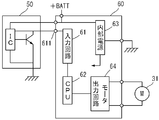
- FIG. 6 shows a detection sensor 50 and a control circuit 60 for the motor 31.
- the detection sensor 50 includes a known Hall IC, detects the through hole 211 as the platform 20 moves, and inputs the control circuit 60.
- a pulse signal shown in FIG. 9A is supplied to the terminal 611.
- the input circuit 61 of the control circuit 60 performs processing such as impedance conversion on the pulse signal received from the input terminal 611 and supplies it to a computer (CPU) 62.
- the CPU 62 operates the motor 31 through the motor output circuit 64 based on a program stored in advance.
- the internal power supply 63 converts the voltage from the battery (+ BATT) into a constant voltage necessary for each circuit in the control circuit 60 and supplies it to each circuit as a power supply.
- FIG. 7 shows an end detection routine for detecting whether or not the platform 20 is at the origin position and the extended end position.
- step S11 it is determined whether or not the output of the detection sensor 50 appearing at the input terminal 611 is at a high (Hi) level. If the output of the detection sensor 50 is at a high level and step S11 is affirmed, the time during which the output of the detection sensor 50 is maintained at a high level is counted in step S12. At the same time, in step S12, the count value of the counter that counts the time during which the output of the detection sensor 50 is maintained at the low (Lo) level is cleared.
- step S13 the time during which the output of the detection sensor 50 is maintained at the low level is counted and at the same time the output of the detection sensor 50 is high. Clear the count value of the counter that counts the time that the level is maintained.
- step S14 it is determined whether or not the output of the detection sensor 50 has changed from a low level to a high level. When the output of the detection sensor 50 changes from the low level to the high level, an affirmative determination is made in step S14, and the ratio of the time during which the output of the detection sensor 50 maintains the low level is calculated based on the following equation 1.
- step S16 both the counters that count the time during which the output of the detection sensor 50 is maintained at the high level and the low level are reclaimed.
- steps S17 and S18 it is determined whether or not the ratio of the time during which the low level calculated as described above has been maintained is less than 10% or more than 90%.
- Step S17 is affirmatively determined, and in step S19, the count value C of the position counter indicating the movement position of the platform 20 is set to a predetermined value D corresponding to the extended position. If it exceeds 90%, an affirmative determination is made in step S18, and the count value C of the position counter is set to zero corresponding to the origin position in step S20.
- step S14 when the output of the detection sensor 50 is changed from the low level to the high level, when the negative determination is made in step S14, and the ratio of the time during which the output of the detection sensor 50 is maintained at the low level is 10% to 90%. Also when both steps S17 and S18 are negatively determined, the processing of the end portion detection routine ends.
- FIG. 8 shows a motor control routine for controlling the motor 31.
- step S31 it is determined whether or not the output of the detection sensor 50 is a pulse edge that has changed from a low level to a high level, or a pulse edge that has changed from a high level to a low level. If it is the timing of any pulse edge and step S31 is affirmed, a storage switch (not shown) for storing the wheelchair lifter 10 including the platform 20 in the welfare vehicle B is operated in step S32. It is determined whether or not. If the storage switch is operated and the determination in step S32 is affirmative, the count value C of the position counter of the platform 20 is decremented in step S33 because storage is in progress.
- step S34 the count value C of the position counter of the platform 20 is incremented.
- the count value C is zero at the origin position, D at the exit position, and from the origin position to the exit position between both positions. It becomes a big value according to.
- step S35 the motor 31 is controlled with a duty ratio determined in advance according to the count value C of the position counter. As shown in FIG.
- the motor 31 when the platform 20 is near the origin position or near the extended position, the motor 31 is controlled with a duty ratio of about 10%, and the platform 20 is located near the origin position or the output. Control is performed such that the duty ratio is gradually increased as the distance from the vicinity of the end position increases.
- duty control in this way, when the platform 20 moves from the origin position to the exit position, or conversely, from the exit position to the origin position, the motor 31 starts to move, and the platform 20 starts to move at a low speed. As the speed increases, the speed is increased, and the low speed operation is resumed near the movement end position. Therefore, the wheelchair user who got on the platform 20 is not unstablely shaken by the sudden movement of the platform 20.
- step S35 When the processing of step S35 is completed, and when the output of the detection sensor 50 is neither a pulse edge that has changed from a low level to a high level or a pulse edge that has changed from a high level to a low level, but a negative determination is made in step S31, The process of the motor control routine ends.
- the platform 20 when the platform 20 is at the origin position and when it is at the extended position, it is detected separately according to the ratio of the low level time of the detection sensor 50, and the extended position is detected while the wheelchair lift 10 is deployed.
- the platform 20 is stopped at that position, and when the four-end link mechanism 43 of the wheelchair lift 10 is in the retracted position, the platform 20 is moved from that position to the retracted position. Then, when the platform 20 reaches the origin position, the storing operation of the platform 20 is stopped.
- the platform 20 can be appropriately controlled by distinguishing and detecting the origin position and the extended position of the platform 20.
- the configuration for distinguishing the two positions can be simply performed without changing the size of the through-holes, and without cost. it can.
- two through-holes having a size of about 0.1 times in the moving direction of the platform 20 with respect to the interval between the through-holes 211 are provided continuously. Since there is a possibility that detection leakage by the detection sensor 50 may occur due to the small size, a spare through hole is provided.
- the present invention is not limited to the appearance and configuration described in the above embodiment, and various modifications, additions, and deletions can be made without changing the gist of the present invention.
- the detection sensor an optical sensor or a pressure sensor may be employed.
- electric signals different from each other at each position electric signals having different signal levels and electric signals having different signal waveforms can be adopted.
- the shape changing portion a protrusion protruding toward the detection sensor 50 or a hole recessed in the opposite direction can be adopted.
Landscapes
- Health & Medical Sciences (AREA)
- Public Health (AREA)
- Life Sciences & Earth Sciences (AREA)
- Animal Behavior & Ethology (AREA)
- General Health & Medical Sciences (AREA)
- Veterinary Medicine (AREA)
- Power-Operated Mechanisms For Wings (AREA)
- Measurement Of Length, Angles, Or The Like Using Electric Or Magnetic Means (AREA)
- Transmission And Conversion Of Sensor Element Output (AREA)
Abstract
基体(48)に対して相対移動する移動物体(20)における互いに離れた2位置への移動を検出する位置検出構造において、互いに離れた2位置への移動物体の移動を単一のセンサで、誤検出なく区別して検出する。基体(ホルダ)(48)と移動物体(プラットホーム)(20)との対向部位の一方で、前記2位置のうちの一つの位置に検出センサ(50)を設け、該検出センサは、各位置において互いに異なった電気信号を発生する。一つの検出センサが2位置でそれぞれ異なった信号を発生するので、一つのセンサで2位置への移動物体の移動を区別して検出することができる。
Description
本発明は、基体に対して相対移動する移動物体における互いに離れた2位置への移動を検出する位置検出構造に関する。
かかる位置検出構造として、2位置に対応させてリミットスイッチをそれぞれ設けて2位置への移動を検出する構造が一般的である。この場合、リミットスイッチが2つ必要となる問題がある。
これに対し、2位置のうちの一つの位置を検出し、その位置を基準として相対移動距離に応じてパルスを発生させ、そのパルス数をカウントして、残りの一つの位置への移動を検出する構造が開発されている(下記特許文献1参照)。
これに対し、2位置のうちの一つの位置を検出し、その位置を基準として相対移動距離に応じてパルスを発生させ、そのパルス数をカウントして、残りの一つの位置への移動を検出する構造が開発されている(下記特許文献1参照)。
しかし、パルス数のカウントには誤検出もあり、上記特許文献1の位置検出法をアクチュエータ制御に適用すると、誤検出に基づいてアクチュエータ制御が行われ、各種トラブルの原因となる。例えば、アクチュエータとしてのモータのロック、不適切な位置でのアクチュエータ動作による不具合というような問題が生じる。
本発明は、このような問題に鑑み、一つの検出センサで2位置で互いに異なる信号を発生させることにより、互いに離れた2位置への移動物体の移動を単一のセンサで、誤検出なく区別して検出することを課題とする。
本発明は、このような問題に鑑み、一つの検出センサで2位置で互いに異なる信号を発生させることにより、互いに離れた2位置への移動物体の移動を単一のセンサで、誤検出なく区別して検出することを課題とする。
本発明の第1発明は、基体に対して相対移動する移動物体における互いに離れた2位置への移動を検出する位置検出構造であって、前記基体と前記移動物体との対向部位の一方で、前記2位置のうちの一つの位置に検出センサを設け、該検出センサは、各位置において互いに異なった電気信号を発生することを特徴とする位置検出構造である。
第1発明によれば、一つの検出センサが2位置でそれぞれ異なった信号を発生するので、一つのセンサで2位置への移動物体の移動を区別して検出することができる。
第1発明によれば、一つの検出センサが2位置でそれぞれ異なった信号を発生するので、一つのセンサで2位置への移動物体の移動を区別して検出することができる。
本発明の第2発明は、上記第1発明の位置検出構造において、前記検出センサは、前記対向部位の他方の形状変化を検出するものであり、前記対向部位の他方には、相対移動の方向に周期的に形状が変化する形状変化部が設けられ、該形状変化部は、前記2位置において相対移動方向の大きさが互いに異なる形状変化部が形成されていることを特徴とする位置検出構造である。
第2発明によれば、2位置間において形状変化部の形状の大きさを互いに異ならせて2位置を区別して検出するので、コストアップなしで誤作動なく位置検出できる。
第2発明によれば、2位置間において形状変化部の形状の大きさを互いに異ならせて2位置を区別して検出するので、コストアップなしで誤作動なく位置検出できる。
本発明の第3発明は、上記第2発明の位置検出構造において、前記検出センサは、磁気抵抗の変化を検出する磁気センサであり、形状変化部は、磁性体に貫通孔、突起又は穴が形成されたものであり、前記2位置において、相対移動の方向における貫通孔、突起又は穴の大きさが異なっていることを特徴とする位置検出構造である。
第3発明によれば、汎用の磁気センサによって、上記第1及び第2発明と同様の作用効果を達成できる。
第3発明によれば、汎用の磁気センサによって、上記第1及び第2発明と同様の作用効果を達成できる。
本発明の第4発明は、上記第3発明の位置検出構造において、前記2位置に設けられた形状変化部である貫通孔、突起又は穴の一方は、相対移動方向の大きさが小さく、しかも複数個が連続して設けられていることを特徴とする位置検出構造である。
第4発明によれば、検出センサによる一つの形状変化部の検出に失敗しても、連続する他の形状変化部を検出できるため、形状変化部の大きさが小さくても検出漏れの可能性を少なくすることができる。
第4発明によれば、検出センサによる一つの形状変化部の検出に失敗しても、連続する他の形状変化部を検出できるため、形状変化部の大きさが小さくても検出漏れの可能性を少なくすることができる。
以下、本発明の実施形態を図面を用いて説明する。
本実施形態に係る電動スライド装置30は、福祉車両Bの後部に設置された車椅子リフタ10において、プラットホーム20を格納位置(原点位置)と使用位置(出端位置)間で水平スライドさせる装置である。
ここで、図中における前後左右及び上下は車椅子リフタ10を備える福祉車両Bの前後左右及び上下に対応している。
本実施形態に係る電動スライド装置30は、福祉車両Bの後部に設置された車椅子リフタ10において、プラットホーム20を格納位置(原点位置)と使用位置(出端位置)間で水平スライドさせる装置である。
ここで、図中における前後左右及び上下は車椅子リフタ10を備える福祉車両Bの前後左右及び上下に対応している。
本実施形態に係る電動スライド装置30について説明する前に福祉車両B及び車椅子リフタ10の概要について説明する。
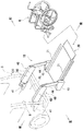
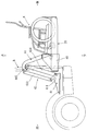
前記福祉車両Bは、図1等に示すように、ワンボックスタイプの車両で後側開口部Hを備えており、その後側開口部Hがバックドア(図示省略)によって開閉可能に構成されている。そして、前記福祉車両Bの後部に、乗員を車椅子Kで後側開口部Hから乗降させるための車椅子リフタ10が設けられている。
車椅子リフタ10は、車椅子Kを載せる水平なプラットホーム20と、そのプラットホーム20を昇降させる左右一対の昇降リンク機構40と、前記プラットホーム20を前後スライドさせる電動スライド装置30(図4参照)とから構成されている。
前記福祉車両Bは、図1等に示すように、ワンボックスタイプの車両で後側開口部Hを備えており、その後側開口部Hがバックドア(図示省略)によって開閉可能に構成されている。そして、前記福祉車両Bの後部に、乗員を車椅子Kで後側開口部Hから乗降させるための車椅子リフタ10が設けられている。
車椅子リフタ10は、車椅子Kを載せる水平なプラットホーム20と、そのプラットホーム20を昇降させる左右一対の昇降リンク機構40と、前記プラットホーム20を前後スライドさせる電動スライド装置30(図4参照)とから構成されている。
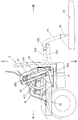
昇降リンク機構40は、図1から図3に示すように、車室フロアFLの後部両端(左右)に設けられた固定金具41と、左右の前記固定金具41にそれぞれ上下回動可能な状態で連結された四節リンク機構43と、その四節リンク機構43の先端側に同じく上下回動可能な状態で連結された起立状態の昇降アーム44と、前記四節リンク機構43を上下回動させて、昇降アーム44を昇降させる油圧シリンダ(図示省略)とから構成されている。
なお、図1はカバー430に覆われた状態の四節リンク機構43を表しており、図2、図3はカバー430を省略した状態の四節リンク機構43を表している。
四節リンク機構43は、四隅に相対回動可能な連結点(支点)を備えるリンク機構であり、図2、図3に示すように、固定金具41のリンク支持部411と、上部リンク433と、下部リンク434と、昇降アーム44のリンク支持部445とから構成されている。そして、前記油圧シリンダの動作により、四節リンク機構43が上下回動することで、昇降アーム44が起立姿勢のままで昇降するようになる。
なお、図1はカバー430に覆われた状態の四節リンク機構43を表しており、図2、図3はカバー430を省略した状態の四節リンク機構43を表している。
四節リンク機構43は、四隅に相対回動可能な連結点(支点)を備えるリンク機構であり、図2、図3に示すように、固定金具41のリンク支持部411と、上部リンク433と、下部リンク434と、昇降アーム44のリンク支持部445とから構成されている。そして、前記油圧シリンダの動作により、四節リンク機構43が上下回動することで、昇降アーム44が起立姿勢のままで昇降するようになる。
左右の昇降アーム44の下端部には、図1~図3に示すように、ホルダ48が設けられており、左右のホルダ48にプラットホーム20が前後スライド可能な状態で支持されている。そして、プラットホーム20の左右両側には土手21が形成されており、前記ホルダ48とプラットホーム20の土手21間に、そのプラットホーム20をホルダ48に対して前後スライドさせる電動スライド装置30(図4参照)が設けられている。
電動スライド装置30は、ラック&ピニオンの噛合作用を利用してプラットホーム20をホルダ48に対して前後スライドさせる装置であり、図4に示すように、モータ31と、歯車減速器33と、ラック34と、ピニオンギヤ35とから構成されている。
モータ31、歯車減速器33は、ホルダ48内に配置され、ラック34は土手21内に固定されている。従って、モータ31を回転駆動させて歯車減速器33を介してピニオンギヤ35を作動させると、ピニオンギヤ35とラック34との噛合位置が変化し、ホルダ48とプラットホーム20とが相対移動することになる。ここでは、ホルダ48が本発明における基体に相当し、プラットホーム20が移動物体に相当する。
電動スライド装置30は、ラック&ピニオンの噛合作用を利用してプラットホーム20をホルダ48に対して前後スライドさせる装置であり、図4に示すように、モータ31と、歯車減速器33と、ラック34と、ピニオンギヤ35とから構成されている。
モータ31、歯車減速器33は、ホルダ48内に配置され、ラック34は土手21内に固定されている。従って、モータ31を回転駆動させて歯車減速器33を介してピニオンギヤ35を作動させると、ピニオンギヤ35とラック34との噛合位置が変化し、ホルダ48とプラットホーム20とが相対移動することになる。ここでは、ホルダ48が本発明における基体に相当し、プラットホーム20が移動物体に相当する。
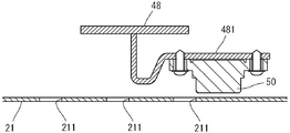
図4、5に示すように、ホルダ48の内壁面には検出センサ50としての磁気センサがブラケット481によって設けられ、検出センサ50の検出端が、プラットホーム20の土手21の壁面に対向配置されている。その土手21の壁面にはプラットホーム20の移動方向に一定の間隔を置いて複数の貫通孔211が設けられている。このように検出センサ50と貫通孔211が対向配置されていることにより、ホルダ48とプラットホーム20とが相対移動すると、貫通孔211の有無を検出センサ50が検知して、上記相対移動を検出することができる。ここで、ホルダ48と土手21が、本発明における対向部位の一方と他方に相当し、貫通孔211が形状変化部に相当する。
図9のBには、プラットホーム20が原点位置から出端位置まで移動する間の貫通孔211の配置の様子が示されている。原点位置と出端位置の間には一定間隔で同じ大きさの貫通孔が形成され、原点位置には、貫通孔211同士の間隔よりもプラットホーム20の移動方向に約10倍の大きさの貫通孔が開けられ、出端位置には、貫通孔211同士の間隔よりもプラットホーム20の移動方向に約0.1倍の大きさの貫通孔が2個続けて開けられている。なお、図9のBでは貫通孔211の大きさを正確に表示していない。また、図4では図面を見易くするために貫通孔211の一部のみを示している。
図6には検出センサ50及びモータ31の制御回路60が示されており、検出センサ50は公知のホールICから成り、プラットホーム20の移動に伴って貫通孔211を検知して制御回路60の入力端子611に図9のAに示すパルス信号を供給する。制御回路60の入力回路61は、入力端子611から受けたパルス信号をインピーダンス変換等の処理をしてコンピュータ(CPU)62に供給する。CPU62は、予め格納されたプログラムに基づいてモータ出力回路64を通じてモータ31を作動させる。内部電源63はバッテリ(+BATT)からの電圧を制御回路60内の各回路に必要な一定電圧に変換して各回路に電源として供給する。
CPU62による処理プログラムを図7、8に基づいて説明する。
図7は、プラットホーム20が原点位置及び出端位置にあるか否かを検出する端部検出ルーチンを示している。ステップS11では、入力端子611に表れる検出センサ50の出力がハイ(Hi)レベルにあるか否かが判定される。検出センサ50の出力がハイレベルであり、ステップS11が肯定判断されると、ステップS12において検出センサ50の出力がハイレベルを維持している時間をカウントする。同時にステップS12では、検出センサ50の出力がロウ(Lo)レベルを維持している時間をカウントするカウンタのカウント値をクリアする。一方、検出センサ50の出力がロウレベルであり、ステップS11が否定判断されると、ステップS13において、検出センサ50の出力がロウレベルを維持している時間をカウントすると同時に、検出センサ50の出力がハイレベルを維持している時間をカウントするカウンタのカウント値をクリアする。
ステップS14では、検出センサ50の出力がロウレベルからハイレベルに変化したか否かが判定される。検出センサ50の出力がロウレベルからハイレベルに変化したときには、ステップS14は肯定判断され、検出センサ50の出力がロウレベルを維持している時間の割合が次の数式1に基づいて算出される。

次のステップS16では、検出センサ50の出力がハイレベル、及びロウレベルを維持している時間をカウントするカウンタが共にリクアされる。ステップS17、18では、上述のように算出されたロウレベルを維持していた時間の割合が10%未満か否か、或いは90%を超えているか否かが判定され、10%未満である場合は、ステップS17が肯定判断され、ステップS19においてプラットホーム20の移動位置を表す位置カウンタのカウント値Cを、出端位置に相当する所定値Dとする。また、90%を超えている場合は、ステップS18が肯定判断され、ステップS20において位置カウンタのカウント値Cを原点位置に相当するゼロとする。
ステップS19、S20の処理が終了すると、端部検出ルーチンの処理は終了する。また、検出センサ50の出力がロウレベルからハイレベルに変化したとき以外で、ステップS14が否定判断された場合、及び検出センサ50の出力がロウレベルを維持していた時間の割合が10%~90%の間でステップS17、S18が共に否定判断された場合も、端部検出ルーチンの処理は終了する。
図7は、プラットホーム20が原点位置及び出端位置にあるか否かを検出する端部検出ルーチンを示している。ステップS11では、入力端子611に表れる検出センサ50の出力がハイ(Hi)レベルにあるか否かが判定される。検出センサ50の出力がハイレベルであり、ステップS11が肯定判断されると、ステップS12において検出センサ50の出力がハイレベルを維持している時間をカウントする。同時にステップS12では、検出センサ50の出力がロウ(Lo)レベルを維持している時間をカウントするカウンタのカウント値をクリアする。一方、検出センサ50の出力がロウレベルであり、ステップS11が否定判断されると、ステップS13において、検出センサ50の出力がロウレベルを維持している時間をカウントすると同時に、検出センサ50の出力がハイレベルを維持している時間をカウントするカウンタのカウント値をクリアする。
ステップS14では、検出センサ50の出力がロウレベルからハイレベルに変化したか否かが判定される。検出センサ50の出力がロウレベルからハイレベルに変化したときには、ステップS14は肯定判断され、検出センサ50の出力がロウレベルを維持している時間の割合が次の数式1に基づいて算出される。
次のステップS16では、検出センサ50の出力がハイレベル、及びロウレベルを維持している時間をカウントするカウンタが共にリクアされる。ステップS17、18では、上述のように算出されたロウレベルを維持していた時間の割合が10%未満か否か、或いは90%を超えているか否かが判定され、10%未満である場合は、ステップS17が肯定判断され、ステップS19においてプラットホーム20の移動位置を表す位置カウンタのカウント値Cを、出端位置に相当する所定値Dとする。また、90%を超えている場合は、ステップS18が肯定判断され、ステップS20において位置カウンタのカウント値Cを原点位置に相当するゼロとする。
ステップS19、S20の処理が終了すると、端部検出ルーチンの処理は終了する。また、検出センサ50の出力がロウレベルからハイレベルに変化したとき以外で、ステップS14が否定判断された場合、及び検出センサ50の出力がロウレベルを維持していた時間の割合が10%~90%の間でステップS17、S18が共に否定判断された場合も、端部検出ルーチンの処理は終了する。
図8は、モータ31の制御を行うモータ制御ルーチンを示している。ステップS31では、検出センサ50の出力がロウレベルからハイレベルに変化したパルスエッジ、又はハイレベルからロウレベルに変化したパルスエッジか否かが判定される。いずれかのパルスエッジのタイミングであり、ステップS31が肯定判断されると、ステップS32では、プラットホーム20を含む車椅子リフタ10を福祉車両B内へ格納させるための格納スイッチ(図示省略)が操作されているか否か判定される。格納スイッチが操作されており、ステップS32が肯定判断されると、格納中であるためステップS33においてプラットホーム20の位置カウンタのカウント値Cをデクリメントする。また、格納スイッチが操作されておらず、従って、プラットホーム20を含む車椅子リフタ10を福祉車両B内から展開させる展開スイッチ(図示省略)が操作されていてステップS32が否定判断されるときは、展開中であるためステップS34においてプラットホーム20の位置カウンタのカウント値Cをインクリメントする。
図7及び図8のフローチャートのように位置カウンタのカウント値Cが処理されることにより、カウント値Cは原点位置でゼロ、出端位置でD、両位置間で原点位置から出端位置に向かうに従って大きな値となる。
次のステップS35では、位置カウンタのカウント値Cに応じて予め決められたデューティ比でモータ31を制御する。かかる制御は、図9のCに示されるように、プラットホーム20が原点位置付近、或いは出端位置付近では、10%程度のデューティ比でモータ31が制御され、プラットホーム20が原点位置付近、或いは出端位置付近から離れるに従って徐々にデューティ比が大きくされるように制御される。
このようにデューティ制御されることにより、プラットホーム20が原点位置から出端位置、或いは反対に出端位置から原点位置へ移動するとき、移動し始めはモータ31、プラットホーム20は低速で動き始め、移動するに従って高速となり、移動終了位置付近では再び低速作動となる。そのため、プラットホーム20に乗った車椅子利用者がプラットホーム20の急な動きで不安定に揺れ動かされることがなくなる。
ステップS35の処理が終了したとき、及び検出センサ50の出力がロウレベルからハイレベルに変化したパルスエッジ、又はハイレベルからロウレベルに変化したパルスエッジのいずれでもなく、ステップS31が否定判断されたとき、モータ制御ルーチンの処理は終了する。
図7及び図8のフローチャートのように位置カウンタのカウント値Cが処理されることにより、カウント値Cは原点位置でゼロ、出端位置でD、両位置間で原点位置から出端位置に向かうに従って大きな値となる。
次のステップS35では、位置カウンタのカウント値Cに応じて予め決められたデューティ比でモータ31を制御する。かかる制御は、図9のCに示されるように、プラットホーム20が原点位置付近、或いは出端位置付近では、10%程度のデューティ比でモータ31が制御され、プラットホーム20が原点位置付近、或いは出端位置付近から離れるに従って徐々にデューティ比が大きくされるように制御される。
このようにデューティ制御されることにより、プラットホーム20が原点位置から出端位置、或いは反対に出端位置から原点位置へ移動するとき、移動し始めはモータ31、プラットホーム20は低速で動き始め、移動するに従って高速となり、移動終了位置付近では再び低速作動となる。そのため、プラットホーム20に乗った車椅子利用者がプラットホーム20の急な動きで不安定に揺れ動かされることがなくなる。
ステップS35の処理が終了したとき、及び検出センサ50の出力がロウレベルからハイレベルに変化したパルスエッジ、又はハイレベルからロウレベルに変化したパルスエッジのいずれでもなく、ステップS31が否定判断されたとき、モータ制御ルーチンの処理は終了する。
以上の実施形態では、プラットホーム20が原点位置にあるとき、及び出端位置にあるときが、検出センサ50のロウレベル時間の割合によってそれぞれ区別して検出され、車椅子リフト10を展開中に出端位置が検出されたときには、その位置でプラットホーム20を停止させ、車椅子リフト10の四節リンク機構43が格納位置にあるときに出端位置が検出されているときには、その位置からプラットホーム20を格納位置に動作させ、その後プラットホーム20が原点位置に達すると、プラットホーム20の格納動作が停止される。このようにプラットホーム20の原点位置と出端位置とが区別して検出されることによってプラットホーム20を適切に制御することができる。しかも、2位置を検出するにも関わらず、検出センサ50は一つのみで済み、2位置を区別するための構成は貫通孔の大きさを変えるのみで良く、コストをかけずに簡単に実施できる。
なお、出端位置の検出のため、貫通孔211同士の間隔に対しプラットホーム20の移動方向に約0.1倍の大きさの貫通孔を2個続けて設けているが、これは貫通孔の大きさが小さいことにより検出センサ50による検出漏れが発生する可能性があるため、予備の貫通孔を設けているものである。
なお、出端位置の検出のため、貫通孔211同士の間隔に対しプラットホーム20の移動方向に約0.1倍の大きさの貫通孔を2個続けて設けているが、これは貫通孔の大きさが小さいことにより検出センサ50による検出漏れが発生する可能性があるため、予備の貫通孔を設けているものである。
本発明は、上記実施形態で説明した外観、構成に限定されず、本発明の要旨を変更しない範囲で種々の変更、追加、削除が可能である。例えば、
1.検出センサとして、光センサ、圧力センサを採用して構成することもできる。
2.各位置における互いに異なった電気信号として、信号レベルが異なる電気信号、信号波形が異なる電気信号を採用して構成することもできる。
3.形状変化部としては、検出センサ50に向けて突出した突起、或いはその反対に窪んだ穴を採用することもできる。
1.検出センサとして、光センサ、圧力センサを採用して構成することもできる。
2.各位置における互いに異なった電気信号として、信号レベルが異なる電気信号、信号波形が異なる電気信号を採用して構成することもできる。
3.形状変化部としては、検出センサ50に向けて突出した突起、或いはその反対に窪んだ穴を採用することもできる。
10 車椅子リフタ
20 プラットホーム(移動物体)
21 土手
211 貫通孔(形状変化部)
30 電動スライド装置
31 モータ
34 ラック
35 ピニオンギヤ
40 昇降リンク機構
43 四節リンク機構
44 昇降アーム
48 ホルダ(基体)
50 検出センサ
60 制御回路
20 プラットホーム(移動物体)
21 土手
211 貫通孔(形状変化部)
30 電動スライド装置
31 モータ
34 ラック
35 ピニオンギヤ
40 昇降リンク機構
43 四節リンク機構
44 昇降アーム
48 ホルダ(基体)
50 検出センサ
60 制御回路
Claims (4)
- 基体に対して相対移動する移動物体における互いに離れた2位置への移動を検出する位置検出構造であって、前記基体と前記移動物体との対向部位の一方で、前記2位置のうちの一つの位置に検出センサを設け、該検出センサは、各位置において互いに異なった電気信号を発生することを特徴とする位置検出構造。
- 請求項1の位置検出構造において、前記検出センサは、前記対向部位の他方の形状変化を検出するものであり、前記対向部位の他方には、相対移動の方向に周期的に形状が変化する形状変化部が設けられ、該形状変化部は、前記2位置において相対移動方向の大きさが互いに異なる形状変化部が形成されていることを特徴とする位置検出構造。
- 請求項2の位置検出構造において、前記検出センサは、磁気抵抗の変化を検出する磁気センサであり、形状変化部は、磁性体に貫通孔、突起又は穴が形成されたものであり、前記2位置において、相対移動の方向における貫通孔、突起又は穴の大きさが異なっていることを特徴とする位置検出構造。
- 請求項3の位置検出構造において、前記2位置に設けられた形状変化部である貫通孔、突起又は穴の一方は、相対移動方向の大きさが小さく、しかも複数個が連続して設けられていることを特徴とする位置検出構造。
Applications Claiming Priority (2)
| Application Number | Priority Date | Filing Date | Title |
|---|---|---|---|
| JP2011056284A JP2012193973A (ja) | 2011-03-15 | 2011-03-15 | 位置検出構造 |
| JP2011-056284 | 2011-03-15 |
Publications (1)
| Publication Number | Publication Date |
|---|---|
| WO2012124357A1 true WO2012124357A1 (ja) | 2012-09-20 |
Family
ID=46830438
Family Applications (1)
| Application Number | Title | Priority Date | Filing Date |
|---|---|---|---|
| PCT/JP2012/050308 Ceased WO2012124357A1 (ja) | 2011-03-15 | 2012-01-11 | 位置検出構造 |
Country Status (2)
| Country | Link |
|---|---|
| JP (1) | JP2012193973A (ja) |
| WO (1) | WO2012124357A1 (ja) |
Cited By (1)
| Publication number | Priority date | Publication date | Assignee | Title |
|---|---|---|---|---|
| CN115335946A (zh) * | 2020-04-03 | 2022-11-11 | Ls电气株式会社 | 用于连续检测引入引出位置的电力设备 |
Citations (4)
| Publication number | Priority date | Publication date | Assignee | Title |
|---|---|---|---|---|
| JPH06323804A (ja) * | 1993-04-22 | 1994-11-25 | Honeywell Inc | 位置センサ |
| JP2002022402A (ja) * | 2000-05-24 | 2002-01-23 | Balluff Gmbh | 位置測定システム |
| JP2002139347A (ja) * | 2000-11-01 | 2002-05-17 | Yaskawa Electric Corp | 磁気式エンコーダ |
| JP2004012305A (ja) * | 2002-06-07 | 2004-01-15 | Tachi S Co Ltd | スライドシートのスライド位置検出方法およびスライド位置検出装置 |
-
2011
- 2011-03-15 JP JP2011056284A patent/JP2012193973A/ja not_active Withdrawn
-
2012
- 2012-01-11 WO PCT/JP2012/050308 patent/WO2012124357A1/ja not_active Ceased
Patent Citations (4)
| Publication number | Priority date | Publication date | Assignee | Title |
|---|---|---|---|---|
| JPH06323804A (ja) * | 1993-04-22 | 1994-11-25 | Honeywell Inc | 位置センサ |
| JP2002022402A (ja) * | 2000-05-24 | 2002-01-23 | Balluff Gmbh | 位置測定システム |
| JP2002139347A (ja) * | 2000-11-01 | 2002-05-17 | Yaskawa Electric Corp | 磁気式エンコーダ |
| JP2004012305A (ja) * | 2002-06-07 | 2004-01-15 | Tachi S Co Ltd | スライドシートのスライド位置検出方法およびスライド位置検出装置 |
Cited By (2)
| Publication number | Priority date | Publication date | Assignee | Title |
|---|---|---|---|---|
| CN115335946A (zh) * | 2020-04-03 | 2022-11-11 | Ls电气株式会社 | 用于连续检测引入引出位置的电力设备 |
| CN115335946B (zh) * | 2020-04-03 | 2026-04-28 | Ls电气株式会社 | 用于连续检测引入引出位置的电力设备 |
Also Published As
| Publication number | Publication date |
|---|---|
| JP2012193973A (ja) | 2012-10-11 |
Similar Documents
| Publication | Publication Date | Title |
|---|---|---|
| JP6714365B2 (ja) | スイッチ装置 | |
| CN101274585B (zh) | 外滑式天窗装置 | |
| JP2012144923A (ja) | パワーウインドウ装置 | |
| JP2018525270A (ja) | 自動車の電動調整可能な積載空間装置のための制御システム | |
| US20160282960A1 (en) | Movable device | |
| JP6062890B2 (ja) | 射出成形機の樹脂飛散防止カバー | |
| JP6905887B2 (ja) | 車両用操作検出装置及びスライドドア装置 | |
| JP2012193973A (ja) | 位置検出構造 | |
| JP2005314949A (ja) | パワーウィンド用安全装置 | |
| US20220388377A1 (en) | Control device | |
| JP2006304866A (ja) | 車両用昇降装置 | |
| JP2008260455A (ja) | 可動体装置 | |
| CN110029906B (zh) | 车辆用操作检测装置 | |
| CN113356720A (zh) | 汽车车窗的控制装置和方法 | |
| JP2011068183A (ja) | バックル装置及びそれを用いたシートベルト装置 | |
| JP2017128936A (ja) | 車両用挟み込み防止装置 | |
| JP4973951B2 (ja) | 車両用昇降装置 | |
| KR100773887B1 (ko) | 모니터가 승강하는 컴퓨터 책상 | |
| US10550620B2 (en) | Pinching detection sensor | |
| JP5446389B2 (ja) | 車両用シート駆動装置 | |
| JP2013170391A (ja) | 車両用開閉体制御装置 | |
| WO2008072729A1 (ja) | 電動補助装置 | |
| JP2017025580A (ja) | 開閉制御装置 | |
| JP2022061790A (ja) | 車両用操作検出装置 | |
| JP2006151013A (ja) | 車両用容器収納装置 |
Legal Events
| Date | Code | Title | Description |
|---|---|---|---|
| 121 | Ep: the epo has been informed by wipo that ep was designated in this application |
Ref document number: 12758172 Country of ref document: EP Kind code of ref document: A1 |
|
| NENP | Non-entry into the national phase |
Ref country code: DE |
|
| 122 | Ep: pct application non-entry in european phase |
Ref document number: 12758172 Country of ref document: EP Kind code of ref document: A1 |