WO2012124234A1 - 睡眠評価装置および睡眠評価方法 - Google Patents
睡眠評価装置および睡眠評価方法 Download PDFInfo
- Publication number
- WO2012124234A1 WO2012124234A1 PCT/JP2011/079518 JP2011079518W WO2012124234A1 WO 2012124234 A1 WO2012124234 A1 WO 2012124234A1 JP 2011079518 W JP2011079518 W JP 2011079518W WO 2012124234 A1 WO2012124234 A1 WO 2012124234A1
- Authority
- WO
- WIPO (PCT)
- Prior art keywords
- display
- sleep
- state
- period
- unit
- Prior art date
Links
Images


Classifications
-
- A—HUMAN NECESSITIES
- A61—MEDICAL OR VETERINARY SCIENCE; HYGIENE
- A61B—DIAGNOSIS; SURGERY; IDENTIFICATION
- A61B5/00—Measuring for diagnostic purposes; Identification of persons
- A61B5/48—Other medical applications
- A61B5/4806—Sleep evaluation
- A61B5/4809—Sleep detection, i.e. determining whether a subject is asleep or not
-
- A—HUMAN NECESSITIES
- A61—MEDICAL OR VETERINARY SCIENCE; HYGIENE
- A61B—DIAGNOSIS; SURGERY; IDENTIFICATION
- A61B5/00—Measuring for diagnostic purposes; Identification of persons
- A61B5/48—Other medical applications
- A61B5/4806—Sleep evaluation
- A61B5/4812—Detecting sleep stages or cycles
-
- A—HUMAN NECESSITIES
- A61—MEDICAL OR VETERINARY SCIENCE; HYGIENE
- A61B—DIAGNOSIS; SURGERY; IDENTIFICATION
- A61B5/00—Measuring for diagnostic purposes; Identification of persons
- A61B5/08—Detecting, measuring or recording devices for evaluating the respiratory organs
-
- A—HUMAN NECESSITIES
- A61—MEDICAL OR VETERINARY SCIENCE; HYGIENE
- A61B—DIAGNOSIS; SURGERY; IDENTIFICATION
- A61B5/00—Measuring for diagnostic purposes; Identification of persons
- A61B5/103—Detecting, measuring or recording devices for testing the shape, pattern, colour, size or movement of the body or parts thereof, for diagnostic purposes
- A61B5/11—Measuring movement of the entire body or parts thereof, e.g. head or hand tremor, mobility of a limb
-
- A—HUMAN NECESSITIES
- A61—MEDICAL OR VETERINARY SCIENCE; HYGIENE
- A61B—DIAGNOSIS; SURGERY; IDENTIFICATION
- A61B5/00—Measuring for diagnostic purposes; Identification of persons
- A61B5/74—Details of notification to user or communication with user or patient ; user input means
- A61B5/742—Details of notification to user or communication with user or patient ; user input means using visual displays
Definitions
- the present invention relates to a sleep evaluation apparatus and a sleep evaluation method.
- Patent Document 1 Japanese Patent Laid-Open No. 2007-319238 discloses a technique for measuring a temporal change in sleep depth and displaying the measurement result in a graph.
- Patent Document 2 Japanese Unexamined Patent Application Publication No. 2009-22671 discloses a technique for displaying a measurement result of biological information such as blood pressure for 12 hours in the form of a radar chart.
- the present invention has been conceived in view of such circumstances, and an object thereof is to display a measurement result in an easily understandable manner in the sleep evaluation apparatus.
- the sleep evaluation apparatus includes a body motion detection unit for detecting a body motion of a measurement subject on the bed and a measurement subject in the first period based on a detection result of the body motion detection unit. Based on the determination result by the first determination means and the first determination means, whether the sleep state or the awake state for each second period longer than the first period A second discriminating unit for discriminating; and a display unit for displaying the discrimination result by the second discriminating unit on the display device. The display unit sleeps based on the discrimination result by the second discriminating unit. Information on the occurrence of mid-wake in the state is further displayed on the display device.
- the information on the occurrence of mid-wake is at least the time or number of occurrences of mid-wake in the sleep state.
- the display unit displays a plurality of display units arranged in a circle on the display device, and the determination result by the second determination unit is displayed on the display unit while the display units correspond to a certain period. Use to display.
- the display unit is different from the display unit corresponding to the period determined as one of the sleep state and the awake state and the display unit corresponding to the period determined as the other state. Display in display mode.
- the display means turns on and displays the display unit corresponding to the period determined as one of the sleep state and the awake state, and blinks the display unit corresponding to the period determined as the other state. Display.
- the first determining means determines the sleep state of the measurement subject for each first period for a specific period longer than the first and second periods, and the display means is the first period in the specific period.
- the accumulated time of either the sleeping state or the awakening state according to the discrimination result by the discrimination means of 2 is further displayed on the display device.
- the second discriminating unit further discriminates the wake-up state of the measurement subject based on the discrimination result by the first discrimination unit, and the display unit discriminates the wake-up state of the measurement subject by the second discrimination unit.
- the display device displays information related to the occurrence of awakening in the sleep state.
- the information processing apparatus further includes an input unit that receives an input of information specifying the end of a specific period, and the display unit includes information related to the occurrence of an awakening in the sleep state on the display device in response to an input to the input unit. Is displayed.
- the apparatus further comprises detection means for detecting the occurrence of snoring of the person to be measured, and the display means detects the occurrence of snoring in the display device when the detection means further detects the snoring of the person to be measured.
- detection means for detecting the occurrence of snoring of the person to be measured
- the display means detects the occurrence of snoring in the display device when the detection means further detects the snoring of the person to be measured.
- the display means further causes the display device to display the determination result by the first determination means.
- a sleep evaluation method is a sleep evaluation method executed in a sleep evaluation apparatus including a body motion detection unit for detecting a body motion of a measurement subject on a bed, the body motion detection unit Based on the detection result, the step of determining the sleep state of the person to be measured in the first period and the sleep state for each second period longer than the first period based on the determination result in the first period Determining whether or not the user is in the awake state, displaying the determination result in the second period on the display device, and generating the awakening in the sleep state based on the determination result in the second period Displaying information on the display device.
- the distinction between the sleep state and the awake state is displayed, and further, information related to the occurrence of the awakening is displayed based on the discrimination result of the sleep type in the sleep state.
- the distinction between the sleep state and the wakefulness state is displayed at regular intervals, so that it is possible to display the sleep state and the wakefulness state and information related to the occurrence of the wakefulness in a smaller display area.
- FIG. 1 It is a figure which shows the specific example of the external appearance of the sleep level evaluation apparatus (henceforth an evaluation apparatus) as a sleep evaluation apparatus concerning this Embodiment. It is the schematic showing the side surface of the evaluation apparatus. It is the schematic of the external appearance seen from diagonally upward of the evaluation apparatus. It is a block diagram which shows the specific example of the hardware constitutions of an evaluation apparatus. It is a figure explaining the usage example of an evaluation apparatus. It is a block diagram which shows the specific example of the function structure for discrimination
- (A) is a figure which shows the specific example of the respiration waveform isolate
- (B) is the specific example of the body movement waveform separated from the waveform represented in FIG. It is a figure which shows an example.
- (A) is a figure which shows the specific example of the discrimination
- (B) is a figure which shows the specific example of correction
- (C) is a figure showing the specific example of the discrimination
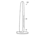
- FIG. 1 is a diagram showing a specific example of the appearance of a sleep level evaluation apparatus (hereinafter abbreviated as an evaluation apparatus) 100 according to the present embodiment.
- FIG. 2 is a schematic diagram showing a side surface of the evaluation apparatus 100
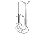
- FIG. 3 is a schematic diagram of an appearance viewed obliquely from above.
- evaluation apparatus 100 has an external appearance in which a rectangular parallelepiped or a vertically long casing processed with rounded corners is set up with respect to a pedestal.
- a button group 10 for operation is provided on the surface of the pedestal, and a display unit 20 is provided on the surface of the casing standing on the pedestal.
- the sensor 30 and the control unit 40 are included in the housing.
- the surface of the housing on which the display unit 20 is provided is also referred to as the front of the evaluation apparatus 100.
- the evaluation apparatus 100 includes a communication unit 50 for performing wireless or wired communication.
- the communication part 50 is provided from the edge part on the opposite side to the base of a housing
- the communication unit 50 is used to connect to a display device 200 such as a personal computer (hereinafter referred to as a PC) or a mobile phone, and output display data to the display device 200.
- a display device 200 such as a personal computer (hereinafter referred to as a PC) or a mobile phone
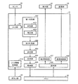
- FIG. 4 is a block diagram illustrating a specific example of the hardware configuration of the evaluation apparatus 100.
- button group 10, sensor 30, display unit 20, and communication unit 50 are all connected to control unit 40.
- the button group 10 outputs an operation signal to the control unit 40 when operated by the measurement subject.
- the sensor 30 includes a body motion sensor 31 and a microphone (hereinafter abbreviated as “microphone”) 32 as an example of a voice sensor, and each outputs a sensor signal to the control unit 40.
- a Doppler sensor is preferably used as the body motion sensor 31 . In the following description, it is assumed that the body motion sensor 31 is a Doppler sensor. In addition, an ultrasonic sensor or an infrared sensor may be used.
- the body motion sensor 31 which is a Doppler sensor, includes an output unit for outputting radio waves for measurement and a receiving unit.
- the receiving unit receives a radio wave reflected from the surface of the object to be measured among the radio waves output from the output unit, and outputs a sensor signal corresponding to a change in frequency from the output radio wave.
- the body movement sensor 31 replaces with the body movement sensor 31 as a mechanism which detects a body movement, a camera may be provided, and a body movement may be detected by performing an image analysis in the control part 40.
- the control unit 40 includes a CPU 41 for performing overall control and a memory 42 for storing programs executed by the CPU 41.
- the CPU 41 executes a display program stored in the memory 42, performs calculations using the input operation signals and sensor signals, calculates a sleep level described later, and sleeps. Display data for displaying the level of the current level is generated. Moreover, the control part 40 performs various processes, such as calculation of the sleep latency time mentioned later.
- the control unit 40 executes display control for performing screen display on the display unit 20 based on the display data. Furthermore, communication control for transmitting display data from the communication unit 50 to the display device 200 is executed.
- the communication unit 50 may directly communicate with the display device 200 through wireless communication such as infrared communication or communication using Bluetooth (registered trademark), or may have an Internet connection function to connect the Internet. It may communicate with the display device 200 via the network.
- wireless communication such as infrared communication or communication using Bluetooth (registered trademark)
- Bluetooth registered trademark
- the communication unit 50 has a wireless LAN (Local Area Network) server function, and is expressed in a markup language such as HTML (Hyper Text Markup Language) for the display device 200 accessed through the wireless LAN connection.
- a markup language such as HTML (Hyper Text Markup Language)
- display data to be described later may be transmitted.
- the evaluation apparatus 100 is provided with a timer 60.
- the timer 60 is connected to the control unit 40.
- the CPU 41 acquires time information from the timer 60, specifies each time such as an entrance time described later, and stores it in the memory 42.
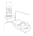
- FIG. 5 is a diagram for explaining an example of use of the evaluation apparatus 100.
- evaluation apparatus 100 is installed in the vicinity (for example, a bedside) of a measurement subject who is sleeping. By performing the measurement operation in this state, radio waves are output from the body motion sensor 31 that is a Doppler sensor.
- the radio wave output from the body motion sensor 31 mainly reaches the chest, shoulder, etc. of the person under sleep, and the change in the frequency of the reflected wave is output to the control unit 40 as a sensor signal. . Based on this change in frequency, the control unit 40 detects body movements such as chest movements and rollovers of the person being measured while sleeping, and determines the sleep level based on the detection results.
- the sound near the person to be measured is detected by the microphone 32 that is a voice sensor.
- the audio signal is output to the control unit 40 as a sensor signal.
- This sensor signal is also referred to as a sound signal in the following description.
- the control unit 40 detects body movements such as chest movements and rolling of the measurement subject who is sleeping based on the change in frequency represented by the breathing / body movement signal, and determines the sleep state based on the detection result. Determine. In addition, the control unit 40 detects “snoring” of the measurement subject from the sound signal, and determines the state of snoring based on the detection result.
- FIG. 6 is a block diagram illustrating a specific example of a functional configuration for determining a sleep level, which is an example of determining whether the evaluation apparatus 100 is in a sleep state or an awake state.
- Each function shown in FIG. 6 is formed on the CPU 41 by the CPU 41 executing a program stored in the memory 42, but at least a part thereof is formed by a hardware configuration such as an electric circuit. May be.
- evaluation apparatus 100 has an input unit 401 for receiving an input of a sensor signal from sensor 30, and a first determination unit 402 for determining a sleep state of a unit period based on the sensor signal. And a second discriminating unit 409 for discriminating the level of the sleep state for a predetermined period in which the unit period continues for a predetermined number based on the discrimination result for each unit period, and the constant based on the level of the sleep state
- a determination unit 403 for determining a display mode of a period, a generation unit 404 for generating display data for displaying a sleep level based on the determined display mode, and a process of storing the display data in the memory 42
- a storage unit 405 for executing, a reading unit 406 for reading display data from the memory 42, and a process for displaying the read display data on the display unit 20
- a display control unit 407, and a communication control unit 408 for executing processing for transmitting to the display device 200 by the communication unit 50.
- the evaluation apparatus 100 includes an input information processing unit 410 for processing input information from various buttons included in the button group 10.
- the input unit 401 directly receives a sensor signal from the sensor 30, but the sensor signal is temporarily stored in a predetermined area of the memory 42, and the input unit 401 performs an operation for display. You may make it read from there, when performing.
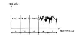
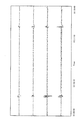
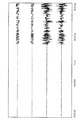
- FIG. 7 is a diagram showing a specific example of a sensor signal from the body motion sensor 31 which is a Doppler sensor.
- FIG. 7 represents a time change of the voltage value related to the amount of change in phase between the reflected wave from the body motion sensor 31 and the reflected wave from the surface of the measurement subject.
- the waveform represented by the sensor signal includes a waveform representing body movement (chest movement) accompanying breathing of the measurement subject (hereinafter also referred to as a breathing waveform) and body movement other than breathing such as turning over.
- a synthesized wave including a waveform hereinafter also referred to as a body motion waveform.
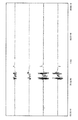
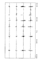
- FIG. 8 and 9 are diagrams showing specific examples of the respiratory waveform and the body movement waveform separated from the waveform shown in FIG.
- the human respiration waveform when in a stable sleep state has periodicity. Therefore, when the periodicity of the respiratory waveform is within a predetermined range, that is, when the variation in the cycle is within the predetermined range, it can be said that the sleep state is generally stable.
- the measurement subject is in a stable sleep state based on the periodicity of the respiratory waveform in that period and the magnitude of body movements other than respiration.
- the determination is made using both the respiratory waveform and the body movement waveform, but at least one of the waveforms may be used.
- the first determination unit 402 includes a determination unit 4021 and a correction unit 4022.
- the discriminating unit 4021 separates the waveform based on the input sensor signal shown in FIG. 7 into the respiratory waveform and the body motion waveform shown in FIG. 8 and FIG. And based on each waveform, it is discriminate
- the unit period here is, for example, about 30 seconds or 1 minute. That is, when the variation in the period of the respiratory waveform in the unit period t1 is smaller than a preset threshold value, it is determined that the respiratory waveform in the unit period t1 has periodicity. Further, it is determined whether the amplitude of the body movement waveform in the unit period t1 is larger or smaller than a preset threshold value.
- the determination unit 4021 determines the sleep state of the measurement subject in the unit period t1 as a sleep state ( S).
- the determination unit 4021 determines the sleep state of the measurement subject in the unit period t1 as an awake state ( W).
- the determination unit 4021 may determine the presence / absence of the measurement subject in the range in which the radio wave output from the body motion sensor 31 reaches.
- the determination unit 4021 determines that there is no subject to be measured in the above range. In other cases, it is determined that the person to be measured exists in the above range. Note that the determination unit 4021 determines the presence / absence state of the subject as state (E) when it is determined that the subject is present, and the state (N) when it is determined that the subject is not present. ).
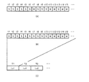
- FIG. 9A is a diagram illustrating a specific example of the determination result in the determination unit 4021. As shown in FIG. 9A, the determination unit 4021 determines whether the sleep state is a stable state or the awake state for each unit period of the waveform based on the input sensor signal.
- the correction unit 4022 corrects the determination result of the unit period according to the determination result of the adjacent unit periods.
- FIGS. 9A and 9B which shows a specific example of correction of the determination result shown in FIG. 9A in FIG.
- the continuous number of unit periods that are the same determination result is a predetermined number or less and the unit period that is the determination result opposite to the determination result is continuous a predetermined number or more before and after the continuous unit period
- the discrimination results of the continuous unit periods are corrected so as to be the opposite discrimination results.
- the determination unit 4021 determines the awake state (W) for the unit period t7 in FIG. 9A, but the unit period determined to be the awake state (W) is continuous with respect to the unit period t7. In other words, the unit period determined to be the sleep state (S) before and after the unit period t7 continues to some extent. A similar state in which the determination result is reversed is also observed for the unit period t13.
- the threshold value of the number of consecutive determination results of the target unit period is 2, and the threshold value of the number of continuous determination results of the unit periods before and after that (second threshold value).
- the continuous number 1 of the unit periods determined to be in the awake state (W) is smaller than the first threshold value, and the determination results before and after the unit period t7 are The condition that the number of consecutive unit periods 3 is larger than the second threshold value is satisfied.
- the correction unit 4022 corrects the determination result of the unit period of the unit period t7 so that the sleep state (S) which is the opposite determination result is obtained.
- the correction unit 4022 corrects the determination result of the unit period of the unit period t13 so as to be in the arousal state (W) that is the opposite determination result.
- the second discriminating unit 409 discriminates the sleep level based on the discriminating result of each unit period for a certain period in which the unit periods are continuous.
- the unit period here is, for example, about 5 minutes or 10 minutes.
- the level of sleep refers to the level of depth of sleep defined by the degree of respiratory stability, the presence or absence of body movement, and continuity.
- Level 1 Sleep state with no movement and stable breathing
- Level 2 Sleep state with single body movement
- Level 3 Sleep state with continuous body movement
- Level 4 Awakened state with continuous body movement
- Level 5 Full awake state
- Etc Etc.
- the second discriminating unit 409 stores, as the discriminating value for each level, the number of consecutive discriminating results for each unit period constituting a certain period and the ratio.
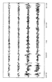
- FIG. 13 is a specific example of a waveform indicated by the symbolic sensor signal of level 1 above
- FIG. 14 is a specific example of a waveform indicated by the symbolic sensor signal of level 2 above
- FIG. 17 shows a specific example of the waveform indicated by the symbolic sensor signal of level 4 above
- FIG. 18 shows the waveform of the symbolic sensor signal indicated by level 5 above.
- the waveform shown by the sensor signal when entering the floor
- FIG. 19 is a diagram showing the waveform shown by the symbolic sensor signal of level 5 and especially the waveform shown by the sensor signal when leaving the floor.
- the second discriminating unit 409 stores in advance the discrimination number of each level and the ratio of the discrimination results represented by the waveforms indicated by these sensor signals.
- FIG. 9C is a diagram illustrating a specific example of the determination result of the sleep level for each certain period. That is, with reference to FIG. 9 (B) and FIG. 9 (C), the 2nd discrimination
- FIG. 10 is a block diagram illustrating a specific example of a functional configuration for detecting the occurrence of snoring in the evaluation apparatus 100.
- Each function shown in FIG. 10 is formed on the CPU 41 by the CPU 41 executing a program stored in the memory 42, but at least a part thereof is formed by a hardware configuration such as an electric circuit. May be.
- evaluation apparatus 100 includes awakening information acquisition unit 411 that acquires the level of sleep (level 1 to level 5) determined as described above for the measurement subject at that time, and microphone 32.
- a voice input unit 414 for receiving an input of a voice signal from the voice input unit, and measuring a frequency with respect to the voice signal input to the voice input unit 414 to obtain a predetermined amount or more in a frequency band which is a constituent element of the above snoring
- a voice discriminating unit 415 that discriminates that sound pressure has been detected, and a determining unit 418 that determines whether snore has occurred based on the discrimination result of the voice discriminating unit 415 and the information acquired by the awakening information acquiring unit 411.
- an output processing unit 419 for transmitting to the display unit 20 and / or the communication unit 50 in order to display the result determined by the determination unit 418.
- the result determined by the determination unit 418 can be displayed on another device by being transmitted to an external device via the communication unit 50.
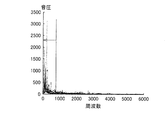
- FIG. 20 is a diagram showing the analysis result of a normal snoring sound.
- a normal snoring sound is generally composed of a sound of 1000 Hz or less.
- the determination unit 418 is based on the fact that a voice of 1000 Hz or less is detected with a sound pressure of a predetermined amount or more in the voice discrimination unit 415 during a period in which the level acquired by the awakening information acquisition unit 411 is level 1 to level 3. And determine that snoring has occurred.
- the CPU 41 determines the sleep level for a predetermined period. Then, the CPU 41 determines that the sleep level (sleep level 1 to level 3) is the accumulated time (sleep state time) when the sleep level (sleep level 1 to level 3) is determined for the first time from the first level to the level 3 level. ) And, if snoring occurs during the period, that effect is displayed on the display unit 20.
- the predetermined period may be a period (a period from a measurement start time to a measurement end time, which will be described later) stored in advance in the memory 42, or is determined by an operation on the button group 10 by the measurement subject. It may be a period.
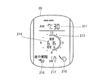
- FIG. 11 is a diagram illustrating an example of a display mode of the display unit 20.
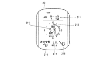
- display unit 20 includes a display field 211 that displays the current time, a display field 214 that displays the sleep state time, and a display field 218 that displays an image indicating that snoring has occurred. .
- the period from the time when the sleep level is first determined to be one of level 1 to level 3 to the time when it is determined to be a wake-up state (described later) in the predetermined period is referred to as sleep time.
- the sleep time includes a time in the sleep state and a time in the awake state.
- the sleep state time described above is the cumulative time of the sleep state of the sleep time.
- the cumulative time of the awake state in the sleep time is referred to as the awake state time.
- the display column 213 for distinguishing and displaying the sleep state in the sleep time and the awake state the display column 216 for displaying an image indicating that the awake state has occurred during the sleep time, It includes a display field 217 that indicates the time (wake state time) when the wake state occurs during the sleep time.
- the CPU 41 displays on the display unit 20 that the detection output of the body motion sensor 31 for determining the sleep level is acquired during the predetermined time.
- FIG. 12 is a diagram showing an example of such a display mode.
- determines the level of a sleep state for every unit period as mentioned above based on the detection output of the body motion sensor 31.
- FIG. In the display example illustrated in FIG. 12, immediately after the CPU 41 acquires the detection output of the body motion sensor 31, the level of the sleep state is determined for each unit period for the detection output.
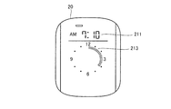
- the display part 20 contains the display column 212 which displays the discrimination
- the CPU 41 determines the level of the sleep state described above, such as determining the level of the sleep state for each unit period in response to an operation on the button group 10. This determination may not be performed immediately after the detection output is acquired. In such a case, the display of the display column 212 on the display unit 20 during the sleeping time may be omitted.
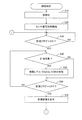
- FIG. 21 is a flowchart of processing (sleep discrimination processing) for discriminating the sleep state of the measurement subject in the evaluation apparatus 100. This process is started, for example, when the evaluation apparatus 100 is turned on. Note that the operation in this process is realized by the CPU 41 reading and executing a display program stored in the memory 42 and exhibiting the functions shown in FIG.
- the CPU 41 sets ON / OFF of the measurement flag.
- the state of the measurement flag is set to OFF. The function of the flag will be described later.
- the CPU 41 initializes the evaluation apparatus 100 in step S10, and advances the process to step S20.
- step S20 the CPU 41 starts obtaining a sensor signal using the body motion sensor 31, and advances the process to step S30.
- step S30 the CPU 41 determines whether or not the state of the measurement flag is ON. If it is determined that the measurement flag is ON, the process proceeds to step S40. On the other hand, if it is OFF, it waits in step S30 until it is turned ON. Note that the CPU 41 determines the state of the measurement flag on the condition that the button group 10 (a specific button included in the button group 10) is operated or the measurement start time stored in advance in the memory 42 has arrived. Change to ON.
- step S ⁇ b> 40 the CPU 41 determines whether or not the measurement target exists within the detection range of the body motion sensor 31, that is, whether or not the subject is within the range where the radio wave output from the body motion sensor 31 reaches. To do. For example, as described above, after the waveform of the signal output from the body motion sensor 31 is separated into a respiratory waveform and a body motion waveform as described above, the amplitude of the waveform is determined in either the respiratory waveform or the body motion waveform. This is realized based on whether or not a state smaller than a specific value has continued for a specific time (for example, 30 seconds).
- a specific time for example, 30 seconds
- step S50 When it is determined that there is a person to be measured, that is, when it is determined as the state (E), the CPU 41 advances the process to step S50. If it is determined that there is no person to be measured, that is, if it is determined that the state is (N), the process proceeds to step S60 without performing the process of step S50.
- step S50 CPU41 discriminate
- the CPU 41 sets the periodicity of the respiratory waveform for each preset unit period and / or the amplitude of the body motion waveform. Based on the size, the sleep state in that period is determined for each unit period. Further, the determination result is corrected according to the determination result of the adjacent unit periods. Further, the sleep level is determined based on the determination result of each unit period for a certain period in which the unit periods are continuous. Then, the obtained sleep level is stored in the memory 42 together with time information corresponding to the sleep level.
- step S60 the CPU 41 determines whether or not the state of the measurement flag is OFF. If it is determined that the measurement flag is OFF, the process proceeds to step S70. On the other hand, if it is determined to be ON, the process returns to step S40.
- the CPU 41 turns the measurement flag state OFF by operating the button group 10 (a specific button included in the button group 10) when the measurement flag state is ON. Further, the CPU 41 may turn off the state of the measurement flag based on the detection output of the body motion sensor 31. For example, when the state determined to be the state (N) in step S40 continues for a predetermined time, the CPU 41 may turn off the state of the measurement flag. The CPU 41 determining that the state of the measurement flag has been turned off corresponds to determining that the measurement subject is in the wake-up state.
- step S70 the CPU 41 displays the determination result of the sleep level and the like during the period from the determination of the measurement flag state in step S30 to the determination in step S60 that the measurement flag state is OFF. Then, the process returns to step S40.
- the sleep level is discriminated during the period when the state of the measurement flag is ON. This period corresponds to the predetermined period described above.
- the measurement result is displayed on the display unit 20 in response to the determination that the state of the measurement flag has returned to OFF (YES in step S60).
- the measurement result may not necessarily be displayed at this timing, and may be performed at a timing such as when the button group 10 is further operated after the measurement flag is turned off.
- the display of the measurement result may be performed on the display unit 20, or may be performed on another device such as the display device 200 that acquires necessary data from the CPU 41.
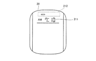
- step S30 If it is determined in step S30 that the state of the measurement flag is ON, the time at that time is displayed on the display section 211 on the display unit 20, as shown in FIG. Note that the CPU 41 may increase the brightness of the entire surface of the display unit 20 for a few seconds immediately after it is determined that the state of the measurement flag is ON in order to notify that the determination of the sleep level is started.
- step S60 the state of the measurement flag is OFF.
- the display in the display column 212 is appropriately updated according to the change in the sleep state level determination result.
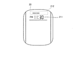
- step S60 If it is determined in step S60 that the state of the measurement flag is OFF, the CPU 41 displays the current time in the display field 211 and the current time in the display field 212 on the display unit 20, as shown in FIG.
- the display brightness of the entire display unit 20 is temporarily improved (for example, for a few seconds) in a state where the result of determining the sleep state level is displayed.
- FIGS. 25 and 26 Display of sleep time
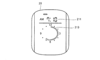
- the display column 213 is a column for displaying a plurality of bars arranged in a circle.
- the plurality of bars arranged at 360 degrees are arranged to correspond to 12 hours. Five bars correspond to one hour. That is, one bar corresponds to 12 minutes. Therefore, a maximum of 62 bars can be displayed in the display field 213.
- the display of the information showing the sleep time in the display column 213 displays the bar of the position and number corresponding to sleep time in the several bar arranged circularly (at 360 degree
- a plurality of display portions arranged in a circle are configured by such a plurality of bars.
- FIG. 26 shows a display example of the display unit 20 in this case.
- a bar corresponding to 12:10 pm to a bar corresponding to 7:10 am the next morning is displayed.
- the bars shown in FIG. 25 may be displayed in order, that is, the displayed bars may be sequentially displayed in the clockwise direction.
- the length of the sleep time can be emphasized and displayed for a person who sees the display of the sleep time on the display unit 20 such as the person being measured. Therefore, the person to be measured can have a strong impression of the length of the sleep time, and the degree of satisfaction with the sleep can be improved.
- the sleeping time is displayed by displaying / hiding a plurality of bars, and the plurality of bars are arranged in a circle to represent a clock.
- FIG. 27 Display of sleep state time, etc.
- the CPU 41 causes the display unit 20 to display the sleep state time, the wake-up state time, and the snoring during the sleep time.
- FIG. 27 is a diagram illustrating an example of display contents on the display unit 20 at this time.
- sleep state time is displayed in display column 214
- awake state time is displayed in display column 217
- an image indicating that snoring has occurred is displayed in display column 218.
- the state of the measurement flag is turned on at 10:30 pm
- the level of the subject's sleep is the level corresponding to the sleep state (level 1 to level 3) for the first time at 12:10 am on the next day. )
- the state of the measurement flag is turned off at 7:10 am
- the arousal state time from 12:10 am to 7:10 am is 1 hour 25 minutes
- the measurement result is shown.
- the sleep state time is 5 hours and 35 minutes obtained by subtracting the awake state time (1 hour and 25 minutes) from the sleep time (7 hours).
- FIG. 28 shows a state in which, among the bars corresponding to the sleep time displayed in FIG. 27, the bar corresponding to the awake state time is temporarily not displayed due to blinking.
- the bar corresponding to the awakening state time at is blinked.
- This blinking display may be stopped by an external operation such as an operation on the button group 10, or may be stopped after a certain period of time.
- buttons 20 display units, 30 sensors, 31 body motion sensors, 32 microphones, 40 control units, 41 CPUs, 42 memories, 50 communication units, 100 evaluation units, 200 display units, 401 input units, 402 first discrimination units, 403 determination unit, 404 generation unit, 405 storage unit, 406 readout unit, 407 display control unit, 408 communication control unit, 409 second determination unit, 410 input information processing unit, 411 awakening information acquisition unit, 414 voice input unit, 415 Voice discrimination unit, 4021 discrimination unit, 4022 correction unit.
Landscapes
- Health & Medical Sciences (AREA)
- Life Sciences & Earth Sciences (AREA)
- Molecular Biology (AREA)
- Surgery (AREA)
- Biophysics (AREA)
- Pathology (AREA)
- Engineering & Computer Science (AREA)
- Biomedical Technology (AREA)
- Heart & Thoracic Surgery (AREA)
- Medical Informatics (AREA)
- Veterinary Medicine (AREA)
- Physics & Mathematics (AREA)
- Animal Behavior & Ethology (AREA)
- General Health & Medical Sciences (AREA)
- Public Health (AREA)
- Anesthesiology (AREA)
- Measurement Of The Respiration, Hearing Ability, Form, And Blood Characteristics Of Living Organisms (AREA)
- Physiology (AREA)
- Dentistry (AREA)
- Oral & Maxillofacial Surgery (AREA)
- Pulmonology (AREA)
Abstract
Description
たとえば、特許文献1(特開2007-319238号公報)には、睡眠の深さの時間変化を計測し、当該計測結果をグラフ表示する技術が開示されている。また、特許文献2(特開2009-22671号公報)では、12時間分の血圧等の生体情報の計測結果をレーダーチャートの形式で表示する技術が開示されている。
図1は、本実施の形態にかかる睡眠レベル評価装置(以下、評価装置と略する)100の外観の具体例を示す図である。また、図2は評価装置100の側面を表わした概略図であり、図3は、斜め上方から見た外観の概略図である。
図4は、評価装置100のハードウェア構成の具体例を示すブロック図である。
図5は、評価装置100の使用例を説明する図である。
図6は、評価装置100において、睡眠状態であるか覚醒状態であるかの判別の一例である、睡眠のレベルの判別のための機能構成の具体例を示すブロック図である。図6に表わされる各機能は、主に、CPU41がメモリ42に記憶されるプログラムを実行することによってCPU41上に形成されるものであるが、少なくとも一部が電気回路などのハードウェア構成によって形成されてもよい。
ここで、第2判別部409での睡眠のレベルの判別方法について説明する。
レベル1:体動がなく、呼吸が安定している睡眠状態、
レベル2:単発的な体動がある睡眠状態、
レベル3:連続的な体動がある睡眠状態、
レベル4:連続的な体動が続く覚醒状態、
レベル5:完全な覚醒状態、
などが挙げられる。
図10は、評価装置100においていびきの発生を検出するための機能構成の具体例を示すブロック図である。図10に表わされる各機能は、主に、CPU41がメモリ42に記憶されるプログラムを実行することによってCPU41上に形成されるものであるが、少なくとも一部が電気回路などのハードウェア構成によって形成されてもよい。
評価装置100では、CPU41は、所定期間、睡眠のレベルの判別を行なう。そして、CPU41は、当該所定期間のうち睡眠のレベルが初めてレベル1~レベル3のいずれかと判別したときから睡眠状態(睡眠のレベル1~レベル3)と判別された期間の累積時間(睡眠状態時間)と、当該期間においていびきが発生した場合にはその旨とを、表示部20に表示する。ここで、所定期間とは、予めメモリ42に記憶された期間(後述する測定開始時刻から測定終了時刻までの期間)であっても良いし、被測定者によるボタン群10に対する操作等によって定められる期間であっても良い。
図11を参照して、表示部20は、現在時刻を表示する表示欄211と、睡眠状態時間を表示する表示欄214と、いびきが発生したことを示す画像を表示する表示欄218とを含む。
<測定中表示の例>
評価装置100では、CPU41は、上記所定時間中、表示部20に、睡眠のレベルを判別するための体動センサ31の検出出力を取得している旨を表示する。
図12を参照して、CPU41は、体動センサ31の検出出力に基づいて、上記したように単位期間ごとに睡眠状態のレベルを判別する。図12に示された表示例は、CPU41が、体動センサ31の検出出力を取得した直後に、当該検出出力について単位期間ごとに睡眠状態のレベルを判別する。そして、表示部20は、当該睡眠状態のレベルの判別結果を表示する表示欄212を含む。表示欄212では、複数のバーが表示可能である。CPU41は、単位期間ごとに睡眠状態のレベルを判別し、判別したレベルに応じた数のバーを、表示欄212に表示させる。
図21は、評価装置100における、被測定者の睡眠状態を判別するための処理(睡眠判別処理)のフローチャートである。当該処理は、たとえば、評価装置100における電源投入時に開始される。なお、当該処理における動作は、CPU41がメモリ42に記憶される表示用のプログラムを読み出して実行し、図6に示された各機能を発揮することによって実現される。
図21を参照して説明した睡眠判別処理における、表示部20における表示内容の変化の一例を説明する。
ステップS30において計測フラグの状態がONであると判断されると、表示部20には、図22に示されるように、表示欄211にその時点の時刻が表示される。なお、計測フラグの状態がONであると判断された直後数秒間、CPU41は、睡眠のレベルの判別が開始されることを報知すべく、表示部20の全面の輝度を上げても良い。
その後、ステップS40に処理が進められると、表示部20には、図23に示されるように、表示欄211にその時点の時刻が表示され、さらに、表示欄212にその時点での睡眠状態のレベルの判別結果が表示される。
ステップS60で、計測フラグの状態がOFFであると判断すると、CPU41は、図24に示されるように、表示部20において、表示欄211にその時点の時刻を表示し、表示欄212にその時点での睡眠状態のレベルの判別結果を表示した状態で、表示部20全体の表示の輝度を一時的に(たとえば、数秒間)向上させる。
その後、表示欄213に、上記睡眠時間を表す情報を表示させる。
図26の表示欄213では、午後12時10分に対応するバーから、翌朝の午前7時10分に対応するバーまでが、表示されている。
上記した睡眠時間の表示が終了すると、CPU41は、表示部20に、さらに、上記した睡眠状態時間、覚醒状態時間、および、睡眠時間中のいびきがあった場合にはその旨を表示させる。図27は、このときの表示部20における表示内容の一例を示す図である。
CPU41は、表示部20において、図27に示すような睡眠状態時間等を表示した後、さらに、表示欄213に表示させた、睡眠時間に対応するバーのうち、覚醒状態時間に対応するバーを点滅表示させても良い。図28に、図27において表示されていた、睡眠時間に対応するバーのうち、覚醒状態時間に対応するバーが点滅によって一時的に表示されなくなる状態を示す。
Claims (11)
- 寝床上の被測定者の身体の動きを検出するための体動検出手段(30)と、
前記体動検出手段の検出結果に基づいて、第1の期間における被測定者の睡眠状態を判別するための第1の判別手段(402)と、
前記第1の判別手段による判別結果に基づいて、前記第1の期間より長い第2の期間ごとに睡眠状態であるか覚醒状態であるかを判別するための第2の判別手段(409)と、
前記第2の判別手段による判別結果を表示装置(20)に表示させるための表示手段(407)とを備え、
前記表示手段は、前記第2の判別手段による判別結果に基づいて、前記睡眠状態における途中覚醒の発生に関する情報を前記表示装置にさらに表示させる、睡眠評価装置。 - 前記途中覚醒の発生に関する情報は、少なくとも前記睡眠状態における途中覚醒の発生の時間または回数である、請求項1に記載の睡眠評価装置。
- 前記表示手段は、
前記表示装置において円状に配列された複数の表示部を表示させ、
前記第2の判別手段による判別結果を、各前記表示部を一定の期間に対応させながら、前記複数の表示部を用いて表示させる、請求項1または請求項2に記載の睡眠評価装置。 - 前記表示手段は、前記睡眠状態と前記覚醒状態のうち、いずれか一方の状態に判別された期間に対応する前記表示部と、他方の状態に判別された期間に対応する前記表示部とを、互いに異なる表示態様で表示させる、請求項3に記載の睡眠評価装置。
- 前記表示手段は、前記睡眠状態と前記覚醒状態のうち、いずれか一方の状態に判別された期間に対応する前記表示部を点灯表示させ、他方の状態に判別された期間に対応する前記表示部を点滅表示させる、請求項4に記載の睡眠評価装置。
- 前記第1の判別手段は、前記第1および前記第2の期間より長い特定の期間について、前記第1の期間ごとに被測定者の睡眠状態を判別し、
前記表示手段は、前記特定の期間における、前記第2の判別手段による判別結果での前記睡眠状態または前記覚醒状態のいずれかの累積時間を、前記表示装置にさらに表示させる、請求項1に記載の睡眠評価装置。 - 前記第2の判別手段は、前記第1の判別手段による判別結果に基づいて被測定者の起床状態をさらに判別し、
前記表示手段は、前記第2の判別手段が被測定者の前記起床状態を判別したことに応じて、前記表示装置に前記睡眠状態における途中覚醒の発生に関する情報を表示させる、請求項6に記載の睡眠評価装置。 - 前記特定の期間の終了を指定する情報の入力を受け付ける入力手段(10)をさらに備え、
前記表示手段は、前記入力手段に対する入力がなされたことに応じて、前記表示装置に前記睡眠状態における途中覚醒の発生に関する情報を表示させる、請求項6に記載の睡眠評価装置。 - 被測定者のいびきの発生を検出する検出手段(32)をさらに備え、
前記表示手段は、前記表示装置において、さらに、前記検出手段が被測定者のいびきを検出した場合には、いびきの発生が検出されたことを示す情報を表示させる、請求項1に記載の睡眠評価装置。 - 前記表示手段は、前記表示装置に、さらに、前記第1の判別手段による判別結果を表示させる、請求項1に記載の睡眠評価装置。
- 寝床上の被測定者の身体の動きを検出するための体動検出手段を備えた睡眠評価装置において実行される睡眠評価方法であって、
前記体動検出手段の検出結果に基づいて、第1の期間における被測定者の睡眠状態を判別するステップ(S50)と、
前記第1の期間における前記判別の結果に基づいて、前記第1の期間より長い第2の期間ごとに睡眠状態であるか覚醒状態であるかを判別するステップ(S50)と、
前記第2の期間における前記判別の結果を表示装置に表示させるステップ(S70)と、
前記第2の期間における前記判別の結果に基づいて、前記睡眠状態における途中覚醒の発生に関する情報を前記表示装置に表示させるステップ(S70)とを備える、睡眠評価方法。
Priority Applications (3)
| Application Number | Priority Date | Filing Date | Title |
|---|---|---|---|
| US13/982,453 US20130310662A1 (en) | 2011-03-11 | 2011-12-20 | Sleep evaluation device and sleep evaluation method |
| CN201180069082.XA CN103415248B (zh) | 2011-03-11 | 2011-12-20 | 睡眠评价装置和睡眠评价方法 |
| DE112011105022T DE112011105022T5 (de) | 2011-03-11 | 2011-12-20 | Schlafauswertungsvorrichtung und Schlafauswertungsverfahren |
Applications Claiming Priority (2)
| Application Number | Priority Date | Filing Date | Title |
|---|---|---|---|
| JP2011-054173 | 2011-03-11 | ||
| JP2011054173A JP5724479B2 (ja) | 2011-03-11 | 2011-03-11 | 睡眠評価装置および睡眠評価方法 |
Publications (1)
| Publication Number | Publication Date |
|---|---|
| WO2012124234A1 true WO2012124234A1 (ja) | 2012-09-20 |
Family
ID=46830333
Family Applications (1)
| Application Number | Title | Priority Date | Filing Date |
|---|---|---|---|
| PCT/JP2011/079518 WO2012124234A1 (ja) | 2011-03-11 | 2011-12-20 | 睡眠評価装置および睡眠評価方法 |
Country Status (5)
| Country | Link |
|---|---|
| US (1) | US20130310662A1 (ja) |
| JP (1) | JP5724479B2 (ja) |
| CN (1) | CN103415248B (ja) |
| DE (1) | DE112011105022T5 (ja) |
| WO (1) | WO2012124234A1 (ja) |
Families Citing this family (26)
| Publication number | Priority date | Publication date | Assignee | Title |
|---|---|---|---|---|
| JP5870706B2 (ja) * | 2012-01-20 | 2016-03-01 | オムロンヘルスケア株式会社 | 睡眠表示プログラム、睡眠表示方法及び睡眠表示装置 |
| GB201310824D0 (en) * | 2013-06-18 | 2013-07-31 | Smiths Medical Int Ltd | Respiratory therapy apparatus and methods |
| WO2015006364A2 (en) | 2013-07-08 | 2015-01-15 | Resmed Sensor Technologies Limited | Method and system for sleep management |
| US11648373B2 (en) | 2013-07-08 | 2023-05-16 | Resmed Sensor Technologies Limited | Methods and systems for sleep management |
| USD765256S1 (en) | 2014-05-09 | 2016-08-30 | Resmed Sensor Technologies Limited | Apparatus for sleep information detection |
| JP6288755B2 (ja) * | 2013-07-12 | 2018-03-07 | 株式会社タニタ | 監視システム、及び、活動量計 |
| RU2016129163A (ru) * | 2013-12-19 | 2018-01-24 | Конинклейке Филипс Н.В. | Устройство для наблюдения за ребенком |
| CN103815878B (zh) * | 2014-02-21 | 2016-01-13 | 深圳清华大学研究院 | 基础体温检测装置以及基础体温的检测方法 |
| FR3023913B1 (fr) * | 2014-07-16 | 2017-10-20 | Legrand France | Dispositif de detection de rayonnement infrarouge et procede de determination d'une indication de presence ou de mouvement |
| USD748271S1 (en) * | 2014-08-22 | 2016-01-26 | Resmed Sensor Technologies Limited | Monitoring device |
| JP6337972B2 (ja) * | 2014-10-31 | 2018-06-06 | 富士通株式会社 | 状態表示方法、プログラム及び状態表示装置 |
| WO2016067449A1 (ja) | 2014-10-31 | 2016-05-06 | 富士通株式会社 | 状態表示方法、プログラム及び状態表示装置 |
| JP6485037B2 (ja) | 2014-12-25 | 2019-03-20 | オムロン株式会社 | 睡眠改善システム及びこのシステムを用いた睡眠改善方法 |
| KR102423752B1 (ko) * | 2015-01-28 | 2022-07-22 | 삼성전자주식회사 | 수면 중인 대상체의 쾌면을 유도하는 방법 및 이를 위한 쾌면 유도 장치 |
| CN104800061A (zh) * | 2015-04-30 | 2015-07-29 | 深圳市前海安测信息技术有限公司 | 用于睡眠质量管理的按摩枕及其控制方法 |
| WO2016179651A1 (en) | 2015-05-13 | 2016-11-17 | Resmed Limited | Systems and methods for screening, diagnosis, and monitoring of sleep-disordered breathing |
| CN106419865A (zh) * | 2015-08-07 | 2017-02-22 | 上海宽带技术及应用工程研究中心 | 基于振动传感器的睡眠呼吸暂停综合症的判断方法 |
| USD774197S1 (en) * | 2015-10-07 | 2016-12-13 | Hello Inc. | Sleep monitoring device |
| CN105231997A (zh) * | 2015-10-10 | 2016-01-13 | 沈阳熙康阿尔卑斯科技有限公司 | 一种睡眠质量判定方法及睡眠仪 |
| CN106108843A (zh) * | 2016-06-17 | 2016-11-16 | 美的集团股份有限公司 | 一种确定用户睡眠时长的方法及系统 |
| WO2018097187A1 (ja) * | 2016-11-22 | 2018-05-31 | パラマウントベッド株式会社 | 端末装置、出力方法及びコンピュータプログラム |
| KR101883226B1 (ko) * | 2016-12-30 | 2018-07-30 | (주)더블유알티랩 | 레이더를 이용하여 수면 효율을 측정하는 방법 및 장치 |
| USD861176S1 (en) * | 2017-09-29 | 2019-09-24 | Lg Electronics Inc. | Sleep tracker |
| JP7222509B2 (ja) * | 2018-05-24 | 2023-02-15 | 株式会社oneA | 睡眠状態測定装置 |
| CN108985180A (zh) * | 2018-06-22 | 2018-12-11 | 张小勇 | 数据处理方法和系统 |
| CN109445268A (zh) * | 2018-12-29 | 2019-03-08 | 华勤通讯技术有限公司 | 一种闹铃控制方法、终端设备及存储介质 |
Citations (2)
| Publication number | Priority date | Publication date | Assignee | Title |
|---|---|---|---|---|
| JP2007195823A (ja) * | 2006-01-27 | 2007-08-09 | Daikin Ind Ltd | 睡眠情報提供システム |
| JP2009072214A (ja) * | 2007-09-18 | 2009-04-09 | Panasonic Electric Works Co Ltd | いびき検出装置 |
Family Cites Families (9)
| Publication number | Priority date | Publication date | Assignee | Title |
|---|---|---|---|---|
| JP2002116271A (ja) * | 2000-10-11 | 2002-04-19 | Yumex Co Ltd | 目覚し時計表示装置 |
| CN101227858B (zh) * | 2005-07-26 | 2010-06-23 | 松下电工株式会社 | 照明系统 |
| JP4367390B2 (ja) * | 2005-08-30 | 2009-11-18 | ダイキン工業株式会社 | 睡眠管理システム |
| US8532737B2 (en) * | 2005-12-29 | 2013-09-10 | Miguel Angel Cervantes | Real-time video based automated mobile sleep monitoring using state inference |
| WO2007107900A2 (en) * | 2006-03-21 | 2007-09-27 | Koninklijke Philips Electronics N.V. | Indication of the condition of a user |
| JP4825586B2 (ja) | 2006-05-30 | 2011-11-30 | 東芝コンシューマエレクトロニクス・ホールディングス株式会社 | 睡眠モニタ装置 |
| JP5297008B2 (ja) | 2007-07-23 | 2013-09-25 | フクダ電子株式会社 | 生体情報処理装置及び生体情報処理方法 |
| JP2009225971A (ja) * | 2008-03-21 | 2009-10-08 | Toshiba Corp | 睡眠状態計測装置及び方法 |
| US20130289419A1 (en) * | 2011-01-14 | 2013-10-31 | Koninklijke Philips N.V. | Activity visualization device |
-
2011
- 2011-03-11 JP JP2011054173A patent/JP5724479B2/ja active Active
- 2011-12-20 DE DE112011105022T patent/DE112011105022T5/de active Pending
- 2011-12-20 CN CN201180069082.XA patent/CN103415248B/zh active Active
- 2011-12-20 US US13/982,453 patent/US20130310662A1/en not_active Abandoned
- 2011-12-20 WO PCT/JP2011/079518 patent/WO2012124234A1/ja active Application Filing
Patent Citations (2)
| Publication number | Priority date | Publication date | Assignee | Title |
|---|---|---|---|---|
| JP2007195823A (ja) * | 2006-01-27 | 2007-08-09 | Daikin Ind Ltd | 睡眠情報提供システム |
| JP2009072214A (ja) * | 2007-09-18 | 2009-04-09 | Panasonic Electric Works Co Ltd | いびき検出装置 |
Also Published As
| Publication number | Publication date |
|---|---|
| JP2012187299A (ja) | 2012-10-04 |
| US20130310662A1 (en) | 2013-11-21 |
| DE112011105022T5 (de) | 2013-12-19 |
| CN103415248A (zh) | 2013-11-27 |
| CN103415248B (zh) | 2016-01-20 |
| JP5724479B2 (ja) | 2015-05-27 |
Similar Documents
| Publication | Publication Date | Title |
|---|---|---|
| JP5724479B2 (ja) | 睡眠評価装置および睡眠評価方法 | |
| US8933809B2 (en) | Sleep evaluation device and display method for sleep evaluation device | |
| JP5788293B2 (ja) | 睡眠評価装置および睡眠評価用プログラム | |
| JP5788251B2 (ja) | 睡眠時情報検出装置および睡眠時情報検出装置における検出方法 | |
| JP5853635B2 (ja) | 睡眠評価装置 | |
| US20130281874A1 (en) | Recording medium, apnea determining device, and apnea determining method | |
| WO2012124235A1 (ja) | 睡眠評価装置および睡眠評価方法 | |
| JP7073914B2 (ja) | 喘鳴検出装置及び喘鳴検出プログラム | |
| JP5749121B2 (ja) | 睡眠状態評価装置、睡眠状態評価システム及びプログラム | |
| JP2019098068A (ja) | 睡眠状態判定装置及びプログラム | |
| JP4063618B2 (ja) | 睡眠モニタリングシステム及びモニタリング装置 | |
| JP6518056B2 (ja) | 睡眠状態判定装置、睡眠状態判定方法及びプログラム | |
| JP2014039586A (ja) | 睡眠改善支援装置 | |
| JP2008206596A (ja) | 睡眠状態判別装置 | |
| JP2009045227A (ja) | 目覚まし装置 | |
| JP6186896B2 (ja) | 睡眠判定装置と睡眠判定方法 | |
| JP2016187429A (ja) | 就寝案内装置 | |
| WO2017221937A1 (ja) | 生体情報測定支援装置、生体情報測定装置、生体情報測定支援方法、及び、生体情報測定支援プログラム | |
| CA3100475C (en) | Apparatus and a method for monitoring a patient during his sleep | |
| JP2001231864A (ja) | 快適目覚まし装置 | |
| JP7143784B2 (ja) | 介護支援装置、介護支援方法、および介護支援システム | |
| JP6385751B2 (ja) | 睡眠障害判定装置、睡眠障害判定方法及びプログラム | |
| KR101748672B1 (ko) | 음성통신 및 유선통신을 이용하는 전자파 프리 기반 신체 및 거동정보 수집제공 시스템 | |
| JP6976387B2 (ja) | 評価装置及びプログラム |
Legal Events
| Date | Code | Title | Description |
|---|---|---|---|
| 121 | Ep: the epo has been informed by wipo that ep was designated in this application |
Ref document number: 11861068 Country of ref document: EP Kind code of ref document: A1 |
|
| DPE1 | Request for preliminary examination filed after expiration of 19th month from priority date (pct application filed from 20040101) | ||
| WWE | Wipo information: entry into national phase |
Ref document number: 13982453 Country of ref document: US |
|
| WWE | Wipo information: entry into national phase |
Ref document number: 112011105022 Country of ref document: DE Ref document number: 1120111050224 Country of ref document: DE |
|
| 122 | Ep: pct application non-entry in european phase |
Ref document number: 11861068 Country of ref document: EP Kind code of ref document: A1 |