WO2012124083A1 - スライドファスナー用スライダー - Google Patents
スライドファスナー用スライダー Download PDFInfo
- Publication number
- WO2012124083A1 WO2012124083A1 PCT/JP2011/056284 JP2011056284W WO2012124083A1 WO 2012124083 A1 WO2012124083 A1 WO 2012124083A1 JP 2011056284 W JP2011056284 W JP 2011056284W WO 2012124083 A1 WO2012124083 A1 WO 2012124083A1
- Authority
- WO
- WIPO (PCT)
- Prior art keywords
- lock member
- slider
- slide fastener
- base
- pin
- Prior art date
- Legal status (The legal status is an assumption and is not a legal conclusion. Google has not performed a legal analysis and makes no representation as to the accuracy of the status listed.)
- Ceased
Links
Images





Classifications
-
- A—HUMAN NECESSITIES
- A44—HABERDASHERY; JEWELLERY
- A44B—BUTTONS, PINS, BUCKLES, SLIDE FASTENERS, OR THE LIKE
- A44B19/00—Slide fasteners
- A44B19/24—Details
- A44B19/26—Sliders
- A44B19/265—Sliders with means for preventing the accidental intrusion of material into the slider body, e.g. with shield or guard
-
- A—HUMAN NECESSITIES
- A44—HABERDASHERY; JEWELLERY
- A44B—BUTTONS, PINS, BUCKLES, SLIDE FASTENERS, OR THE LIKE
- A44B19/00—Slide fasteners
- A44B19/24—Details
- A44B19/26—Sliders
- A44B19/30—Sliders with means for locking in position
- A44B19/308—Sliders with means for locking in position in the form of a spring-actuated locking member actuated by the pull member
Definitions
- the present invention relates to a slide fastener slider, and more particularly to a slide fastener slider capable of retrofitting a handle to a trunk.
- a cover member having a downwardly concave shape is arranged from the guide pillar of the upper blade toward the rear opening, and the lock member rotates up and down at a position near the guide pillar in the cover member.
- the lock member has a claw that protrudes from the claw hole established in the upper wing plate to the position of the fastener element row, and an operating recess that opens toward the rear opening and accommodates the handle shaft
- the lock member is urged so that the claw portion is always protruded from the claw hole, and the gap between the end portion on the rear opening side of the cover member and the upper blade is the insertion gap of the shaft portion of the handle.
- an opening / closing member that opens and closes the gap (see, for example, Patent Document 1).
- the present invention has been made in view of the above-described circumstances, and an object thereof is to provide a slider for a slide fastener that can prevent clogging of a lock member in a supply chute even when the slider is downsized. It is in.
- the above object of the present invention can be achieved by the following constitution.
- a base portion having a pin insertion hole, and an upper piece portion and a lower piece portion that extend respectively rearward from the base portion and are opposed to each other in the vertical direction.
- a slider for a slide fastener in which a claw portion that enters the element guide path is formed, and the lower piece portion is bent with respect to the base portion so as to be offset to one side in the width direction of the lock member, and the pin insertion hole of the base portion is formed.
- the front and upper part has a lock Slide fastener slider, wherein a stepped portion is formed having an end surface extending in a direction crossing the longitudinal direction of the wood.
- a spring for urging the lock member is provided so that the claw portion enters the element guide path, and the front and lower portions of the pin insertion hole of the base portion are recessed stepwise above the lock member, and the spring urging force
- the lower piece portion of the lock member is bent with respect to the base portion so as to be offset to one side in the width direction of the lock member, and in front of the pin insertion hole of the base portion of the lock member and
- the upper portion is formed with a step portion having an end surface extending in a direction intersecting with the front-rear direction of the lock member. Therefore, when a plurality of lock members are loaded on the supply chute, the upper piece of the rear lock member is The leading end abuts against the end surface of the stepped portion of the leading locking member, and the leading end portion of the lower piece of the trailing locking member overlaps the base of the leading locking member in the width direction.
- the rear locking member presses the leading locking member in a direction parallel to the moving direction, so that the posture of the locking member in the supply chute is stabilized and the locking member can be prevented from being clogged.
- the “leading lock member” is a lock member that moves first in the supply chute
- the “rear lock member” means a lock member that moves later in the supply chute. is there.
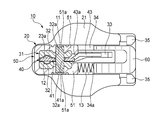
- FIG. 4 is a sectional view taken along line AA in FIG. 3.
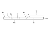
- FIG. 4 is a side view of the lock member shown in FIG. 3.
- FIG. 4 is a top view of the lock member shown in FIG. 3. It is a longitudinal cross-sectional view of the slider explaining the state by which the shaft part of the handle was pushed into the insertion gap.
- the upper side is the upper side with respect to the paper surface of FIG. 3
- the lower side is the lower side with respect to the paper surface of FIG. 3
- the front side is the left side with respect to the paper surface of FIG. 3 is the right side
- the right side is the back side of the paper surface of FIG. 3
- the left side is the front side of the paper surface of FIG.
- the left-right direction of the slider is also called the width direction.
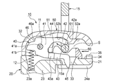
- the slide fastener slider 10 of the present embodiment is a slider with a function of automatically stopping the pulling after attachment, and includes a body 20 as shown in FIGS. 1 to 3, and the body 20 is separated in the vertical direction.
- the upper wing plate 21 and the lower wing plate 22 that are arranged in parallel, the guide column 23 that connects the upper wing plate 21 and the lower wing plate 22 at the front end, and the lower side along the left and right side edges of the upper wing plate 21
- left and right shoulders 25 separated by the guide pillars 23 are formed at the front of the body 20, and a rear opening 26 is formed at the rear of the body 20.
- a substantially Y-shaped element guide path 27 that connects the left and right shoulder openings 25 and the rear opening 26 is formed between the upper wing board 21 and the lower wing board 22.
- a passage through which the illustrated fastener element row is inserted is formed.
- the slide fastener slider 10 includes a lock member 40 that is supported by a column portion 31 erected on the front end portion of the upper surface of the upper blade 21 so as to be able to swing up and down, and the column portion 31 and the lock member 40 are moved upward.
- the cover member 50 covering from the top, the pillar portion 31, the lock member 40, and the pin 11 that is the rotation center of the lock member 40, and between the rear end portion of the cover member 50 and the upper blade plate 21.
- an opening / closing member 60 that opens and closes a gap S (hereinafter referred to as “insertion gap S”) through which the shaft portion 15a of the handle 15 is inserted.
- the lock member 40 has a base portion 41 having a pin insertion hole 41a through which the pin 11 is inserted, and extends rearward from the base portion 41, and is arranged to face each other in the vertical direction.
- a pin insertion hole 41a through which the pin 11 is inserted, and extends rearward from the base portion 41, and is arranged to face each other in the vertical direction.
- a claw portion 45 that enters the element guide path 27 through a claw hole 33 formed in the upper blade 21 is formed at the tip of the lower piece portion 43 so as to face downward.
- the pin insertion hole 41 a is formed along the left-right direction (width direction) of the slider 10.
- the claw hole 33 is formed along the vertical direction of the slider 10.
- the lock member 40 is inserted between a pair of left and right support pieces 32, 32 constituting the column part 31, and the pin insertion hole 41 a of the lock member 40 and the pair of left and right support pieces 32, 32.
- the pin 11 is pivotally supported so as to be swingable up and down.
- the pin 11 is inserted into a through hole 51 a formed in the pair of left and right side plates 51, 51 of the cover member 50, and the cover member 50 is fixed to the column portion 31 via the pin 11. .
- the pin insertion hole 32 a and the through hole 51 a are formed along the left-right direction (width direction) of the slider 10.
- the lock member 40 is urged by the first compression spring 12 built in the slider 10 so that the claw portion 45 of the lock member 40 enters the element guide path 27.
- the first compression spring 12 is contracted between a spring receiving surface 41 b formed on the lower surface of the base 41 of the lock member 40 and a spring holding hole 23 a formed on the guide column 23.
- the lock member 40 swings about the pin 11 as a result of the spring receiving surface 41 b receiving the biasing force of the first compression spring 12, so that the claw portion 45 protrudes from the claw hole 33 to the element guide path 27. Is always energized.
- the spring receiving surface 41 b is formed in a surface that is recessed in a step shape above the lock member 40 at the front and lower portion of the pin insertion hole 41 a of the base 41 of the lock member 40. For this reason, when a stepped portion 46 described later is included, a stepped portion is formed in the upper and lower portions in front of the base portion 41 of the lock member 40.
- the spring holding hole 23 a extends along the vertical direction of the slider 10 and has a bottom surface on which the first compression spring 12 is placed.
- the form of the spring is not limited to the first compression spring 12.
- a plate-like spring may be disposed between the lock member 40 and the cover member 50.
- the lock member 40 swings around the pin 11 when the upper piece 42 of the lock member 40 receives the urging force of the plate-like spring, and the claw portion 45 moves from the claw hole 33 to the element guide path 27. It is always energized so as to protrude.
- a stepped portion 46 having an end surface 46 a extending in a direction intersecting the front-rear direction of the lock member 40 at the front and upper portion of the pin insertion hole 41 a of the base portion 41 of the lock member 40. Is formed. Further, an end surface 42 a that is substantially parallel to the end surface 46 a of the stepped portion 46 is formed at the tip of the upper piece portion 42. Further, as shown in FIGS. 4 and 6, a bent portion 43 a is formed at the base end portion of the lower piece portion 43, so that the lower piece portion 43 has the lock member 40 with respect to the base portion 41. It is bent so as to be offset to the right in the width direction.
- the stepped portion 46 is formed in a stepped shape below the lock member 40. Further, the stepped portion 46 extends from the lower end of the end surface 46 a while being curved in an arc shape toward the front and lower side of the lock member 40, and has a convex curved surface 46 b that becomes the bottom surface of the stepped portion 46. And in the level
- the end surface 42a of the upper piece 42 of the rear lock member 40 is first. 11 is in contact with the end surface 46a of the stepped portion 46 of the upper locking member 40, and the distal end portion of the lower piece 43 of the rear locking member 40 is in the width direction (on the paper surface of FIG. 11). It overlaps in the back side direction).
- the rear locking member 40 presses the leading locking member 40 in a direction parallel to the moving direction, so that the posture of the locking member 40 in the supply path 101 is stabilized, and the locking member 40 is prevented from being clogged. Is done.
- An arrow X in FIG. 11 indicates the supply direction of the lock member 40 in the supply path 101 of the supply chute 100.
- the opening / closing member 60 is slidably mounted on a guide groove 34 formed along the front-rear direction of the fuselage 20 on the upper surface of the upper blade 21.
- the second compression spring 13 is contracted between the end of the opening / closing member 60 on the guide column 23 side and the spring holding groove 34a formed in the guide groove 34, and the opening / closing member 60 is By the urging force of the second compression spring 13, it is always urged toward the rear opening 26.
- a pair of left and right members that stop the opening / closing member 60 at a gap closing position that closes the insertion gap S and prevent the opening / closing member 60 from being removed from the guide groove 34.
- a stopper 35 is formed.
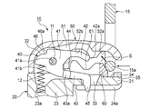
- the opening / closing member 60 is slid to a gap opening position that opens the insertion gap S, and the shaft portion 15a of the handle 15 is inserted into the insertion gap S, whereby the shaft portion 15a is inserted into the operating recess 44 of the lock member 40. Be contained.
- the shaft portion 15 a of the handle 15 is pushed forward from the rear into the insertion gap S, whereby the opening / closing member 60 slides forward, and the shaft portion 15 a of the handle 15 is moved toward the cover member 50.
- the opening / closing member 60 slides rearward, and the shaft portion 15 a of the handle 15 is formed on the upper surface of the opening / closing member 60, while entering the first recess 52 a formed on the lower surface of the rear end portion. Enter the recess 61.
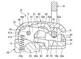
- the shaft portion 15 a of the handle 15 is pushed further forward in the insertion gap S, so that the opening / closing member 60 slides forward, and the shaft portion 15 a of the handle 15 is intermediate between the cover member 50.
- the opening / closing member 60 slides rearward and the shaft portion 15a of the pull handle 15 is moved into the second recess 52b formed on the lower surface of the portion. It is accommodated in 40 operating recesses 44.
- the lower piece 43 of the lock member 40 is bent with respect to the base 41 so as to be offset to one side in the width direction of the lock member 40.
- a step portion 46 having an end surface 46a extending in a direction intersecting with the front-rear direction of the lock member 40 is formed in the front and upper portion of the pin insertion hole 41a of the base portion 41 of the lock member 40.
- the leading lock member 40 in a state where the plurality of lock members 40 are loaded on the supply chute 100 at the tip of the upper piece 42 of the lock member 40. Since the end surface 42 a that contacts the end surface 46 a of the step portion 46 is formed, the end surface 42 a of the upper locking member 40 can be reliably pressed by the end surface 42 a of the upper piece portion 42, and the inside of the supply chute 100. The posture of the lock member 40 can be further stabilized.
- the stepped portion 46 extends while curving in an arc shape from the lower end of the end surface 46a toward the front and lower side of the lock member 40, and the bottom surface of the stepped portion 46 Since the curved surface 46b is formed, contact between the base 41 of the lock member 40 and the inner surface of the cover member 50 when the lock member 40 swings up and down can be avoided.
- the end surface 42 a may not be formed at the tip of the upper piece 42 of the lock member 40.
- the tip of the upper piece 42 of the rear lock member 40 is the leading position. While abutting against the end surface 46a of the stepped portion 46 of the locking member 40, the distal end portion of the lower piece 43 of the rearward locking member 40 is in the width direction (the back side of the paper surface in FIG. 13) of the leading locking member 40.
- an arrow X in FIG. 13 indicates the supply direction of the lock member 40 in the supply path 101 of the supply chute 100.
Landscapes
- Slide Fasteners (AREA)
Abstract
スライダーを小型化したとしても、供給シュート内におけるロック部材の詰まりを防止することができるスライドファスナー用スライダーを提供する。 スライドファスナー用スライダー10は、胴体20、ロック部材40、カバー部材50、ピン11、及び開閉部材60を備え、ロック部材40は、基部41と、基部41から後方に向けてそれぞれ延び、上下方向に対向して配置される上片部42及び下片部43と、を有し、下片部43は、基部41に対して、ロック部材40の幅方向一方側にオフセットするように折り曲げられ、基部41のピン挿通穴41aの前方且つ上方部分には、ロック部材40の前後方向と交差する方向に延びる端面46aを有する段差部46が形成されている。
Description
本発明は、スライドファスナー用スライダーに関し、より詳細には、引手を胴体に後付け可能なスライドファスナー用スライダーに関する。
従来のスライドファスナー用スライダーとしては、上翼板の案内柱から後口に向けて、下向き凹状のカバー部材が配設されており、カバー部材内の案内柱寄り位置にはロック部材が上下回動自在に装着され、ロック部材には、上翼板に開設された爪穴からファスナーエレメント列の位置に突出する爪部と、後口に向かって開口し引手の軸部を収容する作動凹部が形成され、且つロック部材は、爪部を常時爪穴から突出させるよう付勢されると共に、カバー部材の後口側の端部と上翼板との間の間隙が引手の軸部の挿通間隙とされ、この間隙を開閉する開閉部材が設けられるものが知られている(例えば、特許文献1参照)。
しかしながら、上記特許文献1に記載のスライドファスナー用スライダーでは、スライダーを小型化する場合、各構成部品の制約が増え、その中でもロック部材は、小型化に伴う板厚の減少と曲げ量の増加により、製造工程の供給シュート内における姿勢が不安定になり、供給シュート内で詰まって、供給不良を引き起こす可能性があった。
本発明は、前述した事情に鑑みてなされたものであり、その目的は、スライダーを小型化したとしても、供給シュート内におけるロック部材の詰まりを防止することができるスライドファスナー用スライダーを提供することにある。
本発明の上記目的は、下記の構成により達成される。
(1)胴体と、胴体の上面に立設される柱部に支持されるロック部材と、柱部及びロック部材を上方から覆うカバー部材と、柱部、ロック部材、及びカバー部材を貫通し、ロック部材の回転中心となるピンと、カバー部材の端部と胴体との間に形成され、引手の軸部が挿通される間隙を開閉する開閉部材と、を備え、ロック部材は、ピンが挿通されるピン挿通穴を有する基部と、基部から後方に向けてそれぞれ延び、上下方向に対向して配置される上片部及び下片部と、を有し、下片部の先端部に、胴体のエレメント案内路に入り込む爪部が形成されるスライドファスナー用スライダーであって、下片部は、基部に対して、ロック部材の幅方向一方側にオフセットするように折り曲げられ、基部のピン挿通穴の前方且つ上方部分には、ロック部材の前後方向と交差する方向に延びる端面を有する段差部が形成されていることを特徴とするスライドファスナー用スライダー。
(2)段差部は、端面の下端からロック部材の前方且つ下方に向けて円弧状に湾曲しながら延びる湾曲面を有することを特徴とする(1)に記載のスライドファスナー用スライダー。
(3)爪部がエレメント案内路に入り込むようにロック部材を付勢するばねを備え、基部のピン挿通穴の前方且つ下方部分には、ロック部材の上方へ段差状に窪み、ばねの付勢力を受けるばね受け面が形成されることを特徴とする(1)又は(2)に記載のスライドファスナー用スライダー。
(1)胴体と、胴体の上面に立設される柱部に支持されるロック部材と、柱部及びロック部材を上方から覆うカバー部材と、柱部、ロック部材、及びカバー部材を貫通し、ロック部材の回転中心となるピンと、カバー部材の端部と胴体との間に形成され、引手の軸部が挿通される間隙を開閉する開閉部材と、を備え、ロック部材は、ピンが挿通されるピン挿通穴を有する基部と、基部から後方に向けてそれぞれ延び、上下方向に対向して配置される上片部及び下片部と、を有し、下片部の先端部に、胴体のエレメント案内路に入り込む爪部が形成されるスライドファスナー用スライダーであって、下片部は、基部に対して、ロック部材の幅方向一方側にオフセットするように折り曲げられ、基部のピン挿通穴の前方且つ上方部分には、ロック部材の前後方向と交差する方向に延びる端面を有する段差部が形成されていることを特徴とするスライドファスナー用スライダー。
(2)段差部は、端面の下端からロック部材の前方且つ下方に向けて円弧状に湾曲しながら延びる湾曲面を有することを特徴とする(1)に記載のスライドファスナー用スライダー。
(3)爪部がエレメント案内路に入り込むようにロック部材を付勢するばねを備え、基部のピン挿通穴の前方且つ下方部分には、ロック部材の上方へ段差状に窪み、ばねの付勢力を受けるばね受け面が形成されることを特徴とする(1)又は(2)に記載のスライドファスナー用スライダー。
本発明のスライドファスナー用スライダーによれば、ロック部材の下片部は、基部に対して、ロック部材の幅方向一方側にオフセットするように折り曲げられ、ロック部材の基部のピン挿通穴の前方且つ上方部分には、ロック部材の前後方向と交差する方向に延びる端面を有する段差部が形成されているため、複数のロック部材を供給シュートに装填した際、後位のロック部材の上片部の先端部が先位のロック部材の段差部の端面に当接すると共に、後位のロック部材の下片部の先端部分が先位のロック部材の基部と幅方向においてオーバーラップする。これにより、後位のロック部材が先位のロック部材を移動方向と平行な方向に押圧するので、供給シュート内におけるロック部材の姿勢が安定して、ロック部材の詰まりを防止することができる。
なお、上記「先位のロック部材」とは、供給シュート内を先に移動しているロック部材であり、「後位のロック部材」とは、供給シュート内を後に移動しているロック部材である。
以下、本発明に係るスライドファスナー用スライダーの一実施形態について、図面に基づいて詳細に説明する。なお、以後の説明において、上側とは図3の紙面に対して上側、下側とは図3の紙面に対して下側、前側とは図3の紙面に対して左側、後側とは図3の紙面に対して右側、右側とは図3の紙面に対して奥側、左側とは図3の紙面に対して手前側とする。また、スライダーの左右方向は幅方向ともいう。
本実施形態のスライドファスナー用スライダー10は、引手後付け自動停止機能付きのスライダーであって、図1~図3に示すように、胴体20を備えており、この胴体20は、上下方向に離間して並行に配置される上翼板21及び下翼板22と、上翼板21及び下翼板22を前端部において連結する案内柱23と、上翼板21の左右両側縁に沿って下方に向けて突設される上側フランジ24aと、下翼板22の左右両側縁に沿って上方に向けて突設される下側フランジ24bと、を備える。これにより、胴体20の前部には案内柱23により分離された左右の肩口25が形成され、胴体20の後部には後口26が形成される。そして、上翼板21と下翼板22との間には、左右の肩口25と後口26とを連通する略Y字状のエレメント案内路27が形成され、このエレメント案内路27は、不図示のファスナーエレメント列を挿通させる通路を構成する。
また、スライドファスナー用スライダー10は、上翼板21の上面の前端部に立設される柱部31に上下に揺動可能に支持されるロック部材40と、柱部31及びロック部材40を上方から覆うカバー部材50と、柱部31、ロック部材40、及びカバー部材50を貫通し、ロック部材40の回転中心となるピン11と、カバー部材50の後端部と上翼板21との間に形成され、引手15の軸部15aが挿通される間隙S(以下、「挿通間隙S」と称する)を開閉する開閉部材60と、を備える。
ロック部材40は、図2~図6に示すように、ピン11が挿通されるピン挿通穴41aを有す基部41と、基部41から後方に向けてそれぞれ延び、上下方向に対向して配置される上片部42及び下片部43と、上片部42と下片部43との間に形成され、取付状態において、後口26側に向かって開口し、引手15の軸部15aを収容する作動凹部44と、を有する。また、下片部43の先端部には、上翼板21に形成される爪穴33を介してエレメント案内路27に入り込む爪部45が下方に向けて形成されている。なお、ピン挿通穴41aは、スライダー10の左右方向(幅方向)に沿って形成されている。また、爪穴33は、スライダー10の上下方向に沿って形成されている。
そして、図4に示すように、ロック部材40は、柱部31を構成する左右一対の支持片32,32間に挿入され、ロック部材40のピン挿通穴41a及び左右一対の支持片32,32のピン挿通穴32a,32aにピン11が挿通されることにより、胴体20に対して上下に揺動可能に軸支される。また、ピン11は、カバー部材50の左右一対の側面板51,51に形成される貫通穴51aに挿入されており、カバー部材50は、ピン11を介して柱部31に対して固定される。なお、ピン挿通穴32a及び貫通穴51aは、スライダー10の左右方向(幅方向)に沿って形成されている。
また、図3に示すように、ロック部材40は、スライダー10に内蔵された第1圧縮ばね12により、ロック部材40の爪部45がエレメント案内路27に入り込むように付勢されている。具体的には、ロック部材40の基部41の下面に形成されるばね受け面41bと案内柱23に形成されるばね保持孔23aとの間には、第1圧縮ばね12が縮設されており、ロック部材40は、この第1圧縮ばね12の付勢力をばね受け面41bが受けることによりピン11を支点にして揺動し、爪部45が爪穴33からエレメント案内路27に突出するように常時付勢されている。なお、ばね受け面41bは、ロック部材40の基部41のピン挿通穴41aの前方且つ下方部分において、ロック部材40の上方へ段差状に窪んだ面に形成される。このため、後述する段差部46を含めると、ロック部材40の基部41の前方には、上下に段差部分が形成される。また、ばね保持孔23aは、スライダー10の上下方向に沿って延びており、第1圧縮ばね12を載せるための底面を有する。また、ばねの形態は、上記第1圧縮ばね12に限定されない。例えば、板状のばねをロック部材40とカバー部材50との間に配置してもよい。この場合、ロック部材40は、板状のばねの付勢力をロック部材40の上片部42が受けることによりピン11を支点にして揺動し、爪部45が爪穴33からエレメント案内路27に突出するように常時付勢されることになる。
また、図3及び図5に示すように、ロック部材40の基部41のピン挿通穴41aの前方且つ上方部分には、ロック部材40の前後方向と交差する方向に延びる端面46aを有する段差部46が形成されている。また、上片部42の先端部には、段差部46の端面46aと略平行な端面42aが形成される。さらに、図4及び図6に示すように、下片部43の基端部に折曲部43aが形成されており、これにより、下片部43は、基部41に対して、ロック部材40の幅方向右側にオフセットするように折り曲げられている。
段差部46は、ロック部材40の下方へ段差状に窪んで形成される。また、段差部46は、端面46aの下端からロック部材40の前方且つ下方に向けて円弧状に湾曲しながら延び、段差部46の底面となる凸面状の湾曲面46bを有する。そして、段差部46では、端面46aと湾曲面46bとが交差するように配置されている。
そして、このように構成されたロック部材40の複数が図11に示すように供給シュート100の供給路101に装填された場合は、後位のロック部材40の上片部42の端面42aが先位のロック部材40の段差部46の端面46aに当接すると共に、後位のロック部材40の下片部43の先端部分が先位のロック部材40の基部41と幅方向(図11の紙面の奥側方向)においてオーバーラップする。これにより、後位のロック部材40が先位のロック部材40を移動方向と平行な方向に押圧するので、供給路101内におけるロック部材40の姿勢が安定して、ロック部材40の詰まりが防止される。なお、図11中の矢印Xは、供給シュート100の供給路101内におけるロック部材40の供給方向を示している。
開閉部材60は、図2及び図4に示すように、上翼板21の上面に胴体20の前後方向に沿って形成されるガイド溝34にスライド可能に装着される。また、開閉部材60の案内柱23側の端部とガイド溝34内に形成されるばね保持溝34aとの間には、第2圧縮ばね13が縮設されており、開閉部材60は、この第2圧縮ばね13の付勢力により、後口26側に常時付勢されている。
また、上翼板21の上面の後端部には、開閉部材60を挿通間隙Sを閉鎖する間隙閉鎖位置にて停止すると共に、開閉部材60のガイド溝34からの離脱を阻止する左右一対のストッパ35が形成される。そして、開閉部材60を挿通間隙Sを開放する間隙開放位置へとスライドさせ、引手15の軸部15aを挿通間隙Sに挿通させることにより、軸部15aは、ロック部材40の作動凹部44内に収容される。
次に、図7~図10を参照して、スライドファスナー用スライダー10に引手15を取り付ける手順を説明する。
まず、図7に示すように、引手15の軸部15aを挿通間隙S内に後方から前方に押し込むことにより、開閉部材60が前方にスライドして、引手15の軸部15aがカバー部材50の後端部の下面に形成される第1凹部52a内に入り込むと共に、図8に示すように、開閉部材60が後方にスライドして、引手15の軸部15aが開閉部材60の上面に形成される凹部61に入り込む。
次いで、図9に示すように、引手15の軸部15aを挿通間隙S内において更に前方に押し込むことにより、開閉部材60が前方にスライドして、引手15の軸部15aがカバー部材50の中間部の下面に形成される第2凹部52b内にロック部材40を上方に持ち上げながら入り込むと共に、図10に示すように、開閉部材60が後方にスライドして、引手15の軸部15aがロック部材40の作動凹部44内に収容される。
以上説明したように、本実施形態のスライドファスナー用スライダー10によれば、ロック部材40の下片部43は、基部41に対して、ロック部材40の幅方向一方側にオフセットするように折り曲げられ、ロック部材40の基部41のピン挿通穴41aの前方且つ上方部分には、ロック部材40の前後方向と交差する方向に延びる端面46aを有する段差部46が形成されているため、複数のロック部材40を供給シュート100に装填した際、後位のロック部材40の上片部42の先端部が先位のロック部材40の段差部46の端面46aに当接すると共に、後位のロック部材40の下片部43の先端部分が先位のロック部材40の基部41と幅方向においてオーバーラップする。これにより、後位のロック部材40が先位のロック部材40を移動方向と平行な方向に押圧するので、供給シュート100内におけるロック部材40の姿勢が安定して、ロック部材40の詰まりを防止することができる。
また、本実施形態のスライドファスナー用スライダー10によれば、ロック部材40の上片部42の先端部に、複数のロック部材40が供給シュート100に装填された状態において、先位のロック部材40の段差部46の端面46aに当接する端面42aが形成されるため、その上片部42の端面42aで先位のロック部材40の端面46aを確実に押圧することができ、供給シュート100内におけるロック部材40の姿勢を更に安定にすることができる。
また、本実施形態のスライドファスナー用スライダー10によれば、段差部46が、その端面46aの下端からロック部材40の前方且つ下方に向けて円弧状に湾曲しながら延び、段差部46の底面となる湾曲面46bを有するため、ロック部材40が上下に揺動する際における、ロック部材40の基部41とカバー部材50の内面との接触を回避することができる。
なお、本実施形態の変形例として、図12に示すように、ロック部材40の上片部42の先端部に端面42aは形成されなくてもよい。そして、本変形例のロック部材40の複数が図13に示すように供給シュート100の供給路101に装填された場合は、後位のロック部材40の上片部42の先端部が先位のロック部材40の段差部46の端面46aに当接すると共に、後位のロック部材40の下片部43の先端部分が先位のロック部材40の基部41と幅方向(図13の紙面の奥側方向)においてオーバーラップする。なお、図13中の矢印Xは、供給シュート100の供給路101内におけるロック部材40の供給方向を示している。
なお、本発明は上記実施形態に例示したものに限定されるものではなく、本発明の要旨を逸脱しない範囲において適宜変更可能である。
10 スライドファスナー用スライダー
11 ピン
15 引手
15a 軸部
20 胴体
27 エレメント案内路
31 柱部
40 ロック部材
41 基部
41a ピン挿通穴
41b ばね受け面
42 上片部
42a 端面
43 下片部
44 作動凹部
45 爪部
46 段差部
46a 端面
46b 湾曲面
50 カバー部材
60 開閉部材
S 挿通間隙
11 ピン
15 引手
15a 軸部
20 胴体
27 エレメント案内路
31 柱部
40 ロック部材
41 基部
41a ピン挿通穴
41b ばね受け面
42 上片部
42a 端面
43 下片部
44 作動凹部
45 爪部
46 段差部
46a 端面
46b 湾曲面
50 カバー部材
60 開閉部材
S 挿通間隙
Claims (3)
- 胴体(20)と、
前記胴体の上面に立設される柱部(31)に支持されるロック部材(40)と、
前記柱部及び前記ロック部材を上方から覆うカバー部材(50)と、
前記柱部、前記ロック部材、及び前記カバー部材を貫通し、前記ロック部材の回転中心となるピン(11)と、
前記カバー部材の端部と前記胴体との間に形成され、引手(15)の軸部(15a)が挿通される間隙(S)を開閉する開閉部材(60)と、を備え、
前記ロック部材は、前記ピンが挿通されるピン挿通穴(41a)を有する基部(41)と、前記基部から後方に向けてそれぞれ延び、上下方向に対向して配置される上片部(42)及び下片部(43)と、を有し、
前記下片部の先端部に、前記胴体のエレメント案内路(27)に入り込む爪部(45)が形成されるスライドファスナー用スライダー(10)であって、
前記下片部は、前記基部に対して、前記ロック部材の幅方向一方側にオフセットするように折り曲げられ、
前記基部の前記ピン挿通穴の前方且つ上方部分には、前記ロック部材の前後方向と交差する方向に延びる端面(46a)を有する段差部(46)が形成されていることを特徴とするスライドファスナー用スライダー。 - 前記段差部(46)は、前記端面(46a)の下端から前記ロック部材(40)の前方且つ下方に向けて円弧状に湾曲しながら延びる湾曲面(46b)を有することを特徴とする請求項1に記載のスライドファスナー用スライダー(10)。
- 前記爪部(45)が前記エレメント案内路(27)に入り込むように前記ロック部材(40)を付勢するばね(12)を備え、
前記基部(41)の前記ピン挿通穴(41a)の前方且つ下方部分には、ロック部材の上方へ段差状に窪み、前記ばねの付勢力を受けるばね受け面(41b)が形成されることを特徴とする請求項1又は2に記載のスライドファスナー用スライダー(10)。
Priority Applications (4)
| Application Number | Priority Date | Filing Date | Title |
|---|---|---|---|
| JP2013504463A JP5462978B2 (ja) | 2011-03-16 | 2011-03-16 | スライドファスナー用スライダー |
| PCT/JP2011/056284 WO2012124083A1 (ja) | 2011-03-16 | 2011-03-16 | スライドファスナー用スライダー |
| CN201180062934.2A CN103269615B (zh) | 2011-03-16 | 2011-03-16 | 拉链用拉头 |
| TW100128251A TWI444155B (zh) | 2011-03-16 | 2011-08-08 | Zipper with the slider |
Applications Claiming Priority (1)
| Application Number | Priority Date | Filing Date | Title |
|---|---|---|---|
| PCT/JP2011/056284 WO2012124083A1 (ja) | 2011-03-16 | 2011-03-16 | スライドファスナー用スライダー |
Publications (1)
| Publication Number | Publication Date |
|---|---|
| WO2012124083A1 true WO2012124083A1 (ja) | 2012-09-20 |
Family
ID=46830211
Family Applications (1)
| Application Number | Title | Priority Date | Filing Date |
|---|---|---|---|
| PCT/JP2011/056284 Ceased WO2012124083A1 (ja) | 2011-03-16 | 2011-03-16 | スライドファスナー用スライダー |
Country Status (4)
| Country | Link |
|---|---|
| JP (1) | JP5462978B2 (ja) |
| CN (1) | CN103269615B (ja) |
| TW (1) | TWI444155B (ja) |
| WO (1) | WO2012124083A1 (ja) |
Families Citing this family (1)
| Publication number | Priority date | Publication date | Assignee | Title |
|---|---|---|---|---|
| CN105231602B (zh) * | 2015-11-09 | 2017-09-12 | 晋江市金圣拉链科技有限公司 | 一种旋钮式针锁头 |
Citations (2)
| Publication number | Priority date | Publication date | Assignee | Title |
|---|---|---|---|---|
| JPH09183511A (ja) * | 1995-12-29 | 1997-07-15 | Hatano Tile:Kk | 役物タイル搬送装置 |
| JP2009106611A (ja) * | 2007-10-31 | 2009-05-21 | Ykk Corp | 自動停止機構付スライドファスナー用スライダー |
Family Cites Families (3)
| Publication number | Priority date | Publication date | Assignee | Title |
|---|---|---|---|---|
| JPS5637606Y2 (ja) * | 1976-09-20 | 1981-09-03 | ||
| JPH0432971Y2 (ja) * | 1986-12-19 | 1992-08-07 | ||
| CN101564220B (zh) * | 2008-04-21 | 2011-03-16 | 福建浔兴拉链科技股份有限公司 | 拉链滑块及使用该拉链滑块的拉链头 |
-
2011
- 2011-03-16 WO PCT/JP2011/056284 patent/WO2012124083A1/ja not_active Ceased
- 2011-03-16 CN CN201180062934.2A patent/CN103269615B/zh active Active
- 2011-03-16 JP JP2013504463A patent/JP5462978B2/ja active Active
- 2011-08-08 TW TW100128251A patent/TWI444155B/zh active
Patent Citations (2)
| Publication number | Priority date | Publication date | Assignee | Title |
|---|---|---|---|---|
| JPH09183511A (ja) * | 1995-12-29 | 1997-07-15 | Hatano Tile:Kk | 役物タイル搬送装置 |
| JP2009106611A (ja) * | 2007-10-31 | 2009-05-21 | Ykk Corp | 自動停止機構付スライドファスナー用スライダー |
Also Published As
| Publication number | Publication date |
|---|---|
| TWI444155B (zh) | 2014-07-11 |
| JPWO2012124083A1 (ja) | 2014-07-17 |
| CN103269615B (zh) | 2015-09-23 |
| CN103269615A (zh) | 2013-08-28 |
| TW201238513A (en) | 2012-10-01 |
| JP5462978B2 (ja) | 2014-04-02 |
Similar Documents
| Publication | Publication Date | Title |
|---|---|---|
| JP5647728B2 (ja) | スライドファスナー用スライダー | |
| US9271548B2 (en) | Slider for slider fasteners | |
| JP5647730B2 (ja) | スライドファスナー用スライダー | |
| TWI376211B (ja) | ||
| EP2382888B1 (en) | Slide fastener | |
| TWI583322B (zh) | Zipper with slider | |
| JPWO2002070209A1 (ja) | ステープラー | |
| CN102686122B (zh) | 拉链用拉头 | |
| CN102665474A (zh) | 拉链用拉头 | |
| CN101224057B (zh) | 带自动停止装置的拉链用拉链头 | |
| ITTO20100002A1 (it) | Cursore sottile per chiusure lampo. | |
| JP6462136B2 (ja) | パーティングロック装置とそれを用いた射出成形金型 | |
| CN201995749U (zh) | 拉链拉头、使用该拉链拉头的拉链及使用该拉链的物品 | |
| CN107404980B (zh) | 拉头及拉链 | |
| JP5462978B2 (ja) | スライドファスナー用スライダー | |
| WO2013011591A1 (ja) | スライドファスナー用スライダー | |
| TWI459914B (zh) | Zipper with the slider | |
| WO2013011592A1 (ja) | スライドファスナー用スライダー | |
| JP5844386B2 (ja) | 停止機構付きスライダー | |
| TWI510201B (zh) | Zipper with slider | |
| CN103763968A (zh) | 拉链用拉头 | |
| JP3205204U (ja) | スライドファスナー用スライダー | |
| CN102755015A (zh) | 关闭装置的抵接构造 | |
| CN103517651A (zh) | 拉链用拉头 | |
| CN201009223Y (zh) | 打钉枪枪匣启闭控制装置 |
Legal Events
| Date | Code | Title | Description |
|---|---|---|---|
| 121 | Ep: the epo has been informed by wipo that ep was designated in this application |
Ref document number: 11861185 Country of ref document: EP Kind code of ref document: A1 |
|
| ENP | Entry into the national phase |
Ref document number: 2013504463 Country of ref document: JP Kind code of ref document: A |
|
| NENP | Non-entry into the national phase |
Ref country code: DE |
|
| 122 | Ep: pct application non-entry in european phase |
Ref document number: 11861185 Country of ref document: EP Kind code of ref document: A1 |