WO2012120794A1 - 面光源装置および液晶表示装置 - Google Patents
面光源装置および液晶表示装置 Download PDFInfo
- Publication number
- WO2012120794A1 WO2012120794A1 PCT/JP2012/001068 JP2012001068W WO2012120794A1 WO 2012120794 A1 WO2012120794 A1 WO 2012120794A1 JP 2012001068 W JP2012001068 W JP 2012001068W WO 2012120794 A1 WO2012120794 A1 WO 2012120794A1
- Authority
- WO
- WIPO (PCT)
- Prior art keywords
- light source
- screen
- source device
- led
- light sources
- Prior art date
- Legal status (The legal status is an assumption and is not a legal conclusion. Google has not performed a legal analysis and makes no representation as to the accuracy of the status listed.)
- Ceased
Links
Images



Classifications
-
- F—MECHANICAL ENGINEERING; LIGHTING; HEATING; WEAPONS; BLASTING
- F21—LIGHTING
- F21V—FUNCTIONAL FEATURES OR DETAILS OF LIGHTING DEVICES OR SYSTEMS THEREOF; STRUCTURAL COMBINATIONS OF LIGHTING DEVICES WITH OTHER ARTICLES, NOT OTHERWISE PROVIDED FOR
- F21V21/00—Supporting, suspending, or attaching arrangements for lighting devices; Hand grips
-
- G—PHYSICS
- G02—OPTICS
- G02F—OPTICAL DEVICES OR ARRANGEMENTS FOR THE CONTROL OF LIGHT BY MODIFICATION OF THE OPTICAL PROPERTIES OF THE MEDIA OF THE ELEMENTS INVOLVED THEREIN; NON-LINEAR OPTICS; FREQUENCY-CHANGING OF LIGHT; OPTICAL LOGIC ELEMENTS; OPTICAL ANALOGUE/DIGITAL CONVERTERS
- G02F1/00—Devices or arrangements for the control of the intensity, colour, phase, polarisation or direction of light arriving from an independent light source, e.g. switching, gating or modulating; Non-linear optics
- G02F1/01—Devices or arrangements for the control of the intensity, colour, phase, polarisation or direction of light arriving from an independent light source, e.g. switching, gating or modulating; Non-linear optics for the control of the intensity, phase, polarisation or colour
- G02F1/13—Devices or arrangements for the control of the intensity, colour, phase, polarisation or direction of light arriving from an independent light source, e.g. switching, gating or modulating; Non-linear optics for the control of the intensity, phase, polarisation or colour based on liquid crystals, e.g. single liquid crystal display cells
- G02F1/133—Constructional arrangements; Operation of liquid crystal cells; Circuit arrangements
- G02F1/1333—Constructional arrangements; Manufacturing methods
- G02F1/1335—Structural association of cells with optical devices, e.g. polarisers or reflectors
- G02F1/1336—Illuminating devices
- G02F1/133602—Direct backlight
- G02F1/133603—Direct backlight with LEDs
-
- F—MECHANICAL ENGINEERING; LIGHTING; HEATING; WEAPONS; BLASTING
- F21—LIGHTING
- F21V—FUNCTIONAL FEATURES OR DETAILS OF LIGHTING DEVICES OR SYSTEMS THEREOF; STRUCTURAL COMBINATIONS OF LIGHTING DEVICES WITH OTHER ARTICLES, NOT OTHERWISE PROVIDED FOR
- F21V7/00—Reflectors for light sources
- F21V7/0066—Reflectors for light sources specially adapted to cooperate with point like light sources; specially adapted to cooperate with light sources the shape of which is unspecified
-
- G—PHYSICS
- G02—OPTICS
- G02F—OPTICAL DEVICES OR ARRANGEMENTS FOR THE CONTROL OF LIGHT BY MODIFICATION OF THE OPTICAL PROPERTIES OF THE MEDIA OF THE ELEMENTS INVOLVED THEREIN; NON-LINEAR OPTICS; FREQUENCY-CHANGING OF LIGHT; OPTICAL LOGIC ELEMENTS; OPTICAL ANALOGUE/DIGITAL CONVERTERS
- G02F1/00—Devices or arrangements for the control of the intensity, colour, phase, polarisation or direction of light arriving from an independent light source, e.g. switching, gating or modulating; Non-linear optics
- G02F1/01—Devices or arrangements for the control of the intensity, colour, phase, polarisation or direction of light arriving from an independent light source, e.g. switching, gating or modulating; Non-linear optics for the control of the intensity, phase, polarisation or colour
- G02F1/13—Devices or arrangements for the control of the intensity, colour, phase, polarisation or direction of light arriving from an independent light source, e.g. switching, gating or modulating; Non-linear optics for the control of the intensity, phase, polarisation or colour based on liquid crystals, e.g. single liquid crystal display cells
- G02F1/133—Constructional arrangements; Operation of liquid crystal cells; Circuit arrangements
- G02F1/1333—Constructional arrangements; Manufacturing methods
- G02F1/1335—Structural association of cells with optical devices, e.g. polarisers or reflectors
- G02F1/1336—Illuminating devices
- G02F1/133602—Direct backlight
- G02F1/133611—Direct backlight including means for improving the brightness uniformity
Definitions
- the present invention relates to a surface light source device such as an LED light source device in which one or a plurality of LED modules on which one or a plurality of point light sources such as one or a plurality of light emitting diodes (LEDs) are mounted, and the surface light source device.
- the present invention relates to a liquid crystal display device used as a backlight.
- This type of conventional liquid crystal display device has a transmissive liquid crystal panel and a backlight behind the liquid crystal panel.
- FIG. 8 shows how to improve the brightness of the center of the screen while reducing the number of LEDs mounted.
- FIG. 8 is a plan view schematically showing an LED module arrangement example in a conventional LED light source device.
- a conventional LED light source device 100 is composed of a plurality of LED modules 101.
- strip-like LED modules 101 are arranged in four rows in the horizontal direction.
- the two rows of strip-shaped LED modules 101 in the center are arranged close to each other in order to improve the luminance at the center of the screen.
- Each LED module 101 has a printed wiring board 102 and a plurality (in this case, ten) of LEDs 103 mounted thereon.
- the reflection sheet 104 has a plurality of holes through which the LEDs 103 penetrate, and the printed wiring board 102 and the reflection sheet 104 are fixed in a state where the LEDs 103 penetrate the LED through holes from the back side. Light from the plurality of LEDs 103 is reflected by the reflection sheet 104 and emitted forward to be a surface light source.
- the screen peripheral portion (screen peripheral frame portion) of the reflection sheet 104 is configured by four long, vertical and horizontal surfaces that are inclined so as to open forward.
- Patent Document 1 discloses an example in which a plurality of LED modules in a central row are brought closer to the center side and LEDs are arranged at a higher density than the peripheral portion in order to improve the luminance of the central portion of the screen. Yes.
- the LED array pitch is moved to the inside of the screen, and the periphery of the screen is configured by the inclination of the reflection sheet.
- the brightness around the screen is somewhat low.
- the display quality is likely to deteriorate due to insufficient brightness.
- the amount of light reaching the four corners A of the screen is insufficient to improve the brightness at the center of the screen, such as when reducing the number of LEDs or pursuing a thinner backlight.
- the phenomenon that the four corners A of the screen become dark is likely to occur.
- the present invention solves the above-described conventional problems, such as an LED light source device that can improve the display quality at the four corners of the screen by reducing the number of light sources in the surface light source while maintaining and improving the brightness at the center of the screen. It is an object of the present invention to provide a surface light source device and a liquid crystal display device using the surface light source device as a backlight.
- the surface light source device of the present invention is a surface light source device that irradiates light in a planar shape by arranging a plurality of tubular light sources with high density at the center of the screen so that the luminance at the center of the screen is high. Either or the end of the tubular light source located at the outermost periphery is brought close to or added to the four corners of the plan view screen so as to compensate for insufficient luminance at the four corners of the plan view screen, and the tubular light source is arranged. This achieves the above object.
- At least one of the lowermost left and right end rows or the outermost peripheral tubular light source is divided into at least two tubular light sources, and the divided at least two tubular light sources are adjacent to each other.
- the two tubular light sources are arranged such that end portions other than the end portions are respectively brought close to the four-corner side of the planar view screen.
- a tubular light source located at least one of the lowermost left and right end rows or the outermost periphery in the surface light source device of the present invention is integrally provided, and both end portions of the integral tubular light source are respectively viewed in plan view.
- the integral tubular light source is arranged on the four corners side.
- the position of the point light source at the end of the tubular light source located at the four corners of the planar light source located at the outermost periphery or at least one of the lowermost left and right end rows in the surface light source device of the present invention is: It is determined that the four corners of the planar view screen do not become darker than the brightness of the entire screen.
- the end portions other than the opposing end portions of the two tubular light sources in the surface light source device of the present invention are brought close to the four corners of the planar view screen, and the opposing end portions of the two tubular light sources are arranged.
- the two tubular light sources are arranged so as to be inclined in plan view so as to approach the central portion.
- the plurality of tubular light sources in the surface light source device of the present invention are arranged so that the arrangement pitch is brought closer to the center side of the plane view screen and the center side of the plane view screen is in a dense state.
- the tubular light source in the surface light source device of the present invention is a tubular light source having the same structure or a tubular light source having a different structure.
- the tubular light source in the surface light source device of the present invention has a printed wiring board and one or a plurality of point light sources mounted on the printed wiring board.
- each of the one or more point light sources in the surface light source device of the present invention or one or more light diffusion lenses for diffusing light over the one or more point light sources passes through each hole.
- Reflecting means for reflecting the light emitted from each of the plurality of point light sources forward and illuminating it in a planar shape is provided.
- the reflecting means in the surface light source device of the present invention is constituted by four long, vertical and horizontal surfaces each having an inclined surface so that the periphery of the screen opens forward.
- a plurality of point light sources mounted on the tubular light source are arranged at a low density so that light is extracted on an inclined surface around the reflecting means.
- the tubular light source in the surface light source device of the present invention is an LED module or a fluorescent lamp means.
- the point light source in the surface light source device of the present invention is LED means or laser element means.
- the liquid crystal display device of the present invention is the above-described one of the present invention, and thereby the above object is achieved.
- a surface light source device that irradiates light in a planar manner by arranging a plurality of tubular light sources at a high density at the center of the screen so that the brightness at the center of the screen is high, at least one of the lowermost left and right end rows or The tubular light source is arranged such that the end of the tubular light source located at the outermost periphery is brought close to or added to the four corners of the planar view screen so as to compensate for the lack of luminance at the four corners of the planar view screen.
- a surface light source device that irradiates light in a planar shape by arranging a plurality of tubular light sources at a high density in the center of the screen so that the brightness at the center of the screen is increased, the shortage of brightness at the four corners of the planar view screen is compensated. Since the tubular light source located at the outermost periphery or at least one of the lowermost left and right end rows is arranged near the four corners of the planar view screen, the luminance at the center of the screen is reduced while reducing the number of light sources in the surface light source. The display quality at the four corners of the screen can be improved by maintaining and improving.
- a surface light source device that irradiates light in a planar shape by arranging a plurality of tubular light sources with high density at the center of the screen so that the luminance at the center of the screen is high, Since a tubular light source located at the outermost periphery or at least one of the lowermost left and right end rows is arranged close to the four corners of the planar view screen to compensate for the lack of brightness, the surface light source is reduced in light source. By maintaining and improving the brightness at the center of the screen, the display quality at the four corners of the screen can be improved.
- FIG. 1 It is a top view which shows typically the example of LED module arrangement
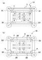
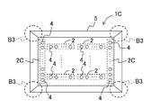
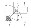
- (A) And (b) is a top view which shows typically the modification of the LED module arrangement example of the LED light source device of FIG. It is a top view which shows typically the other modification of the LED module arrangement example of the LED light source device of FIG. It is a top view which shows typically the examination example of the LED position for supplementing the brightness
- Embodiments 1 and 2 a case where the surface light source device of the present invention is applied to an LED light source device will be referred to as Embodiments 1 and 2, and an embodiment of a liquid crystal display device using any one of Embodiments 1 and 2 of the LED light source device as a backlight will be described. 3 will be described in detail with reference to the drawings.
- each thickness, length, etc. of the structural member in each figure are not limited to the structure to illustrate from a viewpoint on drawing preparation.
- FIG. 1 is a plan view schematically showing an LED module arrangement example of the LED light source device according to Embodiment 1 of the present invention.
- an LED light source device 1 is composed of a plurality of LED modules 2.
- long and strip-like LED modules 2 are arranged in four rows in the horizontal direction.
- the LED strips 2 in the center 2 rows are arranged closer to the center side so that the LEDs on the center side are closer to each other. They are arranged in a dense state.
- Each LED module 2 has a printed wiring board 3 and a plurality (in this case, five) of LEDs 4 mounted thereon.
- Each LED module 2 in a row is composed of two LED modules 2 here, and the two LED modules 2 are arranged so that the arrangement pitch of the LEDs 4 is equal.
- each of the LED modules 2 in the peripheral portion of the screen in particular, the uppermost lowermost row, has two LED modules 2 arranged in a row, but one outer end other than the opposite ends of the LED modules 2. 4 side of the reflection sheet 5 so that the amount of light reaching the four corners (four corners) B of the reflection sheet 5 as the reflection means is not insufficient (so as to compensate for the insufficient luminance of the four corners B in plan view).
- Each LED module 2 is arranged close to each other.
- the luminance with which the amount of light reaching the four corners B is not insufficient means that the four corners B are particularly dark and light with no sense of incongruity in the surface emission of the entire screen.
- the opposing ends of the two LED modules 2 are spaced apart by the amount of the shift. Yes.
- the two LED modules 2 are brought close to the four corners of the reflection sheet 5 by the distance between the separated edges, and each LED module 2 is arranged so that a sufficient amount of light reaches the screen corner B. .
- the reflection sheet 5 has a plurality of holes through which the lenses 7 (FIG. 5) mounted on the LED 4 pass, and the number of the LEDs 4 is open at a predetermined arrangement position.
- the LED through holes are mounted on the LED 4.
- the printed wiring board 3 and the reflection sheet 5 are fixed with the lens 7 penetrating from the back side of the reflection sheet 5. Light from the plurality of LEDs 4 is reflected by the reflection sheet 5 through the lens and emitted forward.
- the LED light source device 1 is a surface light source.
- the screen peripheral part (screen peripheral frame part) of the reflection sheet 5 four elongated vertical and horizontal surfaces are each configured by an inclined surface 5 a (FIG. 5) so as to open forward.
- the plurality of LED modules 2 in the center row are moved closer to the center and the LEDs 4 are arranged at a high density in the center, and the LEDs 4 are arranged at a low density at the periphery of the screen.
- light is extracted at an inclined portion around the reflection sheet 5.
- the outermost LED array 2 or the outermost peripheral LED module 2 is divided into at least two LED modules 2, and the ends of the two LED modules 2 other than the opposite ends.
- Each LED module 2 is arranged with the portion side being brought close to the four corners B side of the reflection sheet 5.
- the planar view screen In the LED light source device 1 in which a plurality of LED modules 2 are arranged at a high density in the center of the screen so that the luminance at the center of the screen is high and light is irradiated in a planar shape, the planar view screen
- the LED modules 2 located in the uppermost lower end row (or the leftmost and rightmost end rows) are arranged close to the four corners of the planar view screen so as to compensate for the luminance deficiency at the four corners.
- the LED modules 2 in the uppermost lower end row are arranged in the row direction (longitudinal direction of the LED module 2) on the four corners B side of the reflection sheet 5. Therefore, even when the number of LEDs of the LED module 2 is reduced and the luminance at the center of the screen is improved, the light quantity of the screen corner B can be supplemented to improve the display quality of the screen corner B. .
- one row of LED modules positioned in the uppermost lower end row is divided into two LED modules 2, and the outer end portions other than the inner end portions adjacent to each other of the two divided LED modules 2 are divided.
- a case has been described in which two LED modules 2 are arranged so that the sides are brought close to the four-corner portion side in plan view together with the LEDs 4 mounted on the LED module 2 so as to compensate for the luminance deficiency of the four-corner portion B in plan view.
- the present invention is not limited to this, and not only the uppermost lower end row in the horizontal direction, but also the LED module end portion located at the outermost periphery or at least one of the lowermost left and right end rows in the vertical and horizontal direction together with the LEDs mounted on the plane.
- the LED module may be arranged close to the plan view corner B so as to compensate for the luminance shortage of the view corner B.
- the LED modules in the outermost end row (here, the uppermost lower end row) or the outermost periphery (here, the uppermost lower end side) are divided into at least two LED modules 2, and the four corners of the reflective sheet 5 are separated.
- each LED module 2 is arranged close to the part B side, the present invention is not limited to this, and as shown in FIG. 2 (a), as shown in FIG.
- each of the LED modules 2A may be integrated with the four corners of the reflective sheet 5 as in the case of the four corners B1 in a plan view, rather than when the two LED modules 2 are arranged in a row.
- the LED modules 2 at the outermost end rows or the outermost periphery are respectively brought closer to the four corners B1 side of the reflection sheet 5 so that the other end sides of the LED modules 2 are separated from each other at the center side of the same row. For this reason, it is possible to prevent the possibility of insufficient luminance at the spaced opposite ends.
- two dedicated LED modules in the outermost row or outermost periphery of the LED light source device 1B 2B can also be used in a row.
- two dedicated LED modules 2B are arranged on the four-corner side of the reflection sheet 5 in a state of extending together with the LEDs 4 as in the four-cornered corner B2 in a plan view of FIG.
- the long LED module 2 ⁇ / b> C dedicated for the outermost row (here, the left and right end rows) or the outermost periphery (here, the left and right ends) in the vertical direction in the LED light source device 1 ⁇ / b> C is arranged in the vertical direction. You may use it by extending in one line.
- the end portion of the dedicated LED module 2C is arranged in the state where the LED 4 is extended (added) to the four corner portions of the reflection sheet 5 like the four corner portions B3 in plan view in FIG. Make up for the lack of light.
- the vertical direction may be used, but here the central luminance is increased so that the two LED modules 2 in the horizontal direction are arranged in a row, and the LED modules 2 are concentrated in the center. It may be provided as follows. Further, the dedicated long LED module 2C in the vertical direction may be divided into two or three as in the case of FIG.
- the LED modules 2A and 2C located at least one of the lowermost left and right end rows or the outermost periphery are integrally provided, and both ends of the integrated LED modules 2A and 2C are viewed in plan view together with the LEDs 4 respectively.
- Integrated LED modules 2A and 2C are arranged close to the four corner portions B1 and B3.
- the positions of the LEDs 4 at the ends of the LED modules 2A and 2C on the side of the four corners B1 and B3 in the plan view of the LED modules 2A and 2C located in the lowermost left and right end rows are the four corners B1 and B3 in the plan view.
- the luminance difference between the central portion and the four corner portions B1 and B3 is determined to be equal to or less than a predetermined value so as not to darken the entire screen. This is the same even when the LED modules in the same row are divided into two or three.
- the LED module 2 needs to be positioned within the radius range of the distance r necessary to supplement the luminance with respect to the luminance deficient region S at the four corners, and the LED module 2 exists so that the LED 4 exists within the radius range of the distance r. May be arranged.
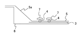
- FIG. 5 is a vertical cross-sectional view of the four corners of the LED light source device 1 of FIG.
- the reflection sheet 5 having the inclined surface 5 a provided in the peripheral portion is disposed on the BL chassis 6, and the lens 7 mounted on the LED 4 is inserted into the LED through hole of the reflection sheet 5.
- the printed wiring board 3 and the reflection sheet 5 are fixed in a state of penetrating from the back side of the reflection sheet 5.
- the LED light source device 1 is configured in which the light passing from the LED 4 through the lens 7 is reflected forward by the reflection sheet 5 to be a surface light source.
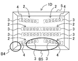
- FIG. 6 is a plan view schematically showing an LED module arrangement example of the LED light source device according to Embodiment 2 of the present invention.
- the LED light source device 1 ⁇ / b> D of Embodiment 2 includes a plurality of LED modules 2, and here, for convenience, four rows in the horizontal direction and a long and strip-like structure with the same number of LEDs mounted. LED modules 2 are arranged. Of the four LED strips 2 in the horizontal direction, in order to improve the luminance at the center of the screen, the LED strips 2 in the center two rows have their arrangement pitches closer to the center side so that the LEDs 4 on the center side They are arranged in a dense state.
- Each LED module 2 has a printed wiring board 3 and a plurality (in this case, five) of LEDs 4 mounted thereon.
- Each LED module 2 in a row is composed of two LED modules 2 here, and the two LED modules 2 are arranged so that the arrangement pitch of the LEDs 4 is equal.
- each LED module 2 in the row at the uppermost and lowermost ends of the screen has two LED modules 2 arranged in a row, but the outer end of the LED module 2 is connected to the reflection sheet 5.
- the LED modules 2 are arranged close to the four corners of the reflection sheet 5 so that the amount of light reaching the four corners B4 (four corners of the screen) is not insufficient. Therefore, even if at least two LED modules 2 in the uppermost row and the lowermost row are arranged in a single row, the two LED modules 2 are separated from each other by that amount and the amount of light at the screen center B5 In order to compensate, each L is moved to the corner B4 and also to the screen center B5.
- the ED module 2 is disposed obliquely in plan view. The two LED modules 2 are respectively brought close to the four corners of the reflection sheet 5 and compensated for light at the center of the screen so that a sufficient amount of light reaches the four corners A of the screen by the distance and inclination. Each LED module 2 can be arranged.
- the reflection sheet 5 has a plurality of holes, through which the lenses 7 mounted on the LEDs 4 penetrate, as many as the number of the LEDs 4, and are arranged at predetermined positions.
- the lenses 7 mounted on the LEDs 4 have through holes for LEDs.
- the printed wiring board 3 and the reflection sheet 5 are fixed in a state of penetrating from the back side of the reflection sheet 5. Light from the plurality of LEDs 4 is reflected by the reflection sheet 5 through the lens and emitted forward.
- the LED light source device 1D is a surface light source.
- the screen peripheral part (screen peripheral frame part) of the reflection sheet 5 the long and four vertical and horizontal surfaces are each comprised by the inclined surface 5a so that it may open ahead.
- the plurality of LED modules 2 in the center row are moved closer to the center and the LEDs 4 are arranged at a high density in the center, and the LEDs 4 are arranged at a low density at the periphery of the screen.
- light is extracted at an inclined portion around the reflection sheet 5.
- the LED modules 2 in the outermost row or outermost periphery are divided into at least two LED modules 2 so that one end is brought close to the four corners of the reflection sheet 5 and the other end is brought close to the center.
- Each LED module 2 is inclined and arranged in plan view.
- the space between the two LED modules 2 is vacant, and the light on the center side is reduced.
- the other ends of the two LED modules 2 are placed on the center side.
- the upper and lower LED modules 2 are divided into two parts, and one end of each LED module 2 is divided.
- the LED module 2 is disposed so as to be inclined in plan view so as to be brought close to the corner of the reflection sheet 5 and the other end to the center.
- the LED module 2 that is the LED substrate of the same structure, the brightness of the center of the screen is improved while reducing the number of LEDs of the LED module only by arrangement, and the display quality at the four corners of the screen is improved. Has also improved.
- each LED module is arranged such that one end of the LED module 2 at the extreme end is brought close to the four corners of the reflection sheet 5 and the other end of the LED module 2 is brought close to the center side. Since 2 is inclined, the distance from the LED 4 is reduced at the four corners of the reflection sheet 5 to suppress a decrease in luminance at the four corners of the reflection sheet 5 and each LED module 2 is arranged obliquely. As a result, the luminance change from the center side to the surroundings becomes gradual, and luminance unevenness is reduced. In this way, it is possible to improve the display quality at the four corners of the screen by reducing the number of LEDs of the LED module and improving the luminance at the center of the screen.
- any one of the LED light source devices 1 and 1A to 1D in FIGS. 1 to 3 and 6 can be incorporated in the liquid crystal display device as a backlight.
- FIG. A case where the LED light source device 1 is incorporated in a liquid crystal display device as a backlight will be described with reference to FIG.
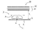
- FIG. 7 is a longitudinal sectional view schematically showing an example of the configuration of the main part of a liquid crystal display device incorporating the LED light source device 1 of FIG.
- the LED light source device 1 which is a LED backlight in which a plurality of the LED modules 2 are arranged at the four corners and arranged so as to emit light, and above the LED light source device 1 from the reflection sheet 5. It has an optical sheet 21 including a light diffusion sheet provided with a distance L, and a light transmission type liquid crystal panel 22 that enables liquid crystal image display based on a display signal.
- the LED light source device 1 has a plurality of LED modules 2 in the center row arranged close to each other to increase the brightness at the center of the screen and arranges the LEDs 4 at a high density in the center, and the LEDs 4 are arranged at a low density at the periphery of the screen.
- the light is extracted at the inclined portion (inclined surface 5a) around the reflective sheet 5.
- the outermost end row or outermost LED module 2 is divided into at least two LED modules 2, and each of the LED sheet 2 is arranged on the four corners side of the reflection sheet 5.
- the LED modules 2 are arranged at the same time.
- the LED module 2 includes a plurality of LEDs 4 provided on each printed wiring board 3 and each LED. 4 has each light diffusion lens 8 covering the top.
- any one of the LED light source devices 1 and 1A to 1D that irradiate light in a planar shape by arranging a plurality of LED modules with a high density at the center of the screen so that the luminance at the center of the screen is increased.
- at least one of the lowermost left and right end rows or the end of the LED module located at the outermost periphery together with one or a plurality of LEDs mounted on the end of the LED module compensates for insufficient luminance at the four corners of the planar view screen.
- any one of the LED light source devices 1 and 1A to 1D in which the LED modules are arranged or expanded toward the four corners of the planar view screen is provided on the back side of the light transmission type liquid crystal panel 22 and is backlit. It is used as.
- the liquid crystal display device 20 according to the third embodiment can irradiate light in a planar shape without any particularly dark corners on the entire screen because the lack of brightness on the corners side of the planar view screen is resolved. A good image without a sense of incongruity can be displayed.
- the surface light source device of the present invention is applied to the LED light source devices 1 and 1A to 1D. That is, in the first to third embodiments, in the LED light source devices 1 and 1A to 1D in which a plurality of LED modules 2 are arranged with a high density at the center of the screen so that the luminance at the center of the screen is high and light is irradiated in a planar shape,
- the LED modules 2, 2A to 2C located in the uppermost and lowermost rows (or the left and right end rows) are arranged close to or added to the four corners of the planar screen so as to compensate for insufficient luminance at the corners of the screen.
- a fluorescent lamp means having a fluorescent lamp can be used instead of these LED modules 2, 2A to 2C.
- the planar view screen is to compensate for the lack of brightness at the four corners of the planar view screen.
- the surface light source device of the present invention is applied to the LED light source devices 1 and 1A to 1D, and the LED 4 (including the light emitter) as the LED means is used for white or white color.
- the present invention is not limited to this, and it is also possible to obtain a white or white color using a laser element and a light emitter as laser element means.
- the number of light sources can be increased by bringing or increasing the number of laser elements (including light emitters) mounted on the substrate on the side of the four corners of the plan view screen so as to compensate for the lack of brightness at the four corners of the plan view screen.
- the object of the present invention that can improve the display quality at the four corners of the screen by improving the brightness at the center of the screen can be achieved.
- the LED module or the fluorescent lamp means can be a tubular light source.
- LED means or laser element means can be used as a point light source. If a plurality of the point light sources are arranged side by side on the substrate, a tubular light source is obtained.
- the tubular light source includes a module in which a plurality of laser element means as point light sources are arranged side by side on a substrate.
- the surface light source device of the present invention is a surface light source device that irradiates light in a planar shape by arranging a plurality of tubular light sources at a high density at the center of the screen so that the luminance at the center of the screen is high.
- the end of the tubular light source located in at least one of the outermost periphery or the end of the tubular light source is brought close to or added to the four corners of the planar view screen so as to compensate for the lack of brightness of the four corners of the planar view screen. Has been placed. Accordingly, it is possible to achieve the object of the present invention that can improve the display quality at the four corners of the screen by improving the luminance at the center of the screen while reducing the number of light sources.
- the present invention relates to an LED light source device in which one or a plurality of LED modules on which one or a plurality of light emitting diodes (LEDs) are mounted, and a liquid crystal display device in which the LED light source device is used as a backlight.
- the display quality at the four corners of the screen can be improved by reducing the number of LEDs in the module and improving the brightness at the center of the screen.
Landscapes
- Physics & Mathematics (AREA)
- Nonlinear Science (AREA)
- Mathematical Physics (AREA)
- Chemical & Material Sciences (AREA)
- Crystallography & Structural Chemistry (AREA)
- General Physics & Mathematics (AREA)
- Optics & Photonics (AREA)
- Engineering & Computer Science (AREA)
- General Engineering & Computer Science (AREA)
- Planar Illumination Modules (AREA)
- Liquid Crystal (AREA)
Abstract
Description
2、2A~2C LEDモジュール(管状光源)
3 プリント配線基板
4 LED(点光源)
5 反射シート
5a 傾斜面
6 BLシャーシ
7 レンズ
8 光拡散レンズ
20 液晶表示装置
21 光学シート
22 光透過型液晶パネル
B,B1~B4 4角部
B5 画面中央部
S 4角部の輝度不足領域
r 距離
d LEDから反射シートの端部までの距離
図1は、本発明の実施形態1におけるLED光源装置のLEDモジュール配置例を模式的に示す平面図である。
図6は、本発明の実施形態2におけるLED光源装置のLEDモジュール配置例を模式的に示す平面図である。
EDモジュール2が平面視で斜めに傾いて配置されている。この離間しかつ傾いた分だけ、二つのLEDモジュール2はそれぞれ反射シート5の4角部にそれぞれ寄せられかつ画面中央部側にも光を補って、画面四隅Aにも十分な光量が届くように各LEDモジュール2を配置することができる。
本実施形態3の液晶表示装置では、図1~図3および図6のLED光源装置1および1A~1Dのいずれかをバックライトとして液晶表示装置に組み込むことができるが、ここでは、図1のLED光源装置1をバックライトとして液晶表示装置に組み込んだ場合について図7を用いて説明する。
4上をそれぞれ覆う各光拡散レンズ8を有している。
Claims (14)
- 画面中央の輝度が高くなるように複数の管状光源を該画面中央で密度を高く配列して面状に光照射する面光源装置において、
最上下左右端列の少なくともいずれかまたは最外周辺に位置する管状光源の端部を、平面視画面4角部の輝度不足を補うように該平面視画面4角部側に寄せるかまたは増設して該管状光源が配置されている面光源装置。 - 前記最上下左右端列の少なくともいずれかまたは最外周辺に位置する管状光源を少なく
とも二つの管状光源に分け、分けた少なくとも二つの管状光源の互いに隣接する端部以外の端部側をそれぞれ平面視画面4角部側に寄せて該二つの管状光源が配置されている請求項1に記載の面光源装置。 - 前記最上下左右端列の少なくともいずれかまたは最外周辺に位置する管状光源を一体的に設け、一体的な管状光源の両端部側をそれぞれ平面視画面4角部側に増設して該一体的な管状光源が配置されている請求項1に記載の面光源装置。
- 前記最上下左右端列の少なくともいずれかまたは最外周辺に位置する管状光源の平面視画面4角部側の端部にある点光源の位置は、該平面視画面4角部が画面全体の明るさに比べて暗くならないように決定されている請求項1に記載の面光源装置。
- 前記二つの管状光源の対向する端部以外の端部を、平面視画面4角部側にそれぞれ寄せると共に、該二つの管状光源の対向する端部を中央部側に寄せるように該二つの管状光源がそれぞれ平面視で傾いて配置されている請求項2に記載の面光源装置。
- 前記複数の管状光源はその配列ピッチを互いに平面視画面中央側に寄せて平面視画面中央側が密状態になるように配列されている請求項1に記載の面光源装置。
- 前記管状光源は、同一構造の管状光源であるかまたは、異なる構造の管状光源を有する請求項1に記載の面光源装置。
- 前記管状光源は、プリント配線基板と、該プリント配線基板上に搭載された一または複数個の点光源とを有している請求項1に記載の面光源装置。
- 前記一または複数の点光源または、該一または複数の点光源上を覆って光を拡散させる一または複数の光拡散レンズのそれぞれが各穴にそれぞれ通されて該複数の各点光源からの出射光を前方に反射させて面状に光照明する反射手段が設けられた請求項1に記載の面光源装置。
- 前記反射手段は、その画面周辺部が前方に開くように長尺状の縦横4面が傾斜面でそれぞれ構成されている請求項9に記載の面光源装置。
- 画面周辺部では前記管状光源に搭載された複数の点光源を低密度に配列して前記反射手段の周囲の傾斜面で光を取り出すようにしている請求項9に記載の面光源装置。
- 前記管状光源は、LEDモジュールまたは蛍光灯手段である請求項1から8および11のいずれかに記載の面光源装置。
- 前記点光源は、LED手段またはレーザ素子手段である請求項4、8、9および11のいずれかに記載の面光源装置。
- 請求項1から11のいずれかに記載の面光源装置が液晶パネルの背面側に設けられてバックライトとして用いられた液晶表示装置。
Priority Applications (2)
| Application Number | Priority Date | Filing Date | Title |
|---|---|---|---|
| CN201280012328.4A CN103415737B (zh) | 2011-03-10 | 2012-02-17 | 面光源装置和液晶显示装置 |
| US14/004,055 US9127830B2 (en) | 2011-03-10 | 2012-02-17 | Surface light source apparatus and liquid crystal display apparatus |
Applications Claiming Priority (2)
| Application Number | Priority Date | Filing Date | Title |
|---|---|---|---|
| JP2011-053576 | 2011-03-10 | ||
| JP2011053576A JP5372053B2 (ja) | 2011-03-10 | 2011-03-10 | 面光源装置および液晶表示装置 |
Publications (1)
| Publication Number | Publication Date |
|---|---|
| WO2012120794A1 true WO2012120794A1 (ja) | 2012-09-13 |
Family
ID=46797771
Family Applications (1)
| Application Number | Title | Priority Date | Filing Date |
|---|---|---|---|
| PCT/JP2012/001068 Ceased WO2012120794A1 (ja) | 2011-03-10 | 2012-02-17 | 面光源装置および液晶表示装置 |
Country Status (5)
| Country | Link |
|---|---|
| US (1) | US9127830B2 (ja) |
| JP (1) | JP5372053B2 (ja) |
| CN (1) | CN103415737B (ja) |
| TW (1) | TWI467287B (ja) |
| WO (1) | WO2012120794A1 (ja) |
Cited By (1)
| Publication number | Priority date | Publication date | Assignee | Title |
|---|---|---|---|---|
| EP2790056A3 (en) * | 2013-04-09 | 2015-01-14 | Funai Electric Co., Ltd. | Display device comprising backlight with clustered light sources |
Families Citing this family (13)
| Publication number | Priority date | Publication date | Assignee | Title |
|---|---|---|---|---|
| KR101474734B1 (ko) | 2013-06-03 | 2014-12-22 | 삼성전자주식회사 | 발광 장치 및 그것을 구비한 액정 디스플레이 |
| KR102088872B1 (ko) * | 2013-09-30 | 2020-03-16 | 엘지디스플레이 주식회사 | 백라이트 유닛 및 이를 구비한 액정표시장치 |
| CN103791288A (zh) * | 2014-01-14 | 2014-05-14 | 北京牡丹视源电子有限责任公司 | 一种激光灯条、由激光灯条构成的背光模组及显示器 |
| WO2016068590A1 (en) * | 2014-10-31 | 2016-05-06 | Lg Electronics Inc. | Backlight unit and display device including backlight unit |
| KR102339539B1 (ko) * | 2015-05-08 | 2021-12-16 | 삼성전자주식회사 | 디스플레이 장치 |
| KR102302625B1 (ko) * | 2015-07-31 | 2021-09-15 | 엘지디스플레이 주식회사 | 백라이트 유닛 및 이를 구비한 액정표시장치 |
| CN107957641A (zh) * | 2016-10-17 | 2018-04-24 | 群创光电股份有限公司 | 显示设备 |
| JP7007569B2 (ja) * | 2017-12-25 | 2022-02-10 | 日亜化学工業株式会社 | 発光装置 |
| JP7227531B2 (ja) * | 2017-12-25 | 2023-02-22 | 日亜化学工業株式会社 | 発光装置及び発光モジュール |
| CN110379726B (zh) * | 2019-07-31 | 2022-07-22 | 厦门华联电子股份有限公司 | 一种联排cob-led排测的方法 |
| CN110822302B (zh) * | 2019-12-05 | 2021-01-01 | 北京云端光科技术有限公司 | 获得均匀面光源的方法 |
| TWI818765B (zh) * | 2022-08-29 | 2023-10-11 | 瑞儀光電股份有限公司 | 反射片、背光模組,及顯示裝置 |
| KR102919574B1 (ko) | 2022-11-22 | 2026-01-28 | 엘지전자 주식회사 | 디스플레이 디바이스 |
Citations (4)
| Publication number | Priority date | Publication date | Assignee | Title |
|---|---|---|---|---|
| JP2007073295A (ja) * | 2005-09-06 | 2007-03-22 | Sharp Corp | 直下式バックライト装置及び画像表示装置 |
| JP2007317423A (ja) * | 2006-05-24 | 2007-12-06 | Harison Toshiba Lighting Corp | バックライトユニット |
| JP2010210750A (ja) * | 2009-03-09 | 2010-09-24 | Funai Electric Co Ltd | 液晶モジュール |
| WO2011004637A1 (ja) * | 2009-07-06 | 2011-01-13 | シャープ株式会社 | 照明装置、表示装置、及びテレビジョン受像器 |
Family Cites Families (6)
| Publication number | Priority date | Publication date | Assignee | Title |
|---|---|---|---|---|
| KR101189085B1 (ko) * | 2005-07-14 | 2012-11-09 | 삼성디스플레이 주식회사 | 백라이트 유닛과 이를 포함하는 액정표시장치 |
| TW200712668A (en) * | 2005-09-16 | 2007-04-01 | Radiant Opto Electronics Corp | LED light mixing plate and direct backlight module using the same |
| CN101162316A (zh) | 2006-10-13 | 2008-04-16 | 鸿富锦精密工业(深圳)有限公司 | 直下式背光模组 |
| JP4469923B2 (ja) | 2007-07-04 | 2010-06-02 | シャープ株式会社 | 照明装置、表示装置、テレビ受信装置 |
| DE102007041193A1 (de) * | 2007-08-31 | 2009-03-05 | Osram Gesellschaft mit beschränkter Haftung | Leuchtmodul für eine Beleuchtungseinrichtung und Beleuchtungseinrichtung |
| WO2010146920A1 (ja) * | 2009-06-15 | 2010-12-23 | シャープ株式会社 | 照明装置、表示装置、及びテレビ受信装置 |
-
2011
- 2011-03-10 JP JP2011053576A patent/JP5372053B2/ja not_active Expired - Fee Related
-
2012
- 2012-02-17 WO PCT/JP2012/001068 patent/WO2012120794A1/ja not_active Ceased
- 2012-02-17 US US14/004,055 patent/US9127830B2/en not_active Expired - Fee Related
- 2012-02-17 CN CN201280012328.4A patent/CN103415737B/zh not_active Expired - Fee Related
- 2012-03-08 TW TW101107941A patent/TWI467287B/zh not_active IP Right Cessation
Patent Citations (4)
| Publication number | Priority date | Publication date | Assignee | Title |
|---|---|---|---|---|
| JP2007073295A (ja) * | 2005-09-06 | 2007-03-22 | Sharp Corp | 直下式バックライト装置及び画像表示装置 |
| JP2007317423A (ja) * | 2006-05-24 | 2007-12-06 | Harison Toshiba Lighting Corp | バックライトユニット |
| JP2010210750A (ja) * | 2009-03-09 | 2010-09-24 | Funai Electric Co Ltd | 液晶モジュール |
| WO2011004637A1 (ja) * | 2009-07-06 | 2011-01-13 | シャープ株式会社 | 照明装置、表示装置、及びテレビジョン受像器 |
Cited By (1)
| Publication number | Priority date | Publication date | Assignee | Title |
|---|---|---|---|---|
| EP2790056A3 (en) * | 2013-04-09 | 2015-01-14 | Funai Electric Co., Ltd. | Display device comprising backlight with clustered light sources |
Also Published As
| Publication number | Publication date |
|---|---|
| US20130342787A1 (en) | 2013-12-26 |
| TW201243457A (en) | 2012-11-01 |
| JP5372053B2 (ja) | 2013-12-18 |
| CN103415737A (zh) | 2013-11-27 |
| JP2012190662A (ja) | 2012-10-04 |
| TWI467287B (zh) | 2015-01-01 |
| CN103415737B (zh) | 2016-02-24 |
| US9127830B2 (en) | 2015-09-08 |
Similar Documents
| Publication | Publication Date | Title |
|---|---|---|
| JP5372053B2 (ja) | 面光源装置および液晶表示装置 | |
| TWI529678B (zh) | 具有週邊放大率之無縫可拼接顯示器 | |
| US9448436B2 (en) | Planar light source device and liquid crystal display device equipped with same | |
| JP4902566B2 (ja) | 面状照明装置および表示装置 | |
| JP4926928B2 (ja) | 照明装置および液晶表示装置 | |
| JP4529573B2 (ja) | 面状光源装置及び液晶表示装置 | |
| JP4777691B2 (ja) | 輝度プロフィール及び色均一性を改善した多色ledアレイ | |
| CN104267540B (zh) | 液晶显示装置 | |
| RU2516380C2 (ru) | Осветительное устройство, устройство отображения и телевизионный приемник | |
| US20110304798A1 (en) | Illumination device and liquid crystal display device | |
| JP2004342587A (ja) | バックライトおよびそれを用いた液晶表示装置 | |
| US8870400B2 (en) | Optical member, lighting device, display device and television receiver, and method of manufacturing the optical member | |
| CN110568657A (zh) | 显示装置 | |
| JP2010123551A (ja) | 面状光源及び液晶表示装置 | |
| JP2013143239A (ja) | Ledバックライト装置および液晶表示装置 | |
| JP2009140663A (ja) | 面光源及び液晶表示装置 | |
| US10126594B2 (en) | Tri-color LED groups spaced for optimal color mixing | |
| JP2009224030A (ja) | Ledバックライトユニットおよび液晶表示装置 | |
| WO2013061866A1 (ja) | 照明装置およびそれを備えた表示装置 | |
| JP5580769B2 (ja) | Led光源装置および液晶表示装置 | |
| JP5489020B2 (ja) | 面光源及び液晶表示装置 | |
| TW201040636A (en) | Liquid crystal display device and lighting device of liquid crystal display device, and lighting control method thereof | |
| JP2012064474A (ja) | 照明装置 | |
| JP2013149542A (ja) | 面光源装置およびそれを備えた液晶表示装置 | |
| JP2009181883A (ja) | バックライト装置 |
Legal Events
| Date | Code | Title | Description |
|---|---|---|---|
| WWE | Wipo information: entry into national phase |
Ref document number: 201280012328.4 Country of ref document: CN |
|
| 121 | Ep: the epo has been informed by wipo that ep was designated in this application |
Ref document number: 12755644 Country of ref document: EP Kind code of ref document: A1 |
|
| WWE | Wipo information: entry into national phase |
Ref document number: 14004055 Country of ref document: US |
|
| NENP | Non-entry into the national phase |
Ref country code: DE |
|
| 122 | Ep: pct application non-entry in european phase |
Ref document number: 12755644 Country of ref document: EP Kind code of ref document: A1 |