WO2012120786A1 - 空気調和機 - Google Patents
空気調和機 Download PDFInfo
- Publication number
- WO2012120786A1 WO2012120786A1 PCT/JP2012/000897 JP2012000897W WO2012120786A1 WO 2012120786 A1 WO2012120786 A1 WO 2012120786A1 JP 2012000897 W JP2012000897 W JP 2012000897W WO 2012120786 A1 WO2012120786 A1 WO 2012120786A1
- Authority
- WO
- WIPO (PCT)
- Prior art keywords
- air
- humidity
- temperature
- dehumidifying
- blowing
- Prior art date
- Legal status (The legal status is an assumption and is not a legal conclusion. Google has not performed a legal analysis and makes no representation as to the accuracy of the status listed.)
- Ceased
Links
Images



Classifications
-
- F—MECHANICAL ENGINEERING; LIGHTING; HEATING; WEAPONS; BLASTING
- F24—HEATING; RANGES; VENTILATING
- F24F—AIR-CONDITIONING; AIR-HUMIDIFICATION; VENTILATION; USE OF AIR CURRENTS FOR SCREENING
- F24F3/00—Air-conditioning systems in which conditioned primary air is supplied from one or more central stations to distributing units in the rooms or spaces where it may receive secondary treatment; Apparatus specially designed for such systems
- F24F3/12—Air-conditioning systems in which conditioned primary air is supplied from one or more central stations to distributing units in the rooms or spaces where it may receive secondary treatment; Apparatus specially designed for such systems characterised by the treatment of the air otherwise than by heating and cooling
- F24F3/14—Air-conditioning systems in which conditioned primary air is supplied from one or more central stations to distributing units in the rooms or spaces where it may receive secondary treatment; Apparatus specially designed for such systems characterised by the treatment of the air otherwise than by heating and cooling by humidification; by dehumidification
-
- B—PERFORMING OPERATIONS; TRANSPORTING
- B01—PHYSICAL OR CHEMICAL PROCESSES OR APPARATUS IN GENERAL
- B01D—SEPARATION
- B01D53/00—Separation of gases or vapours; Recovering vapours of volatile solvents from gases; Chemical or biological purification of waste gases, e.g. engine exhaust gases, smoke, fumes, flue gases, aerosols
- B01D53/26—Drying gases or vapours
- B01D53/265—Drying gases or vapours by refrigeration (condensation)
-
- F—MECHANICAL ENGINEERING; LIGHTING; HEATING; WEAPONS; BLASTING
- F26—DRYING
- F26B—DRYING SOLID MATERIALS OR OBJECTS BY REMOVING LIQUID THEREFROM
- F26B21/00—Arrangements for supplying or controlling air or other gases for drying solid materials or objects
- F26B21/001—Air generating units, e.g. movable or independent of drying enclosure
-
- B—PERFORMING OPERATIONS; TRANSPORTING
- B01—PHYSICAL OR CHEMICAL PROCESSES OR APPARATUS IN GENERAL
- B01D—SEPARATION
- B01D2257/00—Components to be removed
- B01D2257/80—Water
-
- B—PERFORMING OPERATIONS; TRANSPORTING
- B01—PHYSICAL OR CHEMICAL PROCESSES OR APPARATUS IN GENERAL
- B01D—SEPARATION
- B01D2258/00—Sources of waste gases
- B01D2258/06—Polluted air
Definitions
- the present invention relates to an air conditioner that dehumidifies indoor moisture, and more particularly to an air conditioner that has a function of drying laundry that is to be dried in a room.
- control means compares the temperature detection result by the infrared detection means and the indoor atmosphere temperature detection result by the temperature detection means, thereby recognizing a decrease in sensible heat due to evaporation of moisture absorbed by the dry matter.
- air conditioner that determines the location of a temperature distribution lower than the room temperature due to a decrease in sensible heat as an arrangement range of an object to be dried (for example, Patent Document 1).
- the present invention has been made to solve the above-described problems, and an object of the present invention is to provide an air conditioner that controls operation according to environmental conditions and has improved energy saving performance.
- a dehumidifying means for removing moisture contained in the air, and a blowing means for sucking indoor air and blowing dry air obtained by passing through the dehumidifying means into the room Humidity detecting means for detecting the humidity in the room, temperature detecting means for detecting the temperature in the room, control means for controlling the dehumidifying means and the blowing means based on the detection result of the temperature detecting means and / or the humidity detecting means.
- the control means may be configured to operate the air conditioner so as to operate only the air blowing means for a predetermined time before operating the dehumidifying means to operate the dehumidifying means.
- the air blowing operation is performed in the first half of the clothes drying operation, and the dehumidifying operation is finished in the latter half of the operation.
- the operation is terminated so that the object to be dried does not become undried regardless of the environmental conditions by controlling to move to the dehumidifying operation without performing the blowing operation.
- the material to be dried can be dried.
- the external appearance perspective view which shows the air conditioner which concerns on embodiment.
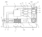
- the schematic block diagram which shows the inside of the air conditioner which concerns on embodiment.
- the schematic perspective view which expands and shows the wind direction change means of FIG.
- the conceptual diagram which shows the detection range of the infrared sensor of the air conditioner which concerns on embodiment.
- the flowchart which shows operation
- FIG. 1 is an external perspective view showing an air conditioner according to an embodiment.
- Drawing 2 is a schematic structure figure showing the inside of the air harmony machine concerning an embodiment.
- FIG. 3 is a schematic perspective view showing the wind direction changing means of FIG. 1 in an enlarged manner.
- Drawing 4 is a key map showing the detection range of the infrared sensor of the air harmony machine concerning an embodiment.
- the air conditioner includes an air conditioner casing 100 configured to be capable of self-supporting, and a suction port 101 for taking in indoor air A into the air conditioner casing 100.
- the water storage tank 102 stores water removed from the air taken into the suction port 101, and the exhaust port 103 discharges the dry air B from which water has been removed from the air conditioner housing 100 to the room. .
- the exhaust port 103 is provided with a wind direction varying means 1 capable of varying the wind direction of the dry air B.
- the wind direction varying means 1 is composed of a vertical louver 1a that varies the wind direction in the vertical direction and a horizontal louver 1b that varies the wind direction in the horizontal direction.
- the water storage tank 102 is detachably attached to the air conditioner housing 100.
- a blower fan that generates a series of airflows in which the indoor air A is sucked from the suction port 101 and the dry air B is discharged from the exhaust port 103 inside the air conditioner housing 1.
- a fan motor 2 a that rotates the blower fan 2
- a temperature sensor 3 temperature detection means
- a humidity sensor 4 that detects the humidity of the room air A (Humidity detecting means)
- dehumidifying means 5 for generating dry air B by removing moisture contained in room air A
- vertical variable motor 1c for changing vertical louver 1a in the vertical direction
- horizontal louver 1b A laterally variable motor 1d that changes the horizontal direction
- an infrared sensor 6 that is a surface temperature detecting means
- a display unit not shown
- a control circuit 7 control means
- control circuit 7 various sensors are connected to the control circuit 7 so that detection signals can be input to the control circuit 7. Further, the dehumidifying means 5, the display unit, and various motors are connected to the control circuit 7 so as to be controllable by the control means based on user operation inputs and input values of various sensors.
- the dehumidifying means 5 only needs to be able to remove moisture in the air and condense it.
- a heat pump circuit is configured to condense moisture in the air in an evaporator.
- a desiccant method in which moisture in the air removed by the adsorbent is condensed by a heat exchanger.
- the water removed from the room air A by the dehumidifying means 5 is stored in the water storage tank 102 as condensed water C.
- the vertical louver 1 a has a rectangular opening extending in the width direction of the air conditioner casing 100, and is vertical with the rotation axis of the vertical variable motor 1 c described above as a substantially axis. It is configured to be variable in direction.
- the horizontal louvers 1b are arranged at equal intervals in the vertical louver 1a, and are pivotally supported so as to be variable in the horizontal direction on the side opposite to the opening of the vertical louver 1a. It is configured to work together.
- the infrared sensor 6 is attached to one surface of a substantially central lateral louver 1b disposed in the longitudinal louver 1a. As a result, the detection range of the surface temperature of the object to be dried by the infrared sensor 6 becomes substantially the same as the direction of the dry air B that is varied by the wind direction varying means 1. That is, the infrared sensor 6 can detect the surface temperature of the entire region within the range in which the wind direction varying means 1 can blow.
- an infrared sensor 6 using a thermoelectromotive force effect is used, and an infrared absorption film 6a that receives thermal radiation (infrared rays) emitted from the surface of a predetermined region and the temperature of the infrared absorption film 6a.
- a thermistor 6b for detecting see FIGS. 2 and 3.
- the infrared sensor 6 has a difference between the temperature of the heat-sensitive part of the infrared absorption film 6a that rises in temperature by absorbing thermal radiation (hot contact) and the temperature of the infrared absorption film 6a detected by the thermistor 6b (cold contact). Is converted into an electric signal such as a voltage and input to a control circuit 7 to be described later.
- the surface temperature of the predetermined region can be determined from the magnitude of this electrical signal.
- the entire scanning range 200 is a planar area that extends in the horizontal direction (horizontal direction) and the vertical direction (vertical direction). It becomes.
- the infrared sensor 6 is controlled so as to detect the surface temperature for each of the divided areas 201 divided into a plurality of areas in the entire scanning range 200 in the horizontal direction and the vertical direction. Thereby, a detailed temperature map can be created for a wide range of regions.
- the control circuit 7 detects that the dehumidifying mode is selected from the switch operation of the operation unit (not shown), the wind direction varying means 1 is set so that the indoor humidity becomes the optimum humidity. Is driven so that air can be blown from the exhaust port 103, the fan motor 2a is driven to rotate the blower fan 2, and the dehumidifying means 5 is driven. Further, the control circuit 7 drives the longitudinal direction variable motor 1c and the lateral direction variable motor 1d of the wind direction varying means 1 so that the air is blown in the direction of the desired area in the room.
- the indoor air A is taken into the air conditioner casing 100 from the suction port 101, and the indoor temperature and humidity are detected by the temperature sensor 3 and the humidity sensor 4, respectively, and then dehumidified by the dehumidifying means 5. It becomes dry air B and is blown out into the room from the exhaust port 103.
- control circuit 7 detects the start of the operation in the drying mode of the laundry to be dried, as described above, the control circuit 7 drives the air direction varying means 1 so that air can be blown from the exhaust port 103, and the fan motor 2a is turned on. The air blower fan 2 is driven to rotate, and the dehumidifying means 5 is driven. Thereafter, the control circuit 7 reads the indoor humidity from the indoor air A taken into the air conditioner casing 100 via the humidity sensor 4 and determines whether the humidity is higher than a predetermined humidity.
- the control circuit 7 controls the fan motor 2a and the wind direction varying means 1 so that the dehumidifying capacity of the dehumidifying means 5 is maximized until the indoor humidity reaches the predetermined humidity. And when the indoor humidity falls to the predetermined humidity by the control, the control circuit 7 specifies the arrangement range of the laundry using the infrared sensor 6, and the vertical direction variable motor so that the dry air B hits the range. 1c and the lateral variable motor 1d are controlled so that the louvers 1a and 1b are directed toward the laundry.
- the predetermined humidity is a humidity set in advance according to the room temperature, and is set in the control circuit 7 as data.
- FIG. 5 is a flowchart showing an operation in the drying mode of the air conditioner according to the embodiment.
- the operation of the “normal dehumidifying operation” has been described above and will be omitted.
- the control circuit 7 of the air conditioner detects that the clothes drying eco-drying mode has been selected and starts driving, it starts measuring the total driving time T1 from the start of driving (S0) and the wind direction varying means 1 Is driven to allow air to be blown from the exhaust port 103, and the fan motor 2a is driven to rotate the blower fan 2 to start blowing (S1). In this stage, the dehumidifying operation is not performed.
- the control circuit 7 causes the wet clothing to be lower than the ambient temperature due to the evaporation of moisture by receiving the air. By detecting the position where this temperature is low with the infrared sensor 6, the range where the clothes which are to-be-dried objects are located is detected (S2).
- the control circuit 7 starts a timer that measures a predetermined time A (time limit) for detecting the temperature RT and the humidity RH1 (S3). And the temperature RT and the humidity RH1 are detected by the temperature sensor 3 and the humidity sensor 4, respectively, from the indoor air A sucked into the air conditioner housing 100 from the suction port 101 by the blower fan 2 (S4).
- the predetermined time A is, for example, a reference time used for determining the blowing time Ts by calculation in consideration of the humidity condition and the temperature condition for determining the blowing time.
- the control circuit 7 reads the detected humidity RH1 of the indoor air A and compares it with a predetermined humidity.
- the predetermined humidity is when, for example, a high humidity of 80% or more is detected.
- the process proceeds to S6, and when the humidity RH1 is higher than the predetermined humidity, the process proceeds to S11 and the dehumidifying operation is started (S5).
- the control circuit 7 reads the detected temperature RT of the indoor air A and compares it with a predetermined temperature.
- the predetermined temperature is when, for example, a state of 15 ° C. or lower is detected.
- the process proceeds to S7, and when the temperature RT is lower than the predetermined temperature, the process proceeds to S11 to start the dehumidifying operation (S6).
- the state of the indoor air A in the case of shifting from S6 to S7 is a state where the humidity is low and the temperature is relatively high. Therefore, it can be said that the wet clothes are easily dried.
- the state which transfers to S11 in S5 and S6 is the conditions which cannot fully dry with ventilation. That is, it is a judgment for performing control so that the object to be dried does not become undried by directly shifting to the dehumidifying operation without performing the blowing operation.
- the control circuit 7 executes control to detect the maximum value RHM of the humidity within the predetermined time A, and proceeds to S8 ( S7).
- the control circuit 7 proceeds to S9, and when the maximum humidity value RHM is not detected, the control circuit 7 proceeds to S4 (S8).
- the detection method of the maximum humidity value RHM may be that the highest humidity among the humidity values RH1 detected within the predetermined time A may be the maximum humidity value RHM, and when the humidity RH1 changes from rising to falling.
- the humidity RHM may be the maximum humidity value RHM.
- the control circuit 7 calculates the remaining blowing time Ts based on the detected maximum value RHM of humidity, and proceeds to S10 (S9).
- the blowing time Ts is set longer as the maximum humidity value RHM is larger. Thereby, even if humidity is high, the time of a dehumidification operation can be shortened and the energy saving effect can be acquired more.
- the control circuit 7 continues the air blowing operation for the remaining air blowing time Ts set as described above, and then shifts to S11 and ends the operation of only air blowing (S10).
- the control circuit 7 starts the dehumidifying operation and proceeds to S11, operates the blower fan 2 and the dehumidifying means 5, starts measurement of the dehumidifying operation time T2 from the start of the dehumidifying operation, and then proceeds to S13 ( S12). Accordingly, the room air A is taken into the air conditioner casing 100 from the suction port 101 by the rotation of the blower fan 2, and the dry air B continues to be blown out from the exhaust port 103. At this time, the control circuit 7 reads the room temperature detected by the temperature sensor 3 and continues reading the room humidity detected by the humidity sensor 4.
- control circuit 7 determines whether or not the dehumidifying operation time T2 from the start of the dehumidifying operation has passed 30 minutes, and when the dehumidifying operation time T exceeds 30 minutes, the process proceeds to S14 (S13).
- the control circuit 7 determines whether or not the humidity RH1 of the indoor air A is 50% or less (S14). If the humidity RH1 of the room air A is 50% or less, the process proceeds to S15, and if the humidity RH1 of the room air A exceeds 50%, the process proceeds to S19. In S19, the control circuit 7 determines whether or not the total operation time T1 from the start of operation exceeds 12 hours, which is a predetermined operation time limit (limit time). If the dehumidifying operation time T does not exceed 12 hours, the process proceeds to S14, and if the dehumidifying operation time T exceeds 12 hours, the process proceeds to S21 and a forced termination process is performed.
- the control circuit 7 calculates the remaining time TL of the dehumidifying operation from the dehumidifying operation time T from the start of the dehumidifying operation and the room temperature RT (S15), then proceeds to S16 and displays the remaining time TL on the display unit, The process proceeds to S17.
- the control circuit 7 determines whether or not the humidity RH1 of the room air A is 50% or less (S17). When the humidity RH1 of the indoor air A is 50% or less, the process proceeds to S18, and after performing an additional dehumidifying operation, the operation is terminated. When the humidity RH1 of the indoor air A exceeds 50%, the process proceeds to S20.
- the control circuit 7 determines whether or not the total operation time T1 from the start of operation exceeds 12 hours, which is a predetermined operation time limit (limit time). If the dehumidifying operation time T does not exceed 12 hours, the process proceeds to S16, and if the dehumidifying operation time T exceeds 12 hours, the process proceeds to S21 and the forced termination process is performed.
- the operation is performed by combining only the air blowing operation before the dehumidifying operation. Therefore, it is possible to perform the drying operation of the clothes to be dried while suppressing power consumption. It becomes possible.
- the air blowing operation is performed in the first half of the clothes drying operation, and the dehumidifying operation is finished in the latter half of the operation. Thereby, power consumption can be suppressed compared with the clothes drying operation by normal dehumidification operation.
- the operation of stopping only the blowing and stopping the dehumidifying operation is performed.
- the object to be dried can be dried at the end of operation so that the object to be dried does not become undried.
- the time for the air blowing operation is determined based on the humidity of the room air, it is possible to perform efficient air flow control suitable for the situation of the humidity of the room air.
- 1 Wind direction varying means 1a Longitudinal louver, 1b Lateral louver, 1c Longitudinal variable motor, 1d Lateral variable motor, 2 Blower fan, 2a Fan motor, 3 Temperature sensor, 4 Humidity sensor, 5 Dehumidifying means, 6 Infrared sensor , 6a Infrared absorbing film, 6b Thermistor, 7 Control circuit, 100 Air conditioner housing, 101 Suction port, 102 Water storage tank, 103 Exhaust port, 200 Total scanning range, 201 Division area, A room air, B Dry air
Landscapes
- Engineering & Computer Science (AREA)
- Chemical & Material Sciences (AREA)
- General Engineering & Computer Science (AREA)
- Mechanical Engineering (AREA)
- Thermal Sciences (AREA)
- Analytical Chemistry (AREA)
- General Chemical & Material Sciences (AREA)
- Oil, Petroleum & Natural Gas (AREA)
- Chemical Kinetics & Catalysis (AREA)
- Physics & Mathematics (AREA)
- Combustion & Propulsion (AREA)
- Air Conditioning Control Device (AREA)
- Control Of Washing Machine And Dryer (AREA)
- Drying Of Gases (AREA)
Abstract
上記の課題を解決する為には、空気中に含まれる水分を除去するための除湿手段と、室内の空気を吸気し、前記除湿手段を通過させて得られた乾燥空気を室内に吹き出す送風手段と、室内の湿度を検出する湿度検出手段と、室内の温度を検出する温度検出手段と、温度検出手段及び前記湿度検出手段の検知結果に基づき、除湿手段と送風手段を制御する制御手段を備え、制御手段は、除湿手段を動作させて除湿運転を行う前に、送風手段のみを所定時間動作させて送風運転を行うに動作可能に空気調和機を構成すればよい。
Description
本発明は、室内の湿気を除湿する空気調和機であって、特に室内に干された被乾燥物である洗濯物を乾燥する機能を有する空気調和機に関する。
従来から、赤外線検出手段による温度検出結果と、温度検出手段による室内雰囲気温度検出結果を制御手段が比較することで、被乾燥物の吸収した水分蒸発による顕熱低下を認識し、被乾燥物の顕熱低下による室内温度より低い温度分布の所在を被乾燥物の配置範囲と判断する空気調和機がある(例えば、特許文献1)。
しかしながら、前述した従来の空気調和機において、検出した温度に基づいて除湿運転を制御するので、湿度が低く衣類が乾燥しやすい環境条件であっても、除湿動作を行い無駄な除湿運転を行ってしまうという課題があった。
本発明は、前述のような課題を解決する為になされたものであり、環境条件によって運転を制御し、省エネルギー性能を高めた空気調和機を提供することを目的とする。
上記の課題を解決する為には、空気中に含まれる水分を除去するための除湿手段と、室内の空気を吸気し、前記除湿手段を通過させて得られた乾燥空気を室内に吹き出す送風手段と、室内の湿度を検出する湿度検出手段と、室内の温度を検出する温度検出手段と、温度検出手段及び/又は前記湿度検出手段の検知結果に基づき、除湿手段と送風手段を制御する制御手段を備え、制御手段は、除湿手段を動作させて除湿運転を行う前に、送風手段のみを所定時間動作させて送風運転を行うに動作可能に空気調和機を構成すればよい。
本発明によれば、環境条件の検出結果によって、被乾燥物が送風を用いても乾く条件と判断した場合は、衣類乾燥運転の前半で送風運転を行い、運転後半時に除湿運転で仕上げる。これにより、通常の除湿運転による衣類乾燥運転と比較すると消費電力を抑えることができる。
また、送風では十分に乾燥できない条件と判断した場合は、送風運転を行わないで除湿運転に移行する制御を行うことで、環境条件によらず、被乾燥物が未乾燥とならないように運転終了時には被乾燥物を乾燥させることができる。
また、送風では十分に乾燥できない条件と判断した場合は、送風運転を行わないで除湿運転に移行する制御を行うことで、環境条件によらず、被乾燥物が未乾燥とならないように運転終了時には被乾燥物を乾燥させることができる。
以下、図面を参照して本発明の実施の形態について説明する。
図1は、実施の形態に係る空気調和機を示す外観斜視図。図2は、実施の形態に係る空気調和機の内部を示す概略構成図。図3は、図1の風向変更手段を拡大して示す概略斜視図。図4は、実施の形態に係る空気調和機の赤外線センサーの検出範囲を示す概念図である。
図1は、実施の形態に係る空気調和機を示す外観斜視図。図2は、実施の形態に係る空気調和機の内部を示す概略構成図。図3は、図1の風向変更手段を拡大して示す概略斜視図。図4は、実施の形態に係る空気調和機の赤外線センサーの検出範囲を示す概念図である。
図1に示すように、本実施の形態の空気調和機は、自立可能に構成された空気調和機筐体100と、空気調和機筐体100内に室内空気Aを取り込むための吸込口101と、吸込口101に取り込まれた空気から除去された水分を溜める貯水タンク102と、水分が除去された乾燥空気Bを空気調和機筐体100から室内へ排出する排気口103とで構成されている。
排気口103には、乾燥空気Bの風向を可変可能な風向可変手段1が設けられている。この風向可変手段1は、鉛直方向の風向を可変する縦方向ルーバー1aと、水平方向の風向を可変する横方向ルーバー1bとによって構成されている。
また、貯水タンク102は、空気調和機筐体100に着脱可能に取り付けられている。
また、貯水タンク102は、空気調和機筐体100に着脱可能に取り付けられている。
次に、図2に示すように、空気調和機筐体1の内部には、吸込口101から室内空気Aを吸い込んで排気口103から乾燥空気Bを排出するという一連の気流を発生させる送風ファン2と、送風ファン2を回転させるファンモーター2aと、吸込口101から吸引された室内空気Aの温度を検出する温度センサー3(温度検出手段)と、室内空気Aの湿度を検出する湿度センサー4(湿度検出手段)と、室内空気Aに含まれる水分を除去して乾燥空気Bを生成する除湿手段5と、縦方向ルーバー1aを鉛直方向に可変する縦方向可変モーター1cと、横方向ルーバー1bを水平方向に可変する横方向可変モーター1dと、表面温度検出手段である赤外線センサー6と、各種情報を表示する表示部(図示せず)と、制御回路7(制御手段)とが備えられている。
これらの各種センサーは、検知信号が制御回路7へ入力可能となるように、制御回路7に接続されている。また、除湿手段5や表示部や各種モーターは、使用者の操作入力や各種センサーの入力値に基づいて制御手段により制御可能となるように制御回路7に接続されている。
次に、除湿手段5は、空気中の水分を除去して凝縮させることができるものであれば良く、例えば、最も一般的なものとして、ヒートポンプ回路を構成し蒸発器において空気中の水分を凝縮させる方式や、吸着剤によって除去された空気中の水分を熱交換器で凝縮させるデシカント方式などが用いられている。
そして、除湿手段5によって室内空気Aから除去された水分は、凝縮水Cとして貯水タンク102に貯留される。
そして、除湿手段5によって室内空気Aから除去された水分は、凝縮水Cとして貯水タンク102に貯留される。
次に、図3に示すように、縦方向ルーバー1aは、空気調和機筐体100の幅方向に延びる長方形状の開口を有し、前述した縦方向可変モーター1cの回転軸をほぼ軸として鉛直方向に可変可能に構成されている。
横方向ルーバー1bは、縦方向ルーバー1a内に等間隔に配置され、縦方向ルーバー1aの開口の反対側の奧に水平方向に可変可能に軸支され、前述した横方向可変モーター1dの駆動に連動するように構成されている。
横方向ルーバー1bは、縦方向ルーバー1a内に等間隔に配置され、縦方向ルーバー1aの開口の反対側の奧に水平方向に可変可能に軸支され、前述した横方向可変モーター1dの駆動に連動するように構成されている。
赤外線センサー6は、縦方向ルーバー1a内に配置されたほぼ中央の横方向ルーバー1bの片面に取り付けられている。
これにより、赤外線センサー6による被乾燥物などの表面温度の検出範囲は、風向可変手段1によって可変される乾燥空気Bの方向とほぼ同一となる。つまり、赤外線センサー6は、風向可変手段1が送風可能な範囲内の全領域の表面温度を検出することができる。
これにより、赤外線センサー6による被乾燥物などの表面温度の検出範囲は、風向可変手段1によって可変される乾燥空気Bの方向とほぼ同一となる。つまり、赤外線センサー6は、風向可変手段1が送風可能な範囲内の全領域の表面温度を検出することができる。
次に、赤外線センサー6は、例えば、熱起電力効果を利用したものが用いられており、所定領域の表面から発せられる熱放射(赤外線)を受ける赤外線吸収膜6aと、赤外線吸収膜6aの温度を検出するサーミスタ6bとで構成されている(図2、図3参照)。
この赤外線センサー6は、熱放射を吸収することによって昇温する赤外線吸収膜6aの感熱部分の温度(温接点)と、サーミスタ6bによって検出される赤外線吸収膜6aの温度(冷接点)との差を電圧等の電気信号に変換し、後述する制御回路7に入力する。この電気信号の大きさから所定領域の表面温度を判別できる。
この赤外線センサー6は、熱放射を吸収することによって昇温する赤外線吸収膜6aの感熱部分の温度(温接点)と、サーミスタ6bによって検出される赤外線吸収膜6aの温度(冷接点)との差を電圧等の電気信号に変換し、後述する制御回路7に入力する。この電気信号の大きさから所定領域の表面温度を判別できる。
ここで、所定領域の表面温度の検出方法について図4を用いて説明する。
図4に示すように、赤外線センサー6が検出可能な全領域を全走査範囲200とした場合、全走査範囲200は、横方向(水平方向)、縦方向(鉛直方向)に拡がる面状の範囲となる。
この赤外線センサー6は、全走査範囲200を水平方向と鉛直方向に対して、複数に分割された分割エリア201毎に表面温度を検出するように制御される。これにより、広範囲の領域に対して詳細な温度マップを作成することができる。
図4に示すように、赤外線センサー6が検出可能な全領域を全走査範囲200とした場合、全走査範囲200は、横方向(水平方向)、縦方向(鉛直方向)に拡がる面状の範囲となる。
この赤外線センサー6は、全走査範囲200を水平方向と鉛直方向に対して、複数に分割された分割エリア201毎に表面温度を検出するように制御される。これにより、広範囲の領域に対して詳細な温度マップを作成することができる。
次に、前述した制御回路7は、操作部(図示せず)のスイッチ操作から除湿モードが選択されたことを検知した場合には、室内の湿度が最適湿度となるように、風向可変手段1を駆動して排気口103から送風可能にし、ファンモーター2aを駆動して送風ファン2を回転させ、除湿手段5を駆動する。
また、制御回路7は、室内の所望領域の方向に送風されるように、風向可変手段1の縦方向可変モーター1cと横方向可変モーター1dを駆動する。これにより、室内空気Aは、吸込口101から空気調和機筐体100内に取り込まれ、温度センサー3及び湿度センサー4によりそれぞれ室内の温度と湿度が検出された後、除湿手段5により除湿されて乾燥空気Bとなり、排気口103から室内に吹き出される。
また、制御回路7は、室内の所望領域の方向に送風されるように、風向可変手段1の縦方向可変モーター1cと横方向可変モーター1dを駆動する。これにより、室内空気Aは、吸込口101から空気調和機筐体100内に取り込まれ、温度センサー3及び湿度センサー4によりそれぞれ室内の温度と湿度が検出された後、除湿手段5により除湿されて乾燥空気Bとなり、排気口103から室内に吹き出される。
また、制御回路7は、被乾燥物である洗濯物の乾燥モードの運転開始を検知したときには、前述したように、風向可変手段1を駆動して排気口103から送風可能にし、ファンモーター2aを駆動して送風ファン2を回転させ、除湿手段5を駆動する。
その後、制御回路7は、空気調和機筐体100内に取り込まれた室内空気Aから室内の湿度を、湿度センサー4を介して読み込んで、その湿度が所定湿度より高いかどうかを判定する。
その後、制御回路7は、空気調和機筐体100内に取り込まれた室内空気Aから室内の湿度を、湿度センサー4を介して読み込んで、その湿度が所定湿度より高いかどうかを判定する。
制御回路7は、室内の湿度が所定湿度より高いときには、室内の湿度が所定湿度に達するまで除湿手段5の除湿能力が最大となるようにファンモーター2a及び風向可変手段1を制御する。
そして、制御回路7は、その制御により室内の湿度が所定湿度まで低下したときには、赤外線センサー6を用いて洗濯物の配置範囲を特定し、その範囲に乾燥空気Bが当たるように縦方向可変モーター1cと横方向可変モーター1dを制御し、各ルーバー1a、1bを洗濯物の方向に向ける。所定湿度は、予め室内の温度に応じて設定された湿度で、データとして制御回路7に設定されている。
そして、制御回路7は、その制御により室内の湿度が所定湿度まで低下したときには、赤外線センサー6を用いて洗濯物の配置範囲を特定し、その範囲に乾燥空気Bが当たるように縦方向可変モーター1cと横方向可変モーター1dを制御し、各ルーバー1a、1bを洗濯物の方向に向ける。所定湿度は、予め室内の温度に応じて設定された湿度で、データとして制御回路7に設定されている。
次に、環境条件の検出結果によって、除湿運転と送風のみの送風運転を組み合わせて被乾燥物の乾燥を行う、いわゆる「衣類乾燥エコ干しモード」が選択されたときの制御回路7及び各部の動作について図5を用いて説明する。
図5は実施の形態に係る空気調和機の乾燥モードのときの動作を示すフローチャートである。尚、「通常の除湿運転」の動作については、先に述べているので省略する。
図5は実施の形態に係る空気調和機の乾燥モードのときの動作を示すフローチャートである。尚、「通常の除湿運転」の動作については、先に述べているので省略する。
空気調和機の制御回路7は、衣類乾燥エコ干しモードが選択されたことを検知し、運転を開始すると、運転開始からの総運転時間T1の測定を開始する(S0)と共に、風向可変手段1を駆動して排気口103から送風可能にし、ファンモーター2aを駆動して送風ファン2を回転させて送風を開始する(S1)。尚、この段階では、除湿運転は行っていない。
この時に制御回路7は、濡れた衣類は、送風を受けることにより水分が気化することにより周囲の温度より低くなる。この温度が低い位置を赤外線センサー6で検知することにより、被乾燥物である衣類が位置する範囲を検知する(S2)。
この時に制御回路7は、濡れた衣類は、送風を受けることにより水分が気化することにより周囲の温度より低くなる。この温度が低い位置を赤外線センサー6で検知することにより、被乾燥物である衣類が位置する範囲を検知する(S2)。
次に、室内空気Aの温度RTと湿度RH1を測定する工程に入る。
まず、制御回路7は、温度RTと湿度RH1を検知するための所定時間A(制限時間)を計測するタイマーをスタートさせる(S3)。そして、送風ファン2により吸込口101から空気調和機筐体100内部へ吸引された室内空気Aを、温度センサー3と湿度センサー4により、それぞれ温度RTと湿度RH1を検知する(S4)。
所定時間Aとは、たとえば送風時間決めるための、湿度条件・温度条件を加味した計算による送風時間Ts決定のために用いる基準の時間となるものである。
まず、制御回路7は、温度RTと湿度RH1を検知するための所定時間A(制限時間)を計測するタイマーをスタートさせる(S3)。そして、送風ファン2により吸込口101から空気調和機筐体100内部へ吸引された室内空気Aを、温度センサー3と湿度センサー4により、それぞれ温度RTと湿度RH1を検知する(S4)。
所定時間Aとは、たとえば送風時間決めるための、湿度条件・温度条件を加味した計算による送風時間Ts決定のために用いる基準の時間となるものである。
次に制御回路7は、検知した室内空気Aの湿度RH1を読み込み、所定湿度と比較する。所定湿度は、たとえば80%以上の湿度が高い状態を検知したときである。
湿度RH1が所定湿度より低い場合はS6に移行し、湿度RH1が所定の湿度より高い場合はS11に移行して除湿運転を開始する(S5)。
次に制御回路7は、検知した室内空気Aの温度RTを読み込み、所定温度と比較する。
所定温度は、たとえば15℃以下となる状態を検知したときである。
温度RTが所定温度より高い場合はS7に移行し、温度RTが所定の温度より低い場合はS11に移行して除湿運転を開始する(S6)。
湿度RH1が所定湿度より低い場合はS6に移行し、湿度RH1が所定の湿度より高い場合はS11に移行して除湿運転を開始する(S5)。
次に制御回路7は、検知した室内空気Aの温度RTを読み込み、所定温度と比較する。
所定温度は、たとえば15℃以下となる状態を検知したときである。
温度RTが所定温度より高い場合はS7に移行し、温度RTが所定の温度より低い場合はS11に移行して除湿運転を開始する(S6)。
このS6からS7に移行する場合の室内空気Aの状態は、比較的、湿度も低く温度も高い状態であることから、濡れた衣類が乾燥しやすい状態といえる。
また、S5及びS6においてS11に移行する状態は、送風では十分に乾燥できない条件である。つまり、送風運転を行わず、直接除湿運転に移行し被乾燥物が未乾燥とならないように制御を行うための判断である。
また、S5及びS6においてS11に移行する状態は、送風では十分に乾燥できない条件である。つまり、送風運転を行わず、直接除湿運転に移行し被乾燥物が未乾燥とならないように制御を行うための判断である。
次に制御回路7は、湿度RH1が所定湿度より低く、かつ、温度RTが所定温度より高い場合は、所定時間A内の湿度の最大値RHMを検出する制御を実行し、S8へ移行する(S7)。そして制御回路7は、所定時間A内の湿度の最大値RHMを検出した場合はS9へ移行し、湿度の最大値RHMを検出していない場合はS4に移行する(S8)。
ここで湿度の最大値RHMの検出方法は、所定時間A内で検知した湿度RH1の内、最も大きい湿度を湿度の最大値RHMとしてもよく、また、湿度RH1が上昇から下降に転じたときの湿度RHMを湿度の最大値RHMとしてもよい。
ここで湿度の最大値RHMの検出方法は、所定時間A内で検知した湿度RH1の内、最も大きい湿度を湿度の最大値RHMとしてもよく、また、湿度RH1が上昇から下降に転じたときの湿度RHMを湿度の最大値RHMとしてもよい。
次に制御回路7は、検出した湿度の最大値RHMに基づき、残りの送風時間Tsの計算を行いS10に移行する(S9)。ここで送風時間Tsは、湿度の最大値RHMが大きいほど、長く時間設定される。これにより、湿度が高くても除湿運転の時間を短くすることができ、より省エネ効果を得られる。
そして、制御回路7は、上記のように設定された残りの送風時間Tsの間、送風運転を続けた後、S11へ移行し送風のみの運転を終了する(S10)。
そして、制御回路7は、上記のように設定された残りの送風時間Tsの間、送風運転を続けた後、S11へ移行し送風のみの運転を終了する(S10)。
次に制御回路7は、除湿運転を開始してS11に移行し、送風ファン2と除湿手段5を動作させ、除湿運転開始からの除湿運転時間T2の計測を開始して、S13に移行する(S12)。
これにより、送風ファン2の回転により室内空気Aが吸い込み口101から空気調和機筐体100内に取り込まれ、排気口103から乾燥空気Bが吹き出され続ける。この時、制御回路7は、温度センサー3により検出された室内の温度を読み込み、湿度センサー4により検出された室内の湿度を読み込み続ける。
これにより、送風ファン2の回転により室内空気Aが吸い込み口101から空気調和機筐体100内に取り込まれ、排気口103から乾燥空気Bが吹き出され続ける。この時、制御回路7は、温度センサー3により検出された室内の温度を読み込み、湿度センサー4により検出された室内の湿度を読み込み続ける。
次に制御回路7は、除湿運転開始からの除湿運転時間T2が30分を経過したか否かを判定し、除湿運転時間Tが30分を越える場合にはS14に移行する(S13)。
次に制御回路7は、室内空気Aの湿度RH1が50%以下であるか否かを判定する(S14)。室内空気Aの湿度RH1が50%以下である場合はS15に移行し、室内空気Aの湿度RH1が50%を超えている場合はS19に移行する。
そして制御回路7は、S19において、運転開始からの総運転時間T1が、予め定めた運転の制限時間(リミット時間)である12時間を越えるか否かを判定する。除湿運転時間Tが12時間を越えない場合は、S14に移行し、除湿運転時間Tが12時間を越える場合は、S21に移行して強制終了処理が行われる。
そして制御回路7は、S19において、運転開始からの総運転時間T1が、予め定めた運転の制限時間(リミット時間)である12時間を越えるか否かを判定する。除湿運転時間Tが12時間を越えない場合は、S14に移行し、除湿運転時間Tが12時間を越える場合は、S21に移行して強制終了処理が行われる。
次に制御回路7は、除湿運転の残り時間TLを除湿運転開始からの除湿運転時間Tと室温RTより算出(S15)した後、S16に移行して表示部に残り時間TLを表示して、S17に移行する。
次に制御回路7は、室内空気Aの湿度RH1が50%以下であるか否かを判定する(S17)。室内空気Aの湿度RH1が50%以下である場合はS18に移行して、追加の除湿運転を行った後、運転を終了する。室内空気Aの湿度RH1が50%を超えている場合はS20に移行する。
そして、制御回路7は、S20において、運転開始からの総運転時間T1が、予め定めた運転の制限時間(リミット時間)である12時間を越えるか否かを判定する。除湿運転時間Tが12時間を越えない場合は、S16に移行し、除湿運転時間Tが12時間を越える場合は、S21に移行して強制終了処理が行われる。
次に制御回路7は、室内空気Aの湿度RH1が50%以下であるか否かを判定する(S17)。室内空気Aの湿度RH1が50%以下である場合はS18に移行して、追加の除湿運転を行った後、運転を終了する。室内空気Aの湿度RH1が50%を超えている場合はS20に移行する。
そして、制御回路7は、S20において、運転開始からの総運転時間T1が、予め定めた運転の制限時間(リミット時間)である12時間を越えるか否かを判定する。除湿運転時間Tが12時間を越えない場合は、S16に移行し、除湿運転時間Tが12時間を越える場合は、S21に移行して強制終了処理が行われる。
以上のように制御回路7により各部を動作させることで、除湿運転の前に送風のみの送風運転を組み合わせて運転するので、消費電力を抑えて被乾燥物である衣類の乾燥運転を行うことが可能となる。
特に、環境条件の検出結果によって、被乾燥物が送風を用いても乾く条件と判断した場合は、衣類乾燥運転の前半で送風運転を行い、運転後半時に除湿運転で仕上げる。これにより、通常の除湿運転による衣類乾燥運転と比較すると消費電力を抑えることができる。
特に、環境条件の検出結果によって、被乾燥物が送風を用いても乾く条件と判断した場合は、衣類乾燥運転の前半で送風運転を行い、運転後半時に除湿運転で仕上げる。これにより、通常の除湿運転による衣類乾燥運転と比較すると消費電力を抑えることができる。
また、室内空気の温度や湿度を検知して、送風では十分に乾燥できない条件と判断した場合(S5、S6)は、送風のみの運転を中止して除湿運転に移行する制御を行うので、環境条件によらず、被乾燥物が未乾燥とならないように運転終了時には被乾燥物を乾燥させることができる。
また、室内空気の湿度に基づき送風運転の時間を決定するので、室内空気の湿度の状況に適合した効率のよい送風制御を行うことが可能となる。
また、室内空気の湿度に基づき送風運転の時間を決定するので、室内空気の湿度の状況に適合した効率のよい送風制御を行うことが可能となる。
以上の実施の形態にて用いた制御の基準となる数値は一例であり、本発明は前述の数値に限ったものではない。また、これらの基準となる数値は、空気調和機を使用する環境や使用者の好みに応じて、適宜設定変更を可能に構成しても良い。
1 風向可変手段、1a 縦方向ルーバー、1b 横方向ルーバー、1c 縦方向可変モーター、1d 横方向可変モーター、2 送風ファン、2a ファンモーター、3 温度センサー、4 湿度センサー、5 除湿手段、6 赤外線センサー、6a 赤外線吸収膜、6b サーミスタ、7 制御回路、100 空気調和機筐体、101 吸込口、102 貯水タンク、103 排気口、200 全走査範囲、201 分割エリア、A 室内空気、B 乾燥空気。
Claims (4)
- 空気中に含まれる水分を除去するための除湿手段と、
室内の空気を吸気し、前記除湿手段を通過させて得られた乾燥空気を室内に吹き出す送風手段と、
室内の湿度を検出する湿度検出手段と、
室内の温度を検出する温度検出手段と、
前記温度検出手段又は前記湿度検出手段の検知結果に基づき、前記除湿手段と前記送風手段を制御する制御手段を備え、
前記制御手段は、前記除湿手段を動作させて除湿運転を行う前に、前記送風手段のみを所定時間動作させて送風運転を行うことを特徴とする空気調和機。 - 前記制御手段は、前記送風運転を行なうと共に、前記湿度検出手段により検知された室内空気の検知湿度が所定湿度より低いか否かを判定し、室内空気の湿度が所定湿度より高い場合には、直ちに除湿運転を開始することを特徴とする請求項1記載の空気調和機。
- 前記制御手段は、前記送風運転を行なうと共に、前記温度検出手段により検知された室内空気の検知温度が所定温度より低いか否かを判定し、室内空気の温度が所定温度より低い場合には、直ちに除湿運転を開始することを特徴とする請求項1記載の空気調和機。
- 前記制御手段は、室内空気の湿度に基づき前記送風運転の時間を決定することを特徴とする請求項1乃至3に記載の空気調和機。
Priority Applications (4)
| Application Number | Priority Date | Filing Date | Title |
|---|---|---|---|
| HK14100949.6A HK1187975B (en) | 2011-03-07 | 2012-02-10 | Air conditioner |
| NZ613995A NZ613995B2 (en) | 2011-03-07 | 2012-02-10 | Air-conditioning apparatus |
| JP2013503354A JPWO2012120786A1 (ja) | 2011-03-07 | 2012-02-10 | 空気調和機 |
| CN201280011966.4A CN103443555B (zh) | 2011-03-07 | 2012-02-10 | 空气调节机 |
Applications Claiming Priority (2)
| Application Number | Priority Date | Filing Date | Title |
|---|---|---|---|
| JP2011-048962 | 2011-03-07 | ||
| JP2011048962 | 2011-03-07 |
Publications (1)
| Publication Number | Publication Date |
|---|---|
| WO2012120786A1 true WO2012120786A1 (ja) | 2012-09-13 |
Family
ID=46797763
Family Applications (1)
| Application Number | Title | Priority Date | Filing Date |
|---|---|---|---|
| PCT/JP2012/000897 Ceased WO2012120786A1 (ja) | 2011-03-07 | 2012-02-10 | 空気調和機 |
Country Status (4)
| Country | Link |
|---|---|
| JP (2) | JPWO2012120786A1 (ja) |
| CN (1) | CN103443555B (ja) |
| TW (1) | TWI456148B (ja) |
| WO (1) | WO2012120786A1 (ja) |
Cited By (5)
| Publication number | Priority date | Publication date | Assignee | Title |
|---|---|---|---|---|
| JP2015108497A (ja) * | 2013-10-21 | 2015-06-11 | アイリスオーヤマ株式会社 | 衣類乾燥除湿機 |
| EP2966216A4 (en) * | 2013-03-05 | 2016-09-28 | Mitsubishi Electric Corp | DRY |
| JP2018036009A (ja) * | 2016-09-01 | 2018-03-08 | 日立ジョンソンコントロールズ空調株式会社 | 空気調和機 |
| JPWO2018154808A1 (ja) * | 2017-02-22 | 2019-08-08 | 三菱電機株式会社 | 除湿機 |
| WO2019181007A1 (ja) * | 2018-03-19 | 2019-09-26 | シャープ株式会社 | 空気調和装置、空気調和方法および空気調和プログラム |
Families Citing this family (5)
| Publication number | Priority date | Publication date | Assignee | Title |
|---|---|---|---|---|
| JP6696515B2 (ja) * | 2016-02-16 | 2020-05-20 | 三菱電機株式会社 | 除湿機 |
| CN107849797B (zh) * | 2016-05-18 | 2019-11-26 | 友隆电器工业(深圳)有限公司 | 干衣机的烘干控制方法及系统 |
| CN107869826B (zh) * | 2017-11-29 | 2019-08-30 | 广东美的制冷设备有限公司 | 空调器及其控制方法和装置 |
| CN112066659A (zh) * | 2020-09-15 | 2020-12-11 | 湖南兴业太阳能科技有限公司 | 一种空气能热泵烘干机的循环排湿控制系统及控制方法 |
| CN115127332B (zh) * | 2022-06-13 | 2023-12-19 | 青岛海尔空调器有限总公司 | 烘干机排出气体处理系统及方法 |
Citations (7)
| Publication number | Priority date | Publication date | Assignee | Title |
|---|---|---|---|---|
| JPH0712386A (ja) * | 1993-06-24 | 1995-01-17 | Toshiba Corp | 空気調和機の乾燥運転方法 |
| JPH08126810A (ja) * | 1994-10-31 | 1996-05-21 | Sanyo Electric Co Ltd | 除湿乾燥装置 |
| JP2001141284A (ja) * | 1999-11-15 | 2001-05-25 | Matsushita Seiko Co Ltd | 除湿機 |
| JP2001259350A (ja) * | 2000-03-17 | 2001-09-25 | Sharp Corp | 除湿機 |
| JP2006150306A (ja) * | 2004-12-01 | 2006-06-15 | Matsushita Electric Ind Co Ltd | 除湿装置 |
| JP2009287813A (ja) * | 2008-05-28 | 2009-12-10 | Sharp Corp | 空気調和機 |
| JP2010185597A (ja) * | 2009-02-10 | 2010-08-26 | Mitsubishi Electric Corp | 除湿機 |
Family Cites Families (8)
| Publication number | Priority date | Publication date | Assignee | Title |
|---|---|---|---|---|
| JPS63132231U (ja) * | 1988-01-22 | 1988-08-30 | ||
| JP2889723B2 (ja) * | 1991-04-16 | 1999-05-10 | 三洋電機株式会社 | 寝具等の乾燥機 |
| JP2693328B2 (ja) * | 1991-10-04 | 1997-12-24 | 株式会社日立製作所 | 空調機 |
| JP3619547B2 (ja) * | 1994-09-16 | 2005-02-09 | 株式会社日立製作所 | 空気調和機 |
| JP2004226050A (ja) * | 2003-01-27 | 2004-08-12 | Lg Electronics Inc | 空調機器 |
| JP4915111B2 (ja) * | 2006-03-10 | 2012-04-11 | パナソニック株式会社 | 除湿機 |
| JP2008023486A (ja) * | 2006-07-24 | 2008-02-07 | Toshiba Home Technology Corp | 除湿機 |
| JP2009219582A (ja) * | 2008-03-14 | 2009-10-01 | Panasonic Corp | 除湿装置 |
-
2012
- 2012-02-10 CN CN201280011966.4A patent/CN103443555B/zh not_active Expired - Fee Related
- 2012-02-10 WO PCT/JP2012/000897 patent/WO2012120786A1/ja not_active Ceased
- 2012-02-10 JP JP2013503354A patent/JPWO2012120786A1/ja active Pending
- 2012-02-22 TW TW101105788A patent/TWI456148B/zh not_active IP Right Cessation
-
2015
- 2015-03-26 JP JP2015064807A patent/JP6104303B2/ja not_active Expired - Fee Related
Patent Citations (7)
| Publication number | Priority date | Publication date | Assignee | Title |
|---|---|---|---|---|
| JPH0712386A (ja) * | 1993-06-24 | 1995-01-17 | Toshiba Corp | 空気調和機の乾燥運転方法 |
| JPH08126810A (ja) * | 1994-10-31 | 1996-05-21 | Sanyo Electric Co Ltd | 除湿乾燥装置 |
| JP2001141284A (ja) * | 1999-11-15 | 2001-05-25 | Matsushita Seiko Co Ltd | 除湿機 |
| JP2001259350A (ja) * | 2000-03-17 | 2001-09-25 | Sharp Corp | 除湿機 |
| JP2006150306A (ja) * | 2004-12-01 | 2006-06-15 | Matsushita Electric Ind Co Ltd | 除湿装置 |
| JP2009287813A (ja) * | 2008-05-28 | 2009-12-10 | Sharp Corp | 空気調和機 |
| JP2010185597A (ja) * | 2009-02-10 | 2010-08-26 | Mitsubishi Electric Corp | 除湿機 |
Cited By (7)
| Publication number | Priority date | Publication date | Assignee | Title |
|---|---|---|---|---|
| EP2966216A4 (en) * | 2013-03-05 | 2016-09-28 | Mitsubishi Electric Corp | DRY |
| JP2015108497A (ja) * | 2013-10-21 | 2015-06-11 | アイリスオーヤマ株式会社 | 衣類乾燥除湿機 |
| JP2018036009A (ja) * | 2016-09-01 | 2018-03-08 | 日立ジョンソンコントロールズ空調株式会社 | 空気調和機 |
| JPWO2018154808A1 (ja) * | 2017-02-22 | 2019-08-08 | 三菱電機株式会社 | 除湿機 |
| WO2019181007A1 (ja) * | 2018-03-19 | 2019-09-26 | シャープ株式会社 | 空気調和装置、空気調和方法および空気調和プログラム |
| CN112219070A (zh) * | 2018-03-19 | 2021-01-12 | 夏普株式会社 | 空气调节装置、空气调节方法以及空气调节程序 |
| JPWO2019181007A1 (ja) * | 2018-03-19 | 2021-03-11 | シャープ株式会社 | 空気調和装置、空気調和方法および空気調和プログラム |
Also Published As
| Publication number | Publication date |
|---|---|
| CN103443555A (zh) | 2013-12-11 |
| CN103443555B (zh) | 2016-04-13 |
| TWI456148B (zh) | 2014-10-11 |
| JP6104303B2 (ja) | 2017-03-29 |
| JP2015158353A (ja) | 2015-09-03 |
| NZ613995A (en) | 2014-11-28 |
| JPWO2012120786A1 (ja) | 2014-07-07 |
| HK1187975A1 (zh) | 2014-04-17 |
| TW201303231A (zh) | 2013-01-16 |
Similar Documents
| Publication | Publication Date | Title |
|---|---|---|
| JP6104303B2 (ja) | 空気調和機 | |
| JP5984666B2 (ja) | 除湿機 | |
| JP5843001B2 (ja) | 除湿機 | |
| JP6037007B2 (ja) | 除湿機 | |
| JP5904272B2 (ja) | 空気調和機 | |
| WO2013145944A1 (ja) | 空気調和機 | |
| JP5999255B2 (ja) | 除湿機 | |
| EP2545979B1 (en) | Dehumidifier | |
| JP5839113B2 (ja) | 空気調和機 | |
| JP5999250B2 (ja) | 除湿機 | |
| JP5610797B2 (ja) | 除湿機 | |
| NZ613995B2 (en) | Air-conditioning apparatus | |
| HK1187975B (en) | Air conditioner | |
| HK1200509B (en) | Air conditioner |
Legal Events
| Date | Code | Title | Description |
|---|---|---|---|
| 121 | Ep: the epo has been informed by wipo that ep was designated in this application |
Ref document number: 12754590 Country of ref document: EP Kind code of ref document: A1 |
|
| ENP | Entry into the national phase |
Ref document number: 2013503354 Country of ref document: JP Kind code of ref document: A |
|
| NENP | Non-entry into the national phase |
Ref country code: DE |
|
| 122 | Ep: pct application non-entry in european phase |
Ref document number: 12754590 Country of ref document: EP Kind code of ref document: A1 |