WO2012120603A1 - 車両の空調装置 - Google Patents
車両の空調装置 Download PDFInfo
- Publication number
- WO2012120603A1 WO2012120603A1 PCT/JP2011/055132 JP2011055132W WO2012120603A1 WO 2012120603 A1 WO2012120603 A1 WO 2012120603A1 JP 2011055132 W JP2011055132 W JP 2011055132W WO 2012120603 A1 WO2012120603 A1 WO 2012120603A1
- Authority
- WO
- WIPO (PCT)
- Prior art keywords
- cooling water
- heating
- passenger compartment
- peltier element
- vehicle
- Prior art date
Links
Images


Classifications
-
- F—MECHANICAL ENGINEERING; LIGHTING; HEATING; WEAPONS; BLASTING
- F25—REFRIGERATION OR COOLING; COMBINED HEATING AND REFRIGERATION SYSTEMS; HEAT PUMP SYSTEMS; MANUFACTURE OR STORAGE OF ICE; LIQUEFACTION SOLIDIFICATION OF GASES
- F25B—REFRIGERATION MACHINES, PLANTS OR SYSTEMS; COMBINED HEATING AND REFRIGERATION SYSTEMS; HEAT PUMP SYSTEMS
- F25B21/00—Machines, plants or systems, using electric or magnetic effects
- F25B21/02—Machines, plants or systems, using electric or magnetic effects using Peltier effect; using Nernst-Ettinghausen effect
-
- B—PERFORMING OPERATIONS; TRANSPORTING
- B60—VEHICLES IN GENERAL
- B60H—ARRANGEMENTS OF HEATING, COOLING, VENTILATING OR OTHER AIR-TREATING DEVICES SPECIALLY ADAPTED FOR PASSENGER OR GOODS SPACES OF VEHICLES
- B60H1/00—Heating, cooling or ventilating [HVAC] devices
- B60H1/00357—Air-conditioning arrangements specially adapted for particular vehicles
- B60H1/00385—Air-conditioning arrangements specially adapted for particular vehicles for vehicles having an electrical drive, e.g. hybrid or fuel cell
- B60H1/004—Air-conditioning arrangements specially adapted for particular vehicles for vehicles having an electrical drive, e.g. hybrid or fuel cell for vehicles having a combustion engine and electric drive means, e.g. hybrid electric vehicles
-
- B—PERFORMING OPERATIONS; TRANSPORTING
- B60—VEHICLES IN GENERAL
- B60H—ARRANGEMENTS OF HEATING, COOLING, VENTILATING OR OTHER AIR-TREATING DEVICES SPECIALLY ADAPTED FOR PASSENGER OR GOODS SPACES OF VEHICLES
- B60H1/00—Heating, cooling or ventilating [HVAC] devices
- B60H1/00478—Air-conditioning devices using the Peltier effect
-
- B—PERFORMING OPERATIONS; TRANSPORTING
- B60—VEHICLES IN GENERAL
- B60H—ARRANGEMENTS OF HEATING, COOLING, VENTILATING OR OTHER AIR-TREATING DEVICES SPECIALLY ADAPTED FOR PASSENGER OR GOODS SPACES OF VEHICLES
- B60H1/00—Heating, cooling or ventilating [HVAC] devices
- B60H1/00642—Control systems or circuits; Control members or indication devices for heating, cooling or ventilating devices
- B60H1/00814—Control systems or circuits characterised by their output, for controlling particular components of the heating, cooling or ventilating installation
- B60H1/00878—Control systems or circuits characterised by their output, for controlling particular components of the heating, cooling or ventilating installation the components being temperature regulating devices
- B60H1/00899—Controlling the flow of liquid in a heat pump system
Definitions
- the present invention relates to a vehicle air conditioner.
- the temperature in the passenger compartment is adjusted by cooling the air sent to the passenger compartment with a cooler or heating the air using the heat of the internal combustion engine. It was like that.
- an increasing number of vehicles are difficult to use the internal combustion engine as a heat source for air conditioning (temperature adjustment) of the passenger compartment.
- Such vehicles include, for example, an electric vehicle that is not equipped with an internal combustion engine as a prime mover but is equipped with only a motor, and a hybrid vehicle that is equipped with a motor and an internal combustion engine as prime movers and frequently stops operation of the engine. .
- the Peltier element includes a cooling unit that absorbs heat and a heating unit that dissipates heat, and the cooling unit and the heat dissipating unit can be switched by reversing the polarity of the electrodes. And when cooling with an air conditioner in order to reduce the temperature of a vehicle interior, the air sent to the vehicle interior is cooled by the cooling part of a Peltier device. On the other hand, when heating by the air conditioner to raise the temperature of the passenger compartment, the polarity of the electrode in the Peltier element is reversed from the case of the above cooling, so that the air sent to the passenger compartment is heated by the heating part of the Peltier element. Heated.
- the passenger compartment air conditioning Heating
- the structure of the apparatus is different from that of a conventional air conditioner in which the air sent to the passenger compartment is cooled by a cooler or heated using the heat of the internal combustion engine. A big change is inevitable. If the structure of the air conditioner changes drastically in this way, conventional equipment or the like cannot be used in manufacturing the apparatus, and equipment or the like for manufacturing the apparatus must be renewed. As a result, there is a problem that the cost for manufacturing the air conditioner is increased because the equipment for manufacturing must be renewed.
- an internal combustion engine is used as a heat source for air-conditioning the passenger compartment while using a conventional air-conditioner that cools the air sent to the passenger compartment with a cooler or heats the internal combustion engine. It is desired to be able to perform air conditioning (heating) of a passenger compartment in a vehicle in which it is difficult to use an engine.
- the present invention has been made in view of such a situation, and the object thereof is to change the structure of a vehicle in which it is difficult to use an internal combustion engine as a heat source for air conditioning a passenger compartment.
- An object of the present invention is to provide a vehicle air conditioner capable of air conditioning a passenger compartment.
- the vehicle air conditioner when the air sent to the vehicle compartment is cooled or heated to adjust the temperature of the vehicle compartment, the air is cooled by the cooler.
- the air is heated by a Peltier element.
- a Peltier element since the thing provided in the conventional air conditioner can be utilized as said cooler, it can avoid that the structure of an air conditioner changes significantly.
- air sent to the passenger compartment can be heated by a Peltier element. ) Can be performed. Therefore, in a vehicle in which it is difficult to use an internal combustion engine as a heat source for air conditioning the passenger compartment, the passenger compartment can be air-conditioned without significantly changing the structure.
- the circulation circuit which circulates the cooling water heat-exchanged with the internal combustion engine mounted in a vehicle was provided, and the air sent to a vehicle interior by the cooling water was performed. Therefore, in a vehicle equipped with an internal combustion engine, as a method of heating the air sent to the passenger compartment by the Peltier element, the cooling water of the circulation circuit is heated by the heating part of the Peltier element, and the air is supplied through the cooling water. It is possible to adopt a method of heating. In this case, heating by the Peltier element of the air sent to the passenger compartment can be realized using the above-described circulation circuit provided in the conventional air conditioner. For this reason, it can avoid that the structure of an air conditioner changes significantly from the past. Further, when the internal combustion engine is operated to generate heat, the heat can be recovered by cooling water circulating in the circulation circuit and used for air conditioning (heating) of the passenger compartment.
- the circulation circuit includes a first path that realizes passage of the cooling water circulating through the internal combustion engine and a second path that bypasses the cooling water internal combustion engine.
- One of the first path and the second path is used as a path for circulating the cooling water.
- the second path is selected when the internal combustion engine generates a small amount of heat, while the first path is selected when the internal combustion engine generates a large amount of heat. Is possible.
- the second path is selected as described above as the path for circulating the cooling water in the circulation circuit, the heat of the cooling water heated by the Peltier element heating unit is caused by the internal combustion engine.
- the cooling water can be effectively heated by the heating part of the Peltier element. Further, when the internal combustion engine generates a lot of heat, if the first path is selected as described above as the path for circulating the cooling water in the circulation circuit, the cooling water can be heated by the internal combustion engine. The heating of the cooling water by the heating part can be stopped, or the amount of heat during the heating can be reduced.
- the circulation circuit is a radiator that causes the cooling water to flow and exchange heat between the cooling water and outside air when the temperature of the cooling water circulating therethrough is equal to or higher than a predetermined determination value.
- the Peltier element includes a cooling unit that exchanges heat with the cooling water circulating in the cooling water circuit.
- a cooling water circuit guides the cooling water which circulates there to the radiator of the above-mentioned circulation circuit, and performs heat exchange with the cooling water and outside air with the radiator.
- the temperature of the cooling water in the cooling water circuit becomes excessively low due to such heat exchange, and as a result, the temperature of the cooling part of the Peltier element that exchanges heat with the cooling water is also suppressed from excessively decreasing.
- the Peltier element when the Peltier element is heated by the heating unit, heat is transferred from the cooling unit to the heating unit.
- the smaller the temperature difference between the cooling unit and the heating unit the more efficiently the heat transfer from the cooling unit to the heating unit, in other words, the heating by the heating unit.
- the temperature difference between the heating part and the cooling part of the Peltier element can be suppressed, and the heating by the heating part of the Peltier element is efficiently performed. be able to.
- the Peltier element includes a cooling unit that exchanges heat with cooling water that circulates in the cooling water circuit and cools the electrical equipment mounted on the vehicle.
- the Peltier element when the Peltier element is heated by the heating unit, heat is transferred from the cooling unit to the heating unit of the element, and thus the temperature is lowered in the cooling unit.
- the cooling water whose temperature has been lowered by heat exchange between the cooling part of the Peltier element and the cooling water of the cooling water circuit for cooling the electric device, the cooling can be effectively performed.
- the cooling water of a cooling water circuit receives the heat from the said electric equipment and it is suppressed that a temperature falls too much, it is suppressed that the cooling part of a Peltier device also falls too much.
- the cooling water circuit includes a heat exchanger that allows the cooling water circulating therethrough to exchange heat between the cooling water and the outside air.
- the path for circulating the coolant in the circulation circuit is switched to the second path and the Peltier element is heated.
- the control part which heats a part is provided. This controller switches the path for circulating the coolant in the circulation circuit to the first path and heats the Peltier element when heating the passenger compartment while the vehicle is running with the internal combustion engine in operation. Stop heating the part.
- the second path is selected as the path for circulating the cooling water in the circulation circuit as described above, thereby heating the Peltier element. The heat of the cooling water heated by the section is not taken away by the internal combustion engine.
- the effective cooling water heating by the heating part of a Peltier device can be performed.
- the cooling water is selected by selecting the first path as described above as the path for circulating the cooling water in the circulation circuit. Can be heated by the internal combustion engine without being heated by the heating part of the Peltier element. For this reason, the heating of the heating part of the Peltier element can be stopped, and thereby unnecessary driving of the Peltier element can be avoided.
- This hybrid vehicle is equipped with a motor generator and an internal combustion engine as a prime mover, and switches the prime mover to be used according to the running state and the running demand. Specifically, only the motor generator is used as a prime mover, only the internal combustion engine is used as a prime mover, or both the internal combustion engine and the motor generator are used as prime movers.
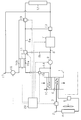
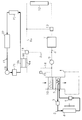
- Such a hybrid vehicle air conditioner is provided with a cooler 2 for cooling the air sent to the passenger compartment 1 as shown in FIG.
- the cooler 2 is a vapor compression heat pump.
- the cooler 2 includes a compressor 3 that compresses the refrigerant, a condenser 4 that cools the refrigerant that has been compressed by the compressor 3 and that has been heated by outside air, an expansion valve 5 that expands the refrigerant cooled by the condenser 4,
- An evaporator 6 is provided that exchanges heat between the refrigerant expanded by the expansion valve 5 and having its temperature lowered with the air sent to the passenger compartment 1.
- the said air conditioner when the compressor 3 of the cooler 2 is driven and the refrigerant is circulated, the low-temperature refrigerant passes through the evaporator 6 and the air sent to the passenger compartment 1 is cooled by the refrigerant.
- the air conditioner is provided with a circulation circuit 8 that circulates cooling water that exchanges heat with the internal combustion engine 7 and that heats the air sent to the passenger compartment 1 with the cooling water.
- This circulation circuit 8 heat-exchanges the electric pump 9 for circulating the cooling water in the circuit 8 and the cooling water in the circuit 8 and the air sent to the vehicle interior 1 to exchange the air.
- a heater core 10 that is heated by the cooling water.
- the circulation circuit 8 includes a first path 8a for realizing the passage of the cooling water circulating inside the internal combustion engine 7, a second path 8b for realizing the bypass of the cooling water internal combustion engine 7, and a circulation circuit.
- a switching valve 11 for switching a path for circulating the cooling water 8 to one of the first path 8a and the second path 8b.
- either the first path 8 a or the second path 8 b is used as a path for circulating the cooling water of the circulation circuit 8.
- the internal combustion engine 7 generates heat when the cooling water is circulating through the first path 8 a in the circulation circuit 8, the temperature of the cooling water is increased by receiving heat from the internal combustion engine 7.
- the first path 8a includes a radiator 12 that exchanges heat between the cooling water and the outside air, and a thermostat 13 that prohibits or allows passage of the cooling water radiator 12 based on the temperature of the cooling water in the first path 8a. ing.
- the thermostat 13 prohibits the passage of the cooling water radiator 12 when the temperature of the cooling water in the first path 8a is less than a predetermined determination value, while the temperature of the cooling water is equal to or higher than the determination value.
- the cooling water radiator 12 is allowed to pass. Therefore, when the cooling water circulates in the circulation circuit 8 through the first path 8a, the cooling water is caused to flow to the radiator 12 when the temperature of the cooling water becomes equal to or higher than the determination value. And the heat exchange with cooling water and external air is performed in the radiator 12, the cooling water is cooled and the excessive temperature rise of the cooling water is suppressed.
- the circulation circuit 8 is provided with a passage 14 that connects the upstream and downstream of the heater core 10 and a shut-off valve 15 that can shut off the flow of cooling water between the heater core 10 and the circulation circuit 8. It has been.
- the shut-off valve 15 performs a switching operation so that cooling water selectively flows to the heater core 10 and the passage 14. Then, by flowing the cooling water through the passage 14 through the switching operation of the shut-off valve 15, the cooling water is not flowed to the heater core 10, and the heater core 10 blocks the flow of the cooling water to and from the circulation circuit 8. It will be in the state.
- the temperature adjustment in the passenger compartment 1 by the air conditioner is realized by cooling the air sent to the passenger compartment 1 with the evaporator 6 of the cooler 2 or heating the air with the heater core 10 of the circulation circuit 8. Is done. Since the cooling water of the circulation circuit 8 passing through the heater core 10 receives the heat from the internal combustion engine 7 and rises in temperature, the heat of the internal combustion engine 7 is used to heat the air sent to the passenger compartment 1. Become. However, in a hybrid vehicle, there is a situation in which the operation of the internal combustion engine 7 is frequently stopped, such as when running on a motor generator. It becomes difficult to use.
- a Peltier element 16 for heating the cooling water of the circulation circuit 8 is provided.
- the Peltier element 16 includes a heating unit 16a that dissipates heat and a cooling unit 16b that absorbs heat, and the cooling water circulating in the circulation circuit 8 is heated by the heating unit 16a.
- the Peltier element 16 is moved from the cooling unit 16b to the heating unit 16a.
- the smaller the temperature difference between the cooling unit 16b and the heating unit 16a the more efficiently the heat transfer from the cooling unit 16b to the heating unit 16a, in other words, the heating of the cooling water by the heating unit 16a is performed. be able to.
- the cooling water heated by the heating unit 16 a of the Peltier element 16 heats the air sent to the vehicle compartment 1 when passing through the heater core 10. Therefore, the Peltier element 16 can heat the air sent to the vehicle compartment 1 through the cooling water by heating the cooling water of the circulation circuit 8 with the heating part 16a.
- the air conditioner is provided with a cooling water circuit 17 that circulates cooling water that exchanges heat with the cooling portion 16b of the Peltier element 16.
- the cooling water circuit 17 guides the cooling water circulating therethrough to the radiator 12 of the circulation circuit 8 (first path 8a), and causes the radiator 12 to exchange heat between the cooling water and the outside air.
- the cooling water circuit 17 shares a portion of the first path 8 a extending from the upstream side to the downstream side of the radiator 12 with the circulation circuit 8.
- the cooling water circuit 17 is provided with an electric pump 18 for circulating the cooling water in the circuit 17.
- the cooling water circuit 17 has a control valve 19 for prohibiting or allowing cooling water to flow between the portion corresponding to the cooling portion 16b of the Peltier element 16 and the shared portion of the first path 8a. Is provided. The passage of the cooling water is prohibited when the control valve 19 is closed, but is allowed when the control valve 19 is opened.
- the cooling water of the cooling water circuit 17 When the cooling water of the cooling water circuit 17 is cooled by the cooling unit 16b of the Peltier element 16, the cooling water is supplied to the radiator 12 of the circulation circuit 8 (first path 8a) by opening the control valve 19 and driving the pump 18. If the heat is exchanged between the cooling water and the outside air by the radiator 12, the temperature of the cooling water in the cooling water circuit 17 is suppressed from becoming excessively low. For this reason, it is suppressed that the cooling part 16b of the Peltier device 16 heat-exchanged with the cooling water of the cooling water circuit 17 also falls too much.
- the Peltier element 16 transfers heat from the cooling unit 16b to the heating unit 16a as the temperature difference between the heating unit 16a and the cooling unit 16b is smaller, in other words, heating the cooling water of the circulation circuit 8 by the heating unit 16a. Can be performed efficiently. Therefore, by suppressing the temperature drop of the cooling part 16b in the Peltier element 16, the temperature difference between the heating part 16a and the cooling part 16b of the Peltier element 16 is suppressed, and thereby the circulation circuit 8 by the heating part 16a of the Peltier element 16 The cooling water can be efficiently heated.
- the air conditioner includes an electronic control device 20 mounted on a hybrid vehicle so as to perform various operation controls of the motor generator and the internal combustion engine 7.
- the electronic control device 20 performs drive control of various devices in the air conditioner, that is, drive control of the compressor 3, the pump 9, the switching valve 11, the shutoff valve 15, the Peltier element 16, the pump 18, the control valve 19, and the like.
- Air conditioning (temperature adjustment, etc.) of the passenger compartment 1 in the hybrid vehicle is performed through drive control of various devices of the air conditioner by the electronic control device 20.
- the operation mode of the air conditioner is switched to one of the first to fifth modes.
- the first to fifth modes of the air conditioner for performing air conditioning of the passenger compartment 1 will be described individually in detail.
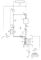
- the pump 9 of the circulation circuit 8 is driven to circulate the cooling water in the circuit 8, and the second path 8b is used as a path for circulating the cooling water.
- the switching valve 11 is switched. Furthermore, the shutoff state of the heater core 10 with respect to the circulation circuit 8 is released through the switching operation of the shutoff valve 15, and the cooling water circulating in the circulation circuit 8 by driving the Peltier element 16 is heated by the heating unit 16 a of the Peltier element 16. To do.
- the cooling water heated by the Peltier element 16 and having its temperature increased flows through the heater core 10.
- the air sent to the passenger compartment 1 is heated by the cooling water, and the heated air is sent to the passenger compartment 1 to heat the passenger compartment 1.
- the cooling water of the circulation circuit 8 is heated by the heating unit 16a of the Peltier element 16 through the driving of the Peltier element 16, the heat transfer from the cooling unit 16b to the heating unit 16a is performed in the Peltier element 16. Therefore, the temperature of the cooling part 16b is lowered.
- the control valve 19 of the cooling water circuit 17 is opened, and the part corresponding to the cooling part 16b of the Peltier element 16 in the cooling water circuit 17 and the above-mentioned
- the cooling water in the cooling water circuit 17 is circulated by allowing the cooling water to come and go between the common part with the one path 8 a and driving the pump 18.
- the cooling water of the cooling water circuit 17 When the cooling water of the cooling water circuit 17 is circulated in this way, even if the cooling water is cooled by the cooling portion 16b of the Peltier element 16, heat is generated between the cooling water and the outside air when passing through the radiator 12. It is suppressed that the temperature of the cooling water is excessively lowered after the replacement. Furthermore, since the cooling water in which the temperature reduction is suppressed in this way and the cooling portion 16b of the Peltier element 16 are heat-exchanged, the temperature reduction of the cooling portion 16b is also suppressed.
- the compressor 3 of the cooler 2 is in a drive stop state. For this reason, the air sent to the passenger compartment 1 is not cooled by the cooler 2.
- This mode is used to heat the passenger compartment 1 when the hybrid vehicle motor generator and the internal combustion engine 7 are used together or when the internal combustion engine 7 is operated alone, in other words, when the internal combustion engine 7 is operated. Is called. Under such circumstances, since the heat generation from the internal combustion engine 7 increases, it becomes possible to use the internal combustion engine 7 as a heat source for heating the cabin 1 (temperature increase). Therefore, in the first mode, when the air sent to the passenger compartment 1 is heated to heat the passenger compartment 1, the air is heated using the heat of the internal combustion engine 7.
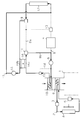
- the pump 9 of the circulation circuit 8 is driven to circulate the cooling water in the circuit 8, and the first path 8a is used as a path for circulating the cooling water.
- the switching valve 11 is switched. Further, the shutoff state of the heater core 10 with respect to the circulation circuit 8 is released through the switching operation of the shutoff valve 15.
- the cooling water whose temperature has risen due to heat received from the internal combustion engine 7 flows through the heater core 10.
- the air sent to the passenger compartment 1 is heated by the cooling water, and the heated air is sent to the passenger compartment 1 to heat the passenger compartment 1.
- the thermostat 13 causes the cooling water radiator 12 will be allowed to pass. As a result, the cooling water circulating in the circulation circuit 8 is caused to flow to the radiator 12. Thus, since the cooling water that has flowed to the radiator 12 is cooled by the outside air, the temperature of the cooling water that circulates in the circulation circuit 8 is suppressed from rising excessively.
- the Peltier element 16 In the second mode, the Peltier element 16 is stopped. For this reason, the cooling water circulating in the circulation circuit 8 is not heated by the heating part 16 a of the Peltier element 16. Even in the second mode, the compressor 3 of the cooler 2 is stopped. For this reason, the air sent to the passenger compartment 1 is not cooled by the cooler 2.
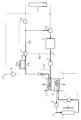
- the cooling water is circulated in the circuit 8 by driving the pump 9 of the circulation circuit 8, and the switching valve 11 is switched so that the first path 8a is used as a path for circulating the cooling water.
- the heater core 10 is shut off from the circulation circuit 8 through the switching operation of the shut-off valve 15 so that the high-temperature cooling water circulating in the circulation circuit 8 does not flow into the heater core 10.
- This mode is for dehumidifying and heating the passenger compartment 1 when the hybrid vehicle motor generator and the internal combustion engine 7 are used in combination or when the internal combustion engine 7 is operated alone, that is, when the internal combustion engine 7 is operated.
- the air sent to the passenger compartment 1 is heated in the same manner as in the second mode (FIG. 3), and in the passenger compartment 1 as in the third mode (FIG. 4). Cooling of the air sent is performed. Thereby, the dehumidification heating of the compartment 1 is performed similarly to the 4th mode.
- This air conditioning routine is periodically executed through the electronic control unit 20 by, for example, a time interruption every predetermined time.
- the operation mode of the air conditioner is switched to one of the first to fifth modes based on the presence / absence of various requests such as a cooling request, a heating request, and a dehumidification request for the passenger compartment 1.
- the presence or absence of a cooling request or a heating request for the passenger compartment 1 can be determined based on, for example, the actual temperature in the passenger compartment 1, the target temperature of the passenger compartment set by the passenger, and the like.
- the presence / absence of a dehumidification request in the passenger compartment 1 can be determined according to, for example, the operation position of a switch related to dehumidification operated by a passenger.
- the air conditioner In the air conditioning routine, if there is a cooling request for the passenger compartment 1 (S101: NO), the air conditioner is operated in the third mode to cool the passenger compartment 1 (S110). On the other hand, if it is determined in S101 that there is no cooling request for the passenger compartment 1, it is determined whether there is a heating request for the passenger compartment 1 (S102). If an affirmative determination is made here, it is determined whether or not the vehicle is running with only the motor generator, in other words, whether or not it is difficult to heat the passenger compartment 1 using the heat of the internal combustion engine 7. (S103). If an affirmative determination is made in S103, it is determined whether or not there is a request for dehumidification of the passenger compartment 1 (S104).
- the air conditioner is operated in the first mode to heat the passenger compartment 1 (S105). If the determination in S104 is negative, the air conditioner is in order to perform dehumidification heating of the passenger compartment 1. It is operated in the 4 mode (S106).
- the electronic control unit 20 and the switching valve 11 switch the path for circulating the cooling water in the circulation circuit 8 to the second path 8b and the Peltier element 16 It functions as a control unit for heating the heating unit 16a.
- the vehicle compartment 1 It is determined whether there is a request for dehumidification (S107). If the determination in S107 is affirmative, the air conditioner is operated in the second mode to heat the passenger compartment 1 (S108). If the determination in S107 is negative, the air conditioner is required to perform dehumidification heating of the passenger compartment 1. It is operated in the 5 mode (S109).
- the electronic control unit 20 and the switching valve 11 switch the path for circulating the cooling water in the circulation circuit 8 to the first path 8a and the Peltier element 16 It functions as a control unit for heating the heating unit 16a.
- the cooling is performed by the cooler 2 which is a vapor compression heat pump. Further, when heating the air sent to the passenger compartment 1 for temperature adjustment (air conditioning) of the passenger compartment 1, the heating is realized by using the heat of the internal combustion engine 7 or by the Peltier element 16. It is possible to do.
- the thing provided in the conventional air conditioner can be utilized as the said cooler 2, it can avoid that the structure of an air conditioner changes significantly. Even when it is difficult to use the internal combustion engine 7 as a heat source for air conditioning of the passenger compartment 1 such as when running only with a motor generator, air sent to the passenger compartment 1 is transmitted by the Peltier element 16. Since it can heat, it becomes possible to air-condition a vehicle (heating). Therefore, in a vehicle in which it is difficult to use the internal combustion engine 7 as a heat source for air conditioning the passenger compartment, the passenger compartment can be air-conditioned without significantly changing the structure.
- the cooling water is circulated through the circulation circuit 8. Can be collected and used for air conditioning (heating) of the passenger compartment 1.
- the circulation circuit 8 includes a first path 8a for realizing the passage of the cooling water circulating inside the internal combustion engine 7 and a second path 8b for realizing the bypass of the cooling water internal combustion engine 7. And one of the first path 8a and the second path 8b is used as a path for circulating the cooling water.
- the second path 8b is selected when the internal combustion engine 7 generates a small amount of heat
- the first path 8a is selected when the internal combustion engine 7 generates a large amount of heat. It becomes possible to do.
- the electronic control device 20 and the switching valve 11 are used.
- the path for circulating the cooling water in the circulation circuit 8 is switched to the second path 8b.
- the heating part 16a of the Peltier element 16 is heated, and the cooling water of the circulation circuit 8 is heated by the heating part 16a.
- the electronic control device 20 and the switching valve 11 are used to circulate the circuit 8.
- the path for circulating the cooling water at is switched to the first path 8a. Further, at this time, the heating of the heating part 16a of the Peltier element 16 is stopped, whereby the heating of the cooling water in the circulation circuit 8 by the heating part 16a is also stopped.
- the second path 8b As described above as the path for circulating the cooling water in the circulation circuit 8 when the passenger compartment 1 is heated while the hybrid vehicle is running with the internal combustion engine 7 stopped.
- the heat of the cooling water heated by the heating part 16 a of the Peltier element 16 is not taken away by the internal combustion engine 7. For this reason, the effective cooling water heating by the heating part 16a of the Peltier element 16 can be performed.
- the first path 8a is selected as the path for circulating the cooling water in the circulation circuit 8 as described above.
- the cooling water can be heated by the internal combustion engine 7 without being heated by the heating portion 16a of the Peltier element 16. For this reason, the heating of the heating part 16a of the Peltier element 16 can be stopped, and thereby unnecessary driving of the Peltier element 16 can be avoided.
- the cooling water circuit 17 that circulates the cooling water that exchanges heat with the cooling unit 16b of the Peltier element 16 guides the cooling water to the radiator 12 of the circulation circuit 8, and the radiator 12 uses the cooling water and the outside air. Let the heat exchange occur. It is suppressed that the temperature of the cooling water in the cooling water circuit 17 becomes excessively low due to such heat exchange, and as a result, the temperature of the cooling portion 16b of the Peltier element 16 that exchanges heat with the cooling water is also suppressed from excessively decreasing. .
- the Peltier element 16 is more efficient in transferring heat from the cooling unit 16b to the heating unit 16a, in other words, heating the cooling water in the circulation circuit 8 by the heating unit 16a. Can be done well. Therefore, by suppressing the temperature drop of the cooling part 16b in the Peltier element 16 as described above, the temperature difference between the heating part 16a of the Peltier element 16 and the cooling part 16b can be suppressed small, and the heating part of the Peltier element 16 Thus, the cooling water can be efficiently heated.
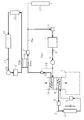
- the cooling water circuit 17 is different from that of the first embodiment.
- the cooling water circuit 17 is provided independently from the circulation circuit 8.
- the cooling water circuit 17 cools various electric devices such as the motor generator 21 and the electronic device 22 such as an inverter with the cooling water circulating therethrough.
- the motor generator 21 functions as a prime mover of the hybrid vehicle, and is driven and controlled by the electronic control unit 20.
- the cooling water circuit 17 includes a heat exchanger 23 that causes the cooling water circulating therethrough to exchange heat between the cooling water and the outside air.
- FIGS. 9 to 13 The first to fifth modes of the air conditioner are shown in FIGS. 9 to 13, respectively.
- the cooling water in the cooling water circuit 17 is circulated through the drive of the pump 18 in any of the first to fifth modes.
- various electric devices such as the motor generator 21 and the electronic device 22 such as an inverter in the hybrid vehicle are cooled by the cooling water of the cooling water circuit 17.
- heat is transferred from the cooling unit 16b to the heating unit 16a by driving the Peltier element 16, in other words, the cooling water of the circulation circuit 8 by the heating unit 16a. Is heated. At this time, a temperature drop occurs in the cooling portion 16b of the Peltier element 16. Then, the cooling water whose temperature is reduced by heat exchange between the cooling unit 16b and the cooling water of the cooling water circuit 17 is used for cooling the electric devices (the motor generator 21 and the electronic device 22). On the other hand, since the cooling water circulating in the cooling water circuit 17 receives heat from the electric device, the temperature of the cooling water is prevented from excessively decreasing.
- the following effects can be obtained. (5) In the first mode and the fourth mode of the air conditioner, even if the cooling water of the cooling water circuit 17 is cooled by the cooling unit 16b as the temperature of the cooling unit 16b of the Peltier element 16 decreases, Since the heat from the electric device is received, an excessive decrease in the temperature of the cooling water is suppressed. For this reason, it is suppressed that the cooling part 16b of the Peltier device 16 heat-exchanged with the said cooling water also falls too much.
- the temperature difference between the heating unit 16a and the cooling unit 16b in the Peltier element 16 is suppressed to be small, and as a result, the heating by the heating unit 16a of the Peltier element 16 is efficiently performed. It becomes like this.
- the temperature difference between the heating unit 16a and the cooling unit 16b of the Peltier element 16 can be suppressed small.
- the cooling water of the circulation circuit 8 is efficiently heated by the heating portion 16a of the Peltier element 16.
- each said embodiment can also be changed as follows, for example.
- auxiliary heating by the Peltier element 16 of the cooling water in the circulation circuit 8 may be performed in the second mode or the fifth mode.
- the second path 8b and the switching valve 11 in the circulation circuit 8 may be omitted, and the cooling water circulating in the circuit 8 may always pass through the internal combustion engine 7. In the first and second embodiments, it is not always necessary to exchange heat between the cooling unit 16 b of the Peltier element 16 and the cooling water of the cooling water circuit 17.
- the air sent to the passenger compartment 1 may be directly heated by the heating unit 16a of the Peltier element 16.
- SYMBOLS 1 Vehicle compartment, 2 ... Cooling machine, 3 ... Compressor, 4 ... Condenser, 5 ... Expansion valve, 6 ... Evaporator, 7 ... Internal combustion engine, 8 ... Circulation circuit, 9 ... Pump, 10 ... Heater core, 8a ... 1st path
Landscapes
- Engineering & Computer Science (AREA)
- Physics & Mathematics (AREA)
- Thermal Sciences (AREA)
- Mechanical Engineering (AREA)
- Chemical & Material Sciences (AREA)
- Combustion & Propulsion (AREA)
- Life Sciences & Earth Sciences (AREA)
- Sustainable Development (AREA)
- Sustainable Energy (AREA)
- General Engineering & Computer Science (AREA)
- Air-Conditioning For Vehicles (AREA)
- Electric Propulsion And Braking For Vehicles (AREA)
Abstract
Description
以下、本発明を、ハイブリッド自動車の空調装置に具体化した第1実施形態について、図1~図7を参照して説明する。
このモードは、ハイブリッド自動車のモータジェネレータのみによる走行時、言い換えれば内燃機関7を停止させた状態での走行時に車室1を暖房するために行われる。ハイブリッド自動車のモータジェネレータのみによる走行時には、内燃機関7からの発熱が少なくなることから、車室1の暖房(温度上昇)を行うための熱源として内燃機関7を利用することが困難になる。このため、第1モードでは、車室1に送られる空気を加熱して同車室1を暖房する際、その空気の加熱がペルチェ素子16によって行われる。
[第2モード]
このモードは、ハイブリッド自動車のモータジェネレータと内燃機関7との併用による走行時もしくは同機関7のみによる走行時、言い換えれば内燃機関7を運転した状態での走行時に車室1を暖房するために行われる。こうした状況のもとでは、内燃機関7からの発熱が多くなることから、車室1の暖房(温度上昇)を行うための熱源として内燃機関7を利用することが可能になる。このため、第1モードでは、車室1に送られる空気を加熱して同車室1を暖房する際、その空気の加熱が内燃機関7の熱を利用して行われる。
このモードは、車室1を冷房する際に行われる。具体的には、図4に示すように、冷却機2のコンプレッサ3を駆動して同冷却機2の冷媒を循環させることにより、エバポレータ6を低温の冷媒が通過して車室1に送られる空気が同冷媒によって冷却されるようにする。そして、このように冷却された空気が車室1に送られることで同車室1が冷房されるようになる。
このモードは、ハイブリッド自動車のモータジェネレータのみによる走行時、言い換えれば内燃機関7を停止させた状態での走行時に、車室1を除湿暖房するために行われる。具体的には、図5に示すように、第1モード(図2)と同様に車室1に送られる空気の加熱が行われるとともに、第3モード(図4)と同様に車室1に送られる空気の冷却が行われる。その結果、車室1に送られる空気は、ヒータコア10にて加熱された状態でエバポレータ6にて除湿されるようになり、それによって温度上昇し且つ水分の少ない状態となる。こうした空気を車室1に送ることで同車室1の除湿暖房が行われる。
このモードは、ハイブリッド自動車のモータジェネレータと内燃機関7との併用による走行時もしくは同機関7のみによる走行時、言い換えれば内燃機関7を運転した状態での走行時に、車室1を除湿暖房するために行われる。具体的には、図6に示すように、第2モード(図3)と同様に車室1に送られる空気の加熱が行われるとともに、第3モード(図4)と同様に車室1に送られる空気の冷却が行われる。これにより、第4モードと同様に車室1の除湿暖房が行われる。
一方、S101で車室1の冷房要求がない旨判断されると、車室1の暖房要求があるか否かが判断される(S102)。ここで肯定判定であれば、モータジェネレータのみでの走行時であるか否か、言い換えれば内燃機関7の熱を利用しての車室1の暖房が困難な状況であるか否かが判断される(S103)。このS103で肯定判定がなされると、車室1の除湿要求があるか否かが判断される(S104)。そして、S104で肯定判定であれば車室1の暖房を行うべく空調装置が第1モードで動作され(S105)、S104で否定判定であれば車室1の除湿暖房を行うべく空調装置が第4モードで動作される(S106)。なお、空調装置が第1モードまたは第4モードで動作するとき、電子制御装置20及び切換弁11は、循環回路8における冷却水を循環させるための経路を第2経路8bに切り換えるとともにペルチェ素子16の加熱部16aを加熱させる制御部として機能する。
(1)車室1の温度調節(空調)のために同車室1に送られる空気を冷却する場合、その冷却は蒸気圧縮式のヒートポンプである冷却機2によって行われる。また、車室1の温度調節(空調)のために同車室1に送られる空気を加熱する場合、その加熱については内燃機関7の熱を利用して実現したり、ペルチェ素子16によっても実現したりすることが可能である。ここで、上記冷却機2としては従来の空調装置に設けられていたものを利用することができるため、空調装置の構造が大幅に変わることを避けることができる。また、モータジェネレータのみでの走行時など、車室1の空調を行うための熱源として内燃機関7を利用することが困難な状況であっても、車室1に送られる空気をペルチェ素子16で加熱することができるため、車室の空調(暖房)を行うことが可能になる。従って、車室の空調を行うための熱源として内燃機関7を利用することが困難な車両において、構造を大幅に変えることなく車室の空調を行うことができる。
次に、本発明の第2実施形態を図8~図13に基づき説明する。
図8に示すように、この実施形態の空調装置では、冷却水回路17が第1実施形態と異なっている。同冷却水回路17は、循環回路8から独立して設けられている。また、冷却水回路17は、そこを循環する冷却水により、モータジェネレータ21やインバータ等の電子機器22といった各種の電気機器を冷却する。上記モータジェネレータ21は、ハイブリッド自動車の原動機として機能するものであり、電子制御装置20によって駆動制御される。更に、冷却水回路17は、そこを循環する冷却水を流して同冷却水と外気との熱交換を行わせる熱交換器23を備えている。
(5)空調装置の第1モード及び第4モードにおいて、ペルチェ素子16の冷却部16bの温度低下に伴い同冷却部16bによって冷却水回路17の冷却水が冷却されるとしても、その冷却水は上記電気機器からの熱を受けるため、同冷却水の温度が過度に低下することは抑制される。このため、上記冷却水と熱交換されるペルチェ素子16の冷却部16bも過度に温度低下することは抑制される。このように冷却部16bの温度低下を抑制することで、ペルチェ素子16における加熱部16aと冷却部16bとの温度差が小さく抑えられ、ひいてはペルチェ素子16の加熱部16aによる加熱が効率よく行われるようになる。
なお、上記各実施形態は、例えば以下のように変更することもできる。
・第1及び第2実施形態において、第2モードもしくは第5モードで循環回路8の冷却水のペルチェ素子16による補助的な加熱を行ってもよい。
・第1及び第2実施形態において、ペルチェ素子16の冷却部16bを必ずしも冷却水回路17の冷却水と熱交換させる必要はない。
Claims (7)
- 車室に送られる空気を冷却したり加熱したりすることで車室内の温度を調節する車両の空調装置において、
前記車室に送られる空気を冷却する冷却機と、
前記車室に送られる空気を加熱するペルチェ素子と、
を備えることを特徴とする車両の空調装置。 - 請求項1記載の車両の空調装置において、
車両に搭載される内燃機関と熱交換される冷却水を循環させるとともに前記車室に送られる空気を前記冷却水によって加熱する循環回路を備えており、
前記ペルチェ素子は、その加熱部による前記循環回路の冷却水の加熱を通じて、前記車室に送られる空気を加熱する
ことを特徴とする車両の空調装置。 - 前記循環回路は、そこを循環する冷却水の内燃機関の内部の通過を実現する第1経路と、前記冷却水の内燃機関のバイパスを実現する第2経路とを備えており、冷却水を循環させるための経路として前記第1経路と前記第2経路との一方を用いる請求項2記載の車両の空調装置。
- 前記循環回路は、そこを循環する冷却水の温度が予め定められた判定値以上のとき、その冷却水を流して同冷却水と外気との熱交換を行わせるラジエータを備えており、
前記ペルチェ素子は、冷却水回路を循環する冷却水との間で熱交換を行う冷却部を備えており、
前記冷却水回路は、そこを循環する冷却水を前記ラジエータに導いて同ラジエータにて前記冷却水と外気との熱交換を行わせる請求項2または3記載の車両の空調装置。 - 前記ペルチェ素子は、冷却水回路を循環する冷却水との間で熱交換を行う冷却部を備えており、
前記冷却水回路は、そこを循環する冷却水により車両に搭載された電気機器を冷却する請求項2または3記載の車両の空調装置。 - 前記冷却水回路は、そこを循環する冷却水を流して同冷却水と外気との熱交換を行わせる熱交換器を備えている請求項5記載の車両の空調装置。
- 請求項3記載の車両の空調装置において、
前記内燃機関を停止させた状態での車両の走行時に前記車室の暖房を行う際には、前記循環回路における冷却水を循環させるための経路を前記第2経路に切り換えるとともに前記ペルチェ素子の加熱部を加熱させ、前記内燃機関を運転した状態での車両の走行時に前記車室の暖房を行う際には、前記循環回路における冷却水を循環させるための経路を前記第1経路に切り換えるとともに前記ペルチェ素子の加熱部の加熱を停止させる制御部を備えることを特徴とする車両の空調装置。
Priority Applications (7)
| Application Number | Priority Date | Filing Date | Title |
|---|---|---|---|
| US14/002,335 US20130333395A1 (en) | 2011-03-04 | 2011-03-04 | Vehicle air-conditioning apparatus |
| RU2013142681/11A RU2555567C2 (ru) | 2011-03-04 | 2011-03-04 | Автомобильный кондиционер |
| PCT/JP2011/055132 WO2012120603A1 (ja) | 2011-03-04 | 2011-03-04 | 車両の空調装置 |
| KR1020137023426A KR20130124554A (ko) | 2011-03-04 | 2011-03-04 | 차량의 공조 장치 |
| EP11860157.4A EP2682291B1 (en) | 2011-03-04 | 2011-03-04 | Vehicle air-conditioning apparatus |
| CN2011800689042A CN103402796A (zh) | 2011-03-04 | 2011-03-04 | 车辆的空调装置 |
| JP2013503253A JP5817824B2 (ja) | 2011-03-04 | 2011-03-04 | 車両の空調装置 |
Applications Claiming Priority (1)
| Application Number | Priority Date | Filing Date | Title |
|---|---|---|---|
| PCT/JP2011/055132 WO2012120603A1 (ja) | 2011-03-04 | 2011-03-04 | 車両の空調装置 |
Publications (1)
| Publication Number | Publication Date |
|---|---|
| WO2012120603A1 true WO2012120603A1 (ja) | 2012-09-13 |
Family
ID=46797613
Family Applications (1)
| Application Number | Title | Priority Date | Filing Date |
|---|---|---|---|
| PCT/JP2011/055132 WO2012120603A1 (ja) | 2011-03-04 | 2011-03-04 | 車両の空調装置 |
Country Status (7)
| Country | Link |
|---|---|
| US (1) | US20130333395A1 (ja) |
| EP (1) | EP2682291B1 (ja) |
| JP (1) | JP5817824B2 (ja) |
| KR (1) | KR20130124554A (ja) |
| CN (1) | CN103402796A (ja) |
| RU (1) | RU2555567C2 (ja) |
| WO (1) | WO2012120603A1 (ja) |
Cited By (5)
| Publication number | Priority date | Publication date | Assignee | Title |
|---|---|---|---|---|
| JP2014059134A (ja) * | 2012-09-18 | 2014-04-03 | Dr Ing Hcf Porsche Ag | 熱電ヒートポンプの配置構造 |
| US20140165596A1 (en) * | 2012-12-18 | 2014-06-19 | Dr. Ing. H.C.F. Porsche Aktiengesellschaft | Thermoelectric arrangement for use in a cooling system of a motor vehicle and cooling system having such a thermoelectric arrangement |
| CN104943503A (zh) * | 2015-06-01 | 2015-09-30 | 南京航空航天大学 | 车辆动力、制冷供能系统及其工作方法 |
| US10589594B2 (en) | 2012-07-18 | 2020-03-17 | Hanon Systems | Heat distribution in a motor vehicle |
| JP2021113625A (ja) * | 2020-01-16 | 2021-08-05 | 生活協同組合コープさっぽろ | 冷却システム |
Families Citing this family (6)
| Publication number | Priority date | Publication date | Assignee | Title |
|---|---|---|---|---|
| JP5533812B2 (ja) * | 2011-07-28 | 2014-06-25 | 株式会社デンソー | 車両用空調装置 |
| JP6269307B2 (ja) * | 2014-05-13 | 2018-01-31 | 株式会社デンソー | 車両用空調装置 |
| US9863671B2 (en) | 2014-07-29 | 2018-01-09 | Ford Global Technologies, Llc | Heat pump assisted engine cooling for electrified vehicles |
| KR101693964B1 (ko) * | 2015-02-23 | 2017-01-06 | 현대자동차주식회사 | 하이브리드 차량용 난방시스템 및 하이브리드 차량용 난방시스템의 제어방법 |
| US10486495B2 (en) * | 2017-06-16 | 2019-11-26 | Ford Global Technologies, Llc | Method and system to manage vehicle thermal conditions |
| US20230113329A1 (en) * | 2021-10-08 | 2023-04-13 | Paccar Inc | Thermoelectric cooling and heating system for non-idling vehicle |
Citations (2)
| Publication number | Priority date | Publication date | Assignee | Title |
|---|---|---|---|---|
| JP2006001530A (ja) * | 2004-05-10 | 2006-01-05 | Visteon Global Technologies Inc | ハイブリッド車のための車室内温度制御システム |
| JP2011001048A (ja) * | 2009-05-19 | 2011-01-06 | Toyota Industries Corp | 車両用空調システム |
Family Cites Families (12)
| Publication number | Priority date | Publication date | Assignee | Title |
|---|---|---|---|---|
| RU2129492C1 (ru) * | 1997-06-04 | 1999-04-27 | Общество с ограниченной ответственностью "МАК-БЭТ" | Термоэлектрический кондиционер |
| JP2000335230A (ja) * | 1999-03-24 | 2000-12-05 | Tgk Co Ltd | 車両用暖房装置 |
| RU14726U1 (ru) * | 2000-02-25 | 2000-08-20 | Швецов Андрей Владимирович | Устройство кондиционирования транспортного средства |
| JP2001260640A (ja) * | 2000-03-21 | 2001-09-26 | Calsonic Kansei Corp | 車両用暖房装置 |
| US7743614B2 (en) * | 2005-04-08 | 2010-06-29 | Bsst Llc | Thermoelectric-based heating and cooling system |
| US20070101737A1 (en) * | 2005-11-09 | 2007-05-10 | Masao Akei | Refrigeration system including thermoelectric heat recovery and actuation |
| KR101195839B1 (ko) * | 2006-07-21 | 2012-10-30 | 한라공조주식회사 | 열전소자 모듈을 이용한 자동차용 보조 냉난방장치 |
| KR20080008871A (ko) * | 2006-07-21 | 2008-01-24 | 한라공조주식회사 | 열전소자 모듈을 이용한 자동차용 보조 냉난방장치 |
| US7779639B2 (en) * | 2006-08-02 | 2010-08-24 | Bsst Llc | HVAC system for hybrid vehicles using thermoelectric devices |
| KR101193898B1 (ko) * | 2006-10-25 | 2012-10-29 | 한라공조주식회사 | 열전소자 모듈을 이용한 자동차 보조 냉난방장치 |
| US9038400B2 (en) * | 2009-05-18 | 2015-05-26 | Gentherm Incorporated | Temperature control system with thermoelectric device |
| JP5316819B2 (ja) * | 2010-12-13 | 2013-10-16 | 三菱自動車工業株式会社 | 車両用暖房装置 |
-
2011
- 2011-03-04 US US14/002,335 patent/US20130333395A1/en not_active Abandoned
- 2011-03-04 RU RU2013142681/11A patent/RU2555567C2/ru active
- 2011-03-04 JP JP2013503253A patent/JP5817824B2/ja not_active Expired - Fee Related
- 2011-03-04 EP EP11860157.4A patent/EP2682291B1/en not_active Not-in-force
- 2011-03-04 WO PCT/JP2011/055132 patent/WO2012120603A1/ja active Application Filing
- 2011-03-04 CN CN2011800689042A patent/CN103402796A/zh active Pending
- 2011-03-04 KR KR1020137023426A patent/KR20130124554A/ko active Search and Examination
Patent Citations (2)
| Publication number | Priority date | Publication date | Assignee | Title |
|---|---|---|---|---|
| JP2006001530A (ja) * | 2004-05-10 | 2006-01-05 | Visteon Global Technologies Inc | ハイブリッド車のための車室内温度制御システム |
| JP2011001048A (ja) * | 2009-05-19 | 2011-01-06 | Toyota Industries Corp | 車両用空調システム |
Cited By (8)
| Publication number | Priority date | Publication date | Assignee | Title |
|---|---|---|---|---|
| US10589594B2 (en) | 2012-07-18 | 2020-03-17 | Hanon Systems | Heat distribution in a motor vehicle |
| JP2014059134A (ja) * | 2012-09-18 | 2014-04-03 | Dr Ing Hcf Porsche Ag | 熱電ヒートポンプの配置構造 |
| US20140165596A1 (en) * | 2012-12-18 | 2014-06-19 | Dr. Ing. H.C.F. Porsche Aktiengesellschaft | Thermoelectric arrangement for use in a cooling system of a motor vehicle and cooling system having such a thermoelectric arrangement |
| US9829219B2 (en) * | 2012-12-18 | 2017-11-28 | Dr. Ing. H.C.F. Porsche Aktiengesellschaft | Thermoelectric arrangement for use in a cooling system of a motor vehicle and cooling system having such a thermoelectric arrangement |
| CN104943503A (zh) * | 2015-06-01 | 2015-09-30 | 南京航空航天大学 | 车辆动力、制冷供能系统及其工作方法 |
| CN104943503B (zh) * | 2015-06-01 | 2017-03-29 | 南京航空航天大学 | 车辆动力、制冷供能系统及其工作方法 |
| JP2021113625A (ja) * | 2020-01-16 | 2021-08-05 | 生活協同組合コープさっぽろ | 冷却システム |
| JP7083363B2 (ja) | 2020-01-16 | 2022-06-10 | 生活協同組合コープさっぽろ | 冷却システム |
Also Published As
| Publication number | Publication date |
|---|---|
| RU2555567C2 (ru) | 2015-07-10 |
| EP2682291B1 (en) | 2017-11-08 |
| EP2682291A4 (en) | 2014-08-20 |
| RU2013142681A (ru) | 2015-04-10 |
| CN103402796A (zh) | 2013-11-20 |
| JPWO2012120603A1 (ja) | 2014-07-07 |
| KR20130124554A (ko) | 2013-11-14 |
| EP2682291A1 (en) | 2014-01-08 |
| JP5817824B2 (ja) | 2015-11-18 |
| US20130333395A1 (en) | 2013-12-19 |
Similar Documents
| Publication | Publication Date | Title |
|---|---|---|
| JP5817824B2 (ja) | 車両の空調装置 | |
| JP7095848B2 (ja) | 車両用空気調和装置 | |
| JP6743844B2 (ja) | 冷却水回路 | |
| JP7185469B2 (ja) | 車両の熱管理システム | |
| WO2018193770A1 (ja) | 車両用空気調和装置 | |
| US9573437B2 (en) | Vehicular air conditioning system | |
| WO2020031569A1 (ja) | 車両用空気調和装置 | |
| WO2020031568A1 (ja) | 車両用空気調和装置 | |
| US20170158019A1 (en) | Air conditioning device for vehicle | |
| JP7092429B2 (ja) | 車両用空気調和装置 | |
| JP6842375B2 (ja) | 車両用空気調和装置 | |
| JP7316872B2 (ja) | 車両搭載発熱機器の温度調整装置及びそれを備えた車両用空気調和装置 | |
| JP2020055344A (ja) | 車両の熱管理システム | |
| JP6963405B2 (ja) | 車両用空気調和装置 | |
| US9579951B2 (en) | Air conditioning device and method for air conditioning an interior and/or at least one component of an electric vehicle | |
| CN109203909B (zh) | 用于车辆的加热、通风和空调系统 | |
| JP2020142789A (ja) | 熱管理システム | |
| JP6203490B2 (ja) | 電気自動車用空調装置およびその運転方法 | |
| CN113015638A (zh) | 车用空调装置 | |
| JP7095845B2 (ja) | 複合弁及びそれを用いた車両用空気調和装置 | |
| JP2022546954A (ja) | 車両内のバッテリーの温度及び室内空気調和装置の温度の統合的制御システム | |
| WO2023203943A1 (ja) | 車両用空調装置 | |
| JP7559692B2 (ja) | 車両用熱マネジメントシステム | |
| JP7513962B2 (ja) | 車両用熱マネジメントシステム | |
| WO2023248714A1 (ja) | 車両用空調装置 |
Legal Events
| Date | Code | Title | Description |
|---|---|---|---|
| 121 | Ep: the epo has been informed by wipo that ep was designated in this application |
Ref document number: 11860157 Country of ref document: EP Kind code of ref document: A1 |
|
| REEP | Request for entry into the european phase |
Ref document number: 2011860157 Country of ref document: EP |
|
| ENP | Entry into the national phase |
Ref document number: 2013503253 Country of ref document: JP Kind code of ref document: A |
|
| WWE | Wipo information: entry into national phase |
Ref document number: 14002335 Country of ref document: US |
|
| ENP | Entry into the national phase |
Ref document number: 20137023426 Country of ref document: KR Kind code of ref document: A |
|
| NENP | Non-entry into the national phase |
Ref country code: DE |
|
| ENP | Entry into the national phase |
Ref document number: 2013142681 Country of ref document: RU Kind code of ref document: A |