WO2012117998A1 - 電子顕微鏡 - Google Patents
電子顕微鏡 Download PDFInfo
- Publication number
- WO2012117998A1 WO2012117998A1 PCT/JP2012/054728 JP2012054728W WO2012117998A1 WO 2012117998 A1 WO2012117998 A1 WO 2012117998A1 JP 2012054728 W JP2012054728 W JP 2012054728W WO 2012117998 A1 WO2012117998 A1 WO 2012117998A1
- Authority
- WO
- WIPO (PCT)
- Prior art keywords
- magnetic shield
- objective lens
- electron microscope
- sample chamber
- shield
- Prior art date
- Legal status (The legal status is an assumption and is not a legal conclusion. Google has not performed a legal analysis and makes no representation as to the accuracy of the status listed.)
- Ceased
Links
Images





Classifications
-
- H—ELECTRICITY
- H01—ELECTRIC ELEMENTS
- H01J—ELECTRIC DISCHARGE TUBES OR DISCHARGE LAMPS
- H01J37/00—Discharge tubes with provision for introducing objects or material to be exposed to the discharge, e.g. for the purpose of examination or processing thereof
- H01J37/02—Details
- H01J37/04—Arrangements of electrodes and associated parts for generating or controlling the discharge, e.g. electron-optical arrangement or ion-optical arrangement
-
- H—ELECTRICITY
- H01—ELECTRIC ELEMENTS
- H01J—ELECTRIC DISCHARGE TUBES OR DISCHARGE LAMPS
- H01J37/00—Discharge tubes with provision for introducing objects or material to be exposed to the discharge, e.g. for the purpose of examination or processing thereof
- H01J37/02—Details
- H01J37/04—Arrangements of electrodes and associated parts for generating or controlling the discharge, e.g. electron-optical arrangement or ion-optical arrangement
- H01J37/09—Diaphragms; Shields associated with electron or ion-optical arrangements; Compensation of disturbing fields
-
- H—ELECTRICITY
- H01—ELECTRIC ELEMENTS
- H01J—ELECTRIC DISCHARGE TUBES OR DISCHARGE LAMPS
- H01J37/00—Discharge tubes with provision for introducing objects or material to be exposed to the discharge, e.g. for the purpose of examination or processing thereof
- H01J37/02—Details
- H01J37/04—Arrangements of electrodes and associated parts for generating or controlling the discharge, e.g. electron-optical arrangement or ion-optical arrangement
- H01J37/10—Lenses
- H01J37/14—Lenses magnetic
-
- H—ELECTRICITY
- H01—ELECTRIC ELEMENTS
- H01J—ELECTRIC DISCHARGE TUBES OR DISCHARGE LAMPS
- H01J37/00—Discharge tubes with provision for introducing objects or material to be exposed to the discharge, e.g. for the purpose of examination or processing thereof
- H01J37/02—Details
- H01J37/16—Vessels; Containers
-
- H—ELECTRICITY
- H01—ELECTRIC ELEMENTS
- H01J—ELECTRIC DISCHARGE TUBES OR DISCHARGE LAMPS
- H01J2237/00—Discharge tubes exposing object to beam, e.g. for analysis treatment, etching, imaging
- H01J2237/02—Details
- H01J2237/026—Shields
- H01J2237/0264—Shields magnetic
Definitions
- the present invention relates to an electron microscope, and more particularly to an electron microscope having a high magnetic shielding effect.
- Patent Document 1 and Patent Document 2 show that an aluminum alloy or the like is used to reduce the weight of a sample chamber container or a lens barrel.
- the importance of the magnetic shield is shown, and regarding the arrangement of the magnetic shield, it is shown that a ferromagnetic material is arranged on the inner surface of the sample chamber container or the lens barrel.
- the magnetic shield is provided in the sample chamber container as shown in Patent Literature 1 and Patent Literature 2. It has been arranged along the inner surface.
- JP-A-61-59825 JP 2004-214110 A Japanese Patent Laid-Open No. 4-171645
- the magnetic shield is disposed along the inner surface of the sample chamber container. This magnetic shield is less effective for an electron microscope having a configuration having an objective lens protruding into the sample chamber space. For this reason, the magnetic field intensity in the electron beam orbital space fluctuates with the fluctuation of the environmental magnetic field, and the position of the electron beam shifts or the focus of the electron microscope shifts.
- An object of the present invention is to provide an electron microscope capable of enhancing the magnetic shield function even if it has a structure having an objective lens protruding into a sample chamber space.
- the electron microscope according to the present invention has the following basic features.
- An electron gun that generates an electron beam
- a lens barrel that houses the electron gun and a deflection lens
- an objective lens that converges the electron beam and irradiates the sample
- a sample that is located under the lens barrel and stores the sample
- a sample chamber container forming a sample chamber, a sample chamber magnetic shield provided inside the sample chamber container, and a cylindrical objective lens magnetic shield surrounding the objective lens.
- the upper plate serving as the upper wall of the sample chamber container and the upper shield of the sample chamber magnetic shield are provided with first and second holes facing each other in the traveling direction of the electron beam.
- the objective lens is held inside the first hole provided in the upper plate of the sample chamber container among the holes.
- the lower end of the objective lens is at a position lower than the lower end of the upper plate of the sample chamber container, and at the position of the second hole provided in the upper shield of the sample chamber magnetic shield or a position close to this position. Be placed.
- the sample is installed at a position facing the second hole inside the sample chamber magnetic shield.
- the objective lens magnetic shield is located inside the first hole, and its lower end is connected to the upper shield of the sample chamber magnetic shield.
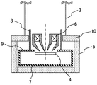
- FIG. 3 is a cross-sectional view of the periphery of the sample chamber of the electron microscope in Example 1.
- the perspective view of the sample chamber periphery of the electron microscope in Example 1 (a cross section differs from FIG. 2).
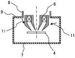
- Sectional drawing of the sample chamber periphery of the electron microscope in a comparative example Sectional drawing of the sample chamber periphery of the electron microscope in Example 2.
- FIG. 1 is a cross-sectional view showing an outline of the configuration of a general electron microscope.
- the electron microscope has a function of deflecting and converging an electron beam generated by the electron gun 1 with a lens (a deflection lens and an objective lens) 2 and irradiating the sample 4 with the electron beam.
- Many of the lens barrels 3 that store and hold the electron gun 1 and the lens 2 have a magnetic shielding effect.
- the sample 4 is stored in a sample chamber container 5 which is a vacuum container.
- the sample 4 emits secondary electrons when irradiated with an electron beam.
- the secondary electrons are captured by a secondary electron detector (not shown), whereby the sample 4 is inspected and imaged.
- the moving component is preferably made of a non-magnetic member.
- a direction from the sample 4 toward the electron gun 1 along the electron beam irradiation direction is defined as an upward direction
- a direction from the electron gun 1 toward the sample 4 is defined as a downward direction.
- the vertical positional relationship of the object follows this definition.
- the main features of the electron microscope according to the present invention are as follows.
- the sample is surrounded by a sample chamber magnetic shield provided inside the sample chamber container, and the periphery of the objective lens is surrounded by a cylindrical objective lens magnetic shield.
- the sample chamber magnetic shield is arranged so that the lower end of the upper part (upper shield) is the same height as or substantially the same height as the lower end of the objective lens.
- the objective lens magnetic shield is connected to the sample chamber magnetic shield.
- a first hole is provided in the upper plate serving as the upper wall of the sample chamber container, and a second hole is provided in the upper shield of the sample chamber magnetic shield, and the first hole and the second hole are provided. Are opposed in the direction of travel of the electron beam.
- the objective lens is held inside the first hole, and the lower end of the objective lens is arranged at a position lower than the lower end of the upper plate of the sample chamber container and at the position of the second hole or a position close to this position. Is done.
- the sample is placed inside the sample chamber magnetic shield at a position facing the second hole.
- the objective lens magnetic shield is located inside the first hole, and its lower end is connected to the upper shield of the sample chamber magnetic shield.
- the nonmagnetic used in the following is a characteristic having a relative magnetic permeability of 0.99 to 1.01
- the ferromagnetic is a characteristic having a relative magnetic permeability greater than 1.01.
- the shape of the objective lens is not limited to the shape described in the following examples and figures.
- an objective lens having a typical shape that is difficult to shield is exemplified.
- FIG. 2 and 3 show an outline of an electron microscope according to an embodiment of the present invention.
- FIG. 2 is a cross-sectional view of the periphery of the sample chamber of the electron microscope in the first embodiment
- FIG. 3 is a perspective view of the periphery of the sample chamber of the electron microscope in the first embodiment. 3 is different from FIG. 2 in the cross-sectional position.
- the objective lens 6 is generally disposed above the sample 4 and has a rotationally symmetric shape with the electron beam irradiation direction as the axial direction, and is made of a ferromagnetic material such as iron. Created with.
- an objective lens 6 having a shape as shown in FIG. 2 is used.
- the objective lens 6 is characterized in that the lower end (tip on the sample 4 side) protrudes into the internal space (sample chamber space) of the sample chamber container 5 so as to be close to the sample 4.
- the sample chamber container 5 generally has a box shape with a hole in the upper (electron gun side) container wall, and surrounds the sample 4 together with the objective lens 6 positioned in the hole.
- the upper (electron gun side) container wall is referred to as “sample chamber container upper plate 10”. Since the lower end of the objective lens 6 protrudes into the internal space of the sample chamber container 5, it is disposed at a position (position on the sample 4 side) lower than the lower end of the sample chamber container upper plate 10.
- the sample chamber container 5 needs to be made of a nonmagnetic material such as an aluminum alloy.
- a sample chamber magnetic shield 7 surrounding the sample is disposed.
- the sample chamber magnetic shield 7 is made of a ferromagnetic thin plate such as an iron-nickel alloy and has a box shape.
- the upper part (on the electron gun side) of the sample chamber magnetic shield 7 is referred to as an upper shield 9.
- a hole is provided in the upper shield 9 so as not to contact the objective lens 6, and the lower end of the objective lens 6 is disposed at the position of this hole. Therefore, the sample chamber magnetic shield 7 surrounds the sample 4 together with the lower end of the objective lens 6.
- the position of the lower end of the upper shield 9 in the height direction (electron beam irradiation direction) is the same as or substantially the same as the lower end (tip) of the objective lens 6.
- the upper shield 9 is disposed at a predetermined interval in the vertical direction (electron beam irradiation direction) from the sample chamber container upper plate 10. This predetermined interval can be determined according to the position of the lower end of the objective lens 6.
- the objective lens magnetic shield 8 is disposed around the objective lens.
- the objective lens magnetic shield 8 surrounds the objective lens 6 and has a cylindrical shape with the electron beam irradiation direction as the axial direction, and its lower end is connected to the upper shield 9 of the sample chamber magnetic shield 7.
- the objective lens magnetic shield 8 is also preferably made of a ferromagnetic thin plate such as an iron-nickel alloy and is not in contact with the objective lens 6.
- the tip of the objective lens 6 protrudes into the sample chamber space (the internal space of the sample chamber container 5) at a relatively acute angle with respect to the electron beam irradiation direction.
- the upper shield 9 of the sample chamber magnetic shield 7 can be extended toward the central axis of the lens barrel 3 so as to approach the objective lens 6. In this case, the hole provided in the upper shield 9 is smaller than the diameter of the objective lens magnetic shield 8.
- the upper shield 9 of the sample chamber magnetic shield 7 is horizontal (electron beam irradiation). The case where it is arranged perpendicular to the direction is shown.
- FIG. 4 is a cross-sectional view around the sample chamber of the electron microscope in a comparative example with the present embodiment.
- FIG. 4 shows an electron microscope in which the position in the height direction of the upper shield 9 of the sample chamber magnetic shield 7 is located above the objective lens 6.
- the objective lens 6 is made of a ferromagnetic material, the magnetic flux passes more easily than the sample chamber space. Therefore, the magnetic flux leaking from the magnetic shield (the sample chamber magnetic shield 7 and the objective lens magnetic shield 8) into the sample chamber becomes a magnetic flux 11 directed toward the objective lens 6. As a result, the change in the electron beam trajectory accompanying the change in the environmental magnetic field is likely to occur.
- the case where the upper shield 9 of the sample chamber magnetic shield 7 is arranged at the position of the lower end of the objective lens 6 is compared with the case where it is arranged 150 mm above this.
- the magnetic field change is reduced by about 20% when the upper shield 9 is arranged at the lower end position of the objective lens 6. It was confirmed that the magnetic shield characteristics were excellent.
- FIG. 5 is a cross-sectional view of the periphery of the sample chamber of the electron microscope in Example 2.
- the tip of the objective lens 6 protrudes into the sample chamber space (inner space of the sample chamber container 5) at an angle close to horizontal (perpendicular to the electron beam irradiation direction). That is, as compared with Example 1, the tip of the objective lens 6 is relatively horizontal and protrudes into the sample chamber space.
- the hole provided in the upper shield 9 of the sample chamber magnetic shield 7 is smaller than the diameter of the objective lens magnetic shield 8.
- the hole provided in the upper shield 9 is the objective lens magnetic shield. Is approximately equal to the diameter of 8.
- the objective lens magnetic shield 8 and the upper shield 9 in the present invention can be applied to any electron microscope regardless of the shape of the tip of the objective lens 6 by changing the diameter of the hole of the upper shield 9. Is possible.
- FIG. 6 is a cross-sectional view of the periphery of the sample chamber of the electron microscope in Example 3.
- the tilt of the sample 4 is variable by a sample driving stage (not shown).
- the upper shield 9 of the sample chamber magnetic shield 7 has a conical or polygonal pyramid shape that protrudes downward and has a hole at the lower end, thereby preventing interference with the tilted sample 4.
- the upper shield 9 is positioned closest to the objective lens 6 (the lower end of the cone or polygonal pyramid shape) so that the height direction position is equal to the lower end position of the objective lens 6.
- the objective lens magnetic shield 8 is connected to the upper shield 9 of the sample chamber magnetic shield 7.
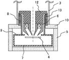
- FIG. 7 is a cross-sectional view around the sample chamber of the electron microscope in Example 4. In this embodiment, a support structure of the objective lens 6 is shown.
- the objective lens 6 is supported by a column (electron gun, lens, etc.) 12, and the column 12 is supported by a sample chamber container upper plate 10 via a support flange 13.
- the supporting flange 13 is provided on the upper part of the sample chamber container upper plate 10.
- the column 12 and the supporting flange 13 are arranged so as to have a space between them.
- the upper part of the objective lens magnetic shield 8 is located in the space between the support flange 13 and the column 12, and the lower part is connected to the upper shield 9 of the sample chamber magnetic shield 7.
- the position of the upper end of the objective lens magnetic shield 8 is above the position of the upper end of the objective lens 6.
- the objective lens magnetic shield 8 can be composed of a single thin ferromagnetic plate.
- the objective lens magnetic shield 8 can shield the objective lens 6 as an integrated object from a position above the upper end of the objective lens 6 to a position of the lower end, and has a high magnetic shielding effect. Is obtained.
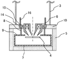
- FIG. 8 is a cross-sectional view of the periphery of the sample chamber of the electron microscope in Example 5.
- a support structure of the objective lens 6 different from that of the fourth embodiment is shown.
- the objective lens 6 is supported on the sample chamber container upper plate 10 via a nonmagnetic flange 15 and a ferromagnetic flange 14.
- the ferromagnetic flange 14 is disposed in the hole of the sample chamber container upper plate 10
- the nonmagnetic flange 15 is disposed in the ferromagnetic flange 14 to support the objective lens 6.
- the objective lens magnetic shield 8 and the upper objective lens magnetic shield 16 are arranged so as to be connected to the ferromagnetic flange 14.
- the upper objective lens magnetic shield 16 is made of a ferromagnetic thin plate such as an iron-nickel alloy in the same manner as the objective lens magnetic shield 8.
- the objective lens magnetic shield 8, the ferromagnetic flange 14, and the upper objective lens magnetic shield 16 may be made of the same ferromagnetic material or may be made of different ferromagnetic materials.
- the objective lens magnetic shield 8 Since the ferromagnetic flange 14 is connected to the objective lens magnetic shield 8 and the upper objective magnetic shield 16, the objective lens magnetic shield 8, the ferromagnetic flange 14, and the upper objective magnetic shield 16 are made of a continuous ferromagnetic material. It becomes the shape which consists of. Further, since the objective lens 6 and the ferromagnetic flange 14 do not contact with each other due to the nonmagnetic flange 15, and thus the objective lens 6 and the magnetic shield do not contact, this configuration has a high magnetic shielding effect. This configuration also has the effect of easily assembling an electron microscope.
- the objective lens magnetic shield 8, the ferromagnetic flange 14, and the upper objective lens magnetic shield 16 are shown as separate parts, but some or all of them may be formed as a single unit. .
- FIG. 9 is a cross-sectional view of the periphery of the sample chamber of the electron microscope in Example 6.
- a ferromagnetic ring 17 is disposed at a connection portion between the upper shield 9 of the sample chamber magnetic shield 7 and the objective lens magnetic shield 8.
- the ferromagnetic ring 17 is coaxial with the objective lens magnetic shield 8 and can be arranged along the objective lens magnetic shield 8 on the outside, inside, or both outside and inside of the objective lens magnetic shield 8.
- FIG. 9 shows a case in which both the outer side and the inner side are arranged.
- the ferromagnetic ring 17 is formed of a ferromagnetic thin plate such as an iron-nickel alloy in the same manner as the objective lens magnetic shield 8.
- the ferromagnetic ring 17, the objective lens magnetic shield 8 and the upper shield 9 may be made of the same ferromagnetic material or may be made of different ferromagnetic materials.
- the upper shield 9, the objective lens magnetic shield 8, and the ferromagnetic ring 17 are shown as separate parts, but some or all of them may be formed as a single body.
- the position in the height direction (electron beam irradiation direction) of the lower end of the upper shield 9 is arranged to be the same position as or substantially the same position as the lower end (tip end) of the objective lens 6. Accordingly, the position of the lower end of the objective lens magnetic shield 8 connected to the upper shield 9 is also the same position as or substantially the same position as the lower end of the objective lens 6.
- the position of the lower end of the objective lens magnetic shield 8 will be specifically described. It is most desirable that the lower end of the objective lens magnetic shield 8 is disposed above the lower end of the objective lens 6 within 3 millimeters (in a direction approaching the electron gun). However, if this arrangement is difficult, it is desirable to arrange the objective lens 6 upward within 10 millimeters from the lower end of the objective lens 6. At least from the lower end of the objective lens 6, it is necessary to arrange it within 30 millimeters.
- the objective lens magnetic shield 8 has a cylindrical shape.
- the shape of the objective lens magnetic shield 8 is not limited to a cylindrical shape.
- it may be a substantially cylindrical shape or a polygonal cylinder in which a single plate is rolled and the opposite sides are joined, and the joining portions overlap.
- the ferromagnetic ring 17 described in Example 6 has a shape along the objective lens magnetic shield 8 even when the objective lens magnetic shield 8 is not cylindrical. That is, the shape of the ferromagnetic ring 17 is changed in accordance with the shape of the objective lens magnetic shield 8. For example, when the objective lens magnetic shield 8 is a polygonal cylinder, the ferromagnetic ring 17 is a polygonal ring.
- the sample chamber magnetic shield 7 has a box shape.
- the shape of the sample chamber magnetic shield 7 is not limited to the box shape.
- a cylindrical shape with a lid on the top and bottom or a polygonal box shape may be used.
Landscapes
- Chemical & Material Sciences (AREA)
- Analytical Chemistry (AREA)
- Electron Sources, Ion Sources (AREA)
Abstract
Description
本発明の他の目的、特徴及び利点は添付図面に関する以下の本発明の実施例の記載から明らかになるであろう。
上記記載は実施例についてなされたが、本発明はそれに限らず、本発明の精神と添付の請求の範囲の範囲内で種々の変更および修正をすることができることは当業者に明らかである。
2 レンズ
3 鏡筒
4 試料
5 試料室容器
6 対物レンズ
7 試料室磁気シールド
8 対物レンズ磁気シールド
9 上部シールド
10 試料室容器上板
11 対物レンズに向かう磁束
12 カラム
13 支持用フランジ
14 強磁性フランジ
15 非磁性フランジ
16 上部対物レンズ磁気シールド
17 強磁性リング
Claims (16)
- 電子線を発生させる電子銃と、前記電子銃及び偏向レンズを収納する鏡筒と、前記電子線を収束させて試料に照射する対物レンズと、前記鏡筒の下に位置して前記試料を収納する試料室を形成する試料室容器と、前記試料室容器の内部に設けられた試料室磁気シールドと、前記対物レンズの周囲を囲む筒形の対物レンズ磁気シールドと、を備える電子顕微鏡であって、
前記試料室容器の上部壁となる上板と前記試料室磁気シールドの上部シールドに、前記電子線の進行方向で対向する第1、第2の穴が設けられ、
前記対物レンズは、前記穴のうち前記試料室容器の上板に設けられた前記第1の穴の内側で保持され、前記対物レンズの下端は、前記試料室容器の上板の下端よりも低い位置に、かつ前記試料室磁気シールドの上部シールドに設けられた前記第2の穴の位置またはこの位置に接近した位置に配置され、
前記試料は、前記試料室磁気シールドの内側で前記第2の穴に臨む位置に設置され、
前記対物レンズ磁気シールドは、前記第1の穴の内側に位置して、その下端が前記試料室磁気シールドの上部シールドと接続される、
ことを特徴とする電子顕微鏡。 - 請求項1記載の電子顕微鏡であって、
前記試料室磁気シールドは、前記上部シールドが前記電子線の照射方向に対して垂直に配置される電子顕微鏡。 - 請求項1記載の電子顕微鏡であって、
前記試料室磁気シールドは、前記上部シールドが下に凸であり下端に穴を有する円錐または多角錐の側面の形状である電子顕微鏡。 - 請求項1記載の電子顕微鏡であって、
前記対物レンズ磁気シールドは、前記電子銃側の端の位置が、前記対物レンズの前記電子銃側の端の位置よりも、前記電子銃側にある電子顕微鏡。 - 請求項4記載の電子顕微鏡であって、
前記対物レンズ磁気シールドは、前記試料側の端から前記電子銃側の端までが1つの部品から構成される電子顕微鏡。 - 請求項4記載の電子顕微鏡であって、
前記対物レンズ磁気シールドは、前記試料側の端から前記電子銃側の端までが複数の部品から構成される電子顕微鏡。 - 請求項1記載の電子顕微鏡であって、
前記試料室磁気シールドの上部シールドは、前記試料室容器の上板と、前記電子線の照射方向に、前記対物レンズの前記試料側の先端の位置に応じて定まる所定の間隔を隔てて配置される電子顕微鏡。 - 請求項4記載の電子顕微鏡であって、
前記試料室磁気シールドの上部シールドは、前記試料室容器の上板と、前記電子線の照射方向に、前記対物レンズの前記試料側の先端の位置に応じて定まる所定の間隔を隔てて配置される電子顕微鏡。 - 請求項1記載の電子顕微鏡であって、
前記試料室磁気シールドと前記対物レンズ磁気シールドの接続箇所に、強磁性体からなり、前記対物レンズ磁気シールドに沿うリング状部材を有する電子顕微鏡。 - 請求項2記載の電子顕微鏡であって、
前記試料室磁気シールドと前記対物レンズ磁気シールドの接続箇所に、強磁性体からなり、前記対物レンズ磁気シールドに沿うリング状部材を有する電子顕微鏡。 - 請求項3記載の電子顕微鏡であって、
前記試料室磁気シールドと前記対物レンズ磁気シールドの接続箇所に、強磁性体からなり、前記対物レンズ磁気シールドに沿うリング状部材を有する電子顕微鏡。 - 請求項4記載の電子顕微鏡であって、
前記試料室磁気シールドと前記対物レンズ磁気シールドの接続箇所に、強磁性体からなり、前記対物レンズ磁気シールドに沿うリング状部材を有する電子顕微鏡。 - 請求項5記載の電子顕微鏡であって、
前記試料室磁気シールドと前記対物レンズ磁気シールドの接続箇所に、強磁性体からなり、前記対物レンズ磁気シールドに沿うリング状部材を有する電子顕微鏡。 - 請求項6記載の電子顕微鏡であって、
前記試料室磁気シールドと前記対物レンズ磁気シールドの接続箇所に、強磁性体からなり、前記対物レンズ磁気シールドに沿うリング状部材を有する電子顕微鏡。 - 請求項7記載の電子顕微鏡であって、
前記試料室磁気シールドと前記対物レンズ磁気シールドの接続箇所に、強磁性体からなり、前記対物レンズ磁気シールドに沿うリング状部材を有する電子顕微鏡。 - 請求項8記載の電子顕微鏡であって、
前記試料室磁気シールドと前記対物レンズ磁気シールドの接続箇所に、強磁性体からなり、前記対物レンズ磁気シールドに沿うリング状部材を有する電子顕微鏡。
Priority Applications (2)
| Application Number | Priority Date | Filing Date | Title |
|---|---|---|---|
| DE112012000544.9T DE112012000544B4 (de) | 2011-02-28 | 2012-02-27 | Elektronenmikroskop |
| US13/984,329 US9006653B2 (en) | 2011-02-28 | 2012-02-27 | Electron microscope |
Applications Claiming Priority (2)
| Application Number | Priority Date | Filing Date | Title |
|---|---|---|---|
| JP2011041205A JP5485927B2 (ja) | 2011-02-28 | 2011-02-28 | 電子顕微鏡 |
| JP2011-041205 | 2011-02-28 |
Publications (1)
| Publication Number | Publication Date |
|---|---|
| WO2012117998A1 true WO2012117998A1 (ja) | 2012-09-07 |
Family
ID=46757932
Family Applications (1)
| Application Number | Title | Priority Date | Filing Date |
|---|---|---|---|
| PCT/JP2012/054728 Ceased WO2012117998A1 (ja) | 2011-02-28 | 2012-02-27 | 電子顕微鏡 |
Country Status (4)
| Country | Link |
|---|---|
| US (1) | US9006653B2 (ja) |
| JP (1) | JP5485927B2 (ja) |
| DE (1) | DE112012000544B4 (ja) |
| WO (1) | WO2012117998A1 (ja) |
Families Citing this family (6)
| Publication number | Priority date | Publication date | Assignee | Title |
|---|---|---|---|---|
| TWI660400B (zh) * | 2013-12-13 | 2019-05-21 | Ebara Corporation | 頂板開關機構及檢查裝置 |
| JP6267948B2 (ja) * | 2013-12-13 | 2018-01-24 | 株式会社荏原製作所 | 真空磁気遮蔽容器の構造 |
| US11927549B2 (en) * | 2021-09-09 | 2024-03-12 | Kla Corporation | Shielding strategy for mitigation of stray field for permanent magnet array |
| TW202544855A (zh) * | 2023-12-21 | 2025-11-16 | 荷蘭商Asml荷蘭公司 | 帶電粒子束設備中之熱變形補償 |
| CN121171860A (zh) * | 2025-09-25 | 2025-12-19 | 深圳中科飞测科技股份有限公司 | 一种扫描电子显微镜系统及消磁调试方法 |
| CN121171859A (zh) * | 2025-09-25 | 2025-12-19 | 深圳中科飞测科技股份有限公司 | 一种扫描电子显微镜 |
Citations (2)
| Publication number | Priority date | Publication date | Assignee | Title |
|---|---|---|---|---|
| JPH04192245A (ja) * | 1990-11-26 | 1992-07-10 | Jeol Ltd | 電子ビーム装置 |
| JPH10106466A (ja) * | 1996-09-30 | 1998-04-24 | Eiko Eng:Kk | 磁界形対物電子レンズ |
Family Cites Families (7)
| Publication number | Priority date | Publication date | Assignee | Title |
|---|---|---|---|---|
| JPS6159825A (ja) | 1984-08-31 | 1986-03-27 | Fujitsu Ltd | 電子ビ−ム露光装置 |
| JP2772821B2 (ja) * | 1989-05-30 | 1998-07-09 | セイコーインスツルメンツ株式会社 | 電子線装置 |
| US5185530A (en) * | 1990-11-05 | 1993-02-09 | Jeol Ltd. | Electron beam instrument |
| JP2856540B2 (ja) | 1990-11-05 | 1999-02-10 | 日本電子株式会社 | 電子ビーム装置 |
| JPH06338281A (ja) * | 1993-05-27 | 1994-12-06 | Hitachi Ltd | 走査電子顕微鏡 |
| JP2001126651A (ja) * | 1999-10-22 | 2001-05-11 | Hitachi Ltd | 電子ビーム描画装置 |
| JP2004214110A (ja) * | 2003-01-08 | 2004-07-29 | Hitachi High-Technologies Corp | 電子線装置、および電子線装置の試料室容器の製造方法 |
-
2011
- 2011-02-28 JP JP2011041205A patent/JP5485927B2/ja active Active
-
2012
- 2012-02-27 US US13/984,329 patent/US9006653B2/en active Active
- 2012-02-27 WO PCT/JP2012/054728 patent/WO2012117998A1/ja not_active Ceased
- 2012-02-27 DE DE112012000544.9T patent/DE112012000544B4/de not_active Expired - Fee Related
Patent Citations (2)
| Publication number | Priority date | Publication date | Assignee | Title |
|---|---|---|---|---|
| JPH04192245A (ja) * | 1990-11-26 | 1992-07-10 | Jeol Ltd | 電子ビーム装置 |
| JPH10106466A (ja) * | 1996-09-30 | 1998-04-24 | Eiko Eng:Kk | 磁界形対物電子レンズ |
Also Published As
| Publication number | Publication date |
|---|---|
| JP2012178293A (ja) | 2012-09-13 |
| DE112012000544B4 (de) | 2017-08-17 |
| US9006653B2 (en) | 2015-04-14 |
| JP5485927B2 (ja) | 2014-05-07 |
| DE112012000544T5 (de) | 2013-11-21 |
| US20130313431A1 (en) | 2013-11-28 |
Similar Documents
| Publication | Publication Date | Title |
|---|---|---|
| JP5485927B2 (ja) | 電子顕微鏡 | |
| US8664594B1 (en) | Electron-optical system for high-speed and high-sensitivity inspections | |
| US9390882B2 (en) | Apparatus having a magnetic lens configured to diverge an electron beam | |
| JP7044920B2 (ja) | 電子ビーム画像化装置及び方法 | |
| TWI509653B (zh) | 多帶電粒子束裝置與建構具有觀測試片之表面所需複數個功能之裝置的方法 | |
| JP6604704B2 (ja) | 基板の検査装置、基板の検査方法、大面積基板検査装置、及びその操作方法 | |
| TW201526024A (zh) | X光產生裝置 | |
| US20120037813A1 (en) | Multi-axis lens, beam system making use of the compound lens, and method of manufacturing the compound lens | |
| JP2020017415A (ja) | 荷電粒子線装置 | |
| JP5504277B2 (ja) | 走査電子顕微鏡 | |
| KR102151422B1 (ko) | X선관 | |
| JP4828433B2 (ja) | 荷電粒子ビーム用の集束レンズ | |
| JP6002428B2 (ja) | 荷電粒子線装置 | |
| EP2082413B2 (en) | Scanning electron microscope | |
| JP2007220399A (ja) | 走査型電子顕微鏡及び欠陥検出装置 | |
| TWI917910B (zh) | 帶電粒子線裝置 | |
| JP2020053272A (ja) | 荷電粒子線装置 | |
| WO2013065399A1 (ja) | 走査電子顕微鏡 | |
| JP2008234981A (ja) | X線管 | |
| JP7336605B2 (ja) | 電子顕微鏡 | |
| JP6964531B2 (ja) | ウィーンフィルタ、電子光学装置 | |
| JP5426619B2 (ja) | 電子顕微鏡 | |
| KR102698723B1 (ko) | 하전 입자선 장치 | |
| JP2009238600A (ja) | X線管用磁気シールド板 | |
| JP6110209B2 (ja) | X線発生用ターゲット及びx線発生装置 |
Legal Events
| Date | Code | Title | Description |
|---|---|---|---|
| 121 | Ep: the epo has been informed by wipo that ep was designated in this application |
Ref document number: 12752958 Country of ref document: EP Kind code of ref document: A1 |
|
| WWE | Wipo information: entry into national phase |
Ref document number: 13984329 Country of ref document: US |
|
| WWE | Wipo information: entry into national phase |
Ref document number: 1120120005449 Country of ref document: DE Ref document number: 112012000544 Country of ref document: DE |
|
| 122 | Ep: pct application non-entry in european phase |
Ref document number: 12752958 Country of ref document: EP Kind code of ref document: A1 |