WO2012117838A1 - Charger, charging system, and charging method - Google Patents
Charger, charging system, and charging method Download PDFInfo
- Publication number
- WO2012117838A1 WO2012117838A1 PCT/JP2012/053278 JP2012053278W WO2012117838A1 WO 2012117838 A1 WO2012117838 A1 WO 2012117838A1 JP 2012053278 W JP2012053278 W JP 2012053278W WO 2012117838 A1 WO2012117838 A1 WO 2012117838A1
- Authority
- WO
- WIPO (PCT)
- Prior art keywords
- power
- natural energy
- charging
- power supply
- time
- Prior art date
Links
Images


Classifications
-
- H—ELECTRICITY
- H01—ELECTRIC ELEMENTS
- H01M—PROCESSES OR MEANS, e.g. BATTERIES, FOR THE DIRECT CONVERSION OF CHEMICAL ENERGY INTO ELECTRICAL ENERGY
- H01M10/00—Secondary cells; Manufacture thereof
- H01M10/42—Methods or arrangements for servicing or maintenance of secondary cells or secondary half-cells
- H01M10/44—Methods for charging or discharging
-
- H—ELECTRICITY
- H01—ELECTRIC ELEMENTS
- H01M—PROCESSES OR MEANS, e.g. BATTERIES, FOR THE DIRECT CONVERSION OF CHEMICAL ENERGY INTO ELECTRICAL ENERGY
- H01M10/00—Secondary cells; Manufacture thereof
- H01M10/42—Methods or arrangements for servicing or maintenance of secondary cells or secondary half-cells
- H01M10/46—Accumulators structurally combined with charging apparatus
-
- H—ELECTRICITY
- H02—GENERATION; CONVERSION OR DISTRIBUTION OF ELECTRIC POWER
- H02J—CIRCUIT ARRANGEMENTS OR SYSTEMS FOR SUPPLYING OR DISTRIBUTING ELECTRIC POWER; SYSTEMS FOR STORING ELECTRIC ENERGY
- H02J7/00—Circuit arrangements for charging or depolarising batteries or for supplying loads from batteries
- H02J7/007—Regulation of charging or discharging current or voltage
- H02J7/0071—Regulation of charging or discharging current or voltage with a programmable schedule
-
- H—ELECTRICITY
- H02—GENERATION; CONVERSION OR DISTRIBUTION OF ELECTRIC POWER
- H02J—CIRCUIT ARRANGEMENTS OR SYSTEMS FOR SUPPLYING OR DISTRIBUTING ELECTRIC POWER; SYSTEMS FOR STORING ELECTRIC ENERGY
- H02J7/00—Circuit arrangements for charging or depolarising batteries or for supplying loads from batteries
- H02J7/34—Parallel operation in networks using both storage and other dc sources, e.g. providing buffering
- H02J7/35—Parallel operation in networks using both storage and other dc sources, e.g. providing buffering with light sensitive cells
-
- H—ELECTRICITY
- H01—ELECTRIC ELEMENTS
- H01M—PROCESSES OR MEANS, e.g. BATTERIES, FOR THE DIRECT CONVERSION OF CHEMICAL ENERGY INTO ELECTRICAL ENERGY
- H01M2220/00—Batteries for particular applications
- H01M2220/10—Batteries in stationary systems, e.g. emergency power source in plant
-
- Y—GENERAL TAGGING OF NEW TECHNOLOGICAL DEVELOPMENTS; GENERAL TAGGING OF CROSS-SECTIONAL TECHNOLOGIES SPANNING OVER SEVERAL SECTIONS OF THE IPC; TECHNICAL SUBJECTS COVERED BY FORMER USPC CROSS-REFERENCE ART COLLECTIONS [XRACs] AND DIGESTS
- Y02—TECHNOLOGIES OR APPLICATIONS FOR MITIGATION OR ADAPTATION AGAINST CLIMATE CHANGE
- Y02E—REDUCTION OF GREENHOUSE GAS [GHG] EMISSIONS, RELATED TO ENERGY GENERATION, TRANSMISSION OR DISTRIBUTION
- Y02E60/00—Enabling technologies; Technologies with a potential or indirect contribution to GHG emissions mitigation
- Y02E60/10—Energy storage using batteries
Definitions
- the present technology relates to a charger, a charging system, and a charging method.
- the present invention relates to a charger, a charging system, and a charging method that use power generated by natural energy.
- Natural energy power In recent years, effective use of power generated by natural energy such as solar light, wind power, water power or geothermal heat (hereinafter referred to as “natural energy power”) has been regarded as important from the viewpoint of environmental protection. Natural energy is also called green energy or renewable energy. Since the amount of generation of this natural energy power often depends on the weather, a power supply method using commercial power, which is stably supplied regardless of the weather, in combination with natural energy power is often used for power supply. .
- a charging device when charging a secondary battery, a charging device is proposed that charges with commercial power until the remaining capacity of the secondary battery reaches a certain amount, and charges with a solar cell after the remaining capacity reaches a certain amount. (See Patent Document 1).
- the charging device estimates the remaining capacity from battery voltage or charging time in charge control. Specifically, when the battery voltage is less than the threshold or the charging time by commercial power is less than a predetermined time, the charging device determines that the remaining capacity has not reached a predetermined amount, and Continue charging.
- the above-mentioned charging device charges with commercial power, as long as the remaining capacity does not reach a certain amount, even when there is a margin before the time to complete charging.
- the natural energy power generated within the period until the remaining capacity reaches a certain amount is not used for charging the secondary battery and is wasted.
- the present technology has been created in view of such a situation, and it is an object of the present invention to provide a charger that effectively uses natural energy power when there is room for completion of charging.
- the present technology has been made to solve the above-mentioned problems, and a first aspect of the present technology relates to a setting unit that sets a completion time, which is a time when charging of the secondary battery should be completed, and natural energy
- An output value acquiring unit for acquiring an output value of voltage or current from a natural energy power supply device that is a power supply device generating natural energy power, and acquiring an amount of power to be supplied before charging of the secondary battery is completed A power amount acquisition unit; a predicted time calculation unit that calculates, as a predicted time, a time when charging of the secondary battery is completed only by the natural energy power based on the output value and the power amount; And a control unit for charging the secondary battery with only the natural energy power if the time is earlier than the completion time, and a charging method using the charger.
- the predicted time is earlier than the completion time, the secondary battery is charged only with the natural energy power.
- control unit may also charge the secondary battery with power generated by a power supply other than the natural energy power supply when the predicted time is after the completion time. it can. As a result, when the predicted time is after the completion time, the secondary battery is charged by the power generated by the power supply device other than the natural energy power supply device.
- control unit may further supply the natural energy power to charge the secondary battery when the predicted time is after the completion time. This brings about the effect that natural energy power is further supplied to the secondary battery when the predicted time is after the completion time.
- information indicating the charge capacity of the secondary battery by the natural energy power and the charge capacity of the secondary battery by power other than the natural energy power is generated and output as charge data
- the power supply apparatus other than the natural energy power supply apparatus receives AC power in which a power supply identification signal for identifying a power supply source is superimposed on the AC waveform, and
- the apparatus may further include a separation unit that separates a power supply identification signal, and the charge data generation unit may generate the charge data based on the separated power supply identification signal. This brings about the effect
- the control unit charges the secondary battery only with the natural energy power when the remaining time from the current time to the completion time is equal to or longer than a predetermined time. It can also be done. As a result, when the remaining time is equal to or longer than a predetermined time, the secondary battery is charged only by the natural energy power.
- control unit can also charge the secondary battery only with the natural energy power when the remaining capacity of the secondary battery is equal to or more than a predetermined capacity.
- the control unit can also charge the secondary battery only with the natural energy power when the remaining capacity of the secondary battery is equal to or more than a predetermined capacity.
- the setting unit further sets weather forecast data indicating the forecasted weather
- the output value acquiring unit stores predicted value of the output value for each weather.
- a predicted value acquisition unit for reading out the predicted value corresponding to the weather indicated by the weather forecast data from the predicted value storage unit the predicted time calculation unit calculating the read predicted value read
- the predicted time can also be calculated based on the amount of power. This brings about the effect
- a setting unit configured to set a completion time that is a time to complete charging of a secondary battery, and a natural energy power supply device that is a power supply device generating natural energy power from natural energy.
- An output value acquiring unit acquiring an output value of the voltage or current, an electric energy acquiring unit acquiring an electric energy to be supplied before the charging of the secondary battery is completed, the output value and the electric energy Based on the predicted time calculation unit that calculates the time at which charging of the secondary battery is completed only by the natural energy power as a predicted time, and when the predicted time is earlier than the completion time, the above 2
- the secondary battery is charged, and when the predicted time is after the completion time, the secondary battery is charged with power generated by a power supply device other than the natural energy power supply device.
- a charge data generation unit that generates and outputs, as charge data, information indicating a control unit to be controlled, a charge capacity of the secondary battery by the natural energy power, and a charge capacity of the secondary battery by power other than the natural energy power
- a charge data storage unit storing the output charge data, and a battery pack including the secondary battery.
- the power supply apparatus other than the natural energy power supply apparatus receives AC power in which a power supply identification signal for identifying a power supply source is superimposed on an AC waveform, and the charger is configured to
- the apparatus may further include a separation unit that separates the power supply identification signal from the AC waveform, and the charge data generation unit may generate the charge data based on the separated power supply identification signal. This brings about the effect
- a display unit for displaying a charge capacity of the secondary battery by the natural energy power and a charge capacity of the secondary battery by power other than the natural energy power based on the charge data. It can also be equipped further. This brings about an effect that the charge capacity of the secondary battery by natural energy power and the charge capacity of the secondary battery by power other than the natural energy power are maintained.
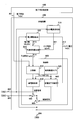
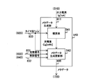
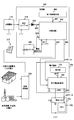
- FIG. 1 is an overall view showing one configuration example of the charging system in the first embodiment.
- the charging system includes a solar cell 110, a power outlet 210, a charger 300, and a battery pack 700.
- the battery pack 700 contains a battery in a housing, and includes a battery 710 as a battery.
- the battery 710 is a secondary battery that stores the electricity charged by the charger 300.
- the charger 300 charges the battery 710, and includes a boost converter 310, a diode 320, an AC adapter 330, a completion time setting unit 400, and a charging circuit 500.
- the solar cell 110 generates natural energy power from solar energy.
- the solar cell 110 supplies the generated natural energy power to the boost converter 310.
- the power outlet 210 supplies AC power to the AC adapter 330.
- This AC power is not natural energy power, but is commercial power generated from petroleum combustion energy and the like.
- the boost converter 310 boosts the voltage of the DC power to a constant voltage.
- boost converter 310 receives natural energy power from solar cell 110, converts the voltage into a constant voltage, and outputs the voltage to diode 320.
- the voltage to be converted is set to a voltage higher than the battery voltage Vb of the battery 710.
- the diode 320 is an element that allows current to flow only in one direction.
- the anode of diode 320 is connected to boost converter 310, and the cathode is connected to charging circuit 500. Therefore, the backflow of current from charging circuit 500 to boost converter 310 is prevented.
- the direct current power from the solar cell 110 is supplied to the charging circuit 500 via the signal line 802 via the diode 320.
- the AC adapter 330 converts AC power output from the power outlet 210 into DC power. AC adapter 330 supplies the converted DC power to charging circuit 500 via signal line 803.
- the completion time setting unit 400 sets a time at which charging of the battery 710 should be completed (hereinafter referred to as “completion time Ts”).
- the completion time Ts for example, the user inputs a time until the charging is completed with reference to the current time Tc.
- the completion time setting unit 400 acquires the current time Tc, and sets the completion time Ts by adding the input time to the current time Tc.
- the current time Tc is acquired, for example, in units of hours, minutes, and seconds.
- the set completion time Ts is output to the charging circuit 500 via the signal line 801.
- the charging circuit 500 controls the charger 300 to charge the battery 710. Specifically, charging circuit 500 determines whether charging of battery 710 is completed by completion time Ts by supplying only natural energy power to battery 710. If it is determined that the charging is completed, the charging circuit 500 charges the battery 710 only with the natural energy power. If it is determined that the process is not completed, the charging circuit 500 charges the battery 710 with the natural energy power and the power from the AC power source (ie, the power outlet 210).
- the AC power source ie, the power outlet 210
- the solar cell 110 is an example of the natural energy power supply device as described in a claim.
- the completion time setting unit 400 is an example of a setting unit described in the claims.
- the battery 710 is an example of a secondary battery described in the claims.
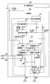
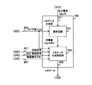
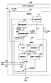
- FIG. 2 is a block diagram showing a configuration example of the charging circuit 500 in the first embodiment.
- the charging circuit 500 includes an output current measurement unit 510, a power amount acquisition unit 520, a predicted time calculation unit 530, and a control unit 600.
- the control unit 600 controls the operation of the charging circuit 500, and includes a comparison unit 610, a control cycle timer 620, a power supply control unit 630, a charge completion determination unit 640, and switches 650 and 660.
- the output current measurement unit 510 measures the value of the output current Ig output from the solar cell 110 via the signal line 802. For example, milliampere (mA) is used as a unit of measurement value.
- the output current measurement unit 510 outputs the measured value of the output current Ig to the prediction time calculation unit 530 via the signal line 811.
- the power amount acquisition unit 520 is for acquiring the power amount Q to be supplied before the charging of the battery 710 is completed. For example, milliwatt hour (mWh) is used as a unit of power amount Q. The method of acquiring the power amount Q will be described later.
- the power amount acquisition unit 520 outputs the acquired power amount Q to the predicted time calculation unit 530 via the signal line 813. Further, the power amount acquisition unit 520 measures the battery voltage Vb of the battery 710 and outputs the voltage value to the charge completion determination unit 640 via the signal line 812. As a unit of the battery voltage Vb, for example, a volt (V) is used.
- the predicted time calculation unit 530 calculates a time at which charging of the battery 710 is completed only by natural energy power (hereinafter, referred to as “predicted time Tg”).
- the predicted time Tg is calculated, for example, in seconds.
- the predicted time calculation unit 530 receives the values of the output current Ig and the power amount Q from the output current measurement unit 510 and the power amount acquisition unit 520.
- the predicted time calculation unit 530 adds the current time Tc to a value obtained by dividing the unit of the power amount Q into milliampere hours (mAh) by the output current Ig, and sets the time after addition as the predicted time Tg.
- the predicted time calculation unit 530 outputs the calculated predicted time Tg to the comparison unit 610 via the signal line 814.
- the switch 650 opens and closes a signal line between the AC adapter 330 and the battery 710 according to the control of the power supply control unit 630.
- the switch 650 closes the signal line, the power from the AC adapter 330 is supplied to the battery 710, and when the switch 650 opens the signal line, the power supply from the AC adapter 330 is cut off.
- One terminal of the switch 650 is connected to the AC adapter 330, and the other terminal is connected to the switch 660.
- the switch 660 opens and closes a signal line between the power supply (i.e., the solar cell 110 and the power outlet 210) and the battery 710 according to the control of the charge completion determination unit 640.
- the switch 660 closes the signal line to supply power from the power source to the battery 710, and the switch 660 opens the signal line to cut off the power supply to the battery 710.
- One terminal of the switch 660 is connected to the switch 650 and the diode 320, and the other terminal is connected to the battery 710.
- the comparison unit 610 compares the completion time Ts with the predicted time Tg.
- the comparison unit 610 outputs the comparison result to the feed control unit 630.
- the control cycle timer 620 counts time in the control cycle.
- the control cycle is a cycle for determining whether to switch the charging method.
- the control cycle is set to 60 seconds, and the control cycle timer 620 counts the time within the control cycle in seconds.
- the power supply control unit 630 determines whether or not to switch the charging method every control cycle, and switches the charging method based on the determination result. Specifically, the power supply control unit 630 refers to the timer value Tc of the control cycle timer 620, and refers to the comparison result of the comparison unit 610 if the timer value Tc is a predetermined value (for example, 60 seconds). If the comparison result indicates that the predicted time Tg is earlier than the completion time Ts (that is, if the charging is completed by the natural energy power only by the completion time Ts), the power supply control unit 630 causes the switch 650 Open the signal line. As a result, only the natural energy power from the solar cell 110 is supplied to the battery 710.
- the power supply control unit 630 When the comparison result indicates that the predicted time Tg is after the completion time Ts (that is, when the charging is not completed by the natural energy power alone by the completion time Ts), the power supply control unit 630 The signal line is closed at 650. As a result, the power from the solar cell 110 and the AC adapter 330 is supplied to the battery 710.
- the charge completion determination unit 640 determines whether or not charging of the battery 710 is completed at each control cycle. Specifically, the charge completion determination unit 640 refers to the timer value Tc of the control cycle timer 620, and if the timer value Tc is a predetermined value (for example, 60 seconds), the battery voltage measured by the power amount acquisition unit 520 Based on the value of Vb, it is determined whether the charging is completed. For example, if the battery voltage Vb is equal to or higher than the predetermined threshold value Vth, the charge completion determination unit 640 determines that the charge of the battery 710 is completed. If it is determined that the charging is completed, the charging completion determination unit 640 causes the switch 660 to open the signal line to end the charging. If it is determined that the charging is not completed, the charging completion determination unit 640 causes the switch 660 to close the signal line to continue the charging.
- the timer value Tc for example, 60 seconds
- the output current measurement unit 510 is an example of the output value acquisition unit described in the claims.
- FIG. 3 is a block diagram showing one configuration example of the power amount acquisition unit 520 in the first embodiment.
- the power amount acquisition unit 520 includes a battery voltage measurement unit 521, a power amount calculation unit 522, and a charging rate conversion table 523.
- the battery voltage measurement unit 521 measures the battery voltage Vb. Battery voltage measurement unit 521 outputs the measured voltage value to power amount calculation unit 522 and charge completion determination unit 640.
- the charging rate conversion table 523 associates and stores the battery voltage Vb and the charging rate R.
- the charging rate R is a ratio of the remaining capacity to the total capacity of the battery 710, and the unit is, for example, a percentage (%).
- the charging rate conversion table 523 stores the battery voltage Vb and the charging rate R, which are measured in advance, in association with each other.
- the power amount calculation unit 522 calculates the power amount Q from the battery voltage Vb. Specifically, first, the power amount calculation unit 522 reads the charging rate R corresponding to the battery voltage Vb from the charging rate conversion table 523. Then, the power amount calculation unit 522 calculates the power amount Q by substituting the read charging rate R into the following equation (1).
- Q [mWh] C [mWh] (1-R [%] / 100) (1)
- C is the full capacity of the battery 710.
- the power amount calculation unit 522 outputs the calculated power amount Q to the predicted time calculation unit 530.
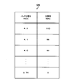
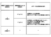
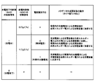
- FIG. 4 is a diagram showing an example of a configuration of the charging rate conversion table 523 in the first embodiment.
- the fully charged battery voltage Vb is 4.2 [V]
- 100 [%] as the charging rate R is stored in association with the battery voltage Vb.
- the measured value of the battery voltage Vb when discharging the capacity for 2% of the full capacity from the fully charged state is 4.1 [V]
- the battery voltage Vb has a charging rate R of 98 [%] Are stored in association with each other.
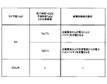
- FIG. 5 is a table showing an example of the operation of the power supply control unit 630 in the first embodiment.
- the power supply control unit 630 refers to the comparison result of the comparison unit 610. If the predicted time Tg is earlier than the completion time Ts, the power supply control unit 630 charges the battery 710 with the natural energy power from the solar cell 110. On the other hand, when the predicted time Tg is after the completion time Ts, the power supply control unit 630 charges the battery 710 only with the power from the solar cell 110 and the AC power supply (that is, the power outlet 210).
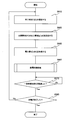
- FIG. 6 is a flowchart showing an example of the operation of the charger 300 according to the first embodiment. This operation starts when the charger 300 is connected to the solar cell 110 and the power outlet 210 and the battery pack 700 is attached to the charger 300.
- Charger 300 receives an input of the time from the current time Tc to the completion of charging.
- Completion time setting unit 400 in charger 300 sets a time obtained by adding the input time to the current time as completion time Ts in charging circuit 500 (step S 910).
- the charger 300 measures the output current Ig from the solar cell 110 (step S920), and acquires the electric energy Q based on the battery voltage Vb (step S930). Then, charger 300 executes power supply control processing to determine whether to switch the charging method (step S950).
- the charger 300 determines whether a predetermined time (for example, 60 seconds) has elapsed (step S 970). If the predetermined time has not elapsed (step S970: No), the charger 300 returns to step S970. If the predetermined time has elapsed (step S 970: Yes), the charger 300 determines whether the charging is completed (step S 980). If charging has not been completed (step S 980: No), the charger 300 returns to step S 910. If the charging is completed (step S 980: Yes), the charger 300 ends the charging.
- a predetermined time for example, 60 seconds
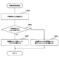
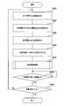
- FIG. 7 is a flowchart showing an example of the power supply control process according to the first embodiment.
- the predicted time calculation unit 530 calculates the predicted time Tg based on the electric energy Q and the output current Ig (step S953).
- Control unit 600 determines whether predicted time Tg is earlier than completion time Ts (step S956). If the predicted time Tg is earlier than the completion time Ts (step S956: Yes), the power supply control unit 630 charges the battery 710 only with the natural energy power from the solar cell 110 (step S957). If the predicted time Tg is after the completion time Ts (step S956: No), the power supply control unit 630 charges the battery 710 with the power from the solar cell 110 and the AC power supply (step S958). After step S957 or S958, the control unit 600 ends the power supply control process.
- charging circuit 500 charges battery 710 only with natural energy power based on output current Ig and power amount Q.
- the predicted time Tg at which is completed is calculated.
- the charging circuit 500 charges the battery 710 with only natural energy power.
- the battery 710 is charged only with the natural energy power, so that the natural energy power is effectively used.
- the charging circuit 500 since the charging circuit 500 is charged by the power from the AC power supply and the natural energy power when the predicted time Tg is after the completion time Ts, the charging circuit 500 completes charging by the completion time Ts.
- the charger 300 is charged by the natural energy electric power which the solar cell 110 produced
- the charger 300 may use natural energy power generated by a wind power generation device or a hydroelectric power generation device.
- the charger 300 performs constant voltage charging and measures the output current Ig from the solar cell 110
- constant current charging may be performed and the output voltage from the solar cell 110 may be measured.
- the predicted time calculation unit 530 calculates the predicted time Tg from the measured output voltage and the electric energy Q.
- the power amount acquisition unit 520 reads the charging rate R corresponding to the battery voltage Vb from the charging rate conversion table 523, it defines a relational expression indicating a relationship between the battery voltage Vb and the charging rate R Incidentally, the charging rate R can also be determined by calculation based on this relational expression.
- the power amount acquisition unit 520 calculates the power amount Q from the charging rate R
- a table in which the power amount Q calculated in advance is stored for each battery voltage Vb is used instead of the charging rate conversion table 523. It is also possible to read out the power amount Q from the table.
- the charge completion determination unit 640 determines whether the charge is completed by comparing the battery voltage Vb with the threshold value, the charge is completed by another method based on the characteristics of the battery 710. It can also be judged whether or not it has been made. For example, if the battery 710 has a characteristic that the battery voltage slightly drops when the battery reaches full charge, the charge completion determination unit 640 terminates charging when detecting the voltage drop (- ⁇ V). Can be used. Alternatively, if the battery 710 has a characteristic of generating heat when it approaches full charge, the charge completion determination unit 640 measures the temperature of the battery 710, and the temperature detection control method of terminating the charge when the temperature reaches a certain value. Can also be used.
- FIG. 8 is an overall view showing one configuration example of the charging circuit 501 in the second embodiment.
- Charging circuit 501 is based on the time from current time Tc to completion time Ts (hereinafter referred to as “remaining time Tr”) and the remaining remaining amount of battery 710 (hereinafter referred to as “remaining amount of battery Cr”). Is different from the first charging circuit 500 in that charge control is performed.
- the charging circuit 501 includes a control unit 601 instead of the control unit 600.
- the control unit 601 differs from the control unit 600 of the first embodiment in that the control unit 601 includes a power supply control unit 631 instead of the power supply control unit 630, and further includes a remaining time determination unit 670 and a battery remaining amount determination unit 680.
- the completion time setting unit 400 according to the second embodiment of the present technology outputs the completion time Ts to the remaining time determination unit 670 in addition to the comparison unit 610.
- the power amount acquisition unit 520 in the second embodiment of the present technology also outputs the measured value of the battery voltage Vb to the battery remaining amount determination unit 680.
- the remaining time determination unit 670 determines whether the remaining time Tr is equal to or longer than a predetermined set time (for example, 12 hours). Remaining time determination unit 670 outputs the determination result to power supply control unit 631.
- the battery remaining amount determination unit 680 determines whether the battery remaining amount Cr is equal to or greater than a predetermined set capacity (for example, a capacity for 10% of the total capacity).
- the unit of the battery residual amount Cr is, for example, milliwatt hour (mWh).
- the battery remaining amount determination unit 680 outputs the determination result to the power supply control unit 631.
- the power supply control unit 631 charges only natural energy power when the remaining time Tr is equal to or longer than the set time, the battery remaining amount Cr is equal to or greater than the set capacity, and the predicted time Tg is earlier than the completion time Ts. Otherwise, the power supply control unit 631 charges the battery with natural energy power and power from the AC power supply.
- FIG. 9 is a table showing an example of the operation of the power supply control unit 631 in the second embodiment.
- the power supply control unit 631 uses only the power from the solar cell 110 to To charge. If the remaining time Tr is less than the set time, or if the remaining battery capacity Cr is less than the set capacity, or if the predicted time Tg is equal to or after the completion time Ts, the power supply control unit 631 controls the solar cell 110 and the AC. The battery 710 is charged by the power from the power supply.
- FIG. 10 is a flowchart showing an example of a power supply control process according to the second embodiment.
- the feed control process in the second embodiment is different from the feed control process in the first embodiment in that steps S954 and S955 are further executed.
- the power supply control unit 631 determines whether the remaining time Tr is equal to or longer than the set time (step S954). If the remaining time Tr is equal to or longer than the set time (step S954: YES), the power supply control unit 631 determines whether the remaining battery amount Cr is equal to or higher than the set capacity (step S955). If the remaining battery amount Cr is equal to or greater than the set capacity (step S955: YES), the power supply control unit 631 determines whether the predicted time Tg is earlier than the completion time Ts (step S956).
- step S954: No If the remaining time Tr is less than the set time (step S954: No), if the remaining battery capacity Cr is less than the set capacity (step S955: No), or if the predicted time Tg is after the completion time Ts (step S95) S956: No) will be described.
- the power supply control unit 631 charges the battery 710 with the power from the solar cell 110 and the AC power supply (step S958).
- the power supply control unit 631 charges the battery 710 with the power from the solar cell 110 and the AC power supply. As a result, it is possible to prevent the charging from becoming in time until the completion time Ts.
- the power supply control unit 631 charges the battery 710 with the power from the solar cell 110 and the AC power supply. As a result, the time for charging to the set capacity is shortened, and the convenience for the user is improved.
- the charger 300 of the third embodiment is different from that of the first embodiment in that the predicted time Tg is calculated based on weather forecast data.
- the charger 300 of the third embodiment differs from the charger 300 of the first embodiment in that the completion time setting unit 402 and the charging circuit 502 are provided instead of the completion time setting unit 400 and the charging circuit 500.
- FIG. 11 is an overall view showing one configuration example of the charging circuit 502 in the third embodiment.
- the charging circuit 502 differs from the charging circuit 500 of the first embodiment in that the charging circuit 502 includes a predicted time calculation unit 531 instead of the predicted time calculation unit 530, and further includes a function acquisition unit 511 and a function table 512.
- the completion time setting unit 402 further sets weather forecast data in addition to the completion time Ts.
- the weather forecast data is information indicating the forecast period and the forecasted weather in the forecast period. For example, when it is predicted that the weather will be fine on January 1, weather forecast data indicating "January 1" as the forecasting period and "fine” as the weather is set.
- the completion time setting unit 402 outputs the set weather forecast data to the function acquisition unit 511 via the signal line 805.
- the function table 512 stores, for each weather, a function indicating the characteristic of the predicted output current Ig. Since the amount of power generation of the solar cell 110 increases or decreases according to the amount of sunlight, the value of the output current Ig generally rises with the passage of time from early morning to daytime, and over time from daytime to evening It decreases with it. Based on the characteristics of the output current Ig, it is possible to approximate changes in the time series of the value of the predicted output current Ig to a function (for example, a quadratic function) of time t. In addition, the amount of sunlight varies according to the weather. Therefore, different functions are defined for each weather and stored in the function table 512.
- the function acquisition unit 511 acquires a function Ig (t) corresponding to the weather. Specifically, when receiving the weather forecast data, the function obtaining unit 511 reads out the function Ig (t) corresponding to the weather indicated by the weather forecast data from the function table 512 via the signal line 915. The function acquisition unit 511 outputs the read function Ig (t) and the forecast period indicated by the weather forecast data to the forecasted time calculation unit 531 through the signal line 916.
- the predicted time calculation unit 531 calculates the predicted time Tg from the function Ig (t). Specifically, the predicted time calculation unit 531 calculates a time t at which a value obtained by converting an integrated value of Ig (t) in the period from the current time Tc to the elapse of the forecast period equals the power amount Q becomes equal to the power amount Q. Do.
- the predicted time calculation unit 531 outputs the integrated value of the function Ig (t) until the forecast period elapses and the output after the forecast period elapses A time t in which the amount of power corresponding to the addition value with the integral value of the current Ig becomes equal to the amount of power Q is calculated.
- the predicted time calculation unit 531 sets a value obtained by adding the calculated time t to the current time Tc as a predicted time Tg.
- the predicted time calculation unit 531 calculates the predicted time Tg from the measured output current Ig.
- the function acquisition unit 511 is an example of a predicted value acquisition unit described in the claims.
- the function table 512 is an example of a predicted value storage unit described in the claims.
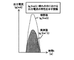
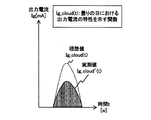
- 12A to 12C are graphs showing an example of a function showing characteristics of the output current in the third embodiment.
- a function indicated by a dotted line is a function indicating a change in predicted value of the output current Ig in an ideal environment.
- the function shown by a solid line is a function that approximates the change of the actually measured output current Ig. Since the power generation amount of the solar cell 110 varies depending on the area and the installation environment, the actual measurement value is often different from the ideal value. If the actual value is not obtained, the function based on the ideal value is stored in the function table 512. If the actual value is obtained, the function indicated by the dotted line is stored in the function table 512 with the function corrected based on the actual value. Be done.
- FIG. 12A is an example of a function showing the characteristics of the output current Ig on a sunny day
- FIG. 12B is an example of a function showing the characteristics of the output current Ig on a cloudy day
- FIG. 12C is an example of a function indicating the characteristics of the output current Ig on a rainy day.
- FIG. 13 is a table showing an example of the operation of the charger 300 in the third embodiment.
- the operation of the charger 300 according to the third embodiment is different from the operation of the charger 300 according to the first embodiment in that step S940 is further performed.
- the charger 300 acquires the electric energy Q (step S930), and receives the input of the weather forecast data.
- the completion time setting unit 402 sets the weather forecast data in the charging circuit 502 (step S940). Then, charger 300 executes the power supply control process (step S950).
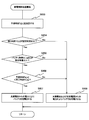
- FIG. 14 is a flowchart showing an example of power supply control processing in the third embodiment.
- the feed control process of the third embodiment is different from the feed control process of the first embodiment in that steps S951 and S952 are further executed.
- the charging circuit 502 determines whether weather forecast data has been acquired (step S951). If the weather forecast data is acquired (step S 951: Yes), the predicted time calculation unit 531 calculates the predicted time Tg based on the function Ig (t) corresponding to the weather indicated by the weather forecast data (Ste S952). If the weather forecast data is not acquired (step S951: No), the predicted time calculation unit 531 calculates the predicted time Tg based on the measured output current Ig (step S953). After step S952 or S953, the control unit 600 determines whether the predicted time Tg is earlier than the completion time Ts (step S956).
- the charging circuit 502 when the weather forecast data is set, the charging circuit 502 reads out the predicted value corresponding to the weather indicated by the weather forecast data from the function table 512.
- the predicted time Tg is calculated based on the predicted value and the power amount Q.
- the charging circuit 502 can calculate the predicted time Tg more accurately, based on the fluctuation of the natural energy power associated with the weather.
- the weather forecast data is configured to be input by the user, it may be configured to acquire the weather forecast data by the charger 300 performing wireless or wired communication.
- the charging circuit 502 is configured to store the function of the output current Ig for each weather, the predicted value that is not a function may be stored for each weather.
- the charging circuit 502 can store the average value and the median value of the output current Ig for each weather.
- the charging circuit 502 is configured to include both the function acquisition unit 511, the function table 512, and the output current measurement unit 510. However, the charging circuit 502 may be configured to include only one of the function acquisition unit 511, the function table 512, and the output current measurement unit 510.
- the charging system of the fourth embodiment is different from the charging system of the first embodiment in that the charging capacity by natural energy power and the charging capacity by power other than natural energy power are stored.
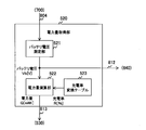
- FIG. 15 is an overall view showing one configuration example of the charging system in the fourth embodiment.
- the charging system of the fourth embodiment is different from the charging system of the first embodiment in that a charger 303 and a battery pack 703 are provided instead of the charger 300 and the battery pack 700.
- the charger 303 is different from the charging circuit 500 of the first embodiment in that the charging circuit 503 is provided instead of the charging circuit 500.
- Battery pack 703 differs from battery pack 700 of the first embodiment in that it further includes memory 720.
- the charging circuit 503 generates, as metadata, information indicating a charging capacity by natural energy power and a charging capacity by power other than natural energy power.
- the charging circuit 503 outputs the metadata to the memory 720 via the signal line 806.
- the memory 720 is for storing metadata.
- the metadata stored in the memory 720 is read by the electronic device 750 powered by the battery pack 703.
- the electronic device 750 reads metadata from the memory 720, and displays the charging capacity by natural energy power and the charging capacity by power other than natural energy power based on the metadata.
- the metadata is an example of charging data described in the claims.
- the memory 720 is an example of a charge data storage unit described in the claims.
- the electronic device 750 is an example of the display portion described in the claims.
- FIG. 16 is a block diagram showing a configuration example of the charging circuit 503 in the fourth embodiment.
- the charging circuit 503 is different from the charging circuit 500 of the first embodiment in that the charging circuit 503 further includes a metadata generation unit 540.
- the metadata generation unit 540 generates and outputs metadata.
- the metadata generation unit 540 acquires a switching signal for controlling the switch 650 from the power supply control unit 630 via the signal line 831. For example, a value of “1” is set to the switching signal when the switch 650 is to close the signal line, and a value of “0” is set to open the circuit.
- the metadata generation unit 540 acquires a control signal for controlling the switch 660 from the charge completion determination unit 640 via the signal line 832. For example, a value of “1” is set to the control signal when the switch 660 closes the signal line, and a value of “0” is set to open the circuit.
- the metadata generation unit 540 acquires the measurement value of the output current Ig from the output current measurement unit 510, and acquires the timer value Tc via the signal line 833. Then, the metadata generation unit 540 adds a value obtained by integrating the timer value Tc to the measured value of the output current Ig when charging by the power from the solar cell 110 to the charging capacity by the natural energy power. In addition, when charging with power from the AC power supply, the metadata generation unit 540 adds a value obtained by integrating the timer value Tc to the output current of the AC adapter 330 to the charging capacity of power other than natural energy power. The metadata generation unit 540 generates metadata indicating each charge capacity and outputs the metadata to the memory 720.
- the metadata generation unit 540 is an example of a charge data generation unit described in the claims.
- FIG. 17 is a block diagram showing an exemplary configuration of the metadata generation unit 540 in the fourth embodiment.
- the metadata generation unit 540 includes an integration unit 541 and a metadata generation and update unit 542.
- the integration unit 541 calculates a charge amount Cg which is a value obtained by converting an integrated value of the output current Ig in the control cycle into an electric energy.
- the unit of the charge amount Cg is, for example, milliwatt hour (mWh).
- the integration unit 541 outputs the charge amount Cg to the metadata generation and update unit 542.
- the metadata generation and update unit 542 generates and updates metadata.
- the case where the switch 660 closes the signal line and the switch 650 opens the signal line (that is, the case where charging is performed only by the power from the solar cell 110) will be described.
- the metadata generation and update unit 542 adds the charge amount Cg to the charge capacity of the natural energy power.
- the case where switches 660 and 650 both close the signal line (that is, when charging by the power from solar cell 110 and AC power supply) will be described.
- the metadata generation and update unit 542 adds the charge amount Cg to the charge capacity by natural energy power, and integrates the output current of the AC adapter 330 in the control cycle into a charge capacity by power other than natural energy power.
- the metadata generation and update unit 542 generates and outputs information indicating the charge capacity as metadata. After generating the metadata, the metadata generation and update unit 542 updates each charge capacity in the metadata in the memory 720 as the timer value Tc increases. When the switch 660 opens the signal line (that is, when the charging is completed), the metadata generation and update unit 542 ends the metadata update.
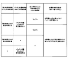
- FIG. 18 is a table showing an example of the operation of the metadata generation / updating unit 542 in the fourth embodiment.
- the case where the value of the control signal of the charge completion determination unit 640 is “1” and the value of the switching signal of the power supply control unit 630 is “0” will be described.
- the metadata generation and update unit 542 adds the charge capacity of the solar cell 110 (that is, the charge amount Cg) to the charge capacity of the natural energy power.
- the metadata generation / updating unit 542 adds the charge capacity of the solar cell 110 to the charge capacity of natural energy power, and adds the charge capacity of the AC power source to the charge capacity of power other than natural energy power.
- the metadata generation and update unit 542 ends the metadata update.
- FIG. 19 is a flow chart showing an example of the operation of the charger 303 in the fourth embodiment.
- the operation of the charger 303 is different from the operation of the charger 300 of the first embodiment in that the step S960 is further performed.
- the charger 303 executes power supply control processing (step S950), generates and updates metadata (step S960). Then, the charger 303 determines whether a predetermined time has elapsed (step S 970).
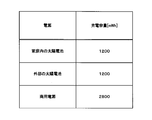
- FIG. 20 is a diagram showing an exemplary configuration of metadata in the fourth embodiment.
- the metadata includes an area 551 for storing a charge capacity by natural energy power and an area 552 for storing a charge capacity by power other than the natural energy power. For example, when the capacity of 4800 [mWh] is charged by natural energy power and the capacity of 2800 [mWh] is charged by power other than natural energy power, data indicating “4800” is stored in area 551, and Stores data indicating "2800".
- FIG. 21 is a display example of contents indicated by metadata in the fourth embodiment.
- the electronic device 750 displays the charging capacity by natural energy power and the charging capacity by power other than the natural energy power so that the user can easily identify. For example, the electronic device 750 displays the total capacity of the battery with a single bar, and displays in black the portion of the length obtained by multiplying the natural energy power charging rate by the total length of the bar. In addition, the electronic device 750 displays in gray the part of the length obtained by multiplying the charging rate by the power that is not the natural energy power by the total length of the bar in gray and the remaining part in white.
- the charging circuit 503 outputs metadata indicating a charging capacity by natural energy power and a charging capacity by power other than natural energy power.
- the electronic device 750 can display each charge capacity. The display of the charge capacity for each power supply allows the user to easily grasp how much natural energy power has been used in charging.
- metadata is stored in the memory 720 in the battery pack 703. Therefore, even if the device is an external device of the charger 303, each charging capacity can be acquired as long as the battery pack 703 can be attached.
- the charger 303 may further include a display unit configured to display the content indicated by the metadata.
- the charging system of the fifth embodiment differs from the charging system of the fourth embodiment in that the source of AC power is acquired to generate metadata.
- FIG. 22 is an overall view showing one configuration example of the charging system in the fifth embodiment.
- the charging system according to the fifth embodiment is different from the charging system according to the fourth embodiment in that the charging system further includes a conversion switching unit 220, and includes a charger 304 instead of the charger 303.
- the conversion switching unit 220 receives commercial power and natural energy power from a commercial power source and a natural energy power source, and supplies either of them to the power outlet 210.
- the natural energy power source is, for example, an external solar power generation device having a different installation place from the solar battery 110. Further, the conversion switching unit 220 superimposes the power supply identifier ID on the AC waveform of the supplied AC power using a PLC (Power Line Communications) module or the like.
- the power supply identifier ID is an identifier for identifying an AC power supply source. For example, a value of “0” is set to the power supply identifier ID when AC power is supplied from a commercial power supply, and a value of “1” is set to power supply identifier ID when supplied from a natural energy power supply.
- the charger 304 differs from the charger 303 of the fourth embodiment in that the AC adapter 340 and the charging circuit 504 are provided instead of the AC adapter 330 and the charging circuit 503.
- the AC adapter 340 separates the power supply identifier ID from the AC waveform of the received AC power.
- the AC adapter 340 converts the AC power into DC power and supplies the DC power via the signal line 803 to the charging circuit 504, and outputs the power supply identifier ID to the charging circuit 504 via the signal line 807.
- the charging circuit 504 When charging with AC power, the charging circuit 504 updates the value of the charging capacity corresponding to the supply source indicated by the power supply identifier ID in the metadata.
- the AC adapter 340 is an example of the separation unit described in the claims.
- the power supply identifier ID is an example of a power supply identification signal described in the claims.
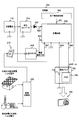
- FIG. 23 is a block diagram showing a configuration example of the conversion switching unit 220 in the fifth embodiment.
- the conversion switching unit 220 includes an inverter 221, a switching control unit 222, power supply identifier superposition units 223 and 224, a power supply identifier storage unit 225, and a switch 226.
- the inverter 221 converts DC power supplied from a natural energy power source into AC power.
- the inverter 221 outputs the converted AC power to the power supply identifier superposition unit 223.
- the switching control unit 222 performs control of switching the AC power supply source. Specifically, the switching control unit 222 monitors the amount of power generation of natural energy power, and controls the switch 226 based on the amount of power generation. For example, the switching control unit 222 switches the AC power supply source to the natural energy power source when the power generation amount of the natural energy power is equal to or greater than the threshold value, and switches the power source to the commercial power source when the power generation amount is less than the threshold value.
- the power supply identifier superposition unit 223 acquires the power supply identifier ID corresponding to the natural energy power supply from the power supply identifier storage unit 225, and superimposes the power supply identifier ID on the AC waveform of the AC power supplied from the inverter 221.
- the AC power in which the power supply identifier ID is superimposed on the AC waveform is output to the input terminal of the switch 226.
- the power supply identifier superposition unit 224 acquires the power supply identifier ID corresponding to the commercial power supply from the power supply identifier storage unit 225, and superimposes the power supply identifier ID on the AC waveform of the AC power supplied from the commercial power supply.
- the AC power in which the power supply identifier ID is superimposed on the AC waveform is output to the input terminal of the switch 226.
- the power source identifier storage unit 225 stores a power source identifier ID for each power source.
- the switch 226 switches the AC power supply source according to the control of the switching control unit 222.
- the switch 226 has two input terminals and one output terminal. One input terminal is connected to the power supply identifier superposition unit 223, and the other input terminal is connected to the power supply identifier superposition unit 224.
- the output terminal is connected to the power outlet 210 via a transformer or the like.
- FIG. 24 is a block diagram showing a configuration example of the metadata generation unit 545 in the fifth embodiment.
- the metadata generation unit 545 of the fifth embodiment differs from the metadata generation unit 540 of the fourth embodiment in that a metadata generation and update unit 543 is provided instead of the metadata generation and update unit 542.
- the metadata generation and update unit 543 receives the power supply identifier ID from the AC adapter 340 in addition to the switching signal and the control signal from the power supply control unit 630 and the charge completion determination unit 640.
- the metadata generation and update unit 543 identifies the AC power supply source with reference to the power supply identifier ID when the battery 710 is charged by the power from the solar cell 110 and the AC power supply.
- the metadata generation and update unit 543 adds the charging capacity by the AC power supply and the power from the solar cell 110 in the home to the charging capacity by the natural energy power.
- the commercial power source is a supply source of AC power
- the metadata generation and update unit 543 adds the charge capacity of the solar cell 110 to the charge capacity of natural energy power, and the charge capacity of the AC power source is power of other than natural energy Add to the charge capacity.
- FIG. 25 is a table showing an example of the operation of the metadata generation and update unit 543 in the fifth embodiment.
- the case where the value of the control signal of the charge completion determination unit 640 and the value of the switching signal of the power supply control unit 630 are both “1” and the power supply identifier ID is “0” will be described.
- the metadata generation and update unit 543 adds the charge capacity of the solar cell 110 to the charge capacity of natural energy power, and adds the charge capacity of the AC power supply to the charge capacity of power other than natural energy power.
- each value of the switching signal and the control signal is “1” and the power supply identifier ID is “1” will be described.
- the electric power from the solar cell 110 in the home and the electric power from the external solar cell are supplied to the battery 710. Therefore, the metadata generation and update unit 543 adds the charge capacity of the solar cell 110 and the AC power supply in the home to the charge capacity of the natural energy power.
- the charging circuit 504 acquires the power supply identifier ID, and generates metadata based on the power supply identifier ID. Thereby, even if there are a plurality of AC power supply sources, the charge capacity can be calculated for each supply source.
- the conversion switching unit 220 superimposes a power supply identifier ID for identifying whether or not the supply source is a natural energy power supply, even if an identifier for identifying the type of natural energy power supply is superimposed. Good.
- the conversion switching unit 220 may superimpose a power supply identifier for identifying each power supply such as a hydroelectric power generation device, a solar power generation device, or a geothermal power generation device.
- the charger 304 calculates the charging capacity by the natural energy power and the charging capacity by the power other than the natural energy power
- the charging capacity may be calculated for each supply source of the natural energy power.
- the charger 304 calculates the charging capacity by the solar cell 110 in the home, the charging capacity by the external solar cell, and the charging capacity by the commercial power source.
- the charger 304 generates metadata indicating each charge capacity as shown in FIG.
- the metadata a plurality of areas for storing information indicating the power supply and an area for storing information indicating the charge capacity are provided in association with each other.
- the conversion switching unit 220 superimposes the power supply identifier ID on both of the AC power from the commercial power supply and the AC power from the natural energy power supply, it may be superimposed on only one of them.
- FIG. 27 is an overall view showing one configuration example of the charging system in the sixth embodiment.
- the charging system in the sixth embodiment differs from the charging system in the fifth embodiment in that the electronic device 751 is further provided.
- the electronic device 751 is a device using the battery pack 703 as a power source, and includes an electronic device control unit 760 and a display unit 770.
- the electronic device control unit 760 controls the entire electronic device 751.
- the electronic device control unit 760 receives DC power from the charger 304 via the signal line 804, and receives metadata via the signal line 806.
- the electronic device control unit 760 outputs the received DC power to the battery 710 via the signal line 808, and outputs the metadata to the memory 720 via the signal line 809.
- the electronic device control unit 760 reads the metadata from the memory 720 and causes the display unit 770 to display the content indicated by the metadata.
- the display unit 770 displays the content indicated by the metadata.
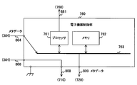
- FIG. 28 is a block diagram showing a configuration example of the electronic device control unit 760 in the sixth embodiment.
- the electronic device control unit 760 includes a processor 761, a memory 762, and a bus 763.
- the processor 761 controls the entire electronic device 751.
- the processor 761 outputs the metadata received from the charger 304 to the battery pack 703.
- the processor 761 also reads the metadata stored in the battery pack 703, generates data for displaying the content indicated by the metadata, and outputs the data to the display unit 770 via the signal line 881.
- the memory 762 is a main storage directly accessible by the processor 761.
- the bus 763 is a common path for the processor 761 and the memory 762 to transmit and receive data.
- the charger 304 charges the battery pack 703 via the electronic device 751.
- the charger 304 can charge the battery pack 703 with the battery pack 703 attached to the electronic device 751, and the convenience of the user is improved.
- the memory 720 is provided in the battery pack 703, the memory 720 may be provided not in the battery pack 703 but in the electronic device 751. This eliminates the need for providing the memory 720 in the battery pack 703.
- FIG. 29 is a block diagram showing one configuration example of the charging circuit 506 of the modification.
- the charging circuit 506 is different from the charging circuit 500 of the first embodiment in that a control unit 606 is provided instead of the control unit 600.
- the control unit 606 is different from the control unit 600 of the first embodiment in that a switch 651 is provided instead of the switch 650.
- the switch 651 has two input terminals and one output terminal. One input terminal of the switch 651 is connected to the diode 320, and the other input terminal is connected to the AC adapter 330. The output terminal of the switch 651 is connected to the switch 660.
- the feed control unit 630 switches the input destination of the switch 651 to the diode 320 when the predicted time Tg is earlier than the completion time Ts, and switches the input destination of the switch 651 to the AC adapter 330 when the predicted time Tg is later than the completion time Ts. Switch to Thus, when predicted time Tg is after completion time Ts, battery 710 is charged only with AC power. According to this configuration, only either one of the natural energy power and the power from the AC power source is supplied, and therefore overcharging may occur compared to the charger system of the first embodiment that supplies both. Becomes lower.
- the processing procedure described in the above-described embodiment may be regarded as a method having a series of these procedures, and a program for causing a computer to execute the series of procedures or a recording medium storing the program. You may catch it.
- a recording medium for example, a CD (Compact Disc), an MD (Mini Disc), a DVD (Digital Versatile Disc), a memory card, a Blu-ray Disc (registered trademark), or the like can be used.
- the present technology can also be configured as follows.
- An output value acquisition unit that acquires an output value of voltage or current from a natural energy power supply device that is a power supply device that generates natural energy power from natural energy;
- An electric energy acquisition unit for acquiring an electric energy to be supplied before charging of the secondary battery is completed, and charging of the secondary battery is completed only by the natural energy electric power based on the output value and the electric energy
- a predicted time calculation unit that calculates the time of day as the predicted time;
- the control unit charges the secondary battery with power generated by a power supply device other than the natural energy power supply device, when the predicted time is after the completion time.
- the control unit further supplies the natural energy power to charge the secondary battery when the predicted time is after the completion time.
- the setting unit further sets weather forecast data indicating weather.
- the output value acquisition unit predicts the output value for each weather based on the set weather forecast data,
- the predicted time calculation unit calculates the predicted time based on the output value and the power amount for each predicted weather.
- a charge data generation unit for generating and outputting information indicating charge capacity of the secondary battery by the natural energy power and charge capacity of the secondary battery by the power other than the natural energy power as charge data Equipped
- the charger according to any one of the above (2) to (4).
- the power supply apparatus other than the natural energy power supply apparatus receives AC power in which a power supply identification signal for identifying a power supply source is superimposed on an AC waveform, and separates the power supply identification signal from the AC waveform Further equipped with a separation unit, The charge data generation unit generates the charge data based on the separated power supply identification signal.
- the charger according to (5).
- the control unit charges the secondary battery only with the natural energy power when the remaining time which is the time from the current time to the completion time is equal to or longer than a predetermined time.
- the control unit charges the secondary battery only with the natural energy power when the remaining capacity of the secondary battery is equal to or greater than a predetermined capacity.
- the setting unit further sets weather forecast data indicating the weather,
- the output value acquisition unit predicts the output value for each weather based on the set weather forecast data,
- the predicted time calculation unit calculates the predicted time based on the output value and the power amount for each predicted weather.
- a predicted time calculation unit that calculates a time when charging of the secondary battery is completed as a predicted time; and charging the secondary battery with only the natural energy power if the predicted time is earlier than the completion time, the prediction
- a charger and a charging capacity and the charging data generation unit for generating and outputting a charging data information indicating the charge capacity of the secondary battery by the electric power other than the natural energy power of the secondary battery according to the energy power,
- the power supply apparatus other than the natural energy power supply apparatus receives AC power in which a power supply identification signal for identifying a power supply source is superimposed on an AC waveform
- the charger further includes a separation unit that separates the power supply identification signal from the AC waveform, and the charge data generation unit generates the charge data based on the separated power supply identification signal.
- the display device is further provided with a display unit that displays the charge capacity of the secondary battery with the natural energy power and the charge capacity of the secondary battery with power other than the natural energy power based on the charge data.
- the charging system according to (10) or (11).
- (13) a setting procedure for setting a completion time which is a time at which charging of the secondary battery should be completed;
- An output value acquisition procedure for acquiring an output value of voltage or current from a natural energy power supply device that is a power supply device generating natural energy power from natural energy;
- the charging of the secondary battery is completed only by the natural energy power based on an electric energy acquisition procedure for acquiring an electric energy to be supplied before the charging of the secondary battery is completed, the output value and the electric energy
Abstract
Description
1.第1の実施の形態(充電制御:完了時刻と予測時刻とを比較する例)
2.第2の実施の形態(充電制御:残り時間およびバッテリ残量を監視する例)
3.第3の実施の形態(充電制御:天候予報データを利用する例)
4.第4の実施の形態(充電制御:メタデータを生成する例)
5.第5の実施の形態(充電制御:電源識別子を取得する例)
6.第6の実施の形態(充電制御:電子機器を経由して充電する例)
7.変形例 Hereinafter, a mode for carrying out the present technology (hereinafter, referred to as an embodiment) will be described. The description will be made in the following order.
1. First Embodiment (Charging Control: Example of Comparing Completion Time and Estimated Time)
2. Second Embodiment (Charging Control: Example of Monitoring Remaining Time and Remaining Battery)
3. Third embodiment (charge control: an example using weather forecast data)
4. Fourth Embodiment (Charging Control: Example of Generating Metadata)
5. Fifth Embodiment (Charging Control: Example of Obtaining a Power Supply Identifier)
6. Sixth embodiment (charge control: an example of charging via an electronic device)
7. Modified example
[充電システムの構成例]
図1は、第1の実施の形態における充電システムの一構成例を示す全体図である。充電システムは、太陽電池110、電源コンセント210、充電器300、および、電池パック700を備える。電池パック700は、電池を筐体に収めたものであり、電池としてバッテリ710を備える。バッテリ710は、充電器300により充電された電気を蓄える2次電池である。充電器300は、バッテリ710を充電するものであり、昇圧コンバータ310、ダイオード320、交流アダプタ330、完了時刻設定部400、および、充電回路500を備える。 <1. First embodiment>
[Example of configuration of charging system]
FIG. 1 is an overall view showing one configuration example of the charging system in the first embodiment. The charging system includes a
図2は、第1の実施の形態における充電回路500の一構成例を示すブロック図である。充電回路500は、出力電流測定部510、電力量取得部520、予測時刻算出部530、および、制御部600を備える。制御部600は、充電回路500の動作を制御するものであり、比較部610と、制御周期タイマ620と、給電制御部630と、充電完了判断部640と、スイッチ650および660とを備える。 [Example of configuration of charging circuit]
FIG. 2 is a block diagram showing a configuration example of the charging
The power
Q[mWh]=C[mWh](1-R[%]/100)・・・(1) The power
Q [mWh] = C [mWh] (1-R [%] / 100) (1)
図5~図7を参照して、充電器300の動作例について説明する。図5は、第1の実施の形態における給電制御部630の動作の一例を示す表である。タイマ値Tcが60秒であった場合、給電制御部630は、比較部610の比較結果を参照する。予測時刻Tgが完了時刻Tsより早い場合には、給電制御部630は、太陽電池110からの自然エネルギー電力によりバッテリ710を充電させる。一方、予測時刻Tgが完了時刻Ts以降である場合には、給電制御部630は、太陽電池110および交流電源(すなわち、電源コンセント210)からの電力のみによりバッテリ710を充電させる。 [Operation example of charger]
An operation example of the
[充電回路の構成例]
次に、図8~図10を参照して、本技術の第2の実施の形態について説明する。図8は、第2の実施の形態における充電回路501の一構成例を示す全体図である。充電回路501は、現在時刻Tcから完了時刻Tsまでの時間(以下、「残り時間Tr」と称する。)とバッテリ710の残存残量(以下、「バッテリ残量Cr」と称する。)とに基づいて充電制御を行う点において第1の充電回路500と異なる。充電回路501は、制御部600の代わりに制御部601を備える。制御部601は、給電制御部630の代わりに給電制御部631を備え、残り時間判断部670およびバッテリ残量判断部680をさらに備える点において第1の実施の形態の制御部600と異なる。本技術の第2の実施の形態における完了時刻設定部400は、比較部610のほか、残り時間判断部670にも完了時刻Tsを出力する。また、本技術の第2の実施の形態における電力量取得部520は充電完了判断部640のほか、バッテリ残量判断部680にも、バッテリ電圧Vbの測定値を出力する。 <2. Second embodiment>
[Example of configuration of charging circuit]
Next, with reference to FIGS. 8 to 10, a second embodiment of the present technology will be described. FIG. 8 is an overall view showing one configuration example of the charging
図9および図10を参照して、第2の実施の形態における充電器300の動作例について説明する。図9は、第2の実施の形態における給電制御部631の動作の一例を示す表である。残り時間Trが設定時間以上であり、バッテリ残量Crが設定容量以上であり、かつ、予測時刻Tgが完了時刻Tsより早い場合に、給電制御部631は太陽電池110からの電力のみによりバッテリ710を充電させる。残り時間Trが設定時間未満である場合、または、バッテリ残量Crが設定容量未満である場合、あるいは、予測時刻Tgが完了時刻Ts以降である場合に、給電制御部631は太陽電池110および交流電源からの電力によりバッテリ710を充電させる。 [Operation example of charger]
An operation example of the
[充電回路の構成例]
次に、図11~図14を参照して、本技術の第3の実施の形態について説明する。第3の実施の形態の充電器300は、天候予報データに基づいて予測時刻Tgを算出する点において第1の実施の形態と異なる。第3の実施形態の充電器300は、完了時刻設定部400および充電回路500の代わりに完了時刻設定部402および充電回路502を備える点において、第1の実施の形態の充電器300と異なる。 <3. Third embodiment>
[Example of configuration of charging circuit]
Next, a third embodiment of the present technology will be described with reference to FIG. 11 to FIG. The
図13および図14を参照して、第3の実施の形態における充電器300の動作例について説明する。図13は、第3の実施の形態における充電器300の動作の一例を示す表である。第3の実施の形態の充電器300の動作は、ステップS940をさらに実施する点において第1の実施の形態の充電器300の動作と異なる。充電器300は、電力量Qを取得し(ステップS930)、天候予報データの入力を受け付ける。天候予報データが入力されると、完了時刻設定部402は、その天候予報データを充電回路502に設定する(ステップS940)。そして、充電器300は、給電制御処理を実行する(ステップS950)。 [Operation example of charger]
An operation example of the
[充電システムの構成例]
次に、図15~図21を参照して、本技術の第4の実施の形態について説明する。第4の実施の形態の充電システムは、自然エネルギー電力による充電容量と、自然エネルギー電力以外の電力による充電容量とを記憶する点において第1の実施形態の充電システムと異なる。 <4. Fourth embodiment>
[Example of configuration of charging system]
Next, a fourth embodiment of the present technology will be described with reference to FIGS. 15 to 21. The charging system of the fourth embodiment is different from the charging system of the first embodiment in that the charging capacity by natural energy power and the charging capacity by power other than natural energy power are stored.
図16は、第4の実施の形態における充電回路503の一構成例を示すブロック図である。充電回路503は、メタデータ生成部540をさらに備える点において第1の実施の形態の充電回路500と異なる。 [Example of configuration of charging circuit]
FIG. 16 is a block diagram showing a configuration example of the charging
図18および図19を参照して、第4の実施の形態における充電器303の動作例について説明する。図18は、第4の実施の形態におけるメタデータ生成更新部542の動作の一例を示す表である。充電完了判断部640の制御信号の値が「1」であり、給電制御部630の切替信号の値が「0」である場合について説明する。この場合においては、予測時間Tgが完了時間Tsより早いため、太陽電池110からの電力のみによりバッテリ710が充電されている。このため、メタデータ生成更新部542は、太陽電池110による充電容量(すなわち、充電量Cg)を自然エネルギー電力による充電容量に加算する。一方、切替信号および制御信号の値がいずれも「1」である場合について説明する。この場合においては、予測時間Tgが完了時間Ts以降であるため、太陽電池110および交流電源からの電力によりバッテリ710が充電されている。このため、メタデータ生成更新部542は、太陽電池110による充電容量を自然エネルギー電力による充電容量に加算し、交流電源による充電容量を、自然エネルギー電力以外の電力による充電容量に加算する。充電完了判断部640の制御信号の値が「0」である場合(すなわち、充電が完了した場合)、メタデータ生成更新部542は、メタデータの更新を終了する。 [Operation example of charger]
An operation example of the
[充電システムの構成例]
次に、図22~図26を参照して、本技術の第5の実施の形態について説明する。第5の実施の形態の充電システムは、交流電力の供給源を取得してメタデータを生成する点において第4の実施形態の充電システムと異なる。 <5. Fifth embodiment>
[Example of configuration of charging system]
Next, a fifth embodiment of the present technology will be described with reference to FIGS. 22 to 26. The charging system of the fifth embodiment differs from the charging system of the fourth embodiment in that the source of AC power is acquired to generate metadata.
図25を参照して、第5の実施の形態における充電器304の動作例について説明する。図25は、第5の実施の形態におけるメタデータ生成更新部543の動作の一例を示す表である。充電完了判断部640の制御信号の値と、給電制御部630の切替信号の値とがいずれも「1」であり、かつ、電源識別子IDが「0」である場合について説明する。この場合、太陽電池110および商用電源からの電力がバッテリ710に供給されている。このため、メタデータ生成更新部543は、太陽電池110による充電容量を自然エネルギー電力による充電容量に加算し、交流電源による充電容量を自然エネルギー電力以外の電力による充電容量に加算する。 [Operation example of charger]
An operation example of the
As described above, according to the fifth embodiment of the present technology, the charging
[充電システムの構成例]
次に、図27および図28を参照して、本技術の第6の実施の形態について説明する。第6の実施の形態における充電システムは、電子機器を経由して充電を行う点において第5の実施の形態の充電システムと異なる。 <6. Sixth embodiment>
[Example of configuration of charging system]
Next, a sixth embodiment of the present technology will be described with reference to FIGS. 27 and 28. The charging system in the sixth embodiment differs from the charging system of the fifth embodiment in that charging is performed via an electronic device.
[充電回路の構成例]
次に、図29を参照して、本技術の変形例について説明する。図29は、変形例の充電回路506の一構成例を示すブロック図である。充電回路506は、制御部600の代わりに制御部606を備える点において、第1の実施の形態の充電回路500と異なる。制御部606は、スイッチ650の代わりにスイッチ651を備える点において第1の実施の形態の制御部600と異なる。 <7. Modified example>
[Example of configuration of charging circuit]
Next, a modification of the present technology will be described with reference to FIG. FIG. 29 is a block diagram showing one configuration example of the charging
(1)2次電池の充電を完了すべき時刻である完了時刻を設定する設定部と、
自然エネルギーから自然エネルギー電力を生成する電源装置である自然エネルギー電源装置からの電圧または電流の出力値を取得する出力値取得部と、
前記2次電池の充電が完了するまでに供給すべき電力量を取得する電力量取得部と、前記出力値と前記電力量とに基づいて前記自然エネルギー電力のみにより前記2次電池の充電が完了する時刻を予測時刻として算出する予測時刻算出部と、
前記予測時刻が前記完了時刻より早い場合には前記自然エネルギー電力のみにより前記2次電池を充電させる制御部と、
を具備する、充電器。
(2)前記制御部は、前記予測時刻が前記完了時刻以降である場合には前記自然エネルギー電源装置以外の電源装置が生成した電力により前記2次電池を充電させる、
前記(1)に記載の充電器。
(3)前記制御部は、前記予測時刻が前記完了時刻以降である場合には前記自然エネルギー電力をさらに供給して前記2次電池を充電させる、
前記(2)に記載の充電器。
(4)前記設定部は、天候を示す天候予報データをさらに設定し、
前記出力値取得部は、前記設定された天候予報データに基づいて前記出力値を天候ごとに予測し、
前記予測時刻算出部は、前記予測された天候ごとの前記出力値および前記電力量に基づいて前記予測時刻を算出する、
前記(3)記載の充電器。
(5)前記自然エネルギー電力による前記2次電池の充電容量と前記自然エネルギー電力以外の電力による前記2次電池の充電容量とを示す情報を充電データとして生成して出力する充電データ生成部をさらに具備する、
前記(2)~(4)のいずれかに記載の充電器。
(6)前記自然エネルギー電源装置以外の電源装置は、電力の供給源を識別するための電源識別信号が交流波形に重畳された交流電力を受電し、前記交流波形から前記電源識別信号を分離する分離部をさらに具備し、
前記充電データ生成部は、前記分離された電源識別信号に基づいて前記充電データを生成する、
前記(5)に記載の充電器。
(7)前記制御部は、現在時刻から前記完了時刻までの時間である残り時間が所定の時間以上である場合には前記自然エネルギー電力のみにより前記2次電池を充電させる、
前記(1)~(6)のいずれかに記載の充電器。
(8)前記制御部は、前記2次電池の残存容量が所定の容量以上である場合には前記自然エネルギー電力のみにより前記2次電池を充電させる、
前記(1)~(7)のいずれかに記載の充電器。
(9)前記設定部は、天候を示す天候予報データをさらに設定し、
前記出力値取得部は、前記設定された天候予報データに基づいて前記出力値を天候ごとに予測し、
前記予測時刻算出部は、前記予測された天候ごとの前記出力値および前記電力量に基づいて前記予測時刻を算出する、
前記(1)~(8)のいずれかに記載の充電器。
(10)2次電池の充電を完了すべき時刻である完了時刻を設定する設定部と、自然エネルギーから自然エネルギー電力を生成する電源装置である自然エネルギー電源装置からの電圧または電流の出力値を取得する出力値取得部と、前記2次電池の充電が完了するまでに供給すべき電力量を取得する電力量取得部と、前記出力値と前記電力量とに基づいて前記自然エネルギー電力のみにより前記2次電池の充電が完了する時刻を予測時刻として算出する予測時刻算出部と、前記予測時刻が前記完了時刻より早い場合には前記自然エネルギー電力のみにより前記2次電池を充電させ、前記予測時刻が前記完了時刻以降である場合には前記自然エネルギー電源装置以外の電源装置が生成した電力により前記2次電池を充電させる制御部と、前記自然エネルギー電力による前記2次電池の充電容量と前記自然エネルギー電力以外の電力による前記2次電池の充電容量とを示す情報を充電データとして生成して出力する充電データ生成部とを備える充電器と、
前記出力された充電データを記憶する充電データ記憶部と、前記2次電池とを備える電池パックと、
を具備する、充電システム。
(11)前記自然エネルギー電源装置以外の電源装置は、電力の供給源を識別するための電源識別信号が交流波形に重畳された交流電力を受電し、
前記充電器は、前記交流波形から前記電源識別信号を分離する分離部をさらに備え、前記充電データ生成部は、前記分離された電源識別信号に基づいて前記充電データを生成する、
前記(10)に記載の充電システム。
(12)前記充電データに基づいて前記自然エネルギー電力による前記2次電池の充電容量と前記自然エネルギー電力以外の電力による前記2次電池の充電容量とを表示する表示部をさらに具備する、
前記(10)または(11)に記載の充電システム。
(13)2次電池の充電を完了すべき時刻である完了時刻を設定する設定手順と、
自然エネルギーから自然エネルギー電力を生成する電源装置である自然エネルギー電源装置からの電圧または電流の出力値を取得する出力値取得手順と、
前記2次電池の充電が完了するまでに供給すべき電力量を取得する電力量取得手順と、前記出力値と前記電力量とに基づいて前記自然エネルギー電力のみにより前記2次電池の充電が完了する時刻を予測時刻として算出する予測時刻算出手順と、
前記予測時刻が前記完了時刻より早い場合には前記自然エネルギー電力のみにより前記2次電池を充電させる制御手順と、
を具備する、充電方法。 The present technology can also be configured as follows.
(1) a setting unit that sets a completion time, which is a time at which charging of the secondary battery should be completed;
An output value acquisition unit that acquires an output value of voltage or current from a natural energy power supply device that is a power supply device that generates natural energy power from natural energy;
An electric energy acquisition unit for acquiring an electric energy to be supplied before charging of the secondary battery is completed, and charging of the secondary battery is completed only by the natural energy electric power based on the output value and the electric energy A predicted time calculation unit that calculates the time of day as the predicted time;
A control unit that charges the secondary battery only with the natural energy power if the predicted time is earlier than the completion time;
Equipped with a charger.
(2) The control unit charges the secondary battery with power generated by a power supply device other than the natural energy power supply device, when the predicted time is after the completion time.
The charger according to (1).
(3) The control unit further supplies the natural energy power to charge the secondary battery when the predicted time is after the completion time.
The charger according to (2).
(4) The setting unit further sets weather forecast data indicating weather.
The output value acquisition unit predicts the output value for each weather based on the set weather forecast data,
The predicted time calculation unit calculates the predicted time based on the output value and the power amount for each predicted weather.
The charger according to (3).
(5) A charge data generation unit for generating and outputting information indicating charge capacity of the secondary battery by the natural energy power and charge capacity of the secondary battery by the power other than the natural energy power as charge data Equipped
The charger according to any one of the above (2) to (4).
(6) The power supply apparatus other than the natural energy power supply apparatus receives AC power in which a power supply identification signal for identifying a power supply source is superimposed on an AC waveform, and separates the power supply identification signal from the AC waveform Further equipped with a separation unit,
The charge data generation unit generates the charge data based on the separated power supply identification signal.
The charger according to (5).
(7) The control unit charges the secondary battery only with the natural energy power when the remaining time which is the time from the current time to the completion time is equal to or longer than a predetermined time.
The charger according to any one of the above (1) to (6).
(8) The control unit charges the secondary battery only with the natural energy power when the remaining capacity of the secondary battery is equal to or greater than a predetermined capacity.
The charger according to any one of the above (1) to (7).
(9) The setting unit further sets weather forecast data indicating the weather,
The output value acquisition unit predicts the output value for each weather based on the set weather forecast data,
The predicted time calculation unit calculates the predicted time based on the output value and the power amount for each predicted weather.
The charger according to any one of the above (1) to (8).
(10) A setting unit for setting a completion time, which is a time at which charging of the secondary battery should be completed, and an output value of voltage or current from a natural energy power supply device that is a power supply device generating natural energy power from natural energy An output value acquiring unit to acquire, an electric energy acquiring unit acquiring an electric energy to be supplied before charging of the secondary battery is completed, and only the natural energy electric power based on the output value and the electric energy A predicted time calculation unit that calculates a time when charging of the secondary battery is completed as a predicted time; and charging the secondary battery with only the natural energy power if the predicted time is earlier than the completion time, the prediction A control unit for charging the secondary battery with power generated by a power supply device other than the natural energy power supply device when the time is after the completion time; A charger and a charging capacity and the charging data generation unit for generating and outputting a charging data information indicating the charge capacity of the secondary battery by the electric power other than the natural energy power of the secondary battery according to the energy power,
A charge data storage unit for storing the output charge data; and a battery pack including the secondary battery.
Equipped with a charging system.
(11) The power supply apparatus other than the natural energy power supply apparatus receives AC power in which a power supply identification signal for identifying a power supply source is superimposed on an AC waveform,
The charger further includes a separation unit that separates the power supply identification signal from the AC waveform, and the charge data generation unit generates the charge data based on the separated power supply identification signal.
The charging system according to (10).
(12) The display device is further provided with a display unit that displays the charge capacity of the secondary battery with the natural energy power and the charge capacity of the secondary battery with power other than the natural energy power based on the charge data.
The charging system according to (10) or (11).
(13) a setting procedure for setting a completion time which is a time at which charging of the secondary battery should be completed;
An output value acquisition procedure for acquiring an output value of voltage or current from a natural energy power supply device that is a power supply device generating natural energy power from natural energy;
The charging of the secondary battery is completed only by the natural energy power based on an electric energy acquisition procedure for acquiring an electric energy to be supplied before the charging of the secondary battery is completed, the output value and the electric energy A predicted time calculation procedure for calculating the time to be calculated as the predicted time
A control procedure for charging the secondary battery only with the natural energy power if the predicted time is earlier than the completion time;
Equipped with, how to charge.
210 電源コンセント
220 変換切替部
221 インバータ
222 切替制御部
223、224 電源識別子重畳部
225 電源識別子記憶部
226、650、651、660 スイッチ
300、303、304 充電器
310 昇圧コンバータ
320 ダイオード
330、340 交流アダプタ
400、402 完了時刻設定部
500、501、502、503、504、506 充電回路
510 出力電流測定部
511 関数取得部
512 関数テーブル
520 電力量取得部
521 バッテリ電圧測定部
522 電力量演算部
523 充電率変換テーブル
530 予測時刻算出部
540、545 メタデータ生成部
541 積算部
542、543 メタデータ生成更新部
600、601、606 制御部
610 比較部
620 制御周期タイマ
630、631 給電制御部
640 充電完了判断部
670 残り時間判断部
680 バッテリ残量判断部
700、703 電池パック
710 バッテリ
720、762 メモリ
750、751 電子機器
760 電子機器制御部
761 プロセッサ
763 バス
770 表示部
DESCRIPTION OF
670 Remaining
Claims (13)
- 2次電池の充電を完了すべき時刻である完了時刻を設定する設定部と、
自然エネルギーから自然エネルギー電力を生成する電源装置である自然エネルギー電源装置からの電圧または電流の出力値を取得する出力値取得部と、
前記2次電池の充電が完了するまでに供給すべき電力量を取得する電力量取得部と、
前記出力値と前記電力量とに基づいて前記自然エネルギー電力のみにより前記2次電池の充電が完了する時刻を予測時刻として算出する予測時刻算出部と、
前記予測時刻が前記完了時刻より早い場合には前記自然エネルギー電力のみにより前記2次電池を充電させる制御部と、
を具備する、充電器。 A setting unit configured to set a completion time, which is a time at which charging of the secondary battery should be completed;
An output value acquisition unit that acquires an output value of voltage or current from a natural energy power supply device that is a power supply device that generates natural energy power from natural energy;
A power amount acquisition unit for acquiring an amount of power to be supplied before charging of the secondary battery is completed;
A predicted time calculation unit that calculates, as a predicted time, a time when charging of the secondary battery is completed only by the natural energy power based on the output value and the power amount;
A control unit that charges the secondary battery only with the natural energy power if the predicted time is earlier than the completion time;
Equipped with a charger. - 前記制御部は、前記予測時刻が前記完了時刻以降である場合には前記自然エネルギー電源装置以外の電源装置が生成した電力により前記2次電池を充電させる、
請求項1に記載の充電器。 The control unit charges the secondary battery with power generated by a power supply other than the natural energy power supply when the predicted time is after the completion time.
The charger according to claim 1. - 前記制御部は、前記予測時刻が前記完了時刻以降である場合には前記自然エネルギー電力をさらに供給して前記2次電池を充電させる、
請求項2に記載の充電器。 The control unit further supplies the natural energy power to charge the secondary battery when the predicted time is after the completion time.
The charger according to claim 2. - 前記設定部は、天候を示す天候予報データをさらに設定し、
前記出力値取得部は、前記設定された天候予報データに基づいて前記出力値を天候ごとに予測し、
前記予測時刻算出部は、前記予測された天候ごとの前記出力値および前記電力量に基づいて前記予測時刻を算出する、
請求項3に記載の充電器。 The setting unit further sets weather forecast data indicating weather.
The output value acquisition unit predicts the output value for each weather based on the set weather forecast data,
The predicted time calculation unit calculates the predicted time based on the output value and the power amount for each predicted weather.
The charger according to claim 3. - 前記自然エネルギー電力による前記2次電池の充電容量と前記自然エネルギー電力以外の電力による前記2次電池の充電容量とを示す情報を充電データとして生成して出力する充電データ生成部をさらに具備する、
請求項2に記載の充電器。 A charge data generation unit is further provided which generates and outputs information indicating charge capacity of the secondary battery by the natural energy power and charge capacity of the secondary battery by power other than the natural energy power as charge data.
The charger according to claim 2. - 前記自然エネルギー電源装置以外の電源装置は、電力の供給源を識別するための電源識別信号が交流波形に重畳された交流電力を受電し、
前記交流波形から前記電源識別信号を分離する分離部をさらに具備し、
前記充電データ生成部は、前記分離された電源識別信号に基づいて前記充電データを生成する、
請求項5に記載の充電器。 The power supply devices other than the natural energy power supply device receive AC power in which a power supply identification signal for identifying a power supply source is superimposed on an AC waveform,
And a separation unit separating the power supply identification signal from the AC waveform,
The charge data generation unit generates the charge data based on the separated power supply identification signal.
The charger according to claim 5. - 前記制御部は、現在時刻から前記完了時刻までの時間である残り時間が所定の時間以上である場合には前記自然エネルギー電力のみにより前記2次電池を充電させる、
請求項1に記載の充電器。 The control unit charges the secondary battery only with the natural energy power when the remaining time which is the time from the current time to the completion time is equal to or longer than a predetermined time.
The charger according to claim 1. - 前記制御部は、前記2次電池の残存容量が所定の容量以上である場合には前記自然エネルギー電力のみにより前記2次電池を充電させる、
請求項1に記載の充電器。 The control unit charges the secondary battery only by the natural energy power when the remaining capacity of the secondary battery is equal to or greater than a predetermined capacity.
The charger according to claim 1. - 前記設定部は、天候を示す天候予報データをさらに設定し、
前記出力値取得部は、前記設定された天候予報データに基づいて前記出力値を天候ごとに予測し、
前記予測時刻算出部は、前記予測された天候ごとの前記出力値および前記電力量に基づいて前記予測時刻を算出する、
請求項1に記載の充電器。 The setting unit further sets weather forecast data indicating weather.
The output value acquisition unit predicts the output value for each weather based on the set weather forecast data,
The predicted time calculation unit calculates the predicted time based on the output value and the power amount for each predicted weather.
The charger according to claim 1. - 2次電池の充電を完了すべき時刻である完了時刻を設定する設定部と、自然エネルギーから自然エネルギー電力を生成する電源装置である自然エネルギー電源装置からの電圧または電流の出力値を取得する出力値取得部と、前記2次電池の充電が完了するまでに供給すべき電力量を取得する電力量取得部と、前記出力値と前記電力量とに基づいて前記自然エネルギー電力のみにより前記2次電池の充電が完了する時刻を予測時刻として算出する予測時刻算出部と、前記予測時刻が前記完了時刻より早い場合には前記自然エネルギー電力のみにより前記2次電池を充電させ、前記予測時刻が前記完了時刻以降である場合には前記自然エネルギー電源装置以外の電源装置が生成した電力により前記2次電池を充電させる制御部と、前記自然エネルギー電力による前記2次電池の充電容量と前記自然エネルギー電力以外の電力による前記2次電池の充電容量とを示す情報を充電データとして生成して出力する充電データ生成部とを備える充電器と、
前記出力された充電データを記憶する充電データ記憶部と、前記2次電池とを備える電池パックと、
を具備する、充電システム。 A setting unit that sets a completion time, which is a time when charging of the secondary battery should be completed, and an output that acquires an output value of voltage or current from a natural energy power supply that is a power supply that generates natural energy power from natural energy A value acquiring unit, an electric energy acquiring unit for acquiring an electric energy to be supplied before the charging of the secondary battery is completed, and the secondary energy only by the natural energy electric power based on the output value and the electric energy A predicted time calculation unit that calculates a time at which charging of the battery is completed as a predicted time; and, if the predicted time is earlier than the completion time, the secondary battery is charged only with the natural energy power; A control unit for charging the secondary battery with power generated by a power supply device other than the natural energy power supply device after the completion time, and the natural energy A charger and a charging data generation section for generating and outputting information indicating the charge capacity of the secondary battery by the charging capacity and power other than the natural energy power of the secondary battery by over power as charge data,
A charge data storage unit for storing the output charge data; and a battery pack including the secondary battery.
Equipped with a charging system. - 前記自然エネルギー電源装置以外の電源装置は、電力の供給源を識別するための電源識別信号が交流波形に重畳された交流電力を受電し、
前記充電器は、前記交流波形から前記電源識別信号を分離する分離部をさらに備え、
前記充電データ生成部は、前記分離された電源識別信号に基づいて前記充電データを生成する、
請求項10に記載の充電システム。 The power supply devices other than the natural energy power supply device receive AC power in which a power supply identification signal for identifying a power supply source is superimposed on an AC waveform,
The charger further includes a separation unit that separates the power supply identification signal from the AC waveform,
The charge data generation unit generates the charge data based on the separated power supply identification signal.
A charging system according to claim 10. - 前記充電データに基づいて前記自然エネルギー電力による前記2次電池の充電容量と前記自然エネルギー電力以外の電力による前記2次電池の充電容量とを表示する表示部をさらに具備する、
請求項10に記載の充電システム。 And a display unit for displaying a charge capacity of the secondary battery with the natural energy power and a charge capacity of the secondary battery with power other than the natural energy power based on the charge data.
A charging system according to claim 10. - 2次電池の充電を完了すべき時刻である完了時刻を設定する設定手順と、
自然エネルギーから自然エネルギー電力を生成する電源装置である自然エネルギー電源装置からの電圧または電流の出力値を取得する出力値取得手順と、
前記2次電池の充電が完了するまでに供給すべき電力量を取得する電力量取得手順と、
前記出力値と前記電力量とに基づいて前記自然エネルギー電力のみにより前記2次電池の充電が完了する時刻を予測時刻として算出する予測時刻算出手順と、
前記予測時刻が前記完了時刻より早い場合には前記自然エネルギー電力のみにより前記2次電池を充電させる制御手順と、
を具備する、充電方法。
A setting procedure for setting a completion time, which is a time when charging of the secondary battery should be completed;
An output value acquisition procedure for acquiring an output value of voltage or current from a natural energy power supply device that is a power supply device generating natural energy power from natural energy;
A power amount acquisition procedure for acquiring an amount of power to be supplied before charging of the secondary battery is completed;
A predicted time calculation procedure of calculating, as a predicted time, a time when charging of the secondary battery is completed only by the natural energy power based on the output value and the power amount;
A control procedure for charging the secondary battery only with the natural energy power if the predicted time is earlier than the completion time;
Equipped with, how to charge.
Priority Applications (4)
| Application Number | Priority Date | Filing Date | Title |
|---|---|---|---|
| BR112012023558A BR112012023558A2 (en) | 2011-03-02 | 2012-02-13 | CHARGER, AND, CHARGING SYSTEM AND METHOD |
| EP12751800.9A EP2683056A4 (en) | 2011-03-02 | 2012-02-13 | Charger, charging system, and charging method |
| CN201280000951.8A CN102812615A (en) | 2011-03-02 | 2012-02-13 | Charger, charging system, and charging method |
| US13/634,667 US20130002190A1 (en) | 2011-03-02 | 2012-02-13 | Charger, charging system, and charging method |
Applications Claiming Priority (2)
| Application Number | Priority Date | Filing Date | Title |
|---|---|---|---|
| JP2011044731A JP2012182922A (en) | 2011-03-02 | 2011-03-02 | Charger, charging system, and charging method |
| JP2011-044731 | 2011-03-02 |
Publications (1)
| Publication Number | Publication Date |
|---|---|
| WO2012117838A1 true WO2012117838A1 (en) | 2012-09-07 |
Family
ID=46757777
Family Applications (1)
| Application Number | Title | Priority Date | Filing Date |
|---|---|---|---|
| PCT/JP2012/053278 WO2012117838A1 (en) | 2011-03-02 | 2012-02-13 | Charger, charging system, and charging method |
Country Status (6)
| Country | Link |
|---|---|
| US (1) | US20130002190A1 (en) |
| EP (1) | EP2683056A4 (en) |
| JP (1) | JP2012182922A (en) |
| CN (1) | CN102812615A (en) |
| BR (1) | BR112012023558A2 (en) |
| WO (1) | WO2012117838A1 (en) |
Cited By (1)
| Publication number | Priority date | Publication date | Assignee | Title |
|---|---|---|---|---|
| CN104509214A (en) * | 2012-10-30 | 2015-04-08 | 株式会社Lg化学 | System and method for controlling solar cell lighting device |
Families Citing this family (10)
| Publication number | Priority date | Publication date | Assignee | Title |
|---|---|---|---|---|
| JP5708668B2 (en) * | 2013-01-18 | 2015-04-30 | トヨタ自動車株式会社 | Power storage system |
| JP5709910B2 (en) * | 2013-01-21 | 2015-04-30 | 三菱重工業株式会社 | Control apparatus and method, program, and natural energy power generation apparatus including the same |
| US9270140B2 (en) * | 2013-05-14 | 2016-02-23 | Stored Energy Systems | Dynamic boost battery chargers |
| US9457682B2 (en) * | 2013-08-30 | 2016-10-04 | GM Global Technology Operations LLC | Method for predicting charging process duration |
| EP3064394A1 (en) * | 2015-03-03 | 2016-09-07 | ABB Technology AG | Method for charging a load and charger configured for performing the method |
| US10283964B2 (en) * | 2015-07-01 | 2019-05-07 | General Electric Company | Predictive control for energy storage on a renewable energy system |
| KR101727390B1 (en) * | 2015-07-28 | 2017-04-26 | 엘에스산전 주식회사 | Power metering system and method, and system for load power monitoring |
| KR102468385B1 (en) * | 2018-01-05 | 2022-11-18 | 현대자동차주식회사 | Method of predicting for battery charging time of green vehicle |
| JP6729616B2 (en) * | 2018-03-08 | 2020-07-22 | カシオ計算機株式会社 | Electronic device, power feeding control method, and program |
| US11693464B2 (en) * | 2019-07-25 | 2023-07-04 | Hewlett-Packard Development Company, L.P. | Shared redundant power |
Citations (5)
| Publication number | Priority date | Publication date | Assignee | Title |
|---|---|---|---|---|
| JPH10336916A (en) * | 1997-05-29 | 1998-12-18 | Kyocera Corp | Power supply system for emergency |
| JPH11113189A (en) | 1997-09-29 | 1999-04-23 | Suzuki Motor Corp | Charging device |
| JP2010268576A (en) * | 2009-05-13 | 2010-11-25 | Toyota Motor Corp | Power supply distribution control apparatus |
| JP2010268640A (en) * | 2009-05-15 | 2010-11-25 | Toyota Motor Corp | Power supply system and method of controlling the same |
| JP2011036043A (en) * | 2009-08-03 | 2011-02-17 | Asuko:Kk | Charging control system of secondary battery |
Family Cites Families (19)
| Publication number | Priority date | Publication date | Assignee | Title |
|---|---|---|---|---|
| JP3295544B2 (en) * | 1994-08-31 | 2002-06-24 | キヤノン株式会社 | Electronics |
| JPH08304899A (en) * | 1995-05-12 | 1996-11-22 | Fuji Photo Film Co Ltd | Charging equipment for camera |
| JPH09261980A (en) * | 1996-03-21 | 1997-10-03 | Omron Corp | Solar battery and photovoltaic power generation system using the battery |
| JPH11332125A (en) * | 1998-05-13 | 1999-11-30 | Keystone International Kk | Residential home power supply system |
| JP2001145272A (en) * | 1999-11-15 | 2001-05-25 | Olympus Optical Co Ltd | Camera |
| JP2001197751A (en) * | 2000-01-12 | 2001-07-19 | Hokoku Kogyo Co Ltd | Power supply using natural energy |
| EP1263108A1 (en) * | 2001-06-01 | 2002-12-04 | Roke Manor Research Limited | Community energy comsumption management |
| JP4829574B2 (en) * | 2005-09-15 | 2011-12-07 | 俊次 川端 | Lighting system |
| US7679336B2 (en) * | 2007-02-27 | 2010-03-16 | Ford Global Technologies, Llc | Interactive battery charger for electric vehicle |
| GB2457506A (en) * | 2008-02-18 | 2009-08-19 | Zeta Controls Ltd | Solar power system with storage element and mains electricity supply |
| DE202008015537U1 (en) * | 2008-11-21 | 2010-04-08 | EnBW Energie Baden-Württemberg AG | Decentralized energy efficiency through autonomous, self-organizing systems taking into account heterogeneous energy sources |
| DE102009027799A1 (en) * | 2009-07-17 | 2011-01-20 | BSH Bosch und Siemens Hausgeräte GmbH | Method for operating a household appliance and household appliance |
| US7789524B2 (en) * | 2009-08-05 | 2010-09-07 | Lawrence E Anderson | Solar or wind powered light |
| US20110047102A1 (en) * | 2009-08-18 | 2011-02-24 | Ford Global Technologies, Llc | Vehicle battery charging system and method |
| CN103299506B (en) * | 2011-03-31 | 2016-03-09 | 松下电器产业株式会社 | Power control unit, electrical control method, program, integrated circuit and storage battery module |
| US9300153B2 (en) * | 2011-05-12 | 2016-03-29 | Sharp Kabushiki Kaisha | Charging control unit |
| EP2778699A4 (en) * | 2011-11-08 | 2015-07-29 | Shin Kobe Electric Machinery | Battery-state monitoring system |
| JP5675727B2 (en) * | 2012-08-10 | 2015-02-25 | 株式会社東芝 | Charge / discharge instruction device, program |
| JP2014103717A (en) * | 2012-11-16 | 2014-06-05 | Toshiba Corp | Charge/discharge instruction device, charge/discharge system, charge/discharge management method, and program |
-
2011
- 2011-03-02 JP JP2011044731A patent/JP2012182922A/en active Pending
-
2012
- 2012-02-13 EP EP12751800.9A patent/EP2683056A4/en not_active Withdrawn
- 2012-02-13 CN CN201280000951.8A patent/CN102812615A/en active Pending
- 2012-02-13 WO PCT/JP2012/053278 patent/WO2012117838A1/en active Application Filing
- 2012-02-13 US US13/634,667 patent/US20130002190A1/en not_active Abandoned
- 2012-02-13 BR BR112012023558A patent/BR112012023558A2/en not_active IP Right Cessation
Patent Citations (5)
| Publication number | Priority date | Publication date | Assignee | Title |
|---|---|---|---|---|
| JPH10336916A (en) * | 1997-05-29 | 1998-12-18 | Kyocera Corp | Power supply system for emergency |
| JPH11113189A (en) | 1997-09-29 | 1999-04-23 | Suzuki Motor Corp | Charging device |
| JP2010268576A (en) * | 2009-05-13 | 2010-11-25 | Toyota Motor Corp | Power supply distribution control apparatus |
| JP2010268640A (en) * | 2009-05-15 | 2010-11-25 | Toyota Motor Corp | Power supply system and method of controlling the same |
| JP2011036043A (en) * | 2009-08-03 | 2011-02-17 | Asuko:Kk | Charging control system of secondary battery |
Non-Patent Citations (1)
| Title |
|---|
| See also references of EP2683056A4 |
Cited By (2)
| Publication number | Priority date | Publication date | Assignee | Title |
|---|---|---|---|---|
| CN104509214A (en) * | 2012-10-30 | 2015-04-08 | 株式会社Lg化学 | System and method for controlling solar cell lighting device |
| CN104509214B (en) * | 2012-10-30 | 2016-05-11 | 株式会社Lg化学 | Control the system and method for solar cell lighting device |
Also Published As
| Publication number | Publication date |
|---|---|
| US20130002190A1 (en) | 2013-01-03 |
| JP2012182922A (en) | 2012-09-20 |
| EP2683056A1 (en) | 2014-01-08 |
| EP2683056A4 (en) | 2014-12-17 |
| BR112012023558A2 (en) | 2017-10-03 |
| CN102812615A (en) | 2012-12-05 |
Similar Documents
| Publication | Publication Date | Title |
|---|---|---|
| WO2012117838A1 (en) | Charger, charging system, and charging method | |
| US10355517B2 (en) | Storage-battery control device, storage-battery charge/discharge system, photovoltaic power generation system, and storage-battery control method | |
| US8571720B2 (en) | Supply-demand balance controller | |
| US8773076B2 (en) | Battery management system, method of removing polarization voltage of battery, and estimating state of charge of battery | |
| JP6097592B2 (en) | Regional power supply and demand control system | |
| US9331512B2 (en) | Power control device and power control method for measuring open-circuit voltage of battery | |
| JP5925554B2 (en) | Control device, control system, and control method | |
| WO2013031394A1 (en) | Cell control system, cell control device, cell control method, and recording medium | |
| CN110870130B (en) | Battery system charge control device, battery system, and battery charge control method | |
| CN103081282A (en) | Power management system | |
| JP2011083082A (en) | Power storage system | |
| JP2003244854A (en) | Charge and discharge controller for storage apparatus, charge and discharge control method, and power storage system | |
| JP6582737B2 (en) | Charge / discharge control device and control program | |
| CN106786831A (en) | A kind of ups power electric quantity acquisition and control system | |
| JP2016119728A (en) | Storage battery charge/discharge control device and storage battery charge/discharge control method | |
| KR101646730B1 (en) | System and method for estimating soc of sodium rechargeable battery | |
| US20140358314A1 (en) | Power control unit and program | |
| JP6688981B2 (en) | Battery control device | |
| JP2005192282A (en) | Solar generator control system | |
| JP6456153B2 (en) | Power control apparatus, charge / discharge control method, and program | |
| JP6178179B2 (en) | Power storage device | |
| JP2018014795A (en) | Power distribution control system and power distribution control method | |
| KR101324516B1 (en) | Power controller connected electronic device and battery charging method thereof | |
| CN109417303B (en) | Method for equalizing the charge states of a plurality of battery modules of a battery and corresponding device | |
| JP4870127B2 (en) | Full charge determination device and full charge determination method |
Legal Events
| Date | Code | Title | Description |
|---|---|---|---|
| WWE | Wipo information: entry into national phase |
Ref document number: 201280000951.8 Country of ref document: CN |
|
| WWE | Wipo information: entry into national phase |
Ref document number: 13634667 Country of ref document: US Ref document number: 2012751800 Country of ref document: EP |
|
| WWE | Wipo information: entry into national phase |
Ref document number: 8135/DELNP/2012 Country of ref document: IN |
|
| 121 | Ep: the epo has been informed by wipo that ep was designated in this application |
Ref document number: 12751800 Country of ref document: EP Kind code of ref document: A1 |
|
| REG | Reference to national code |
Ref country code: BR Ref legal event code: B01A Ref document number: 112012023558 Country of ref document: BR |
|
| NENP | Non-entry into the national phase |
Ref country code: DE |
|
| ENP | Entry into the national phase |
Ref document number: 112012023558 Country of ref document: BR Kind code of ref document: A2 Effective date: 20120918 |