JP2012182922A - Charger, charging system, and charging method - Google Patents
Charger, charging system, and charging method Download PDFInfo
- Publication number
- JP2012182922A JP2012182922A JP2011044731A JP2011044731A JP2012182922A JP 2012182922 A JP2012182922 A JP 2012182922A JP 2011044731 A JP2011044731 A JP 2011044731A JP 2011044731 A JP2011044731 A JP 2011044731A JP 2012182922 A JP2012182922 A JP 2012182922A
- Authority
- JP
- Japan
- Prior art keywords
- charging
- power
- natural energy
- time
- secondary battery
- Prior art date
- Legal status (The legal status is an assumption and is not a legal conclusion. Google has not performed a legal analysis and makes no representation as to the accuracy of the status listed.)
- Pending
Links
Images


Classifications
-
- H—ELECTRICITY
- H01—ELECTRIC ELEMENTS
- H01M—PROCESSES OR MEANS, e.g. BATTERIES, FOR THE DIRECT CONVERSION OF CHEMICAL ENERGY INTO ELECTRICAL ENERGY
- H01M10/00—Secondary cells; Manufacture thereof
- H01M10/42—Methods or arrangements for servicing or maintenance of secondary cells or secondary half-cells
- H01M10/44—Methods for charging or discharging
-
- H—ELECTRICITY
- H01—ELECTRIC ELEMENTS
- H01M—PROCESSES OR MEANS, e.g. BATTERIES, FOR THE DIRECT CONVERSION OF CHEMICAL ENERGY INTO ELECTRICAL ENERGY
- H01M10/00—Secondary cells; Manufacture thereof
- H01M10/42—Methods or arrangements for servicing or maintenance of secondary cells or secondary half-cells
- H01M10/46—Accumulators structurally combined with charging apparatus
-
- H—ELECTRICITY
- H02—GENERATION; CONVERSION OR DISTRIBUTION OF ELECTRIC POWER
- H02J—CIRCUIT ARRANGEMENTS OR SYSTEMS FOR SUPPLYING OR DISTRIBUTING ELECTRIC POWER; SYSTEMS FOR STORING ELECTRIC ENERGY
- H02J7/00—Circuit arrangements for charging or depolarising batteries or for supplying loads from batteries
- H02J7/007—Regulation of charging or discharging current or voltage
- H02J7/0071—Regulation of charging or discharging current or voltage with a programmable schedule
-
- H—ELECTRICITY
- H02—GENERATION; CONVERSION OR DISTRIBUTION OF ELECTRIC POWER
- H02J—CIRCUIT ARRANGEMENTS OR SYSTEMS FOR SUPPLYING OR DISTRIBUTING ELECTRIC POWER; SYSTEMS FOR STORING ELECTRIC ENERGY
- H02J7/00—Circuit arrangements for charging or depolarising batteries or for supplying loads from batteries
- H02J7/34—Parallel operation in networks using both storage and other dc sources, e.g. providing buffering
- H02J7/35—Parallel operation in networks using both storage and other dc sources, e.g. providing buffering with light sensitive cells
-
- H—ELECTRICITY
- H01—ELECTRIC ELEMENTS
- H01M—PROCESSES OR MEANS, e.g. BATTERIES, FOR THE DIRECT CONVERSION OF CHEMICAL ENERGY INTO ELECTRICAL ENERGY
- H01M2220/00—Batteries for particular applications
- H01M2220/10—Batteries in stationary systems, e.g. emergency power source in plant
-
- Y—GENERAL TAGGING OF NEW TECHNOLOGICAL DEVELOPMENTS; GENERAL TAGGING OF CROSS-SECTIONAL TECHNOLOGIES SPANNING OVER SEVERAL SECTIONS OF THE IPC; TECHNICAL SUBJECTS COVERED BY FORMER USPC CROSS-REFERENCE ART COLLECTIONS [XRACs] AND DIGESTS
- Y02—TECHNOLOGIES OR APPLICATIONS FOR MITIGATION OR ADAPTATION AGAINST CLIMATE CHANGE
- Y02E—REDUCTION OF GREENHOUSE GAS [GHG] EMISSIONS, RELATED TO ENERGY GENERATION, TRANSMISSION OR DISTRIBUTION
- Y02E60/00—Enabling technologies; Technologies with a potential or indirect contribution to GHG emissions mitigation
- Y02E60/10—Energy storage using batteries
Abstract
Description
本技術は、充電器、充電システム、および、充電方法に関する。詳しくは、自然エネルギーにより発電された電力を利用する充電器、充電システム、および、充電方法に関する。 The present technology relates to a charger, a charging system, and a charging method. Specifically, the present invention relates to a charger, a charging system, and a charging method that use electric power generated by natural energy.
近年、太陽光、風力、水力または地熱などの自然エネルギーによって発電された電力(以下、「自然エネルギー電力」と称する。)を有効に活用することが環境保護の観点から重要視されている。自然エネルギーは、グリーンエネルギーや再生可能エネルギーとも呼ばれる。この自然エネルギー電力の発電量は、天候に左右されることが多いため、給電においては、天候に左右されずに安定に供給される商用電力を、自然エネルギー電力と併用する給電方式がよく用いられる。 In recent years, effective use of electric power generated by natural energy such as sunlight, wind power, hydropower or geothermal (hereinafter referred to as “natural energy power”) has been regarded as important from the viewpoint of environmental protection. Natural energy is also called green energy or renewable energy. Since the amount of power generated by natural energy power is often affected by the weather, a power feeding method that uses commercial power that is stably supplied without being influenced by the weather in combination with natural energy power is often used. .
例えば、2次電池を充電する場合に2次電池の残存容量が一定量に達するまでは商用電力により充電し、残存容量が一定量に達した後は太陽電池により充電する充電装置が提案されている(特許文献1参照。)。この充電装置は、充電制御において、電池電圧または充電時間から残存容量を推定している。具体的には、充電装置は、電池電圧が閾値未満である場合、または、商用電力による充電時間が所定時間未満である場合において残存容量が一定量に達していないと判断して、商用電力による充電を継続する。 For example, when charging a secondary battery, there has been proposed a charging device that is charged with commercial power until the remaining capacity of the secondary battery reaches a certain amount, and charged with a solar cell after the remaining capacity reaches a certain amount. (See Patent Document 1). This charging device estimates the remaining capacity from the battery voltage or the charging time in the charging control. Specifically, the charging device determines that the remaining capacity has not reached a certain amount when the battery voltage is less than the threshold value or when the charging time by the commercial power is less than a predetermined time, Continue charging.
しかし、上述の従来技術では、自然エネルギー電力が有効に利用されないことがあった。例えば、上述の充電装置は、充電を完了すべき時刻までに余裕がある場合であっても、残存容量が一定量に達しない限り、商用電力により充電を行う。このような充電装置では、残存容量が一定量に達するまでの期間内に発電された自然エネルギー電力が2次電池の充電に使用されず、無駄になってしまうという問題があった。 However, in the above-described conventional technology, natural energy power may not be used effectively. For example, the above-described charging apparatus performs charging with commercial power as long as the remaining capacity does not reach a certain amount even when there is a margin by the time when charging should be completed. In such a charging device, there is a problem that natural energy power generated within a period until the remaining capacity reaches a certain amount is not used for charging the secondary battery and is wasted.
本技術はこのような状況に鑑みて生み出されたものであり、充電を完了すべき時刻までに余裕がある場合において自然エネルギー電力を有効に利用する充電器を提供することを目的とする。 The present technology has been created in view of such a situation, and an object thereof is to provide a charger that effectively uses natural energy power when there is room before the time at which charging should be completed.
本技術は、上述の問題点を解消するためになされたものであり、その第1の側面は、2次電池の充電を完了すべき時刻である完了時刻を設定する設定部と、自然エネルギーから自然エネルギー電力を生成する電源装置である自然エネルギー電源装置からの電圧または電流の出力値を取得する出力値取得部と、上記2次電池の充電が完了するまでに供給すべき電力量を取得する電力量取得部と、上記出力値と上記電力量とに基づいて上記自然エネルギー電力のみにより上記2次電池の充電が完了する時刻を予測時刻として算出する予測時刻算出部と、上記予測時刻が上記完了時刻より早い場合には上記自然エネルギー電力のみにより上記2次電池を充電させる制御部とを具備する充電器、および、その充電器による充電方法である。これにより、予測時刻が完了時刻より早い場合には自然エネルギー電力のみにより2次電池が充電されるという作用をもたらす。 The present technology has been made to solve the above-described problems. The first aspect of the present technology includes a setting unit that sets a completion time, which is a time at which charging of the secondary battery should be completed, and natural energy. An output value acquisition unit that acquires an output value of a voltage or current from a natural energy power supply device that is a power supply device that generates natural energy power, and an amount of power that should be supplied until the secondary battery is fully charged A power amount acquisition unit, a prediction time calculation unit that calculates a time when charging of the secondary battery is completed only by the natural energy power based on the output value and the power amount, as a predicted time; and The battery charger includes a control unit that charges the secondary battery only with the natural energy power when it is earlier than the completion time, and a charging method using the charger. As a result, when the predicted time is earlier than the completion time, the secondary battery is charged only by natural energy power.
また、この第1の側面において、上記制御部は、上記予測時刻が上記完了時刻以降である場合には上記自然エネルギー電源装置以外の電源装置が生成した電力により上記2次電池を充電させることもできる。これにより、予測時刻が完了時刻以降である場合には自然エネルギー電源装置以外の電源装置が生成した電力により2次電池が充電されるという作用をもたらす。 In the first aspect, the control unit may charge the secondary battery with power generated by a power supply device other than the natural energy power supply device when the predicted time is after the completion time. it can. Thereby, when the predicted time is after the completion time, the secondary battery is charged with the power generated by the power supply device other than the natural energy power supply device.
また、この第1の側面において、上記制御部は、上記予測時刻が上記完了時刻以降である場合には上記自然エネルギー電力をさらに供給して上記2次電池を充電させることもできる。これにより、予測時刻が完了時刻以降である場合には自然エネルギー電力がさらに2次電池に供給されるという作用をもたらす。 In the first aspect, the control unit may further supply the natural energy power to charge the secondary battery when the predicted time is after the completion time. As a result, when the predicted time is after the completion time, the natural energy power is further supplied to the secondary battery.
また、この第1の側面において、上記自然エネルギー電力による上記2次電池の充電容量と上記自然エネルギー電力以外の電力による上記2次電池の充電容量とを示す情報を充電データとして生成して出力する充電データ生成部をさらに具備してもよい。これにより、自然エネルギー電力による2次電池の充電容量と自然エネルギー電力以外の電力による2次電池の充電容量とを示す充電データが出力されるという作用をもたらす。 Further, in the first aspect, information indicating the charging capacity of the secondary battery by the natural energy power and the charging capacity of the secondary battery by power other than the natural energy power is generated and output as charging data. A charge data generation unit may be further included. Accordingly, there is an effect that the charging data indicating the charging capacity of the secondary battery by the natural energy power and the charging capacity of the secondary battery by the power other than the natural energy power is output.
また、この第1の側面において、上記自然エネルギー電源装置以外の電源装置は、電力の供給源を識別するための電源識別信号が交流波形に重畳された交流電力を受電し、上記交流波形から上記電源識別信号を分離する分離部をさらに具備し、上記充電データ生成部は、上記分離された電源識別信号に基づいて上記充電データを生成することもできる。これにより、電源識別信号に基づいて充電データが生成されるという作用をもたらす。 In the first aspect, the power supply device other than the natural energy power supply device receives AC power in which a power source identification signal for identifying a power supply source is superimposed on the AC waveform, The power supply identification signal may further include a separation unit, and the charge data generation unit may generate the charge data based on the separated power supply identification signal. As a result, the charging data is generated based on the power supply identification signal.
また、この第1の側面において、上記制御部は、現在時刻から上記完了時刻までの時間である残り時間が所定の時間以上である場合には上記自然エネルギー電力のみにより上記2次電池を充電させることもできる。これにより、残り時間が所定の時間以上である場合には自然エネルギー電力のみにより上記2次電池が充電されるという作用をもたらす。 In the first aspect, the control unit charges the secondary battery only with the natural energy power when the remaining time, which is the time from the current time to the completion time, is a predetermined time or more. You can also. As a result, when the remaining time is equal to or longer than the predetermined time, the secondary battery is charged only by natural energy power.
また、この第1の側面において、上記制御部は、上記2次電池の残存容量が所定の容量以上である場合には上記自然エネルギー電力のみにより上記2次電池を充電させることもできる。これにより、残存容量が所定の容量以上である場合には自然エネルギー電力のみにより上記2次電池が充電されるという作用をもたらす。 In the first aspect, the control unit can charge the secondary battery only with the natural energy power when the remaining capacity of the secondary battery is equal to or greater than a predetermined capacity. Thereby, when the remaining capacity is equal to or greater than a predetermined capacity, the secondary battery is charged only by natural energy power.
また、この第1の側面において、上記設定部は、予報された天候を示す天候予報データをさらに設定し、上記出力値取得部は、上記出力値の予測値を天候ごとに記憶する予測値記憶部と、上記天候予報データの示す上記天候に対応する上記予測値を上記予測値記憶部から読み出す予測値取得部と、を備え、上記予測時刻算出部は、上記読み出された予測値および上記電力量に基づいて上記予測時刻を算出することもできる。これにより、予報された天候に対応する予測値および電力量に基づいて予測時刻が算出されるという作用をもたらす。 In the first aspect, the setting unit further sets weather forecast data indicating the predicted weather, and the output value acquisition unit stores a predicted value of the output value for each weather. And a predicted value acquisition unit that reads the predicted value corresponding to the weather indicated by the weather forecast data from the predicted value storage unit, wherein the predicted time calculation unit includes the read predicted value and the read The predicted time can also be calculated based on the amount of power. This brings about the effect that the predicted time is calculated based on the predicted value and the electric energy corresponding to the predicted weather.
また、本技術の第2の側面は、2次電池の充電を完了すべき時刻である完了時刻を設定する設定部と、自然エネルギーから自然エネルギー電力を生成する電源装置である自然エネルギー電源装置からの電圧または電流の出力値を取得する出力値取得部と、上記2次電池の充電が完了するまでに供給すべき電力量を取得する電力量取得部と、上記出力値と上記電力量とに基づいて上記自然エネルギー電力のみにより上記2次電池の充電が完了する時刻を予測時刻として算出する予測時刻算出部と、上記予測時刻が上記完了時刻より早い場合には上記自然エネルギー電力のみにより上記2次電池を充電させ、上記予測時刻が上記完了時刻以降である場合には上記自然エネルギー電源装置以外の電源装置が生成した電力により上記2次電池を充電させる制御部と、上記自然エネルギー電力による上記2次電池の充電容量と上記自然エネルギー電力以外の電力による上記2次電池の充電容量とを示す情報を充電データとして生成して出力する充電データ生成部とを備える充電器と、上記出力された充電データを記憶する充電データ記憶部と、上記2次電池とを備える電池パックとを具備する充電システムである。これにより、予測時刻が完了時刻より早い場合には自然エネルギー電力のみにより2次電池が充電され、自然エネルギー電力による2次電池の充電容量と自然エネルギー電力以外の電力による2次電池の充電容量とを示す充電データが記憶されるという作用をもたらす。 The second aspect of the present technology includes a setting unit that sets a completion time that is a time at which charging of the secondary battery should be completed, and a natural energy power supply device that is a power supply device that generates natural energy power from natural energy. An output value acquisition unit that acquires an output value of the voltage or current of the battery, an electric energy acquisition unit that acquires an amount of electric power to be supplied until the charging of the secondary battery is completed, and the output value and the electric energy A predicted time calculation unit that calculates a time when the charging of the secondary battery is completed based only on the natural energy power as a predicted time based on the natural energy power, and when the predicted time is earlier than the completion time, When the secondary battery is charged and the predicted time is after the completion time, the secondary battery is charged with power generated by a power supply device other than the natural energy power supply device. And a charging data generating unit that generates and outputs information indicating charging capacity of the secondary battery by the natural energy power and charging capacity of the secondary battery by power other than the natural energy power as charging data A charging system comprising: a charger comprising: a charging data storage unit for storing the output charging data; and a battery pack comprising the secondary battery. As a result, when the predicted time is earlier than the completion time, the secondary battery is charged only by the natural energy power, the charging capacity of the secondary battery by the natural energy power and the charging capacity of the secondary battery by the power other than the natural energy power This brings about the effect that the charging data indicating is stored.
また、この第2の側面において、上記自然エネルギー電源装置以外の電源装置は、電力の供給源を識別するための電源識別信号が交流波形に重畳された交流電力を受電し、上記充電器は、上記交流波形から上記電源識別信号を分離する分離部をさらに備え、上記充電データ生成部は、上記分離された電源識別信号に基づいて上記充電データを生成することもできる。これにより、電源識別信号に基づいて充電データが生成されるという作用をもたらす。 In the second aspect, the power supply device other than the natural energy power supply device receives AC power in which a power source identification signal for identifying a power supply source is superimposed on an AC waveform, and the charger includes: The power supply identification signal may be further separated from the AC waveform, and the charge data generation unit may generate the charge data based on the separated power supply identification signal. As a result, the charging data is generated based on the power supply identification signal.
また、この第2の側面において、上記充電データに基づいて上記自然エネルギー電力による上記2次電池の充電容量と上記自然エネルギー電力以外の電力による上記2次電池の充電容量とを表示する表示部をさらに具備することもできる。これにより、自然エネルギー電力による2次電池の充電容量と自然エネルギー電力以外の電力による2次電池の充電容量とが表維持されるという作用をもたらす。 In the second aspect, the display unit displays the charging capacity of the secondary battery by the natural energy power and the charging capacity of the secondary battery by power other than the natural energy power based on the charging data. Furthermore, it can also comprise. This brings about the effect that the charge capacity of the secondary battery by natural energy power and the charge capacity of the secondary battery by power other than natural energy power are maintained in the table.
本技術によれば、充電を完了すべき時刻までに余裕がある場合において自然エネルギー電力が有効に利用されるという優れた効果を奏し得る。 According to the present technology, it is possible to achieve an excellent effect that natural energy power is effectively used when there is room before the time at which charging should be completed.
以下、本技術を実施するための形態(以下、実施の形態と称する。)について説明する。説明は以下の順序により行う。
1.第1の実施の形態(充電制御:完了時刻と予測時刻とを比較する例)
2.第2の実施の形態(充電制御:残り時間およびバッテリ残量を監視する例)
3.第3の実施の形態(充電制御:天候予報データを利用する例)
4.第4の実施の形態(充電制御:メタデータを生成する例)
5.第5の実施の形態(充電制御:電源識別子を取得する例)
6.第6の実施の形態(充電制御:電子機器を経由して充電する例)
7.変形例
Hereinafter, modes for carrying out the present technology (hereinafter referred to as embodiments) will be described. The description will be made in the following order.
1. 1st Embodiment (charging control: the example which compares completion time with prediction time)
2. Second Embodiment (Charge Control: Example of Monitoring Remaining Time and Battery Remaining)
3. Third embodiment (charging control: example using weather forecast data)
4). Fourth embodiment (charging control: example of generating metadata)
5. Fifth embodiment (charging control: example of acquiring a power supply identifier)
6). Sixth embodiment (charging control: example of charging via an electronic device)
7). Modified example
<1.第1の実施の形態>
[充電システムの構成例]
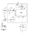
図1は、第1の実施の形態における充電システムの一構成例を示す全体図である。充電システムは、太陽電池110、電源コンセント210、充電器300、および、電池パック700を備える。電池パック700は、電池を筐体に収めたものであり、電池としてバッテリ710を備える。バッテリ710は、充電器300により充電された電気を蓄える2次電池である。充電器300は、バッテリ710を充電するものであり、昇圧コンバータ310、ダイオード320、交流アダプタ330、完了時刻設定部400、および、充電回路500を備える。
<1. First Embodiment>
[Configuration example of charging system]
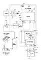
FIG. 1 is an overall view showing a configuration example of the charging system according to the first embodiment. The charging system includes a
太陽電池110は、太陽光エネルギーから自然エネルギー電力を生成するものである。太陽電池110は、生成した自然エネルギー電力を昇圧コンバータ310に供給する。電源コンセント210は、交流電力を交流アダプタ330に供給するものである。この交流電力は、自然エネルギー電力ではなく、石油の燃焼エネルギーなどから生成された商用電力である。
The
昇圧コンバータ310は、直流電力の電圧を一定の電圧に昇圧するものである。詳細には、昇圧コンバータ310は、太陽電池110から自然エネルギー電力を受電し、その電圧を一定の電圧に変換してダイオード320に出力する。変換される電圧は、バッテリ710のバッテリ電圧Vbよりも高い電圧に設定される。ダイオード320は、電流を一方向にのみ流す素子である。ダイオード320のアノードが昇圧コンバータ310に接続され、カソードが充電回路500に接続される。このため、充電回路500から昇圧コンバータ310への電流の逆流が防止される。太陽電池110からの直流電力は、ダイオード320を経由して信号線802を介して充電回路500に供給される。
交流アダプタ330は、電源コンセント210から出力された交流電力を直流電力に変換するものである。交流アダプタ330は、変換した直流電力を充電回路500に信号線803を介して供給する。
The
完了時刻設定部400は、バッテリ710の充電を完了すべき時刻(以下、「完了時刻Ts」と称する。)を設定するものである。完了時刻Tsの設定において、例えば、現在時刻Tcを基準として、充電を完了するまでの時間をユーザが入力する。完了時刻設定部400は、現在時刻Tcを取得し、入力された時間を現在時刻Tcに加算することにより完了時刻Tsを設定する。現在時刻Tcは、例えば、時、分、秒の単位まで取得される。設定された完了時刻Tsは、充電回路500に信号線801を介して出力される。
Completion
充電回路500は、充電器300を制御して、バッテリ710を充電させるものである。具体的には、充電回路500は、自然エネルギー電力のみをバッテリ710に供給することにより、完了時刻Tsまでにバッテリ710の充電が完了するか否かを判断する。完了すると判断した場合、充電回路500は、自然エネルギー電力のみによりバッテリ710を充電させる。完了しないと判断した場合、充電回路500は、自然エネルギー電力と、交流電源(すなわち、電源コンセント210)からの電力とによりバッテリ710を充電させる。
The charging
なお、太陽電池110は、特許請求の範囲に記載の自然エネルギー電源装置の一例である。完了時刻設定部400は、特許請求の範囲に記載の設定部の一例である。バッテリ710は、特許請求の範囲に記載の2次電池の一例である。
The
[充電回路の構成例]
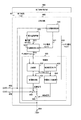
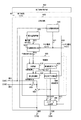
図2は、第1の実施の形態における充電回路500の一構成例を示すブロック図である。充電回路500は、出力電流測定部510、電力量取得部520、予測時刻算出部530、および、制御部600を備える。制御部600は、充電回路500の動作を制御するものであり、比較部610と、制御周期タイマ620と、給電制御部630と、充電完了判断部640と、スイッチ650および660とを備える。
[Configuration example of charging circuit]
FIG. 2 is a block diagram illustrating a configuration example of the charging
出力電流測定部510は、太陽電池110から信号線802を介して出力された出力電流Igの値を測定するものである。測定値の単位として、例えば、ミリアンペア(mA)が用いられる。出力電流測定部510は、測定した出力電流Igの値を予測時刻算出部530に信号線811を介して出力する。
The output
電力量取得部520は、バッテリ710の充電が完了するまでに供給すべき電力量Qを取得するものである。電力量Qの単位として、例えば、ミリワットアワー(mWh)が用いられる。電力量Qの取得方法については後述する。電力量取得部520は、取得した電力量Qを予測時刻算出部530に信号線813を介して出力する。また、電力量取得部520は、バッテリ710のバッテリ電圧Vbを測定し、その電圧値を充電完了判断部640に信号線812を介して出力する。バッテリ電圧Vbの単位として、例えば、ボルト(V)が用いられる。
The electric
予測時刻算出部530は、自然エネルギー電力のみによりバッテリ710の充電が完了する時刻(以下、「予測時刻Tg」と称する。)を算出するものである。予測時刻Tgは、例えば、秒単位で算出される。具体的には、予測時刻算出部530は、出力電流測定部510および電力量取得部520から出力電流Igおよび電力量Qの各値を受け取る。予測時刻算出部530は、電力量Qの単位をミリアンペアアワー(mAh)に換算した値を出力電流Igで除算した値に現在時刻Tcを加算し、加算後の時刻を予測時刻Tgとする。予測時刻算出部530は、算出した予測時刻Tgを比較部610に信号線814を介して出力する。
The predicted
スイッチ650は、給電制御部630の制御に従って、交流アダプタ330とバッテリ710との間の信号線を開閉するものである。スイッチ650が信号線を閉路することにより、交流アダプタ330からの電力がバッテリ710に供給され、スイッチ650が信号線を開路することにより交流アダプタ330からの電力供給が遮断される。スイッチ650の一方の端子は、交流アダプタ330に接続され、他方の端子は、スイッチ660に接続されている。
The
スイッチ660は、充電完了判断部640の制御に従って、電源(すなわち、太陽電池110および電源コンセント210)とバッテリ710との間の信号線を開閉するものである。スイッチ660が信号線を閉路することにより、電源からの電力がバッテリ710に供給され、スイッチ660が信号線を開路することによりバッテリ710への電力供給が遮断される。スイッチ660の一方の端子は、スイッチ650およびダイオード320に接続され、他方の端子はバッテリ710に接続されている。
The
比較部610は、完了時刻Tsと予測時刻Tgとを比較するものである。比較部610は、比較結果を給電制御部630に出力する。
The
制御周期タイマ620は、制御周期内の時刻を計時するものである。ここで、制御周期は、充電方式を切り替えるか否かの判断を行う周期である。例えば、制御周期は60秒に設定され、制御周期タイマ620は、秒単位で制御周期内の時刻を計時する。
The
給電制御部630は、制御周期ごとに充電方式を切り替えるか否かを判断し、判断結果に基づいて充電方式を切り替えるものである。具体的には、給電制御部630は、制御周期タイマ620のタイマ値Tcを参照し、タイマ値Tcが所定値(例えば、60秒)であれば、比較部610の比較結果を参照する。予測時刻Tgが完了時刻Tsより早いことを比較結果が示していた場合(すなわち、自然エネルギー電力のみにより、完了時刻Tsまでに充電が完了する場合)には、給電制御部630は、スイッチ650に信号線を開路させる。この結果、太陽電池110からの自然エネルギー電力のみがバッテリ710に供給される。一方、予測時刻Tgが完了時刻Ts以降であることを比較結果が示していた場合(すなわち、自然エネルギー電力のみでは完了時刻Tsまでに充電が完了しない場合)には、給電制御部630は、スイッチ650に信号線を閉路させる。この結果、太陽電池110および交流アダプタ330からの電力がバッテリ710に供給される。
The power
充電完了判断部640は、制御周期ごとにバッテリ710の充電が完了したか否かを判断するものである。具体的には、充電完了判断部640は、制御周期タイマ620のタイマ値Tcを参照し、タイマ値Tcが所定値(例えば、60秒)であれば、電力量取得部520が測定したバッテリ電圧Vbの値に基づいて充電が完了したか否かを判断する。例えば、バッテリ電圧Vbが所定の閾値Vth以上であれば、充電完了判断部640は、バッテリ710の充電が完了したと判断する。充電が完了したと判断した場合、充電完了判断部640は、スイッチ660に信号線を開路させて充電を終了させる。充電が完了していないと判断した場合、充電完了判断部640は、スイッチ660に信号線を閉路させて充電を継続させる。
The charging
なお、出力電流測定部510は、特許請求の範囲に記載の出力値取得部の一例である。
The output
図3は、第1の実施の形態における電力量取得部520の一構成例を示すブロック図である。電力量取得部520は、バッテリ電圧測定部521、電力量演算部522、および、充電率変換テーブル523を備える。
FIG. 3 is a block diagram illustrating a configuration example of the electric
バッテリ電圧測定部521は、バッテリ電圧Vbを測定するものである。バッテリ電圧測定部521は、測定した電圧値を電力量演算部522および充電完了判断部640に出力する。
The battery voltage measuring unit 521 measures the battery voltage Vb. Battery voltage measurement unit 521 outputs the measured voltage value to power
充電率変換テーブル523は、バッテリ電圧Vbと充電率Rとを対応付けて記憶するものである。この充電率Rは、バッテリ710の全容量に対する、残存容量の割合であり、単位は、例えば、パーセント(%)である。充電率変換テーブル523には、予め測定された、バッテリ電圧Vbおよび充電率Rが対応付けて格納されている。
The charging rate conversion table 523 stores the battery voltage Vb and the charging rate R in association with each other. The charging rate R is the ratio of the remaining capacity to the total capacity of the
電力量演算部522は、バッテリ電圧Vbから電力量Qを演算するものである。具体的には、まず、電力量演算部522は、バッテリ電圧Vbに対応する充電率Rを充電率変換テーブル523から読み出す。そして、電力量演算部522は、読み出した充電率Rを下記の式(1)に代入して電力量Qを演算する。
Q[mWh]=C[mWh](1−R[%]/100)・・・(1)
The power
Q [mWh] = C [mWh] (1-R [%] / 100) (1)
上記式(1)において、Cは、バッテリ710の全容量である。電力量演算部522は、演算した電力量Qを予測時刻算出部530に出力する。
In the above formula (1), C is the total capacity of the
図4は、第1の実施の形態における充電率変換テーブル523の一構成例を示す図である。例えば、満充電のバッテリ電圧Vbが4.2[V]であった場合、そのバッテリ電圧Vbに、充電率Rとして100[%]が対応付けて格納される。満充電の状態から全容量の2%分の容量を放電したときのバッテリ電圧Vbの測定値が4.1[V]であった場合、そのバッテリ電圧Vbに、充電率Rとして98[%]が対応付けて格納される。 FIG. 4 is a diagram illustrating a configuration example of the charging rate conversion table 523 according to the first embodiment. For example, when the fully charged battery voltage Vb is 4.2 [V], 100 [%] is stored in association with the battery voltage Vb as the charging rate R. When the measured value of the battery voltage Vb when discharging the capacity corresponding to 2% of the total capacity from the fully charged state is 4.1 [V], the battery voltage Vb is set to 98 [%] as the charging rate R. Are stored in association with each other.
[充電器の動作例]
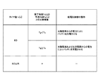
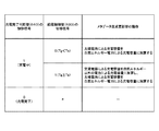
図5乃至7を参照して、充電器300の動作例について説明する。図5は、第1の実施の形態における給電制御部630の動作の一例を示す表である。タイマ値Tcが60秒であった場合、給電制御部630は、比較部610の比較結果を参照する。予測時刻Tgが完了時刻Tsより早い場合には、給電制御部630は、太陽電池110からの自然エネルギー電力によりバッテリ710を充電させる。一方、予測時刻Tgが完了時刻Ts以降である場合には、給電制御部630は、太陽電池110および交流電源(すなわち、電源コンセント210)からの電力のみによりバッテリ710を充電させる。
[Example of charger operation]
An example of the operation of the
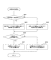
図6は、第1の実施の形態における充電器300の動作の一例を示すフローチャートである。この動作は、充電器300が太陽電池110および電源コンセント210に接続され、電池パック700が充電器300に装着されたときに開始する。充電器300は、現在時刻Tcから充電が完了するまでの時間の入力を受け付ける。充電器300内の完了時刻設定部400は、入力された時間を現在時刻に加算した時刻を完了時刻Tsとして充電回路500に設定する(ステップS910)。充電器300は、太陽電池110からの出力電流Igを測定し(ステップS920)、バッテリ電圧Vbに基づいて電力量Qを取得する(ステップS930)。そして、充電器300は、充電方式を切り替えるか否かを判断する給電制御処理を実行する(ステップS950)。
FIG. 6 is a flowchart illustrating an example of the operation of the
充電器300は、一定時間(例えば、60秒)が経過したか否かを判断する(ステップS970)。一定時間が経過していなければ(ステップS970:No)、充電器300は、ステップS970に戻る。一定時間が経過したのであれば(ステップS970:Yes)、充電器300は、充電が完了したか否かを判断する(ステップS980)。充電が完了していなければ(ステップS980:No)、充電器300は、ステップS910に戻る。充電が完了したのであれば(ステップS980:Yes)、充電器300は、充電を終了する。
The
図7は、第1の実施の形態における給電制御処理の一例を示すフローチャートである。予測時刻算出部530は、電力量Qおよび出力電流Igに基づいて予測時刻Tgを演算する(ステップS953)。制御部600は、予測時刻Tgが完了時刻Tsより早いか否かを判断する(ステップS956)。予測時刻Tgが完了時刻Tsより早い場合には(ステップS956:Yes)、給電制御部630は、太陽電池110からの自然エネルギー電力のみによりバッテリ710を充電させる(ステップS957)。予測時刻Tgが完了時刻Ts以降である場合には(ステップS956:No)、給電制御部630は、太陽電池110および交流電源からの電力によりバッテリ710を充電させる(ステップS958)。ステップS957またはS958の後、制御部600は、給電制御処理を終了する。
FIG. 7 is a flowchart illustrating an example of a power feeding control process according to the first embodiment. The predicted
このように、本技術の第1の実施の形態によれば、完了時刻Tsが設定されると、充電回路500は、出力電流Igおよび電力量Qに基づいて自然エネルギー電力のみによりバッテリ710の充電が完了する予測時刻Tgを算出する。そして、予測時刻Tgが完了時刻Tsより早い場合には、充電回路500は、自然エネルギー電力のみによりバッテリ710を充電させる。この構成によれば、完了時刻Tsまでに余裕がある場合において、自然エネルギー電力のみによりバッテリ710が充電されるため、自然エネルギー電力が有効に利用される。
As described above, according to the first embodiment of the present technology, when the completion time Ts is set, the charging
また、充電回路500は、予測時刻Tgが完了時刻Ts以降である場合には交流電源からの電力と自然エネルギー電力とにより充電させるため、完了時刻Tsまでに確実に充電を完了する。
Further, when the predicted time Tg is after the completion time Ts, the charging
なお、充電器300は、太陽電池110が生成した自然エネルギー電力により充電しているが、太陽電池110以外の電源装置が生成した自然エネルギー電力により充電を行ってもよい。例えば、充電器300は、風力発電装置や水力発電装置が生成した自然エネルギー電力を利用してもよい。
The
また、充電器300は、定電圧充電を行い、太陽電池110からの出力電流Igを測定しているが、定電流充電を行い、太陽電池110からの出力電圧を測定してもよい。この場合、予測時刻算出部530は、測定された出力電圧と電力量Qとから予測時刻Tgを算出する。
In addition, the
また、電力量取得部520は、充電率変換テーブル523から、バッテリ電圧Vbに対応する充電率Rを読み出しているが、バッテリ電圧Vbと充電率Rとの間の関係を示す関係式を定義しておき、この関係式に基づく演算により充電率Rを求めることもできる。
In addition, the electric
また、電力量取得部520は、充電率Rから電力量Qを演算しているが、予め演算しておいた電力量Qをバッテリ電圧Vbごとに記憶したテーブルを充電率変換テーブル523の代わりに備え、そのテーブルから電力量Qを読み出すこともできる。
The power
また、充電完了判断部640は、バッテリ電圧Vbと閾値とを比較することにより、充電が完了したか否かを判断しているが、バッテリ710の特性に基づいて、他の方式により充電が完了したか否かを判断することもできる。例えば、バッテリ710が、満充電に達するとバッテリ電圧がわずかに降下する特性をもつ場合、充電完了判断部640は、その電圧降下(−ΔV)を検出したときに充電を終了する−ΔV制御方式を使用することができる。あるいは、バッテリ710が満充電に近づくと発熱する特性をもつ場合、充電完了判断部640は、バッテリ710の温度を計測し、その温度が一定値に達したときに充電を終了する温度検出制御方式を使用することもできる。
In addition, the charging
<2.第2の実施の形態>
[充電回路の構成例]
次に、図8乃至10を参照して、本技術の第2の実施の形態について説明する。図8は、第2の実施の形態における充電回路501の一構成例を示す全体図である。充電回路501は、現在時刻Tcから完了時刻Tsまでの時間(以下、「残り時間Tr」と称する。)とバッテリ710の残存残量(以下、「バッテリ残量Cr」と称する。)とに基づいて充電制御を行う点において第1の充電回路500と異なる。充電回路501は、制御部600の代わりに制御部601を備える。制御部601は、給電制御部630の代わりに給電制御部631を備え、残り時間判断部670およびバッテリ残量判断部680をさらに備える点において第1の実施の形態の制御部600と異なる。本技術の第2の実施の形態における完了時刻設定部400は、比較部610のほか、残り時間判断部670にも完了時刻Tsを出力する。また、本技術の第2の実施の形態における電力量取得部520は充電完了判断部640のほか、バッテリ残量判断部680にも、バッテリ電圧Vbの測定値を出力する。
<2. Second Embodiment>
[Configuration example of charging circuit]
Next, a second embodiment of the present technology will be described with reference to FIGS. FIG. 8 is an overall view showing a configuration example of the charging
残り時間判断部670は、残り時間Trが所定の設定時間(例えば、12時間)以上であるか否かを判断するものである。残り時間判断部670は、判断結果を給電制御部631に出力する。
The remaining
バッテリ残量判断部680は、バッテリ残量Crが所定の設定容量(例えば、全容量のうちの10%分の容量)以上であるか否かを判断するものである。バッテリ残量Crの単位は、例えば、ミリワットアワー(mWh)である。バッテリ残量判断部680は、判断結果を給電制御部631に出力する。
The remaining battery
給電制御部631は、残り時間Trが設定時間以上であり、バッテリ残量Crが設定容量以上であり、かつ、予測時刻Tgが完了時刻Tsより早い場合に自然エネルギー電力のみにより充電させる。そうでない場合、給電制御部631は、自然エネルギー電力と交流電源からの電力とにより充電させる。
When the remaining time Tr is equal to or longer than the set time, the remaining battery level Cr is equal to or greater than the set capacity, and the predicted time Tg is earlier than the completion time Ts, the power
[充電器の動作例]
図9および図10を参照して、第2の実施の形態における充電器300の動作例について説明する。図9は、第2の実施の形態における給電制御部631の動作の一例を示す表である。残り時間Trが設定時間以上であり、バッテリ残量Crが設定容量以上であり、かつ、予測時刻Tgが完了時刻Tsより早い場合に、給電制御部631は太陽電池110からの電力のみによりバッテリ710を充電させる。残り時間Trが設定時間未満である場合、または、バッテリ残量Crが設定容量未満である場合、あるいは、予測時刻Tgが完了時刻Ts以降である場合に、給電制御部631は太陽電池110および交流電源からの電力によりバッテリ710を充電させる。
[Example of charger operation]
With reference to FIG. 9 and FIG. 10, the operation example of the
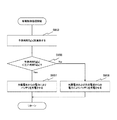
図10は、第2の実施の形態における給電制御処理の一例を示すフローチャートである。第2の実施の形態における給電制御処理は、ステップS954およびS955をさらに実行する点において第1の実施の形態の給電制御処理と異なる。 FIG. 10 is a flowchart illustrating an example of a power supply control process according to the second embodiment. The power supply control process in the second embodiment is different from the power supply control process in the first embodiment in that steps S954 and S955 are further executed.
予測時間Tgが演算されると(ステップS953)、給電制御部631は、残り時間Trが設定時間以上であるか否かを判断する(ステップS954)。残り時間Trが設定時間以上である場合(ステップS954:Yes)、給電制御部631は、バッテリ残量Crが設定容量以上であるか否かを判断する(ステップS955)。バッテリ残量Crが設定容量以上である場合(ステップS955:Yes)、給電制御部631は、予測時刻Tgが完了時刻Tsより早いか否かを判断する(ステップS956)。残り時間Trが設定時間未満である場合(ステップS954:No)、バッテリ残量Crが設定容量未満である場合(ステップS955:No)、または、予測時刻Tgが完了時刻Ts以降である場合(ステップS956:No)について説明する。この場合、給電制御部631は太陽電池110および交流電源からの電力によりバッテリ710を充電させる(ステップS958)。
When the predicted time Tg is calculated (step S953), the power
このように本技術の第2の実施の形態によれば、給電制御部631は、残り時間Trが設定時間未満である場合に、太陽電池110および交流電源からの電力によりバッテリ710を充電させる。これにより、完了時刻Tsまでに充電が間に合わなくなることが防止される。
As described above, according to the second embodiment of the present technology, when the remaining time Tr is less than the set time, the power
また、給電制御部631は、バッテリ残量Crが設定容量未満である場合に、太陽電池110および交流電源からの電力によりバッテリ710を充電させる。これにより、設定容量までに充電される時間が短くなり、ユーザの利便性が向上する。
In addition, when the battery remaining amount Cr is less than the set capacity, the power
<3.第3の実施の形態>
[充電回路の構成例]
次に、図11乃至14を参照して、本技術の第3の実施の形態について説明する。第3の実施の形態の充電器300は、天候予報データに基づいて予測時刻Tgを算出する点において第1の実施の形態と異なる。第3の実施形態の充電器300は、完了時刻設定部400および充電回路500の代わりに完了時刻設定部402および充電回路502を備える点において、第1の実施の形態の充電器300と異なる。
<3. Third Embodiment>
[Configuration example of charging circuit]
Next, a third embodiment of the present technology will be described with reference to FIGS. The
図11は、第3の実施の形態における充電回路502の一構成例を示す全体図である。充電回路502は、予測時刻算出部530の代わりに予測時刻算出部531を備え、関数取得部511および関数テーブル512をさらに備える点において第1の実施の形態の充電回路500と異なる。
FIG. 11 is an overall view showing a configuration example of the charging
完了時刻設定部402は、完了時刻Tsに加えて、天候予報データをさらに設定する。天候予報データは、予報期間と、その予報期間において予報された天候とを示す情報である。例えば、1月1日に天気が晴れることが予報された場合、予報期間として「1月1日」、天候として「晴れ」を示す天候予報データが設定される。完了時刻設定部402は、設定した天候予報データを関数取得部511に信号線805を介して出力する。
The completion
関数テーブル512は、天候ごとに、予測される出力電流Igの特性を示す関数を記憶するものである。太陽電池110の発電量は太陽光の光量に応じて増減するため、出力電流Igの値は、一般に、早朝から日中にかけて時間の経過に伴って上昇し、日中から夕方にかけて時間の経過に伴って減少する。この出力電流Igの特性に基づいて、予測される出力電流Igの値の時系列の変化を時間tの関数(例えば、2次関数)に近似することができる。また、太陽光の光量は天候に応じて変動する。このため、天候ごとに異なる関数が定義され、関数テーブル512に格納される。
The function table 512 stores a function indicating the characteristics of the predicted output current Ig for each weather. Since the amount of power generated by the
関数取得部511は、天候に対応する関数Ig(t)を取得するものである。具体的には、関数取得部511は、天候予報データを受け取ると、その天候予報データの示す天候に対応する関数Ig(t)を関数テーブル512から信号線915を介して読み出す。関数取得部511は、読み出した関数Ig(t)と天候予報データの示す予報期間とを予測時刻算出部531に信号線916を介して出力する。
The
予測時刻算出部531は、関数Ig(t)および予報期間を受けとった場合に、その関数Ig(t)から、予測時刻Tgを算出する。具体的には、予測時刻算出部531は、現在時刻Tcから予報期間が経過するまでの期間におけるIg(t)の積分値を電力量に換算した値が電力量Qと等しくなる時間tを算出する。予報期間内の積分値に対応する電力量が、電力量Qに満たなければ、予測時刻算出部531は、予報期間が経過するまでの関数Ig(t)の積分値と予報期間経過後の出力電流Igの積分値との加算値に対応する電力量が電力量Qと等しくなる時間tを算出する。予測時刻算出部531は、算出した時間tを現在時刻Tcに加算した値を予測時刻Tgとする。一方、関数Ig(t)を受け取らなかった場合、予測時刻算出部531は、測定された出力電流Igから予測時刻Tgを算出する。
When the predicted
なお、関数取得部511は、特許請求の範囲に記載の予測値取得部の一例である。関数テーブル512は、特許請求の範囲に記載の予測値記憶部の一例である。
The
図12は、第3の実施の形態における出力電流の特性を示す関数の一例を示すグラフである。図12において、点線で示す関数は、理想的な環境における、出力電流Igの予測値の変化を示す関数である。実線で示す関数は、実際に測定された出力電流Igの変化を近似した関数である。太陽電池110の発電量は、地域や設置環境により異なるため、実測値は、理想値と異なることが多い。実測値が得られていない場合は理想値に基づく関数が関数テーブル512に格納され、実測値が得られた場合は、点線で示す関数を実測値に基づいて補正した関数が関数テーブル512に格納される。図12(a)は、晴れの日における出力電流Igの特性を示す関数の一例であり、図12(b)は、曇りの日における出力電流Igの特性を示す関数の一例である。図12(c)は、雨の日における出力電流Igの特性を示す関数の一例である。
FIG. 12 is a graph illustrating an example of a function indicating the characteristics of the output current in the third embodiment. In FIG. 12, a function indicated by a dotted line is a function indicating a change in the predicted value of the output current Ig in an ideal environment. The function indicated by the solid line is a function that approximates the change in the actually measured output current Ig. Since the amount of power generated by the
[充電器の動作例]
図13および図14を参照して、第3の実施の形態における充電器300の動作例について説明する。図13は、第3の実施の形態における充電器300の動作の一例を示す表である。第3の実施の形態の充電器300の動作は、ステップS940をさらに実施する点において第1の実施の形態の充電器300の動作と異なる。充電器300は、電力量Qを取得し(ステップS930)、天候予報データの入力を受け付ける。天候予報データが入力されると、完了時刻設定部402は、その天候予報データを充電回路502に設定する(ステップS940)。そして、充電器300は、給電制御処理を実行する(ステップS950)。
[Example of charger operation]
With reference to FIG. 13 and FIG. 14, the operation example of the
図14は、第3の実施の形態における給電制御処理の一例を示すフローチャートである。第3の実施の形態の給電制御処理は、ステップS951およびS952をさらに実行する点において第1の実施の形態の給電制御処理と異なる。 FIG. 14 is a flowchart illustrating an example of a power supply control process according to the third embodiment. The power supply control process of the third embodiment is different from the power supply control process of the first embodiment in that steps S951 and S952 are further executed.
充電回路502は、天候予報データを取得したか否かを判断する(ステップS951)。天候予報データを取得しているのであれば(ステップS951:Yes)、予測時刻算出部531は、その天候予報データの示す天候に対応する関数Ig(t)に基づいて予測時刻Tgを演算する(ステップS952)。天候予報データを取得していなければ(ステップS951:No)、予測時刻算出部531は、測定した出力電流Igに基づいて予測時刻Tgを演算する(ステップS953)。ステップS952またはS953の後、制御部600は、予測時刻Tgが完了時刻Tsより早いか否かを判断する(ステップS956)。
The charging
このように、本技術の第3の実施の形態によれば、充電回路502は、天候予報データが設定されると、その天候予報データの示す天候に対応する予測値を関数テーブル512から読み出して、その予測値および電力量Qに基づいて予測時刻Tgを算出する。これにより、充電回路502は、天候に伴う自然エネルギー電力の変動に基づいて、予測時刻Tgを、より正確に算出することができる。
As described above, according to the third embodiment of the present technology, when the weather forecast data is set, the charging
なお、天候予報データは、ユーザが入力する構成としているが、充電器300が、無線または有線の通信を行うことにより、天候予報データを取得する構成とすることもできる。
Although the weather forecast data is configured to be input by the user, the
また、充電回路502は、天候ごとに出力電流Igの関数を記憶しておく構成としているが、関数でない予測値を天候ごとに記憶しておく構成とすることもできる。例えば、充電回路502は、出力電流Igの平均値や中央値を天候ごとに記憶しておくこともできる。
The charging
また、充電回路502は、関数取得部511および関数テーブル512と出力電流測定部510とを両方備える構成としている。しかし、充電回路502は、関数取得部511および関数テーブル512と出力電流測定部510とのうちのいずれか一方のみを備える構成とすることもできる。
The charging
<4.第4の実施の形態>
[充電システムの構成例]
次に、図15乃至21を参照して、本技術の第4の実施の形態について説明する。第4の実施の形態の充電システムは、自然エネルギー電力による充電容量と、自然エネルギー電力以外の電力による充電容量とを記憶する点において第1の実施形態の充電システムと異なる。
<4. Fourth Embodiment>
[Configuration example of charging system]
Next, a fourth embodiment of the present technology will be described with reference to FIGS. The charging system according to the fourth embodiment is different from the charging system according to the first embodiment in that a charging capacity based on natural energy power and a charging capacity based on power other than natural energy power are stored.
図15は、第4の実施の形態における充電システムの一構成例を示す全体図である。第4の実施の形態の充電システムは、充電器300および電池パック700の代わりに充電器303および電池パック703を備える点において第1の実施の形態の充電システムと異なる。充電器303は、充電回路500の代わりに充電回路503を備える点において第1の実施形態の充電回路500と異なる。電池パック703は、メモリ720をさらに備える点において第1の実施の形態の電池パック700と異なる。
FIG. 15 is an overall view showing a configuration example of the charging system according to the fourth embodiment. The charging system of the fourth embodiment differs from the charging system of the first embodiment in that a
充電回路503は、自然エネルギー電力による充電容量と、自然エネルギー電力以外の電力による充電容量とを示す情報をメタデータとして生成する。充電回路503は、信号線806を介してメタデータをメモリ720に出力する。メモリ720は、メタデータを記憶するものである。
The charging
メモリ720に記憶されたメタデータは、電池パック703を電源とする電子機器750により読み出される。電子機器750は、電池パック703が装着されると、メモリ720からメタデータを読み出し、そのメタデータに基づいて自然エネルギー電力による充電容量と、自然エネルギー電力以外の電力による充電容量とを表示する。
The metadata stored in the
なお、メタデータは、特許請求の範囲に記載の充電データの一例である。メモリ720は、特許請求の範囲に記載の充電データ記憶部の一例である。電子機器750は、特許請求の範囲に記載の表示部の一例である。
Note that the metadata is an example of the charging data described in the claims. The
[充電回路の構成例]
図16は、第4の実施の形態における充電回路503の一構成例を示すブロック図である。充電回路503は、メタデータ生成部540をさらに備える点において第1の実施の形態の充電回路500と異なる。
[Configuration example of charging circuit]
FIG. 16 is a block diagram illustrating a configuration example of the charging
メタデータ生成部540は、メタデータを生成して出力するものである。詳細には、メタデータ生成部540は、給電制御部630から信号線831を介してスイッチ650を制御するための切替信号を取得する。この切替信号には、例えば、スイッチ650に信号線を閉路させる場合に「1」の値が設定され、開路させる場合に「0」の値が設定される。また、メタデータ生成部540は、充電完了判断部640から信号線832を介してスイッチ660を制御するための制御信号を取得する。この制御信号には、例えば、スイッチ660に信号線を閉路させる場合に「1」の値が設定され、開路させる場合に「0」の値が設定される。さらに、メタデータ生成部540は、出力電流測定部510から出力電流Igの測定値を取得し、信号線833を介して、タイマ値Tcを取得する。そして、メタデータ生成部540は、太陽電池110からの電力により充電中の場合に出力電流Igの測定値にタイマ値Tcを積算した値を自然エネルギー電力による充電容量に加算する。また、交流電源からの電力により充電中の場合に、メタデータ生成部540は、交流アダプタ330の出力電流にタイマ値Tcを積算した値を、自然エネルギー電力以外の電力による充電容量に加算する。メタデータ生成部540は、各充電容量を示すメタデータを生成してメモリ720に出力する。
The
なお、メタデータ生成部540は、特許請求の範囲に記載の充電データ生成部の一例である。
The
図17は、第4の実施の形態におけるメタデータ生成部540の一構成例を示すブロック図である。メタデータ生成部540は、積算部541およびメタデータ生成更新部542を備える。
FIG. 17 is a block diagram illustrating a configuration example of the
積算部541は、制御周期内の出力電流Igの積算値を電力量に換算した値である充電量Cgを演算するものである。充電量Cgの単位は、例えば、ミリワットアワー(mWh)である。積算部541は、充電量Cgをメタデータ生成更新部542に出力する。
The
メタデータ生成更新部542は、メタデータを生成するとともに更新するものである。スイッチ660が信号線を閉路しており、かつ、スイッチ650が信号線を開路している場合(すなわち、太陽電池110からの電力のみにより充電中の場合)について説明する。この場合、メタデータ生成更新部542は、充電量Cgを自然エネルギー電力による充電容量に加算する。一方、スイッチ660および650が、いずれも信号線を閉路している場合(すなわち、太陽電池110および交流電源からの電力により充電中の場合)について説明する。この場合、メタデータ生成更新部542は、充電量Cgを自然エネルギー電力による充電容量に加算し、交流アダプタ330の出力電流を制御周期内で積算した値を、自然エネルギー電力以外の電力による充電容量に加算する。メタデータ生成更新部542は、これらの充電容量を示す情報をメタデータとして生成して出力する。メタデータ生成更新部542は、メタデータを生成した後、タイマ値Tcの増加に伴い、メモリ720内のメタデータにおいて各充電容量を更新する。スイッチ660が信号線を開路した場合(すなわち、充電が完了した場合)、メタデータ生成更新部542は、メタデータの更新を終了する。
The metadata generation / updating
[充電器の動作例]
図18および図19を参照して、第4の実施の形態における充電器303の動作例について説明する。図18は、第4の実施の形態におけるメタデータ生成更新部542の動作の一例を示す表である。充電完了判断部640の制御信号の値が「1」であり、給電制御部630の切替信号の値が「0」である場合について説明する。この場合においては、予測時間Tgが完了時間Tsより早いため、太陽電池110からの電力のみによりバッテリ710が充電されている。このため、メタデータ生成更新部542は、太陽電池110による充電容量(すなわち、充電量Cg)を自然エネルギー電力による充電容量に加算する。一方、切替信号および制御信号の値がいずれも「1」である場合について説明する。この場合においては、予測時間Tgが完了時間Ts以降であるため、太陽電池110および交流電源からの電力によりバッテリ710が充電されている。このため、メタデータ生成更新部542は、太陽電池110による充電容量を自然エネルギー電力による充電容量に加算し、交流電源による充電容量を、自然エネルギー電力以外の電力による充電容量に加算する。充電完了判断部640の制御信号の値が「0」である場合(すなわち、充電が完了した場合)、メタデータ生成更新部542は、メタデータの更新を終了する。
[Example of charger operation]
With reference to FIG. 18 and FIG. 19, the operation example of the
図19は、第4の実施の形態における充電器303の動作の一例を示すフローチャートである。充電器303の動作は、ステップS960をさらに実行する点において第1の実施の形態の充電器300の動作と異なる。
FIG. 19 is a flowchart illustrating an example of the operation of the
充電器303は、給電制御処理を実行し(ステップS950)、メタデータを生成するとともに更新する(ステップS960)。そして、充電器303は、一定時間が経過したか否かを判断する(ステップS970)。
The
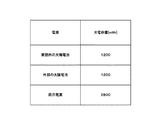
図20は、第4の実施の形態におけるメタデータの一構成例を示す図である。メタデータは、自然エネルギー電力による充電容量を格納するための領域551と、自然エネルギー電力以外の電力による充電容量を格納するための領域552とを備える。例えば、自然エネルギー電力により4800[mWh]の容量が充電され、自然エネルギー電力以外の電力により2800[mWh]の容量が充電された場合、領域551に「4800」を示すデータが格納され、領域552に「2800」を示すデータが格納される。
FIG. 20 is a diagram illustrating a configuration example of metadata according to the fourth embodiment. The metadata includes a
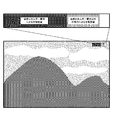
図21は、第4の実施の形態におけるメタデータの示す内容の表示例である。電子機器750は、自然エネルギー電力による充電容量と自然エネルギー電力以外の電力による充電容量とをユーザが識別しやすいように表示する。例えば、電子機器750は、バッテリの全容量を一本のバーで表示し、そのバーにおいて自然エネルギー電力による充電率にバー全体の長さを乗算した長さの部分を黒で表示する。また、電子機器750は、そのバーにおいて自然エネルギー電力でない電力による充電率にバー全体の長さを乗算した長さの部分を灰色で表示し、残りの部分を白で表示する。
FIG. 21 is a display example of the contents indicated by the metadata in the fourth embodiment. The
このように、本技術の第4の実施の形態によれば、充電回路503は、自然エネルギー電力による充電容量と自然エネルギー電力以外の電力による充電容量とを示すメタデータを出力する。これにより、電子機器750は、各充電容量を表示することができる。電源ごとの充電容量の表示により、ユーザは、充電において、自然エネルギー電力がどの程度利用されたかを容易に把握することができる。
As described above, according to the fourth embodiment of the present technology, the charging
また、電池パック703内のメモリ720にメタデータが記憶される。このため、充電器303の外部の機器であっても、電池パック703を装着可能であれば、各充電容量を取得することができる。
Further, metadata is stored in the
なお、電子機器750がメタデータの示す内容を表示する構成としているが、メタデータの示す内容を表示する表示部を充電器303がさらに備える構成とすることもできる。
Note that although the
<5.第5の実施の形態>
[充電システムの構成例]
次に、図22乃至26を参照して、本技術の第5の実施の形態について説明する。第5の実施の形態の充電システムは、交流電力の供給源を取得してメタデータを生成する点において第4の実施形態の充電システムと異なる。
<5. Fifth embodiment>
[Configuration example of charging system]
Next, a fifth embodiment of the present technology will be described with reference to FIGS. The charging system of the fifth embodiment differs from the charging system of the fourth embodiment in that metadata is generated by acquiring a supply source of AC power.
図22は、第5の実施の形態における充電システムの一構成例を示す全体図である。第5の実施の形態における充電システムは、変換切替部220をさらに備え、充電器303の代わりに充電器304を備える点において第4の実施の形態の充電システムと異なる。
FIG. 22 is an overall view illustrating a configuration example of the charging system according to the fifth embodiment. The charging system according to the fifth embodiment is different from the charging system according to the fourth embodiment in that it further includes a
変換切替部220は、商用電源および自然エネルギー電源から商用電力および自然エネルギー電力を受電し、いずれかを電源コンセント210に供給するものである。この自然エネルギー電源は、例えば、太陽電池110と設置場所が異なる外部の太陽光発電装置である。また、変換切替部220は、PLC(Power Line Communications)モジュールなどを使用して、供給する交流電力の交流波形に電源識別子IDを重畳する。電源識別子IDは、交流電力の供給源を識別するための識別子である。電源識別子IDには、例えば、交流電力が商用電源から供給されている場合に「0」の値が設定され、自然エネルギー電源から供給されている場合に「1」の値が設定される。
The
充電器304は、交流アダプタ330および充電回路503の代わりに交流アダプタ340および充電回路504を備える点において第4の実施の形態の充電器303と異なる。
The
交流アダプタ340は、受電した交流電力の交流波形から電源識別子IDを分離する。交流アダプタ340は、その交流電力を直流電力に変換して信号線803を介して充電回路504に供給するとともに、電源識別子IDを充電回路504に信号線807を介して出力する。
The
充電回路504は、交流電力により充電する場合、メタデータにおいて、電源識別子IDの示す供給源に対応する充電容量の値を更新する。
When charging with AC power, the charging
なお、交流アダプタ340は、特許請求の範囲に記載の分離部の一例である。電源識別子IDは、特許請求の範囲に記載の電源識別信号の一例である。
The
図23は、第5の実施の形態における変換切替部220の一構成例を示すブロック図である。変換切替部220は、インバータ221と、切替制御部222と、電源識別子重畳部223および224と、電源識別子記憶部225とスイッチ226とを備える。
FIG. 23 is a block diagram illustrating a configuration example of the
インバータ221は、自然エネルギー電源から供給された直流電力を交流電力に変換するものである。インバータ221は、変換後の交流電力を電源識別子重畳部223へ出力する。
The
切替制御部222は、交流電力の供給源を切り替える制御を行うものである。具体的には、切替制御部222は、自然エネルギー電力の発電量を監視し、その発電量に基づいてスイッチ226を制御する。例えば、切替制御部222は、自然エネルギー電力の発電量が閾値以上である場合に、交流電力の供給源を自然エネルギー電源に切り替え、閾値未満である場合に供給源を商用電源に切り替える。
The switching
電源識別子重畳部223は、電源識別子記憶部225から自然エネルギー電源に対応する電源識別子IDを取得し、インバータ221から供給された交流電力の交流波形において、その電源識別子IDを重畳するものである。電源識別子IDが交流波形に重畳された交流電力は、スイッチ226の入力端子に出力される。
The power
電源識別子重畳部224は、電源識別子記憶部225から商用電源に対応する電源識別子IDを取得し、商用電源から供給された交流電力の交流波形において、その電源識別子IDを重畳するものである。電源識別子IDが交流波形に重畳された交流電力は、スイッチ226の入力端子に出力される。
The power
電源識別子記憶部225は、電源ごとに電源識別子IDを記憶するものである。スイッチ226は、切替制御部222の制御に従って交流電力の供給源を切り替えるものである。スイッチ226は、2つの入力端子と1つの出力端子を備える。一方の入力端子は電源識別子重畳部223に接続され、他方の入力端子は電源識別子重畳部224に接続されている。出力端子は、変圧器などを経由して電源コンセント210に接続されている。
The power source
図24は、第5の実施の形態におけるメタデータ生成部545の一構成例を示すブロック図である。第5の実施の形態のメタデータ生成部545は、メタデータ生成更新部542の代わりにメタデータ生成更新部543を備える点において第4の実施の形態のメタデータ生成部540と異なる。
FIG. 24 is a block diagram illustrating a configuration example of the
メタデータ生成更新部543は、給電制御部630および充電完了判断部640からの切替信号および制御信号に加えて、交流アダプタ340から電源識別子IDを受け取る。メタデータ生成更新部543は、太陽電池110および交流電源からの電力によりバッテリ710が充電されている場合において、電源識別子IDを参照して交流電力の供給源を識別する。外部の太陽電池が交流電力の供給源である場合、メタデータ生成更新部543は、交流電源および家庭内の太陽電池110からの電力による充電容量を自然エネルギー電力による充電容量に加算する。商用電源が交流電力の供給源である場合、メタデータ生成更新部543は、太陽電池110による充電容量を自然エネルギー電力による充電容量に加算し、交流電源による充電容量を自然エネルギー電力以外の電力による充電容量に加算する。
The metadata generation / updating
[充電器の動作例]
図25を参照して、第5の実施の形態における充電器304の動作例について説明する。図25は、第5の実施の形態におけるメタデータ生成更新部543の動作の一例を示す表である。充電完了判断部640の制御信号の値と、給電制御部630の切替信号の値とがいずれも「1」であり、かつ、電源識別子IDが「0」である場合について説明する。この場合、太陽電池110および商用電源からの電力がバッテリ710に供給されている。このため、メタデータ生成更新部543は、太陽電池110による充電容量を自然エネルギー電力による充電容量に加算し、交流電源による充電容量を自然エネルギー電力以外の電力による充電容量に加算する。
[Example of charger operation]
With reference to FIG. 25, an operation example of the
一方、切替信号および制御信号の各値がいずれも「1」であり、かつ、電源識別子IDが「1」である場合について説明する。この場合、家庭内の太陽電池110からの電力と、外部の太陽電池からの電力とがバッテリ710に供給されている。このため、メタデータ生成更新部543は、家庭内の太陽電池110および交流電源による充電容量を、自然エネルギー電力による充電容量に加算する。
On the other hand, the case where each value of the switching signal and the control signal is “1” and the power supply identifier ID is “1” will be described. In this case, power from the
このように、本技術の第5の実施の形態によれば、充電回路504は、電源識別子IDを取得し、その電源識別子IDに基づいてメタデータを生成する。これにより、交流電力の供給源が複数であっても、供給源ごとに充電容量を算出することができる。
Thus, according to the fifth embodiment of the present technology, the charging
なお、変換切替部220は、供給源が自然エネルギー電源であるか否かを識別するための電源識別子IDを重畳しているが、自然エネルギー電源の種類を識別するための識別子を重畳してもよい。例えば、変換切替部220は、水力発電装置、太陽光発電装置、または、地熱発電装置などの各電源を識別するための電源識別子を重畳してもよい。
The
また、充電器304は、自然エネルギー電力による充電容量と、自然エネルギー電力でない電力による充電容量とを算出しているが、自然エネルギー電力の供給源ごとに充電容量を算出してもよい。例えば、充電器304は、家庭内の太陽電池110による充電容量と、外部の太陽電池による充電容量と、商用電源による充電容量とをそれぞれ算出する。そして、充電器304は、図26に示すように各充電容量を示すメタデータを生成する。このメタデータには、電源を示す情報を格納するための複数の領域と、充電容量を示す情報を格納するための領域とが対応付けて設けられる。
In addition, the
また、変換切替部220は、電源識別子IDを商用電源からの交流電力と、自然エネルギー電源からの交流電力との両方に重畳しているが、いずれか一方のみに重畳してもよい。
In addition, the
<6.第6の実施の形態>
[充電システムの構成例]
次に、図27および図28を参照して、本技術の第6の実施の形態について説明する。第6の実施の形態における充電システムは、電子機器を経由して充電を行う点において第5の実施の形態の充電システムと異なる。
<6. Sixth Embodiment>
[Configuration example of charging system]
Next, with reference to FIGS. 27 and 28, a sixth embodiment of the present technology will be described. The charging system according to the sixth embodiment is different from the charging system according to the fifth embodiment in that charging is performed via an electronic device.
図27は、第6の実施の形態における充電システムの一構成例を示す全体図である。第6の実施の形態における充電システムは、電子機器751をさらに備える点において第5の実施の形態における充電システムと異なる。
FIG. 27 is an overall view showing a configuration example of the charging system according to the sixth embodiment. The charging system in the sixth embodiment is different from the charging system in the fifth embodiment in that it further includes an
電子機器751は、電池パック703を電源とする機器であり、電子機器制御部760および表示部770を備える。電子機器制御部760は、電子機器751全体を制御するものである。電子機器制御部760は、充電器304から信号線804を介して直流電力を受電し、信号線806を介してメタデータを受け取る。電子機器制御部760は、受電した直流電力をバッテリ710に信号線808を介して出力し、メタデータをメモリ720に信号線809を介して出力する。また、電子機器制御部760は、メモリ720からメタデータを読み出して、そのメタデータの示す内容を表示部770に表示させる。表示部770は、メタデータの示す内容を表示するものである。
The
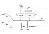
図28は、第6の実施の形態における電子機器制御部760の一構成例を示すブロック図である。電子機器制御部760は、プロセッサ761、メモリ762、および、バス763を備える。
FIG. 28 is a block diagram illustrating a configuration example of the electronic
プロセッサ761は、電子機器751全体を制御するものである。プロセッサ761は、充電器304から受け取ったメタデータを電池パック703へ出力する。また、プロセッサ761は、電池パック703に記憶されたメタデータを読み出して、そのメタデータの示す内容を表示するためのデータを生成し、表示部770へ信号線881を介して出力する。
The
メモリ762は、プロセッサ761が直接アクセス可能な主記憶装置である。バス763は、プロセッサ761やメモリ762がデータを送受信するための共通の経路である。
The
このように、本技術の第6の実施の形態によれば、充電器304は、電子機器751を経由して電池パック703を充電する。これにより、充電器304は、電子機器751に電池パック703を装着したままの状態で電池パック703を充電することができ、ユーザの利便性が向上する。
As described above, according to the sixth embodiment of the present technology, the
なお、メモリ720を電池パック703内に設ける構成としているが、メモリ720を電池パック703内でなく、電子機器751内に設ける構成とすることもできる。これにより、電池パック703にメモリ720を設ける必要がなくなる。
Note that although the
<7.変形例>
[充電回路の構成例]
次に、図29を参照して、本技術の変形例について説明する。図29は、変形例の充電回路506の一構成例を示すブロック図である。充電回路506は、制御部600の代わりに制御部606を備える点において、第1の実施の形態の充電回路500と異なる。制御部606は、スイッチ650の代わりにスイッチ651を備える点において第1の実施の形態の制御部600と異なる。
<7. Modification>
[Configuration example of charging circuit]
Next, a modified example of the present technology will be described with reference to FIG. FIG. 29 is a block diagram illustrating a configuration example of a
スイッチ651は、2つの入力端子と1つの出力端子とを備える。スイッチ651の一方の入力端子は、ダイオード320に接続され、他方の入力端子は、交流アダプタ330に接続される。スイッチ651の出力端子は、スイッチ660に接続される。給電制御部630は、予測時刻Tgが完了時刻Tsより早い場合にはスイッチ651の入力先をダイオード320に切り替え、予測時刻Tgが完了時刻Ts以降の場合にはスイッチ651の入力先を交流アダプタ330に切り替える。これにより、予測時刻Tgが完了時刻Ts以降である場合に交流電力のみによりバッテリ710が充電される。この構成によれば、自然エネルギー電力と交流電源からの電力とのうちのいずれか一方しか供給されないため、両方を供給する第1の実施形態の充電器システムと比較して過充電が生じる可能性が低くなる。
The
なお、上述の実施の形態は本技術を具現化するための一例を示したものであり、実施の形態における事項と、特許請求の範囲における発明特定事項とはそれぞれ対応関係を有する。同様に、特許請求の範囲における発明特定事項と、これと同一名称を付した本技術の実施の形態における事項とはそれぞれ対応関係を有する。ただし、本技術は実施の形態に限定されるものではなく、その要旨を逸脱しない範囲において実施の形態に種々の変形を施すことにより具現化することができる。 The above-described embodiment shows an example for embodying the present technology, and the matters in the embodiment and the invention-specific matters in the claims have a corresponding relationship. Similarly, the invention specific matter in the claims and the matter in the embodiment of the present technology having the same name as this have a corresponding relationship. However, the present technology is not limited to the embodiment, and can be embodied by making various modifications to the embodiment without departing from the gist thereof.
また、上述の実施の形態において説明した処理手順は、これら一連の手順を有する方法として捉えてもよく、また、これら一連の手順をコンピュータに実行させるためのプログラム乃至そのプログラムを記憶する記録媒体として捉えてもよい。この記録媒体として、例えば、CD(Compact Disc)、MD(MiniDisc)、DVD(Digital Versatile Disk)、メモリカード、ブルーレイディスク(Blu-ray Disc(登録商標))等を用いることができる。 Further, the processing procedure described in the above embodiment may be regarded as a method having a series of these procedures, and a program for causing a computer to execute these series of procedures or a recording medium storing the program. You may catch it. As this recording medium, for example, a CD (Compact Disc), an MD (MiniDisc), a DVD (Digital Versatile Disk), a memory card, a Blu-ray Disc (registered trademark), or the like can be used.
なお、本技術は以下のような構成もとることができる。
(1)2次電池の充電を完了すべき時刻である完了時刻を設定する設定部と、
自然エネルギーから自然エネルギー電力を生成する電源装置である自然エネルギー電源装置からの電圧または電流の出力値を取得する出力値取得部と、
前記2次電池の充電が完了するまでに供給すべき電力量を取得する電力量取得部と、前記出力値と前記電力量とに基づいて前記自然エネルギー電力のみにより前記2次電池の充電が完了する時刻を予測時刻として算出する予測時刻算出部と、
前記予測時刻が前記完了時刻より早い場合には前記自然エネルギー電力のみにより前記2次電池を充電させる制御部と
を具備する充電器。
(2)前記制御部は、前記予測時刻が前記完了時刻以降である場合には前記自然エネルギー電源装置以外の電源装置が生成した電力により前記2次電池を充電させる
前記(1)に記載の充電器。
(3)前記制御部は、前記予測時刻が前記完了時刻以降である場合には前記自然エネルギー電力をさらに供給して前記2次電池を充電させる
前記(2)に記載の充電器。
(4)前記設定部は、天候を示す天候予報データをさらに設定し、
前記出力値取得部は、前記設定された天候予報データに基づいて前記出力値を天候ごとに予測し、
前記予測時刻算出部は、前記予測された天候ごとの前記出力値および前記電力量に基づいて前記予測時刻を算出する
前記(3)記載の充電器。
(5)前記自然エネルギー電力による前記2次電池の充電容量と前記自然エネルギー電力以外の電力による前記2次電池の充電容量とを示す情報を充電データとして生成して出力する充電データ生成部をさらに具備する前記(2)から(4)のいずれかに記載の充電器。
(6)前記自然エネルギー電源装置以外の電源装置は、電力の供給源を識別するための電源識別信号が交流波形に重畳された交流電力を受電し、前記交流波形から前記電源識別信号を分離する分離部をさらに具備し、
前記充電データ生成部は、前記分離された電源識別信号に基づいて前記充電データを生成する
前記(5)に記載の充電器。
(7)前記制御部は、現在時刻から前記完了時刻までの時間である残り時間が所定の時間以上である場合には前記自然エネルギー電力のみにより前記2次電池を充電させる
前記(1)から(6)のいずれか記載の充電器。
(8)前記制御部は、前記2次電池の残存容量が所定の容量以上である場合には前記自然エネルギー電力のみにより前記2次電池を充電させる
前記(1)から(7)のいずれかに記載の充電器。
(9)前記設定部は、天候を示す天候予報データをさらに設定し、
前記出力値取得部は、前記設定された天候予報データに基づいて前記出力値を天候ごとに予測し、
前記予測時刻算出部は、前記予測された天候ごとの前記出力値および前記電力量に基づいて前記予測時刻を算出する
前記(1)から(8)のいずれかに記載の充電器。
(10)2次電池の充電を完了すべき時刻である完了時刻を設定する設定部と、自然エネルギーから自然エネルギー電力を生成する電源装置である自然エネルギー電源装置からの電圧または電流の出力値を取得する出力値取得部と、前記2次電池の充電が完了するまでに供給すべき電力量を取得する電力量取得部と、前記出力値と前記電力量とに基づいて前記自然エネルギー電力のみにより前記2次電池の充電が完了する時刻を予測時刻として算出する予測時刻算出部と、前記予測時刻が前記完了時刻より早い場合には前記自然エネルギー電力のみにより前記2次電池を充電させ、前記予測時刻が前記完了時刻以降である場合には前記自然エネルギー電源装置以外の電源装置が生成した電力により前記2次電池を充電させる制御部と、前記自然エネルギー電力による前記2次電池の充電容量と前記自然エネルギー電力以外の電力による前記2次電池の充電容量とを示す情報を充電データとして生成して出力する充電データ生成部とを備える充電器と、
前記出力された充電データを記憶する充電データ記憶部と、前記2次電池とを備える電池パックとを
具備する充電システム。
(11)前記自然エネルギー電源装置以外の電源装置は、電力の供給源を識別するための電源識別信号が交流波形に重畳された交流電力を受電し、
前記充電器は、前記交流波形から前記電源識別信号を分離する分離部をさらに備え、前記充電データ生成部は、前記分離された電源識別信号に基づいて前記充電データを生成する
前記(10)に記載の充電システム。
(12)前記充電データに基づいて前記自然エネルギー電力による前記2次電池の充電容量と前記自然エネルギー電力以外の電力による前記2次電池の充電容量とを表示する表示部をさらに具備する前記(10)または(11)に記載の充電システム。
(13)2次電池の充電を完了すべき時刻である完了時刻を設定する設定手順と、
自然エネルギーから自然エネルギー電力を生成する電源装置である自然エネルギー電源装置からの電圧または電流の出力値を取得する出力値取得手順と、
前記2次電池の充電が完了するまでに供給すべき電力量を取得する電力量取得手順と、前記出力値と前記電力量とに基づいて前記自然エネルギー電力のみにより前記2次電池の充電が完了する時刻を予測時刻として算出する予測時刻算出手順と、
前記予測時刻が前記完了時刻より早い場合には前記自然エネルギー電力のみにより前記2次電池を充電させる制御手順と
を具備する充電方法。
In addition, this technique can also take the following structures.
(1) a setting unit that sets a completion time that is a time at which charging of the secondary battery should be completed;
An output value acquisition unit that acquires an output value of voltage or current from a natural energy power supply device that is a power supply device that generates natural energy power from natural energy;
Charging of the secondary battery is completed only by the natural energy power based on the output value and the electric energy based on the output value and the electric energy, and an electric energy acquisition unit that acquires the electric energy to be supplied until the charging of the secondary battery is completed A predicted time calculation unit that calculates the time to be calculated as a predicted time;
And a controller that charges the secondary battery only with the natural energy power when the predicted time is earlier than the completion time.
(2) The charging according to (1), wherein when the predicted time is after the completion time, the control unit charges the secondary battery with electric power generated by a power supply device other than the natural energy power supply device. vessel.
(3) The charger according to (2), wherein when the predicted time is after the completion time, the control unit further supplies the natural energy power to charge the secondary battery.
(4) The setting unit further sets weather forecast data indicating the weather,
The output value acquisition unit predicts the output value for each weather based on the set weather forecast data,
The said prediction time calculation part is a charger as described in said (3) which calculates the said prediction time based on the said output value and the said electric energy for every said predicted weather.
(5) a charge data generation unit that generates and outputs information indicating charge capacity of the secondary battery by the natural energy power and charge capacity of the secondary battery by power other than the natural energy power as charge data; The charger according to any one of (2) to (4).
(6) A power supply device other than the natural energy power supply device receives AC power in which a power supply identification signal for identifying a power supply source is superimposed on an AC waveform, and separates the power supply identification signal from the AC waveform. Further comprising a separation unit;
The charger according to (5), wherein the charge data generation unit generates the charge data based on the separated power supply identification signal.
(7) When the remaining time, which is the time from the current time to the completion time, is equal to or longer than a predetermined time, the control unit charges the secondary battery only with the natural energy power. The charger according to any one of 6).
(8) The control unit according to any one of (1) to (7), wherein the secondary battery is charged only by the natural energy power when the remaining capacity of the secondary battery is equal to or greater than a predetermined capacity. The charger described.
(9) The setting unit further sets weather forecast data indicating the weather,
The output value acquisition unit predicts the output value for each weather based on the set weather forecast data,
The said prediction time calculation part is a charger in any one of said (1) to (8) which calculates the said prediction time based on the said output value for every said predicted weather, and the said electric energy.
(10) An output value of a voltage or current from a setting unit that sets a completion time that is a time at which charging of the secondary battery should be completed, and a natural energy power supply device that is a power supply device that generates natural energy power from natural energy Based on only the natural energy power based on the output value and the power amount, the output value acquiring unit to acquire, the power amount acquiring unit for acquiring the power amount to be supplied until the charging of the secondary battery is completed A predicted time calculation unit that calculates a time when the charging of the secondary battery is completed as a predicted time; and when the predicted time is earlier than the completion time, the secondary battery is charged only by the natural energy power, and the predicted When the time is after the completion time, a control unit that charges the secondary battery with power generated by a power supply device other than the natural energy power supply device; A charger and a charging capacity and the charging data generation unit for generating and outputting a charging data information indicating the charge capacity of the secondary battery by the electric power other than the natural energy power of the secondary battery according to the energy power,
A charging system comprising: a charging data storage unit that stores the output charging data; and a battery pack that includes the secondary battery.
(11) A power supply device other than the natural energy power supply device receives AC power in which a power source identification signal for identifying a power supply source is superimposed on an AC waveform,
The charger further includes a separation unit that separates the power supply identification signal from the AC waveform, and the charge data generation unit generates the charge data based on the separated power supply identification signal. The charging system described.
(12) The display device further includes a display unit that displays a charging capacity of the secondary battery by the natural energy power and a charging capacity of the secondary battery by power other than the natural energy power based on the charging data. ) Or the charging system according to (11).
(13) a setting procedure for setting a completion time which is a time at which charging of the secondary battery should be completed;
An output value acquisition procedure for acquiring an output value of voltage or current from a natural energy power supply device that is a power supply device that generates natural energy power from natural energy;
Charging of the secondary battery is completed only by the natural energy power based on the power amount acquisition procedure for acquiring the power amount to be supplied until the charging of the secondary battery is completed, and the output value and the power amount. A predicted time calculation procedure for calculating a predicted time as a predicted time;
A charging method comprising: a control procedure for charging the secondary battery only with the natural energy power when the predicted time is earlier than the completion time.
110 太陽電池
210 電源コンセント
220 変換切替部
221 インバータ
222 切替制御部
223、224 電源識別子重畳部
225 電源識別子記憶部
226、650、651、660 スイッチ
300、303、304 充電器
310 昇圧コンバータ
320 ダイオード
330、340 交流アダプタ
400、402 完了時刻設定部
500、501、502、503、504、506 充電回路
510 出力電流測定部
511 関数取得部
512 関数テーブル
520 電力量取得部
521 バッテリ電圧測定部
522 電力量演算部
523 充電率変換テーブル
530 予測時刻算出部
540、545 メタデータ生成部
541 積算部
542、543 メタデータ生成更新部
600、601、606 制御部
610 比較部
620 制御周期タイマ
630、631 給電制御部
640 充電完了判断部
670 残り時間判断部
680 バッテリ残量判断部
700、703 電池パック
710 バッテリ
720、762 メモリ
750、751 電子機器
760 電子機器制御部
761 プロセッサ
763 バス
770 表示部
DESCRIPTION OF
Claims (13)
自然エネルギーから自然エネルギー電力を生成する電源装置である自然エネルギー電源装置からの電圧または電流の出力値を取得する出力値取得部と、
前記2次電池の充電が完了するまでに供給すべき電力量を取得する電力量取得部と、
前記出力値と前記電力量とに基づいて前記自然エネルギー電力のみにより前記2次電池の充電が完了する時刻を予測時刻として算出する予測時刻算出部と、
前記予測時刻が前記完了時刻より早い場合には前記自然エネルギー電力のみにより前記2次電池を充電させる制御部と
を具備する充電器。 A setting unit for setting a completion time which is a time at which charging of the secondary battery should be completed;
An output value acquisition unit that acquires an output value of voltage or current from a natural energy power supply device that is a power supply device that generates natural energy power from natural energy;
An electric energy acquisition unit for acquiring electric energy to be supplied until the charging of the secondary battery is completed;
A predicted time calculation unit that calculates, as a predicted time, a time at which charging of the secondary battery is completed only by the natural energy power based on the output value and the power amount;
And a controller that charges the secondary battery only with the natural energy power when the predicted time is earlier than the completion time.
請求項1記載の充電器。 2. The charger according to claim 1, wherein, when the predicted time is after the completion time, the control unit charges the secondary battery with electric power generated by a power supply device other than the natural energy power supply device.
請求項2記載の充電器。 The said control part is a charger of Claim 2 which supplies the said natural energy electric power further and charges the said secondary battery when the said estimated time is after the said completion time.
前記出力値取得部は、前記設定された天候予報データに基づいて前記出力値を天候ごとに予測し、
前記予測時刻算出部は、前記予測された天候ごとの前記出力値および前記電力量に基づいて前記予測時刻を算出する
請求項3記載の充電器。 The setting unit further sets weather forecast data indicating the weather,
The output value acquisition unit predicts the output value for each weather based on the set weather forecast data,
The charger according to claim 3, wherein the predicted time calculation unit calculates the predicted time based on the output value and the electric energy for each predicted weather.
前記交流波形から前記電源識別信号を分離する分離部をさらに具備し、
前記充電データ生成部は、前記分離された電源識別信号に基づいて前記充電データを生成する
請求5記載の充電器。 A power supply device other than the natural energy power supply device receives AC power in which a power source identification signal for identifying a power supply source is superimposed on an AC waveform,
A separation unit for separating the power supply identification signal from the AC waveform;
The charger according to claim 5, wherein the charge data generation unit generates the charge data based on the separated power supply identification signal.
請求項1記載の充電器。 2. The charger according to claim 1, wherein when the remaining time, which is a time from a current time to the completion time, is equal to or longer than a predetermined time, the control unit charges the secondary battery only with the natural energy power.
請求項1記載の充電器。 2. The charger according to claim 1, wherein when the remaining capacity of the secondary battery is equal to or greater than a predetermined capacity, the control unit charges the secondary battery only with the natural energy power.
前記出力値取得部は、前記設定された天候予報データに基づいて前記出力値を天候ごとに予測し、
前記予測時刻算出部は、前記予測された天候ごとの前記出力値および前記電力量に基づいて前記予測時刻を算出する
請求項1記載の充電器。 The setting unit further sets weather forecast data indicating the weather,
The output value acquisition unit predicts the output value for each weather based on the set weather forecast data,
The charger according to claim 1, wherein the predicted time calculation unit calculates the predicted time based on the output value and the electric energy for each predicted weather.
前記出力された充電データを記憶する充電データ記憶部と、前記2次電池とを備える電池パックと
を具備する充電システム。 A setting unit that sets a completion time that is a time at which charging of the secondary battery should be completed, and an output that acquires an output value of voltage or current from a natural energy power supply device that is a power supply device that generates natural energy power from natural energy A value acquisition unit; an electric energy acquisition unit that acquires an amount of electric power to be supplied until the charging of the secondary battery is completed; and the secondary energy based only on the natural energy power based on the output value and the electric energy. A predicted time calculation unit that calculates a time at which charging of a battery is completed as a predicted time; and when the predicted time is earlier than the completed time, the secondary battery is charged only by the natural energy power, and the predicted time is A control unit for charging the secondary battery with power generated by a power supply device other than the natural energy power supply device when the time is after the completion time; and the natural energy A charger and a charging data generation section for generating and outputting information indicating the charge capacity of the secondary battery by the charging capacity and power other than the natural energy power of the secondary battery by over power as charge data,
A charging system comprising: a charging data storage unit that stores the output charging data; and a battery pack that includes the secondary battery.
前記充電器は、前記交流波形から前記電源識別信号を分離する分離部をさらに備え、
前記充電データ生成部は、前記分離された電源識別信号に基づいて前記充電データを生成する
請求項10記載の充電システム。 A power supply device other than the natural energy power supply device receives AC power in which a power source identification signal for identifying a power supply source is superimposed on an AC waveform,
The charger further includes a separation unit that separates the power supply identification signal from the AC waveform,
The charging system according to claim 10, wherein the charging data generation unit generates the charging data based on the separated power supply identification signal.
自然エネルギーから自然エネルギー電力を生成する電源装置である自然エネルギー電源装置からの電圧または電流の出力値を取得する出力値取得手順と、
前記2次電池の充電が完了するまでに供給すべき電力量を取得する電力量取得手順と、
前記出力値と前記電力量とに基づいて前記自然エネルギー電力のみにより前記2次電池の充電が完了する時刻を予測時刻として算出する予測時刻算出手順と、
前記予測時刻が前記完了時刻より早い場合には前記自然エネルギー電力のみにより前記2次電池を充電させる制御手順と
を具備する充電方法。 A setting procedure for setting a completion time, which is a time at which charging of the secondary battery should be completed,
An output value acquisition procedure for acquiring an output value of voltage or current from a natural energy power supply device that is a power supply device that generates natural energy power from natural energy;
An electric energy acquisition procedure for acquiring an electric energy to be supplied until charging of the secondary battery is completed;
A predicted time calculation procedure for calculating, as a predicted time, a time at which charging of the secondary battery is completed only by the natural energy power based on the output value and the power amount;
A charging method comprising: a control procedure for charging the secondary battery only with the natural energy power when the predicted time is earlier than the completion time.
Priority Applications (6)
| Application Number | Priority Date | Filing Date | Title |
|---|---|---|---|
| JP2011044731A JP2012182922A (en) | 2011-03-02 | 2011-03-02 | Charger, charging system, and charging method |
| PCT/JP2012/053278 WO2012117838A1 (en) | 2011-03-02 | 2012-02-13 | Charger, charging system, and charging method |
| BR112012023558A BR112012023558A2 (en) | 2011-03-02 | 2012-02-13 | CHARGER, AND, CHARGING SYSTEM AND METHOD |
| EP12751800.9A EP2683056A4 (en) | 2011-03-02 | 2012-02-13 | Charger, charging system, and charging method |
| CN201280000951.8A CN102812615A (en) | 2011-03-02 | 2012-02-13 | Charger, charging system, and charging method |
| US13/634,667 US20130002190A1 (en) | 2011-03-02 | 2012-02-13 | Charger, charging system, and charging method |
Applications Claiming Priority (1)
| Application Number | Priority Date | Filing Date | Title |
|---|---|---|---|
| JP2011044731A JP2012182922A (en) | 2011-03-02 | 2011-03-02 | Charger, charging system, and charging method |
Publications (2)
| Publication Number | Publication Date |
|---|---|
| JP2012182922A true JP2012182922A (en) | 2012-09-20 |
| JP2012182922A5 JP2012182922A5 (en) | 2014-02-27 |
Family
ID=46757777
Family Applications (1)
| Application Number | Title | Priority Date | Filing Date |
|---|---|---|---|
| JP2011044731A Pending JP2012182922A (en) | 2011-03-02 | 2011-03-02 | Charger, charging system, and charging method |
Country Status (6)
| Country | Link |
|---|---|
| US (1) | US20130002190A1 (en) |
| EP (1) | EP2683056A4 (en) |
| JP (1) | JP2012182922A (en) |
| CN (1) | CN102812615A (en) |
| BR (1) | BR112012023558A2 (en) |
| WO (1) | WO2012117838A1 (en) |
Families Citing this family (11)
| Publication number | Priority date | Publication date | Assignee | Title |
|---|---|---|---|---|
| KR101658864B1 (en) * | 2012-10-30 | 2016-09-22 | 주식회사 엘지화학 | System and method for controlling light unit having solar cell |
| JP5708668B2 (en) * | 2013-01-18 | 2015-04-30 | トヨタ自動車株式会社 | Power storage system |
| JP5709910B2 (en) * | 2013-01-21 | 2015-04-30 | 三菱重工業株式会社 | Control apparatus and method, program, and natural energy power generation apparatus including the same |
| US9270140B2 (en) * | 2013-05-14 | 2016-02-23 | Stored Energy Systems | Dynamic boost battery chargers |
| US9457682B2 (en) * | 2013-08-30 | 2016-10-04 | GM Global Technology Operations LLC | Method for predicting charging process duration |
| EP3064394A1 (en) * | 2015-03-03 | 2016-09-07 | ABB Technology AG | Method for charging a load and charger configured for performing the method |
| US10283964B2 (en) * | 2015-07-01 | 2019-05-07 | General Electric Company | Predictive control for energy storage on a renewable energy system |
| KR101727390B1 (en) * | 2015-07-28 | 2017-04-26 | 엘에스산전 주식회사 | Power metering system and method, and system for load power monitoring |
| KR102468385B1 (en) * | 2018-01-05 | 2022-11-18 | 현대자동차주식회사 | Method of predicting for battery charging time of green vehicle |
| JP6729616B2 (en) * | 2018-03-08 | 2020-07-22 | カシオ計算機株式会社 | Electronic device, power feeding control method, and program |
| US11693464B2 (en) * | 2019-07-25 | 2023-07-04 | Hewlett-Packard Development Company, L.P. | Shared redundant power |
Citations (11)
| Publication number | Priority date | Publication date | Assignee | Title |
|---|---|---|---|---|
| JPH0879985A (en) * | 1994-08-31 | 1996-03-22 | Canon Inc | Electronic equipment |
| JPH08304899A (en) * | 1995-05-12 | 1996-11-22 | Fuji Photo Film Co Ltd | Charging equipment for camera |
| JPH09261980A (en) * | 1996-03-21 | 1997-10-03 | Omron Corp | Solar battery and photovoltaic power generation system using the battery |
| JPH10336916A (en) * | 1997-05-29 | 1998-12-18 | Kyocera Corp | Power supply system for emergency |
| JPH11332125A (en) * | 1998-05-13 | 1999-11-30 | Keystone International Kk | Residential home power supply system |
| JP2001145272A (en) * | 1999-11-15 | 2001-05-25 | Olympus Optical Co Ltd | Camera |
| JP2001197751A (en) * | 2000-01-12 | 2001-07-19 | Hokoku Kogyo Co Ltd | Power supply using natural energy |
| JP2007080699A (en) * | 2005-09-15 | 2007-03-29 | Shunji Kawabata | Lighting system |
| JP2010268576A (en) * | 2009-05-13 | 2010-11-25 | Toyota Motor Corp | Power supply distribution control apparatus |
| JP2010268640A (en) * | 2009-05-15 | 2010-11-25 | Toyota Motor Corp | Power supply system and method of controlling the same |
| JP2011036043A (en) * | 2009-08-03 | 2011-02-17 | Asuko:Kk | Charging control system of secondary battery |
Family Cites Families (13)
| Publication number | Priority date | Publication date | Assignee | Title |
|---|---|---|---|---|
| JPH11113189A (en) | 1997-09-29 | 1999-04-23 | Suzuki Motor Corp | Charging device |
| EP1263108A1 (en) * | 2001-06-01 | 2002-12-04 | Roke Manor Research Limited | Community energy comsumption management |
| US7679336B2 (en) * | 2007-02-27 | 2010-03-16 | Ford Global Technologies, Llc | Interactive battery charger for electric vehicle |
| GB2457506A (en) * | 2008-02-18 | 2009-08-19 | Zeta Controls Ltd | Solar power system with storage element and mains electricity supply |
| DE202008015537U1 (en) * | 2008-11-21 | 2010-04-08 | EnBW Energie Baden-Württemberg AG | Decentralized energy efficiency through autonomous, self-organizing systems taking into account heterogeneous energy sources |
| DE102009027799A1 (en) * | 2009-07-17 | 2011-01-20 | BSH Bosch und Siemens Hausgeräte GmbH | Method for operating a household appliance and household appliance |
| US7789524B2 (en) * | 2009-08-05 | 2010-09-07 | Lawrence E Anderson | Solar or wind powered light |
| US20110047102A1 (en) * | 2009-08-18 | 2011-02-24 | Ford Global Technologies, Llc | Vehicle battery charging system and method |
| CN103299506B (en) * | 2011-03-31 | 2016-03-09 | 松下电器产业株式会社 | Power control unit, electrical control method, program, integrated circuit and storage battery module |
| US9300153B2 (en) * | 2011-05-12 | 2016-03-29 | Sharp Kabushiki Kaisha | Charging control unit |
| EP2778699A4 (en) * | 2011-11-08 | 2015-07-29 | Shin Kobe Electric Machinery | Battery-state monitoring system |
| JP5675727B2 (en) * | 2012-08-10 | 2015-02-25 | 株式会社東芝 | Charge / discharge instruction device, program |
| JP2014103717A (en) * | 2012-11-16 | 2014-06-05 | Toshiba Corp | Charge/discharge instruction device, charge/discharge system, charge/discharge management method, and program |
-
2011
- 2011-03-02 JP JP2011044731A patent/JP2012182922A/en active Pending
-
2012
- 2012-02-13 EP EP12751800.9A patent/EP2683056A4/en not_active Withdrawn
- 2012-02-13 CN CN201280000951.8A patent/CN102812615A/en active Pending
- 2012-02-13 WO PCT/JP2012/053278 patent/WO2012117838A1/en active Application Filing
- 2012-02-13 US US13/634,667 patent/US20130002190A1/en not_active Abandoned
- 2012-02-13 BR BR112012023558A patent/BR112012023558A2/en not_active IP Right Cessation
Patent Citations (11)
| Publication number | Priority date | Publication date | Assignee | Title |
|---|---|---|---|---|
| JPH0879985A (en) * | 1994-08-31 | 1996-03-22 | Canon Inc | Electronic equipment |
| JPH08304899A (en) * | 1995-05-12 | 1996-11-22 | Fuji Photo Film Co Ltd | Charging equipment for camera |
| JPH09261980A (en) * | 1996-03-21 | 1997-10-03 | Omron Corp | Solar battery and photovoltaic power generation system using the battery |
| JPH10336916A (en) * | 1997-05-29 | 1998-12-18 | Kyocera Corp | Power supply system for emergency |
| JPH11332125A (en) * | 1998-05-13 | 1999-11-30 | Keystone International Kk | Residential home power supply system |
| JP2001145272A (en) * | 1999-11-15 | 2001-05-25 | Olympus Optical Co Ltd | Camera |
| JP2001197751A (en) * | 2000-01-12 | 2001-07-19 | Hokoku Kogyo Co Ltd | Power supply using natural energy |
| JP2007080699A (en) * | 2005-09-15 | 2007-03-29 | Shunji Kawabata | Lighting system |
| JP2010268576A (en) * | 2009-05-13 | 2010-11-25 | Toyota Motor Corp | Power supply distribution control apparatus |
| JP2010268640A (en) * | 2009-05-15 | 2010-11-25 | Toyota Motor Corp | Power supply system and method of controlling the same |
| JP2011036043A (en) * | 2009-08-03 | 2011-02-17 | Asuko:Kk | Charging control system of secondary battery |
Also Published As
| Publication number | Publication date |
|---|---|
| US20130002190A1 (en) | 2013-01-03 |
| EP2683056A1 (en) | 2014-01-08 |
| WO2012117838A1 (en) | 2012-09-07 |
| EP2683056A4 (en) | 2014-12-17 |
| BR112012023558A2 (en) | 2017-10-03 |
| CN102812615A (en) | 2012-12-05 |
Similar Documents
| Publication | Publication Date | Title |
|---|---|---|
| JP2012182922A (en) | Charger, charging system, and charging method | |
| JP6471766B2 (en) | Battery control system | |
| US8571720B2 (en) | Supply-demand balance controller | |
| JP6097592B2 (en) | Regional power supply and demand control system | |
| JP5874055B2 (en) | Power control apparatus, power control method, and power supply system | |
| JP5925554B2 (en) | Control device, control system, and control method | |
| JP2011083082A (en) | Power storage system | |
| WO2012049915A1 (en) | Power management system | |
| JP6729985B2 (en) | Storage battery system charge control device, storage battery system and storage battery charge control method | |
| EP2849307A1 (en) | Power control device and power control method | |
| JP6582737B2 (en) | Charge / discharge control device and control program | |
| JP2016119728A (en) | Storage battery charge/discharge control device and storage battery charge/discharge control method | |
| JP2014068467A (en) | Charge control device | |
| KR101646730B1 (en) | System and method for estimating soc of sodium rechargeable battery | |
| JP6688981B2 (en) | Battery control device | |
| JP6456153B2 (en) | Power control apparatus, charge / discharge control method, and program | |
| JP6178179B2 (en) | Power storage device | |
| KR101324516B1 (en) | Power controller connected electronic device and battery charging method thereof | |
| CN109417303B (en) | Method for equalizing the charge states of a plurality of battery modules of a battery and corresponding device | |
| JP5992748B2 (en) | Solar power generation system and power supply system | |
| JP5731913B2 (en) | Storage battery charge / discharge control device, power control system, and storage battery charge / discharge control method | |
| JP4870127B2 (en) | Full charge determination device and full charge determination method | |
| JP2014103819A (en) | Charging device, charging method, power supply system and residual stored power amount measuring method thereof | |
| KR102211363B1 (en) | Energy storage system and method for driving the same | |
| JP6649861B2 (en) | Power generation amount prediction device and power generation amount prediction method |
Legal Events
| Date | Code | Title | Description |
|---|---|---|---|
| A521 | Request for written amendment filed |
Free format text: JAPANESE INTERMEDIATE CODE: A523 Effective date: 20140108 |
|
| A621 | Written request for application examination |
Free format text: JAPANESE INTERMEDIATE CODE: A621 Effective date: 20140108 |
|
| A131 | Notification of reasons for refusal |
Free format text: JAPANESE INTERMEDIATE CODE: A131 Effective date: 20141028 |
|
| A521 | Request for written amendment filed |
Free format text: JAPANESE INTERMEDIATE CODE: A523 Effective date: 20141211 |
|
| A131 | Notification of reasons for refusal |
Free format text: JAPANESE INTERMEDIATE CODE: A131 Effective date: 20150217 |
|
| A02 | Decision of refusal |
Free format text: JAPANESE INTERMEDIATE CODE: A02 Effective date: 20150908 |