WO2012115106A1 - ペンタブレット装置およびペンタブレットシステム - Google Patents
ペンタブレット装置およびペンタブレットシステム Download PDFInfo
- Publication number
- WO2012115106A1 WO2012115106A1 PCT/JP2012/054132 JP2012054132W WO2012115106A1 WO 2012115106 A1 WO2012115106 A1 WO 2012115106A1 JP 2012054132 W JP2012054132 W JP 2012054132W WO 2012115106 A1 WO2012115106 A1 WO 2012115106A1
- Authority
- WO
- WIPO (PCT)
- Prior art keywords
- pen
- tip
- coordinates
- vibration
- information
- Prior art date
- Legal status (The legal status is an assumption and is not a legal conclusion. Google has not performed a legal analysis and makes no representation as to the accuracy of the status listed.)
- Ceased
Links
Images








Classifications
-
- G—PHYSICS
- G06—COMPUTING OR CALCULATING; COUNTING
- G06F—ELECTRIC DIGITAL DATA PROCESSING
- G06F3/00—Input arrangements for transferring data to be processed into a form capable of being handled by the computer; Output arrangements for transferring data from processing unit to output unit, e.g. interface arrangements
- G06F3/01—Input arrangements or combined input and output arrangements for interaction between user and computer
- G06F3/03—Arrangements for converting the position or the displacement of a member into a coded form
- G06F3/033—Pointing devices displaced or positioned by the user, e.g. mice, trackballs, pens or joysticks; Accessories therefor
- G06F3/0354—Pointing devices displaced or positioned by the user, e.g. mice, trackballs, pens or joysticks; Accessories therefor with detection of two-dimensional [2D] relative movements between the device, or an operating part thereof, and a plane or surface, e.g. 2D mice, trackballs, pens or pucks
- G06F3/03545—Pens or stylus
-
- G—PHYSICS
- G06—COMPUTING OR CALCULATING; COUNTING
- G06F—ELECTRIC DIGITAL DATA PROCESSING
- G06F3/00—Input arrangements for transferring data to be processed into a form capable of being handled by the computer; Output arrangements for transferring data from processing unit to output unit, e.g. interface arrangements
- G06F3/01—Input arrangements or combined input and output arrangements for interaction between user and computer
- G06F3/03—Arrangements for converting the position or the displacement of a member into a coded form
- G06F3/033—Pointing devices displaced or positioned by the user, e.g. mice, trackballs, pens or joysticks; Accessories therefor
- G06F3/038—Control and interface arrangements therefor, e.g. drivers or device-embedded control circuitry
-
- G—PHYSICS
- G06—COMPUTING OR CALCULATING; COUNTING
- G06F—ELECTRIC DIGITAL DATA PROCESSING
- G06F3/00—Input arrangements for transferring data to be processed into a form capable of being handled by the computer; Output arrangements for transferring data from processing unit to output unit, e.g. interface arrangements
- G06F3/01—Input arrangements or combined input and output arrangements for interaction between user and computer
- G06F3/03—Arrangements for converting the position or the displacement of a member into a coded form
- G06F3/033—Pointing devices displaced or positioned by the user, e.g. mice, trackballs, pens or joysticks; Accessories therefor
- G06F3/038—Control and interface arrangements therefor, e.g. drivers or device-embedded control circuitry
- G06F3/0383—Signal control means within the pointing device
-
- G—PHYSICS
- G06—COMPUTING OR CALCULATING; COUNTING
- G06F—ELECTRIC DIGITAL DATA PROCESSING
- G06F3/00—Input arrangements for transferring data to be processed into a form capable of being handled by the computer; Output arrangements for transferring data from processing unit to output unit, e.g. interface arrangements
- G06F3/01—Input arrangements or combined input and output arrangements for interaction between user and computer
- G06F3/03—Arrangements for converting the position or the displacement of a member into a coded form
- G06F3/041—Digitisers, e.g. for touch screens or touch pads, characterised by the transducing means
- G06F3/043—Digitisers, e.g. for touch screens or touch pads, characterised by the transducing means using propagating acoustic waves
-
- G—PHYSICS
- G06—COMPUTING OR CALCULATING; COUNTING
- G06F—ELECTRIC DIGITAL DATA PROCESSING
- G06F3/00—Input arrangements for transferring data to be processed into a form capable of being handled by the computer; Output arrangements for transferring data from processing unit to output unit, e.g. interface arrangements
- G06F3/01—Input arrangements or combined input and output arrangements for interaction between user and computer
- G06F3/03—Arrangements for converting the position or the displacement of a member into a coded form
- G06F3/041—Digitisers, e.g. for touch screens or touch pads, characterised by the transducing means
- G06F3/043—Digitisers, e.g. for touch screens or touch pads, characterised by the transducing means using propagating acoustic waves
- G06F3/0433—Digitisers, e.g. for touch screens or touch pads, characterised by the transducing means using propagating acoustic waves in which the acoustic waves are either generated by a movable member and propagated within a surface layer or propagated within a surface layer and captured by a movable member
Definitions
- the present invention relates to a pen tablet device capable of detecting the coordinates of the tip of a pen and a pen tablet system including the pen tablet device.
- Patent Document 1 discloses a pen tablet device as shown in FIG.
- a random pattern as shown in the enlarged portion 104 is printed on the paper 101, while the pen 102 is equipped with a camera.
- the pen 102 can leave a handwritten record on the paper 101, and the random pattern read by the camera provided in the pen 102 is analyzed by the pen 102 and the external device 103 to correspond to the random pattern. Coordinates are detected and digitized.
- the present invention has been made in view of the above problems, and even when using a general paper or notebook on which a pattern or the like is not printed, a pen tablet that can be recorded by hand and at the same time digitized
- An object is to provide a device and a pen tablet system including the pen tablet device.
- a pen tablet device of the present invention is a pen tablet device that includes a pen and a base and can detect the coordinates of the tip of the pen.
- a tip member for transmitting vibration is provided by contacting with a writing member placed on the top, and at least three vibration transmitters for transmitting independent pseudo-random signals are provided at the corners of the table.
- the vibration transmitted from each of the vibration transmitters is transmitted to the pen when the tip of the pen comes into contact with the writing member via the table and the writing member.
- Each of the obtained vibration detectors is subjected to correlation calculation between each of the signals based on the vibration detected by the vibration detector and detected by the vibration detector and each of the independent pseudo-random signals. Based on the respective delay times from the originating terminal, it is characterized by detecting the coordinates of the tip of the pen.
- the tip of the pen is provided with the tip member that contacts the writing member, it is possible to leave a record on the writing member by handwriting.
- the coordinate of the tip of the said pen detects the vibration transmitted from the vibration transmitter which transmits each independent pseudorandom signal with the vibration detector with which the said pen was equipped, and the said vibration Correlation between the signal based on the vibration detected by the detector and the plurality of independent pseudo-random signals is performed and detected based on the obtained delay times from the plurality of vibration transmitters. Is being made.
- a pen tablet device of the present invention is a pen tablet device that includes a pen and a base and can detect the coordinates of the tip of the pen.
- a tip member is provided for transmitting vibration by contacting with a writing member placed on the top, and a plurality of vibration transmitters for transmitting independent pseudo-random signals are provided at the corners of the table.
- the vibration transmitted from each of the vibration transmitters is transmitted to the pen when the tip of the pen comes into contact with the writing member via the table and the writing member.
- the start pulse signal of the vibration transmitter and the start pulse signal of the vibration detector which are detected by the vibration detector provided, are synchronized, and are based on the vibration detected by the vibration detector.
- the start pulse signal of the vibration transmitter and the start pulse signal of the vibration detector are synchronized, the coordinates of the tip of the pen can be detected even if fewer vibration transmitters are provided. can do.
- a pen tablet system is a pen tablet system including the pen tablet device and a processing device that processes information on the coordinates of the tip of the pen.
- the pen provided in the apparatus is provided with a transmission unit that transmits information on the coordinates of the tip of the pen, and the processing device receives the information on the coordinates of the tip of the pen transmitted by the transmission unit.
- a reception unit for receiving is provided.
- the pen included in the pen tablet device includes the transmission unit that transmits the coordinate information of the tip of the pen, and the processing device is transmitted by the transmission unit. Since the receiving unit that receives the information on the coordinates of the tip of the pen is provided, the information on the coordinates of the tip of the pen detected by the pen can be sent to the processing device.
- the tip of the pen is provided with a tip member that transmits vibration by contacting a writing member placed on the stand.
- a plurality of vibration transmitters that transmit independent pseudo-random signals are provided at the corners, and vibrations transmitted from the respective vibration transmitters are transmitted to the pen via the table and the writing member.
- the tip of the pen is provided with a tip member that transmits vibration by contacting a writing member placed on the stand.
- a plurality of vibration transmitters that transmit independent pseudo-random signals are provided at the corners, and vibrations transmitted from the respective vibration transmitters are transmitted to the pen via the table and the writing member.
- a vibration detector provided on the pen
- a start pulse signal of the vibration oscillator and a start pulse signal of the vibration detector Are synchronized, perform correlation calculation between each signal based on the vibration detected by the vibration detector and each independent pseudo-random signal, and obtain each of the obtained vibrations. Based on the respective delay times from Nobuko, it is configured to detect the coordinates of the tip of the pen.
- the pen tablet system of the present invention is a pen tablet system including the pen tablet device and a processing device for processing the coordinate information of the tip of the pen, and is provided in the pen tablet device.
- the pen is provided with a transmitting unit that transmits information about the coordinates of the tip of the pen, and the processing device includes a receiving unit that receives the information about the coordinates of the tip of the pen transmitted by the transmitting unit. Is provided.
- a pen tablet device that can be recorded by handwriting and can be digitized, and a pen tablet system including the pen tablet device Can be realized.
- FIG. 1 It is a figure which shows schematic structure of the pen tablet system of one embodiment of this invention. It is a top view of the ultrasonic transmission sheet
- FIG. 1 shows the ultrasonic transmission sheet
- A is a diagram illustrating a result of cross-correlation between a PRN1 sequence pseudo-random signal and a PRN1 to 4 sequence pseudorandom signal, and (b) is a PRN2 sequence pseudorandom signal and a PRN1 to 4 sequence.
- (C) is a diagram showing the result of cross-correlation between the PRN3 sequence pseudo-random signal and the PRN1-4 sequence pseudo-random signal.
- FIG. 6D is a diagram illustrating a result of cross-correlation between a PRN4 sequence pseudo-random signal and PRN1 to 4 sequence pseudo-random signals.
- A is a figure which shows the transmission path
- (b) It is a figure which shows the transmission path
- the pen tablet system of one embodiment of this invention it is a figure which shows schematic structure of a part of coordinate detection circuit with which the pen was equipped.
- the top view of the ultrasonic transmission sheet in the pen tablet system of one embodiment of the present invention is shown.
- the correlation between the signal U (t) obtained by the ultrasonic detector in the pen and the corresponding Gold series mi (t) is obtained. It is a figure for demonstrating the method of calculating
- requiring the time Ti (i 1-4) used as a value.
- FIG. 15 is a diagram showing a case where a new page number is added after the gesture event in the compressed data shown in FIG. 14. It is a figure which shows the flowchart of the main program of CPU with which the pen of the pen tablet system of other one Embodiment of this invention was equipped. It is a figure which shows schematic structure of the ultrasonic transmission sheet
- FIG. 1 is a diagram showing a schematic configuration of a pen tablet system 1.
- the pen tablet system 1 is provided with an ultrasonic transmission sheet 2 (table) for transmitting ultrasonic waves, a pen 3 and a host computer 4 (processing device).
- an ultrasonic transmission sheet 2 table
- a pen 3 for transmitting ultrasonic waves
- a host computer 4 processing device
- Each of the four corners of the ultrasonic transmission sheet 2 is provided with four ultrasonic transmitters 5a, 5b..., And each ultrasonic transmitter 5a, 5b. It is driven by each of four types of independent pseudo random signals generated by four pseudo random signal generation circuits (C / A code generators) described later.
- C / A code generators pseudo random signal generation circuits
- a writing member 6 such as paper or a writing note is placed on the ultrasonic transmission sheet 2.
- the tip of the pen 3 is provided with a writing member 7 such as a pencil lead or a ballpoint pen tip, for example, as a tip member that transmits vibrations by contacting the writing member 6.
- a writing member 7 such as a pencil lead or a ballpoint pen tip, for example, as a tip member that transmits vibrations by contacting the writing member 6.
- the pen 3 has an ultrasonic detector for detecting ultrasonic waves transmitted from the four ultrasonic transmitters 5a, 5b... At a predetermined distance from the place where the writing member 7 is provided. 8 is provided.
- the ultrasonic waves transmitted from the ultrasonic transmitters 5a, 5b,... are written at the tip of the pen 3 via the ultrasonic transmission sheet 2 and the writing member 6.
- an ultrasonic detector 8 vibration detector
- the pen 3 has a coordinate detection circuit 9 for detecting the ultrasonic wave to obtain the absolute coordinates of the tip of the pen 3, and a coordinate storage unit 10 (memory) for accumulating information of the obtained coordinate sequence. And a transmission unit 11 for transmitting the obtained coordinate sequence information to a reception unit (not shown) provided in the host computer 4.
- FIG. 2 is a plan view of the ultrasonic transmission sheet 2 provided in the pen tablet system 1 shown in FIG.
- ultrasonic transmitters 5 a, 5 b, 5 c, and 5 d are attached to the four corners of the ultrasonic transmission sheet 2, that is, at locations where the ends of the ultrasonic transmission sheet 2 intersect each other. .
- Each of the ultrasonic transmitters 5a, 5b, 5c, and 5d is driven by each of four types of independent pseudo random signals generated by four pseudo random signal generation circuits (not shown), which will be described in detail later. It has become.
- a pseudo-random number sequence looks like a random number sequence with equiprobability and irregularity, but is a number sequence obtained by calculation. Therefore, theoretical prediction is possible if it has a reproducible periodicity and knows how to make it.
- the M series (m-sequence) is an abbreviation for Maximum-Length Linearly Recurring Sequence.
- FIG. 3 is a diagram showing an example of the first shift register 12 provided in the pseudo random signal generation circuits 14a, 14b, 14c, and 14d shown in FIGS.
- the XOR (exclusive OR) output of the 10-stage (10-bit) first shift register 12 and the Q outputs of the third and tenth flip-flops is input to the first shift register 12.
- an M sequence having a period of 2 10 -1 bits can be generated.
- the first shift register 12 shifts to the right, which is the shift direction shown in the figure, at every rising edge of CK.
- FIG. 4 is a diagram showing an example of the second shift register 13 provided in the pseudo random signal generation circuits 14a, 14b, 14c, and 14d shown in FIGS.
- the XOR (exclusive) of the 10-stage (10-bit) second shift register 13 and the Q outputs of the second, third, sixth, eighth, ninth, and tenth flip-flops are exclusive.
- an M-sequence with a period of 2 10 -1 bits can be generated.
- the second shift register 13 shifts to the right, which is the illustrated shift direction, at every rising edge of CK.
- FIG. 5 is a diagram showing a pseudo random signal generation circuit 14a that generates a pseudo random signal.
- the pseudo random signal generation circuit 14a includes a first shift register 12 shown in FIG. 3 and a selector for selecting two Q outputs of ten flip-flops.
- the second shift register 13 is provided, and XOR (exclusive OR) of the two Q outputs selected by the selector and the final stage output of the first shift register 12 is taken and applied to the Gi terminal. It is designed to output.
- PRN series Different Gold series
- TAP numbers the two Q output terminals
- FIG. 5 shows a pseudo random signal generation circuit 14a in which the second Q output terminal (TAP number) and the sixth Q output terminal (TAP number) are selected.
- TAP number the second Q output terminal
- TAP number the sixth Q output terminal
- a PRN2 sequence can be obtained as a pseudo-random signal
- a PRN3 sequence can be obtained as a pseudo-random signal
- the fifth Q output terminal (TAP number) and the 9th Q output terminal (TAP number) are selected, a PRN4 sequence can be obtained as a pseudo-random signal.
- FIG. 6 shows an Gold transmission line 2 in which the ultrasonic transmitters 5a, 5b, 5c, and 5d are attached to the four corners, and the Gold transmitters 5a, 5b, 5c, and 5d, which are independent from each other. It is a figure which shows four pseudorandom signal generation circuits 14a * 14b * 14c * 14d for applying a certain pseudorandom signal.
- the ultrasonic transmitter 5a provided at the upper left of the ultrasonic transmission sheet 2 has a second Q output terminal (TAP number) and a sixth Q output terminal shown in FIG.
- a PRN1 series pseudo-random signal obtained by the pseudo-random signal generation circuit 14a with (TAP number) selected is applied.
- the ultrasonic transmitter 5b provided on the upper right of the ultrasonic transmission sheet 2 has a pseudo-random signal in which the third Q output terminal (TAP number) and the seventh Q output terminal (TAP number) are selected.
- a PRN2 series pseudo-random signal obtained by the generation circuit 14b is applied.
- the ultrasonic transmitter 5c provided at the lower right of the ultrasonic transmission sheet 2 is a pseudo-random device in which the fourth Q output terminal (TAP number) and the eighth Q output terminal (TAP number) are selected.
- a PRN3 series pseudo-random signal obtained by the signal generation circuit 14c is applied.
- ultrasonic waves of mutually independent pseudo random signals are transmitted from the ultrasonic transmitters 5a, 5b, 5c and 5d.
- FIG. 7 is a diagram showing a result of cross-correlation between pseudo-random signals of PRN1 series, PRN2 series, PRN3 series, and PRN4 series obtained by the respective pseudo-random signal generation circuits 14a, 14b, 14c, and 14d. .
- FIG. 7A shows the result of cross-correlation between the PRN1 sequence pseudo-random signal and the PRN1 to 4 sequence pseudo-random signals.
- the pseudo-random signals other than the PRN1 sequence, that is, the PRN2 to 4 sequence are sufficiently independent.
- FIG. 7B shows the result of cross-correlation between the PRN2 sequence pseudo-random signal and the PRN1 to 4 sequence pseudo-random signals.
- the PRN1, 3 and 4 sequence pseudo-random signals are sufficiently independent.
- FIG. 7C shows the result of cross-correlation between the PRN3 sequence pseudo-random signal and the PRN1-4 sequence pseudo-random signal.
- the PRN3 sequence pseudo-random signal is The pseudo-random signals other than the PRN3 series, that is, the PRN1, 2 and 4 series are sufficiently independent.
- FIG. 7D shows the result of cross-correlation between the PRN4 sequence pseudo-random signal and the PRN1 to 4 sequence pseudo-random signals.
- the PRN4 sequence pseudo-random signal is shown.
- the signal is sufficiently independent of pseudo-random signals other than the PRN4 series, that is, the PRN1-3 series.
- the PRN 1 to 4 pseudo-random signals have excellent autocorrelation characteristics and are sufficiently independent from other series pseudo-random signals.
- FIG. 8 shows the transmission path of ultrasonic waves when the tip of the pen 3 is in contact with the writing member 6 (when writing) and when the tip of the pen 3 is not in contact with the writing member 6 (when not writing). It is a figure which shows the difference of these.
- FIG. 8A shows an ultrasonic transmission path when writing on a writing member 6 such as a notebook or original paper placed on the ultrasonic transmission sheet 2 with the pen 3.
- ultrasonic waves generated by the ultrasonic transducers 5 a, 5 b, 5 c, and 5 d provided at the four corners of the ultrasonic transmission sheet 2 are conducted through the ultrasonic transmission sheet 2.
- a writing member 6 such as a notebook or original paper is placed on the ultrasonic transmission sheet 2.
- a writing member 7 such as a pencil lead or a ballpoint pen lead is provided. Since the pressing force is applied to the tip of the pen 3 provided, the vibration of the ultrasonic transmission sheet 2 is transmitted to the pen 3 through the writing member 6 and the writing member 7 and is provided in the pen 3.
- the ultrasonic detector 8 can detect ultrasonic waves generated by the ultrasonic transducers 5a, 5b, 5c and 5d at a sufficient level.
- FIG. 8B shows a transmission path of ultrasonic waves when not writing with the pen 3.
- the ultrasonic transducer 5 a, 5 b, 5 c, and 5 d is generated because it is significantly attenuated before reaching the writing member 7 provided at the tip of the pen 3.
- the detected ultrasonic waves can hardly be detected.
- FIG. 9 shows the cross-correlation between the signal obtained by the ultrasonic detector 8 provided in the pen 3 and the pseudo-random signal of the PRN 1 to 4 series already described above in the coordinate detection circuit 9 provided in the pen 3.
- the ultrasonic waves detected by the ultrasonic detector 8 are converted into electric signals and input to the A / D converter 15.
- the A / D converter 15 is connected to the input terminals of the four correlators 17a, 17b, 17c and 17d, and the outputs of the four C / A code generators 16a, 16b, 16c and 16d are The four correlators 17a, 17b, 17c and 17d are connected to the input terminals.
- the C / A code generator 16a includes a pseudo random signal generation circuit 14a in which the second Q output terminal (TAP number) and the sixth Q output terminal (TAP number) shown in FIG. 5 are selected.
- the PRN1 sequence pseudo-random signal output from the C / A code generator 16a is applied to the correlator 17a.
- the C / A code generator 16b has the same configuration as the pseudo random signal generation circuit 14b in which the third Q output terminal (TAP number) and the seventh Q output terminal (TAP number) are selected.
- the PRN2 sequence pseudo-random signal output from the / A code generator 16b is applied to the correlator 17b.
- the C / A code generator 16c has the same configuration as the pseudo random signal generation circuit 14c in which the fourth Q output terminal (TAP number) and the eighth Q output terminal (TAP number) are selected.
- the PRN3 series pseudo-random signal output from the / A code generator 16c is applied to the correlator 17c.
- the C / A code generator 16d has the same configuration as the pseudo random signal generation circuit 14d in which the fifth Q output terminal (TAP number) and the ninth Q output terminal (TAP number) are selected.
- the PRN4 series pseudo-random signal output from the / A code generator 16d is applied to the correlator 17d.
- detection valid flags fl1 to fl4 indicating the validity of detection are output.
- the ultrasonic vibration U (t) that appears in the ultrasonic detector 8 can be expressed by the following equation (1). it can.
- (xi, yi) is the coordinates on the ultrasonic transmission sheet 2 of the i-th ultrasonic transmitter
- r 0 is the ultrasonic transmission sheet. 2 is a distance from the ultrasonic detector 8
- c is an ultrasonic velocity
- a 0 is a start pulse signal for driving the ultrasonic transmitters 5 a, 5 b, 5 c, and 5 d and correlators 17 a and 17 b in the pen 3.
- the time difference between the start pulse signal of 17c and 17d ⁇ the speed of the ultrasonic wave.
- FIG. 10 shows a plan view of the ultrasonic transmission sheet 2, and the coordinates of the ultrasonic transmitters 5a, 5b, 5c, and 5d are (x1, y1), (x2, y2), (x3, y3). ) And (x4, y4).
- the coordinates can be determined by the method of least squares.
- r 0 when the writing member 7 provided at the tip of the pen 3 is a pencil lead or the like whose length changes depending on use, r 0 becomes an unknown number, but the writing member 7 has a length that changes due to use. In the case of a ballpoint pen core that does not change, r 0 can be set as a design value.
- a ballpoint pen core whose length does not change by use as the writing member 7 is used. However, since a 0 is still an unknown number, (r 0 + a 0 ) is represented as one unknown number r 0 below. Treat as.
- the four ultrasonic wave emitting element 5a ⁇ 5b ⁇ 5c ⁇ 5d coordinates (xi, yi) and (i 1 ⁇ 4), (x, y, r) the initial value of (x0, y0, r 0) Is substituted into the above equations (7) and (8) to obtain ⁇ i and ⁇ i, and the matrix A is obtained.
- each of the four Ti values obtained from the correlation result is multiplied by c to obtain a vector R as Ri.
- FIG. 12 shows a part of the pen 3 that detects the coordinates of the tip of the pen 3 based on the time Ti that is the peak correlation value in the coordinate detection circuit 9, the coordinate storage unit 10, and the transmission unit 11.
- the data of the detection valid flags fl1 to fl4 indicating the validity of detection is stored in the registers 18a, 18b, 18c and 18d of the arithmetic processing circuit as shown in the figure.
- the registers 18a, 18b, 18c, and 18d are connected to the CPU 19 (processing unit) through IO terminals, and the coordinate storage unit 10 is connected to the CPU 19 through a bus.
- the CPU 19 is connected to the transmission unit 11 via an IO terminal, and in addition to this, a software storage unit 20 in which various software described later in detail is stored.
- the display unit 21 described in the second embodiment may be connected to the CPU 19.
- the CPU 19 is connected to a timer circuit unit 24 that creates a reference frame.
- the CPU 19 calculates coordinate detection using the Newton method described above. A procedure is performed to calculate the coordinates (x, y) of the tip of the pen 3 for each frame.
- the coordinates of the tip of the pen 3 obtained for each frame can be accumulated in the coordinate storage unit 10, and a receiving unit as shown in FIG.
- the coordinate data of the tip of the pen 3 obtained for each frame can be sent to the host computer 4.
- the pen 3 includes the coordinate storage unit 10 and the transmission unit 11.
- the present invention is not limited to this, and in the configuration in which the coordinate storage unit 10 is not provided, Data of the coordinates of the tip of the pen 3 obtained for each frame may be sent to the host computer 4 via the transmitter 11 at regular intervals.
- the pen 3 is provided with, for example, a USB terminal, the pen 3 and the host computer 4 are connected with a cable, and the coordinate data of the tip of the pen 3 is stored in the host computer 4. So that it can be removed.
- FIG. 13 is a diagram illustrating an example of a pen tablet system 1 a including a pen 3 a including an output circuit 30 instead of the transmission unit 11.
- the pen 3a is provided with an output circuit 30 instead of the transmission unit 11 shown in FIG. 1 described above, and a cable 31 is connected to a USB terminal provided on the pen 3a.
- the cable 31 is connected to the USB terminal of the host computer 4.
- the coordinate data of the tip of the pen 3a accumulated in the mark storage unit 10 is transmitted from the output circuit 30 provided in the pen 3a via the cable 31 to the host computer 4. To be sent to.
- FIG. 14 is a diagram illustrating an example of the coordinate data of the tip of the pen 3 and the data of the detection valid flag indicating the validity of detection accumulated in the coordinate storage unit 10 illustrated in FIG.
- the columns of X and Y in the figure are the XY coordinates for each frame calculated by the CPU 19 by the coordinate restoration algorithm stored in the software storage unit 20 shown in FIG.
- the FL column represents a detection valid flag indicating the validity of detection, and is 0 when a valid signal is not detected by the ultrasonic detector 8 without touching, and 1 when coordinates can be calculated. It is.
- the T column represents the frame time.
- ultrasonic transmitters 5a, 5b, 5c, and 5d are provided at four locations where the ends of the ultrasonic transmission sheet 2 intersect.
- the present invention is not limited to this, and three or more ultrasonic transmitters may be used, and the number may be appropriately determined in consideration of coordinate detection accuracy and the like.
- the coordinates of the tip of the pen 3 can be detected, for example, as described later in Embodiment 3, two ultrasonic transmitters can be used.
- the independent ultrasonic signal modulated by the pseudo random signal (Gold series) is used to detect the coordinates of the tip of the pen 3, the four ultrasonic transmitters 5 a. Even if ultrasonic signals are generated simultaneously from 5b, 5c, and 5d, the distances from the four ultrasonic transmitters 5a, 5b, 5c, and 5d to the tip of the pen 3 can be measured simultaneously.
- the ultrasonic wave is conducted into the pen 3 only when the tip of the pen 3 touches the writing member 6 such as a notebook or original paper, the presence or absence of the touch can be detected by detecting it. ing.
- the distance from the tip of the pen 3 to the ultrasonic detector 8 provided in the pen 3 is common, and this distance is included as r 0 in the above-described equation (5). Even when the writing member 7 provided at the tip of 3 is scraped off by use, such as a pencil lead, the coordinates of the touched position of the tip of the pen 3 can be calculated with high accuracy. .
- the writing member 7 such as a pencil lead or a ballpoint pen lead is attached to the tip of the pen 3
- handwritten characters and hand-drawn figures can be left on a paper notebook or the like as in a conventional writing instrument.
- an ultrasonic transmitter is used as the vibration transmitter.
- the present invention is not limited to this as long as the coordinates of the tip of the pen 3 can be calculated. Moreover, you may use methods, such as light modulation, as needed.
- a writing member 7 such as a pencil lead or a ballpoint pen lead is provided at the tip of the pen 3 as a tip member that transmits vibration by contacting the writing member 6.
- the tip member provided at the tip of No. 3 is not limited to these as long as it can transmit vibration and contact with the writing member 6 and leave a handwritten record.
- the pen 3b provided in the pen tablet system of the present embodiment recognizes the movement of the display unit 21, the page feed switch & transmission switch 22, the page return switch 23, and the pen 3b, and compresses the movement of the pen 3b. It differs from the first embodiment in that a data compression unit (not shown) for generating information is provided, and the other configuration is as described in the first embodiment.
- a data compression unit (not shown) for generating information is provided, and the other configuration is as described in the first embodiment.
- members having the same functions as those shown in the drawings of the first embodiment are given the same reference numerals, and descriptions thereof are omitted.
- the data compression unit that can be provided in the CPU 19 shown in FIG. It is a figure which shows the case where compressed data is produced
- the compressed data recognizes the movement (gesture) of the pen 3b with respect to the calculated coordinate sequence shown in FIG. 14, and an event (touchdown) that the tip of the pen 3b touches, It is generated together with gesture event information such as an event that the tip of the pen 3b is not touched (touch up) and an event that the tip of the pen 3b is moving (movement), and is stored in the coordinate storage unit 10 It has become.
- gesture event information for each frame, but the amount of data generated can be compressed by recognizing the movement (gesture) of the pen 3b.
- a movement event is generated when the tip of the pen 3b moves more than a certain moving amount from T5 to T6, and when the moving amount is small from T6 to T7, it is skipped.
- compressed data of the movement of the pen 3b can be obtained as coordinate data, frame time, and gesture event (gesture code) data, and the compressed data can be stored in the coordinate storage unit 10.
- FIG. 16 is a diagram showing an appearance of the pen 3b used in the pen tablet system of the present embodiment.
- a page feed switch & transmission switch 22 is provided in the opposite direction to the tip portion where the writing member 7 is provided.
- the page return switch 23 When the page return switch 23 is pressed for a short time, the current page (Page 2) is decremented and displayed on the display unit 21. For example, even if the page (Page 2) is recorded, the previous page is temporarily displayed. It is possible to return to the page (Page 1) and perform overwriting by handwriting.
- the CPU 19 For example, the data is transmitted to the host computer 4 including a receiving unit that is an external device via the transmitting unit 11.
- the host computer 4 that has received the compressed data restores the compressed coordinate data and the event information data for each page according to the order, so that the image handwritten with the pen 3b is used as it is.
- the data can be expanded in the memory of the host computer 4 and displayed on a display unit provided in the host computer 4.
- the locus written with the pen 3b can be viewed on the display unit provided in the host computer 4 simply by pressing the page feed & transmission switch 22 for a long time.
- the writing member 7 such as a pencil lead and a ball-point pen lead
- tip of the pen 3b it can leave a handwritten character and a hand-drawn figure on a paper note etc. similarly to the conventional writing instrument.
- FIG. 18 is a diagram showing a flowchart of the main program of the CPU provided in the pen 3b of the pen tablet system of the present embodiment.
- the program step includes frame detection (S1), coordinate calculation from four correlation values (S2), gesture recognition (S3), gesture code & coordinate & frame time storage (S4), switch detection and It consists of the steps of operation processing (S5), and these flows are executed in synchronization with the frame time.
- the main program checks the frame signal (a signal generated by a timer generation circuit in the CPU, which is normally 0 and becomes 1 when one frame time has elapsed and returns to 0 again). If the frame signal is 0, the frame signal is checked again. When the frame signal becomes 1, it is determined that “a frame has been detected” and the process proceeds to the next step.
- the frame signal a signal generated by a timer generation circuit in the CPU, which is normally 0 and becomes 1 when one frame time has elapsed and returns to 0 again. If the frame signal is 0, the frame signal is checked again. When the frame signal becomes 1, it is determined that “a frame has been detected” and the process proceeds to the next step.
- coordinates are calculated from the four correlation values stored in the registers 18a, 18b, 18c, and 18d (see FIG. 12) according to the above algorithm.
- gesture recognition such as “touch up”, “touch down”, “movement”, and the like is performed based on the detected coordinates, the coordinates detected in the past, and the frame time.
- FIG. 19 is a diagram showing a schematic configuration of the ultrasonic transmission sheet 2a and the pen 3c provided in the pen tablet system of the present embodiment.
- an ultrasonic transmitter 5a is attached to the upper left of the ultrasonic transmission sheet 2a, and an ultrasonic transmitter 5b is attached to the upper right of the ultrasonic transmission sheet 2a.
- the ultrasonic transmitters 5a and 5b are driven by two independent pseudo random signals generated by the two pseudo random signal generation circuits 14a and 14b.
- the ultrasonic transmitter 5a is a pseudo-random device in which the second Q output terminal (TAP number) and the sixth Q output terminal (TAP number) shown in FIG. 5 are selected.
- a PRN1 series pseudo-random signal obtained by the signal generation circuit 14a is applied.
- the ultrasonic transmitter 5b includes a PRN2 series pseudo-signal obtained by the pseudo-random signal generation circuit 14b in which the third Q output terminal (TAP number) and the seventh Q output terminal (TAP number) are selected. A random signal is applied.
- the pen 3c In order to synchronize the ultrasonic transmission sheet 2a with the ultrasonic detector 8 provided in the pen 3c, the pen 3c is provided with a start pulse modulation circuit 40 that generates a synchronization signal and the synchronization signal as a radio wave. And a transmission circuit 41 for transmitting to the reception circuit 42 of the coordinate detection circuit 9.
- a ballpoint pen core whose length does not change by use is used as the writing member 7, but the present invention is not limited to this, and a pencil core or the like whose length changes by use is used. You can also.
- FIG. 20 shows the cross-correlation between the signal obtained by the ultrasonic detector 8 provided in the pen 3c and the above-described PRN1 to 2 series pseudo-random signals in the coordinate detection circuit 9 provided in the pen 3c. It is a figure which shows schematic structure of the part which takes and calculates
- requires time Ti (i 1, 2) used as the correlation value of a peak.
- the A / D converter 15 is connected to the input terminals of the two correlators 17a and 17b, and the outputs of the two C / A code generators 16a and 16b are two.
- the correlators 17a and 17b are connected to the respective input terminals.
- the C / A code generator 16a includes a pseudo random signal generation circuit 14a in which the second Q output terminal (TAP number) and the sixth Q output terminal (TAP number) shown in FIG. 5 are selected.
- the PRN1 sequence pseudo-random signal output from the C / A code generator 16a is applied to the correlator 17a.
- the C / A code generator 16b has the same configuration as the pseudo random signal generation circuit 14b in which the third Q output terminal (TAP number) and the seventh Q output terminal (TAP number) are selected.
- the PRN2 sequence pseudo-random signal output from the / A code generator 16b is applied to the correlator 17b.
- the coordinate detection circuit 9a provided in the pen 3c is synchronized with the ultrasonic transmitters 5a and 5b in order to synchronize with the ultrasonic transmitters 5a and 5b as a synchronization signal transmitted from the transmission circuit 41 provided in the ultrasonic transmission sheet 2a.
- a reception circuit 42 that receives radio waves and a synchronization detection circuit 43 that detects the synchronization signal are provided.
- each correlator 17a and 17b is generated after the start pulse signal SP is generated.
- the distance from the tip of the pen 3c to the ultrasonic detector 8 can be regarded as a fixed value. Since the ultrasonic transmitters 5a and 5b and the ultrasonic detector 8 are synchronized, even if only two ultrasonic transmitters 5a and 5b are provided on the ultrasonic transmission sheet 2a, the pen The coordinates of the tip of 3c can be detected.
- FIG. 21 shows a plan view of the ultrasonic transmission sheet 2a, and the coordinates of the ultrasonic transmitters 5a and 5b are (x1, y1) and (x2, y2).
- the coordinates can be determined by the method of least squares.
- each of the two Ti values obtained from the correlation result is multiplied by c to obtain a vector R as Ri.
- the number is not particularly limited as long as the number is two or more, and the number is determined in consideration of the coordinate detection accuracy and the like. What is necessary is just to decide suitably.
- the vibration transmitter is provided at a location where the ends cross each other.
- the coordinates of the pen tip can be detected with high accuracy.
- the vibration transmitter is an ultrasonic transmitter
- the vibration detector is an ultrasonic detector
- the pen is preferably provided with a memory capable of storing information on the coordinates of the tip of the pen.
- the pen since the pen is provided with a memory capable of storing the coordinate information of the tip of the pen, the information of the coordinate of the tip of the pen is taken out from the pen when necessary. Can be used.
- the pen is provided with a processing unit for storing information on the coordinates of the tip of the pen in the memory.
- the information on the coordinates of the tip of the pen includes information on whether the tip of the pen is in contact with the writing member.
- a data compression unit that recognizes the movement of the pen and generates compression information of the movement of the pen based on information on whether the tip has contacted the writing member and / or a change in coordinates of the tip of the pen; It is preferable that the compressed information generated by the data compression unit is stored in the memory.
- the processing unit of the pen includes the data compression unit that recognizes the movement of the pen and generates compression information of the pen movement, and the compression generated by the data compression unit. Since the information is stored in the memory, the coordinate information of the pen tip can be stored in the memory in a smaller amount.
- the pen is provided with a page feed switch, and every time the page feed switch is pressed, the processing unit obtains the end of the information on the coordinates of the tip of the pen, New page information is preferably added.
- the information on the coordinates of the tip of the pen is displayed for each page by pressing a page feed switch each time a page of paper or a notebook is a writing member placed on the table. Can be accumulated.
- the pen is provided with a page return switch, and when the page return switch is pressed, the coordinates of the tip of the pen corresponding to the previous page before the current page are pressed by the processing unit. It is preferable that new coordinates of the tip of the pen are added to the information.
- the pen is provided with a switch by which the processing unit deletes the coordinate information of the tip of the pen corresponding to the current page from the memory.
- the coordinate information of the tip of the pen for the page where the error has occurred can be deleted from the memory. it can.
- the pen is preferably provided with a display unit for displaying the page.
- the tip member is preferably a writing member capable of leaving a handwriting on the writing member.
- the handwriting can be left on the writing member by contacting the writing member such as paper or a notebook placed on the table.
- the writing member such as paper or a notebook placed on the table.
- a writing member such as a pencil lead or a ballpoint pen lead is provided, a record can be left on the writing member by handwriting.
- the pen includes a memory capable of storing information on the coordinates of the tip of the pen and a transmission switch for transmitting information on the coordinates of the tip of the pen. It is preferable that the information on the coordinates of the tip of the pen is transmitted from the transmission unit by pressing.
- the pen includes the memory capable of storing the coordinate information of the tip of the pen and the transmission switch for transmitting the coordinate information of the tip of the pen. Only when the transmission switch is pressed, information on the coordinates of the tip of the pen detected by the pen can be sent to the processing device.
- the processing device preferably includes a display unit.
- an image based on the coordinate information of the tip of the pen detected by the pen can be confirmed via the display unit provided in the processing apparatus.
- the present invention can be suitably used for, for example, a pen tablet device that can detect the coordinates of the tip of a pen, a pen tablet system including the pen tablet device, and the like.
Landscapes
- Engineering & Computer Science (AREA)
- General Engineering & Computer Science (AREA)
- Theoretical Computer Science (AREA)
- Physics & Mathematics (AREA)
- Human Computer Interaction (AREA)
- General Physics & Mathematics (AREA)
- Acoustics & Sound (AREA)
- Position Input By Displaying (AREA)
Abstract
各々の超音波発信子(5a・5b)から発信された超音波は、超音波伝達シート(2)および被筆記部材(6)を介して、ペン(3)の先端が被筆記部材(6)と接触した際に、ペン(3)に伝達され、ペン(3)に備えられた超音波検出子(8)によって検出され、超音波検出子(8)によって検出された超音波に基づいた信号と、複数の独立した擬似ランダム信号との相関演算を行い、求めた複数の超音波発信子(5a・5b)からのそれぞれの遅延時間に基づいて、ペン(3)の先端の座標を検出する。
Description
本発明は、ペンの先端の座標を検出できるペンタブレット装置および上記ペンタブレット装置を備えたペンタブレットシステムに関するものである。
最近では、手書きした文書やイラストを電子化できるデジタイザーなどの電子タブレットやスキャナーなどが一般化されている。
しかしながら、例えば、病院などでは、主治医が使用するカルテ、ノートに専門家だけが判る記号やコメントや患者の健康状態の記録や投薬、精神状態や行動などを手書きで残すとともに、管理面や後からの検索の容易性などを考慮し、これらの手書き文書を電子化することが望まれているが、なかなか電子化が進まないのが現状である。
これは、デジタイザーなどの電子タブレットは、PCの画面を見ながら使用しなければならず、使い勝手がわるく、一方、スキャナーを用いて電子化する方法は、一度手書きした文書やイラストを再度、スキャナーで読み取らなければならないので、非常に手間がかかるという問題があるからである。
すなわち、忙しい医療関係者にとっては、手書きで記録を残す方が早いため、手書き文字や手書きイラストをあえて電子化するまでのメリットを見いだせないのである。
また、病院全体にITシステムを構築する上でも、同様の理由から電子化システムの導入のメリットは出てこない。特に、小さい病院などにおいては、資金力の問題で電子化システムの導入が困難である。
そこで、上述した医療分野を含むあらゆる分野から、手書きで記録を残せると同時に電子化ができるペンタブレット装置の開発要求が高く、このような装置の開発が進められている。
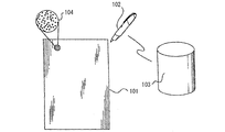
例えば、特許文献1には、図22に示すようなペンタブレット装置について開示されている。
図示されているように、紙101には、拡大部分104に図示されているようなランダムパターンが印刷されており、一方、ペン102にはカメラが備えられている。
上記構成によれば、ペン102によって、紙101に手書きで記録を残せるとともに、ペン102に備えられたカメラによって読み込まれたランダムパターンをペン102および外部装置103で解析し、上記ランダムパターンに対応した座標を検出し、電子化を行うようになっている。
しかしながら、図22に示す特許文献1に開示されている構成においては、紙101には、必ずランダムパターンが印刷されている必要がある。
したがって、ランダムパターンが印刷されている特殊な紙に手書きで記録を残せるとともに、電子化を行うことはできるが、ランダムパターンが印刷されてない一般的な紙やノートを用いた場合には、手書きで記録を残せたとしても、同時に電子化を行うことはできないという問題がある。
本発明は、上記の問題点に鑑みてなされたものであり、パターンなどが印刷されてない一般的な紙やノートを用いた場合においても、手書きで記録を残せると同時に電子化ができるペンタブレット装置と、上記ペンタブレット装置を備えたペンタブレットシステムとを提供することを目的とする。
本発明のペンタブレット装置は、上記の課題を解決するために、ペンと、台とを備え、上記ペンの先端の座標を検出できるペンタブレット装置であって、上記ペンの先端には、上記台上に置かれた被筆記部材と接触することにより、振動を伝える先端部材が設けられており、上記台の隅には、それぞれ独立した擬似ランダム信号を発信する振動発信子が3個以上設けられており、上記各々の振動発信子から発信された振動は、上記台および上記被筆記部材を介して、上記ペンの先端が上記被筆記部材と接触した際に、上記ペンに伝達され、上記ペンに備えられた振動検出子によって検出され、上記振動検出子によって検出された振動に基づいた各々の信号と、上記各々の独立した擬似ランダム信号との相関演算を行い、求めた上記各々の振動発信子からのそれぞれの遅延時間に基づいて、上記ペンの先端の座標を検出することを特徴としている。
上記構成によれば、上記ペンの先端には、上記被筆記部材と接触する先端部材が備えられてので、手書きで上記被筆記部材に記録を残すことができる。
そして、上記構成によれば、上記ペンの先端の座標は、それぞれ独立した擬似ランダム信号を発信する振動発信子から発信された振動を、上記ペンに備えられた振動検出子によって検出し、上記振動検出子によって検出された振動に基づいた信号と、上記複数の独立した擬似ランダム信号との相関演算を行い、求めた上記複数の振動発信子からのそれぞれの遅延時間に基づいて、検出され、電子化が行われるようになっている。
したがって、上記構成によれば、パターンなどが印刷されてない一般的な紙やノートなどの上記被筆記部材を用いた場合においても、手書きで記録を残せると同時に電子化ができるペンタブレット装置を実現することができる。
本発明のペンタブレット装置は、上記の課題を解決するために、ペンと、台とを備え、上記ペンの先端の座標を検出できるペンタブレット装置であって、上記ペンの先端には、上記台上に置かれた被筆記部材と接触することにより、振動を伝える先端部材が設けられており、上記台の隅には、それぞれ独立した擬似ランダム信号を発信する振動発信子が複数個設けられており、上記各々の振動発信子から発信された振動は、上記台および上記被筆記部材を介して、上記ペンの先端が上記被筆記部材と接触した際に、上記ペンに伝達され、上記ペンに備えられた振動検出子によって検出され、上記振動発信子のスタートパルス信号と上記振動検出子のスタートパルス信号とは、同期化されており、上記振動検出子によって検出された振動に基づいた各々の信号と、上記各々の独立した擬似ランダム信号との相関演算を行い、求めた上記各々の振動発信子からのそれぞれの遅延時間に基づいて、上記ペンの先端の座標を検出することを特徴としている。
上記構成によれば、上記振動発信子のスタートパルス信号と上記振動検出子のスタートパルス信号とは、同期化されているため、より少ない振動発信子を設けても上記ペンの先端の座標を検出することができる。
本発明のペンタブレットシステムは、上記の課題を解決するために、上記ペンタブレット装置と、上記ペンの先端の座標の情報を処理する処理装置とを備えたペンタブレットシステムであって、上記ペンタブレット装置に備えられたペンには、上記ペンの先端の座標の情報を送信する送信部が備えられており、上記処理装置には、上記送信部によって送信された上記ペンの先端の座標の情報を受信する受信部が備えられていることを特徴としている。
上記構成によれば、上記ペンタブレット装置に備えられたペンには、上記ペンの先端の座標の情報を送信する送信部が備えられており、上記処理装置には、上記送信部によって送信された上記ペンの先端の座標の情報を受信する受信部が備えられているので、上記ペンで検出された上記ペンの先端の座標の情報を上記処理装置に送ることができる。
本発明のペンタブレット装置は、以上のように、上記ペンの先端には、上記台上に置かれた被筆記部材と接触することにより、振動を伝える先端部材が設けられており、上記台の隅には、それぞれ独立した擬似ランダム信号を発信する振動発信子が複数個設けられており、上記各々の振動発信子から発信された振動は、上記台および上記被筆記部材を介して、上記ペンの先端が上記被筆記部材と接触した際に、上記ペンに伝達され、上記ペンに備えられた振動検出子によって検出され、上記振動検出子によって検出された振動に基づいた信号と、上記複数の独立した擬似ランダム信号との相関演算を行い、求めた上記複数の振動発信子からのそれぞれの遅延時間に基づいて、上記ペンの先端の座標を検出する構成である。
本発明のペンタブレット装置は、以上のように、上記ペンの先端には、上記台上に置かれた被筆記部材と接触することにより、振動を伝える先端部材が設けられており、上記台の隅には、それぞれ独立した擬似ランダム信号を発信する振動発信子が複数個設けられており、上記各々の振動発信子から発信された振動は、上記台および上記被筆記部材を介して、上記ペンの先端が上記被筆記部材と接触した際に、上記ペンに伝達され、上記ペンに備えられた振動検出子によって検出され、上記振動発信子のスタートパルス信号と上記振動検出子のスタートパルス信号とは、同期化されており、上記振動検出子によって検出された振動に基づいた各々の信号と、上記各々の独立した擬似ランダム信号との相関演算を行い、求めた上記各々の振動発信子からのそれぞれの遅延時間に基づいて、上記ペンの先端の座標を検出する構成である。
本発明のペンタブレットシステムは、以上のように、上記ペンタブレット装置と、上記ペンの先端の座標の情報を処理する処理装置とを備えたペンタブレットシステムであって、上記ペンタブレット装置に備えられたペンには、上記ペンの先端の座標の情報を送信する送信部が備えられており、上記処理装置には、上記送信部によって送信された上記ペンの先端の座標の情報を受信する受信部が備えられている構成である。
それゆえ、パターンなどが印刷されてない一般的な紙やノートを用いた場合においても、手書きで記録を残せると同時に電子化ができるペンタブレット装置と、上記ペンタブレット装置を備えたペンタブレットシステムとを実現することができる。
以下、図面に基づいて本発明の実施の形態について詳しく説明する。ただし、この実施の形態に記載されている構成部品の寸法、材質、形状、その相対配置などはあくまで一実施形態に過ぎず、これらによってこの発明の範囲が限定解釈されるべきではない。
〔実施の形態1〕
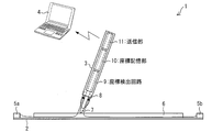
図1は、ペンタブレットシステム1の概略構成を示す図である。
図1は、ペンタブレットシステム1の概略構成を示す図である。
図示されているように、ペンタブレットシステム1には、超音波を伝える超音波伝達シート2(台)とペン3とホストコンピューター4(処理装置)とが備えられている。
そして、超音波伝達シート2の4隅のそれぞれには、4個の超音波発信子5a・5b・・・が備えられており、各々の超音波発信子5a・5b・・・は、詳しくは後述する4つの擬似ランダム信号発生回路(C/Aコード発生器)によって作られた4種の独立した疑似ランダム信号の各々で駆動されるようになっている。
また、超音波伝達シート2上には、例えば、紙や筆記ノートなどの被筆記部材6が乗せられている。
一方、ペン3の先端には、被筆記部材6と接触することにより、振動を伝える先端部材として、例えば、鉛筆芯やボールペン芯などの筆記部材7が設けられており、筆記部材7が被筆記部材6と接触することにより、被筆記部材6に筆跡を残すことができるようになっている。
そして、ペン3には、筆記部材7が設けられている箇所から所定距離離して、4個の超音波発信子5a・5b・・・から発信された超音波を検出するための超音波検出子8が設けられている。
なお、図示されているように、各々の超音波発信子5a・5b・・・から発信された超音波は、超音波伝達シート2および被筆記部材6を介して、ペン3の先端が被筆記部材6と接触した際に、ペン3に伝達され、ペン3に備えられた超音波検出子8(振動検出子)によって検出されるようになっている。
また、ペン3には、上記超音波を検出してペン3の先端の絶対座標を得るための座標検出回路9と、得られた座標列の情報を蓄積するための座標記憶部10(メモリ)と、得られた座標列の情報をホストコンピューター4に備えられた受信部(未図示)に送信するための送信部11とが備えられている。
図2は、図1に示したペンタブレットシステム1に備えられた超音波伝達シート2の平面図である。
図示されているように、超音波伝達シート2の4隅、すなわち、超音波伝達シート2の端部同士が交差する箇所には、超音波発信子5a・5b・5c・5dが取り付けられている。
各々の超音波発信子5a・5b・5c・5dは、詳しくは後述する4つの擬似ランダム信号発生回路(未図示)によって作られた4種の独立した疑似ランダム信号の各々で駆動されるようになっている。
以下、図3から図7に基づいて、擬似ランダム信号発生回路の概略的な構成について説明する。
先ずは、擬似乱数列の一種であるM系列(m-sequence)について、その発生方法および特性について説明する。
擬似ランダム数列とは、等確率性と無規則性を有するランダム数列のように見えるが、計算によって求めている数列であり、再現性のないランダム数列に対し、擬似ランダム数列は計算によって作られているので、再現できる周期性を有し、かつ、その作り方をわかれば、理論的な予測が可能である。
M系列(m-sequence)とは、線形最大周期列(Maximum-Length Linearly Recurring Sequence)の略である。
そして、M系列は、シフトレジスタと排他的論理和を用いて作ることができる。
図3は、図5と図6とに示す擬似ランダム信号発生回路14a・14b・14c・14dに備えられた第1シフトレジスタ12の一例を示す図である。
図示されているように、10段(10bit)の第1シフトレジスタ12とその3番目と10番目のフリップフロップのQ出力のXOR(排他的論理和)出力を、第1シフトレジスタ12の入力にフィードバックすることにより、周期210-1bitのM系列を発生することができる。
また、第1シフトレジスタ12はCKの立ち上がり入力ごとに図示されているシフト方向である右方向にシフトしていく。
図4は、図5と図6とに示す擬似ランダム信号発生回路14a・14b・14c・14dに備えられた第2シフトレジスタ13の一例を示す図である。
図示されているように、10段(10bit)の第2シフトレジスタ13とその2番目、3番目、6番目、8番目、9番目、10番目のフリップフロップのQ出力の全てのXOR(排他的論理和)をとり、第2シフトレジスタ13の入力にフィードバックすることにより、周期210-1bitのM系列を発生することができる。
また、第2シフトレジスタ13はCKの立ち上がり入力ごとに図示されているシフト方向である右方向にシフトしていく。
図5は、疑似ランダム信号を発生する疑似ランダム信号発生回路14aを示す図である。
図示されているように、疑似ランダム信号発生回路14aには、図3に示す第1シフトレジスタ12と、10個のフリップフロップのうちの2個のQ出力を選択するセレクターを備えた図4に示す第2シフトレジスタ13と、が備えられており、上記セレクターによって選択された2個のQ出力と第1シフトレジスタ12の最終段出力とのXOR(排他的論理和)を取り、Gi端子に出力するようになっている。
上記セレクターでの2個のQ出力端子(TAP番号)の選び方で、異なるGold系列(PRN系列)を得ることができる。
図5は、2番目のQ出力端子(TAP番号)と6番目のQ出力端子(TAP番号)とが選択された疑似ランダム信号発生回路14aを示しており、この場合においては、疑似ランダム信号としてPRN1系列を得ることができる。
そして、図示してないが、3番目のQ出力端子(TAP番号)と7番目のQ出力端子(TAP番号)とが選択された場合には、疑似ランダム信号としてPRN2系列を得ることができ、4番目のQ出力端子(TAP番号)と8番目のQ出力端子(TAP番号)とが選択された場合には、疑似ランダム信号としてPRN3系列を得ることができ、5番目のQ出力端子(TAP番号)と9番目のQ出力端子(TAP番号)とが選択された場合には、疑似ランダム信号としてPRN4系列を得ることができる。
以上のようにして、GPS(Global Positioning System)の規格で定義されている疑似ランダム信号発生回路を利用して、互いに独立なGold系列である210-1=1023クロック周期の疑似ランダム信号を得ることができる。
図6は、4隅に超音波発信子5a・5b・5c・5dが取り付けられている超音波伝達シート2と、超音波発信子5a・5b・5c・5dのそれぞれに互いに独立なGold系列である疑似ランダム信号を印加するための4個の疑似ランダム信号発生回路14a・14b・14c・14dと、を示す図である。
図示されているように、超音波伝達シート2の左上に設けられた超音波発信子5aには、図5に図示されている2番目のQ出力端子(TAP番号)と6番目のQ出力端子(TAP番号)とが選択された疑似ランダム信号発生回路14aで得られたPRN1系列の疑似ランダム信号が印加されるようになっている。
また、超音波伝達シート2の右上に設けられた超音波発信子5bには、3番目のQ出力端子(TAP番号)と7番目のQ出力端子(TAP番号)とが選択された疑似ランダム信号発生回路14bで得られたPRN2系列の疑似ランダム信号が印加されるようになっている。
また、超音波伝達シート2の右下に設けられた超音波発信子5cには、4番目のQ出力端子(TAP番号)と8番目のQ出力端子(TAP番号)とが選択された疑似ランダム信号発生回路14cで得られたPRN3系列の疑似ランダム信号が印加されるようになっている。
そして、超音波伝達シート2の左下に設けられた超音波発信子5dには、5番目のQ出力端子(TAP番号)と9番目のQ出力端子(TAP番号)とが選択された疑似ランダム信号発生回路14dで得られたPRN4系列の疑似ランダム信号が印加されるようになっている。
したがって、超音波発信子5a・5b・5c・5dからは、互いに独立した擬似ランダム信号の超音波が発信されるようになっている。
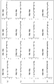
図7は、それぞれの疑似ランダム信号発生回路14a・14b・14c・14dで得られたPRN1系列・PRN2系列・PRN3系列・PRN4系列の疑似ランダム信号同士の相互相関を取った結果を示す図である。
図7の(a)は、PRN1系列の疑似ランダム信号とPRN1~4系列の疑似ランダム信号との相互相関を取った結果を示しており、図示されているように、PRN1系列の疑似ランダム信号は、PRN1系列以外、すなわち、PRN2~4系列の疑似ランダム信号とは充分独立している。
図7の(b)は、PRN2系列の疑似ランダム信号とPRN1~4系列の疑似ランダム信号との相互相関を取った結果を示しており、図示されているように、PRN2系列の疑似ランダム信号は、PRN2系列以外、すなわち、PRN1、3および4系列の疑似ランダム信号とは充分独立している。
図7の(c)は、PRN3系列の疑似ランダム信号とPRN1~4系列の疑似ランダム信号との相互相関を取った結果を示しており、図示されているように、PRN3系列の疑似ランダム信号は、PRN3系列以外、すなわち、PRN1、2および4系列の疑似ランダム信号とは充分独立している。
そして、図7の(d)は、PRN4系列の疑似ランダム信号とPRN1~4系列の疑似ランダム信号との相互相関を取った結果を示しており、図示されているように、PRN4系列の疑似ランダム信号は、PRN4系列以外、すなわち、PRN1~3系列の疑似ランダム信号とは充分独立している。
以上から、PRN1~4系列の疑似ランダム信号は、優れた自己相関特性を有するとともに、他の系列の疑似ランダム信号とは、充分独立していることがわかる。
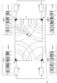
図8は、ペン3の先端が被筆記部材6と接触した際(筆記時)とペン3の先端が被筆記部材6と接触してない際(非筆記時)とにおいての超音波の伝達経路の差を示す図である。
図8の(a)は、ペン3で、超音波伝達シート2上に置かれているノートや原稿用紙などの被筆記部材6に筆記する際の超音波の伝達経路を示している。
先ず、超音波伝達シート2の4隅に設けられた超音波振動子5a・5b・5c・5dで発生した超音波は、超音波伝達シート2を伝導していく。
そして、超音波伝達シート2上には、ノートや原稿用紙などの被筆記部材6が置かれるが、ペン3で筆記している際には、例えば、鉛筆芯やボールペン芯などの筆記部材7が設けられているペン3の先端には、押し圧が加わっているので、被筆記部材6および筆記部材7を介して超音波伝達シート2の振動が、ペン3にまで伝わり、ペン3に備えられた超音波検出子8で、超音波振動子5a・5b・5c・5dで発生した超音波を充分なレベルで検出できるようになっている。
一方、図8の(b)は、ペン3で筆記しない際の超音波の伝達経路を示している。
ペン3で筆記しない際には、例えば、鉛筆芯やボールペン芯などの筆記部材7が設けられているペン3の先端には、押し圧が加わっていないので、超音波伝達シート2の振動は、ペン3の先端に備えられた筆記部材7に到達するまでに、著しく減衰してしまうため、ペン3に備えられた超音波検出子8では、超音波振動子5a・5b・5c・5dで発生した超音波をほとんど検出することはできないようになっている。
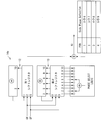
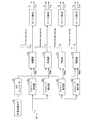
図9は、ペン3に備えられている座標検出回路9において、ペン3に備えられた超音波検出子8で得られた信号と既に上述したPRN1~4系列の疑似ランダム信号との相互相関を取り、ピークの相関値となる時間Ti(i=1~4)を求める部分の概略構成を示す図である。
図示されているように、超音波検出子8で検出された超音波は電気信号に変換され、A/Dコンバータ15に入力される。
そして、A/Dコンバータ15は、4つの相関器17a・17b・17c・17dそれぞれの入力端子に接続されており、4つのC/Aコード発生器16a・16b・16c・16dのそれぞれの出力は、4つの相関器17a・17b・17c・17dそれぞれの入力端子に接続されている。
なお、C/Aコード発生器16aは、図5に図示されている2番目のQ出力端子(TAP番号)と6番目のQ出力端子(TAP番号)とが選択された疑似ランダム信号発生回路14aと同じ構成であり、C/Aコード発生器16aから出力されたPRN1系列の疑似ランダム信号は、相関器17aに印加されるようになっている。
また、C/Aコード発生器16bは、3番目のQ出力端子(TAP番号)と7番目のQ出力端子(TAP番号)とが選択された疑似ランダム信号発生回路14bと同じ構成であり、C/Aコード発生器16bから出力されたPRN2系列の疑似ランダム信号は、相関器17bに印加されるようになっている。
また、C/Aコード発生器16cは、4番目のQ出力端子(TAP番号)と8番目のQ出力端子(TAP番号)とが選択された疑似ランダム信号発生回路14cと同じ構成であり、C/Aコード発生器16cから出力されたPRN3系列の疑似ランダム信号は、相関器17cに印加されるようになっている。
そして、C/Aコード発生器16dは、5番目のQ出力端子(TAP番号)と9番目のQ出力端子(TAP番号)とが選択された疑似ランダム信号発生回路14dと同じ構成であり、C/Aコード発生器16dから出力されたPRN4系列の疑似ランダム信号は、相関器17dに印加されるようになっている。
それから、各相関器17a・17b・17c・17dにおいては、スタートパルス信号SPが発生してから各相関器17a・17b・17c・17dにおいて相関値がピークとなるまでの時間Ti(i=1~4)を計測する。
また、ピークの相関値がある閾値を超えた時には、検出の有効性を示す検出有効フラグfl1~fl4を出力するようになっている。
以下、ピークの相関値となる時間Ti(i=1~4)および座標検出の計算方法について説明する。
超音波発信子5a・5b・5c・5dを出た疑似ランダム関数をm(t)とすると、超音波検出子8に現れる超音波振動U(t)は、下記式(1)によって表すことができる。

そして、上記式(1)に対して、m(t)との相関を取ると、下記式(2)のように表すことができる。

下記式(3)に示すように、m(t)の自己相関関数はディラック関数δ(τ)なので、超音波検出子8に現れる超音波振動U(t)とM系列の相関結果は下記式(4)式で与えられる。


上記式(1)、式(2)および式(4)において、(xi,yi)はi番目の超音波発信子の超音波伝達シート2上での座標であり、r0は超音波伝達シート2から超音波検出子8までの距離であり、cは超音波の速度、a0は超音波発信子5a・5b・5c・5dを駆動するスタートパルス信号とペン3内の相関器17a・17b・17c・17dのスタートパルス信号との時間差×超音波の速度である。
図10は、超音波伝達シート2の平面図を示しており、超音波発信子5a・5b・5c・5dのそれぞれの座標は、(x1、y1)、(x2、y2)、(x3、y3)および(x4、y4)となっている。
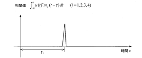
そして、図11に図示されているように、ペン3内の超音波検出子8で得られた信号U(t)と、それぞれに対応するGold系列mi(t)との相関を取り、ピークの相関値となる時間Ti(i=1~4)を求めた。
このようにして、ピークの相関値となる時間(遅延時間)Ti(i=1~4)に対して4つの下記式(5)が得られる。

未知数はx、yおよび(r0+a0)の3つなので、最小2乗法で座標を決定することができる。
なお、ペン3の先端に設けられた筆記部材7が、使用によってその長さが変わる鉛筆芯などである場合には、r0は未知数となるが、筆記部材7が、使用によってその長さが変わらないボールペン芯などである場合には、r0は設計値としておける。
本実施の形態においては、筆記部材7として使用によってその長さが変わらないボールペン芯を用いているが、依然a0は未知数であるため、以下では(r0+a0)を一つの未知数r0として扱う。
それから、上記式(5)における、Ti×cを疑似計測距離Riとおき、ニュートン法を用いて、上記式(5)における4つの式(i=1~4)より、真の座標を最小2乗法によって求める。
以下、ニュートン法を用いた計算方法について具体的に説明する。
先ず、上記式(5)における、Ti×cを疑似計測距離Riとおき、上記式(5)の偏分を求めると、下記式(6)が得られる。

そして、上記式(5)より下記式(7)および下記式(8)が得られる。


上記式(7)をαi、上記式(8)をβiとすると、下記式(9)のように表すことができる。ここで、εiはそれぞれの誤差である。

上記式(9)をベクトル形式で下記式(10)のように表すことができる。
R=A.X+E 式(10)
そして、fを2乗誤差の和として、上記式(10)を用いて表現すると、下記式(11)が得られる。
そして、fを2乗誤差の和として、上記式(10)を用いて表現すると、下記式(11)が得られる。
f=ET.E
=(R-A.X)T(R-A.X)
=RTR-2RTAX+XT(ATA)X 式(11)
上記式(11)が最小となるXを求めればよい。
=(R-A.X)T(R-A.X)
=RTR-2RTAX+XT(ATA)X 式(11)
上記式(11)が最小となるXを求めればよい。
なお、上付け添字Tは、転置行列を示す。
上記式(11)をXで偏分をとり0とおくことで、下記式(12)を得ることができる。
δf/δX=-2RT.A+2XT(ATA)=0 式(12)
そして、上記式(12)より、最終的に下記式(13)を得ることができる。
そして、上記式(12)より、最終的に下記式(13)を得ることができる。
X=(ATA)-1AT.R 式(13)
なお、上付け添字-1は、逆行列を示す。
なお、上付け添字-1は、逆行列を示す。
ニュートン法を用いた座標検出の計算手続きを説明すると以下のようになる。
先ず、4個の超音波発信子5a・5b・5c・5dの座標(xi,yi)(i=1~4)と、(x,y,r)の初期値(x0,y0,r0)を上記式(7)および上記式(8)に代入してαi,βiを求め、行列Aを求める。
それから、相関結果から求まった4つのTi値のそれぞれにcを掛けてRiとしてベクトルRを得る。
そして、このようにして求めた行列AとベクトルRから上記式(13)でXを求めることができる。
上記Xは、上記式(9)のΔx、Δy、Δrなので、初期値(x0,y0,r0)を(x0+Δx,y0+Δy,r0+Δr)と置き換えて、上記計算手続きを繰り返し、数回収束するまで計算を行い、収束した結果としてペン3の先端の座標(x,y,r)を得ることができる。
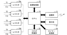
図12は、ペン3に備えられている、座標検出回路9におけるピークの相関値となる時間Tiに基づいてペン3の先端の座標を検出する部分と、座標記憶部10と、送信部11と、を示す図である。
図9に示すペン3に備えられている座標検出回路9において、ピークの相関値となる時間Ti(i=1~4)を求める部分から得られる時間Ti(i=1~4)のデータおよび検出の有効性を示す検出有効フラグfl1~fl4のデータは、図示されているように、演算処理回路のレジスタ18a・18b・18c・18dに格納される。
そして、レジスタ18a・18b・18c・18dは、IO端子を通してCPU19(処理部)に、接続されており、座標記憶部10は、バスを介してCPU19と接続されている。
また、CPU19には、IO端子を介して送信部11が接続されており、この他にも、詳しくは後述する各種ソフトウェアが貯蔵されているソフトウェア貯蔵部20が接続されている。
そして、CPU19には、実施の形態2において説明する表示部21が接続されていてもよい。
また、CPU19には、基準フレームを作り出すタイマー回路部24が接続されている。
図示されているように、レジスタ18a・18b・18c・18dに新しい計測値T1~T4が書き込まれ、検出フラグfl1~fl4が有効になると、CPU19は、上述したニュートン法を用いた座標検出の計算手続きを行い、フレーム毎にペン3の先端の座標(x,y)を計算するようになっている。
このように、フレーム毎に得られたペン3の先端の座標は、座標記憶部10に蓄積することができ、必要なタイミングに送信部11を介して、図1に示すような受信部を備えたホストコンピューター4に、フレーム毎に得られたペン3の先端の座標のデータを送ることができるようになっている。
なお、本実施の形態においては、ペン3に座標記憶部10および送信部11を備えた構成としているが、これに限定されることはなく、座標記憶部10が備えられてない構成においては、フレーム毎に得られたペン3の先端の座標のデータを一定間隔で送信部11を介して、ホストコンピューター4に送ればよい。また、送信部11が備えられてない構成においては、ペン3に例えば、USB端子などを設け、ペン3とホストコンピューター4とをケーブルで接続し、ペン3の先端の座標のデータをホストコンピューター4に取り出せるようにすればよい。
図13は、送信部11の代わりに出力回路30を備えているペン3aを備えたペンタブレットシステム1aの一例を示す図である。
図示されているように、ペン3aには、上述した図1に示す送信部11の代わりに出力回路30が備えられており、ペン3aに設けられたUSB端子にはケーブル31が接続され、さらに、ケーブル31はホストコンピューター4のUSB端子に接続されている。
したがって、図13に示すペンタブレットシステム1aにおいては、標記憶部10に蓄積されるペン3aの先端の座標のデータなどは、ペン3aに備えられた出力回路30からケーブル31を介してホストコンピューター4に送られるようになっている。
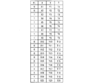
図14は、図1に示す座標記憶部10に蓄積されるペン3の先端の座標のデータおよび検出の有効性を示す検出有効フラグのデータの一例を示す図である。
図中のX、Yの欄は、図12に示すソフトウェア貯蔵部20に貯蔵されている座標復元アルゴリズムによって、CPU19で計算されたフレーム毎のXY座標である。
そして、FLの欄は検出の有効性を示す検出有効フラグを表わしており、非タッチで超音波検出子8に有効な信号が検出されなかった時は0で、座標が計算できた時は1である。
また、T欄は、フレームタイムを表している。
なお、本実施の形態においては、図2に図示されているように、超音波伝達シート2の端部同士が交差する4箇所に、4個の超音波発信子5a・5b・5c・5dを配置させた構成を用いているが、これに限定されることはなく、3個以上の超音波発信子を用いればよく、座標検出精度などを考慮し、その個数を適宜決めればよい。
さらには、ペン3の先端の座標を検出できるのであれば、例えば、実施の形態3で後述するように、2個の超音波発信子を用いることもできる。
以上のように、ペンタブレットシステム1においては、ペン3の先端の座標の検出に、疑似ランダム信号(Gold系列)で変調した独立した超音波信号を用いるので、4個の超音波発信子5a・5b・5c・5dから同時に超音波信号を発生しても、同時に4個の超音波発信子5a・5b・5c・5dからペン3の先端までのそれぞれの距離を計測できるようになっている。
また、ノートや原稿用紙などの被筆記部材6にペン3の先端が触れると初めて超音波がペン3内に伝導されるので、それを検出することによりタッチの有無を検出することできるようになっている。
したがって、上記構成によれば、ペン3の先端のタッチ有無を検出するための別途の検出手段を設ける必要はない。
また、上記構成によれば、ペン3の先端からペン3内に備えられた超音波検出子8までの距離は共通で、この距離は上述した式(5)にr0として含まれるので、ペン3の先端に備えられた筆記部材7が例えば、鉛筆芯などのように使用によって、削られる場合であっても、ペン3の先端のタッチしている位置の座標を精度高く算出することができる。
また、上記構成によれば、ペン3の先端に例えば、鉛筆芯やボールペン芯などの筆記部材7が付けられているため、従来の筆記具と同様に、手書き文字や手描き図形を紙ノートなどに残せると同時に、上記紙ノートなどに書かれた手書き文字や手描き図形と同じイメージの電子化を行うことができるようになっている。
したがって、上記紙ノートなどに書かれた手書き文字や手描き図形をあとで光学スキャナーにかける手間が不要になるので、特に、電子化の遅れているカルテや看護日誌などを被筆記部材6として用いることにより、非常に便利になる。
なお、本実施の形態においては、振動発信子として、超音波発信子を用いているが、ペン3の先端の座標を算出できるのであれば、これに限定されることはない。また、必要に応じて、光変調などの方法を用いてもよい。
なお、本実施の形態においては、被筆記部材6と接触することにより、振動を伝える先端部材として、例えば、鉛筆芯やボールペン芯などの筆記部材7をペン3の先端に設けているが、ペン3の先端に設けられる先端部材としては、被筆記部材6と接触することにより、振動を伝えることができ、手書きの記録を残すことができるのであれば、これらに限定されない。
〔実施の形態2〕
次に、図15から図18に基づいて、本発明の第2の実施形態について説明する。本実施の形態のペンタブレットシステムに備えられたペン3bには、表示部21とページ送りスイッチ&送信スイッチ22と、ページ戻しスイッチ23と、ペン3bの動きを認識し、ペン3bの動きの圧縮情報を生成するデータ圧縮部(未図示)と、が設けられている点において、実施の形態1とは異なっており、その他の構成については実施の形態1において説明したとおりである。説明の便宜上、上記の実施の形態1の図面に示した部材と同じ機能を有する部材については、同じ符号を付し、その説明を省略する。
次に、図15から図18に基づいて、本発明の第2の実施形態について説明する。本実施の形態のペンタブレットシステムに備えられたペン3bには、表示部21とページ送りスイッチ&送信スイッチ22と、ページ戻しスイッチ23と、ペン3bの動きを認識し、ペン3bの動きの圧縮情報を生成するデータ圧縮部(未図示)と、が設けられている点において、実施の形態1とは異なっており、その他の構成については実施の形態1において説明したとおりである。説明の便宜上、上記の実施の形態1の図面に示した部材と同じ機能を有する部材については、同じ符号を付し、その説明を省略する。
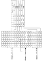
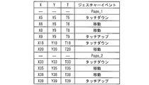
図15は、ペン3bの動き(ジェスチャー)を認識し、ペン3bの動きの圧縮情報を生成する、例えば、図12に示すCPU19内に設けることができるデータ圧縮部によって、図14に示す各フレーム毎の座標のデータおよび検出の有効性を示す検出有効フラグのデータから圧縮データを生成する場合を示す図である。
図示されているように、上記圧縮データは、図14に示す計算された座標列に対して、ペン3bの動き(ジェスチャー)認識を行い、ペン3bの先端がタッチしたというイベント(タッチダウン)、ペン3bの先端が非タッチにしたというイベント(タッチアップ)およびペン3bの先端が移動中であるというイベント(移動)などのジェスチャーイベント情報と併せて生成され、座標記憶部10に蓄積されるようになっている。
各フレーム毎にジェスチャーイベント情報があるが、ペン3bの動き(ジェスチャー)を認識することで、生成されるデータ量を圧縮することができる。
以下、ペン3bの動き(ジェスチャー)を認識することで、生成されるデータ量が圧縮される理由について例を挙げて説明する。
図15において、例えば、T3~T5のように、3フレーム連続して有効な座標が検出され、その座標の動きがある範囲内であれば、ペン3bの先端がタッチしたものとして、タッチダウンイベントとしてイベントを生成する。
そして、T5~T6にかけて、ペン3bの先端がある移動量以上動いた場合は、移動イベントを生成し、T6~T7にかけて、移動量が少ない場合は、スキップする。
また、T7~T8にかけて、ペン3bの先端がある移動量以上動いた場合は、再び移動イベントを生成する。
そして、T10~T12のように、3フレーム連続して有効な座標が検出されなかった場合には、T9において、ペン3bがアップしたとしてタッチアップイベントを生成する。
また、T16~T18のように、3フレーム連続して有効な座標が検出され、その座標の動きがある範囲内であれば、ペン3bの先端がタッチしたものとして、タッチダウンイベントとしてイベントを再び生成する。
それから、T19~T20にかけて、ペン3bの先端がある移動量以上動いた場合は、移動イベントを再び生成する。
以上のように、ペン3bの動き(ジェスチャー)を認識することで、図14に示す各フレーム毎の座標のデータおよび検出の有効性を示す検出有効フラグのデータを、図15に図示されているように、座標データ、フレームタイムおよびジェスチャーイベント(ジェスチャーコード)のデータとして、ペン3bの動きの圧縮データを得ることができ、この圧縮データを座標記憶部10に蓄積することができる。
図16は、本実施の形態のペンタブレットシステムにおいて用いられているペン3bの外観を示す図である。
図示されているように、ペン3bにおいて、筆記部材7が設けられる先端部と、反対方向には、ページ送りスイッチ&送信スイッチ22が設けられている。
そして、その横にはさらにページ戻しスイッチ23と現在のページを示す表示部21とが配置されている。
ページ送り&送信スイッチ22を短い時間押すと、現在のページ(Page2)がインクリメントされ、表示部21上に表示されるようになっている。
そして、同時に、図17に図示されているように、図15で説明したジェスチャーイベントのあとに、新しいページNoとして、Page_2のイベント情報が追加されるようになっている。
また、ページ戻しスイッチ23を短い時間押すと、現在のページ(Page2)がデクリメントされて、表示部21上に表示されるとともに、例えば、ページ(Page2)に記録をしていても、一旦前のページ(Page1)に戻って手書きで上書き記録をすることができる。
また、新しいページNoに記録した座標データを全て消したい時は、ページ送り&送信スイッチ22とページ戻しスイッチ23を同時に長押し(例えば、2秒以上)することで、対象のページNoのデータを全て消去することもできる。
以上のような、ページNoのイベント情報が追加され、座標記憶部10に蓄積されている圧縮データは、ページ送り&送信スイッチ22を少し長い時間押す(例えば、2秒以上)と、CPU19によって、送信部11を介して、例えば、外部機器である受信部を備えたホストコンピューター4に送信されるようになっている。
そして、上記圧縮データを受信したホストコンピューター4は、圧縮された座標データとイベント情報のデータとを順序に従って、各ページ毎に復元することで、ペン3bを用いて手書きで書いたイメージを、そのままホストコンピューター4のメモリに展開し、ホストコンピューター4に備えられた表示部に表示することができるようになっている。
上記構成によれば、ページ送り&送信スイッチ22を長押しするだけで、ペン3bで書いた軌跡を、ホストコンピューター4に備えられた表示部で見ることができるようになっている。
また、上記構成によれば、ペン3bの先端に例えば、鉛筆芯やボールペン芯などの筆記部材7が付けられているため、従来の筆記具と同様に、手書き文字や手描き図形を紙ノートなどに残せると同時に、上記紙ノートなどに書かれた手書き文字や手描き図形と同じイメージの電子化を行うことができるようになっている。
したがって、上記紙ノートなどに書かれた手書き文字や手描き図形をあとで光学スキャナーにかける手間が不要になるので、特に、電子化の遅れているカルテや看護日誌などを被筆記部材6として用いることにより、非常に便利になる。
なお、本実施の形態においては、ページNoのイベント情報とジェスチャーイベント情報の両方が追加された場合を例に挙げて説明したが、これに限定されることはなく、ページNoのイベント情報およびジェスチャーイベント情報中、何れか一方のみが追加されるような構成としてもよい。
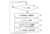
図18は、本実施の形態のペンタブレットシステムのペン3bに備えられたCPUのメインプログラムのフローチャートを示す図である。
図示されているように、プログラムステップは、フレーム検出(S1)、4つの相関値より座標計算(S2)、ジェスチャー認識(S3)、ジェスチャーコード&座標&フレームタイムの記憶(S4)およびスイッチ検出及び動作処理(S5)のステップからなり、これらのフローはフレーム時間に同期して実行されるようになっている。
以下、上記各ステップについて説明する。
フレーム検出ステップ(S1)においては、メインプログラムでは、フレーム信号(CPU内のタイマー発生回路より発生し、通常は0で1フレーム時間経過すると1になり、再び0に戻る信号)をチェックし、先ず、フレーム信号が0であれば再度フレーム信号をチェックする。フレーム信号が1になった段階で「フレームを検出した」と判断して次のステップに進む。
そして、4つの相関値より座標計算ステップ(S2)においては、レジスタ18a・18b・18c・18d(図12参照)に記憶されている4つの相関値から上記アルゴリズムに従って座標を算出する。
また、ジェスチャー認識ステップ(S3)においては、上記検出した座標と、過去に検出した座標とフレームタイムにより、「タッチアップ」、「タッチダウン」、「移動」などのジェスチャー認識を行う。
それから、ジェスチャーコード(ジェスチャーイベント)&座標&フレームタイムの記憶ステップ(S4)においては、図15に図示されているような上記ジェスチャー認識で認識されたジェスチャーの種類や座標、フレーム情報を座標記憶部10に記憶する。
最後に、スイッチ検出及び動作処理ステップ(S5)においては、ページ送りスイッチ&送信スイッチ22やページ戻しスイッチ23中、どのスイッチが押されているかを検出し、上述したそれぞれのスイッチが押された場合における動作状態に切り替える。
〔実施の形態3〕
次に、図19から図21に基づいて、本発明の第3の実施形態について説明する。本実施の形態のペンタブレットシステムに備えられた超音波伝達シート2aには、2個の超音波発信子5a・5bと、ペン3cに備えられた超音波検出子8との同期をとるため、スタートパルス変調回路40および送信回路41とが設けられており、一方、ペン3cには、超音波発信子5a・5bとの同期をとるため、受信回路42および同期検出回路43が設けられている点において、実施の形態1とは異なっており、その他の構成については実施の形態1において説明したとおりである。説明の便宜上、上記の実施の形態1の図面に示した部材と同じ機能を有する部材については、同じ符号を付し、その説明を省略する。
次に、図19から図21に基づいて、本発明の第3の実施形態について説明する。本実施の形態のペンタブレットシステムに備えられた超音波伝達シート2aには、2個の超音波発信子5a・5bと、ペン3cに備えられた超音波検出子8との同期をとるため、スタートパルス変調回路40および送信回路41とが設けられており、一方、ペン3cには、超音波発信子5a・5bとの同期をとるため、受信回路42および同期検出回路43が設けられている点において、実施の形態1とは異なっており、その他の構成については実施の形態1において説明したとおりである。説明の便宜上、上記の実施の形態1の図面に示した部材と同じ機能を有する部材については、同じ符号を付し、その説明を省略する。
図19は、本実施の形態のペンタブレットシステムに備えられた超音波伝達シート2aおよびペン3cの概略構成を示す図である。
図示されているように、超音波伝達シート2aの左上には、超音波発信子5aが取り付けられており、超音波伝達シート2aの右上には、超音波発信子5bが取り付けられている。
そして、各々の超音波発信子5a・5bは、2つの擬似ランダム信号発生回路14a・14bによって作られた2種の独立した疑似ランダム信号の各々で駆動されるようになっている。
図示されているように、超音波発信子5aには、図5に図示されている2番目のQ出力端子(TAP番号)と6番目のQ出力端子(TAP番号)とが選択された疑似ランダム信号発生回路14aで得られたPRN1系列の疑似ランダム信号が印加されるようになっている。
また、超音波発信子5bには、3番目のQ出力端子(TAP番号)と7番目のQ出力端子(TAP番号)とが選択された疑似ランダム信号発生回路14bで得られたPRN2系列の疑似ランダム信号が印加されるようになっている。
そして、超音波伝達シート2aには、ペン3cに備えられた超音波検出子8との同期をとるため、同期信号を作り出すスタートパルス変調回路40および上記同期信号を電波として、ペン3cに備えられた座標検出回路9の受信回路42に送信する送信回路41とが備えられている。
なお、本実施の形態においては、筆記部材7として使用によってその長さが変わらないボールペン芯を用いているが、これに限定されることはなく、使用によってその長さが変わる鉛筆芯などを用いることもできる。
図20は、ペン3cに備えられている座標検出回路9において、ペン3cに備えられた超音波検出子8で得られた信号と既に上述したPRN1~2系列の疑似ランダム信号との相互相関を取り、ピークの相関値となる時間Ti(i=1、2)を求める部分の概略構成を示す図である。
図示されているように、A/Dコンバータ15は、2つの相関器17a・17bそれぞれの入力端子に接続されており、2つのC/Aコード発生器16a・16bのそれぞれの出力は、2つの相関器17a・17bそれぞれの入力端子に接続されている。
なお、C/Aコード発生器16aは、図5に図示されている2番目のQ出力端子(TAP番号)と6番目のQ出力端子(TAP番号)とが選択された疑似ランダム信号発生回路14aと同じ構成であり、C/Aコード発生器16aから出力されたPRN1系列の疑似ランダム信号は、相関器17aに印加されるようになっている。
また、C/Aコード発生器16bは、3番目のQ出力端子(TAP番号)と7番目のQ出力端子(TAP番号)とが選択された疑似ランダム信号発生回路14bと同じ構成であり、C/Aコード発生器16bから出力されたPRN2系列の疑似ランダム信号は、相関器17bに印加されるようになっている。
そして、ペン3cに備えられている座標検出回路9aには、超音波発信子5a・5bとの同期をとるため、超音波伝達シート2aに備えられた送信回路41から送信される同期信号としての電波を受信する受信回路42と上記同期信号を検出する同期検出回路43とが備えられている。
それから、同期検出回路43において、同期信号が検出された際には、スタートパルス信号SPが発生され、各相関器17a・17bにおいては、スタートパルス信号SPが発生してから各相関器17a・17bにおいて相関値がピークとなるまでの時間Ti(i=1、2)を計測する。
以下、本実施の形態における、ピークの相関値となる時間Ti(i=1、2)および座標を検出する計算方法について説明する。
本実施の形態においては、筆記部材7として使用によってその長さが変わらないボールペン芯を用いているので、ペン3cの先端から超音波検出子8までの距離を固定値とみなすことができ、さらに、超音波発信子5a・5bと超音波検出子8との同期がとれているため、超音波伝達シート2aに2個の超音波発信子5a・5bのみを設けた場合であっても、ペン3cの先端の座標を検出することができるようになっている。
超音波発信子5a・5bと超音波検出子8との同期がとれている場合においては、実施の形態1において既に説明した式(1)、式(2)および式(4)において、a0は0となる。そして、ペン3cの先端から超音波検出子8までの距離を固定値とみなすことができるので、r0は固定値となる。
図21は、超音波伝達シート2aの平面図を示しており、超音波発信子5a・5bのそれぞれの座標は、(x1、y1)および(x2、y2)となっている。
そして、実施の形態1と同様に、ペン3c内の超音波検出子8で得られた信号U(t)と、それぞれに対応するGold系列mi(t)との相関を取り、ピークの相関値となる時間(遅延時間)Ti(i=1、2)を求めた。
このようにして、ピークの相関値となる時間Ti(i=1、2)に対して2つの下記式(14)が得られる。

未知数はx、yの2つなので、最小2乗法で座標を決定することができる。
それから、上記式(14)における、Ti×cを疑似計測距離Riとおき、ニュートン法を用いて、上記式(14)における2つの式(i=1、2)より、真の座標を最小2乗法によって求める。
以下、ニュートン法を用いた計算方法について具体的に説明する。
先ず、上記式(14)における、Ti×cを疑似計測距離Riとおき、上記式(14)の偏分を求めると、下記式(15)が得られる。

そして、上記式(14)より下記式(16)および下記式(17)が得られる。


上記式(16)をαi、上記式(17)をβiとすると、下記式(18)のように表すことができる。ここで、εiはそれぞれの誤差である。

上記式(18)をベクトル形式で下記式(19)のように表すことができる。
R=A.X+E 式(19)
そして、fを2乗誤差の和として、上記式(19)を用いて表現すると、下記式(20)が得られる。
そして、fを2乗誤差の和として、上記式(19)を用いて表現すると、下記式(20)が得られる。
f=ET.E
=(R-A.X)T(R-A.X)
=RTR-2RTAX+XT(ATA)X 式(20)
上記式(20)が最小となるXを求めればよい。
=(R-A.X)T(R-A.X)
=RTR-2RTAX+XT(ATA)X 式(20)
上記式(20)が最小となるXを求めればよい。
なお、上付け添字Tは、転置行列を示す。
上記式(20)をXで偏分をとり0とおくことで、下記式(21)を得ることができる。
δf/δX=-2RT.A+2XT(ATA)=0 式(21)
そして、上記式(21)より、最終的に下記式(22)を得ることができる。
そして、上記式(21)より、最終的に下記式(22)を得ることができる。
X=(ATA)-1AT.R 式(22)
なお、上付け添字-1は、逆行列を示す。
なお、上付け添字-1は、逆行列を示す。
ニュートン法を用いた座標検出の計算手続きを説明すると以下のようになる。
先ず、2個の超音波発信子5a・5bの座標(xi,yi)(i=1、2)と、(x,y)の初期値(x0,y0)を上記式(16)および上記式(17)に代入してαi,βiを求め、行列Aを求める。
それから、相関結果から求まった2つのTi値のそれぞれにcを掛けてRiとしてベクトルRを得る。
そして、このようにして求めた行列AとベクトルRから上記式(22)でXを求めることができる。
上記Xは、上記式(18)のΔx、Δyなので、初期値(x0,y0)を(x0+Δx,y0+Δy)と置き換えて、上記計算手続きを繰り返し、数回収束するまで計算を行い、収束した結果としてペン3cの先端の座標(x,y)を得ることができる。
なお、本実施の形態においては、2個の超音波発信子を用いているが、その個数は2個以上であれば特に限定されることはなく、座標検出精度などを考慮し、その個数を適宜決めればよい。
本発明のペンタブレット装置の上記台において、端部同士が交差する箇所には、上記振動発信子が設けられていることが好ましい。
上記構成によれば、少ない数の上記振動発信子を用いたとしても、精度高く上記ペンの先端の座標を検出することができる。
本発明のペンタブレット装置において、上記振動発信子は、超音波発信子であり、上記振動検出子は、超音波検出子であることが好ましい。
上記構成によれば、超音波を用いて上記ペンの先端の座標を検出するようになっているため、精度および信頼性が高いペンタブレット装置を実現することができる。
本発明のペンタブレット装置において上記ペンには、上記ペンの先端の座標の情報を蓄積できるメモリが備えられていることが好ましい。
上記構成によれば、上記ペンには、上記ペンの先端の座標の情報を蓄積できるメモリが備えられているので、上記ペンから上記ペンの先端の座標の情報を必要な場合に外部に取り出して使用することができる。
本発明のペンタブレット装置において上記ペンには、上記ペンの先端の座標の情報を上記メモリに蓄積するための処理部が備えられていることが好ましい。
本発明のペンタブレット装置において上記ペンの先端の座標の情報には、上記ペンの先端が上記被筆記部材に接触したかに関する情報が含まれており、上記ペンの処理部には、上記ペンの先端が上記被筆記部材に接触したかに関する情報および/または上記ペンの先端の座標の変化量に基づいて、上記ペンの動きを認識し、上記ペンの動きの圧縮情報を生成するデータ圧縮部が備えられており、上記データ圧縮部によって生成された圧縮情報が、上記メモリに蓄積されることが好ましい。
上記構成によれば、上記ペンの処理部には、上記ペンの動きを認識し、上記ペンの動きの圧縮情報を生成するデータ圧縮部が備えられており、上記データ圧縮部によって生成された圧縮情報が、上記メモリに蓄積されるので、上記ペンの先端の座標の情報をより少ない量で上記メモリに蓄積することができる。
本発明のペンタブレット装置において上記ペンには、ページ送りスイッチが備えられており、上記ページ送りスイッチを押す毎に、上記処理部によって、得られた上記ペンの先端の座標の情報の最後に、新たなページ情報が加えられることが好ましい。
上記構成によれば、上記台上に置かれた被筆記部材である、例えば、紙やノートのページが変わる毎にページ送りスイッチを押すことによって、上記ペンの先端の座標の情報をページ毎に蓄積することができる。
本発明のペンタブレット装置において上記ペンには、ページ戻しスイッチが備えられており、上記ページ戻しスイッチを押すと、上記処理部によって、現ページより前の前ページに該当する上記ペンの先端の座標の情報に新たな上記ペンの先端の座標が加えられることが好ましい。
上記構成によれば、現ページより前の前ページに該当する上記ペンの先端の座標の情報に新たな上記ペンの先端の座標を加えることができるので、前ページへの追加記載が容易となる。
本発明のペンタブレット装置において上記ペンには、上記処理部によって、現ページに該当する上記ペンの先端の座標の情報を、上記メモリから削除するスイッチが備えられていることが好ましい。
上記構成によれば、上記スイッチを押すことで、手書きで記録を残す途中に誤りが生じても、この誤りが生じたページ分の上記ペンの先端の座標の情報を上記メモリから削除することができる。
本発明のペンタブレット装置において上記ペンには、上記ページを表示するための表示部が備えられていることが好ましい。
上記構成によれば、上記ペンの表示部には、現在のページが表示されるので、例えば、紙やノートのページが変わる毎にページ送りスイッチを押し忘れるのを防止することができる。
本発明のペンタブレット装置において上記先端部材は、上記被筆記部材に筆跡を残すことができる筆記部材であることが好ましい。
上記構成によれば、上記ペンの先端には、上記台上に置かれた、例えば、紙やノートなどの被筆記部材と接触することにより、上記被筆記部材に筆跡を残すことができるように、例えば、鉛筆芯やボールペン芯などの筆記部材が設けられているため、手書きで上記被筆記部材に記録を残すことができる。
本発明のペンタブレットシステムにおいて上記ペンには、上記ペンの先端の座標の情報を蓄積できるメモリと上記ペンの先端の座標の情報を送信するための送信スイッチとが備えられており、上記送信スイッチを押すことにより、上記ペンの先端の座標の情報が上記送信部から送信されることが好ましい。
上記構成によれば、上記ペンには、上記ペンの先端の座標の情報を蓄積できるメモリと上記ペンの先端の座標の情報を送信するための送信スイッチとが備えられているため、必要な場合にのみ上記送信スイッチを押すことにより、上記ペンで検出された上記ペンの先端の座標の情報を上記処理装置に送ることができる。
本発明のペンタブレットシステムにおいて上記処理装置には、表示部が備えられていることが好ましい。
上記構成によれば、上記ペンで検出された上記ペンの先端の座標の情報に基づいたイメージを上記処理装置に備えられた表示部を介して、確認することができる。
本発明は、例えば、ペンの先端の座標を検出できるペンタブレット装置や上記ペンタブレット装置を備えたペンタブレットシステムなどに好適に用いることができる。
1 ペンタブレットシステム
2、2a 超音波伝達シート(台)
3、3a、3b、3c ペン
4 ホストコンピューター(処理装置)
5a、5b、5c、5d 超音波発信子(振動発信子)
6 被筆記部材
7 筆記部材(先端部材)
8 超音波検出子(振動検出子)
9 座標検出回路
10 座標記憶部(メモリ)
11 送信部
12 第1シフトレジスタ
13 第2シフトレジスタ
14a、14b、14c、14d 疑似ランダム信号発生回路
15 A/Dコンバータ
16a、16b、16c、16d C/Aコード発生器
17a、17b、17c、17d 相関器
18a、18b、18c、18d レジスタ
19 CPU(処理部)
20 ソフトウェア貯蔵部
21 表示部
22 ページ送り&送信スイッチ
23 ページ戻しスイッチ
24 タイマー回路部
2、2a 超音波伝達シート(台)
3、3a、3b、3c ペン
4 ホストコンピューター(処理装置)
5a、5b、5c、5d 超音波発信子(振動発信子)
6 被筆記部材
7 筆記部材(先端部材)
8 超音波検出子(振動検出子)
9 座標検出回路
10 座標記憶部(メモリ)
11 送信部
12 第1シフトレジスタ
13 第2シフトレジスタ
14a、14b、14c、14d 疑似ランダム信号発生回路
15 A/Dコンバータ
16a、16b、16c、16d C/Aコード発生器
17a、17b、17c、17d 相関器
18a、18b、18c、18d レジスタ
19 CPU(処理部)
20 ソフトウェア貯蔵部
21 表示部
22 ページ送り&送信スイッチ
23 ページ戻しスイッチ
24 タイマー回路部
Claims (15)
- ペンと、台とを備え、
上記ペンの先端の座標を検出できるペンタブレット装置であって、
上記ペンの先端には、上記台上に置かれた被筆記部材と接触することにより、振動を伝える先端部材が設けられており、
上記台の隅には、それぞれ独立した擬似ランダム信号を発信する振動発信子が3個以上設けられており、
上記各々の振動発信子から発信された振動は、上記台および上記被筆記部材を介して、上記ペンの先端が上記被筆記部材と接触した際に、上記ペンに伝達され、上記ペンに備えられた振動検出子によって検出され、
上記振動検出子によって検出された振動に基づいた各々の信号と、上記各々の独立した擬似ランダム信号との相関演算を行い、求めた上記各々の振動発信子からのそれぞれの遅延時間に基づいて、上記ペンの先端の座標を検出することを特徴とするペンタブレット装置。 - 上記台において、端部同士が交差する箇所には、上記振動発信子が設けられていることを特徴とする請求項1に記載のペンタブレット装置。
- 上記振動発信子は、超音波発信子であり、
上記振動検出子は、超音波検出子であることを特徴とする請求項1または2に記載のペンタブレット装置。 - 上記ペンには、上記ペンの先端の座標の情報を蓄積できるメモリが備えられていることを特徴とする請求項1から3の何れか1項に記載のペンタブレット装置。
- 上記ペンには、上記ペンの先端の座標の情報を上記メモリに蓄積するための処理部が備えられていることを特徴とする請求項4に記載のペンタブレット装置。
- 上記ペンの先端の座標の情報には、上記ペンの先端が上記被筆記部材に接触したかに関する情報が含まれており、
上記ペンの処理部には、上記ペンの先端が上記被筆記部材に接触したかに関する情報および/または上記ペンの先端の座標の変化量に基づいて、上記ペンの動きを認識し、上記ペンの動きの圧縮情報を生成するデータ圧縮部が備えられており、
上記データ圧縮部によって生成された圧縮情報が、上記メモリに蓄積されることを特徴とする請求項5に記載のペンタブレット装置。 - 上記ペンには、ページ送りスイッチが備えられており、上記ページ送りスイッチを押す毎に、上記処理部によって、得られた上記ペンの先端の座標の情報の最後に、新たなページ情報が加えられることを特徴とする請求項5または6に記載のペンタブレット装置。
- 上記ペンには、ページ戻しスイッチが備えられており、上記ページ戻しスイッチを押すと、上記処理部によって、現ページより前の前ページに該当する上記ペンの先端の座標の情報に新たな上記ペンの先端の座標が加えられることを特徴とする請求項5から7の何れか1項に記載のペンタブレット装置。
- 上記ペンには、上記処理部によって、現ページに該当する上記ペンの先端の座標の情報を、上記メモリから削除するスイッチが備えられていることを特徴とする請求項5から8の何れか1項に記載のペンタブレット装置。
- 上記ペンには、上記ページを表示するための表示部が備えられていることを特徴とする請求項7から9の何れか1項に記載のペンタブレット装置。
- ペンと、台とを備え、
上記ペンの先端の座標を検出できるペンタブレット装置であって、
上記ペンの先端には、上記台上に置かれた被筆記部材と接触することにより、振動を伝える先端部材が設けられており、
上記台の隅には、それぞれ独立した擬似ランダム信号を発信する振動発信子が複数個設けられており、
上記各々の振動発信子から発信された振動は、上記台および上記被筆記部材を介して、上記ペンの先端が上記被筆記部材と接触した際に、上記ペンに伝達され、上記ペンに備えられた振動検出子によって検出され、
上記振動発信子のスタートパルス信号と上記振動検出子のスタートパルス信号とは、同期化されており、
上記振動検出子によって検出された振動に基づいた各々の信号と、上記各々の独立した擬似ランダム信号との相関演算を行い、求めた上記各々の振動発信子からのそれぞれの遅延時間に基づいて、上記ペンの先端の座標を検出することを特徴とするペンタブレット装置。 - 上記先端部材は、上記被筆記部材に筆跡を残すことができる筆記部材であることを特徴とする請求項1から11の何れか1項に記載のペンタブレット装置。
- 請求項1から12の何れか1項に記載のペンタブレット装置と、上記ペンの先端の座標の情報を処理する処理装置とを備えたペンタブレットシステムであって、
上記ペンタブレット装置に備えられたペンには、上記ペンの先端の座標の情報を送信する送信部が備えられており、
上記処理装置には、上記送信部によって送信された上記ペンの先端の座標の情報を受信する受信部が備えられていることを特徴とするペンタブレットシステム。 - 上記ペンには、上記ペンの先端の座標の情報を蓄積できるメモリと上記ペンの先端の座標の情報を送信するための送信スイッチとが備えられており、
上記送信スイッチを押すことにより、上記ペンの先端の座標の情報が上記送信部から送信されることを特徴とする請求項13に記載のペンタブレットシステム。 - 上記処理装置には、表示部が備えられていることを特徴とする請求項13または14に記載のペンタブレットシステム。
Priority Applications (1)
| Application Number | Priority Date | Filing Date | Title |
|---|---|---|---|
| US13/985,668 US20130321348A1 (en) | 2011-02-25 | 2012-02-21 | Pen tablet device, and pen tablet system |
Applications Claiming Priority (2)
| Application Number | Priority Date | Filing Date | Title |
|---|---|---|---|
| JP2011040635 | 2011-02-25 | ||
| JP2011-040635 | 2011-02-25 |
Publications (1)
| Publication Number | Publication Date |
|---|---|
| WO2012115106A1 true WO2012115106A1 (ja) | 2012-08-30 |
Family
ID=46720883
Family Applications (1)
| Application Number | Title | Priority Date | Filing Date |
|---|---|---|---|
| PCT/JP2012/054132 Ceased WO2012115106A1 (ja) | 2011-02-25 | 2012-02-21 | ペンタブレット装置およびペンタブレットシステム |
Country Status (2)
| Country | Link |
|---|---|
| US (1) | US20130321348A1 (ja) |
| WO (1) | WO2012115106A1 (ja) |
Cited By (1)
| Publication number | Priority date | Publication date | Assignee | Title |
|---|---|---|---|---|
| WO2017022089A1 (ja) * | 2015-08-04 | 2017-02-09 | 株式会社ワコム | ユーザ通知方法、手書きデータ取り込み装置、及びプログラム |
Families Citing this family (3)
| Publication number | Priority date | Publication date | Assignee | Title |
|---|---|---|---|---|
| US9720521B2 (en) | 2014-02-21 | 2017-08-01 | Qualcomm Incorporated | In-air ultrasound pen gestures |
| TWI731650B (zh) * | 2020-04-15 | 2021-06-21 | 宏碁股份有限公司 | 觸控筆、觸控電子裝置與觸控系統 |
| WO2024127783A1 (ja) * | 2022-12-12 | 2024-06-20 | アルプスアルパイン株式会社 | スタイラスペン、及び、入力システム |
Citations (4)
| Publication number | Priority date | Publication date | Assignee | Title |
|---|---|---|---|---|
| JPS6237730A (ja) * | 1985-08-12 | 1987-02-18 | Hitachi Ltd | 超音波式タブレツトの座標位置検出方法 |
| JPH1139095A (ja) * | 1997-07-18 | 1999-02-12 | Canon Inc | プレゼンテーション装置、その方法、及びペン入力装置 |
| JP2006139643A (ja) * | 2004-11-15 | 2006-06-01 | Seiko Epson Corp | 情報入力装置 |
| WO2010010832A1 (ja) * | 2008-07-25 | 2010-01-28 | 日本電気株式会社 | 位置検出システム、送信装置、受信装置、位置検出方法、位置検出プログラム |
Family Cites Families (8)
| Publication number | Priority date | Publication date | Assignee | Title |
|---|---|---|---|---|
| JP3251489B2 (ja) * | 1996-02-16 | 2002-01-28 | シャープ株式会社 | 座標入力装置 |
| EP2056233B1 (en) * | 1999-12-23 | 2011-10-19 | Anoto AB | Information management system |
| US6703570B1 (en) * | 2000-05-10 | 2004-03-09 | International Business Machines Corporation | Digital pen using ultrasonic tracking |
| US20050024346A1 (en) * | 2003-07-30 | 2005-02-03 | Jean-Luc Dupraz | Digital pen function control |
| US20050125228A1 (en) * | 2003-12-08 | 2005-06-09 | Samuels Derrick D. | Digital electronic correction pen with audio pronunciation and spell check capabilities, with built-in memory. Also calculation processing... thereof... |
| JP2005335156A (ja) * | 2004-05-26 | 2005-12-08 | Matsushita Electric Ind Co Ltd | 表示システム及び電子黒板システム及び表示制御方法 |
| US7474983B2 (en) * | 2005-01-05 | 2009-01-06 | Massachusetts Institute Of Technology | Method for object identification and sensing in a bounded interaction space |
| US20080259033A1 (en) * | 2007-04-19 | 2008-10-23 | Songchun Mu | Book-notepad personal computing device |
-
2012
- 2012-02-21 WO PCT/JP2012/054132 patent/WO2012115106A1/ja not_active Ceased
- 2012-02-21 US US13/985,668 patent/US20130321348A1/en not_active Abandoned
Patent Citations (4)
| Publication number | Priority date | Publication date | Assignee | Title |
|---|---|---|---|---|
| JPS6237730A (ja) * | 1985-08-12 | 1987-02-18 | Hitachi Ltd | 超音波式タブレツトの座標位置検出方法 |
| JPH1139095A (ja) * | 1997-07-18 | 1999-02-12 | Canon Inc | プレゼンテーション装置、その方法、及びペン入力装置 |
| JP2006139643A (ja) * | 2004-11-15 | 2006-06-01 | Seiko Epson Corp | 情報入力装置 |
| WO2010010832A1 (ja) * | 2008-07-25 | 2010-01-28 | 日本電気株式会社 | 位置検出システム、送信装置、受信装置、位置検出方法、位置検出プログラム |
Non-Patent Citations (1)
| Title |
|---|
| SHIN'YA TAKAYAMA: "Passive Ultrasonic Pointing System Based on Three-Dimensional Location Estimation", PROCEEDINGS OF THE ENGINEERING SCIENCES SOCIETY CONFERENCE OF IEICE 2009, 1 September 2009 (2009-09-01), pages 152 * |
Cited By (4)
| Publication number | Priority date | Publication date | Assignee | Title |
|---|---|---|---|---|
| WO2017022089A1 (ja) * | 2015-08-04 | 2017-02-09 | 株式会社ワコム | ユーザ通知方法、手書きデータ取り込み装置、及びプログラム |
| JPWO2017022089A1 (ja) * | 2015-08-04 | 2018-05-31 | 株式会社ワコム | ユーザ通知方法、手書きデータ取り込み装置、及びプログラム |
| US10429963B2 (en) | 2015-08-04 | 2019-10-01 | Wacom Co., Ltd. | User notification method, handwritten data capture device, and program |
| US10754454B2 (en) | 2015-08-04 | 2020-08-25 | Wacom Co., Ltd. | User notification method, handwritten data capture device, and program |
Also Published As
| Publication number | Publication date |
|---|---|
| US20130321348A1 (en) | 2013-12-05 |
Similar Documents
| Publication | Publication Date | Title |
|---|---|---|
| US8086971B2 (en) | Apparatus, methods and computer program products providing finger-based and hand-based gesture commands for portable electronic device applications | |
| TW546582B (en) | Pointing device using two line-shaped image input devices and fingerprint to generate displacement signals | |
| CN102109923B (zh) | 指示体、位置检测装置以及位置检测方法 | |
| KR101489813B1 (ko) | 능동형 스타일러스 팬을 포함한 터치패널 및 그 제어방법 | |
| KR101651568B1 (ko) | 3차원 공간 인터페이스 장치 및 방법 | |
| EP1607852B1 (en) | Object position detector with edge motion feature and gesture recognition | |
| US8743061B2 (en) | Touch sensing method and electronic device | |
| US8743065B2 (en) | Method of identifying a multi-touch rotation gesture and device using the same | |
| TW200907770A (en) | Integrated touch pad and pen-based tablet input system | |
| CN103547988A (zh) | 选择用户界面的元素的方法以及实施该方法的装置 | |
| JP2004280834A (ja) | 仮想筆記平面を用いたモーション認識システム及びその認識方法 | |
| JP2010049583A (ja) | 腕時計型電子メモ装置 | |
| US20130033461A1 (en) | System for notetaking with source document referencing | |
| KR20020087993A (ko) | 정보 입력 장치 | |
| WO2012115106A1 (ja) | ペンタブレット装置およびペンタブレットシステム | |
| KR20110113157A (ko) | 전자 디바이스용 입력 방법 및 입력 디바이스, 이러한 방법을 수행하는 명령이 저장되어 있는 비일시적 컴퓨터 판독 가능 저장 매체 | |
| JP2001236174A (ja) | 手書き文字入力装置及び手書き文字認識方法 | |
| TW201234280A (en) | Hand-written character input device and portable terminal | |
| US20130033460A1 (en) | Method of notetaking using optically imaging pen with source document referencing | |
| US20130033429A1 (en) | Method of notetaking with source document referencing | |
| KR101019255B1 (ko) | 깊이 센서 방식의 공간 터치 무선단말기, 이의 데이터 처리방법 및 스크린장치 | |
| JP2023074558A (ja) | タッチ状態検出回路、タッチ状態検出回路を備える電子機器、及びタッチ状態検出方法 | |
| JP6048165B2 (ja) | コンピュータ装置、電子ペンシステム、及びプログラム | |
| CN102385449A (zh) | 便携式电子设备和触摸控制方法 | |
| TWI811909B (zh) | 觸控處理裝置與方法及觸控系統 |
Legal Events
| Date | Code | Title | Description |
|---|---|---|---|
| 121 | Ep: the epo has been informed by wipo that ep was designated in this application |
Ref document number: 12749566 Country of ref document: EP Kind code of ref document: A1 |
|
| WWE | Wipo information: entry into national phase |
Ref document number: 13985668 Country of ref document: US |
|
| NENP | Non-entry into the national phase |
Ref country code: DE |
|
| 122 | Ep: pct application non-entry in european phase |
Ref document number: 12749566 Country of ref document: EP Kind code of ref document: A1 |
|
| NENP | Non-entry into the national phase |
Ref country code: JP |