WO2012115085A1 - 油圧式オートテンショナ - Google Patents
油圧式オートテンショナ Download PDFInfo
- Publication number
- WO2012115085A1 WO2012115085A1 PCT/JP2012/054072 JP2012054072W WO2012115085A1 WO 2012115085 A1 WO2012115085 A1 WO 2012115085A1 JP 2012054072 W JP2012054072 W JP 2012054072W WO 2012115085 A1 WO2012115085 A1 WO 2012115085A1
- Authority
- WO
- WIPO (PCT)
- Prior art keywords
- sleeve
- cylinder
- oil passage
- oil
- hydraulic
- Prior art date
- Legal status (The legal status is an assumption and is not a legal conclusion. Google has not performed a legal analysis and makes no representation as to the accuracy of the status listed.)
- Ceased
Links
Images





Classifications
-
- F—MECHANICAL ENGINEERING; LIGHTING; HEATING; WEAPONS; BLASTING
- F16—ENGINEERING ELEMENTS AND UNITS; GENERAL MEASURES FOR PRODUCING AND MAINTAINING EFFECTIVE FUNCTIONING OF MACHINES OR INSTALLATIONS; THERMAL INSULATION IN GENERAL
- F16H—GEARING
- F16H7/00—Gearings for conveying rotary motion by endless flexible members
- F16H7/08—Means for varying tension of belts, ropes or chains
- F16H7/10—Means for varying tension of belts, ropes or chains by adjusting the axis of a pulley
- F16H7/12—Means for varying tension of belts, ropes or chains by adjusting the axis of a pulley of an idle pulley
- F16H7/1209—Means for varying tension of belts, ropes or chains by adjusting the axis of a pulley of an idle pulley with vibration damping means
- F16H7/1236—Means for varying tension of belts, ropes or chains by adjusting the axis of a pulley of an idle pulley with vibration damping means of the fluid and restriction type, e.g. dashpot
-
- F—MECHANICAL ENGINEERING; LIGHTING; HEATING; WEAPONS; BLASTING
- F16—ENGINEERING ELEMENTS AND UNITS; GENERAL MEASURES FOR PRODUCING AND MAINTAINING EFFECTIVE FUNCTIONING OF MACHINES OR INSTALLATIONS; THERMAL INSULATION IN GENERAL
- F16H—GEARING
- F16H7/00—Gearings for conveying rotary motion by endless flexible members
- F16H7/08—Means for varying tension of belts, ropes or chains
- F16H2007/0802—Actuators for final output members
- F16H2007/0806—Compression coil springs
-
- F—MECHANICAL ENGINEERING; LIGHTING; HEATING; WEAPONS; BLASTING
- F16—ENGINEERING ELEMENTS AND UNITS; GENERAL MEASURES FOR PRODUCING AND MAINTAINING EFFECTIVE FUNCTIONING OF MACHINES OR INSTALLATIONS; THERMAL INSULATION IN GENERAL
- F16H—GEARING
- F16H7/00—Gearings for conveying rotary motion by endless flexible members
- F16H7/08—Means for varying tension of belts, ropes or chains
- F16H7/0848—Means for varying tension of belts, ropes or chains with means for impeding reverse motion
- F16H2007/0859—Check valves
-
- F—MECHANICAL ENGINEERING; LIGHTING; HEATING; WEAPONS; BLASTING
- F16—ENGINEERING ELEMENTS AND UNITS; GENERAL MEASURES FOR PRODUCING AND MAINTAINING EFFECTIVE FUNCTIONING OF MACHINES OR INSTALLATIONS; THERMAL INSULATION IN GENERAL
- F16H—GEARING
- F16H7/00—Gearings for conveying rotary motion by endless flexible members
- F16H7/08—Means for varying tension of belts, ropes or chains
- F16H2007/0889—Path of movement of the finally actuated member
- F16H2007/0893—Circular path
Definitions
- the present invention relates to a hydraulic auto tensioner used for adjusting the tension of a belt for driving an automotive auxiliary machine such as an alternator, a water pump, and an air conditioner compressor.
- a swingable pulley arm 33 for supporting a tension pulley 32 is provided on the slack side of the belt 31, and the pulley arm The adjusting force of the hydraulic auto tensioner A is applied to 33 to urge the pulley arm 33 in a direction in which the tension pulley 32 presses the belt 31 so that the tension of the belt 31 is kept constant.
- Patent Document 1 As the hydraulic auto tensioner A used for the belt transmission as described above, the one described in Patent Document 1 has been conventionally known. 8 and 9 show the hydraulic auto tensioner described in Patent Document 1, in which a sleeve fitting hole 3 is provided on the upper surface of the bottom of the bottomed cylinder 1 filled with hydraulic oil, and the sleeve fitting hole 3 The lower portion of the rod 5 is slidably inserted into the sleeve 4 having the lower end inserted therein to form a pressure chamber 6 in the sleeve 4, and the spring seat 7 provided on the upper portion of the rod 5 and the bottom of the cylinder 1. A return spring 8 is incorporated between the upper surfaces to urge the rod 5 and the cylinder 1 in the extending direction.
- a cylindrical spring cover 11 covering the upper part of the return spring 8 is provided at the lower part of the spring seat 7 so that the inner periphery of the seal member 13 incorporated in the upper opening of the cylinder 1 is brought into elastic contact with the outer periphery of the spring cover 11.
- a reservoir chamber 14 sealed between the cylinder 1 and the sleeve 4 is formed, and the reservoir chamber 14 and the pressure chamber 6 are formed between the fitting surfaces of the sleeve fitting hole 3 and the sleeve 4 through an oil passage 15,
- a check valve 17 is incorporated in the lower end opening of the sleeve 4.
- the connecting piece 2 provided on the bottom lower surface of the cylinder 1 is rotatably connected to the engine block, and the connecting piece 9 provided on the upper surface of the spring seat 7 is shown in FIG.
- the check valve 17 is closed and the pressure chamber 6 is closed.
- the sealed hydraulic fluid is caused to flow through a minute gap 21 formed between the inner diameter surface of the sleeve 4 and the outer diameter surface of the rod 5, and a hydraulic damper force is generated in the pressure chamber 6 due to the viscous resistance of the hydraulic fluid at the time of the flow.
- the pushing force is buffered.
- hydraulic oil sealed in the cylinder 1 becomes too large, hydraulic oil may leak due to an increase in internal pressure due to an increase in ambient temperature when the auto tensioner contracts most.
- the amount of hydraulic oil sealed is set to less than 50% of the internal volume in the most contracted state of the auto tensioner in which the cylinder 1 and the rod 5 are relatively contracted relative to each other.
- the amount of hydraulic oil filled less than 50% substantially corresponds to 32% of the internal volume in the maximum extension state of the auto tensioner in which the cylinder 1 and the rod 5 are extended most.
- the inclination angle at the time of attachment is increased, and the oil level of the hydraulic oil is disposed below the upper opening 15c of the oil passage 15.
- the air in the reservoir chamber 14 is sucked into the pressure chamber 6 when the cylinder 1 and the rod 5 are extended, and the air is compressed when contracted, so that the hydraulic damper effect cannot be exhibited.
- the hydraulic auto tensioner needs to be assembled so that the oil level of the hydraulic oil is not disposed below the upper opening 15c of the oil passage 15 when used in an inclined manner.
- each oil passage 15 communicating with the pressure chamber 6 and the reservoir chamber 14 is arranged in a cross shape, and one of the two oil passages 15 arranged opposite to each other.
- a set passes through the center of the upper opening of the sleeve fitting hole 3 perpendicular to the axis of the sleeve 4 and extends in a radial direction xx (reference line xx) extending in a swingable direction of the auto tensioner.
- An object of the present invention is to provide a hydraulic auto tensioner capable of taking a large mounting inclination angle.
- a sleeve fitting hole is provided in the upper surface of the bottom of a bottomed cylinder filled with hydraulic oil, and the lower end is inserted into the sleeve fitting hole. Insert the lower end of the rod slidably to form a pressure chamber in the sleeve, and urge the cylinder and rod in the direction of extension between the spring seat provided on the upper part of the rod and the inner bottom surface of the cylinder.
- a return spring is installed, a cylindrical spring cover that covers the top of the return spring is provided on the spring seat, and the inner periphery of the seal member incorporated in the upper opening of the cylinder is brought into elastic contact with the outer periphery of the spring cover.
- An upper opening of a reservoir chamber formed between the cylinder and the sleeve is sealed, and the reservoir chamber and the pressure chamber are interposed between the fitting surfaces of the sleeve and the sleeve fitting hole.
- a communicating oil passage is provided, and a check valve is provided in the lower end of the sleeve that closes when the pressure in the pressure chamber becomes higher than the pressure in the reservoir chamber and shuts off the communication between the pressure chamber and the oil passage.
- the axial center of the sleeve A radial line extending in the swinging direction of the tensioner that can swing around the connecting portion and passing through the center of the upper opening of the sleeve fitting hole orthogonally with the reference line as a reference line, phase from the reference line to the circumferential direction A configuration is adopted in which the upper end opening of the oil passage is disposed at a position shifted.
- the oil passage may be composed of four oil passages arranged in a plane cross shape, or may be composed of two oil passages arranged opposite to each other.
- the number of oil passages is four
- the upper end opening of each oil passage is arranged at a position shifted by 45 ° in the circumferential direction with respect to the reference line, and the number of oil passages is two.
- the upper end opening of each oil passage is arranged at a position shifted by 90 ° in the circumferential direction with respect to the reference line.
- the reference line is a radial straight line that is orthogonal to the axis of the sleeve and extends in the swingable direction of the tensioner through the center of the upper opening of the sleeve fitting hole.
- the auto tensioner is installed. Therefore, it is possible to provide an auto tensioner that is less subject to restrictions during installation.
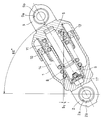
- FIG. 1 is a longitudinal sectional view showing an embodiment of a hydraulic auto tensioner according to the present invention.
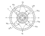
- Sectional drawing which expands and shows a part of FIG. Sectional view along line III-III in Fig. 2
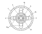
- Cross-sectional view showing another embodiment of the hydraulic auto tensioner according to the present invention 1 is a longitudinal sectional view showing an example of use of the hydraulic auto tensioner shown in FIG. 1 in an inclined state.
- the cylinder 1 has a bottom, and a connecting piece 2 connected to the engine block is provided on the bottom of the cylinder 1.
- the connecting piece 2 is provided with a shaft insertion hole 2a penetrating from one side surface to the other side surface, and a cylindrical fulcrum shaft 2b and a sliding bearing 2c for rotatably supporting the fulcrum shaft 2b in the shaft insertion hole 2a.
- the fulcrum shaft 2b is fixed by tightening a bolt that is inserted into the fulcrum shaft 2b and threadedly engaged with the engine block, and the cylinder 1 is swingably mounted around the fulcrum shaft 2b.
- a sleeve fitting hole 3 is provided on the upper surface of the bottom of the cylinder 1, and a lower end portion of a steel sleeve 4 is press-fitted into the sleeve fitting hole 3.
- the lower portion of the rod 5 is slidably inserted into the sleeve 4, and the pressure chamber 6 is provided in the sleeve 4 by the insertion of the rod 5.
- a spring seat 7 is fixed to an upper end portion of the rod 5 located outside the cylinder 1, and a return spring 8 incorporated between the spring seat 7 and the bottom surface of the cylinder 1 extends relative to the cylinder 1 and the rod 5. It is energizing in the direction to do.
- the connecting piece 9 is formed with a sleeve insertion hole 9a penetrating from one side surface to the other side surface, and a sleeve 9b and a slide bearing 9c for rotatably supporting the sleeve 9b are incorporated in the sleeve insertion hole 9a.
- the connecting piece 9 is rotatably connected to the pulley arm 33 by a bolt inserted into the sleeve 9b.
- the spring seat 7 is formed of a molded product, and a cylindrical dust cover 10 covering the outer periphery of the upper portion of the cylinder 1 and a cylindrical spring cover 11 covering the upper portion of the return spring 8 are simultaneously molded to form the spring seat 7. It is integrated.
- the spring seat 7 may be an aluminum die-cast molded product, or may be a molded product of a resin such as a thermosetting resin.
- the entire outer periphery of the spring cover 11 is covered with a cylindrical body 12 that is insert-molded when the spring seat 7 is molded.
- the cylinder 12 is made of a press-formed product of a steel plate.
- An oil seal 13 as a seal member is incorporated in the upper opening of the cylinder 1, and the inner periphery of the oil seal 13 is in elastic contact with the outer peripheral surface of the cylinder 12 to close the upper opening of the cylinder 1. This prevents the hydraulic oil filled in the inside from leaking to the outside, and prevents dust from entering the inside.
- a sealed reservoir chamber 14 is formed between the cylinder 1 and the sleeve 4.
- the reservoir chamber 14 and the pressure chamber 6 are an oil reservoir comprising an oil passage 15 formed between the fitting surfaces of the sleeve fitting hole 3 and the sleeve 4 and a circular recess formed in the center of the bottom surface of the sleeve fitting hole 3. 16 to communicate with each other.
- the oil passage 15 includes an axial groove 15 a and a radial groove 15 b that extends radially inward from the lower end of the axial groove 15 a and communicates with the oil reservoir 16.
- the upper opening 15c of the axial groove 15a has a long hole shape facing outward in the radial direction.
- the four oil passages 15 are arranged in a plane cross shape, and the upper openings 15c of the respective oil passages 15 are arranged on a reference line xx as shown in FIG. On the other hand, the position is shifted by 45 ° in the circumferential direction.
- the reference line xx passes through the center of the upper opening of the sleeve fitting hole 3 perpendicular to the axis of the sleeve 4 and the auto tensioner is swingable about the fulcrum shaft 2b shown in FIG.
- a radial straight line extending in the swing direction (a straight line in the tilt direction when the auto tensioner is tilted about the fulcrum shaft 2b).
- a check valve 17 is incorporated in the lower end portion of the sleeve 4.
- the check valve 17 closes and disconnects the communication between the pressure chamber 6 and the oil passage 15, and the hydraulic oil in the pressure chamber 6 passes through the oil passage 15. It is prevented from flowing through to the reservoir chamber 14.
- the rod 5 is formed with a ring groove 18 at a lower end portion located in the sleeve 4, and a retaining ring 19 fitted in the ring groove 18 is brought into contact with a step portion 20 formed at the upper inner periphery of the sleeve 4. The rod 5 is prevented from being pulled out.
- the amount of hydraulic oil filled in the cylinder 1 is set to be less than 70 to 85% of the internal volume in the most contracted state of the auto tensioner in which the cylinder 1 and the rod 5 are most contracted.
- This 70 to 85% of the amount of hydraulic oil enclosed corresponds approximately to 40 to 60% of the internal volume of the auto tensioner in which the cylinder 1 and the rod 5 are most extended.
- the volume of the oil sump 16 provided on the bottom surface of the sleeve fitting hole 3 is 10 to 20% of the maximum amount of hydraulic oil sealed, and the cylinder 1 and the rod 5 are rapidly expanded to increase the volume of the pressure chamber 6.
- the hydraulic oil in the oil reservoir 16 is sent to the pressure chamber 6 so that the supply of the hydraulic oil to the pressure chamber 6 is not short.
- the hydraulic auto tensioner shown in the embodiment has the above-described configuration.
- the connecting piece 2 provided at the closed end of the cylinder 1 is connected to the engine block.
- the connecting piece 9 of the spring seat 7 is connected to the pulley arm 33, and an adjustment force is applied to the pulley arm 33.
- the hydraulic oil in the pressure chamber 6 flows into the minute gap 21 formed between the inner diameter surface of the sleeve 4 and the outer diameter surface of the rod 5 and flows into the reservoir chamber 14.
- a hydraulic damper force is generated in the pressure chamber 6 due to the viscous resistance, and the pushing force applied to the hydraulic auto tensioner is buffered by the hydraulic damper force, and the cylinder 1 and the rod 5 have a pushing force and a return spring. Relatively moves slowly in the direction of contraction to a position where the elastic force of 8 is balanced.
- the oil level of the hydraulic oil is The oil passage 15 is disposed above the upper opening 15c.
- ⁇ 2 indicates the distance between the oil level of the hydraulic oil and the upper opening 15 c of the oil passage 15.
- the number of oil passages 15 is two, the two oil passages 15 are arranged at opposing positions, and the upper openings of the respective oil passages 15 are 90 ° out of phase with respect to the reference line xx in the circumferential direction. It may be arranged at the position. In this case, the inclination angle of the hydraulic auto tensioner can be further increased as compared with the case shown in FIG. 1, and the restrictions at the time of attachment can be extremely reduced.
Landscapes
- Engineering & Computer Science (AREA)
- General Engineering & Computer Science (AREA)
- Mechanical Engineering (AREA)
- Devices For Conveying Motion By Means Of Endless Flexible Members (AREA)
Abstract
底部下面に取付けられた連結片(2)がエンジンブロックに揺動自在に連結され、内部に作動油が充填されたシリンダ(1)の底部上面にスリーブ嵌合孔(3)を形成し、そのスリーブ嵌合孔(3)に下端部が挿入されたスリーブ(4)にロッド(5)を挿入する。スリーブ(4)内に設けられた圧力室(6)とスリーブ(4)の外側に設けられたリザーバ室(14)をスリーブ嵌合孔(3)とスリーブ(4)の嵌合面間に形成された油通路(15)で連通する。油通路(15)の上側開口(15c)をスリーブ嵌合孔(3)の上側開口の中心を通ってテンショナの揺動可能な方向に延びる基準線(x-x)から周方向に位相をずらして、油圧式オートテンショナの取付け傾斜角度の増大化を図る。
Description
この発明は、オルタネータやウォータポンプ、エアコンのコンプレッサ等の自動車補機を駆動するベルトの張力調整用に用いられる油圧式オートテンショナに関するものである。
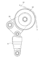
エンジンのクランクシャフトの回転を各種の自動車補機に伝えるベルト伝動装置においては、図7に示すように、ベルト31の弛み側にテンションプーリ32を支持する揺動可能なプーリアーム33を設け、そのプーリアーム33に油圧式オートテンショナAの調整力を付与して、上記テンションプーリ32がベルト31を押圧する方向にプーリアーム33を付勢し、ベルト31の張力を一定に保持するようにしている。
上記のようなベルト伝動装置に使用される油圧式オートテンショナAとして、特許文献1に記載されたものが従来から知られている。図8および図9はその特許文献1に記載された油圧式オートテンショナを示し、作動油が充填された底付きシリンダ1の底部上面にスリーブ嵌合孔3を設け、そのスリーブ嵌合孔3内に下端部が挿入されたスリーブ4内にロッド5の下部を摺動自在に挿入してスリーブ4内に圧力室6を形成し、上記ロッド5の上部に設けられたばね座7とシリンダ1の底部上面間にリターンスプリング8を組込んでロッド5とシリンダ1を伸張する方向に付勢している。
また、ばね座7の下部にリターンスプリング8の上部を覆う筒状のスプリングカバー11を設け、上記シリンダ1の上部開口に組込まれたシール部材13の内周をスプリングカバー11の外周に弾性接触させてシリンダ1とスリーブ4間に密閉されたリザーバ室14を形成し、そのリザーバ室14と圧力室6をスリーブ嵌合孔3とスリーブ4の嵌合面間に形成され油通路15で連通し、上記スリーブ4の下端開口部にチェックバルブ17を組込んでいる。
上記の構成からなる油圧式オートテンショナは、シリンダ1の底部下面に設けられた連結片2をエンジンブロックに回動自在に連結し、ばね座7の上面に設けられた連結片9を図7に示すプーリアーム33に連結して、ベルト31からテンションプーリ32およびプーリアーム33を介してシリンダ1とロッド5を収縮させる方向の押込み力が負荷された際に、チェックバルブ17を閉じ、圧力室6内に封入された作動油をスリーブ4の内径面とロッド5の外径面間に形成された微小すきま21に流動させ、その流動時の作動油の粘性抵抗により圧力室6内に油圧ダンパ力を発生させて上記押込み力を緩衝するようにしている。
ここで、シリンダ1内に封入された作動油の封入量が多くなり過ぎると、オートテンショナが最も収縮する状態において、雰囲気温度の上昇による内部圧力の上昇により作動油漏れを生じるおそれがある。
そこで、上記従来の油圧式オートテンショナにおいては、作動油の封入量を、シリンダ1とロッド5が相対的に最も収縮したオートテンショナの最収縮状態での内部体積の50%未満としている。この50%未満の作動油封入量は、シリンダ1とロッド5が最も伸長したオートテンショナの最伸長状態での内部体積の32%にほぼ相当する。
ここで、上記のような気液二相構造の油圧式オートテンショナにおいては、その取付け時の傾斜角度が大きくなって作動油の油面が油通路15の上側開口15cから下位に配置されるような組み付けであると、シリンダ1とロッド5の伸長時にリザーバ室14内の空気が圧力室6内に吸入され、収縮時にその空気を圧縮するため、油圧ダンパ効果を発揮させることができなくなる。
したがって、油圧式オートテンショナにおいては、傾斜状での組付けによる使用に際しては、作動油の油面が油通路15の上側開口15cから下位に配置されることのない組み付けとする必要がある。
ところで、上記従来の油圧式オートテンショナにおいては、圧力室6とリザーバ室14を連通する油通路15が4本とされて十字状の配置とされ、対向配置された2本の油通路15の一組が、スリーブ4の軸心と直交してスリーブ嵌合孔3の上側開口の中心を通り、オートテンショナの揺動可能な方向に延びる径方向の直線x-x(基準線x-x)を含む仮想垂直面上に配置されて、それぞれの油通路15の上側開口15cが基準線x-x上に配置されているため、オートテンショナの取付け傾斜角度を大きくとることができず、作動油の封入量との関係で垂直線からの傾斜角度αが45°を超えると、作動油の油面が油通路15の上側開口15cから下がり、取付け時の制約を受けやすいという問題があった。
なお、図8は油圧式オートテンショナの傾斜角度αが、45°未満の状態を示し、作動油の油面は油通路15の上側開口15cからδ1だけ上位に位置している。
この発明の課題は、取付け傾斜角度を大きくとることができるようにした油圧式オートテンショナを提供することである。
上記の課題を解決するために、この発明においては、作動油が充填された底付きシリンダの底部上面にスリーブ嵌合孔を設け、そのスリーブ嵌合孔内に下端部が挿入されたスリーブ内にロッドの下端部を摺動自在に挿入して、そのスリーブ内に圧力室を形成し、前記ロッドの上部に設けられたばね座とシリンダの内底面間に、シリンダとロッドを伸張する方向に付勢するリターンスプリングを組込み、前記ばね座にリターンスプリングの上部を覆う筒状のスプリングカバーを設け、前記シリンダの上側開口部内に組込まれたシール部材の内周をスプリングカバーの外周に弾性接触させて、前記シリンダとスリーブ間に形成されたリザーバ室の上部開口を密閉し、前記スリーブと前記スリーブ嵌合孔の嵌合面間に前記リザーバ室と前記圧力室を連通する油通路を設け、前記スリーブの下端部内に、圧力室の圧力がリザーバ室の圧力より高くなると閉じて圧力室と油通路の連通を遮断するチェックバルブを設け、前記シリンダの底部下面に設けられた連結片をエンジンブロックに回動可能に連結し、その連結部を中心にして揺動可能とされ、かつ、傾斜状に組み付けが可能とされた油圧式オートテンショナにおいて、前記スリーブの軸心と直交してスリーブ嵌合孔の上側開口の中心を通り、前記連結部を中心に揺動可能なテンショナの揺動方向に延びる径方向の直線を基準線として、その基準線から周方向に位相がずれた位置に前記油通路の上端開口を配置した構成を採用したのである。
ここで、油通路は、平面十字状配置の4本の油通路からなるものであってもよく、あるいは、対向配置された2本の油通路からなるものであってもよい。油通路を4本とする場合は、それぞれの油通路の上端開口が前記基準線に対して周方向に45°位相ずれした位置に配置されるようにし、また、油通路を2本とする場合は、それぞれの油通路の上端開口が前記基準線に対して周方向に90°位相ずれした位置に配置されるようにする。
この発明においては、上記のように、スリーブの軸心と直交し、スリーブ嵌合孔の上側開口の中心を通ってテンショナの揺動可能な方向に延びる径方向の直線を基準線とし、その基準線から周方向に位相がずれた位置に油通路の上端開口を配置したことにより、上記基準線上に油通路の上端開口が配置された従来のオートテンショナに比較して、そのオートテンショナの取付け時の傾斜角度を大きくとることができ、取付け時に制約を受けることが少ないオートテンショナを提供することができる。
以下、この発明の実施の形態を図1乃至図6に基づいて説明する。図1に示すように、シリンダ1は底部を有し、その底部に下面にエンジンブロックに連結される連結片2が設けられている。
連結片2には、一側面から他側面に貫通する軸挿入孔2aが設けられ、その軸挿入孔2a内に筒状の支点軸2bとその支点軸2bを回転自在に支持する滑り軸受2cとが組み込まれ、上記支点軸2b内に挿通されてエンジンブロックにねじ係合されるボルトの締め付けにより支点軸2bが固定され、その支点軸2bを中心にしてシリンダ1が揺動自在の取付けとされる。
シリンダ1の底部上面には、スリーブ嵌合孔3が設けられ、そのスリーブ嵌合孔3内に鋼製のスリーブ4の下端部が圧入されている。スリーブ4内にはロッド5の下部が摺動自在に挿入され、そのロッド5の挿入によって、スリーブ4内に圧力室6が設けられている。
ロッド5のシリンダ1の外部に位置する上端部にはばね座7が固定され、そのばね座7とシリンダ1の底面間に組込まれたリターンスプリング8は、シリンダ1とロッド5が相対的に伸張する方向に付勢している。
ばね座7の上端には図7に示すプーリアーム33に対して連結される連結片9が設けられている。連結片9には一側面から他側面に貫通するスリーブ挿入孔9aが形成され、そのスリーブ挿入孔9a内にスリーブ9bと、そのスリーブ9bを回転自在に支持する滑り軸受9cとが組み込まれ、上記スリーブ9b内に挿通されるボルトによって連結片9がプーリアーム33に回転自在に連結される。
ばね座7は成形品からなり、その成形時にシリンダ1の上部外周を覆う筒状のダストカバー10とリターンスプリング8の上部を覆う筒状のスプリングカバー11とが同時に成形されて、ばね座7に一体化されている。
ここで、ばね座7は、アルミのダイキャスト成形品であってもよく、あるいは、熱硬化性樹脂等の樹脂の成形品であってもよい。
スプリングカバー11は、ばね座7の成形時にインサート成形される筒体12によって外周の全体が覆われている。筒体12は、鋼板のプレス成形品からなる。
シリンダ1の上側開口部内にはシール部材としてのオイルシール13が組込まれ、そのオイルシール13の内周が筒体12の外周面に弾性接触して、シリンダ1の上側開口を閉塞し、シリンダ1の内部に充填された作動油の外部への漏洩を防止し、かつ、ダストの内部への侵入を防止している。
上記オイルシール13の組み込みにより、シリンダ1とスリーブ4との間に密閉されたリザーバ室14が形成される。リザーバ室14と圧力室6は、スリーブ嵌合孔3とスリーブ4の嵌合面間に形成された油通路15およびスリーブ嵌合孔3の底面中央部に形成された円径凹部からなる油溜り16を介して連通している。
図2乃至図4に示すように、油通路15は、軸方向溝15aと、その軸方向溝15aの下端から半径方向内方に延びて油溜り16に連通する径方向溝15bとからなり、上記軸方向溝15aの上側開口15cは半径方向外方に向く長孔状とされている。
油通路15は、4本とされ、その4本の油通路15は平面十字状の配置とされ、それぞれの油通路15の上側開口15cは、図3に示すように、基準線x-xに対して周方向に45°位置がずれている。
ここで、基準線x-xとは、スリーブ4の軸心と直交してスリーブ嵌合孔3の上側開口の中心を通り、図1に示す支点軸2bを中心として揺動可能なオートテンショナの揺動方向に延びる径方向の直線(支点軸2bを中心としてオートテンショナを傾けた際の傾き方向の直線)をいう。
図2に示すように、スリーブ4の下端部内にはチェックバルブ17が組み込まれている。チェックバルブ17は、圧力室6内の圧力がリザーバ室14内の圧力より高くなると閉鎖して、圧力室6と油通路15の連通を遮断し、圧力室6内の作動油が油通路15を通ってリザーバ室14に流れるのを防止するようになっている。
ロッド5には、スリーブ4内に位置する下端部にリング溝18が形成され、そのリング溝18に嵌合した止め輪19はスリーブ4の内周上部に形成された段部20に対する当接によってロッド5を抜止めするようになっている。
ここで、シリンダ1内に充填された作動油の封入量は、シリンダ1とロッド5が最も収縮したオートテンショナの最収縮状態での内部体積の70~85%未満とされている。この70~85%の作動油の封入量は、シリンダ1とロッド5が最も伸長したオートテンショナの最伸長状態での内部体積の40~60%にほぼ相当している。
また、スリーブ嵌合孔3の底面に設けられた油溜り16の容積は、作動油の最大封入量の10~20%とされ、シリンダ1とロッド5が急激に伸長して圧力室6の容積が急激に大きくなった場合に、その油溜り16の作動油が圧力室6に送り込まれて圧力室6への作動油の供給が不足することのない大きさとされている。
実施の形態で示す油圧式オートテンショナは上記の構成からなり、図7に示す補機駆動用ベルト31の張力調整に際しては、シリンダ1の閉塞端に設けた連結片2をエンジンブロックに連結し、かつ、ばね座7の連結片9をプーリアーム33に連結して、そのプーリアーム33に調整力を付与する。
上記のようなベルト31の張力調整状態において、補機の負荷変動等によってベルト31の張力が変化し、上記ベルト31の張力が弱くなると、リターンスプリング8の押圧によりシリンダ1とロッド5が伸張する方向に相対移動してベルト31の弛みが吸収される。
ここで、シリンダ1とロッド5が伸張する方向に相対移動するとき、圧力室6内の圧力はリザーバ室14内の圧力より低くなるため、チェックバルブ17が油通路15を開放する。このため、リザーバ室14内の作動油は油通路15から圧力室6内にスムーズに流れ、シリンダ1とロッド5は伸張する方向にスムーズに相対移動してベルト31の弛みを直ちに吸収する。
一方、ベルト31の張力が強くなると、ベルト31から油圧式オートテンショナのシリンダ1とロッド5を収縮させる方向の押込み力が負荷される。このとき、圧力室6内の圧力はリザーバ室14内の圧力より高くなるため、チェックバルブ17は閉鎖して、圧力室6と油通路15の連通を遮断する。
また、圧力室6内の作動油はスリーブ4の内径面とロッド5の外径面間に形成された微小すきま21に流れてリザーバ室14内に流入し、上記微小すきま21に流れる作動油の粘性抵抗によって圧力室6内に油圧ダンパ力が発生し、その油圧ダンパ力によって、油圧式オートテンショナに負荷される上記押込み力が緩衝されると共に、シリンダ1とロッド5は、押込み力とリターンスプリング8の弾性力とが釣り合う位置まで収縮する方向にゆっくりと相対移動する。
実施の形態で示すように、スリーブ4の軸心と直交し、スリーブ嵌合孔3の上側開口の中心を通ってテンショナの揺動可能な方向に延びる基準線x-xから周方向に45°位相がずれた位置に油通路15の上側開口15cを位置させるとともに、シリンダ1内に充填された作動油の封入量を、シリンダ1とロッド5が最も収縮したオートテンショナの最収縮状態での内部体積の70~85%未満とすることにより、図6に示すように、支点軸2bを中心にして油圧式オートテンショナを垂直線から60°傾斜させた取付け状態においても、作動油の油面は油通路15の上側開口15cから上位に配置されることになる。δ2は作動油の油面と油通路15の上側開口15c間の間隔を示している。
このため、図6に示す傾斜状の取付け状態における使用において、シリンダ1とロッド5の伸長時に、リザーバ室14内の空気が油通路15から圧力室6内に吸い込まれるようなことはなく、図8に示す従来の油圧式オートテンショナに比較して、オートテンショナの取付け傾斜角度を大きくとることができ、取付け時に制約を受けることが少ないオートテンショナを得ることができる。
図1乃至図4に示す実施の形態においては、スリーブ4とスリーブ嵌合孔3の嵌合面間に4本の油通路15を形成したが、油通路15の数は4本に限定されるものではない。
図5では、油通路15を2本とし、その2本の油通路15を対向位置に配置し、それぞれの油通路15の上側開口を基準線x-xに対して周方向に90°位相ずれした位置に配置するようにしてもよい。この場合、油圧式オートテンショナの傾斜角度を図1に示す場合よりさらに大きくすることができ、取付け時の制約をきわめて少なくすることができる。
1 シリンダ
2 連結片
4 スリーブ
5 ロッド
6 圧力室
7 ばね座
8 リターンスプリング
11 スプリングカバー
13 オイルシール(シール部材)
14 リザーバ室
15 油通路
15c 上側開口
17 チェックバルブ
2 連結片
4 スリーブ
5 ロッド
6 圧力室
7 ばね座
8 リターンスプリング
11 スプリングカバー
13 オイルシール(シール部材)
14 リザーバ室
15 油通路
15c 上側開口
17 チェックバルブ
Claims (3)
- 作動油が充填された底付きシリンダの底部上面にスリーブ嵌合孔を設け、そのスリーブ嵌合孔内に下端部が挿入されたスリーブ内にロッドの下端部を摺動自在に挿入して、そのスリーブ内に圧力室を形成し、前記ロッドの上部に設けられたばね座とシリンダの内底面間に、シリンダとロッドを伸張する方向に付勢するリターンスプリングを組込み、前記ばね座にリターンスプリングの上部を覆う筒状のスプリングカバーを設け、前記シリンダの上側開口部内に組込まれたシール部材の内周をスプリングカバーの外周に弾性接触させて、前記シリンダとスリーブ間に形成されたリザーバ室の上部開口を密閉し、前記スリーブと前記スリーブ嵌合孔の嵌合面間に前記リザーバ室と前記圧力室を連通する油通路を設け、前記スリーブの下端部内に、圧力室の圧力がリザーバ室の圧力より高くなると閉じて圧力室と油通路の連通を遮断するチェックバルブを設け、前記シリンダの底部下面に設けられた連結片をエンジンブロックに回動可能に連結し、その連結部を中心にして揺動可能とされ、かつ、傾斜状に組み付けが可能とされた油圧式オートテンショナにおいて、
前記スリーブの軸心と直交してスリーブ嵌合孔の上側開口の中心を通り、前記連結部を中心に揺動可能なテンショナの揺動方向に延びる径方向の直線を基準線として、その基準線から周方向に位相がずれた位置に前記油通路の上端開口を配置したことを特徴とする油圧式オートテンショナ。 - 前記油通路が、平面十字状配置の4本の油通路からなり、それぞれの油通路の上端開口が前記基準線に対して周方向に45°位相ずれした位置に設けられた請求項1に記載の油圧式オートテンショナ。
- 前記油通路が、対向配置の2本の油通路からなり、それぞれの油通路の上端開口が前記基準線に対して周方向に90°位相ずれした位置に設けられた請求項1に記載の油圧式オートテンショナ。
Applications Claiming Priority (2)
| Application Number | Priority Date | Filing Date | Title |
|---|---|---|---|
| JP2011-038321 | 2011-02-24 | ||
| JP2011038321A JP5658056B2 (ja) | 2011-02-24 | 2011-02-24 | 油圧式オートテンショナ |
Publications (1)
| Publication Number | Publication Date |
|---|---|
| WO2012115085A1 true WO2012115085A1 (ja) | 2012-08-30 |
Family
ID=46720862
Family Applications (1)
| Application Number | Title | Priority Date | Filing Date |
|---|---|---|---|
| PCT/JP2012/054072 Ceased WO2012115085A1 (ja) | 2011-02-24 | 2012-02-21 | 油圧式オートテンショナ |
Country Status (2)
| Country | Link |
|---|---|
| JP (1) | JP5658056B2 (ja) |
| WO (1) | WO2012115085A1 (ja) |
Citations (5)
| Publication number | Priority date | Publication date | Assignee | Title |
|---|---|---|---|---|
| JPH076552U (ja) * | 1993-06-29 | 1995-01-31 | 株式会社椿本チエイン | 歯付きベルト用オイル式テンショナ |
| JPH0953693A (ja) * | 1995-08-11 | 1997-02-25 | Otix:Kk | 油圧式オートテンショナ |
| JP2001221306A (ja) * | 2000-02-07 | 2001-08-17 | Otics Corp | 油圧式オートテンショナ |
| WO2007097261A1 (ja) * | 2006-02-20 | 2007-08-30 | Ntn Corporation | 油圧式オートテンショナ |
| JP2010180898A (ja) * | 2009-02-03 | 2010-08-19 | Ntn Corp | オートテンショナ |
Family Cites Families (1)
| Publication number | Priority date | Publication date | Assignee | Title |
|---|---|---|---|---|
| DE29508244U1 (de) * | 1995-05-18 | 1995-08-24 | INA Wälzlager Schaeffler KG, 91074 Herzogenaurach | Hydraulische Spannvorrichtung für einen Zugmitteltrieb |
-
2011
- 2011-02-24 JP JP2011038321A patent/JP5658056B2/ja active Active
-
2012
- 2012-02-21 WO PCT/JP2012/054072 patent/WO2012115085A1/ja not_active Ceased
Patent Citations (5)
| Publication number | Priority date | Publication date | Assignee | Title |
|---|---|---|---|---|
| JPH076552U (ja) * | 1993-06-29 | 1995-01-31 | 株式会社椿本チエイン | 歯付きベルト用オイル式テンショナ |
| JPH0953693A (ja) * | 1995-08-11 | 1997-02-25 | Otix:Kk | 油圧式オートテンショナ |
| JP2001221306A (ja) * | 2000-02-07 | 2001-08-17 | Otics Corp | 油圧式オートテンショナ |
| WO2007097261A1 (ja) * | 2006-02-20 | 2007-08-30 | Ntn Corporation | 油圧式オートテンショナ |
| JP2010180898A (ja) * | 2009-02-03 | 2010-08-19 | Ntn Corp | オートテンショナ |
Also Published As
| Publication number | Publication date |
|---|---|
| JP5658056B2 (ja) | 2015-01-21 |
| JP2012172823A (ja) | 2012-09-10 |
Similar Documents
| Publication | Publication Date | Title |
|---|---|---|
| JP5567300B2 (ja) | 油圧式オートテンショナ | |
| JP2009222081A (ja) | 油圧式オートテンショナ | |
| JP5086171B2 (ja) | 油圧式オートテンショナ | |
| US20130260931A1 (en) | Hydraulic auto-tensioner | |
| JP5112937B2 (ja) | 油圧式オートテンショナ | |
| JP5840864B2 (ja) | 補機用油圧式オートテンショナ | |
| JP5658056B2 (ja) | 油圧式オートテンショナ | |
| WO2007097261A1 (ja) | 油圧式オートテンショナ | |
| JP6013087B2 (ja) | 油圧式オートテンショナ | |
| EP3557095B1 (en) | Support structure for tensioner device | |
| JP6030487B2 (ja) | 油圧式オートテンショナ | |
| JP5820626B2 (ja) | 油圧式オートテンショナ | |
| JP6069556B2 (ja) | 油圧式オートテンショナ | |
| JP2008267456A (ja) | 油圧式オートテンショナ | |
| JP2006312969A (ja) | 油圧式オートテンショナ | |
| JP2008248925A (ja) | 油圧式オートテンショナ | |
| JP4698457B2 (ja) | 油圧式オートテンショナ | |
| JP2008202776A (ja) | 油圧式オートテンショナ | |
| JP2007071310A (ja) | 油圧式オートテンショナ | |
| JP2008032124A (ja) | 油圧式オートテンショナ | |
| JP2007315562A (ja) | 油圧式オートテンショナ | |
| JP2007010130A (ja) | 油圧式オートテンショナおよびベルトの張力調整装置 | |
| JP2008032126A (ja) | 油圧式オートテンショナ | |
| JP2008256120A (ja) | 油圧式オートテンショナ | |
| JP2007010128A (ja) | 油圧式オートテンショナおよびベルトの張力調整装置 |
Legal Events
| Date | Code | Title | Description |
|---|---|---|---|
| 121 | Ep: the epo has been informed by wipo that ep was designated in this application |
Ref document number: 12749393 Country of ref document: EP Kind code of ref document: A1 |
|
| NENP | Non-entry into the national phase |
Ref country code: DE |
|
| 122 | Ep: pct application non-entry in european phase |
Ref document number: 12749393 Country of ref document: EP Kind code of ref document: A1 |